structural and stress conditions of graphite cast irons ... · structural and stress conditions of...
TRANSCRIPT

American International Journal of Contemporary Research Vol. 3 No. 3; March 2013
49
Structural and Stress Conditions of Graphite Cast Irons after Intense Heating and
Controlled Cooling
Jan Tvarozek
Faculty of Special Technology
Alexander Dubček University of Trenčín
Pri parku 19, 911 06 Trenčín
Slovakia
Maria Lickova
Faculty of Special Technology
Alexander Dubček University of Trenčín
Pri parku 19, 911 06 Trenčín
Slovakia
Abstract
The paper addresses the impact of heating rate on treatment of selected graphite cast irons and their properties
after isothermal austempering and the applied type of heat treatment Moreover, the paper aims to correlate the type of heat treatment and the structural and stress conditions in lamellar graphite cast iron (LGCI) and
spheroidal graphite cast iron (SGCI). LGCI and SGCI heat treatment was designed to receive a hard, abrasive
and tough surface layer after surface induction marquenching while maintaining the original microstructure of the core of the material. To achieve this goal, we applied induction marquenching and evaluated the experimental
material in line with the following criteria: to determine hardness and toughness (KCO), microscopic stress
values and assess the experimental material in terms of metallographic microfractographic analysis.
Key words: structural stress, intense heating, controlled cooling, lamellar graphite cast iron, spheroidal graphite cast iron.
Introduction
There are many materials used for casting, but graphitic casts are one of the most common. Their wide range of
properties is given by the structural state of the metal matrix, shape, size and distribution of graphite. Generally,
heat treatment processes are determined by the graphite morphology. While there are no restrictions to annealing processes applied to cast iron, treatment processes with higher heating and cooling rates and significant thermal
and structural tensions, can be applied only to some types of cast iron and casts of simple shapes. Excessive
deformation and cracking have to be taken into consideration especially in technological processes during which
martensite or a blend containing martensite are formed. Notch effect caused by unfavourable morphology of graphite particles may hinder or prevent completely the use of such treatment processes such as refining, surface
hardening, etc..
Under certain circumstances, hard but brittle structures with high internal stresses can be replaced with structures
of slightly lower value of hardness, but much higher value of toughness and lower level of internal stresses.
Isothermal heat treatment applied to spheroidal graphite cast iron (Austempered Ductile Iron) is a commonly used for volumetric heat treatment of cast iron. Kinetics of the metallurgical process is characterized by less aggressive
thermal and structural changes.
Processes associated with high (for instance induction) heating followed by controlled cooling have not been used
if tough bainitic coating is the final purpose. The paper addresses the issue in terms of internal stresses,
microstructure and selected mechanical properties.

© Centre for Promoting Ideas, USA www.aijcrnet.com
50
Methods and Goals
Different types of graphite cast iron were chosen for the experimental purposes, such as lamellar graphite cast iron (LGCI) and spheroidal graphite cast iron (SGCI). Although the more demanding LGCI heat treatment has not
been commonly used, the material has undergone isothermal refinement. In comparison to other graphitic cast
iron with identical matrix and respective heat treatment, lamellar graphite shape makes mechanical properties of the lowest value. In contrast, isothermally tempered spheroidal cast iron [1], [4] features the best mechanical
properties. Experiments with cast iron with transition forms of graphite were not carried out. However, we can
assume the properties be in the range defined specifically by these "marginal" types of cast irons.
Even though SGCI isothermal refinement is of more significance in practical terms, isothermal LGCI refinement
can be advantageous for e.g. surface hardening to increase wear resistance. Blends being formed during standard
surface hardening are characterized by high values of internal stress which may cause fissures. Austempering substantially eliminates these disadvantages even in LGCI [5], [6].
Following the aforementioned, the goals of the paper are to:
- select specific types of graphitic cast iron for experimental work,
- characterize mechanical properties of selected types of cast iron following their standard marquenching and
austempering, - propose and apply an intensive method of heating specimens to austenitizing temperature,
- with respect to the heating rate, compare specimens ́ mechanical properties, values of internal stress,
structure morphology and fracture areas following their final heat treatment, - based upon the results of the experiments, propose ways and possibilities of applications using intense
heating.
Proposal of the Experiment
LGCI and SGCI heating treatment with induction heating is designed to obtain a hard, abrasion-resistant and tough coating while preserving the original microstructure of the core material.
For this purpose, the pearlitic LGCI and SGCI material was selected as the austenitizing temperature for a pearlite structure is lower than that for the structure containing a certain amount of ferrite or a completely ferritic
structure. Induction heating times were short and the austenitizing temperature chosen was by 150 °C higher than
in slow heating, such as for instance in a furnace.
After intensive induction heating of the material surface to the austenitizing temperature, the following surface
layers were formed depending on the method of cooling:
- martensitic surface layer - when cooled in water,
- bainite surface layer - when cooled in a salt bath.
Table 1: Chemical composition of experimental material (weight %), lamellar graphite cast iron (LGCI)
Chemical element C Si Mn P S Cr Cu Ni V
Content of the
element
(weight%)
3,57 2,72 0,97 0,05 0,022 0,08 0,93 0,74 0,042
Table 2: Chemical composition of the fundamental material (weight %), spheroidal graphite cast iron
(SGCI).
Chemical
element C Si Mn P S Cr Cu Ni V
Mg
Content of
the element
(weight%)
3,6 2,83 0,97 0,04 0,021 0,08 0,93 0,74 0,042
0,041

American International Journal of Contemporary Research Vol. 3 No. 3; March 2013
51
Microscopic stresses in thermally untreated LGCI
By measuring intensity of the diffraction lines of cementite, we find that LGCI specimens contain less amount of
cementite than SGCI specimens. There is small coherent diffraction area in cast iron. By measuring the width of the reflection by Sherry 220 alpha iron / ferrite, we find that the specimens have fairly high values of microstress
/mean value is 200 MPa/. LGCI specimens contain ferrite crystals where petty plastic deformations may occur. Moreover, plastic
deformability is induced by high microstresses during which adjacent ferrite crystals act on each other.
The values of internal stresses in S1, S2, S3 specimens are listed in Table 3. The assessment of stress in S1
specimen was made using the diffraction pattern No. 1. Specimens S2 and S3 were also evaluated.
Table 3: Values of internal stress in S1, S2, S3 specimens
Specimen
designation
Size of the coherent diffraction area
D(μm)
Internal stress value σ (MPa)
S1 0,12 189
S2 0,13 182
S3 0,14 220
Microscopic stresses in thermally treated LGCI
The values of internal stress in T1, T2, T3 specimens are listed in Table 4. The assessment of stress in T1 specimen was made using the diffraction pattern No. 2. Specimens T2, T3 were also evaluated.
Table 4: Values of internal stress in T1, T2, T3 specimens
Specimen
designation
Size of the coherent diffraction area
D(μm)
Internal stress value σ (MPa)
T1 0,048 87
T2 0,042 84
T3 0,049 120
Diffraction pattern 1
Specimen designation: LGCI specimen No. S1 – thermally untreated
Sensing parameters: anode: Co + sec. monochromator, U = 30 kV, I = 30 mA,
step 0,05° 2, 5s/ step

© Centre for Promoting Ideas, USA www.aijcrnet.com
52
2θ 2w B sin Θ
52,4108 0,2795 0.02447 0.44159
77,1517 0,3630 0.02769 0.62355
99,6642 0,4852 0.03053 0.76416
123,9969 0,6779 0.03105 0.88293
= 0,00833 + 0,01566.sin
ε = 0,01566. 0,380124/4 = 0,00014882
Size of the coherent diffraction area: DRP = 0,12 m
Internal stress value: = E. ε = 1,27.105*0,0014882 = 189 MPa
Lamellar graphite cast iron – X-ray pattern, S1 specimen
The X-ray diffraction pattern, using Debye – Scherrer method, shows a reflecting plane (110) representing the highest peak in the position 53 on x-axis.
sinθλ
4
D
k
λ
cosθ2wB
0.40 0.50 0.60 0.70 0.80 0.90SIN THETA
0.020
0.025
0.030
0.035
B
VZORKA 13S1
SPECIMEN
N

American International Journal of Contemporary Research Vol. 3 No. 3; March 2013
53
Diffraction pattern 2 Specimen designation: LGG No. T1 - thermally untreated
Sensing parameters: anode: Co + sec. monochromator, U = 30 kV, I = 30 mA,
step 0,05° 2, 5s/ step
2θ 2w B sin θ
52,4072 0,2782 0.02435 0.44156
77,2212 0,4250 0.03240 0.62402
99,7240 0,5268 0.03313 0.76449
123,9924 0,6558 0.03004 0.88292
= 0,02067 + 0,01372.sin
ε= 0,01372. 0,15008539/4 = 0,0005148
0.40 0.50 0.60 0.70 0.80 0.90SIN THETA
0.020
0.025
0.030
0.035
B
VZORKA 21
sinθλ
4
D
k
λ
cosθ2wB
T1
SPECIMEN
© Centre for Promoting Ideas, USA www.aijcrnet.com
54
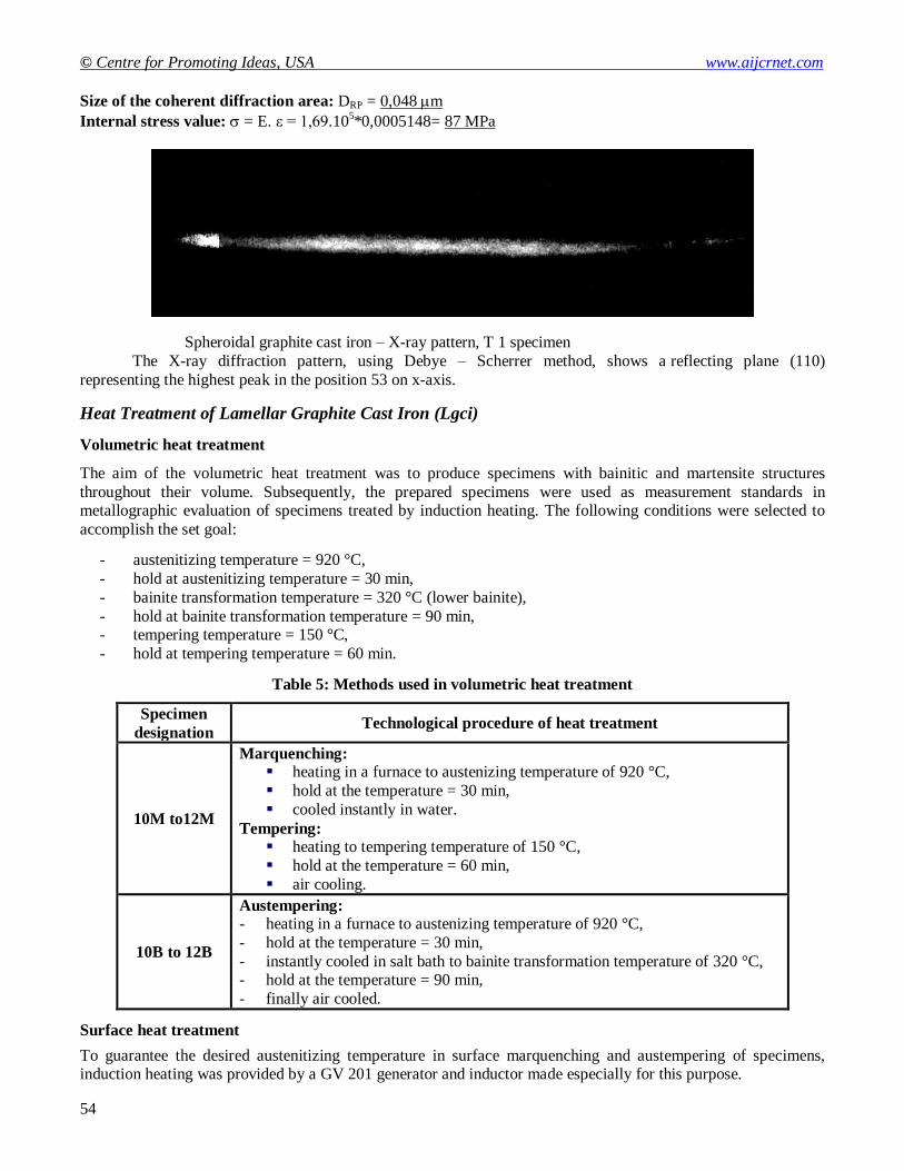
Size of the coherent diffraction area: DRP = 0,048 m
Internal stress value: = E. ε = 1,69.105*0,0005148= 87 MPa
Spheroidal graphite cast iron – X-ray pattern, T 1 specimen
The X-ray diffraction pattern, using Debye – Scherrer method, shows a reflecting plane (110)
representing the highest peak in the position 53 on x-axis.
Heat Treatment of Lamellar Graphite Cast Iron (Lgci)
Volumetric heat treatment
The aim of the volumetric heat treatment was to produce specimens with bainitic and martensite structures
throughout their volume. Subsequently, the prepared specimens were used as measurement standards in metallographic evaluation of specimens treated by induction heating. The following conditions were selected to
accomplish the set goal:
- austenitizing temperature = 920 °C,
- hold at austenitizing temperature = 30 min,
- bainite transformation temperature = 320 °C (lower bainite),
- hold at bainite transformation temperature = 90 min, - tempering temperature = 150 °C,
- hold at tempering temperature = 60 min.
Table 5: Methods used in volumetric heat treatment
Specimen
designation Technological procedure of heat treatment
10M to12M
Marquenching: heating in a furnace to austenizing temperature of 920 °C,
hold at the temperature = 30 min,
cooled instantly in water.
Tempering: heating to tempering temperature of 150 °C,
hold at the temperature = 60 min,
air cooling.
10B to 12B
Austempering: - heating in a furnace to austenizing temperature of 920 °C,
- hold at the temperature = 30 min,
- instantly cooled in salt bath to bainite transformation temperature of 320 °C, - hold at the temperature = 90 min,
- finally air cooled.
Surface heat treatment
To guarantee the desired austenitizing temperature in surface marquenching and austempering of specimens, induction heating was provided by a GV 201 generator and inductor made especially for this purpose.

American International Journal of Contemporary Research Vol. 3 No. 3; March 2013
55
In the course of heating in the inductor, the specimens were placed on a tray made of copper sheet and copper pins (Fig. 1). After the austenitizing temperature is reached, the specimen can be cooled instantly. The specimen
position on a tray is shown in Fig. 2. Reaching the austenitizing temperature in the surface layer was determined
subjectively by reading the standard colors emitted. Specimen heating time ranged from 12 to 186 seconds.
Salt bath (AS 140 salt) preheated to the desired temperature was used to reach the bainite transformation temperature. The temperature was held constant during the bainite transformation.
FLUKE 51 digital thermometer with NiCr-Ni thermocouple was used to check the temperature of the salt bath.
155
482
Ø2,8
50
2515
Fig. 1 Shape and dimensions of the tray
Fig. 2 Position of the specimen on the tray
The following parameters were selected for the surface heat treatment:
- austenitizing temperature = 920 °C,
- hold at austenitizing temperature = 0 min,
- bainite transformation temperature = 320 °C (lower bainite), - hold at bainite transformation temperature = 90 min.
Technological procedure of the induction heat treatment of specimens is listed in Table 6.

© Centre for Promoting Ideas, USA www.aijcrnet.com
56
Table 6: Applied procedures of surface heat treatment
Specimen
designation Technological procedure of heat treatment
10 to 14
Surface induction marquenching:
- fast and intense induction heating to austenitizing temperature of 920 °C,
- after reaching the temperature, instantly cooled in running water.
15 to 19
Surface induction austempering: - fast and intense induction heating to austenitizing temperature of 920 °C,
- after reaching the temperature, instantly cooled in salt bath to bainite
transformation temperature of 320 °C, - hold at austenitizing temperature = 90 min,
- finally air cooled.
Mechanical testing
Mechanical tests were performed in line with the following standards:
- STN EN ISO 6508-1 – Rockwell hardness test, - STN EN ISO 6507-1 – Vickers hardness test,
- STN EN 10 045-1 – blow bending test.
Rockwell hardness test (HRC)
Hardness HRC was measured in five points along the entire specimen (Fig. 3).
Fig. 3 Points of penetration when measuring HRC
(the distance between points of penetration was 10 mm)
The results indicate that the hardness value of volumetrically treated specimens is almost constant along their
entire length. Surface treated specimens have lower hardness value on edges (points of penetration 1 and 5) than
in the centre (point of penetration 3). The hardness value variations were caused by induction heating as edges and corners of the specimens were heated first. Extreme heat load in the vicinity of these points formed fissures
on the edges of the specimens, thus facilitating the penetration of the indentor into the material under test. Based
on the results, the Vickers hardness test was proposed and carried out.
Metallographic analysis
Metallographic analysis was performed in line with STN 42 0461 setting out procedures to describe in the qualitative and quantitative manner the elements which can most frequently be found in cast iron, such as
graphite, ferrite, pearlite, cementite and phosphide eutectic. Base material and heat treated material were analysed.
NEOPHOT 2 light microscope was employed to assess the structure visually. The results of metallographic assessment are as follows [9], [10]:
- Base material: The structure of the material is made up of laminated graphite and metal matrix consisting of lamellar pearlite (Fig. 4). Entry in line with the standard: I A 4 – P1 – P 96 – Pd 1,4. The standard notation
in wording reads as follows: The notation defines the LGCI structure with lamellar graphite of the size 120 up
to 250 μm. Graphite is distributed evenly. In addition, the structure contains lamellar pearlite with a dispersion of 1,3 up to 1,6 μm and ferrite exceeding 2 per cent of the structure. The structure also comprises
a certain amount of unspecified impurities.
1 2 3 4 5

American International Journal of Contemporary Research Vol. 3 No. 3; March 2013
57
- Material after being marquenched and tempered: The structure consists of lamellar graphite and a matrix
made up of martensite and residual austenite (Fig. 5) [2], [3].
- Material after being austempered: The structure consists of lamellar graphite and a matrix made up of
bainite and residual austenite. The content of residual austenite is higher than in the marquenched and tempered material (Fig. 6).
- Material after being surface induction marquenched: Due to short induction heating austenitizing times,
extremely fine martensite of specific morphology with no distinctive plate-shaped or needle-shaped formations (Fig. 7) in the surface layer was formed. The figure also shows fissures emerging primarily by
sharp edges of flakes if additional graphite is present in the vicinity. The fissures indicate the emergence and
presence of extreme stress after water cooling. Moving towards the core, the HV10 hardness value slightly decreases, but fissures are no longer present, and if so, just a few of them.
- Material after being surface induction austempered: The surface layer structure consists of lamellar
graphite and a matrix made up of bainite and residual austenite. There is more residual austenite than in the
water cooled material. Fissures are not formed on the surface (Fig. 8) [7], [8].
Metallographic analysis shows that martensite having been formed after induction heating has developed a
specific morphology. The special morphology was developed because the austenitizing temperature is reached in very short times in induction heating and conditions for austenite homogenization are severely limited. Bainite
obtained via induction heating is finer than bainite obtained via furnace heating.
Fig. 5 Microstructure of the material after
marquenching and tempering, etch. pikric
acid, 500x
zv.500x
Fig. 4 Microstructure of the base material,
etch. pikric acid, 500 x.

© Centre for Promoting Ideas, USA www.aijcrnet.com
58
Microfractographic assessment fracture surfaces
Microfractographic assessment of specimens’ fracture surfaces after the blow bending test showed the following:
Fracture surface of the base material (thermally untreated) is characterized by a mixed type of disruption
(Fig. 9), such as:
a) disruption of pearlite:
- transcrystalline cleavage, - transcrystalline ductile fracture,
- oddeľovaním lamiel.
b) disruption in intermediate pearlite-graphite positions.
Fig. 6 Microstructure of the material after austempering, etch.
pikric acid, 500x
Fig. 8 Microstructure of the material after induction
surface austempering, specimen surface, etch. pikric
acid, 500 x.
Fig. 7 Microstructure of the material after
surface induction marquenching,
specimen surface, etch. pikric acid, 500 x
x.

American International Journal of Contemporary Research Vol. 3 No. 3; March 2013
59
Fracture surface of the material after surface induction marquenching.
Surface layer of the specimen: The following can be seen in the fracture surface (Fig. 10):
- flakes of graphite,
- areas of disruption alongside the phase boundaries, - matrix distruptions.
Fracture surface of the material after surface induction austempering.
Surface layer of the specimen:
In general, disruptions develop in intermediate graphite-metal positions. Matrix disruptions are rarely
developed (Fig. 11).
Microfractographic assessment indicates that experimentally manufactured material comprises a large amount of lamellar graphite in its structure as confirmed by mechanical testing and metallography. Lamellar graphite acts as
a stress concentrator within the structure and causes negative effects during heat treatment. Graphite strength can
be ignored in comparison to the strength of the metal matrix, thus significantly reducing the mechanical properties of the material.
Fig. 9 Fracture area of the base material Fig.10 Fracture area of the material after
induction marquenching (surface)
Fig. 11 Fracture area of the material after
induction austempering (surface)

© Centre for Promoting Ideas, USA www.aijcrnet.com
60
Determination of microscopic stress in induction marquenched LGCI
- temperature of marquenching 920 °C
a) cooling medium – water
b) cooling medium – salt AS 140 Values of structural stress states were obtained via diffraction analysis, similarly as in specimens with no
heat treatment.
After checking by means of the AI standard, the HZG 3 goniometer shows the peak values have to be corrected
by this value, i.e. 0.04 degrees have to be added to the theta angle. Tabulated data for alpha iron: lattice parameter a = 2,8664 .10
–10 m, interplanar distance d = 1,1702.10
-10 m. At a wavelength of molybdenum radiation K – alpha I
= 0.7093 A, it is a diffraction angle theta = 17.64 degrees. The values of structural stresses obtained are shown in
Tables 7 and 8.
Table 7: Values of structural stress, cooling medium – water
Specimen designation Cooling medium D /μm/ σ[MPa]
SK1 0.03 993
SK2 Water 0.013 966
SK3 0.03 917
Table 8: Values of structural stress, cooling medium – salt AS 140
Specimen
designation
Cooling medium D /μm/ σ [MPa]
SK4 0.13 570
SK5 Salt AS 140 0.01 590
SK6 0.01 512
Heat Treatment of Spheroidal Graphite Cast Iron Specimens
Volumetric heat treatment of specimens
Specimens 2M and 2B were volumetrically heat treated to structures of martensite and bainite. They served to
identify the basic properties of conventionally heat treated specimens and to compare their structures and properties with surface treated specimens.
Heat treatment conditions:
- specimen 2M (marquenched): base material from LGCI was heated to austenitizing temperature of 920 °C,
hold at temperature for 30 minutes, then cooled in 20° C water and tempered at 150° C / 1 hour.
- specimen 2B (austempered): base material from LGCI was heated to austenitizing temperature of 920 °C, hold at temperature for 30 minutes, then cooled in salt bath AS 140 at temperature of 320 °C, hold at
temperature for 90 minutes, cooled in the open air.
Surface heat treatment of specimens
Specimens were marked in the following way:
- specimen No. 2 – heat untreated base material,
- specimen 2M – volumetrically heat treated specimen to martensite, - specimen 2B – volumetrically heat treated specimen to bainite,
- specimens No. 20, 21, 22, 23, 24 – surface heat treated to martensite,
- specimens No. 25, 26, 27, 28, 29 – surface heat treated to bainite.
To obtain a martensitic surface layer, specimens No. 20, 21, 22, 23, 24 were cooled in water (20° C). Specimens
No. 25, 26, 27, 28, 29 were used to produce bainite surface layer. The process of cooling was carried out in the
AS 140 salt bath at the temperature of 320 °C for 90 minutes and then in the open air. The salt bath temperature was measured with a Fluke 51 digital measuring device type with a thermocouple (NiCr-Ni).

American International Journal of Contemporary Research Vol. 3 No. 3; March 2013
61
Mechanical tests
Methodology used for LGCI was also employed to carry out mechanical tests. The measured hardness values of the surface layers are in line with HRC.
For purposes of comparison, average hardness values and impact toughness values for specimens 2M (volumetrically processed to martensite), 2B (volumetrically processed to bainite) and specimens No. 2 (base
material) and surface treated specimens No. 20 to 29 are shown in Table. 9
Table 9: Average hardness values and impact toughness values.
Specimen
Average
heating
time
Cooling HRC hardness
Notch
toughness
KCO [J.cm-2
]
2 - - 24 16
2M 30 min. Water 20 °C 56 4
2B 30 min. AS 140 320 °C/ 90 min. 45 40
20 to 24 13 s. Water 20 °C 62, 60, 59, 60, 61 10
25 to 29 14 s. AS 140 320 °C/ 90 min. 49, 47, 46, 47, 48 32
Metallographic assessment
Metallographic analysis of the base material microstructure (Fig. 12) was performed according to the norm STN
42 0461. Graphite is discharged in the form of regular granular VI in the structure of the base material. The size of
graphite nodules is 6 (above 30 up to 60 m). The cast iron has ferrite and pearlite structure, containing pearlite P92 (above 90 up to 94%) and ferrite Fe8 (above 6 up to 10%). Pearlite is a lamellar P1 structure and its Pd
dispersion is 1.4 (above 1.3 up to 1.6m ). The following notation corresponds with the analysis: VI 6 – P1 – P92
– Pd 1.4
Fig. 12 Microstructure of the base material, etch. pikric acid, 100 x
The standard specimen structure was analysed with a light microscope. A microstructure of the martensitic heat-
treated specimen (2M) is shown in Fig.13 and a microstructure of the austempered specimen (2B) is shown in Fig.
14
© Centre for Promoting Ideas, USA www.aijcrnet.com
62
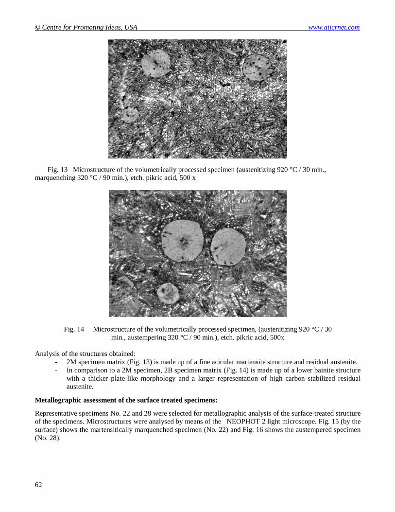
Fig. 13 Microstructure of the volumetrically processed specimen (austenitizing 920 °C / 30 min., marquenching 320 °C / 90 min.), etch. pikric acid, 500 x
Fig. 14 Microstructure of the volumetrically processed specimen, (austenitizing 920 °C / 30
min., austempering 320 °C / 90 min.), etch. pikric acid, 500x
Analysis of the structures obtained:
- 2M specimen matrix (Fig. 13) is made up of a fine acicular martensite structure and residual austenite.
- In comparison to a 2M specimen, 2B specimen matrix (Fig. 14) is made up of a lower bainite structure
with a thicker plate-like morphology and a larger representation of high carbon stabilized residual austenite.
Metallographic assessment of the surface treated specimens:
Representative specimens No. 22 and 28 were selected for metallographic analysis of the surface-treated structure of the specimens. Microstructures were analysed by means of the NEOPHOT 2 light microscope. Fig. 15 (by the
surface) shows the martensitically marquenched specimen (No. 22) and Fig. 16 shows the austempered specimen
(No. 28).

American International Journal of Contemporary Research Vol. 3 No. 3; March 2013
63
Fig. 15 Microstructure of the martensitic surface layer up to 2 mm (heating 13 s., 20 °C water cooled), etch. pikric acid, 500 x
Fig. 16 Microstructure of the isothermally heat treated surface layer up to 2 mm
(heating 14 s., austempering 320 °C / 90 min.),
etch. pikric acid, 500 x
Assessment of the surface layers of structures obtained:
Marquenched surface layer of the LGCI matrix, specimen No. 22 (Fig. 15), is made up of martensite and a low
content of residual austenite. Moving inwards the specimen, the proportion of untransformed ferrite from the
original structure increases, because it could not be sufficiently saturated with carbon due to imperfect austenitizing process at high heating rate.
Austempered specimen No. 28 (Fig. 16) is made of bainitic ferrite and stabilized high carbon austenite. Similarly,
moving inwards the specimen, the proportion of untransformed ferrite from the original structure increases due to imperfect austenitizing at high heating rate. Bainite transformation took place merely in austenitizing areas of the
lamellar pearlite and portion of ferrite. Furthermore, bainite transformation took place only in areas of lamellar
pearlite austenitizing. Next, imperfect austenitizing due to high heating rate and short hold at austenitizing temperature initiated saturation of ferrite with carbon, yet the transformation to austenite was not complete.
Microfractographic assessment of surface area fractures
After breaking, microfractographic nature of the rupture was analysed in specimens No. 2 (base material), No. 22
(martensitic surface layer) and No. 28 (bainite surface layer) with a scanning electron microscopy (SEM).

© Centre for Promoting Ideas, USA www.aijcrnet.com
64
Fracture area morphology of the base material is shown in Fig. 17. Fracture area morphology of the martensitic surface layer is shown in Fig. 18 and that of bainite surface layer is shown in Fig. 19.
Fracture surface of the base material is characterized by transcrystalline cleavage, mostly through pearlite. The entire fracture area of the martensitic surface layer is characterized by transcrystalline fracture. In the vicinity of
graphite, cleavage facets of ferrite can be observed and quasi-cleavage can be observed in the remaining structure.
When moving away from the martensitic surface layer towards the less affected base material, transcrystalline
cleavage prevails.
Fracture surface of the bainitic surface layer is characterized by a mixed nature of disruption. Ductile fracture and
dimple morphology and quasi-cleavage can be observed. Moving towards the fracture surface centre of the
specimen, cleavage facets of the cleavage disruption are on the rise.
Fig. 19 Fracture surface of the bainite surface layer
Fig. 17 Fracture surface of the base material Fig.18. Fracture surface of the
martensite surface layer

American International Journal of Contemporary Research Vol. 3 No. 3; March 2013
65
Determination of microscopic stress in induction marquenched SGCI
- marquenching temperature 920 °C - heating time to reach marquenching temperature 13s
c) cooling medium – water
d) cooling medium – salt AS 140
Values of structural stress states were obtained by means of a diffraction analysis as obtained in specimens with no heat treatment.
After checking by means of the AI standard, the HZG 3 goniometer shows that angles 15 – 20 have approximately by 0.04 degrees less. It follows that the measured values of diffraction peaks have to be corrected
by this value, 0.04 degrees have to be added to the theta angle.
Tabular data for alpha iron: lattice parameter a = 2,8664.10-10m, interplanar distance d = 1,1702.10-10 m. At a
wavelength of molybdenum radiation K – alpha I = 0.7093 A, it represents a diffraction angle theta = 17.64
degree.
Values of structural stress are provided in Tables 10 and 11.
Table 10: Values of structural stress, cooling medium – water
Specimen
designation Cooling medium
D /μm/ Stress
σ (MPa)
TK1 0.02 1262
TK2 water 0.02 1197
TK3 0.17 1140
Table 11: Values of structural stress, cooling medium – salt AS 140
Assessment of results for LGCI
An overview of mechanical and physical values measured in the experimental LGCI material is provided in
Table 12.
Table 12: An overview of mechanical and physical values measured in the experimental LGCI material.
Hardness
HV10 [HRC]
Impact toughness
KCO [J.cm-2]
Microscopic stress
[MPa]
Cooling
medium
Heat treatment
method
203-216 3 189-200 - Base material (with no
heat treatment (HT))
510-545
[49-51] 2 1055-1149 Water HT – volumetric
marquenching + tempering
290-305
[29-31] 7 560-649 Salt AS 140 HT- volumetric austempering
360-430
[37-43] 2 917-993 Water HT – surface induction
marquenching
245-255
[22-24] 5 512-570 Salt AS 140 HT – induction surface
austempering
Lower hardness values are primarily caused by high density of lamellar graphite. Metallographic analysis
revealed fissures made up of martensite in the surface layer. Fissures were formed primarily by sharp edges of
graphite flakes if additional graphite is present in the vicinity. No fissures were found in the bainitic structure.
Specimen
designation Cooling medium
D /μm/ Stress
σ (MPa)
TK4 0.013 966
TK5 salt AS 140 0.01 991
TK6 0.014 916

© Centre for Promoting Ideas, USA www.aijcrnet.com
66
Toughness value of the bainite structure specimens in blow bending test was by 67% higher when compared to the toughness of the base material. Toughness values of specimens with martensitic surface layer were of lower
values when compared to the toughness value of the base material.
Metallographic analysis shows that the martensite formed by induction heating is much finer compared to the
martensite formed by slow heating. Moreover, bainite formed by rapid heating is much finer than the bainite in
the specimen which was formed by slow heating.
Moving towards the core of the heat treated specimen, morphological features of the structure were not markedly
altered. It is caused by heating almost the entire volume of the specimens to the austenitizing temperature. The
core of the heat-treated specimens cooled in a salt bath contains the eutectic of phosphide, partially reducing the value of the specimen impact toughness.
The metallographic analysis of the microfractographic analysis of fracture areas indicates that the martensitic structure has a greater proportion of low energy brittle disruption, whereas the bainite surfaces have a much
higher proportion of high-energy ductile disruption. This finding relates to the identified mechanical properties of
the specimens.
The values of structural stress conditions obtained in LGCI specimens indicate that microstresses in materials
directly depend on the method of heat treatment. In particular, it can be observed when comparing values of
mictrostress of volumetric HT with water cooling to HT with cooling in the AS 140 salt. Values of microstress of volumetric HT with water cooling are high, while values of mictrostress for HT with cooling in the AS 140 salt
are approximately by 46% lower. Lower values of internal stress (in specimens quenched in salt) make toughness
values much higher (KCO = 7J x cm "') in comparison to water quenched specimens (KCO = 2J x cm"2).
As confirmed by the results presented, the finding also applies to the following HT process.
In rapid surface heating to martensite, the values of microstress are much higher than in the experimental material
which was induction austempered to bainite. Lower values of structural stress bring about much higher toughness
values (KCO = 5J x cm"2) than in the former HT (KCO = 2J x cm"
2).
An interesting conclusion is drawn when comparing volumetric HT with induction surface HT. In volumetric
HT, structural stress values are higher due to overheating of the material and a higher temperature gradient in the
subsequent cooling.
Assessment and evaluation of LGCI
A list of mechanical and physical measurements of the LGCI experimental material is provided in Table 13.
Table 13: List of mechanical and physical measurements of the LGCI experimental material.
Hardness
[HRC]
Impact toughness
KCO [ J.cm -2 ]
Microscopic stress
[MPa] Cooling
medium
Heat treatment
method
24-25 16 84-120 - Base material (with no
heat treatment (HT))
54-57 12 1043-1160 Water HT – volumetric
marquenching + tempering
44-46 40 876-907 Salt AS 140 HT– volumetric austempered
59-63 10 1140-1262 Water HT – surface induction
marquenched
46-49 32 916-966 Salt AS 140 HT – induction austempered
LGCI hardness values indicate lower hardness values of bainite surface layers (up to 62 HRC).
Hardness transition to the base material has more favourable conditions in bainitic surface layers than martensitic
surface layers. Therefore, bainitic surface layers have lower internal stress values. Neither disruption of the material nor fissures occurred under the selected heat treatment procedures.

American International Journal of Contemporary Research Vol. 3 No. 3; March 2013
67
Following the results, we can conclude that bainitic surface layers can be used for producing of parts with complex shapes. On the other hand, martensitic layers are not appropriate as they may initiate fractures due to
high internal stresses.
Due to different austenitizing temperature reached in the specimen depending on the distance from the surface,
the surface hardness varied, which also applies for bainitic surface layers. Concerning toughness, the most suitable are specimens isothermally treated to bainitic structure.
The visual aspect of the SGCI base material fracture, martensitic surface treated specimens and isothermally
surface treated specimens was analysed through electron microscope.
Fracture surface of the base material is characterized by transgranular cleavage, mostly to pearlite (Fig. 17).
Quasi-crystalline and quasi-cleavage fractures can be observed in the martensitic fracture surface (Fig. 18).
Transcrystalline fracture with dimple morphology and quasi-cleavage are prevalent in the fracture area of the
bainitic surface layer (Fig. 19).
Findings related to the structural stress values measured in the experimental SGCI material confirmed the
previous measurements taken in LGCI specimens. It follows that micro-stresses inside the material depend
directly on the heat treatment applied. It is the hardness and toughness that reflect the structural stresses.
Microscopic stress values of the SGCI material heated slowly to martensitic structure are lower than the values obtained by rapid heating. Similarly, the values obtained via slow heating to bainitic structure were lower than the
values obtained via induction austempering.
In LGCI specimen, more austenite was formed. Austenite formed in LGCI was more "saturated" with carbon than
SGCI austenite whose spherical graphic particles get less dissolved to the marquenching temperature in the
process of heating.
Comparing the diffractograms of specimens No. TK1 (SGCI) and No. SK2 (LGCI), we see that the spheroidal
graphite cast iron contains some coarse crystals, while SGCI specimens have no conditions to have carbon diffused.
The specimen SK4 (LGCI) contained a few rough polygons of a pearlitic matrix (approximately 30 um), probably caused by slower cooling in the salt bath when crystals had time to grow. On the other hand, in specimen No.
SK1 (LGCI) which was water marquenched, no conditions for the carbon diffusion were provided.
The same was found after comparing various cooling methods for the spheroidal graphite cast iron specimens.
Diffraction patterns show that the structural stress values are much lower in specimens cooled in AS 140 salt than
in specimens marquenched in water.
Comparing stress conditions and their influence on the mechanical properties of materials indicate that increased stress values go hand in hand with increased hardness values.
Following the results of tests and measurements, we can conclude that the mass of metal in SGCI and LGCI specimens does not have high internal stress values which would cause cracking during rapid (induction) heating
followed by controlled cooling (in molten salt).
Conclusion
Requirements for the useful properties of products made from lamellar graphite cast iron and spheroidal graphite
cast iron are constantly increasing as the material (in particular SGCI) is extensively used to replace steel castings. In addition to metallurgical processes, mechanical and technological properties of SGCI in particular have been
enhanced by heat treatment. Thus, SGCI material offers a wide range of applications in mechanical engineering
and transport industry. Remarkable results were mainly obtained in austempering.
Cooling factors play an important role for the production of high quality ADI cast iron. Salt bath represents an
optimum cooling environment for the isothermal hold at the transformation temperature.

© Centre for Promoting Ideas, USA www.aijcrnet.com
68
Price, environmentally demanding work space and adverse impact on the environment are some of the drawbacks of salt baths. Buying and maintaining salt baths in operation are costly, therefore some manufacturers are against
the production of ADI castings. Governmental regulations must be observed when working, dealing with
and storing toxic substances and technical poisons. High consumption of molten salt is another reason why manufacturers do not favour their use. The cool one kilogram of material, the weight of the salt needed is to be 10
up to 20 times higher. It follows that the procedure is costly in terms of energy required for the operation of
molten salts.
Moreover, structural stress conditions in cast iron surfaces with various shape of graphite after induction
marquenching were investigated by means of the X-ray diffraction analysis. The investigation revealed the following novel findings:
- While researching structural conditions in LGCI and SGCI cast irons, it was found that microstresses are determined by the type of heat treatment. For the experimental purposes, the following heat treatment
technologies were used:
a) volumetric heat treatment of LGCI and SGCI materials b) induction marquenching of cast iron surfaces (LGCI, SGCI)
The findings correlate the type of cooling medium with the microstress values. This finding was
confirmed in both LGCI and SGCI cast irons. The following types of cooling media were used in both types of heat treatment:
a) water
b) AS 140 salt
- Investigation of the structural stress values in LGCI and SGCI experimental materials revealed a correlation between microstress, hardness and notch toughness. Increased microstress values bring about
higher values hardness, but values of notch toughness decrease.
- Depending on the type of heat treatment, surface properties (martensite, bainite) were identified by means of mechanical and physical testing.
In addition, we have dealt with LGCI and SGCI austempering in order to enhance their useful
properties.
For engineering practice, mainly bainite structures are more appropriate. In comparison to martensite structures,
they have higher notch toughness value and do not tend to crack. One of the disadvantages of bainitic surface
layers is their costly production. A possible way to reduce the costs of production is to employ internal heat of the cast and exclude molten salt from the production process. The material volumetrically heated to the
isothermal transformation temperature would be induction surface heated to the austenizing temperature and then
cooled by a water spray while using the isothermal transformation temperature required. In order to hold at the
temperature of isothermal transformation, the inner heat of the casting would be used.
Moreover, we concentrated on various uses of the X-ray diffraction analysis, such as for instance the phase
composition of the material, presence of microscopic stress, grain size, depth profile of the element concentrations altering the composition of the relevant phase, preferential grain orientation (texture), etc.
In the process of investigating the optimization of heat treatment, X-ray diffraction analysis has the following advantages compared to mechanical methods of determining stresses:
a) The method is not destructive. Deformations can be measured in the same location of the body at various heat treatment stages.
b) Induction marquenching goes hand in hand with a steep stress gradient in the surface layers,
and the stress value in the surface layers can only be determined via X-ray diffraction analysis. c) If phase transformations develop in the course of the heat treatment (for instance the formation of austenite
and martensite), X-ray diffraction analysis is generally the only to determine stress in various stages.
These facts clearly indicate that X-ray diffraction analysis is a unique method for the investigation of structural
and stress conditions of cast irons (as well as other materials). The method is of special importance in induction
marquenched materials as the method can be employed to optimize technological process of heat treatment.

American International Journal of Contemporary Research Vol. 3 No. 3; March 2013
69
References
BECHNÝ, L.: Zlievárenská metalurgia a technológia. ALFA Bratislava. 1990
DURMIS, I.: Tepelné spracovanie ocelí a liatin. In. Odborné vzdelávanie pracovníkov v zlievárenstve v oblasti
ţelezných a neţelezných kovov. [Zborník prednášok]. 1. vyd. EDIS Ţilina, 2002, str. 85-101
FABIAN, P.: Optimalizácia technológie výroby odliatkov z bainitických liatin. [Doktorandská dizertačná práca].
Ţiliny, ŢU, Strojnícka fakulta, 2000,100 str.
HAMPL, J.: Hodnotenie metalurgickej kvality grafických liatin. Doktorandská dizertačná práca. KTI, SjF ŢU
Ţilina, 1997
KRSAY, S. I.: Ductile iron II – engineering design properties applications, Quebeck iron and titanium
corporation, 1971
MATEJKA, M.: Technologické podmienky výroby a riadené ochladzovanie presných odliatkov z grafitických liatin. Kandidátska dizertačná práca. Ţilina, 1991
ROHRBACH, Ch. Handbuch für experimentalle Apannungsanalyse, VDI-Verlag GmbH, Düsseldorf 1989
SCHOLTES, B. Eigenspannungen in mechanisch randschichtverformten Werkstoffzu ständen, DGM
Informationsgesellschaft mbH, Oberursel 1990
SKOČOVSKÝ, P.-ŠIMAN, I.: Štruktúrna analýza liatin. ALFA Bratislava, 1989
VASILKO, K. at al.: Nové materiály a technológie ich spracovania. ALFA Bratislava, 1990.
VĚCHET, S. – KOHOUT, J.-BOKŮVKA, O.: Únavové vlastnosti tvárné litiny. 1. vyd. EDIS Ţilina, 2001, 157
str.