issn : 0974 - 7486 volume 14 issue 11 materials science · spheroidal graphite cast irons highly...
TRANSCRIPT
Test of elaboration protocols for obtaining highly Co- or Ni -alloyedspheroidal cast irons from an industrial SG cast iron. Part C: Second
protocol for 25M75Fe cast irons. Subpart 1: Obtained microstruc-tures and room temperature hardness
Kamel Meridja, Patrice Berthod*, Elodie ConrathInstitut Jean Lamour (UMR 7198), Team 206 �Surface and Interface, Chemical Reactivity of Materials� Faculty
of Sciences and Technologies, University of Lorraine, B.P. 70239, 54506 Vandoeuvre-lès-Nancy, (FRANCE)
E-mail: [email protected]
Full Paper
Spheroidal graphite castiron;
Nickel;Cobalt;
Microstructure;Optical microscopy;
SEM.
KEYWORDSABSTRACT
Spheroidal Graphite cast irons highly alloyed with nickel or with cobaltwere produced by foundry from parts of an industrial SG cast iron, byfollowing a protocol which recently proved its efficiency, despite that noadditional spheroidisation and inoculation treatments of the liquid metalwas done. The same protocol was applied to obtain a control samplecontaining only iron. For the obtained 25wt.%Ni- and 25wt.%Co-containingcast irons the graphite issued from this protocol is very close to thespheroidal geometry. Obtaining highly alloyed SG cast iron following thisoriginal elaboration route was thus successful. The matrix of the obtained25wt.%Ni- and 25wt.%Co-containing cast alloys was influenced by thepresence of these new elements in so high quantities: absence of thehypoeutectic character of the control sample, respectively metallic matrixor ferrite-pearlitic matrix instead the ledeburite of the control sample.Graphitizing properties were found again for nickel and revealed for cobalt.The differences of Vickers hardness between the three cast irons wereeasily explained and hypothesis were formulated, from the response ofthe microstructures to the Nital etching, about the corrosion resistance ofthese two highly alloyed SG cast irons. 2016 Trade Science Inc. - INDIA
INTRODUCTION
Cast irons may be simple Fe-Si-C alloys con-taining only traces of other elements[1, 2] or they canbe alloyed with several elements simultaneously (e.g.Ni, Co, Mo, Ti�) whose contents may be of around
1 wt.% each[3]. They can be also alloyed specifi-
cally with Cr and Ni[4] or only Ni[5, 6] for a bettercorrosion resistance or better mechanical proper-ties[7]. Cobalt can be also present in the chemicalcomposition of cast irons, simultaneously with Ni[8,9]
or not. Some grey cast irons (with flake graphite orspheroidal graphite), highly alloyed to nickel con-tain about 20-25wt.%Ni, already exist, but often with
Materials ScienceMSAIJ, 14(11), 2016 [435-442]
An Indian Journal
Volume 14 Issue 11
Materials ScienceISSN : 0974 - 7486
id2063316 pdfMachine by Broadgun Software - a great PDF writer! - a great PDF creator! - http://www.pdfmachine.com http://www.broadgun.com
.436 Test of elaboration protocols for obtaining highly Co- or Ni -alloyed spheroidal cast irons
Full PaperMSAIJ, 14(11) 2016
An Indian JournalMaterials ScienceMaterials Science
presence of other elements than Fe, Si, C and Ni.Similar cast irons, with cobalt instead nickel in thesame contents, are rarer. In this work we were in-terested by spheroidal graphite cast irons, only con-taining Fe, Si, C and either Ni or Co, with 25wt.%in both cases. In this first part we describe how weelaborate them and the microstructures that have theobtained ingots. In a second part we will present themechanical properties of these 25wt.%Ni or25wt.%Co-containing cast irons.
EXPERIMENTAL
Elaboration of the alloys
The alloys of interest in this work were elabo-rated following the procedure which recently ledmore to spheroidal graphite than in the first elabo-rations that we did involving the re-melting of in-dustrial SG cast iron[9]. The route was then the sameas the one followed in[10]. First a part of the samespheroidal graphite cast iron ingot as in[9, 10] (indus-trial origin) was cut (weight about 30g). This indus-trial ingot contains about 3.5 wt.%C and 2.5 wt.%Si.To respect these carbon and silicon contents supple-mentary 10 grams of new charge was prepared frompure elements: M, C and Si, with M being either Coor Ni. The targeted C and Si contents for these new10g of additional alloy were the same as the one ofthe industrial ingot. These 10g were melted in thewater-cooled copper crucible of a CELES furnace,under about 400 mbars of pure Argon, following thethermal cycle described thereafter: 1 minute at 2.5kV, increase in voltage up to more than 5kV and dwellat this voltage until the main part of graphite wasreally incorporated in the molten alloy. In a secondstep, the 10 grams of obtained alloy were meltedtogether with the 30g of industrial SG iron, follow-ing a thermal cycle allowing total melting but alsorespecting the conditions of spheroidal shape con-servation for graphite by limiting overheating: 30seconds stage at 2.5kV, then 30 seconds only at 3.5kVand rapid cooling.
Here too a third alloy was added for compari-son, combining 30g of industrial SG cast iron and10g of synthetic Fe-3.5C-2.5Si, elaborated follow-
ing the same two-steps route described just before.
Ingots� cutting and samples� machining
The obtained ingots were first immersed in aliquid mix of cold resin system (82% CY230 resinand 18% HY253Hardener closely mixed together)in order to obtain a cylindrical mounted ingot mucheasier to handle, then cut using a Buehler AbrasimetDelta metallographic saw. Parts for the metallo-graphic characterization and parallelepipeds devotedto the compression tests were thus obtained.
Metallographic characterization
The parts prepared for the metallographic ob-servations were imbedded in the same cold resinsystem as mentioned above, ground with SiC pa-pers (grade increasing from 120 to 4000). They wereultrasonically cleaned, then polished using a textiledisk supplied in 1µm alumina particles.
The mounted and polished samples were ob-served by optical microscopy. A Olympus opticalmicroscope (BX51 model) equipped with a digitalcamera (ToupCam) driven with a software(ToupView), was used to examine the shape of theobtained graphite. Thereafter they were etched byNital (ethanol-4% HNO
3) during a 10s-immersion
at room temperature, to allow the observation of themetallic matrix (same optical microscope). The im-age analysis tool of the Adobe Photoshop CS ofAdobe was used for measuring the surface fractionsof graphite.
The samples were also observed by electronmicroscopy, using a Scanning Electron Microscope(SEM) JEOL JSM 6010LA. This one was equippedwith an Energy Dispersion Spectrometry (EDS) de-vice which was employed for controlling the globalchemical compositions of the obtained ingots and tomeasure the chemical composition of the matrix.
Estimation of the density and indentation tests
The parts devoted to the compression test[11] wereaccurately weighed (microbalance, precision±0.1mg) and their dimensions measured using an
electronic calliper. The mass/volume ratio was cal-culated to estimate the densities of the three 25M-75FGS cast alloys.
The Vickers hardness of the alloys was measured
Patrice Berthod et al. 437
Full PaperMSAIJ, 14(11) 2016
An Indian JournalMaterials ScienceMaterials Science
on the metallographic samples. This was done byapplying a 10kg load during 10 seconds with aTestwell Wolpert machine equipped with a pyrami-dal diamond indentor.
RESULTS AND DISCUSSION
Optical microstructure observations
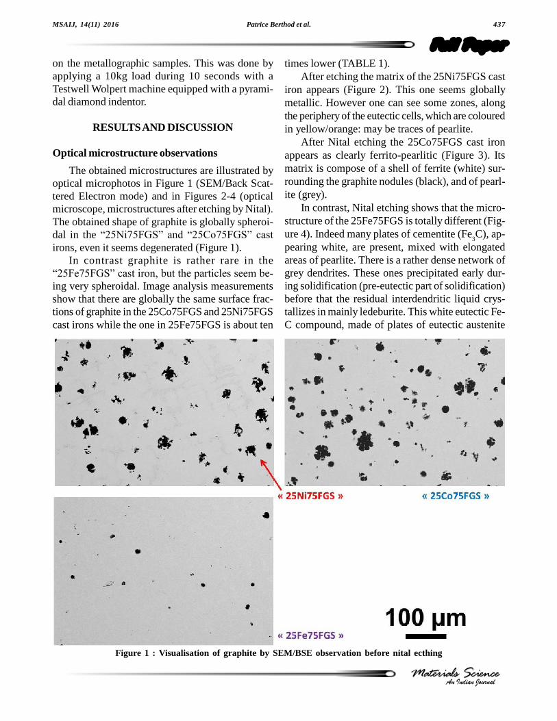
The obtained microstructures are illustrated byoptical microphotos in Figure 1 (SEM/Back Scat-tered Electron mode) and in Figures 2-4 (opticalmicroscope, microstructures after etching by Nital).The obtained shape of graphite is globally spheroi-dal in the �25Ni75FGS� and �25Co75FGS� cast
irons, even it seems degenerated (Figure 1).In contrast graphite is rather rare in the
�25Fe75FGS� cast iron, but the particles seem be-
ing very spheroidal. Image analysis measurementsshow that there are globally the same surface frac-tions of graphite in the 25Co75FGS and 25Ni75FGScast irons while the one in 25Fe75FGS is about ten
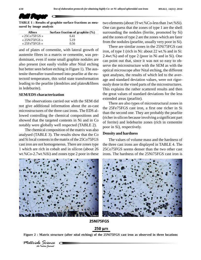
times lower (TABLE 1).After etching the matrix of the 25Ni75FGS cast
iron appears (Figure 2). This one seems globallymetallic. However one can see some zones, alongthe periphery of the eutectic cells, which are colouredin yellow/orange: may be traces of pearlite.
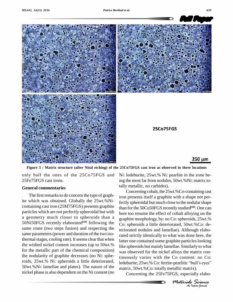
After Nital etching the 25Co75FGS cast ironappears as clearly ferrito-pearlitic (Figure 3). Itsmatrix is compose of a shell of ferrite (white) sur-rounding the graphite nodules (black), and of pearl-ite (grey).
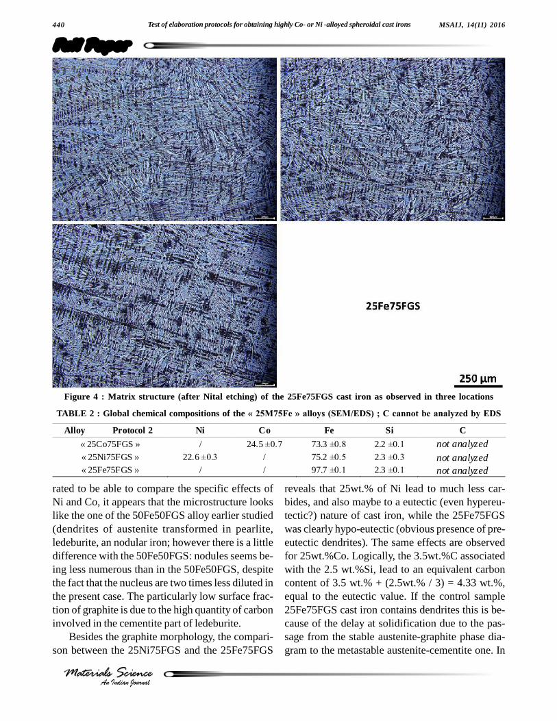
In contrast, Nital etching shows that the micro-structure of the 25Fe75FGS is totally different (Fig-ure 4). Indeed many plates of cementite (Fe
3C), ap-
pearing white, are present, mixed with elongatedareas of pearlite. There is a rather dense network ofgrey dendrites. These ones precipitated early dur-ing solidification (pre-eutectic part of solidification)before that the residual interdendritic liquid crys-tallizes in mainly ledeburite. This white eutectic Fe-C compound, made of plates of eutectic austenite
Figure 1 : Visualisation of graphite by SEM/BSE observation before nital ecthing
.438 Test of elaboration protocols for obtaining highly Co- or Ni -alloyed spheroidal cast irons
Full PaperMSAIJ, 14(11) 2016
An Indian JournalMaterials ScienceMaterials Science
Alloys Surface fraction of graphite (%) « 25Co75FGS » 6.41 « 25Ni75FGS » 5.19 « 25Fe75FGS » 0.56
TABLE 1 : Results of graphite surface fractions as mea-sured by image analysis
Figure 2 : Matrix structure (after nital etching) of the 25Ni75FGS cast iron as observed in three locations
and of plates of cementite, with lateral growth ofaustenite fibres in a matrix or cementite, was pre-dominant, even if some small graphite nodules arealso present (not easily visible after Nital etchingbut better seen before etching in Figure 1). The aus-tenite thereafter transformed into pearlite at the eu-tectoid temperature, this solid state transformationleading to the pearlite (dendrites and plates&fibresin ledeburite).
SEM/EDS characterization
The observations carried out with the SEM didnot give additional information about the as-castmicrostructures of the three cast irons. The EDS al-lowed controlling the chemical compositions andshowed that the targeted contents in Ni and in Conotably were globally well respected (TABLE 2).
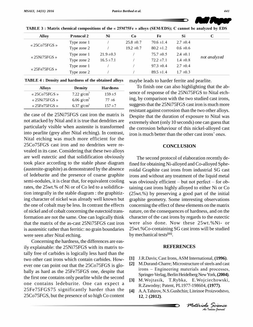
The chemical composition of the matrix was alsoanalysed (TABLE 3). The results show that the Coand Si local contents in the matrix of the 25Co75FGScast iron are not homogeneous. There are zones type1 which are rich in cobalt and in silicon (about 26wt.%Co-2.7wt.%Si) and zones type 2 poor in these
two elements (about 19 wt.%Co-less than 1wt.%Si).One can guess that the zones of type 1 are the shellsurrounding the nodules (ferrite, promoted by Si)and the zones of type 2 are the zones which are farerfrom the nodules (pearlite, usually very poor in Si).
There are similar zones in the 25Ni75FGS castiron, of type 1 (rich in Ni: about 22 wt.% and in Si:2.4wt.%) and of type 2 (poor in Ni and in Si). Onecan point out that, since it was not so easy to ob-serve the microstructure with the SEM as with theoptical microscope after Nital etching, the differentspot analyses, the results of which led to the aver-age and standard deviation values, were not rigor-ously done in the vised parts of the microstructures.This explains the rather scattered results and thenthe great values of standard deviations for the lessextended areas (pearlite).
There are also types of microstructural zones inthe 25Fe75FGS cast iron, a first one richer in Sithan the second one. They are probably the pearlite(richer in silicon because involving a significant partof ferrite) and ledeburite zones (rich in cementitepoor in Si), respectively.
Density and hardness
The values of volume mass and the hardness ofthe three cast irons are displayed in TABLE 4. The25Co75FGS seems denser than the two other castirons. The hardness of the 25Ni75FGS cast iron is
Patrice Berthod et al. 439
Full PaperMSAIJ, 14(11) 2016
An Indian JournalMaterials ScienceMaterials Science
Figure 3 : Matrix structure (after Nital etching) of the 25Co75FGS cast iron as observed in three locations
only half the ones of the 25Co75FGS and25Fe75FGS cast irons.
General commentaries
The first remarks to do concern the type of graph-ite which was obtained. Globally the 25wt.%Ni-containing cast iron (25M75FGS) presents graphiteparticles which are not perfectly spheroidal but witha geometry much closer to spheroids than a50Ni50FGS recently elaborated[10] following thesame route (two steps fusion) and respecting thesame parameters (power and duration of the two iso-thermal stages, cooling rate). It seems clear that whenthe wished nickel content increases (up to 50wt.%for the metallic part of the chemical composition)the nodularity of graphite decreases (no Ni: sphe-roids, 25wt.% Ni: spheroids a little deteriorated,50wt.%Ni: lamellae and plates). The nature of thenickel phase is also dependent on the Ni content (no
Ni: ledeburite, 25wt.% Ni: pearlite in the zone be-ing the most far from nodules, 50wt.%Ni: matrix to-tally metallic, no carbides).
Concerning cobalt, the 25wt.%Co-containing castiron presents itself a graphite with a shape not per-fectly spheroidal but much close to the nodular shapethan for the 50Co50FGS recently studied[10]. One canhere too resume the effect of cobalt alloying on thegraphite morphology, by: no Co: spheroids, 25wt.%Co: spheroids a little deteriorated, 50wt.%Co: de-teriorated nodules and lamellae). Although elabo-rated strictly identically to what was done here, thelatter one contained some graphite particles lookinglike spheroids but mainly lamellae. Similarly to whatwas observed for the nickel alloys the matrix con-tinuously varies with the Co content: no Co:ledeburite, 25wt.% Co: ferrite-pearlitic �bull�s eyes�
matrix, 50wt.%Co: totally metallic matrix).Concerning the 25Fe75FGS, especially elabo-
.440 Test of elaboration protocols for obtaining highly Co- or Ni -alloyed spheroidal cast irons
Full PaperMSAIJ, 14(11) 2016
An Indian JournalMaterials ScienceMaterials Science
Figure 4 : Matrix structure (after Nital etching) of the 25Fe75FGS cast iron as observed in three locations
Alloy Protocol 2 Ni Co Fe Si C
« 25Co75FGS » / 24.5 ±0.7 73.3 ±0.8 2.2 ±0.1 not analyzed « 25Ni75FGS » 22.6 ±0.3 / 75.2 ±0.5 2.3 ±0.3 not analyzed « 25Fe75FGS » / / 97.7 ±0.1 2.3 ±0.1 not analyzed
TABLE 2 : Global chemical compositions of the « 25M75Fe » alloys (SEM/EDS) ; C cannot be analyzed by EDS
rated to be able to compare the specific effects ofNi and Co, it appears that the microstructure lookslike the one of the 50Fe50FGS alloy earlier studied(dendrites of austenite transformed in pearlite,ledeburite, an nodular iron; however there is a littledifference with the 50Fe50FGS: nodules seems be-ing less numerous than in the 50Fe50FGS, despitethe fact that the nucleus are two times less diluted inthe present case. The particularly low surface frac-tion of graphite is due to the high quantity of carboninvolved in the cementite part of ledeburite.
Besides the graphite morphology, the compari-son between the 25Ni75FGS and the 25Fe75FGS
reveals that 25wt.% of Ni lead to much less car-bides, and also maybe to a eutectic (even hypereu-tectic?) nature of cast iron, while the 25Fe75FGSwas clearly hypo-eutectic (obvious presence of pre-eutectic dendrites). The same effects are observedfor 25wt.%Co. Logically, the 3.5wt.%C associatedwith the 2.5 wt.%Si, lead to an equivalent carboncontent of 3.5 wt.% + (2.5wt.% / 3) = 4.33 wt.%,equal to the eutectic value. If the control sample25Fe75FGS cast iron contains dendrites this is be-cause of the delay at solidification due to the pas-sage from the stable austenite-graphite phase dia-gram to the metastable austenite-cementite one. In
Patrice Berthod et al. 441
Full PaperMSAIJ, 14(11) 2016
An Indian JournalMaterials ScienceMaterials Science
the case of the 25Ni75FGS cast iron the matrix isnot attacked by Nital and it is true that dendrites areparticularly visible when austenite is transformedinto pearlite (grey after Nital etching). In contrast,Nital etching was much more efficient for the25Co75FGS cast iron and no dendrites were re-vealed in its case. Considering that these two alloysare well eutectic and that solidification obviouslytook place according to the stable phase diagram(austenite-graphite) as demonstrated by the absenceof ledeburite and the presence of coarse graphitesemi-nodules, it is clear that, for equivalent coolingrates, the 25wt.% of Ni or of Co led to a solidifica-tion integrally in the stable diagram : the graphitiz-ing character of nickel was already well known butthe one of cobalt may be less. In contrast the effectsof nickel and of cobalt concerning the eutectoid trans-formation are not the same. One can logically thinkthat the matrix of the as-cast 25Ni75FGS cast ironis austenitic rather than ferritic: no grain boundarieswere seen after Nital etching.
Concerning the hardness, the differences are eas-ily explainable: the 25Ni75FGS with its matrix to-tally free of carbides is logically less hard than thetwo other cast irons which contain carbides. How-ever one can point out that the 25Co75FGS is glo-bally as hard as the 25Fe75FGS one, despite thatthe first one contains only pearlite while the secondone contains ledeburite. One can expect a25Fe75FGS75 significantly harder than the25Co75FGS, but the presence of so high Co content
maybe leads to harder ferrite and pearlite.To finish one can also highlighting that the ab-
sence of response of the 25Ni75FGS to Nital etch-ing, by comparison with the two studied cast irons,suggests that the 25Ni75FGS cast iron is much moreresistant against corrosion than the two other alloys.Despite that the duration of exposure to Nital wasextremely short (only 10 seconds) one can guess thatthe corrosion behaviour of this nickel-alloyed castiron is much better than the other cast irons� ones.
CONCLUSION
The second protocol of elaboration recently de-fined for obtaining Ni-alloyed and Co-alloyed Sphe-roidal Graphite cast irons from industrial SG castirons and without any treatment of the liquid metalwas obviously efficient � but not perfect � for ob-
taining cast irons highly alloyed to either Ni or Co(25wt.%) by preserving a good part of the initialgraphite geometry. Some interesting observationsconcerning the effect of these elements on the matrixnature, on the consequences of hardness, and on thecharacter of the cast irons by regards to the eutecticwere also done. Now these 25wt.%Ni- or25wt.%Co-containing SG cast irons will be studiedby mechanical tests[11].
REFERENCES
[1] J.R.Davis; Cast Irons, ASM International, (1996).[2] M.Durand-Charre; Microstructure of steels and cast
irons � Engineering materials and processes,
Springer-Verlag, Berlin Heidelberg New York, (2004).[3] M.Wojtasik, T.Rybka, E.Wojciechowski,
R.Zawodny; Patent, PL1977-198604, (1977).[4] A.A.Tahirov, N.S.Gushchin; Liteinoe Proizvodstvo,
12, 2 (2012).
TABLE 3 : Matrix chemical compositions of the « 25M75Fe » alloys (SEM/EDS); C cannot be analyzed by EDS
TABLE 4 : Density and hardness of the obtained alloys
Alloys Density Hardness
« 25Co75FGS » 7.22 g/cm3 159 ±5
« 25Ni75FGS » 6.06 g/cm3 77 ±6
« 25Fe75FGS » 6.37 g/cm3 157 ±7
Alloy Protocol 2 Ni Co Fe Si C
« 25Co75FGS » Type zone 1 / 25.8 ±0.7 70.6 ±1.4 2.7 ±0.4
not analyzed
Type zone 2 / 19.2 ±0.7 80.2 ±1.2 0.6 ±0.6
« 25Ni75FGS » Type zone 1 21.9 ±0.3 / 75.7 ±0.5 2.4 ±0.1
Type zone 2 16.5 ±7.1 / 72.2 ±7.1 1.4 ±0.8
« 25Fe75FGS » Type zone 1 / / 97.3 ±0.4 2.7 ±0.4
Type zone 2 / / 89.5 ±1.4 1.7 ±0.3
.442 Test of elaboration protocols for obtaining highly Co- or Ni -alloyed spheroidal cast irons
Full PaperMSAIJ, 14(11) 2016
An Indian JournalMaterials ScienceMaterials Science
[5] Y.Z.Liu, L.L.Sun, C.A.Li, J.Xiong, Y.F.Wang;Zhongnan Daxue Xuebao, Ziran Kexueban, 43(10),3832 (2012).
[6] J.C.Morrison; Giesserei-Praxis, 12, 483 (1998).[7] C.Zhou; Patent, CN 2015-10341175, (2015).[8] X.Hu, Z.Wang, K.Huang, F.Li, P.Li; Patent, CN
2010-10177246, (2010).
[9] K.Meridja, P.Berthod, E.Conrath; Materials Science: An Indian Journal, 14(4), 130 (2016).
[10] K.Meridja, P.Berthod, E.Conrath; Materials Science: An Indian Journal, 14(4), 139 (2016).