mechanical properties of electron beam welded spheroidal graphite cast iron … · ·...
TRANSCRIPT

Mechanical Properties of Electron Beam Welded Spheroidal Graphite Cast Iron
and Mild Steel Welded Joints*
Shinichi Sekiguchi1 and Fumio Shibata2
1Precision Machinery Company, Ebara Corporation, Fujisawa 251-8502, Japan2College of Science and Technology, Nihon University, Funabashi 274-8501, Japan
Direct welding between spheroidal graphite cast iron (FCD700) and mild steel (SS400) was conducted using electron beam welding tostudy the microstructure and the mechanical properties of the welds.
Results showed that one-pass welding yielded an over-hardened fusion zone exhibiting acicular martensite structure (815 HV) with cracksand porosities. Two-pass welding contained fewer porosities. Both one-pass and two-pass welding displayed acicular martensite and ledeburitewithin the microstructure of spheroidal graphite cast iron in heat-affected zone. The tensile strength of both one-pass and two-pass welded jointswas lower than that of mild steel base metals. These joints ruptured at the fusion zone or the mild steel bond. However, two-pass welded jointsdemonstrated tensile yield stress values greater than or equal to those of mild steel base metals. Hardening of the fusion zone and the heat-affected zone of spheroidal graphite cast iron made the impact strength values of two-pass welded joints conspicuously lower than those of thespheroidal graphite cast iron base metal. The fatigue strength of two-pass welded joints almost equaled that of mild steel base metal, with afatigue limit of 209 MPa. [doi:10.2320/matertrans.F-M2011820]
(Received February 14, 2011; Accepted June 2, 2011; Published September 25, 2011)
Keywords: spheroidal graphite cast iron, mild steel, electron beam welding, number of passes, microstructure, mechanical properties
1. Introduction
Compared to other cast irons, spheroidal graphite cast ironhas superior mechanical properties, and, in recent years,has been widely applied in the fabrication of mechanicalstructural components and cast iron pipe. In order to achievehigh functionality and to improve cost efficiency, compo-nents made by welding of spheroidal graphite iron casting tosteel parts has been examined.1) For example, industrialpump casings of spheroidal graphite cast iron typically areattached to steel pipes with mechanical fasteners (bolts).Welding of these casings to the pipes may reduce fluidleakage and reduce costs by simplifying the assembly.
However, spheroidal graphite cast iron is difficult toweld,2) and fusion welding spheroidal graphite cast iron tosteel is even more challenging. Therefore, the application ofwelding these two materials to each other is limited. Weldingis difficult because the welding process involves the rapidfusion and solidification of high-carbon spheroidal graphitecast iron, which results in the formation of ledeburite in theweld zone. The ledeburite in the weld can cause weld defects,such as cracks, due to embrittlement and significantly reducethe mechanical properties of the welded joint.
Various authors have reported on fusion welding betweenspheroidal graphite cast iron and steel and, examined thewelding microstructure and joint performance obtained byshielded metal arc welding,3,4) tungsten inert gas welding,5–7)
metal active gas welding,4) and gas welding.4) In addition,some studies,8–20) including one by A. Matting, et al., havereported on electron beam welding, which can provide higherenergy density than other welding methods and minimize thethermal effect on base metals, to welding between gray castirons or spheroidal graphite cast irons. For the details of
electron beam welding between spheroidal graphite cast ironand mild steel, only one report (Hatate, et al.21)) is available,stating that mild steel was butt welded to a 15 mm thick,spheroidal graphite cast iron plate using insert metalcomprising spheroidal graphite cast iron alloyed with 35%nickel.
Therefore, this present study examines the welding micro-structure and joint strength obtained by direct, square butt,electron beam welding of spheroidal graphite cast iron tomild steel.
2. Experimental Procedures
Table 1 shows the chemical compositions and mechanicalproperties of the base metals. Spheroidal graphite cast iron(equivalent to FCD700, JIS G5502) and mild steel (equiv-alent to SS400, JIS G3101) were used as base metals. Themicrostructure and hardness of each base metal are shown inFig. 1. The microstructure of the spheroidal graphite castiron is composed mainly of pearlite but also contains aslight amount of ferrite around the graphite; its hardness is246HV0.3. The microstructure of the mild steel is composedof pearlite and ferrite; its hardness is 137 HV0.3.
Welding tool was a 6 kW high-voltage, high-vacuumelectron beam welding machine (all vacuum type). Immedi-ately before welding, the base metals were demagnetized,and the butt surface was degreased with methyl ethyl ketone.Then, the base metals were square butt welded by irradiatingan electron beam onto the butt surface from above (down-ward penetration welding), as shown in Fig. 2. The dimen-sions of the base metals were t18� 200� 200 mm.
Test specimens were joined with one-pass welds andtwo-pass welds. Table 2 shows the welding conditions. InTable 2, the ab value13) refers to an active beam parameter(ab ¼ D0=DF, D0: Objective Distance and DF: FocalDistance).
*This Paper was Originally Published in Japanese in J. JFS 82 (2010) 478–
483.
Materials Transactions, Vol. 52, No. 10 (2011) pp. 1920 to 1925#2011 Japan Foundary Engineering Society

The welding microstructure was microscopically observedby cutting the bead transversely, polishing the cut surface,and then etching the surface with 4% nital. Furthermore, thechemical analysis of the fusion zone and the EPMA lineanalysis of the welding were conducted.
For material tests, a Micro Vickers hardness tester (with aHV of 0.3) was used to measure the hardness at 0.1 mm pitchin the weld cross section. Tensile tests (using the testspecimens No. 4, defined by JIS Z2201 ‘‘Test pieces for
tensile test for metallic materials’’), impact tests (Non-notch,10� 10� 55 mm, at test temperatures of 77 to 373 K), androtary bending fatigue tests (at a rotational speed of3000 min�1) were carried out to determine the mechanicalproperties of the welded joints. The surface of the weldedjoints fracture in tension was observed with a scanningelectron microscope (SEM).
3. Results and Discussion
3.1 Microstructure and hardness distribution of thewelds
Figure 3 shows the microstructures of the one-pass andtwo-pass welds. The microstructure in the one-pass weldingfusion zone exhibits acicular martensite and fine cracks.Compared to the one-pass welding, the microstructure in thetwo-pass welding fusion zone exhibits coarse acicularmartensite, but no cracks. Slower cooling of two-pass welddue to the slightly wider fusion zone of two-pass welding(one-pass welding: 0.62 mm and two-pass welding: 0.78 mm)may be partly responsible for this difference. In the fusionzone near the bond of spheroidal graphite cast iron, the two-pass welding shows a coarser acicular microstructure than theone-pass welding. In the fusion zone near the bond of mildsteel, the appearance of acicular martensite in the one-passwelding is similar to that in the two-pass welding.
The microstructure of spheroidal graphite cast iron in theheat-affected zone exhibits martensite and ledeburite in thevicinity of the graphite near the bond. For both the one-passwelding and the two-pass welding, the microstructure of mildsteel in the heat-affected zone exhibits pearlite.
Table 3 shows the results of the chemical analysis of thefusion zone. The carbon content in the fusion zone is nearlyidentical 0.85% for the one-pass welding and 0.86% for thetwo-pass welding. The silicon content is slightly higher in thetwo-pass welding 0.57% for one-pass vs. 0.83% for the two-pass welding. The contents of manganese, phosphorous,sulfur and magnesium are almost the same regardless of thenumber of passes. These similar chemical compositionssupport the theory that the slower cooling of two-pass weld,rather than chemistry, is responsible for the coarser micro-structure in the two-pass fusion zone.
Figure 4 shows the results of the EPMA line analysis of thetwo-pass welding. In the fusion zone, there are concentrationgradients of iron, carbon, silicon and manganese withinapproximately 200 mm of the bond in the mild steel. At thebond of spheroidal graphite cast iron, small concentrationgradients of silicon and manganese are observed, but themagnitude and width of variation are smaller than thegradients at the bond of mild steel.
In the two-pass welding fusion zone, the microstructurenear the bond of spheroidal graphite cast iron is differentfrom that near the bond of mild steel, possibly because of thedifference in fusion zone composition.
Figure 5 shows the hardness distributions of the one-passwelding and the two-pass welding. The hardness of the one-pass welding fusion zone is 775 to 849 HV, averaging815 HV, and is significantly higher than that of the spheroidalgraphite cast iron base metal (approximately 240 HV). Thehardness of the two-pass welding fusion zone is 387 to
(a) FCD700 (b) SS400
246HV 137HV
100µm 100µm
Fig. 1 Microstructure and Vickers hardness of base metals.
200
FCD700 SS400
Electronbeam
Weldingdirection
100 100
18
(unit:mm)
Fig. 2 Joint configuration of butt welding.
Table 2 Welding conditions by butt welding.
Number of passes One-pass and Two-pass
Vacuum 1:33� 10�2 Pa
Acceleration voltage 150 kV
ab value13Þ 0.9
Beam current 30 mA
Welding speed 600 mm/min
Welding heat input 4500 J/cm
Table 1 Chemical compositions and mechanical properties of base metals.
MaterialsChemical composition (mass%)
C Si Mn P S Mg Cu Cr C.E.
Base FCD700 3.75 2.67 0.24 0.02 0.004 0.043 0.62 0.037 4.65
metal SS400 0.15 0.15 0.69 0.012 0.007 — — — —
TensileElongation
Impact Fatigue
Materials strength(%)
value limit
(MPa) (J/cm2) (MPa)
Base FCD700 790 6 19.6 261
metal SS400 434 38 419 209
Mechanical Properties of Electron Beam Welded Spheroidal Graphite Cast Iron and Mild Steel Welded Joints 1921

820 HV, averaging 566 HV, and is lower than that of the one-pass welding fusion zone. The coarser microstructure in thetwo-pass welding fusion zone may underlie this difference inhardness. The maximum hardness of the two-pass weldingfusion zone is 820 HV, is near the bond of mild steel and isalmost equal to the average hardness of the one-pass weldingfusion zone (815 HV). This similarity in hardness may resultfrom the consistent, acicular martensite microstructure in thefusion zone near the bond of mild steel is regardless of thenumber of weld passes.
The maximum hardness of spheroidal graphite cast iron inthe heat-affected zone is 869 HV for the one-pass weldingand 823 HV for the two-pass welding, representing asignificant increase in the hardness for both weld types.The maximum hardness of mild steel in the heat-affectedzone is 465 HV for the one-pass welding and 362 HV for thetwo-pass welding, indicating a decrease in hardness as thenumber of passes increases.
Table 3 Result of chemical compositions of fusion zones by butt welding
(mass%).
Butt welding C Si Mn P S Mg
One-pass 0.85 0.57 0.68 0.02 <0:01 0.01
Two-pass 0.86 0.83 0.60 0.02 <0:01 0.01
FCD700
Fusionzone
SS400
Position ofobservation
FCD700 SS400Fusion zone
(a) one-pass welding
Crack
(b) two-pass welding
200µm
200µm
FCD700 SS400Fusion zone
Bond of FCD700 by one-passwelding
50µ m 50µm
Bond of SS400 by one-passwelding
FCD700 SS400Fusion zone Fusion zone
50µm
Bond of SS400 by two-passwelding
Bond of FCD700 by two-passwelding
50µm
FCD700 SS400Fusion zone Fusion zone
Fig. 3 Microstructure of butt welds.
Fig. 4 Result of line analysis by butt welding. Note: 1) Two-pass welding.
Fig. 5 Vickers hardness distribution of butt welds.
1922 S. Sekiguchi and F. Shibata
3.2 Mechanical properties of the welded jointsFigure 6 compares the tensile strength and elongation of
the base metals, the one-pass welded joint, and the two-passwelded joint. The welded joint tensile test was made on fourtest specimens for each weld type. The tensile strength ofthe one-pass welded joints ranged from 199 to 256 MPa,averaging 240 MPa. The tensile strength of the two-passwelded joints varied from 297 to 329 MPa, averaging311 MPa. Thus, the average strength of the two-pass weldedjoint is 71 MPa higher than that of the one-pass welded joint;for all four test specimens of the two-pass welded joint, thetensile strength is equal to or greater than the yield stress ofthe mild steel base metal. The joint elongation of the two-pass welding is also greater than that of the one-pass welding:0.20 to 0.61% for the one-pass welding and 1.60 to 1.97%for the two-pass welding, averaging 0.40% and 1.74%,respectively.
Figure 7 shows the tensile fracture surfaces and breakingpositions of the one-pass and two-pass welded joints. Thetensile breaking position of the one-pass welded joint islocated in the fusion zone with coarse porosities observed onthe fracture surface. The average porosity area ratio of thefour test specimens on the tensile fracture surface of the one-pass welded joint10) is about 12%. The porosities probably areformed by the generation of CO gas through chemicalreactions in the molten metal.13) The tensile breaking positionof the two-pass welded joint is located in the fusion zone andthe bond of mild steel. A small number of fine porosities areobserved on the fractured surface, and the size of porosities issignificantly smaller than that in the one-pass welding. Thearea ratio of porosity on the tensile fracture surface of the
two-pass welded joint is about 0.5%. For the two-passwelding, this fact suggests that the number of porosities in thefusion zone decreases with the less rapid cooling of the fusionzone and the facilitation of gas release through the stirring ofthe molten metal.13)
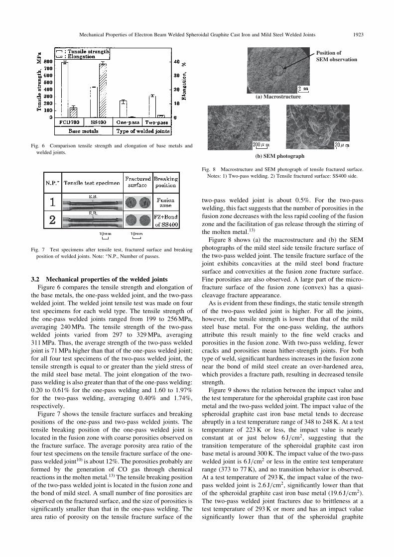
Figure 8 shows (a) the macrostructure and (b) the SEMphotographs of the mild steel side tensile fracture surface ofthe two-pass welded joint. The tensile fracture surface of thejoint exhibits concavities at the mild steel bond fracturesurface and convexities at the fusion zone fracture surface.Fine porosities are also observed. A large part of the micro-fracture surface of the fusion zone (convex) has a quasi-cleavage fracture appearance.
As is evident from these findings, the static tensile strengthof the two-pass welded joint is higher. For all the joints,however, the tensile strength is lower than that of the mildsteel base metal. For the one-pass welding, the authorsattribute this result mainly to the fine weld cracks andporosities in the fusion zone. With two-pass welding, fewercracks and porosities mean hither-strength joints. For bothtype of weld, significant hardness increases in the fusion zonenear the bond of mild steel create an over-hardened area,which provides a fracture path, resulting in decreased tensilestrength.
Figure 9 shows the relation between the impact value andthe test temperature for the spheroidal graphite cast iron basemetal and the two-pass welded joint. The impact value of thespheroidal graphite cast iron base metal tends to decreaseabruptly in a test temperature range of 348 to 248 K. At a testtemperature of 223 K or less, the impact value is nearlyconstant at or just below 6 J/cm2, suggesting that thetransition temperature of the spheroidal graphite cast ironbase metal is around 300 K. The impact value of the two-passwelded joint is 6 J/cm2 or less in the entire test temperaturerange (373 to 77 K), and no transition behavior is observed.At a test temperature of 293 K, the impact value of the two-pass welded joint is 2.6 J/cm2, significantly lower than thatof the spheroidal graphite cast iron base metal (19.6 J/cm2).The two-pass welded joint fractures due to brittleness at atest temperature of 293 K or more and has an impact valuesignificantly lower than that of the spheroidal graphite
Fig. 6 Comparison tensile strength and elongation of base metals and
welded joints.
Fig. 7 Test specimens after tensile test, fractured surface and breaking
position of welded joints. Note: �N.P., Number of passes.
Position of SEM observation
(a) Macrostructure
(b) SEM photograph
Fig. 8 Macrostructure and SEM photograph of tensile fractured surface.
Notes: 1) Two-pass welding. 2) Tensile fractured surface: SS400 side.
Mechanical Properties of Electron Beam Welded Spheroidal Graphite Cast Iron and Mild Steel Welded Joints 1923

cast iron base metal. Thus, it fails to achieve good jointperformance.
Figure 10 shows the fatigue breaking position of the two-pass welded joint. Except for one specimen that did notfracture due to fatigue, the fatigue breaking position of thetwo-pass welded joint is located in the mild steel base metalfor five test specimens and in the fusion zone for two testspecimens. The test specimens fractured in the fusion zoneexhibit porosities on the fracture surface.
Figure 11 shows the S-N curve of the two-pass weldedjoint. The rotating bending fatigue limit of the two-passwelded joint is 209 MPa and almost equal to that of the mildsteel base metal. Since the two-pass welded joint has anaverage tensile strength of 310 MPa, the fatigue limit/tensilestrength ratio of the joint is approximately 0.67, which isgreater than that of the mild steel base metal (approximately0.48). Except for the test specimens with porosities present inthe fusion zone, the fracture occurred mainly in the mild steelbase metal at cyclic stresses of 215 to 273 MPa. At a cyclicstress of 232 MPa, for example, the specimens fractured in
the mild steel base metal have the fatigue strength at 6:2�105 cycles, while the test specimens with porosities present inthe fusion zone have the fatigue strength at 1:6� 105 cycles.
For the two-pass welded joint, the fatigue strength of thetest specimens with no porosities present in the fusion zone isalmost equal to that of the mild steel base metal. Thus, theover-hardened portion of the fusion zone or spheroidalgraphite cast iron in the heat-affected zone had little negativeeffect on the fatigue strength.
However, the porosities in the fusion zone cause stressconcentrations there, resulting in development of crack, andmaterially decreasing fatigue strength.16)
4. Conclusions
The microstructure and strength of electron beam weldedjoints between spheroidal graphite cast iron and mild steelwere examined. The conclusions are summarized below.(1) In all cases, a large part of the microstructure in the
fusion zone exhibited acicular martensite. The acicularmartensite of the two-pass welds was coarser than thatof the one-pass welds. In the two-pass fusion zone, themicrostructure near the bond of spheroidal graphite castiron exhibits coarse acicular martensite and that nearthe bond of mild steel has cementite. These micro-structures differed in both.
(2) A significant increase in hardness was apparent in boththe fusion zone (one-pass welding: 815 HV on averageand two-pass welding: 566 HV on average) and theheat-affected zone of spheroidal graphite cast iron (one-pass welding: 869 HV at the maximum and two-passwelding: 823 HV at the maximum).
(3) For all welded joints, the tensile strength was lower thanthat of the mild steel base metal. In addition, thebreaking positions were located in the fusion zone andat the bond with mild steel. The two-pass welded jointexhibited a tensile strength equal to or greater than theyield stress of the mild steel base metal; its averagetensile strength and average elongation were 311 MPaand 1.74%, respectively.
(4) The impact value of the two-pass welded joint was2.6 J/cm2 at a test temperature of 293 K and signifi-cantly lower than that of the spheroidal graphite castiron base metal (19.6 J/cm2).
(5) The fatigue strength of the two-pass welded joint wasalmost equal to that of the mild steel base metal. The
Fig. 9 Relation between impact value and testing temperature of base
metal and welded joints.
Fig. 10 Test specimens after fatigue test and breaking position of welded
joints by butt welding. Note: 1) Two-pass welding.
Fig. 11 S-N curves of base metals and welded joints.
1924 S. Sekiguchi and F. Shibata

rotating bending fatigue limit of the two-pass weldedjoint was 209 MPa, meaning that the fatigue limit/tensile strength ratio was approximately 0.67 andgreater than that of the mild steel base metal.
Acknowledgments
The authors are grateful to the research students from theDepartment of Mechanical Engineering and the Departmentof Precision Machinery Engineering, College of Science andTechnology, Nihon University, for their kind cooperation inthe experiments of this study.
REFERENCES
1) K. Asano and T. Noguchi: J. JFS 78 (2006) 98.
2) Jpn. Weld. Soc.: Yousetsu�Setsugou binran (Maruzen, 1990) p. 860.
3) T. E. Kihlgren and H. C. Waugh: Welding J. 32 (1953) 947.
4) N. Fujii, J. Takahashi, H. Suzuki and K. Yasuda: Q. J. Jpn. Weld. Soc.
23 (2005) 302.
5) S. Hiratuka, H. Horie, M. Nakamura, T. Konishiki, M. Aonuma and
T. Kobayashi: J. JFS 70 (1998) 860.
6) M. Aonuma, S. Hiratuka, H. Horie, M. Nakamura and T. Konishiki:
J. JFS 72 (2000) 478.
7) S. Hiratuka, H. Horie, T. Konishiki and M. Nakamura: J. JFS 78 (2006)
112.
8) A. Matting and K. Seifert: Schweiben und Schneiden 20 (1968) 266.
9) F. Shibata: J. JFS 69 (1997) 391.
10) F. Shibata, S. Ando and N. Fujisaki: J. Jpn. Weld. Soc. 51 (1982) 748.
11) F. Shibata and S. Ando: Trans. JWS 14 (1983) 11.
12) S. Ando and M. Ookubo: Q. J. Jpn. Weld. Soc. 2 (1984) 308.
13) F. Shibata: IMONO 56 (1984) 532.
14) F. Shibata: IMONO 59 (1987) 478.
15) K. Tagashira, S. Kamoda and T. Hashimoto: J. S. Precision Eng. 53
(1987) 110.
16) F. Shibata and Y. Uchida: IMONO 60 (1988) 666.
17) F. Shibata: Trans. JWS 22 (1991) 34.
18) F. Shibata: Trans. JWS 22 (1991) 40.
19) F. Shibata: Trans. JWS 22 (1991) 90.
20) F. Shibata: IMONO 64 (1992) 9.
21) M. Hatate, T. Shiota, Y. Nagasaki, N. Abe, M. Amano and T. Tanaka:
J. High Temp. Soc. 33 (2007) 313.
Mechanical Properties of Electron Beam Welded Spheroidal Graphite Cast Iron and Mild Steel Welded Joints 1925