damping properties of selected steels and cast irons
TRANSCRIPT
iRIi906s1
PLEASE DO NOT REMOVE FRCM LIBRARY
Bureau of Mines Report of Investigations/1987
Damping Properties of Selected Steels and Cast Irons
By A. Visnapuu, R. W. Nash, and P. C. Turner
UNITED STATES DEPARTMENT OF THE INTERIOR
Report of Investigations 9068
Damping Properties of Selected Steels and Cast Irons
By A. Visnapuu, R. W. Nash, and P. C. Turner
UNITED STATES DEPARTMENT OF THE INTERIOR Donald Paul Hodel, Secretary
BUREAU OF MINES Robert C. Horton, Director
Library of Congress Cataloging in Publication Data:
Visnapuu, A. (Aarne) Damping properties of selected steels and cast irons.
(Report of investigations; 9068)
Bibliography: p. 14-15.
Supt. of Docs. no.: I 28.23: 9068.
1. Mining machinery- Vibration. 2. Steel-Testing. 3. Cast·iron-Testing. 4. Damping (Mechanics). I. Nash, R. W. (Robert W.). II. Turner, P. C. Ill. Title. IV. Series: Report.of investigations (United States. Bureau of Mines) ; 9068.
TN23.U43 [TN345] 622 s [620.3] 86-600351
CONTENTS
Abstract .......•. .............................•..•....•. 0 ••••••••• €I ••••••••• • ••
Introduction ................................................. • ••• .. .. . .. ....... Previous investigations •.•.••••••.••••......••••.•••.••••••• •• •• • • •• ••••••••• Purpose of this investigation ................•...............................
Experimental procedure ......................••.•••.•••................•..•••••. Results and discussion ......................................................•..
Steels ................................................ ...•... .. ..• . .••... . ... Cast irons •••••
Conclusions •..•.. References .......................•...••...•••.•. ••..•.. • •••• •••...••••••••..•••
1. 2.
3. 4. 5.
1. 2.
ILLUSTRATIONS
Microstructures of carbon and alloy steels ••••••....•.•••....••••..•.•••••• Specific damping capacity of carbon and alloy steels as a function of stress ...........•................................................ ... .....
Microstructures of spheroidized heat-treated carbon and alloy steels •••• •.• Microstructures of cast lrons ..••...••••.•.••• • ••• • ••••• •• ••••• ••.• .•• .•••• Specific damping capacity of cast irons as a function of stress ••• • • •••••••
Specific Specific
damping da,mping
TABLES
capacities and microstructures of car.bon and alloy steels. capacities of spheroidized heat-treated carbon and alloy
steels ...... . . .. ... ..... ..........•••...........................•......... 3. Specific damping capacities and graphite morphologies of selected cast
irons ............................................... .. .......... . ....... . . 4. Composition and mechanical properties of selected cast irons ..••••. • .••••••
1 2 2 3 3 4 4
10 14 14
5
7 8
11 13
7
9
10 10
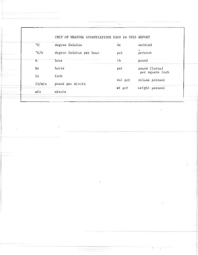
t-UNIT OF MEASURE ABBREVIATIONS USED IL'l" THIS REPORT
°c degree Ce lsius Oe oersted
°C/h degree Celsius pe r hour pct percent
h hour lb pound
Hz hertz psi pound (force) per square inch
in inch vol pet 'volume percent
lb/min pound pe r minut e wt pet Feight percent
min mi nute
[)AMPING PROPERTIES OF SELECTED STEELS AN D CAST IRONS
By A. Visnapuu,1 R. W. Nash,2 and P. C. Turner3
ABSTRACT
Excessive noise and high vibration are inherently associated with equipment used in the mining, extraction, and processing of mineral resources. High vibration degrades structural components, often leading to catastrophic failure and loss of productivity, and excessive noise can result in permanent hearing loss.
In order to foster efficient utilization of the Nation's mineral resources and minimize occupational hazards associated with mineral processing, the Bureau of Mines investigated the relationship between the microstructures of carbon and alloy steels and cast irons and their damping capacities (ability to absorb vibration). Researchers measured damping capacity and other properties and investigated the effects of carburizing, spheroidizing, and annealing.
The investigators found that in carbon and alloy steels, rounded colonies of fine-grained pearlite in a ferrite matrix correlate well with low damping capacity. Steel microstructures that exhibit sharp-faceted pearlite in ferrite matrix and partially or fully spheroidized cementite in ferrite show considerably higher damping. In cast irons, the lowest damping capacity is associated with nodular graphite microstructure, and the specific damping capacity (SDC) increases as the graphite microstructure progresses from nodular to compacted to flake. Predominant ferrite in cast irons is also associated with good damping. SDC data are presented for selected carbon and alloy steels and cast irons.
'Research physicist. 2p hysical science technician. 3Metallurgist. Rolla R esearch Center, Bureau of H.ines, Rolla, MO.
L
2
INTRODUCTION
In recent years, the vibration damping inherent in engineering materials has gained importance as a design consideration, in addition to the more commonly considered mechanical properties such as tensile and yield strength, ductility~
he.rdness ., and. toughness . - The need for improved damping properties, without undue sacrifice of other properties that determine durability, is the result of increased demand for lower product, workplace, and environmental noise, and the realization that reduced vibration can proloM the service life of machinery and equipment. One fundamental way to improve damping properties is to use relatively high-damping materlalS:- erf the available structural alloy systems, only ferrous alloys appear to be cheap enough in intrinsic material and processing cost to be economically feasible.
PREVIOUS INVESTIGATIONS
Previous investigations have developed a variety of damping materials an methods, and some have been developed to the point of commercial availability. Manganese-copper binary alloys ranging from 50 to 80 wt pct Mn, both cast (1)4 and powder-metallurgy consolidated (I), exhibit SDC's in the range 20 to 25 pct at a stress of 5,000 psi. In addition to high damping capacity, these alloys have useful mechanical properties comparable to those of mild steel. High damping is obtained by solution heat treatment followed by aging to precipitate an intermetallic phase.
Other Mn-Cu-based damping alloys with minor metal additions have been developed. Sonoston5 alloy has the composition Cu-54 Mn-4.25 Al-3 Fe-l.5 Ni (1). The damping alloys Incramute I and II, developed by the International Copper
4Underlined numbers in parentheses refer to itp.ms in the list of references at the end of this report.
5Reference to specific products does not imply endorsement by the Bureau of Mines.
Research Association, consist of Cu-40 Mn-2 Al and Cu-40 Mn-2 Al-2 Sn, respectively (i-i) 0 They are commercially available.
While the Mn- Cu alloys possess excel,,, lent vibration damping and good mechanical properties , they have some disadvantages: (1) The cost of compo_n,ent e_tals and fabrication is high, and (2) damping capacity decreases with temperature. Other low-strength materials are adequate for many applications. The Sonoston and Incramute I alloys lose their damping above 75 0 C. Damping in Incramute II disappears above about 125 0 C. The higher damping transition temperature for Incramute II is due to the tin addition, which apparently affects precipitate stability (i).
A ferromagnetic iron-base alloy containing chromium and aluminum, developed in Japan, is reported to have high damping up to 350 0 C (2). A drawback with this alloy is that damping capacity is dependent on an external magnetic field.
appIiea-magOe. Another
by 'ivestinghouse Electric Corp., has good damping and excellent mechanical properties; however, its composition, Co-22.5 Ni-l.8 Ti, is high in the critical metals cobalt and nickel, which must be imported, meaning that its use must be restricted to special applications.
Alternate approaches for damping commonly use shock absorbers, shock mounts, constrained-layer damping, and bonded-on materials to isolate, increase mass, or increase stiffness. In many instances, these measures provide the most practical and economic damping method. Sometimes they are only partly effective but are used because engineering materials with the requisite damping and physical properties are not available or are costprohibitive. Some aluminum alloys and brass have SDC's on the order of 0.01 to 1 pct at stress levels below 3,500 psi.
Of the iron-'based materials> gray cast irons exhibit excellent damRing owing to energy dissipation resulting from high
stLess concent r ations around the embrittling graphite flakes (~); however, us~ful toughness is practically nil. This has limited the use of gray cast irons to applications where toughness is not a major factor. Ductile irons have nodular graphite dispersed in continuous matrices similar to those of steel, which imparts toughness and ductility and permits plastic deformation, but markedly reduces damping -capacity relative to that of gray cast irons. Ductile irons are actually a family of materials; they differ as a result of factors such as composition, section size, cooling rate, and- -he-at tr-e-a-t-men-t, and can be proce-ss-ecl into a wide range of properties (~-lQ). Compared with steels, ductile irons have generally inferior ductility, weldability, and impact and fatigue resistance, but superior castability, machinability, wear and corrosion resistance, and damping capacity. Compacted graphite cast irons have structures that are intermediate in terms of form, to the flakes of gray cast iron and the nodules of ductile iron. Graphite in compacted graphite cast i ron has r ounded tips, relative to the flakes in gray cast iron, but is continuous in the sense that flakes are continuous in the matrix (actually they are relatively long-range colonies on a microscopic scale). This graphi te morp,hology, which may be associated with some graphite tending toward flakes or nodules, imparts certain desirable
3
prope r ties relative to gray cast i r on , such as increased ductility and tensile and yield strength.
Steels tend to exhibit low SDC's in comparison with those of the cast irons, which is attributable to the absence of free graphite. Damping in steels increases somewhat with the carbon content, and spheroidization tends to further enhance damping capacity.
PURPOSE OF THIS INVESTIGATION
This investigation was conducted as part of the Bureau's research effort to C-0nserve resources and increase productivity through improved performance and develop safer materials. Baseline SDC's were determined for representative industrial and structural carbon steels and cast irons and were correlated to the respective carbide and graphite microstructures. Selected materials were subjected to carburizing, spheroiclizing, and annealing heat treatments to delineate their influence on damping and other properties. The data reported is intended to supplement the meager damping capacity information available on these materials and to serve as a benchmark against which ongoing developmental work can be compared. The ultimate goal is to use this information to produce new iron-base high-damping materials or to alter the structure of existing materials to improve damping.
EXPERIMENTAL PROCEDURE
The carbon and alloy steels investigated in this study were of the following AISI grades: 1020, 1035, 1045, 1095, 1117, 1144, 4140, and 4340. The steels were selecl:ea as being representaEive of commercially available steels. Specimens for measuring damping capacity and oiher physical properties were prepared from commercial hot-rolled rod stock that varied in diameter from 3/4 to 2-1/4 in. In addition to SDC evaluation in the as-received condition, measurements were made after selective heat treatment to alter the carbide morphology. Damping capacity specimens of the 1045, 1095,
1144, 4140, and 4340 steels were carburized for 3 h at 925 0 C using sodium carbonate, barium carbonate, and charcoal. The 1045, 1144, 4140, and 4340 steels were then given a spheroidizing heat treatment by holding at 750 0 C for 6 h, cooling at , 30 0 C/h to 650 0 C, and holding at 650 0 C for 36 h. The 1095 steel was spheroidized by holding at 715 0
C for 6 h, followed by a 36-h hold at 680 0 C.
Cast irons were prepared il1 60- and 120-lb heats by induction melting in magnesium oxide crucibles. The temper-ature was monitored with Pt, Pt-10 Rh
4
thermocouples in protection tubes, and carbon equivalent was determined from the temperature of eutectic solidification. Heats were constituted to have nominally 2.4 to 3.0 pct Si, carbon equivalent from 4.2 to 4.8 pct, and 0.3 pct Mn. Magnesium or mischmetal (57 pct Ce) was added as a nodulizing agent, and titani.um_ oI_ zircO-nium was added separately as a denodulizing agent. Some of the 60-lb heats were made using a single additive containing both magnesium and titanium. All the ~ast iron heats were cast in standard keel-block molds (core sand) with I-in legs. Ductile iron castings were ferritize-annealed by heating in helium for 3 h at 900 0 C, followed by cooling to and holding at 695 0 C for 6 h.
Tensile specimens with a standard 0.5-in diam (~) were prepared from keelblock legs and tested on a tensile test machine at a 4,800-lb/min load rate to yield. Tensile strength, 0.2-pct offset yield strength, and elongation (percent) were calculated.
Chemical analyses and microscopy were conventional. Carbon content was deter mined from pin castings and analyses of other elements from drillings. Microscopy specimens were polished with
diamond abrasive and etched in nital (2 vol pct HN03 and 98 vol pct C2 ~ OH).
SDC was measured with a torsion pendulum designed and assembled by the Bureau (1l-11). SDC is defined as
where ~ is the initial amplitude of torsional vibration at reso_nan_~e and __ Ar, is the amplitude n cycles after ~.
Typical resonance frequencies for these specimens varied from 7 to 15 Hz due to differences in modulus of elasticity. The damping capacity is independent of f req uency and mode of vi bra t -i6n (J). Although the results are reported as SDC, other descriptors of damping, such as loss factor, fraction of critical damping, logarithmic decrement, and halfpower bandwidth, can be readily obtained from the data. The SDC measurements were made on shouldered specimens 4.5 in long with a 2.5-in gauge length and a 0.188-in reduced diameter. The curves of SDC versus torsional stress (presented in the next section) are digitally filtered curves derived from t h e ~ or more snc values obtained for each specimen. The curves were generated by a sliding, 5-point curve-fitting computer routine.
RESULTS AND DISCUSSION
STEELS
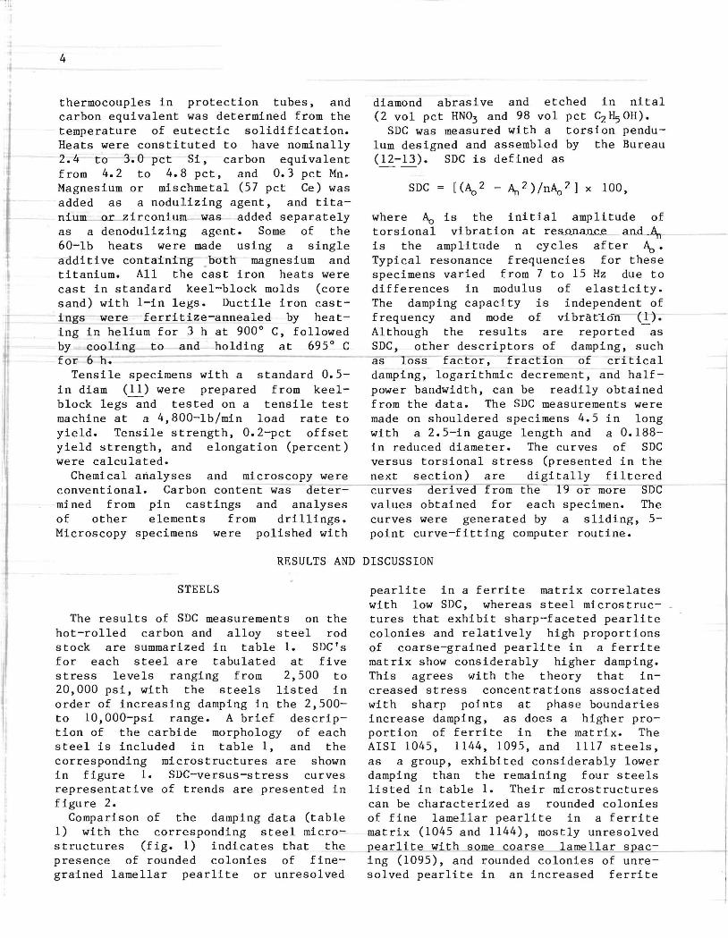
The results of SDC measurements on the hot-rolled carbon and alloy steel rod stock are summarized in table 1. SDC's for each steel are tabulated at five stress levels ranging from 2,500 to 20,000 psi, with the steels listed in order of increasing damping in the 2,500-to 10,000-psi range. A brief description of the carbide morphology of each steel is included in table 1, and the corresponding microstructures are shown in figure 1. SDC-versus-stress curves representative of trends are presented in figure 2.
Comparison of the damping data (table 1) with the corresponding steel microstructures (fig. 1) indicates that the presence of rounded colonies of finegrained lamellar pearlite or unresolved
pearlite in a ferrite matrix correlates with low SDC, whereas steel microstructures that exhibit sharp-faceted pearlite colonies and relatively high proportions of coarse-grained pearlite in a ferrite matrix show considerably higher damping. This agrees with the theory that increased stress concentrations associated with sharp points at phase boundaries increase damping, as does a higher proportion of ferrite in the matrix. The AISI 1045, 1144, 1095, and 1117 steels, as a group, exhibited considerably lower damping than the remaining four steels listed in table 1. Their microstructures can be characterized as rounded colonies of fine lamellar pearlite in a ferrite matrix (1045 and 1144), mostly unresolved pearlite with some coarse lamellar spacing (1095), and rounded colonies of unresolved pearlite in an increased ferrite
5
FIGURE 1.-Mlcrostructures of carbon and alloy steels (X 500). AISI designations: A, 1045; B, 1144; C, 1095; D, 1117.
6
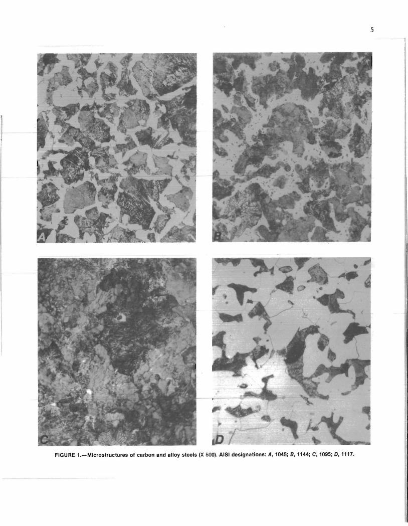
FIGURE 1.- Mlcrostructures of carbon and alloy steels (X 500)-Continued. AISI designations: E, 4140; F, 4340; G, 1035; H, 1020.

7
TABLE 1. ~ Specific damping capacities and microstructures of carbon and alloy steels
Steel, Specific damping caJacity, pct Microstructure AISll 2,500 psi 5,000 psi 10,000 psi 15,000 psi 20,000 psi 1045 •• 0.2 0.2 0.3
1144 •• .3 .4 .6 1095 •• .3 .5 .7
1117 •• .6 .9 1.1
4140 •• .3 .8 1.6 --
4340 •• • 5 1.1 1.9 1035 •• .7 1.1 1.9
1020 •• 1.5 2.0 2. 1
lMicrostructures are shown in figure 1.
matrix (1117). Damping for the AISI 4140, 4340, 1035, and 1020 steels was higher. They were characterized by lamellar pearlite colonies with fine-tocoarse spacing in ferrite (4140 and 4340), coarse grained structure of sharpfaceted pearlite in a matrix of ferrite (1035), and reduced quantities of
10 I I I I -u / 0-
j . >- 8 I- KEY / -I-
U " .• •• •• . AISI 1020 / <l --AISI 1045 n. - --- AIS I 1095 / <l
- . _ . _ . AIS I 4140 / U 6 r- -
/ <.:> j ~ n. 4 - j -~
/ <l 0 /
/ u 2 - .. ·········· · ·· .. 7 ····· ·· ···· -LL
---U . ---w
--- - - -- ---n. -(j) I
0 5,000 10 ,000 15 ,000 2 0 ,000 25,000
STR ESS, p s i
FIGURE 2.-Specific damping capacity of carbon and alloy steels as a function of stress.
0.4 0.5 Rounded colonies of fine lamellar pearlite in ferri te matrix.
.8 .9 Do.
.9 1.5 Mostly unresolved pearl-ite with some lamellar spacing.
1.0 1.0 Rounded colonies of unre-solved pearlite in pre-dominant ferrite.
3.9 8.4 Fine-to-coarse lamellar pearli te in ferrite matrix.
2.9 5.3 Do • 2.9 8.1 Sharp-faceted colonies of
2. 1
fine lamellar pearlite in ferrite matrix.
2.9 Limi ted pearlite in large, sharp-faceted grains of ferrite.
sharp-faceted pearlite in ferrite matrix (l020).
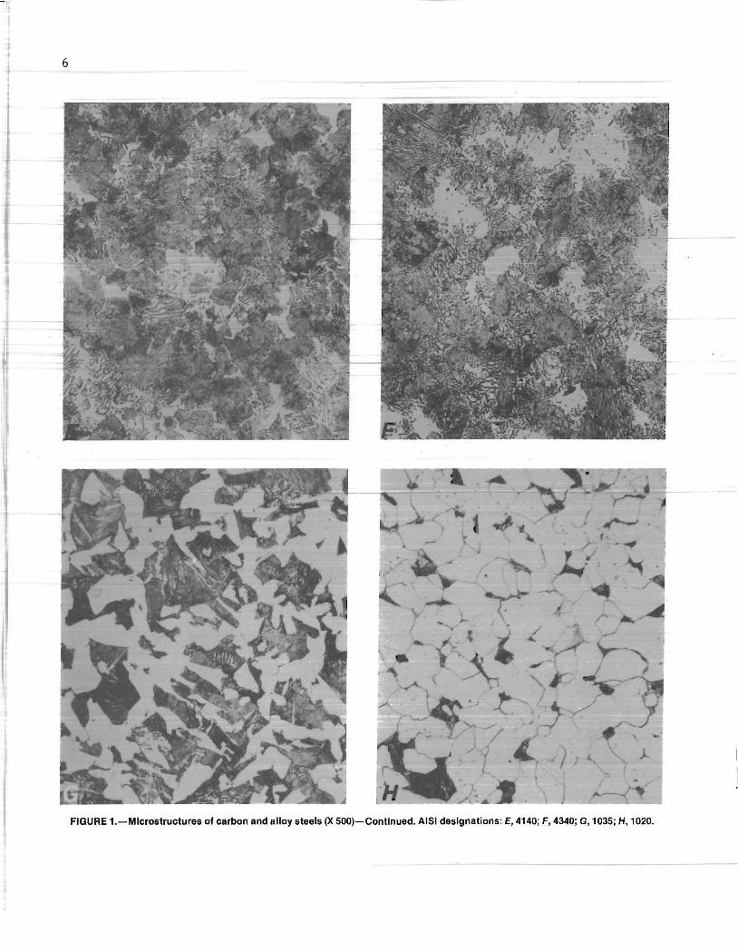
The damping capacities of three of five specimens were improved by carburizing and spheroidizing heat treatment, which altered the carbide morphology. Table 2 summarizes the SDC's of the five specimens, and figure 3 shows their corresponding ca rbide morphologies. It is evident from the photomicrographs in figure 3 that, in all cases, the lamellar pearlite was converted to partly spheroidized pearlite and spheroidal cementite.
SDC's for all carbon steels (1045, 1095, and 1144) improved, especially at stress levels above 10,000 psi. All of these steels had rather low initial SDC's, and spheroidizing improved the SDC by a factor of 2 at the 5,000-psi stress level and by as much as tenfold at the 20,000-psi stress level. The SDC of the 4140 alloy steel did not change, but this ma terial exhibited high damping prior to the heat treatment. The SDC of the 4340 alloy steel decreased somewhat in the 10,000- to 20,000-psi stress range, although this alloy also s howed good
I Ii
8
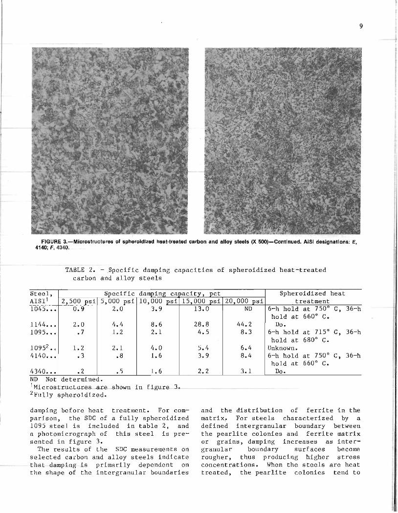
FIGURE 3.-Mlcrostructures of spheroidized heat·treated carbon and alloy steels (X 500). AISI designations: A, 1045; S, 1144; C, 1095; D, 1095 (fully spheroldlzed).
9
FIGURE 3.-Microstructuresol spheroldlzed heat·treated carbon and alloy steels (X 500)-Continued. AISI designations: E, 4140; F, 4340:
TABLE 2. - Specific damping capacities of spheroidized heat-treated carbon and alloy steels
Steel, Specific damping ca)acity, pct Spheroidized heat AISll 2,500 psi 5,000 psi 10,000 psi 15,000 psi 20,000 psi treatment 1045 ••• 0.9 2.0 3.9
1144 ••• 2.0 4.4 8.6 1095 ••• .7 1.2 2. 1
10952 .0 1.2 2.1 4.0 4140 ••• .3 .8 1.6
4340 ••• .2 .5 1.6 ND Not determined. 1 Microstrucuu:es _aLe shown in figure 3 . 2Fully spheroidized.
damping before heat treatment. For comparison, the SDC of a fully spheroidized 1095 steel is included in table 2, and a photomicrograph of this steel is presented in figure 3.
The results of the SDC measurements on selected caLbon and alloy steels indicate that damping is primarily dependent on the shape of the intergranular boundaries
13.0 ND 6-h hold at 750 0 C, 36-h hold at 660 0 C.
28.8 44.2 Do. 4.5 8.3 6-h hold at 715 0 C, 36-'-h
hold at 680 0 C. 5.4 6.4 Unknown. 3.9 8.4 6-h hold at 750 0 C, 36-h
hold at 660 0 C. 2.2 3.1 Do.
and the distribution of ferrite in the matrix~ For steels characterized by a defined intergranular boundary between the pearlite colonies and ferrite matrix or grains, damping increases as intergranular boundary surfaces become rougher, thus producing higher stress concentrations. When the steels are heat treated, the pearlite colonies tend to
10
lose their identity as the lamellar carbides begin to spheroidize and the ferrite agglomerates into a more continuous form. It is surmised that as the grain boundaries disappear during spheroidization, they lose their influence on damping, and the stress concentrations associated with the phase boundaries become ~redominant. For a gi ven carbon content, more phase-boundary surface area is present for partially spheroidized carbides than for fully spheroidized carbides. Partially spheroidized particles are more sharply faceted and would tend to exhibit higher damping. As spheroidization increases, the total cementite surface area becomes smaller and smoother ; whereas t~e ferrite becomes more continuous. The decrease in surface area and i-ncreased smoothness would tend to decrease damping; whereas, increased ferrite would tend to increase damping. This was observed in the AISI 1095 steels, where the partially spheroidized steel had
higher damping at the 20,OOO-psi stress level than the fully spheroidized steel. Manipulating these parameters in steels can enhance, or also reduce, the inherent damping associated with them.
CAST IRONS
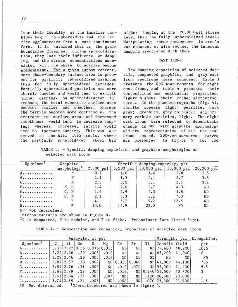
The damping capacities of selected ductile, compacted graphJ.te, and gray cast iron specimens were measure~ Table- :3 presents the SOC measurements for eight cast irons, and table 4 presents their compositions and mechanical properties. Figure 4 shows their etched microstructures. In the photomicrographs {-f-i-g.- 4), ferrite appears light; pearlite, dark gray; graphite, gray-to-black; and primary carbide particles, light. The eight cast irons were selected to demonstrate change in SDC with graphite morphology and are representative of all the cast irons tested. SDC-versus-stress curves are presented in figure 5 for two
TABLE 3. - Specific damping capacities and graphite morphologies of selected cast irons
Specimen' Graphite Specific damping capacity, pct morphology2 2,500 psi 5,000 psi 10,000 psi 15,000 psi 20,000 psi
A ••••••••••••• N 0.7 1.0 1.6 2.0 2.5 B ••••••••••••• N 1.1 1.5 2. 1 2.7 3.3 c .•••....•.••• N 2.3 3.0 3.1 3. 1 3.2 D .............. N, C 1.4 2.0 2.7 4.3 ND E ••••••••••••• C, N 1.9 2.9 4.3 5.8 ND F ••••••••••••• C, N 2. 1 3.3 5.2 7.0 ND G ••••••••••••• F 4.1 5.7 9.2 12.5 ND H ••••••••••••• F 13.0 15.9 22.0 ND ND ND Not determined. 'Microstructures are shown in figure 4. 2C is compacted, N is nodular, and F is flake. Predominant form listed first .
TABLE 4. - Composition and mechanical properties of selected cast irons
Analysis, wt ct Strength, psi Elongation, Specimen 1 C Si Mn S Mg Ce Zr Ti Tensile Yield pct
A ••••••••••• 3.55 2.22 0.55 0.016 0.035 ND ND ND 79,600 48,200 10.5 B • • ••••••••• 3.22 2.46 .29 .005 .016 ND ND ND 65,200 41,900 18 c ••••••••••• 3.22 2,46 .29 .005 .016 ND ND ND ND ND ND D ••••••••••• 3.84 2.37 .30 .002 ND 0.015 0.060 ND 61,900 44,100 7.5 E ••••••••••• 3.84 2.76 .31 .002 ND .012 .070 ND 55,300 41,900 5.5 F • ••• •••• • • • 3.82 2.79 .29 . 004 ND . 014 ND 0 . 240 51,600 40,700 3 G ••••••••••• 3.61 2.64 .24 .005 .007 ND ND .120 26,600 23,800 1 H ••••••••••• 3.74 2.68 .29 .007 ND .008 ND .070 25,300 21, 900 1.5 ND Not determined. I Microstructures are shown 1n figure 4.
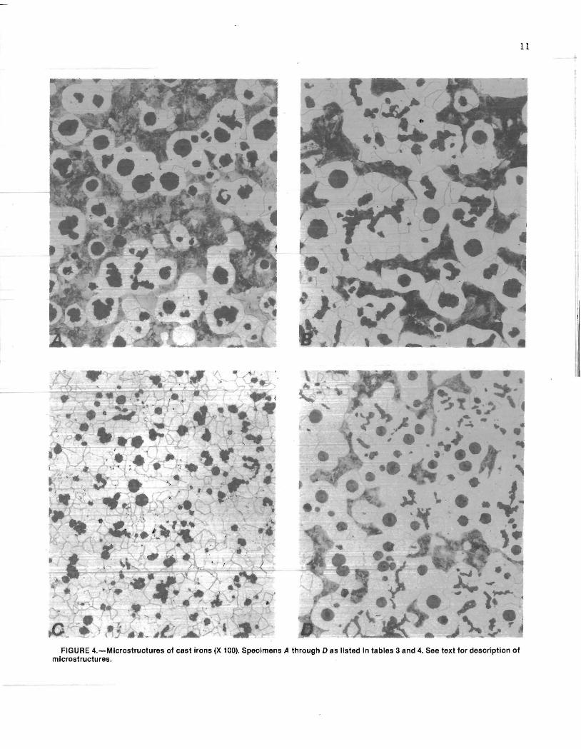
FIGURE 4.-Microstructures of cast irons (X 100). Specimens A through D as listed In tables 3 and 4. See text for description of microstructures.
11
12
FIGURE 4.-Microstructures of cast Irons (X 100)-Continued. Specimens E through H as listed in tables 3 and 4. See text for description of microstructures.
20 ,-------y----:---.---,--------y---
18
..... u 16 a.
>- 14 r-U <t a.. 12 <t U
~ 6 LL
U w a.. 4 (f)
2
o
KEY Ductile cost iron A
- - - - - Ductile cost iron C -. - . _ . --.. Compacted graphite
cast iron F ..•••...••••• Gray cost iron G
/ ./
/' /
5,000 10,000 15,000 20,000 25,000
STRESS, psi
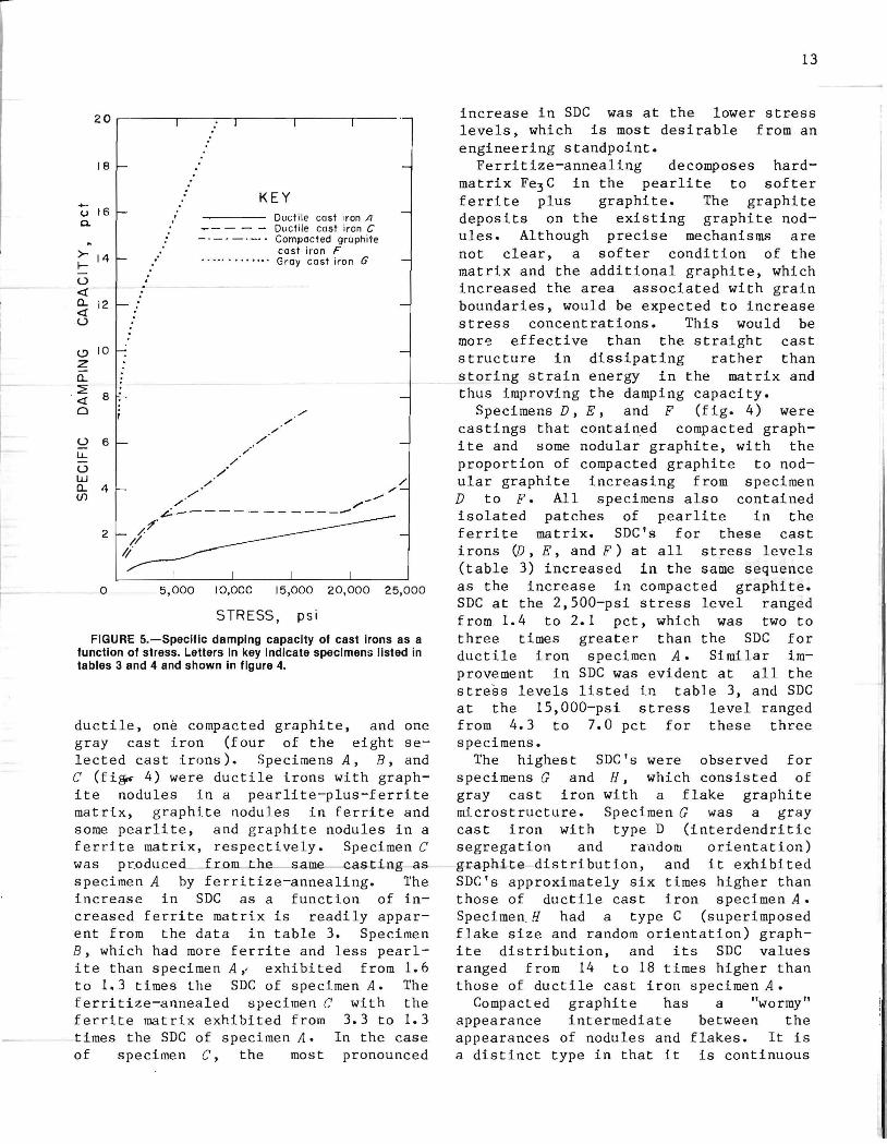
FIGURE 5.-Specific damping capacity of cast irons as a function of stress. Letters in key indicate specimens listed in tables 3 and 4 and shown in figure 4.
ductile, one compacted graphite, and one gray cast iron (four of the eight selected cast irons). Specimens A, B, and C (fi~ 4) were ductile irons with graphite nodules in a pearlite-pIus-ferrite matrix, graphite nodules in ferrite and some pearlite, and graphite nodules in a ferrite matrix, respectively. Specimen C was produced from the s.arne casting as specimen A by ferritize-annealing. The increase in SDC as a function of increased ferrite matrix is readily apparent from the data in table 3. Specimen B, which had more ferrite and less pearlite than specimen A" exhibited from 1.6 to 1.3 times the SDC of specimen A. The ferritize-annealed specimen C with the ferrite matrix exhibited from 3.3 to 1.3 times the SDC of specimen A. In the case of specimen C, the most pronounced
13
increase in SDC was at the lower stress levels, which is most desirable from an engineering standpoint.
Ferritize-annealing decomposes hardmatrix Fe3C in the pearlite to softer ferrite plus graphite. The graphite deposits on the existing graphite nodules. Although precise mechanisms are not clear, a softer condition of the matrix and the additional graphite, which increased the area associated with grain boundaries, would be expected to increase stress concentrations. This would be mor~ effective than the straight cast structure in dissipating rather than storing strain energy in the matrix and thus improving the damping capacity.
Specimens D, E, and F (f ig. 4) were castings that contained compacted graphite and some nodular graphite, with the proportion of compacted graphite to nodular graphite increasing from specimen D to F. All specimens also contained isolated patches of pearlite in the ferrite matrix. SDC's for these cast irons (j), E, andF) at all stress levels (table 3) increased in the same sequence as the increase in compacted graphite. SDC at the 2,SOO-psi stress level ranged from 1.4 to 2.1 pct, which was two to three times greater than the SDC for ductile iron specimen A. Similar im~
provement in SDC was evident at all the stress levels listed in table 3, and SDC at the IS,OOO-psi stress level ranged from 4.3 to 7.0 pct for these three specimens.
The highest SDC's were observed for specimens G and H, which consisted of gray cast iron with a flake graphite microstructure. Specimen G was a gray cast iron with type D (interdendritic segregation and random orientation) ~raphite distribution, and it exhibited SDC's approximately six times higher than those of ductile cast iron specimen A • SpecimenH had a type C (superimposed flake size and random orientation) graphite distribution, and its SDC values ranged from 14 to 18 times higher than those of ductile cast iron specimen A.
Compacted graphite has a "wormy" appearance intermediate between the appearances of nodules and flakes. It is a distinct type in that it is continuous
I 14
in the bulk matrix, as are the flakes of gray cast iron; but, compared with the sharp edges of flakes, the rounded edges are less effective for stress concentration and resultant vibration energy dissipation. For a given matrix, these rounded edges account, to a large extent for the SDC of compacted graphite cast iron falling between those of ductile and gray c-a-st- i r on.
Comparison of the cast iron damping capacities in table 3 with the mechanical properties in table 4 indicates an
inverse relationship between SDC and elongation and tensile and yield strength. SDC increases as percent elongation and tensile and yield strength decrease. This is not unexpected, because the trend follows the sequence of graphite mo r phology from nodular to compacted to flake or their various combinations. Thus, in the absence of SDC data for cast irons, elongation and tensile and yield strength information can - be U-8-€!·d--t-G-~a-r:
rive at an estimate of their damping capabilities.
CONCLUSIONS
The steels and cast irons investigated boundaries and the presence of ferrite here represent only a small fraction of in the matrix. Damping improves with the carbide and graphite morphologies rougher intergranular contact, increased possible for these materials. The intent ferrite, or their various combinations. of the study was to provide baseline Heat treatments that accentuate these damping capacity data for some common conditions · in the matrix increase dampstructural and engineering materials, and ing. Compared to carbon and alloy to determine relationships between damp- steels, cast irons even with the lowest ing capacity and material microstructure. SDC's exhibit better damping in most The results indicate that damping in cases. The SDC of some alloy steels can both the steels and cast irons examined be increased to the level of cast iron is strongly dependent on th~ leve~ of ____ S_D_C~'s~b~y~. h~e~a_t~t~r~e_a~t_i_n~g~. ________ __ stress associated with the intergranular
REFERENCES
1. Jensen, J. W., and Q. F. Walsh. Manganese-Copper Damping Alloys. BuMines B 624, 1965, 55 pp.
2. Holman, J. L., R. L. Crosby, and L. A. Neumeier. Properties of Manganese-Copper Alloys Prepared From Metal Powders. BuMines RI 8383, 1979, 32 pp.
3. Birchon, D. Hidamets--Metals to Reduce Noise and Vibration. Min. Eng. (London), v. 222, Aug. 1966, pp. 207-209.
4. Fister, J. C., and J. F. Breedis. Improved High Damping Copper-Base Alloys. Int. Copper Res. Assoc., New York, NY. INCRA Final Rep. 221, Jan. 1976, 32 pp.
5. Nachman, J. F., and A. N. Hammer. Characteristics of Commercial Incramute 1. Int. Copper Res. Assoc., New York, NY. INCRA Rep. RDR 1713, Nov. 1971, 12 pp.
6. Nachman, J. F., C. Napier, and A. N. Hammer. Development of Cu-Mn Base
Alloys With High Damping Properties. Int. Copper Res. Assoc., New York, NY. INCRA Final Rep. 152-152A, March 1971, 23 pp.
7. Toshiba Research and Development Center. Silentalloy SIA Technical Data. Tokyo Shibaura Electric Co., Ltd., Kamukai, Kawasaki, Japan, 13 pp.
8. Clarke, H. Effect of Pore Geometry on the Damping Characteristics of Sintered Irons. Paper in Modern Developments in Powder Metallurgy, v. 11, P/M Special Materials and Applications, ed. by H. H. Hausher and P. V. Taubenblat (Proc. 1976 Int. Powder Met. Conf., Chicago, IL, June 27-July 2, 1976). Metal Powder Ind. Fed., Princeton, NJ, pp. 385-395.
9. Cowen, P. S. Part 1: Heat Treatment of Ductile Iron Castings. Foundry, v. 99, No.9, 1971, pp. 60-63.
10. Cowen, P. S. Part 2: Heat Treatment of Ductile Iron Castings. Foundry, v. 99, No. 10, 1971, pp. 78-81.
11. American Society for Testing and Materials. Standard Method and Definitions for Mechanical Testing of Steel Products. ANSljASTM A370-77 in 1981 Annual Book of ASTM Standards: Part 2, Ferrous Castings; Ferroalloys. Philadelphia, PA, 1981, pp. 187,..242.
U.S. GOVERNMENT PRINTING OFFICE: 1987 · 605·017 /60011
15
12. Schwaneke, A. E., and R. W. Nash. An Improved Torsion Pendulum for Measuring Internal Damping. Rev. Sci. Instrum., v. 40, 1969, pp. 1450-1453.
13. Nash, R. W., and A. E. Schwaneke. A Digital Instrumentation Package for an Improved Torsion Pendulum. BuMines RI 8774, 1983, 9 pp.
INT.-BU.OF MINES,PGH.,PA. 28400