a design study in ductile iron pivot plate frame for the ... · afs home page copyright 2005 by ......
TRANSCRIPT

Title Page -- Ductile Iron Casting
A Design Study in Ductile Iron
Pivot Plate Frame for the Pouring Chute on a Cement Mixer Truck
Design Study OutlineIntroductionDesign for Performance Ductile Iron Alloy Grade Selection Finite Element Analysis Design for Production Molding Method Directional Solidification Core DesignFinal Design and Pouring Quality AssuranceLessons Learned and Summary
Key Words = metal casting, ductile iron, Dotson Company, green sand, A536 Start the Design Study !
Acknowledgment -- The metalcasting design studies are a joint effort of the
American Foundry Society and the Steel Founders' Society of America.Project funding was provided by the American Metalcasting Consortium Project, which
is sponsored by the Defense Logistics Agency, Attn: DLSC-T, Ft. Belvoir, VA, 22060-6221
AFS Home Page
Copyright 2005 by the American Foundry Society. All rights reserved. Address Comments to: [email protected] Modified:September, 2005 by STG
In cooperation withThe Dotson Company.
file:///C|/A-My%20Documents/My%20Webs/DotsonPlate/index.htm [9/15/05 9:34:30 PM]

Application
A Design Study in Ductile Iron - Dotson Company Pivot Frame
Pivot Plate Frame -- ApplicationThe McNeilus Company (a subsidiary of Oshkosh Truck) has been
producing concrete mixer trucks for the heavy construction industry since 1975.
● The mixer trucks carry, deliver, mix, and pour concrete on-site and come in a range of load capacities (4 to 15 cubic yards of concrete. A cubic yard of concrete weighs 4000 pounds).
● The mixer trucks have to reliably deliver concrete across all kinds of terrain and weather.
● Each component of the truck has to be rugged and durable to withstand mixing and pouring stresses as well as road shock and vibration over the life of the truck. Pouring Chute on the Back of the Concrete
Mixer Truck
The metal pour chute on the rear of the truck carries the concrete mix from the drum down to the concrete forms. The chute is designed to swing across a 160° arc so that concrete is easily poured into forms without having to reposition the truck.
Back Next 2
AFS Home Page
Copyright 2005 by the American Foundry Society. All rights reserved. Address Comments to: [email protected]. Last Modified:September, 2005 by STG Page 1
In cooperation withThe Dotson Company.
file:///C|/A-My%20Documents/My%20Webs/DotsonPlate/Plate_02.htm [9/15/05 9:34:35 PM]

Function
A Design Study in Ductile Iron - Dotson Company Pivot Frame
Pivot Plate Frame -- Function
The original welded pivot frame assembly with the pivot shaft
attached.
The pivot plate frame installed on the truck.
An integral part of the pour chute is the pivot plate frame which supports the pouring chute, serves as a pivot point, and locks in position during the pour.
In the old truck design, the pivot plate frame structure was a nine piece steel weldment.
● The Dotson Company proposed a conversion to a casting that would reduce production costs with no penalty in weight, performance, or durability.
Back Next 3
AFS Home Page
Copyright 2005 by the American Foundry Society. All rights reserved. Address Comments to: [email protected]. Last Modified:July, 2005 by STG Page 1
In cooperation withThe Dotson Company.
file:///C|/A-My%20Documents/My%20Webs/DotsonPlate/Plate_03.htm [9/15/05 9:34:43 PM]

Description
A Design Study in Ductile Iron - Dotson Company Pivot Frame
Pivot Plate Frame -- DescriptionThe newly designed pivot plate frame casting has a weight of 40# and
consists of a central hub, a flat locking plate, a square mounting frame, and a rib-stiffened triangular support frame.
● The envelope dimensions of the pivot frame casting are 19" x 14" x 6".
● The center hub has a diameter of 3" inches and a height of 3.5".
● The minimum wall thickness is 0.375".
● The center hub of the plate frame secures the pivot shaft on which the plate and chute rotate.
● The locking plate has seven lock holes for securing the chute at different swing angles. ● The two bushings on the top of the triangular frame secure pouring chute to the pivot
frame.
Back Next 4
AFS Home Page
Copyright 2005 by the American Foundry Society. All rights reserved. Address Comments to: [email protected]. Last Modified:September, 2005 by STG Page 1
In cooperation withThe Dotson Company.
file:///C|/A-My%20Documents/My%20Webs/DotsonPlate/Plate_04.htm [9/15/05 9:34:47 PM]

Requirements
A Design Study in Ductile Iron - Dotson Company Pivot Frame
Pivot Frame -- PerformanceThe critical performance and production requirements for the plate frame are:
● Meet or exceed the strength and durability of the original weldment.
● Choose an alloy grade for sufficient toughness and ductility for fatigue and impact resistance.
● Design the casting with the selected alloy grade to keep stresses below the maximum design stress.
● Minimize machining steps and costs.● Critical dimensional features are --
❍ the machined center hole in the hub, ❍ machined mounting holes in the triangular frame, ❍ as-cast locking holes on the locking plate.
● General tolerances = 30 mils. As-cast hole tolerances are 20 mils. Machined tolerances are 5 mils.
● The surface finish requirement is "clean and smooth" with no visible surface defects or grinding marks
Locking Plate and Hub View(As-Cast before Machining)
Back Next 5
AFS Home Page
Copyright 2005 by the American Foundry Society. All rights reserved. Address Comments to: [email protected]. Last Modified:July, 2005 by STG Page 1
In cooperation withThe Dotson Company.
file:///C|/A-My%20Documents/My%20Webs/DotsonPlate/Plate_05.htm [9/15/05 9:34:52 PM]
Conversion
A Design Study in Ductile Iron - Dotson Company Pivot Frame
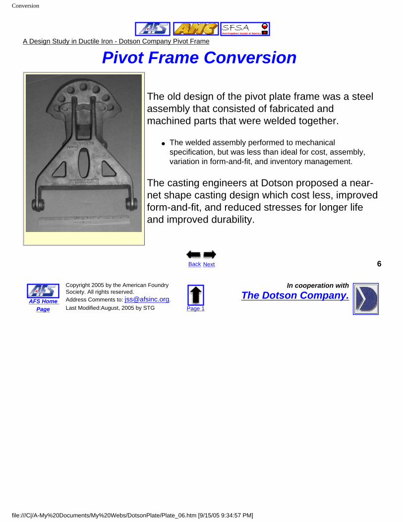
Pivot Frame Conversion
The old design of the pivot plate frame was a steel assembly that consisted of fabricated and machined parts that were welded together.
● The welded assembly performed to mechanical specification, but was less than ideal for cost, assembly, variation in form-and-fit, and inventory management.
The casting engineers at Dotson proposed a near-net shape casting design which cost less, improved form-and-fit, and reduced stresses for longer life and improved durability.
Back Next 6
AFS Home Page
Copyright 2005 by the American Foundry Society. All rights reserved. Address Comments to: [email protected]. Last Modified:August, 2005 by STG Page 1
In cooperation withThe Dotson Company.
file:///C|/A-My%20Documents/My%20Webs/DotsonPlate/Plate_06.htm [9/15/05 9:34:57 PM]

Ductile Iron
A Design Study in Ductile Iron - Dotson Company Pivot Frame
Metal Alloy SelectionThe original assembly was welded from steel plates and bar stock.
But ductile cast iron is the metal of choice for this casting.
Relationship between Strength, Ductility, and Hardness for Ductile Cast Irons
Ductile iron meets the performance requirements with lower casting production cost, compared to casting a steel alloy.
● The term "cast iron" designates an entire family of metals with a wide variety of properties. Cast iron contains more than 2% carbon, present as a distinct graphite phase.
● In ductile cast iron the graphite occurs as spheroids or spherulites rather than as individual flakes as in gray iron.
● Ductile iron exhibits a linear stress-strain relation, a considerable range of yield strengths, and, as its name implies, ductility.
Back Next 7
AFS Home Page
Copyright 2005 by the American Foundry Society. All rights reserved. Address Comments to: [email protected]. Last Modified:July, 2005 by STG Page 1
In cooperation withThe Dotson Company.
file:///C|/A-My%20Documents/My%20Webs/DotsonPlate/Plate_07.htm [9/15/05 9:35:01 PM]
Ductile Iron Benefits
A Design Study in Ductile Iron - Dotson Company Pivot Frame
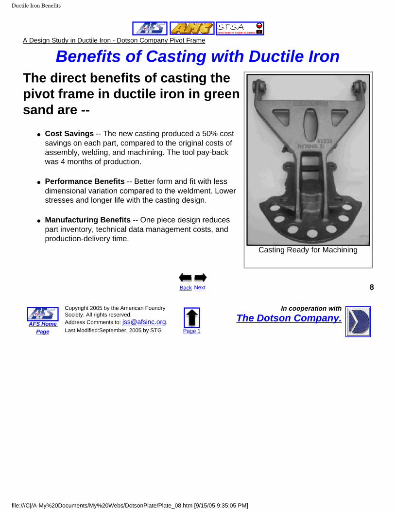
Benefits of Casting with Ductile IronThe direct benefits of casting the pivot frame in ductile iron in green sand are --
● Cost Savings -- The new casting produced a 50% cost savings on each part, compared to the original costs of assembly, welding, and machining. The tool pay-back was 4 months of production.
● Performance Benefits -- Better form and fit with less dimensional variation compared to the weldment. Lower stresses and longer life with the casting design.
● Manufacturing Benefits -- One piece design reduces part inventory, technical data management costs, and production-delivery time.
Casting Ready for Machining
Back Next 8
AFS Home Page
Copyright 2005 by the American Foundry Society. All rights reserved. Address Comments to: [email protected]. Last Modified:September, 2005 by STG Page 1
In cooperation withThe Dotson Company.
file:///C|/A-My%20Documents/My%20Webs/DotsonPlate/Plate_08.htm [9/15/05 9:35:05 PM]
Design Issues
A Design Study in Ductile Iron - Dotson Company Pivot Frame
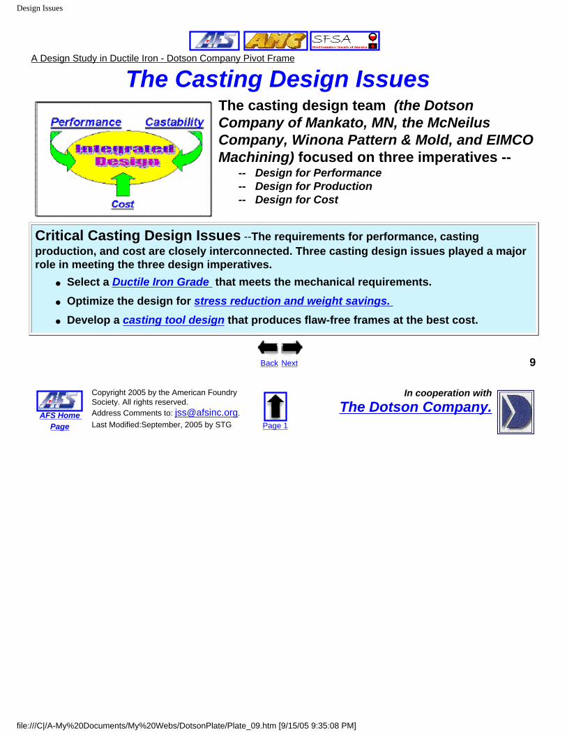
The Casting Design Issues The casting design team (the Dotson Company of Mankato, MN, the McNeilus Company, Winona Pattern & Mold, and EIMCO Machining) focused on three imperatives --
-- Design for Performance-- Design for Production-- Design for Cost
Critical Casting Design Issues --The requirements for performance, casting production, and cost are closely interconnected. Three casting design issues played a major role in meeting the three design imperatives.
● Select a Ductile Iron Grade that meets the mechanical requirements.● Optimize the design for stress reduction and weight savings. ● Develop a casting tool design that produces flaw-free frames at the best cost.
Back Next 9
AFS Home Page
Copyright 2005 by the American Foundry Society. All rights reserved. Address Comments to: [email protected]. Last Modified:September, 2005 by STG Page 1
In cooperation withThe Dotson Company.
file:///C|/A-My%20Documents/My%20Webs/DotsonPlate/Plate_09.htm [9/15/05 9:35:08 PM]

A-536 Selection
A Design Study in Ductile Iron - Dotson Company Pivot Frame
Ductile Iron Grade SelectionThe ductile iron casting specifications are given in ASTM A536.
The alloy is available in five different grades. The three grades of interest are shown below, along with the performance requirements.
ASTM A536 Grades PerformanceRequirement
ChooseA536 Grade 2
65-45-12
ChooseA536 Grade 3
80-55-06
ChooseA536 Grade 4
100-70-03 Ultimate Tensile Strength >80 ksi 65 ksi min 80 ksi min 100 ksi min Yield Strength >55 ksi 45 ksi min 55 ksi min 70 ksi min % Elongation >6% 12% min 6% min 3% min Hardness >195 BHN 156-217 BHN 187-255 BHN 241-302 BHN
Given the mechanical property requirements for the pivot plate, consider the nominal properties of the three A536 grades in the table above.
Choose the grade that best meets the mechanical requirements.
Back
Choose an alloy grade above 10
AFS Home Page
Copyright 2005 by the American Foundry Society. All rights reserved. Address Comments to: [email protected]. Last Modified:July, 2005 by STG Page 1
In cooperation withThe Dotson Company.
file:///C|/A-My%20Documents/My%20Webs/DotsonPlate/Plate_10.htm [9/15/05 9:35:12 PM]

A-536 Grade 3
A Design Study in Ductile Iron - Dotson Company Pivot Frame
A536 Grade 2The ASTM A536 ductile iron casting specification is based on demonstrated mechanical
properties which depend on the proper cast iron microstructure.
The difference between the various grades of ductile iron is in the microstructure of the metal around the graphite.
This microstructure varies with the composition (relative amounts of carbon, silicon, nickel, manganese, etc) and the cooling rates in the casting.
● High ductility grades have a ferrite microstructure.
● Intermediate grades have a mixed ferrite and pearlite microstructure.
● High strength grades have a primary pearlite microstructure.
The Grade 2 casting with a primary ferrite microstructure has more than sufficient ductility/elongation and just misses the hardness requirement, but it doesn't meet the
minimum requirements for ultimate tensile strength and yield strength. The Grade 2 is not the best choice.
Go Back for Another Choice!
Back 11
AFS Home Page
Copyright 2005 by the American Foundry Society. All rights reserved. Address Comments to: [email protected]. Last Modified:September, 2005 by STG Page 1
In cooperation withThe Dotson Company.
file:///C|/A-My%20Documents/My%20Webs/DotsonPlate/Plate_10a.htm [9/15/05 9:35:18 PM]

A-536 Grade 3
A Design Study in Ductile Iron - Dotson Company Pivot Frame
A536 Grade 3The ASTM A536 ductile iron casting specification is based on demonstrated mechanical
properties which depend on the proper cast iron microstructure.
The difference between the various grades of ductile iron is in the microstructure of the metal around the graphite.
This microstructure varies with the composition (relative amounts of carbon, silicon, nickel, manganese, etc) and the cooling rates in the casting.
● High ductility grades have a ferrite microstructure.
● Intermediate grades have a mixed ferrite and pearlite microstructure.
● High strength grades have a primary pearlite microstructure.
The Grade 3 casting with a mixed ferrite/pearlite microstructure meets all the mechanical requirements for ultimate tensile strength, yield strength, ductility/elongation, and hardness.
The Grade 3 is the best choice.Go to the Next Design Issue
Back Next 12
AFS Home Page
Copyright 2005 by the American Foundry Society. All rights reserved. Address Comments to: [email protected]. Last Modified:September, 2005 by STG Page 1
In cooperation withThe Dotson Company.
file:///C|/A-My%20Documents/My%20Webs/DotsonPlate/Plate_10b.htm [9/15/05 9:35:24 PM]
A-536 Grade 4
A Design Study in Ductile Iron - Dotson Company Pivot Frame
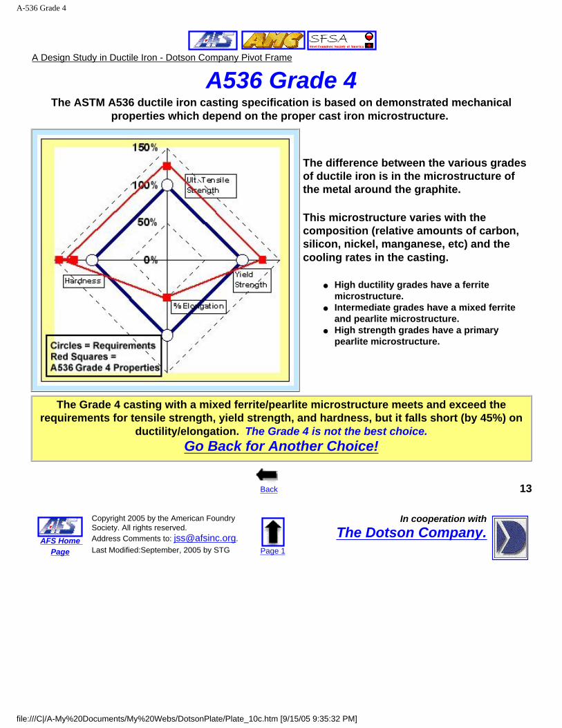
A536 Grade 4The ASTM A536 ductile iron casting specification is based on demonstrated mechanical
properties which depend on the proper cast iron microstructure.
The difference between the various grades of ductile iron is in the microstructure of the metal around the graphite.
This microstructure varies with the composition (relative amounts of carbon, silicon, nickel, manganese, etc) and the cooling rates in the casting.
● High ductility grades have a ferrite microstructure.
● Intermediate grades have a mixed ferrite and pearlite microstructure.
● High strength grades have a primary pearlite microstructure.
The Grade 4 casting with a mixed ferrite/pearlite microstructure meets and exceed the requirements for tensile strength, yield strength, and hardness, but it falls short (by 45%) on
ductility/elongation. The Grade 4 is not the best choice.Go Back for Another Choice!
Back 13
AFS Home Page
Copyright 2005 by the American Foundry Society. All rights reserved. Address Comments to: [email protected]. Last Modified:September, 2005 by STG Page 1
In cooperation withThe Dotson Company.
file:///C|/A-My%20Documents/My%20Webs/DotsonPlate/Plate_10c.htm [9/15/05 9:35:32 PM]

Stress Reduction - FEA
A Design Study in Ductile Iron - Dotson Company Pivot Frame
Finite Element AnalysisOne of the design advantages of metal casting is the freedom to optimize
cross-sections and shapes beyond the limits of welded plates and bar stock.
The collaborative design team considered how to design the triangular support frame with two objectives --
● Keeping the tensile stresses in critical sections below the calculated stresses in the original welded design.
● Minimizing the weight of the overall casting to keep production costs down and save weight on the truck.
The critical tool in this design effort was Finite Element Analysis (FEA) which was used to determine tensile stresses in different designs.
Back Next 14
AFS Home Page
Copyright 2005 by the American Foundry Society. All rights reserved. Address Comments to: [email protected]. Last Modified:September, 2005 by STG Page 1
In cooperation withThe Dotson Company.
file:///C|/A-My%20Documents/My%20Webs/DotsonPlate/Plate_11.htm [9/15/05 9:35:40 PM]
Design Iterations
A Design Study in Ductile Iron - Dotson Company Pivot Frame
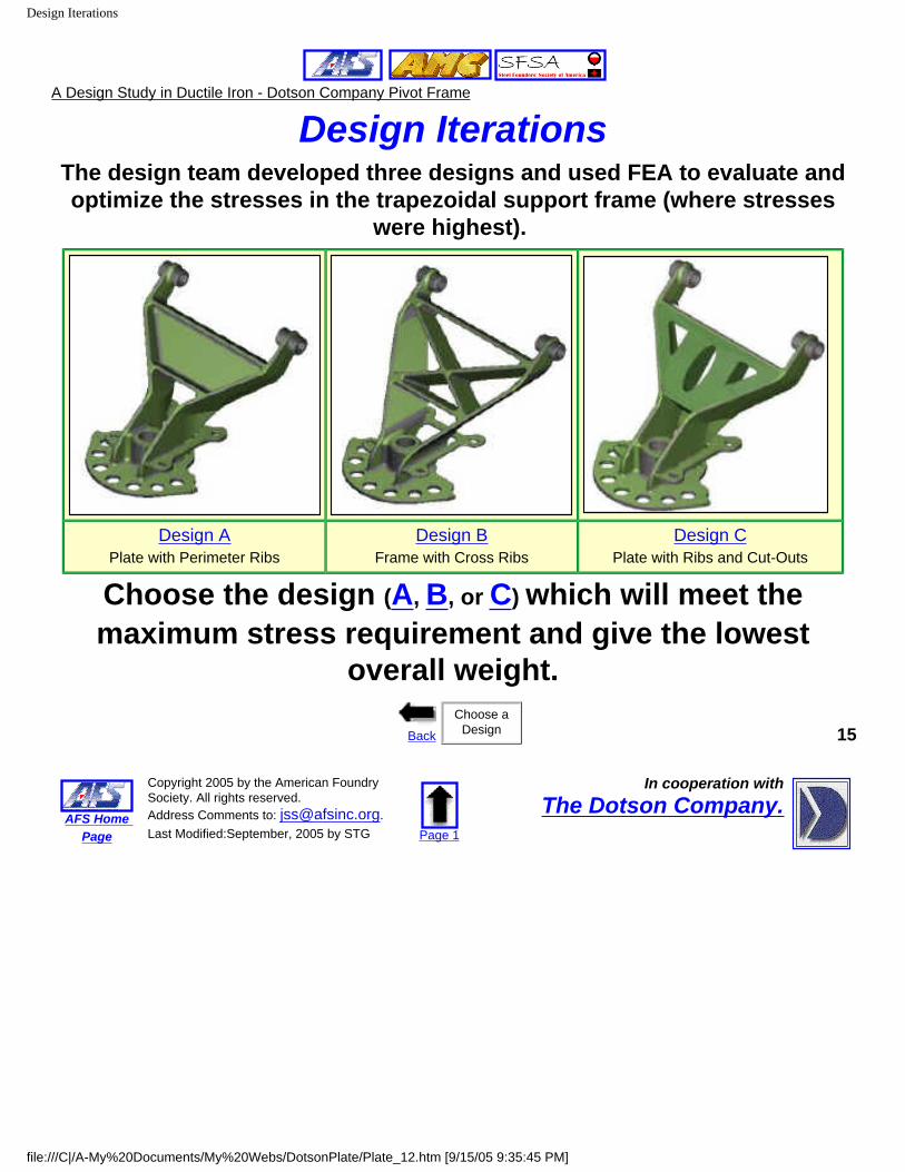
Design IterationsThe design team developed three designs and used FEA to evaluate and optimize the stresses in the trapezoidal support frame (where stresses
were highest).
Design APlate with Perimeter Ribs
Design BFrame with Cross Ribs
Design CPlate with Ribs and Cut-Outs
Choose the design (A, B, or C) which will meet the maximum stress requirement and give the lowest
overall weight.
BackChoose a
Design 15
AFS Home Page
Copyright 2005 by the American Foundry Society. All rights reserved. Address Comments to: [email protected]. Last Modified:September, 2005 by STG Page 1
In cooperation withThe Dotson Company.
file:///C|/A-My%20Documents/My%20Webs/DotsonPlate/Plate_12.htm [9/15/05 9:35:45 PM]

Design A
A Design Study in Ductile Iron - Dotson Company Pivot Frame
Design A - Plate with Perimeter Ribs
This design uses a flat plate in the support section with perimeter ribs for stiffening and stress control.
The maximum stresses were within target at the joint where the trapezoidal frame meets the straight bars, but the weight of this design was higher than desired.
Design A is not the best choice.Go Back for Another Choice!
Back 16
AFS Home Page
Copyright 2005 by the American Foundry Society. All rights reserved. Address Comments to: [email protected]. Last Modified:September, 2005 by STG Page 1
In cooperation withThe Dotson Company.
file:///C|/A-My%20Documents/My%20Webs/DotsonPlate/Plate_12a.htm [9/15/05 9:35:50 PM]
Design B
A Design Study in Ductile Iron - Dotson Company Pivot Frame
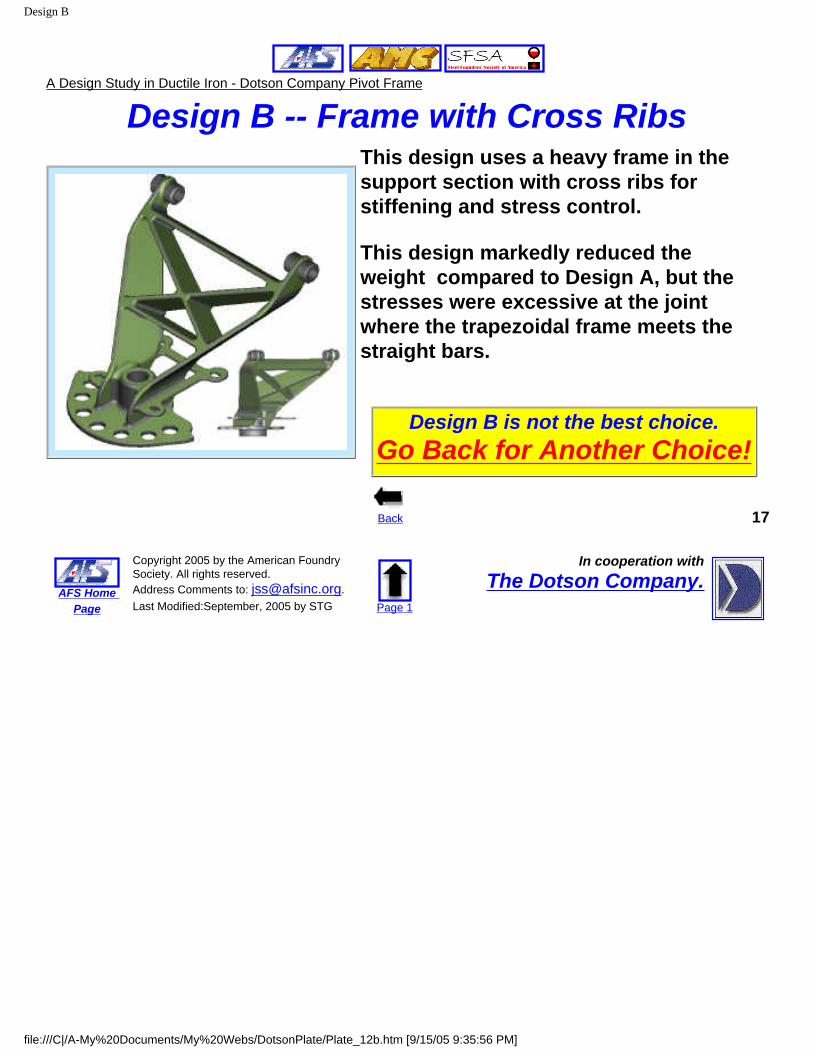
Design B -- Frame with Cross Ribs This design uses a heavy frame in the support section with cross ribs for stiffening and stress control.
This design markedly reduced the weight compared to Design A, but the stresses were excessive at the joint where the trapezoidal frame meets the straight bars.
Design B is not the best choice.Go Back for Another Choice!
Back 17
AFS Home Page
Copyright 2005 by the American Foundry Society. All rights reserved. Address Comments to: [email protected]. Last Modified:September, 2005 by STG Page 1
In cooperation withThe Dotson Company.
file:///C|/A-My%20Documents/My%20Webs/DotsonPlate/Plate_12b.htm [9/15/05 9:35:56 PM]

Design C
A Design Study in Ductile Iron - Dotson Company Pivot Frame
Design C -- Plate with Ribs and Cut-Outs
This design uses a flat plate in the support section with perimeter ribs and two long ribs in the back for stiffening.
In addition, three cut-outs in the center panel reduce the overall weight without increasing stresses in the critical sections.
This design keeps the stresses within limits at the joint where the trapezoidal frame meets the straight bars and has lower weight than Design A, meeting the weight target.
Design C is the best choice.Go on to the Next Design Issue
Back Next 18
AFS Home Page
Copyright 2005 by the American Foundry Society. All rights reserved. Address Comments to: [email protected]. Last Modified:September, 2005 by STG Page 1
In cooperation withThe Dotson Company.
file:///C|/A-My%20Documents/My%20Webs/DotsonPlate/Plate_12c.htm [9/15/05 9:36:04 PM]
Sand Molding
A Design Study in Ductile Iron - Dotson Company Pivot Frame
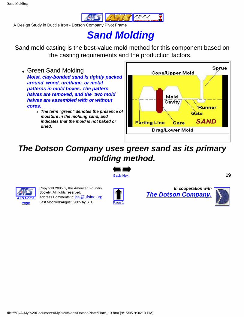
Sand Molding Sand mold casting is the best-value mold method for this component based on
the casting requirements and the production factors.
● Green Sand Molding Moist, clay-bonded sand is tightly packed around wood, urethane, or metal patterns in mold boxes. The pattern halves are removed, and the two mold halves are assembled with or without cores.
❍ The term "green" denotes the presence of moisture in the molding sand, and indicates that the mold is not baked or dried.
The Dotson Company uses green sand as its primary molding method.
Back Next 19
AFS Home Page
Copyright 2005 by the American Foundry Society. All rights reserved. Address Comments to: [email protected]. Last Modified:August, 2005 by STG Page 1
In cooperation withThe Dotson Company.
file:///C|/A-My%20Documents/My%20Webs/DotsonPlate/Plate_13.htm [9/15/05 9:36:10 PM]
Directional Solidification
A Design Study in Ductile Iron - Dotson Company Pivot Frame
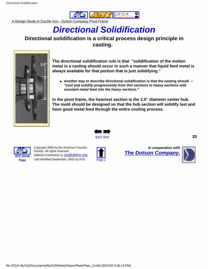
Directional SolidificationDirectional solidification is a critical process design principle in
casting.
The directional solidification rule is that "solidification of the molten metal in a casting should occur in such a manner that liquid feed metal is always available for that portion that is just solidifying."
● Another way to describe directional solidification is that the casting should -- "cool and solidify progressively from thin sections to heavy sections with constant metal feed into the heavy sections."
In the pivot frame, the heaviest section is the 2.5" diameter center hub. The mold should be designed so that the hub section will solidify last and have good metal feed through the entire cooling process.
Back Next 20
AFS Home Page
Copyright 2005 by the American Foundry Society. All rights reserved. Address Comments to: [email protected]. Last Modified:September, 2005 by STG Page 1
In cooperation withThe Dotson Company.
file:///C|/A-My%20Documents/My%20Webs/DotsonPlate/Plate_14.htm [9/15/05 9:36:14 PM]
Orientation and Riser
A Design Study in Ductile Iron - Dotson Company Pivot Frame
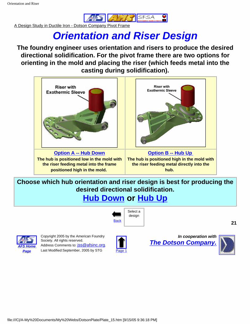
Orientation and Riser DesignThe foundry engineer uses orientation and risers to produce the desired
directional solidification. For the pivot frame there are two options for orienting in the mold and placing the riser (which feeds metal into the
casting during solidification).
Option A -- Hub DownThe hub is positioned low in the mold with
the riser feeding metal into the frame positioned high in the mold.
Option B -- Hub Up The hub is positioned high in the mold with
the riser feeding metal directly into the hub.
Choose which hub orientation and riser design is best for producing the desired directional solidification.
Hub Down or Hub Up
Back
Select a design
21
AFS Home Page
Copyright 2005 by the American Foundry Society. All rights reserved. Address Comments to: [email protected]. Last Modified:September, 2005 by STG Page 1
In cooperation withThe Dotson Company.
file:///C|/A-My%20Documents/My%20Webs/DotsonPlate/Plate_15.htm [9/15/05 9:36:18 PM]

Hub Down
A Design Study in Ductile Iron - Dotson Company Pivot Frame
Option A -- Hub Down In Option A, the heavy section hub is positioned low in the drag section of the mold in the mold and the riser (which also acts as a pouring inlet) is over the frame, which sits high in the cope section of the mold.
This design leaves the heavy hub section isolated and remote from the riser. This works against directional solidification and may produce shrinkage porosity in the hub.
The "hub down" is not a good approach for producing the desired directional solidification.
Go back and select another approach.
Back 22
AFS Home Page
Copyright 2005 by the American Foundry Society. All rights reserved. Address Comments to: [email protected]. Last Modified:September, 2005 by STG Page 1
In cooperation withThe Dotson Company.
file:///C|/A-My%20Documents/My%20Webs/DotsonPlate/Plate_15A.htm [9/15/05 9:36:26 PM]
Hub Up
A Design Study in Ductile Iron - Dotson Company Pivot Frame
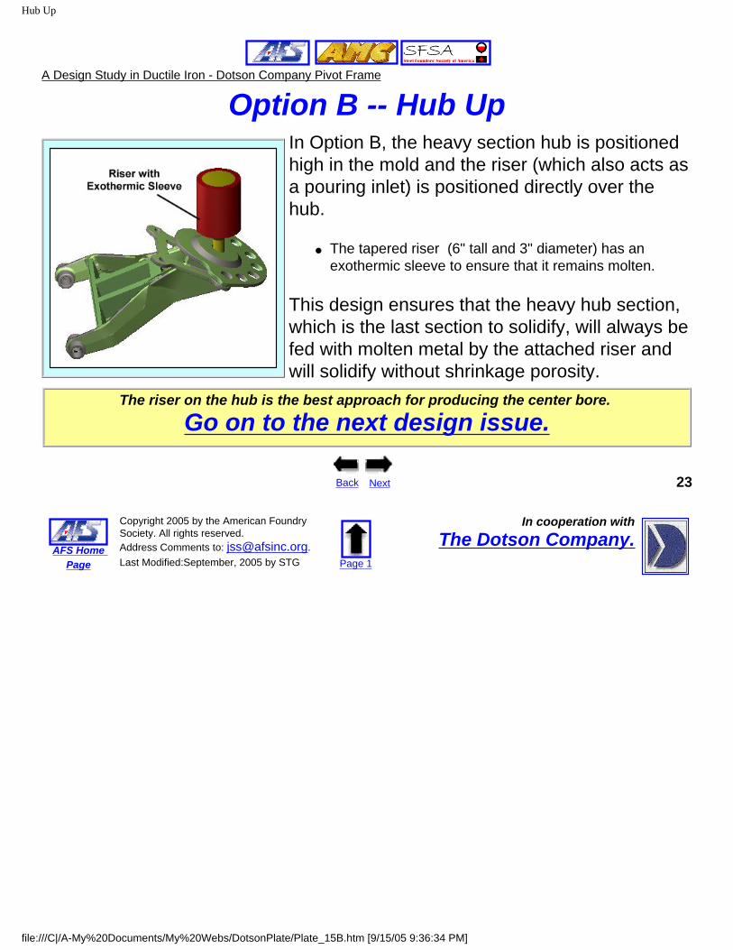
Option B -- Hub UpIn Option B, the heavy section hub is positioned high in the mold and the riser (which also acts as a pouring inlet) is positioned directly over the hub.
● The tapered riser (6" tall and 3" diameter) has an exothermic sleeve to ensure that it remains molten.
This design ensures that the heavy hub section, which is the last section to solidify, will always be fed with molten metal by the attached riser and will solidify without shrinkage porosity.
The riser on the hub is the best approach for producing the center bore.
Go on to the next design issue.
Back Next 23
AFS Home Page
Copyright 2005 by the American Foundry Society. All rights reserved. Address Comments to: [email protected]. Last Modified:September, 2005 by STG Page 1
In cooperation withThe Dotson Company.
file:///C|/A-My%20Documents/My%20Webs/DotsonPlate/Plate_15B.htm [9/15/05 9:36:34 PM]

Cores
A Design Study in Ductile Iron - Dotson Company Pivot Frame
Mold CoresCores are preformed sand shapes inserted into the mold to produce
interior and exterior features in the casting.
Red Polyurethane Core Box for Forming Two of the Center Cores
Dotson foundry engineers use six (6) cores to produce the interior features on the pivot plate frame.
● Four center cores for forming the pivot plate, center bore, and the square frame.
● Two pin cores for the center bores on the mounting bushings.
Back Next 24
AFS Home Page
Copyright 2005 by the American Foundry Society. All rights reserved. Address Comments to: [email protected]. Last Modified:September, 2005 by STG Page 1
In cooperation withThe Dotson Company.
file:///C|/A-My%20Documents/My%20Webs/DotsonPlate/Plate_16.htm [9/15/05 9:36:39 PM]

Final Mold Design
A Design Study in Ductile Iron - Dotson Company Pivot Frame
Final Mold Design
Pattern for Top Half (Cope) of the Mold Pattern for Bottom Half (Drag) of the Mold (Dotson)
● The photos above show the top and bottom halves of the pattern. ❍ The patterns are machined out of aluminum to maintain tolerances and give a long tool
life.● The top and bottom halves of the mold are formed by packing green sand
around the match plate in the metal mold boxes. ● The six cores (formed with isocure sand)are positioned in the finished
mold.● One pivot plate frame is cast in each sand mold.
Back Next 25
AFS Home Page
Copyright 2005 by the American Foundry Society. All rights reserved. Address Comments to: [email protected]. Last Modified:September, 2005 by STG Page 1
In cooperation withThe Dotson Company.
file:///C|/A-My%20Documents/My%20Webs/DotsonPlate/Plate_17.htm [9/15/05 9:36:47 PM]

Process Steps
A Design Study in Ductile Iron - Dotson Company Pivot Frame
The Production Process The plate frame is produced in a six step process.1. The molten iron (2530-2570F) is poured into the assembled sand mold and allowed to cool for 2-3 hours.
2. After cooling, the casting is removed from the sand mold by "shaking out" the sand.
3. The riser is wedged off the casting.
4. The casting is Wheelabrator shot-basted to remove residual sand on the surface.
5. Flash lines and the riser stub are ground off.
6. The casting is finished painted, prior to machining.
Automated Metal Pouring at Dotson
Back Next 26
AFS Home Page
Copyright 2005 by the American Foundry Society. All rights reserved. Address Comments to: [email protected]. Last Modified:September, 2005 by STG Page 1
In cooperation withThe Dotson Company.
file:///C|/A-My%20Documents/My%20Webs/DotsonPlate/Plate_18.htm [9/15/05 9:36:51 PM]

Machining
A Design Study in Ductile Iron - Dotson Company Pivot Frame
Machining
Three features on the pivot frame require separate machining steps.
1. The ID (2.5 inches) of the center bore is rough drilled and finish drilled to specification.
2. The ID (0.89 inches) of the two bearing holes is finish drilled to specification.
Machined Features on the Pivot Frame
Back Next 27
AFS Home Page
Copyright 2005 by the American Foundry Society. All rights reserved. Address Comments to: [email protected]. Last Modified:September, 2005 by STG Page 1
In cooperation withThe Dotson Company.
file:///C|/A-My%20Documents/My%20Webs/DotsonPlate/Plate_19.htm [9/15/05 9:36:54 PM]
Quality Assurance
A Design Study in Ductile Iron - Dotson Company Pivot Frame
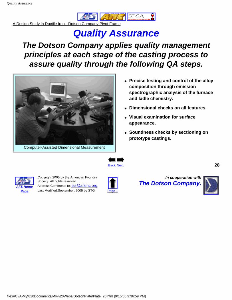
Quality AssuranceThe Dotson Company applies quality management principles at each stage of the casting process to
assure quality through the following QA steps.
Computer-Assisted Dimensional Measurement
● Precise testing and control of the alloy composition through emission spectrographic analysis of the furnace and ladle chemistry.
● Dimensional checks on all features.
● Visual examination for surface appearance.
● Soundness checks by sectioning on prototype castings.
Back Next 28
AFS Home Page
Copyright 2005 by the American Foundry Society. All rights reserved. Address Comments to: [email protected]. Last Modified:September, 2005 by STG Page 1
In cooperation withThe Dotson Company.
file:///C|/A-My%20Documents/My%20Webs/DotsonPlate/Plate_20.htm [9/15/05 9:36:59 PM]

Lessons Learned
A Design Study in Ductile Iron - Dotson Company Pivot Frame
Lessons Learned The successful design and production of this plate required detailed,
collaborative design work and process optimization by the design team -- the Dotson Company, the McNeilus Company, Winona Pattern & Mold, and
EIMCO Machining. Major lessons learned were:
● 3D computer-aided design is the key to rapidly optimizing the design for mechanical performance and weight reduction. This also reduces the "first part" time.
● Concurrent engineering by the design team is essential at each step of the design and casting development process for rapid and effective part production.
● Die design for efficient metal yield, smooth metal flow, and controlled solidification is critical to ensure that the casting meets tolerance, mechanical strength, and cost requirements.
● Rapid prototyping was used to check form-fit-function on the final design. Rapid prototyping was done by Global Design Works, using a high speed 3-D printing system. Machined Casting with the
Pivot Shaft Installed
Back Next 29
AFS Home Page
Copyright 2005 by the American Foundry Society. All rights reserved. Address Comments to: [email protected]. Last Modified:September, 2005 by STG Page 1
In cooperation withThe Dotson Company.
file:///C|/A-My%20Documents/My%20Webs/DotsonPlate/Plate_21.htm [9/15/05 9:37:04 PM]
Summary
A Design Study in Ductile Iron - Dotson Company Pivot Frame
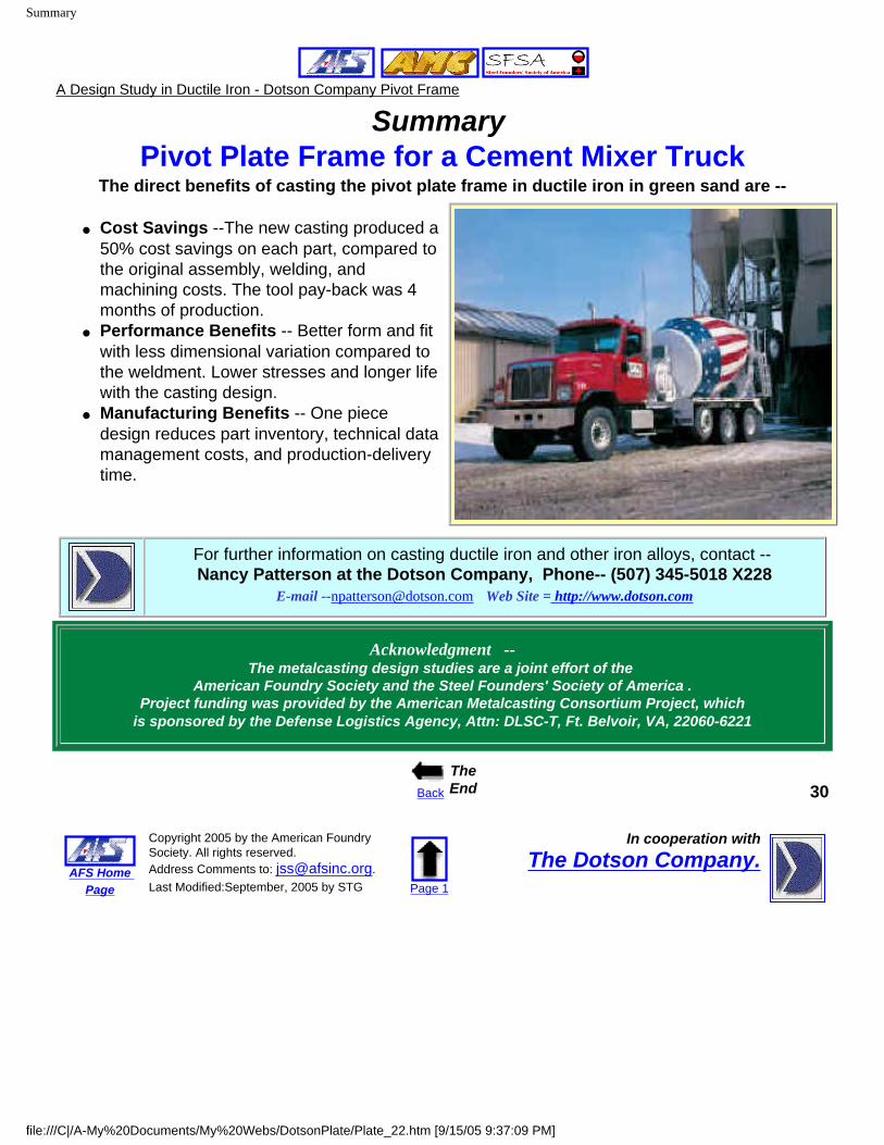
Summary Pivot Plate Frame for a Cement Mixer Truck
The direct benefits of casting the pivot plate frame in ductile iron in green sand are --
● Cost Savings --The new casting produced a 50% cost savings on each part, compared to the original assembly, welding, and machining costs. The tool pay-back was 4 months of production.
● Performance Benefits -- Better form and fit with less dimensional variation compared to the weldment. Lower stresses and longer life with the casting design.
● Manufacturing Benefits -- One piece design reduces part inventory, technical data management costs, and production-delivery time.
For further information on casting ductile iron and other iron alloys, contact -- Nancy Patterson at the Dotson Company, Phone-- (507) 345-5018 X228
E-mail [email protected] Web Site = http://www.dotson.com
Acknowledgment --The metalcasting design studies are a joint effort of the
American Foundry Society and the Steel Founders' Society of America .Project funding was provided by the American Metalcasting Consortium Project, which
is sponsored by the Defense Logistics Agency, Attn: DLSC-T, Ft. Belvoir, VA, 22060-6221
Back
The End 30
AFS Home Page
Copyright 2005 by the American Foundry Society. All rights reserved. Address Comments to: [email protected]. Last Modified:September, 2005 by STG Page 1
In cooperation withThe Dotson Company.
file:///C|/A-My%20Documents/My%20Webs/DotsonPlate/Plate_22.htm [9/15/05 9:37:09 PM]