standard operating procedures (sops) for the indiana corn ... · standard operating procedures...
TRANSCRIPT

Standard Operating Procedures (SOPS) for the
Indiana Corn and Soybean Innovation Center
The following SOP’s should be used to familiarize yourself with the equipment. Most of the equipment at ICSC will also require hands on training.
Below is a list of contacts in case of an emergency.
Emergency Contacts for Indiana Corn and Soybean Innovation Center (ICSC) Dial 911 for Red Light Emergency Facility Address: Indiana Corn and Soybean Innovation Center (ICSC) Agronomy Center for Research and Education (ACRE) 4750 US Hwy 52 West West Lafayette, IN 47906 If you're not sure, you can call Purdue Police non-emergency number and tell them the problem 494-8221.
Jason Adams, Facility Manager Office: 494-2007 Cell: 765-491-1264
Purdue Dept. of Radiological & Environmental Management, REM (Safety and spills): 494-6371 For a serious problem with the building that you can't contact Jason about, call Purdue Police non-emergency number 494-8221. They will page a maintenance person who is on-call.
1
ICSC Standard Operating Procedures (SOP)
TABLE OF CONTENTS
GENERAL FACILITY PROCEDURES……………………………………………………........ RESERVING EQUIPMENT………………………………………………………………….....F001
CAMFIL DUST COLLECTOR FILTERS……………………………………………………..F002
OUTSIDE COLLECTION BINS………………………………………………………………..F003
PHENOMICS VACCUM SYSTEM…………………………………………………………….F004
HIGH BAY RADIENT HEAT…………………………………………………………………..F005
TRANSPORTATION/MOVING………………………………………………………………… FORKLIFT………………………………………………………………………………………T001
WALKIE STACKER……………………………………………………………………………T002
PALLETT JACK………………………………………………………………………………...T003
DRYING AND STORAGE……………………………………………………………………….. BULK DRYING……………………………………………………….……………………….DS001
POST HARVEST SORAGE………………………………………….………...……………..DS002
WISCONSIN OVENS………………………………………………….………………………DS003
THRESHING AND SHELLING…………………………………………………………………. ALMACO TRUNKLINE…………………………….…………………………………………TS001
ALMACO MAIZER……………………………………………………………………………..TS002
ALMACO BT-14 SOYBEAN THRESHER……………………………………………………TS003
AGRICULEX SINGLE EAR SHELLER……………………………...………………………TS004
ALMACO HEAD THRESHER………………………...………………………………...…….TS005
ALMACO DOWN DRAFT TABLE…………...……………………………………………….TS006
CLEANING………………………………………………………………………………………... ROOT WASHING STATIONS………………………………………………………………….C001
CARTER DAY ASPERATOR………………………………………………………………..…C002
SEED SHAKER……………………...………………………………………………………...…C003
ALMACO SEED BED CLEANER……………………………………………...………………C004
2
ICSC Standard Operating Procedures (SOP)
TABLE OF CONTENTS
COUNTING/TREATING………………………………………………………………………... AGRICULEX SEED COUNTER…………………………………………………………….CT001
COUNTER/COLOR AND SHAPE SORTER……………………………………………….CT002
OLD MILL SEED COUNTER……………………………………………………………….CT003
SEED TREATER………………………………………….…………………………………..CT004
GRINDING………………………………………………………………………………………… LARGE SEED AND PLANT GRINDERS…………………………………………………....G001
UDY GRINDERS…………………………………………………………………………….....G002
MEASURING………………………………………………………………………………………
SCALES…………...............................................……...……..…………………………………M001
PHENO ROVER………………………………………………………………………………..M002
DICKEY JOHN……………………………………………………………………………...…M003
EAR PHOTPMETRY………………………………………………………………………….M004
ROOT SCANNER………………………………………………………...………………...….M005
LEAF AREA INDEXER (LAI)………………………………………………………………..M006
MOBILE SEED LAB…………………………………………………………………………..M007
NIR………………………………………………………………………………………………M008
3D SCANNER…………………………………………………………………………………..M009
TRIMBLE RTK BASE STATION……………………………………………………………M010
PRINTING………………………………………………………………………………………… PACKET PRINTER…………………………………………………………………………….P001
STAKE PRINTER……………………………………………………………………………....P002
3D PRINTER…………………………………………………………………………………….P003
Reserving Equipment Agronomy Department ACRE Innovation Center
SOP # ICSC F001
Revision # 3
Implementation Date 5/10/17
Page # 1 of 3 Last Update Date 7/29/19
SOP Owner ICSC Author Jason Adams
Documents: SOP short-form
Standard Operating Procedure – Reserving Equipment 1. Purpose
The purpose of this SOP is to give instruction on how to reserve certain pieces of equipment at the Innovation Center. 2. Scope
Anyone who may need to reserve equipment in the Innovation Center. 3. Prerequisites Must go through Innovation Center guidelines and watch facility safety and procedural videos online. 4. Responsibilities
PIs, Technicians, grad students, undergrads, University employees, faculty, farm staff. 5. Safety Concerns
• none
6. Procedure
1. You will first need to be trained on ICSC safety procedures as well as
equipment specific procedures. 2. After completion of all traing procedures. The facility manager will send an
email outlining the steps to set up iLabs. Which is the platform for reserving equipment.
To register for an account: To get started, you must register for an account:
Reserving Equipment Agronomy Department ACRE Innovation Center
SOP # ICSC F001
Revision # 3
Implementation Date 5/10/17
Page # 2 of 3 Last Update Date 7/29/19
SOP Owner ICSC Author Jason Adams
Documents: SOP short-form
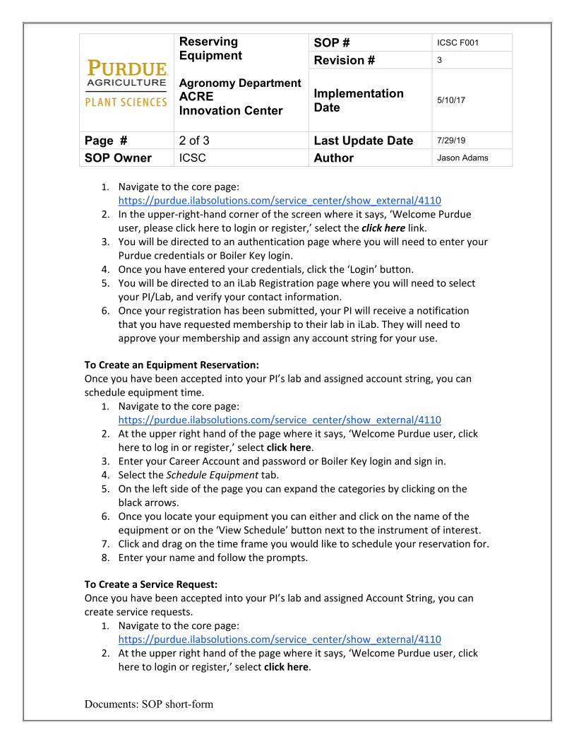
1. Navigate to the core page: https://purdue.ilabsolutions.com/service_center/show_external/4110
2. In the upper-right-hand corner of the screen where it says, ‘Welcome Purdue user, please click here to login or register,’ select the click here link.
3. You will be directed to an authentication page where you will need to enter your Purdue credentials or Boiler Key login.
4. Once you have entered your credentials, click the ‘Login’ button. 5. You will be directed to an iLab Registration page where you will need to select
your PI/Lab, and verify your contact information. 6. Once your registration has been submitted, your PI will receive a notification
that you have requested membership to their lab in iLab. They will need to approve your membership and assign any account string for your use.
To Create an Equipment Reservation: Once you have been accepted into your PI’s lab and assigned account string, you can schedule equipment time.
1. Navigate to the core page: https://purdue.ilabsolutions.com/service_center/show_external/4110
2. At the upper right hand of the page where it says, ‘Welcome Purdue user, click here to log in or register,’ select click here.
3. Enter your Career Account and password or Boiler Key login and sign in. 4. Select the Schedule Equipment tab. 5. On the left side of the page you can expand the categories by clicking on the
black arrows. 6. Once you locate your equipment you can either and click on the name of the
equipment or on the ‘View Schedule’ button next to the instrument of interest. 7. Click and drag on the time frame you would like to schedule your reservation for. 8. Enter your name and follow the prompts.
To Create a Service Request: Once you have been accepted into your PI’s lab and assigned Account String, you can create service requests.
1. Navigate to the core page: https://purdue.ilabsolutions.com/service_center/show_external/4110
2. At the upper right hand of the page where it says, ‘Welcome Purdue user, click here to login or register,’ select click here.
Reserving Equipment Agronomy Department ACRE Innovation Center
SOP # ICSC F001
Revision # 3
Implementation Date 5/10/17
Page # 3 of 3 Last Update Date 7/29/19
SOP Owner ICSC Author Jason Adams
Documents: SOP short-form
3. Enter your Career Account and password or Boiler Key and sign in. 4. Select the Request Services tab and click on the ‘Request Service’ button next to
the service of interest. 5. You will be asked to complete a form before submitting the request to the core. 6. Your request will be pending review by the core. The core will review your
request and either Agree to the work or they will ask for more information if needed.
Starting the Equipment once it is reserved:
1. When you are ready to start your equipment after you reserve it. Go back to the home page for ICSC in iLabs.
2. Click on the Kiosk Link. a. This can be done from any computer at ICSC or your computer. There is
not an app to do this but the website may be accessed from any device to start the machine.
3. Once you click on the Kiosk, you should see the equipment that you have reserved with a green start button.
4. Press start and this will power up your machine. 5. When you are done working return to the Kiosk page and press finished on your
machine. If you do not click finish when you are done you may be charged for overage.
7. References
Please watch the instructional video or see Innovation Center Facility manager. 8. Definitions
ACRE – Agronomy Center for Research and Education PI – Principal Investigator Seed Counter – A piece of equipment used for counting seed SOP – Standard Operating Procedure
Changing Camfil Dust Collector Filters Agronomy Department ACRE Innovation Center
SOP # ICSC F002
Revision # 2
Implementation Date 6/22/16
Page # 1 of 3 Last Update Date 7/30/19
SOP Owner ICSC Author Jason Adams
Documents: SOP short-form
Standard Operating Procedure – Camfil Dust Collector Filters 1. Purpose
The purpose of this SOP is to give instruction on how to change the Camfil Dust Collector Filters at the Innovation Center. 2. Scope
For those qualified to change the filters. 3. Prerequisites
Must be knowledgeable enough with the Camfil dust collectors to change the filters. 4. Responsibilities
Innovation Facility staff facility staff, farm staff, Purdue Building Maintenance personnel 5. Safety Concerns
• Falls • dust • Pinch points • Electrical shock • Compressed air
6. Procedure
1. Disconnect electrical power to the fan and control box. Disconnect
compressed air service from the compressed air header. Bleed all air from
Changing Camfil Dust Collector Filters Agronomy Department ACRE Innovation Center
SOP # ICSC F002
Revision # 2
Implementation Date 6/22/16
Page # 2 of 3 Last Update Date 7/30/19
SOP Owner ICSC Author Jason Adams
Documents: SOP short-form
the air header. Perform an OSHA approved LOTO procedure on these or any other energy source.
2. Open the access door at the front of the unit, swinging it out of the way. 3. Rotate the left side clamp bar counter clockwise and pull toward you until
it clears the clamp bar clockwise until it resets on the bottom of the HEPA filter module.
4. Rotate the right-side clamp bar clockwise and pull toward you until it clears the clamp bar latch bracket. Then rotate the clamp bar counter clockwise until it rests on the bottom of the HEPA filter module.
5. Pull the first filter out by sliding it off the clamp bar tubes. 6. Pull the second filter out. 7. If the dust collector is equipped with filters behind the front filters. First
remove the front filters as mentioned above. Then use the long-handled tool attached to the dust collector to reach the other filters.
8. Remove a new filter from the shipping carton, taking care not to cut or otherwise damage the filter. With the gasket side up, place the bottom edge of the filter on the clamp bar tubes. Push the filter in until it reaches the filter stop at the end of the clamp bar tube.
9. Slide the filter spacer onto the clamp bars, the “tag” must be down (if equipped).
10. Install the second filter, push the filter in until the spacer is tight against the back filter and the front filter is tight against the spacer.
11. To seal the filters, repeat steps 2 and 3 in reverse order. Visually check the gasket to make sure it is compressed when the clamp bars are latched.
7. Lockout Tagout Procedures
1. Place a lock and tag on the front panel of the dust collector you are
working on. 2. Place a lock on the compressed air shut-off either near where the airlines
pass the gutter or on the north wall of ICSC. 3. Turn equipment on and off to check if all the power sources have been
shut down. 4. Perform maintenance. 5. Remove lock and tag from airline.
Changing Camfil Dust Collector Filters Agronomy Department ACRE Innovation Center
SOP # ICSC F002
Revision # 2
Implementation Date 6/22/16
Page # 3 of 3 Last Update Date 7/30/19
SOP Owner ICSC Author Jason Adams
Documents: SOP short-form
6. Remove lock and tag from electrical shut-off. 8. References
Please see Innovation Center Facility manager for instructions or owner’s manual. 9. Definitions
ACRE – Agronomy Center for Research and Education LOTO – Lockout Tagout. The act of locking a machine or device so it may not be
energized during maintenance SOP – Standard Operating Procedure
Outside Collections Bins Agronomy Department ACRE Innovation Center
SOP # ICSC F003
Revision # 3
Implementation Date 6/22/16
Page # 1 of 2 Last Update Date 7/31/19
SOP Owner ICSC Author Jason Adams
Documents: SOP short-form
Standard Operating Procedure – Outside Collection Bins 1. Purpose
The purpose of this SOP is to give instruction on how to empty the large dust and ground plant material bins at the Innovation Center. 2. Scope
For those needing to empty the large bins. The preferred method would be to contact the facility manager. If that is not an option. Any Purdue forklift trained operator may empty the bins. 3. Prerequisites
Must be Purdue forklift certified. 4. Responsibilities
PIs, Technicians, grad students, undergrads, faculty, farm staff, university employees. 5. Safety Concerns
• Pinch points • Falling Bin from forklift • Heavy Lifting
6. Procedure
1. Shut the dust collector hopper by pushing in the long black handle on the
bottom of the dust collector cone. This prevents debris from coming out while bin is being rolled away and the dust collector will remain operational for a small amount of time while bin is being emptied.
2. Remove the connecting tube by releasing the large gray snap ring.
Outside Collections Bins Agronomy Department ACRE Innovation Center
SOP # ICSC F003
Revision # 3
Implementation Date 6/22/16
Page # 2 of 2 Last Update Date 7/31/19
SOP Owner ICSC Author Jason Adams
Documents: SOP short-form
3. Use the three small chains to hold up the connecting tube. 4. Use forklift to pull dump bin away from dust collector. Do not use Walkie
Stacker. 5. Release the two large binders and open the lid to the dump hopper. 6. Use the large chain to hold the dump hopper lid open. 7. Release the safety latch at the back of the bin. 8. Pick up the dump hopper with the forklift from behind the dump hopper. 9. Lift the dump hopper over the large roll off trash bin. 10. Either release the rocking mechanism by pulling on the cable or by lightly
tapping the paddle on the front of the dump hopper to the roll of dumpster. 11. After the bin has been emptied, place it back on the ground. 12. Manually roll bin back into upright position 13. Latch the back safety latch. 14. Latch the two large lid binders. 15. Place the bin back under the dust collector 16. Un-hook the chains and snap the tube back in place. 17. Open the hatch by pulling the black handle back out.
7. References
Please see Innovation Center manager for instructions. 8. Definitions
ACRE – Agronomy Center for Research and Education SOP – Standard Operating Procedure
Phenomics Vacuum System Agronomy Department ACRE Innovation Center
SOP # ICSC F004
Revision # 2
Implementation Date 5/4/17
Page # 1 of 2 Last Update Date 8/1/19
SOP Owner ICSC Author Jason Adams
Documents: SOP short-form
Standard Operating Procedure – Phenomics Vacuum System 1. Purpose
The purpose of this SOP is to give instruction on how to operate the Vacuum System at the Innovation Center. 2. Scope
Anyone who has a need to run the vacuums. 3. Prerequisites
Must go through Innovation Center guidelines and watch facility safety and procedural videos online. 4. Responsibilities
PIs, Technicians, grad students, undergrads, University employees, faculty, farm staff. 5. Safety Concerns
• none
6. Procedure
1. The central vacuums are located in rooms 1168 and 1136. 2. Retrieve the vacuum lines from the wall mount. 3. Obtain the desired attachment from the accessory basket. 4. Hook the hose to one of the vacuum ports. 5. Turn the green “Systems on Button” Located on the wall. 6. Proceed to vacuum. 7. When complete press the red “Systems off” button. 8. Return the hose and accessories to the wall brackets.
Phenomics Vacuum System Agronomy Department ACRE Innovation Center
SOP # ICSC F004
Revision # 2
Implementation Date 5/4/17
Page # 2 of 2 Last Update Date 8/1/19
SOP Owner ICSC Author Jason Adams
Documents: SOP short-form
7. Lockout Tag out Procedure
1. Obtain key to the vacuum cage from the facility manager. 2. Locate the blue switch on the main vacuum electrical panel located
outside under the back porch. 3. Place appropriate lock and tag the device. 4. Lock out the air supply. 5. Do a check to confirm the power and air supply has been shut off. 6. Perform maintenance. 7. Remove locks and tags.
8. References
Please see Innovation Center manager for instructions or access to the owner’s manual. 9. Definitions
ACRE – Agronomy Center for Research and Education LOTO – Lockout Tag out. The act of locking a machine or device so it may not be
energized during maintenance PI – Principal Investigator SOP – Standard Operating Procedure
High Bay Radiant Heat Agronomy Department ACRE Innovation Center
SOP # ICSC F005
Revision # 1
Implementation Date 5/9/17
Page # 1 of 2 Last Update Date 7/20/17
SOP Owner ICSC Author Jason Adams
Documents: SOP short-form
Standard Operating Procedure – High Bay Radiant Heat 1. Purpose
The purpose of this SOP is to give instruction on how to run the high bay radiant heat at the Innovation Center. 2. Scope
Anyone who may need to operate the high bay radiant heat in the Innovation Center. 3. Prerequisites Must go through Innovation Center guidelines and watch facility safety and procedural videos online. 4. Responsibilities
PIs, Technicians, grad students, undergrads, University employees, faculty, farm staff. 5. Safety Concerns
• none
6. Procedure
1. There are 8 different radiant heating units in the Highbay room of ICSC 2. Each unit is run independently with its own timer 3. To operate locate the timer that is near the heater mounted on the large
steel beam 4. Turn the dial to desired length of time. 30 minutes max. 5. The heater will turn off automatically at the end of the set time
High Bay Radiant Heat Agronomy Department ACRE Innovation Center
SOP # ICSC F005
Revision # 1
Implementation Date 5/9/17
Page # 2 of 2 Last Update Date 7/20/17
SOP Owner ICSC Author Jason Adams
Documents: SOP short-form
6. Repeat the steps to turn it on again 7. References
Please watch the instructional video or see Innovation Center Facility manager for instructions or access to the owner’s manual 8. Definitions
ACRE – Agronomy Center for Research and Education High Bay – The tall part of the Innovation Center used to work on UAVs and the
Phenomobile or other field sensors PI – Principal Investigator Seed Counter – A piece of equipment used for counting seed SOP – Standard Operating Procedure
Forklift Agronomy Department ACRE Innovation Center
SOP # ICSC T001
Revision # 2
Implementation Date 5/4/17
Page # 1 of 5 Last Update Date 8/5/19
SOP Owner ICSC Author Jason Adams
Documents: SOP short-form
Standard Operating Procedure – Forklift
1. Purpose
The purpose of this SOP is to give instruction on how to start and operate the ACRE/Innovation Center facility forklift safely. 2. Scope
Anyone who has a need and is Purdue trained and licensed to run a Forklift. The only room at the Innovation Center facility that the forklift is allowed in is the high bay and the hard surfaces surrounding the building. 3. Prerequisites
Must be Purdue forklift certified to use the forklift at ACRE or the Innovation Center facility. Also, must go through Innovation Center facility guidelines and watch facility safety and procedural videos online. 4. Responsibilities
• Supervisors o Ensure that all employees under their direction who are designated
to operate a forklift are trained, evaluated, and certified prior to operation of the equipment. Ensure that certification is kept current (e.g., re-evaluation/driving test and refresher training, as applicable) and notify REM of employees who are no longer employed with their department or whose job has changed and are no longer assigned to operate a forklift as part of their duties. Notify REM of accidents and near misses involving forklift operation. Ensure that forklifts and attachments are appropriate for the use conditions and maintained in safe operating condition. Immediately remove defective equipment from service until repaired or replaced. To the extent feasible, reduce operational hazards presented by the use location and loads.
• Employees
Forklift Agronomy Department ACRE Innovation Center
SOP # ICSC T001
Revision # 2
Implementation Date 5/4/17
Page # 2 of 5 Last Update Date 8/5/19
SOP Owner ICSC Author Jason Adams
Documents: SOP short-form
o Complete all components of training at the required intervals. Complete classroom and hands-on training, and demonstration of competency in operation. Conduct pre-operational inspections prior to start of each shift. Do not operate a forklift that does not successfully pass the pre-operational checklist. Immediately stop operating any defective forklift or attachment and report the situation to the supervisor. Read the manufacturer’s operations manual. Observe all precautions discussed in training and the recommendations of the manufacturer of the forklift.
5. Safety Concerns
• Pinch points • Running over feet • Falling bins, pallets • Tipping • Running into objects, people • Overhead clearance • Getting stuck in soft surfaces
6. Procedure
Before Operation
1. Only trained personnel with current authorization are allowed to operate Forklifts. Authorization requires successful completion of initial classroom training, hands-on work-area specific training (practical), and a driving test (evaluation).
2. Passengers are not permitted on or in the forklift or load. 3. Daily visual inspection must be made to ensure that the horn, lights,
brakes, tires, gas supply, hydraulic lines, etc. are in safe working condition. Employees may not operate an unsafe forklift at any time.
4. Fill fuel tanks out of doors while the engine is off. 5. Operators must wear seatbelts
Picking up a load
Forklift Agronomy Department ACRE Innovation Center
SOP # ICSC T001
Revision # 2
Implementation Date 5/4/17
Page # 3 of 5 Last Update Date 8/5/19
SOP Owner ICSC Author Jason Adams
Documents: SOP short-form
6. Do not exceed the safe load capacity of a forklift at any time. Do not
counterweight a forklift to increase its lifting capacity. 7. Forks should always be placed under the load as far as possible.
Do not lift a load with one fork. 8. No load should be moved unless it is absolutely safe and secure. 9. When unloading trucks or trailers, the brakes on the vehicle must
be set (locked) and the wheels chocked. 10. No person is permitted to stand or walk under elevated forks.
Moving the load
11. The operator's view should not be obstructed by the load. In the event of a high load, the forklift should be driven in reverse.
12. Operators must look in the direction of travel. 13. The forks should not be operated while the forklift is traveling. 14. When the forklift is not carrying a load, the operator must travel with
the forks as low as possible (maximum of 4 inches on paved surfaces). When carrying a load, it should be carried as low as possible (consistent with safe operation, 3 to 12 inches above the surface).
15. On a downgrade, the forklift should be driven in reverse, and the forks raised only enough to clear the surface.
16. On an upgrade, the forklift must be driven in the forward direction, following the load, and the forks raised only enough to clear the surface.
17. Use extra care when handling long lengths of bar stock, pipe, or other materials.
18. Avoid sharp or fast end-swings. 19. Operators should avoid making jerky starts, quick turns, or sudden
stops. The operator is not permitted to use reverse as a brake. 20. Forklifts should be driven on the right side of the road or aisle-way. 21. Forklifts must be operated at a safe speed with due regard for
traffic and conditions. 22. Slow down on wet and slippery surfaces and at cross aisles or
locations where vision is obstructed. 23. Operators entering a building or nearing a blind corner must make
their approach at reduced speed, sound the horn, and proceed carefully.
Forklift Agronomy Department ACRE Innovation Center
SOP # ICSC T001
Revision # 2
Implementation Date 5/4/17
Page # 4 of 5 Last Update Date 8/5/19
SOP Owner ICSC Author Jason Adams
Documents: SOP short-form
24. Operators must give pedestrians the right-of-way at all times. 25. Operators must not drive toward any person who is in front of a
fixed object or wall. 26. Operators should not put their fingers, arms, or legs between the
uprights of the mast, or beyond the contour of the forklift. 27. Operators must drive with both hands on the steering wheel.
Horseplay is prohibited. Do not drive with wet or greasy hands. 28. No person is permitted to ride as a passenger on a forklift or on the
load being carried. Parking
29. Forklifts must be safely parked when not in use. The controls must be neutralized, power shut off, brakes set, key removed, and the forks secured in a lowest position, flat on the surface, and not obstructing walkways or aisles.
30. A forklift may not be left on an incline 31. Forklifts may not be parked in areas that will block exits, stairways,
fire extinguishers or any other emergency equipment
7. Lockout Tag out Procedures
1. Set parking break. 2. Remove the key. 3. Place key in lock box with your lock and tag on it. 4. Insure that there is no stored power in the machine. 5. Perform maintenance. 6. Remove lock and tag.
8. References
Please see Innovation Center Facility manager for assistance or access to the owner’s manual 9. Definitions
ACRE – Agronomy Center for Research and Education
Forklift Agronomy Department ACRE Innovation Center
SOP # ICSC T001
Revision # 2
Implementation Date 5/4/17
Page # 5 of 5 Last Update Date 8/5/19
SOP Owner ICSC Author Jason Adams
Documents: SOP short-form
LOTO – Lockout Tagout. The act of locking a machine or device so it may not be energized during maintenance
PI – Principal Investigator SOP – Standard Operating Procedure
Walkie Stacker Agronomy Department ACRE Innovation Center
SOP # ICSC T002
Revision # 2
Implementation Date
6/22/16
Page # 1 of 4 Last Update Date 8/6/19
SOP Owner ICSC Author Jason Adams
Documents: SOP short-form
Standard Operating Procedure - Walkie Stacker 1. Purpose
The purpose of this SOP is to give instruction on how to start, operate and charge the Walkie Stacker at the Innovation Center. 2. Scope
Anyone who has a need and is Purdue trained and licensed to run a Forklift or Walkie Stacker. The Walkie Stacker is only to be used in the ICSC Facility receiving room, the high bay and the hard surfaces to the north of the facility. It should not be operated in any other room within the facility. 3. Prerequisites
Must be Purdue forklift certified to use the Walkie Stacker. Also, must go through Phenomics facility guidelines and watch facility safety and procedural videos online. 4. Users
PIs, Technicians, grad students, undergrads, faculty, university employees and farm staff. 5. Safety Concerns
• Pinch points • Running over feet, being struck by Walkie Stacker • Falling bins, pallets • Running into people, building, objects, vehicles • Falls and tip overs • Battery explosions
Walkie Stacker Agronomy Department ACRE Innovation Center
SOP # ICSC T002
Revision # 2
Implementation Date
6/22/16
Page # 2 of 4 Last Update Date 8/6/19
SOP Owner ICSC Author Jason Adams
Documents: SOP short-form
6. Operating Procedure
1. Perform a general walk around to determine if Walkie Stacker is in good working order. Check the following items:
a. Battery is charged b. Wheels are in good condition c. Check both forks to see if they are worn, bent or broken d. Inspect lift chains for damage e. Check load backrest is in place and secure f. Look under truck for hydraulic leaks g. Test the horn h. Check that all control levels work smoothly
2. If at any time you see a defect or have a concern, contact the ICSC facility manager.
3. Remove the Walkie Stacker key form the lock box. 4. Turn the truck on by placing the control handle vertical and turning the key
ON (green dot). 5. Braking: Move the control handle all the way down or all the way up to
apply the brake (see Brake Zone Label). When you let go of the control handle it will automatically go to the upper braking zone.
6. To Raise: Push the Raise Button and release when the forks are at the desired height.
7. To Lower: Push the lower button all the way for fast lowering. Push the button part of the way for slower lowering speed. Release the button when the forks at the desired height.
8. To Tilt: Push the top of the Tilt switch to tilt the tip of the forks up; Push the bottom of the Tilt switch to tilt the tip of the forks down.
9. To Reach: Push of the Reach switch to extend the forks. Push the bottom of the switch to retract the forks.
10. Load: Make sure the load is secure, level and not too heavy for the Walkie Stacker to handle.
11. Steering: You control the steering by moving the control handle from side to side.
12. Travel: Move either Forward/Reverse Rocker in the direction you want to move. The farther you move the rocker from the neutral position, the faster the truck will move. For high travel speed, turn the travel speed switch to the high speed position ( ), and move either the Forward/Reverse rocker to the maximum travel speed position.
Walkie Stacker Agronomy Department ACRE Innovation Center
SOP # ICSC T002
Revision # 2
Implementation Date
6/22/16
Page # 3 of 4 Last Update Date 8/6/19
SOP Owner ICSC Author Jason Adams
Documents: SOP short-form
13. When operating the Walkie Stacker in the forward position the recommended walking area is directly behind the control handle. While the Walkie Stacker is traveling in the reverse direction the recommended walking area is directly to the right or left of the walkie stacker to prevent being run over by the Walkie Stacker.
14. Plugging: This is another way to slow or stop the Walkie Stacker. While the truck is in motion in either direction, move the Forward/Reverse rocker to the opposite direction that you are traveling. Plugging will not hurt the Walkie Stacker.
15. Reversing Button: The reversing button is located at the end of the control handle. If you accidentally hit the reversing button while working in close quarters, the truck will move in the direction of the forks until the button is released. The reversing button cannot prevent all injuries.
16. Horn: Push the switch on the underside of either grip to sound the horn. Use the horn to warn pedestrians and other drivers. Use your horn when you come to an intersection or cross walk.
17. Charging: When the Battery Charge Display is showing a yellow light it is time to charge the Walkie Stacker. Park the Walkie Stacker in the designated spot in the receiving room. Turn the Walkie Stacker off. Do not disconnect the battery. Open the battery access panel on top of the Walkie Stacker. Use the provided extension cord and plug it into the nearby wall outlet.
18. Charging Light Status: a. Steady Yellow Light: If the light does not come on, or goes out,
make sure the AC outlet is working and the extension cord is OK. b. Flashing Yellow Light: Means the something is wrong with the
battery or the charger. Notify ICSC manager. c. Flashing Green Light: Means the charger is working. d. Steady Green Light: Means charger is finished
19. Place the key back in the lock box when done with the Walkie Stacker. 7. Lockout Tag Out Procedures
1. Remove Key, then place the key in LOTO box. 2. Place lock on LOTO box.. 3. Fill out LOTO tag and report to Facility Manager. 4. Check to see if all energy sources have been isolated.
Walkie Stacker Agronomy Department ACRE Innovation Center
SOP # ICSC T002
Revision # 2
Implementation Date
6/22/16
Page # 4 of 4 Last Update Date 8/6/19
SOP Owner ICSC Author Jason Adams
Documents: SOP short-form
5. Perform maintenance. 6. To remove LOTO. Unlock the box and place the key back in the Walkie
Stacker. 8. References
Please see Phonemics Facility manager for assistance or access to the owner’s manual 9. Definitions
ACRE – Agronomy Center for Research and Education LOTO – Lockout Tag out. The act of locking a machine or device so it may not be
energized during maintenance PI – Principal Investigator SOP – Standard Operating Procedure Walkie-Stacker – Battery powered walk behind pallet jack with the capabilities to
stack bins or pallets on shelves
Pallet Jacks Agronomy Department ACRE Innovation Center
SOP # ICSC T003
Revision # 1
Implementation Date 6/22/16
Page # 1 of 2 Last Update Date 7/6/17
SOP Owner ICSC Author Jason Adams
Documents: SOP short-form
Standard Operating Procedure – Pallet Jacks 1. Purpose
The purpose of this SOP is to give instruction on how to operate a Pallet Jack at the Innovation Center. 2. Scope
Anyone who has a need to move pallets, bins or skids at the Innovation Center. Please do not use Pallet Jacks in the long hallway of the facility to prevent any damage to the floors or glass walls. 3. Prerequisites
Must go through Innovation Centers guidelines and watch facility safety and procedural videos online. 4. Responsibilities
PIs, Technicians, grad students, undergrads, faculty, farm staff, university employees.
5. Safety Concerns • Pinch points • Running over feet • Running into something
6. Procedure
1. Place forks of the pallet jack into position under or in the pallet or bin. 2. Lift the load by pushing the lever under the handle down or in the forward
position. Then pump the handle until the load is lifted of the floor. 3. To travel with the load place the lever in the middle or neutral position.
Then either push or pull the load to desired location. 4. To lower the load pull the lever up toward the handle until the load has
lowered to the floor. 5. Pull pallet jack from under the load.
Pallet Jacks Agronomy Department ACRE Innovation Center
SOP # ICSC T003
Revision # 1
Implementation Date 6/22/16
Page # 2 of 2 Last Update Date 7/6/17
SOP Owner ICSC Author Jason Adams
Documents: SOP short-form
7. References
Please see Innovation Centers manager for assistance or access to the owner’s manual 8. Definitions
PI – Principal Investigator SOP – Standard Operating Procedure Pallet Jack – Manual powered equipment for lifting pallets or bins of the ground
and moving them around.
Bulk Dryer Agronomy Department ACRE Innovation Center
SOP # ICSC DS001
Revision # 2
Implementation Date 6/22/16
Page # 1 of 3 Last Update Date 8/6/19
SOP Owner ICSC Author Jason Adams
Documents: SOP short-form
Standard Operating Procedure - Bulk Dryer 1. Purpose
The purpose of this SOP is to give instruction on how to load, log and operate the large bin dryers at the ACRE facility. 2. Scope
Anyone who has a need to dry plant or seed material and is forklift licensed at Purdue University. The bins must be loaded in a way that encourages airflow. Meshed bags work better for airflow than paper bags. 3. Prerequisites
Must be forklift certified to load the bins on the dryers. 4. Responsibilities
PIs, Technicians, grad students, faculty, farm staff. 5. Safety Concerns
• Falling lids • Falling drying bins • Pinch points
6. Procedure
1. Contact Jason Adams at ICSC to turn on the dryers if they are not already
running 765-494-2007. 2. Label white drying bin with project owner and date the bin was placed on
dryer with duct tape located in mailbox next to the dryers. 3. Determine which dryers you want to use.
Bulk Dryer Agronomy Department ACRE Innovation Center
SOP # ICSC DS001
Revision # 2
Implementation Date 6/22/16
Page # 2 of 3 Last Update Date 8/6/19
SOP Owner ICSC Author Jason Adams
Documents: SOP short-form
a. 140°F for Plant material b. 90°F for seed
4. Remove bin cover from the dryer. 5. Carefully place the bin onto the dryer making sure it is completely nested
on the dryer. a. Never place the bins more than three high on the dryer. b. It is best to place newer/wetter material on top of multiple staked
bins. If you place wetter material on the bottom and dryer material on top. The moisture from the bottom will be forced through the dryer bins on top.
6. Replace bin cover. 7. On the backside of the dryer, make sure the vents are open. By turning
the wheeled crank. a. Please make sure the vents are open for at least two of the bin
bays while dryer is running. This prevents excessive airflow backup into the blower fans.
8. If you are taking the last bin off the dryer then please contact Jason Adams to turn off the dryer 765-494-2007.
9. Return all bay covers when you are done and close the vents in the back. 7 Lockout Tag out Procedures
1. Locate the blade switch associated with that dryer on the electrical service box.
2. Turn blade switch off and place your lock and tag on. 3. Locate the shutoff for the gas. 4. Turn the gas off and lock and tag the gas. 5. Check to see if there is any stored energy. 6. Perform maintenance. 7. Remove the lock on the gas and turn on the gas 8. Remove the lock from the blade switch and turn on the power
8. References
Please see Phonemics Facility manger or ACRE staff with any questions.
Bulk Dryer Agronomy Department ACRE Innovation Center
SOP # ICSC DS001
Revision # 2
Implementation Date 6/22/16
Page # 3 of 3 Last Update Date 8/6/19
SOP Owner ICSC Author Jason Adams
Documents: SOP short-form
9. Definitions
ACRE – Agronomy Center for Research and Education ICSC – Indiana Corn and Soybean Innovation Center Drying Bins – Large white metal containers. Some are labeled AEC PI – Principal Investigator SOP – Standard Operating Procedure
Post-harvest Storage in East Shed Agronomy Department ACRE Innovation Center
SOP # ICSC DS002
Revision # 2
Implementation Date 6/22/16
Page # 1 of 2 Last Update Date 8/6/19
SOP Owner ICSC Author Jason Adams
Documents: SOP short-form
Standard Operating Procedure - Post-Harvest Storage in East Shed 1. Purpose
The purpose of this SOP is to give instruction on how to store large plastic bins and other research material in building 57 at the ACRE campus. 2. Scope
Anyone who has a need to store post-harvest seed or plant material at ACRE. 3. Prerequisites
If you will be moving bins around with a forklift than you must be trained and certified by Purdue to operate a forklift. Bins may be moved around in building 57 by using a pallet jack if stacking of bins is not necessary. 4. Responsibilities
PIs, Technicians, grad students, faculty, farm staff. When you are done with the bins it is your responsibility to clean them out for the next user. Empty bins are stored in the East Shed. 5. Safety Concerns
• Crush hazard • Falling bins
6. Procedure
1. Place plant or seed into large 48in x 45in plastic bins or on the wooded drying racks.
a. Do not fill past the top of the bins to prevent your material from being crushed when stacked.
2. Label each bin with the owners name and date at a minimum. 3. Place bins in any available section in building 57.
Post-harvest Storage in East Shed Agronomy Department ACRE Innovation Center
SOP # ICSC DS002
Revision # 2
Implementation Date 6/22/16
Page # 2 of 2 Last Update Date 8/6/19
SOP Owner ICSC Author Jason Adams
Documents: SOP short-form
4. Stack bins in rows so that you can walk between them to find the correct bin numbers.
5. Do not stack bins more than 4 high. Less if the bins are heavy. a. When staking make sure the bins are nested properly and evenly
around all sides of the bins. 6. Try to place only material from one PI in a row. This will help with keeping
material sorted later. 7. References
Please see Phonemics Facility manger or ACRE staff with any questions 8. Definitions
East Shed – Building number 57 located just east of the bulk dryers PI – Principle Investigator SOP – Standard Operating Procedure
Wisconsin Ovens Agronomy Department ACRE Innovation Center
SOP # ICSC DS003
Revision # 1
Implementation Date 6/22/16
Page # 1 of 4 Last Update Date 7/23/18
SOP Owner ICSC Author Jason Adams
Documents: SOP short-form
Standard Operating Procedure – Wisconsin Oven 1. Purpose
The purpose of this SOP is to give instruction on how to operate the Wisconsin ovens at the Innovation Center. 2. Scope
Anyone who has a need to dry plant or seed material. 3. Prerequisites
Must go through Innovation Center guidelines and watch facility safety and procedural videos online. 4. Responsibilities
PIs, Technicians, grad students, undergrads, University employees, faculty, farm staff. 5. Safety Concerns
• Burns • Pinch points
6. Procedure
Start Up 1. Place the Main Disconnect switch “ON”. 2. Make sure the “Blower(s) Stop/Emergency Manual Off” button is pulled
out. 3. Place the “Control Power” selector switch to the “ON” position. The
“Control Power” light will be lit.
Wisconsin Ovens Agronomy Department ACRE Innovation Center
SOP # ICSC DS003
Revision # 1
Implementation Date 6/22/16
Page # 2 of 4 Last Update Date 7/23/18
SOP Owner ICSC Author Jason Adams
Documents: SOP short-form
4. Push the “Alarm Silence/Reset” button. 5. Push the “Blowers(s) start” button. 6. The “Safe Guards Met” light will be lit. 7. Adjust temperature controller to desired setting. 8. Place the “Heat” selector switch to “On” position. The “Heat On” light
will be lit. 9. When the process timer is in the “Alarm” position, the “Process
Complete” light will turn on and the horn will sound. When the process timer is in the “Shutdown” position, the “Process Complete” light will turn on and the oven will shut down.
Shut Down 1. Place the “Heat” selector switch to the “Off” position. 2. Allow the blower to run until the oven cools to below 200°F/93°C. 3. Push the “Blower(s) Stop/Emergency Manual Off” button. 4. Push the “Alarm Silencer/Reset” button. 5. Place the Control Power Switch “Off”. 6. Place the Main Disconnect switch “Off”.
Process Timer Turn the (3) position switch to one of the following modes. OFF
1. Start up the oven according to the startup instructions. 2. Shutdown the oven according to the shutdown instructions.
Process Alarm
1. Place load in oven. 2. Select the amount of process time required for your product and set the timer
accordingly. 3. Adjust the temperature controller to the desired setting. 4. When the temperature in the oven has reached the point temperature, the process
timer will start timing. 5. When the process timer times out, the alarm will sound. The oven heat will
continue to stay on.
Wisconsin Ovens Agronomy Department ACRE Innovation Center
SOP # ICSC DS003
Revision # 1
Implementation Date 6/22/16
Page # 3 of 4 Last Update Date 7/23/18
SOP Owner ICSC Author Jason Adams
Documents: SOP short-form
6. To restart the timer, turn the selector switch momentarily to the “Off” position. Shutdown
1. Place load in oven. 2. Select the amount of process time required for your product and set the timer
accordingly. 3. Adjust the temperature controller to the desired setting. 4. When the temperature in the oven has reached the set point temperature, the
process timer will start timing. 5. When the process timer times out, the heat will shut off. 6. After the heats shuts off and the oven begins to cool (when oven cools to 150°F.)
the circulation blower will shut down. 7. To restart the timer, turn the selector switch momentarily to the “Off” position.
Removal of shelving
1. Pull the shelving out until it reached the safety latch on the right side of the railing 2. Reach in and flip the safety latch up 3. Temporally store the shelving on the side of dryer A or behind dryer B
7. Lockout Tag out Procedures
1. Each oven has a blade switch. To lock out the oven flip the associated blade switch to off.
2. Place your lock and tag on the blade switch. 3. Test to see if the oven will come on. 4. Perform your work. 5. When work is complete, remove locks and tags. 6. Turn the blade switch back on.
8. References
Please see Innovation Center Facility manager for instructions or owner’s manual.
Wisconsin Ovens Agronomy Department ACRE Innovation Center
SOP # ICSC DS003
Revision # 1
Implementation Date 6/22/16
Page # 4 of 4 Last Update Date 7/23/18
SOP Owner ICSC Author Jason Adams
Documents: SOP short-form
9. Definitions
ACRE – Agronomy Center for Research and Education LOTO – Lockout Tag out. The act of locking a machine or device so it may not be
energized during maintenance PI – Principal Investigator SOP – Standard Operating Procedure
Almaco Trunk line Agronomy Department ACRE Innovation Center
SOP # ICSC TS001
Revision # 3
Implementation Date 9/7/16
Page # 1 of 4 Last Update Date 8/9/19
SOP Owner ICSC Author Jason Adams
Documents: SOP short-form
Standard Operating Procedure – Almaco Trunk line 1. Purpose
The purpose of this SOP is to give instruction on how to operate the Almaco Trunk Line at the Innovation Center. 2. Scope
Anyone who may need to run plant material through the Threshing and Shelling Room. 3. Prerequisites
Must go through Innovation Center guidelines and watch facility safety and procedural videos online. ICSC 101 and ICSC 140, 150, 160, 170 or 180 depending on the crop you will be processing. 4. Responsibilities
PIs, Technicians, grad students, undergrads, University employees, faculty, farm staff. 5. Safety Concerns
• Pinch points • Hearing protection • Eye protection
6. Procedure
Start Up 1. In the Threshing and Shelling room go to the Threshing Line Control
Panel. Located on the large gray box on the north wall.
Almaco Trunk line Agronomy Department ACRE Innovation Center
SOP # ICSC TS001
Revision # 3
Implementation Date 9/7/16
Page # 2 of 4 Last Update Date 8/9/19
SOP Owner ICSC Author Jason Adams
Documents: SOP short-form
2. Navigate to the Main Screen. Then start the line by touching the Auto Start up Screen in the lower left of the display.
a. Hit Start. This will start the Grinder, inside conveyer and Dust Collector C.
3. Next, determine what station you are working at. If the station is labeled with an “A” then you will need to turn on dust collection “A”. If the station is labeled with a “B” then you will need to turn on dust collection “B”. If you are working outside you will only need to turn on the outside conveyer.
4. To turn on the individual dust collectors or outside conveyer. Return to the Main Screen by touching Goto Main Screen in the lower right corner.
5. Then touch Goto Equip Screen. This will take you to the Equipment Overview screen.
6. To start either “A” or “B” dust collector touch Start up Dust Collector button. Then start either dust collector “A” or “B”. Whichever one is needed to run your work Station.
7. If you will be working, outside and need to start the outside conveyer return to the Equipment Overview screen. Then touch the Start up Grinder & Conv button. Then press Outside Conveyer Start.
8. To shut down the threshing and shelling line. Return to the Main Screen by touching GOTO Main Screen button
9. Then press Auto Start Up. 10. Then Press Stop. 11. NEVER RUN IN MAINTENACE MODE
E-Stops
If at any time, the E-Stops are used to turn equipment off. (These are the large red push buttons all around the equipment). The following steps will need to be done to get the equipment functional again.
1. Determine which E-Stop was engaged by either one of these two ways. a. Walking around and seeing which one has the red indicator light on
the button. Then to disengage, push down and turn clockwise. b. Or on the Threshing Line Control Panel. Navigate to the Main
Screen. i. Touch Goto Estop Screen ii. Navigate to either the Station Estop Screen button or the
Equip Estop button. In either screen if the dot next to the station or equipment is colored in black. Then that signifies that that Estop has been engaged. You will then need to go
Almaco Trunk line Agronomy Department ACRE Innovation Center
SOP # ICSC TS001
Revision # 3
Implementation Date 9/7/16
Page # 3 of 4 Last Update Date 8/9/19
SOP Owner ICSC Author Jason Adams
Documents: SOP short-form
to that Estop and disengage it by pushing down and turning clockwise.
2. Then on the Threshing Line Control Panel. Press the red Emergency Stop Reset button to the left of the touch display.
3. The final step to reset the Estops will be to go outside to the large dust collectors on the north side of the building. You will need to look at each dust collector and make sure the Control Power On button is on. If the green indicator light on that button is not lit then press the button until the green light comes on.
7. Lockout Tagout Procedure
1. Place one lock and tag on the throw off switch on the Threshing Line Control Panel.
2. Place one lock and tag on either or both of the airlines to the east of the Threshing Line Control Panel.
3. Confirm that there is no stored energy. 4. Perform maintenance. 5. To turn the equipment back on remove the locks and tags on the air lines. 6. Remove the locks and tags on the throw switch. 7. Turn the air and power back on.
8. References
Please see Innovation Center manager for instructions or owner’s manual. 9. Definitions
ACRE – Agronomy Center for Research and Education Almaco Trunk Line – This is the piece of equipment in the Threshing and shelling
room that all the threshing and shelling components dock up to. It is used to transport waste material away from the threshers and shellers and conveying dust out of the room. The plant waste plant material is then ground up and the dust will go to the filters.
Almaco Trunk line Agronomy Department ACRE Innovation Center
SOP # ICSC TS001
Revision # 3
Implementation Date 9/7/16
Page # 4 of 4 Last Update Date 8/9/19
SOP Owner ICSC Author Jason Adams
Documents: SOP short-form
LOTO – Lockout Tagout. The act of locking a machine or device so it may not be energized during maintenance
PI – Principal Investigator SOP – Standard Operating Procedure
Almaco Maizer Agronomy Department ACRE Innovation Center
SOP # ICSC TS002
Revision # 3
Implementation Date 9/7/16
Page # 1 of 3 Last Update Date 9/4/19
SOP Owner ICSC Author Jason Adams
Documents: SOP short-form
Standard Operating Procedure – Almaco Maizer 1. Purpose
The purpose of this SOP is to give instruction on how to operate the Almaco Maizer at the Innovation Center. 2. Scope
Anyone who may need to shell multiple ears of corn through a sheller in the Threshing and Shelling Room. 3. Prerequisites
Must go through Innovation Center guidelines and watch facility safety and procedural videos online. Must be set up in iLabs to reserve the Maizer. 4. Responsibilities
PIs, Technicians, grad students, undergrads, University employees, faculty, farm staff. 5. Safety Concerns
• Pinch points • Hearing protection • Eye protection
6. Procedure
1. Reserve the Maizer in iLabs. 2. You will want to confirm that the screens in the Seed Boss are the
appropriate screens for the product you are cleaning. If the screens need
Almaco Maizer Agronomy Department ACRE Innovation Center
SOP # ICSC TS002
Revision # 3
Implementation Date 9/7/16
Page # 2 of 3 Last Update Date 9/4/19
SOP Owner ICSC Author Jason Adams
Documents: SOP short-form
to be changed. Please find the facility manager or exchange them with a small Allen Wrench.
3. Start the Trunk line and Dust Collection System. Please refer to SOP TS001.
4. Start the Maizer by pressing the black button at the front of the Maizer 5. Start the Air Transfer fan by pressing the black button under the transfer
conveyor. 6. Start up the conveyor by pressing the green button on the side of the
conveyor. 7. Start up the Seed Boss by pressing the green button toward the back of
the Seed Boss. 8. Feed ears into the front of the Maizer either by using the bulk shoot at the
lower front of the Maizer. Or by feeding them in one at a time through the plexi-glass access panel toward the top of the Maizer. Never place your hands past the red line.
9. To transfer the shelled grain to the Seed Boss. Throw the lever on the back of the Seed Boss to the “Transfer” position.
10. After the grain has transferred, throw the lever to the “Dump” position. 11. Clean grain will transfer to the bucket to the side of the Maizer. The Dirty
or miss-sized material will go to the bucket at the end of the Seed Boss. 12. To turn everything off just hit the Stop buttons on each of the four
components. 7. Lockout Tagout Procedures
This is a description on how to LOTO the MAIZER, blower, conveyor and Seed Boss. You may lock out one or all these pieces of equipment as needed.
1. Place a plug cover on the MAIZER, then lock and tag it. 2. Place a plug cover on the blower, then lock and tag it. 3. Place a plug cover on the conveyor, then lock and tag it. 4. Place a plug cover on the Seed Boss, then lock and tag it. 5. Place a lock and tag on the pneumatic toggle switch on the transfer switch
on the Seed Boss. 6. Tyr to energize the equipment. 7. Perform maintenance. 8. Remove lock on the pneumatic switch on the Seed Boss. 9. Remove the lock on the conveyor
Almaco Maizer Agronomy Department ACRE Innovation Center
SOP # ICSC TS002
Revision # 3
Implementation Date 9/7/16
Page # 3 of 3 Last Update Date 9/4/19
SOP Owner ICSC Author Jason Adams
Documents: SOP short-form
10. Remove the lock on the blower. 11. Remove the lock on the MAIZER.
8. References
Please see Innovation Center manager for instructions or owner’s manual. 9. Definitions
ACRE – Agronomy Center for Research and Education Almaco Maizer – This is the piece of equipment in the Threshing and shelling
room that is used to shell bulk ears of corn. It may be attached to a gravity table for cleaning seed and the cobs will be conveyed to the trunk line.
Alamco Seed Boss-This piece of equipment is used to clean and size grain. LOTO – Lockout Tagout. The act of locking a machine or device so it may not be
energized during maintenance PI – Principal Investigator SOP – Standard Operating Procedure
Almaco BT-14 Thresher Agronomy Department ACRE Innovation Center
SOP # ICSC TS003
Revision # 3
Implementation Date 8/9/16
Page # 1 of 3 Last Update Date 8/12/19
SOP Owner ICSC Author Jason Adams
Documents: SOP short-form
Standard Operating Procedure – Almaco BT-14 Soybean, Sorghum and Small Grain Thresher 1. Purpose
The purpose of this SOP is to give instruction on how to operate the Almaco BT-14 Thresher at the Innovation Center. 2. Scope
Anyone who may need to thresh single soybean plants, sorghum heads or small grains through a thresher in the Threshing and Shelling Room. 3. Prerequisites Must go through Innovation Center guidelines and watch facility safety and procedural videos online. Must be set up in iLabs. 4. Responsibilities
PIs, Technicians, grad students, undergrads, University employees, faculty, farm staff. 5. Safety Concerns
• Pinch points • Hearing protection • Eye protection
6. Procedure
1. Reserve the equipment in iLabs. Refer to SOP F001 2. Dock the thresher to the truck line.
Almaco BT-14 Thresher Agronomy Department ACRE Innovation Center
SOP # ICSC TS003
Revision # 3
Implementation Date 8/9/16
Page # 2 of 3 Last Update Date 8/12/19
SOP Owner ICSC Author Jason Adams
Documents: SOP short-form
3. Start up the trunk line and dust collection system. Please refer to SOP TS001.
4. Turn on thresher. 5. Place plant into thresher. If plant material is Soybean than insert the plant
with the top of the plant going in first. 6. The seed will drop to the collection basin at the bottom of the thresher.
Clean out any large debris if necessary. 7. Using the foot pedal. Transfer the seed to the aspirator. 8. Press on the actuator gate to release the seed into your container. 9. If you are getting splits in the soybeans or not enough of the seeds being
shelled from the pods. Then ask the facility manager to help adjust the belt tension.
10. If you are getting too much debris in your sample or think you are losing too much seed out the conveyor. Then see the facility manager to adjust the winnowing fan speed.
7. Lockout and Tagout Procedures
1. Unplug the thresher 2. Obtain a lock from the LOTO kit by the thresher and sheller control panel 3. Place a plug cover over the electrical plug and use a padlock to lock the
cover 4. Fill out the tag and zip tie it to the lock. 5. Try to energize the equipment. 6. Perform maintenance. 7. Remove the tag. 8. Remove the lock.
8. References
Please see Innovation Center manager for instructions or owner’s manual. 9. Definitions
ACRE – Agronomy Center for Research and Education
Almaco BT-14 Thresher Agronomy Department ACRE Innovation Center
SOP # ICSC TS003
Revision # 3
Implementation Date 8/9/16
Page # 3 of 3 Last Update Date 8/12/19
SOP Owner ICSC Author Jason Adams
Documents: SOP short-form
Almaco Bt-14 Thresher – This is the piece of equipment in the Threshing and shelling room that is used to thresh single soybean plants or small grain heads
LOTO – Lockout Tagout. The act of locking a machine or device so it may not be energized during maintenance
PI – Principal Investigator SOP – Standard Operating Procedure
Agriculex Single Ear Sheller Agronomy Department ACRE Innovation Center
SOP # ICSC TS004
Revision # 1
Implementation Date 7/17/17
Page # 1 of 3 Last Update Date 7/24/18
SOP Owner ICSC Author Jason Adams
Documents: SOP short-form
Standard Operating Procedure – Agriculex Single Ear Sheller 1. Purpose
The purpose of this SOP is to give instruction on how to operate the Agriculex Single Ear Sheller at the Innovation Center. 2. Scope
Anyone who may need to shell single ears of corn in the Threshing and Shelling Room. 3. Prerequisites Must go through Innovation Center guidelines and watch facility safety and procedural videos online. Must be set up in iLabs. 4. Responsibilities
PIs, Technicians, grad students, undergrads, University employees, faculty, farm staff. 5. Safety Concerns
• Pinch points • Hearing protection • Eye protection
6. Procedure
1. Reserve equioment in iLabs. Refer to SOP F001. 2. Turn on the main trunk line and the dust collector that corresponds to the
station you are working at. Refer to SOP TS001. 3. Turn on the sheller. 4. Turn on the small conveyor if you will be discarding your cob.
Agriculex Single Ear Sheller Agronomy Department ACRE Innovation Center
SOP # ICSC TS004
Revision # 1
Implementation Date 7/17/17
Page # 2 of 3 Last Update Date 7/24/18
SOP Owner ICSC Author Jason Adams
Documents: SOP short-form
5. Place an ear into the sheller. 6. If you did not get all the kernels of the ear or the ear became lodged in the
rollers. You can adjust the roller pressure by turning the roller gauge on the side of the sheller.
7. If you ever need to remove the side panels to clean out debris you must first unplug the machine.
8. The keys to open the panels are located on the end of the plug. 9. After the seed is shelled and falls into the funnel. Press the foot transfer
pedal. 10. Adjust the air flow in the transfer line if there is too much or too little air to
deliver the seed. 11. Remove seed from the actuator tube then proceed to the next sample. 12. After the day or job is complete, turn off the sheller and conveyor and
clean the equipment and the surrounding area for spills. 7. Lockout Tag out Procedure
1. Remove the plug form the power. 2. Place a plug cover over the plug. 3. Place the proper lock and tag on the cover. 4. Try to energize the sheller. 5. When the maintenance is complete. Remove the lock and tag.
8. References
Please see Innovation Center manager for instructions or owner’s manual. 9. Definitions
ACRE – Agronomy Center for Research and Education Agriculex Single Ear Corn Sheller – This is the piece of equipment in the
Threshing and shelling room that is used to shell single ears
LOTO – Lockout Tag out. The act of locking a machine or device so it may not be energized during maintenance
Agriculex Single Ear Sheller Agronomy Department ACRE Innovation Center
SOP # ICSC TS004
Revision # 1
Implementation Date 7/17/17
Page # 3 of 3 Last Update Date 7/24/18
SOP Owner ICSC Author Jason Adams
Documents: SOP short-form
PI – Principal Investigator SOP – Standard Operating Procedure
Almaco Head Thresher Agronomy Department ACRE Innovation Center
SOP # ICSC TS005
Revision # 2
Implementation Date 2/23/17
Page # 1 of 3 Last Update Date 7/17/17
SOP Owner ICSC Author Jason Adams
Documents: SOP short-form
Standard Operating Procedure – Almaco Head Thresher 1. Purpose
The purpose of this SOP is to give instruction on how to operate the Almaco Head Thresher at the Innovation Center. 2. Scope
Anyone who may need to thresh sorghum or wheat heads in the Threshing and Shelling Room. 3. Prerequisites Must go through Innovation Center guidelines and watch facility safety and procedural videos online. Must be set up in iLabs. 4. Responsibilities
PIs, Technicians, grad students, undergrads, University employees, faculty, farm staff. 5. Safety Concerns
• Pinch points • Hearing protection • Eye protection
6. Procedure
1. Reserve the thresher in iLabs. Refer to SOP F001. 2. Turn on the main trunk line and the dust collector that corresponds to the
station you are working at. Refer to SOP TS001. 3. Dock the thresher to the truck line.
Almaco Head Thresher Agronomy Department ACRE Innovation Center
SOP # ICSC TS005
Revision # 2
Implementation Date 2/23/17
Page # 2 of 3 Last Update Date 7/17/17
SOP Owner ICSC Author Jason Adams
Documents: SOP short-form
4. Plug thresher in. 5. Turn on thresher. 6. Place head into the thresher.
a. Do not place hand to deep into shoot. Make a fist while holding the stem to keep from putting your hand in to deep.
b. Consider leaving a long stem on the head while harvesting 7. Use the white lever to the left of the threshing shoot to clean the threshing
drum. 8. Use the compressed air lever to clean out any seeds that may have been
held up. 9. Check the grate at the bottom of the unit to see if any large head parts fell
down. a. If you are getting to much large material at the bottom, consider
turning up the winnowing fan. b. If you are losing, too much seed consider turning down the air.
10. Use the foot pedal to run the seed through the aspirator. a. Use the air control knob on the clear tube to adjust the air pressure.
You want just enough air to force the seed up but not too much that you lose too much seed.
11. Use the hand control lever at the bottom of the clear tube to empty the seed.
12. At the end of the day, use the compressed air to clean the machine. 7. Lockout Tagout Procedures
1. Remove the threshers plug from the power. 2. Place the plug cover over the plug. 3. Place the proper lock and tag on the cover. 4. Try to energize the Thresher. 5. When the maintenance is complete, remove the lock and tag.
8. References
Please see Innovation Center manager for instructions or owner’s manual.
Almaco Head Thresher Agronomy Department ACRE Innovation Center
SOP # ICSC TS005
Revision # 2
Implementation Date 2/23/17
Page # 3 of 3 Last Update Date 7/17/17
SOP Owner ICSC Author Jason Adams
Documents: SOP short-form
9. Definitions
ACRE – Agronomy Center for Research and Education Almaco Head Thresher – This is the piece of equipment in the Threshing and
shelling room that is used thresh sorghum to wheat heads
LOTO – Lockout Tag out. The act of locking a machine or device so it may not be energized during maintenance
PI – Principal Investigator SOP – Standard Operating Procedure
Almaco Down Draft Table Agronomy Department ACRE Innovation Center
SOP # ICSC TS006
Revision # 1
Implementation Date 5/4/17
Page # 1 of 2 Last Update Date 7/17/17
SOP Owner ICSC Author Jason Adams
Documents: SOP short-form
Standard Operating Procedure – Almaco Down Draft Table 1. Purpose
The purpose of this SOP is to give instruction on how to operate the Almaco down Draft Tables at the Innovation Center. 2. Scope
Anyone who may need to work with dusty plant material in the Innovation Center. 3. Prerequisites Must go through Innovation Center guidelines and watch facility safety and procedural videos online. 4. Responsibilities
PIs, Technicians, grad students, undergrads, University employees, faculty, farm staff. 5. Safety Concerns
• Pinch points
6. Procedure
1. Turn on the trunk line as described in SOP TS001 2. Turn on the appropriate dust collection unit that corresponds with your
work station 3. Place plant material or bags on the downdraft table
a. There will be a slight downdraft of air to help control the dust 4. Occasionally the sump at the bottom of the down draft table will need to
be cleared of debris
Almaco Down Draft Table Agronomy Department ACRE Innovation Center
SOP # ICSC TS006
Revision # 1
Implementation Date 5/4/17
Page # 2 of 2 Last Update Date 7/17/17
SOP Owner ICSC Author Jason Adams
Documents: SOP short-form
a. To do this place a bucket under the table and pull on the slide gate under the downdraft table
5. Be sure to clean the table after each use 7. References
Please see Innovation Center manager for instructions or owner’s manual. 8. Definitions
ACRE – Agronomy Center for Research and Education Almaco Down Draft Table – This is the piece of equipment in the Threshing and
shelling room that is used remove dust from bundles of plants.
PI – Principal Investigator SOP – Standard Operating Procedure
Root Washing Station Agronomy Department ACRE Innovation Center
SOP # ICSC C001
Revision # 2
Implementation Date
5/4/17
Page # 1 of 2 Last Update Date 8/14/19
SOP Owner ICSC Author Jason Adams
Documents: SOP short-form
Standard Operating Procedure – Root Washing Station 1. Purpose
The purpose of this SOP is to give instruction on how to operate the Root Washing Stations at the Innovation Center. 2. Scope
Anyone who has a need to wash roots. 3. Prerequisites
Must go through Innovation Center guidelines and watch facility safety and procedural videos online. 4. Responsibilities
PIs, Technicians, grad students, undergrads, University employees, faculty, farm staff. 5. Safety Concerns
• Slips • Eye Hazard
6. Procedure
1. The preferred space for the root washing stations is outside under the
porch. In the event of unsuitable weather the root washing station may be used inside room 1168 but cleaning up will need to be a big priority.
2. Hook water line up to the hydrant. If working outside a hydrant key may be acquired from the facility manager.
3. Make sure sediment catch bins are placed under the root washing station.
Root Washing Station Agronomy Department ACRE Innovation Center
SOP # ICSC C001
Revision # 2
Implementation Date
5/4/17
Page # 2 of 2 Last Update Date 8/14/19
SOP Owner ICSC Author Jason Adams
Documents: SOP short-form
4. Wastewater outside may be allowed to drain to the parking lot drains. Wastewater inside is not allowed to drain into interior facility drains. A hose will need to be attached to drain the waste water outside.
5. Any waste or wastewater that contains heavy metals or anything else of environmental concern should be contains in sealed containers. These may be obtained by contacting REM.
6. If there is only a small amount of waste sediment then you can dispose of it in the green roll off dumpster in the ICSC back parking lot. If there is a lot of waste soil generated then the facility manager may choose to obtain the back hoe from the farm to save the waste soil.
7. To wash roots run water over your sample until the desired results are met.
8. At the end of the day or project the root washing station must be cleaned and returned to its proper location.
7. References
Please see Innovation Center manager for instructions. 8. Definitions
ACRE – Agronomy Center for Research and Education PI – Principal Investigator REM – Radiation and Environmental Management SOP – Standard Operating Procedure
Carter Day Aspirator Agronomy Department ACRE Innovation Center
SOP # ICSC C002
Revision # 2
Implementation Date 7/31/17
Page # 1 of 3 Last Update Date 7/24/18
SOP Owner ICSC Author Jason Adams
Documents: SOP short-form
Standard Operating Procedure – Carter Day Aspirator 1. Purpose
The purpose of this SOP is to give instruction on how to run Carter Day Aspirator at the Innovation Center. 2. Scope
Anyone who may need to operate the Carter Day Aspirator in the Innovation Center. 3. Prerequisites Must go through Innovation Center guidelines and watch facility safety and procedural videos online. Must be set up in iLabs. 4. Responsibilities
PIs, Technicians, grad students, undergrads, University employees, faculty, farm staff. 5. Safety Concerns
• dust
6. Procedure
1. Reserve the cleaner in iLabs. Refer to SOP F001. 2. To start the aspirator, power up both the fan and feed roll by pressing the
green run button, then adjust the control knobs on the right side of the aspirator.
3. Set the air valve control “K” to “3” initially. 4. Fill the feed hopper with material.
Carter Day Aspirator Agronomy Department ACRE Innovation Center
SOP # ICSC C002
Revision # 2
Implementation Date 7/31/17
Page # 2 of 3 Last Update Date 7/24/18
SOP Owner ICSC Author Jason Adams
Documents: SOP short-form
5. Look into the feed hopper to make sure the feed roll is covered over the entire length of “A”.
6. Gradually increase the feed rate to the desired capacity. This is achieved by spinning the dial on the Feed roll control knob “J”. (Increasing/decreasing the frequency increases/decreases the speed from 2-20 RPM).
7. Inspect the product discharging under the feed roll at “B”. If all the material is being lifted, reduce the air velocity using the dial on the fan control knob. (As before with Feed roll control knob “J”, Increasing/decreasing the frequency increases/decreases the speed form 1400-1800 RPM). If product contains light material, increase air velocity “H”. Check for an even curtain of material across the length of the machine. If the curtain is not uniform, decrease air velocity “H” or adjust the feed gate spring tension “P” until a uniform curtain is achieved.
8. Continue adjusting the feed rate via “J” and the air control dial “H” and air valve control “L” until the primary separation results are satisfactory; the duct control “N” has very little effect on the primary separation. When satisfactory results are obtained, note the settings on the air valve control pointers “K” as well as the Fan/Feed roll motor frequencies for future reference.
9. Check intermediate separation results in lifting pans “C” and “D” and air settings discharge in pan “E”.
7. Lockout Tag out Procedures
1. Place a plug cover over plug. 2. Place a lock and tag on the cover. 3. Try to energize the equipment. 4. Perform maintenance. 5. Remove tag and lock.
8. References
Please watch the instructional video or see Innovation Center Facility manager for instructions or access to the owner’s manual 9. Definitions
ACRE – Agronomy Center for Research and Education
Carter Day Aspirator Agronomy Department ACRE Innovation Center
SOP # ICSC C002
Revision # 2
Implementation Date 7/31/17
Page # 3 of 3 Last Update Date 7/24/18
SOP Owner ICSC Author Jason Adams
Documents: SOP short-form
Aspirator – Device that uses air to separate material of different weights PI – Principal Investigator SOP – Standard Operating Procedure
Seed Tray Shaker Agronomy Department ACRE Innovation Center
SOP # ICSC C003
Revision # 2
Implementation Date 7/31/17
Page # 1 of 3 Last Update Date 8/15/19
SOP Owner ICSC Author Jason Adams
Documents: SOP short-form
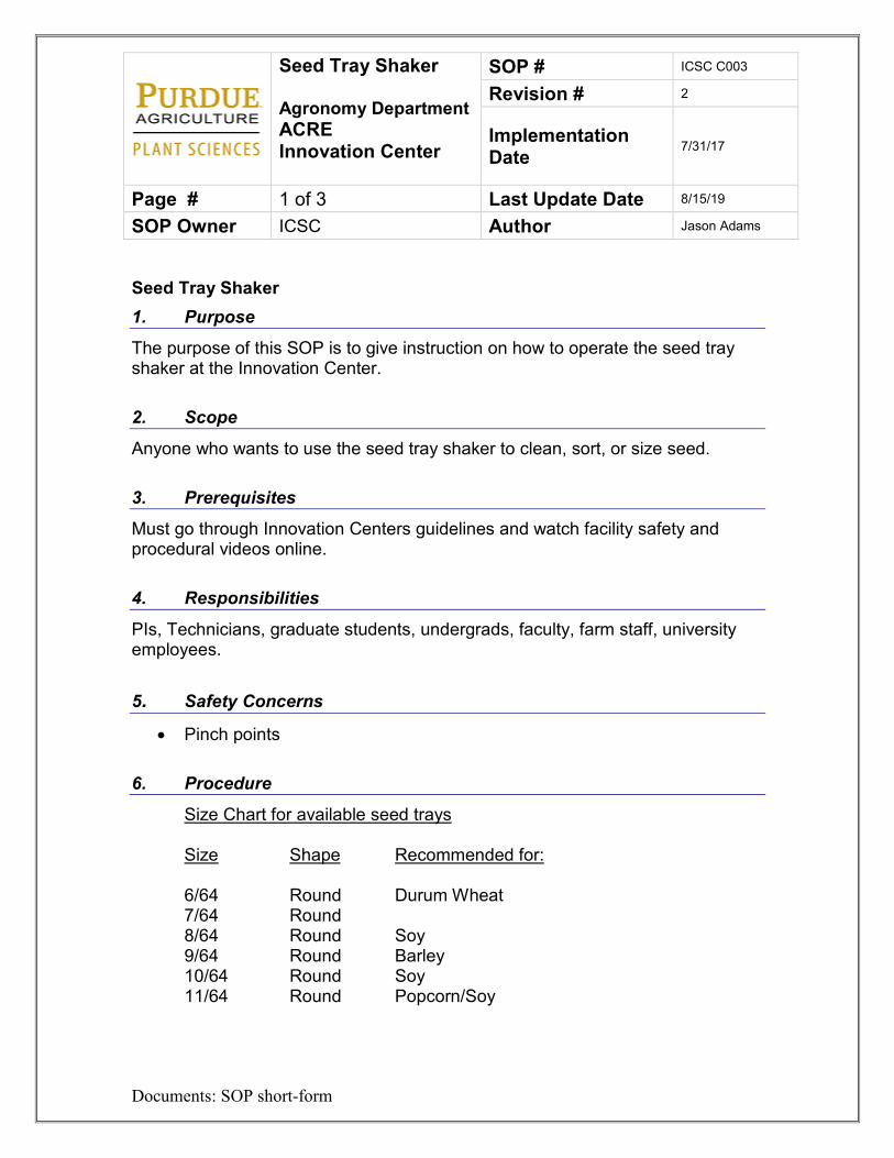
Seed Tray Shaker 1. Purpose
The purpose of this SOP is to give instruction on how to operate the seed tray shaker at the Innovation Center. 2. Scope
Anyone who wants to use the seed tray shaker to clean, sort, or size seed. 3. Prerequisites
Must go through Innovation Centers guidelines and watch facility safety and procedural videos online. 4. Responsibilities
PIs, Technicians, graduate students, undergrads, faculty, farm staff, university employees.
5. Safety Concerns • Pinch points
6. Procedure
Size Chart for available seed trays Size Shape Recommended for: 6/64 Round Durum Wheat 7/64 Round 8/64 Round Soy 9/64 Round Barley 10/64 Round Soy 11/64 Round Popcorn/Soy
Seed Tray Shaker Agronomy Department ACRE Innovation Center
SOP # ICSC C003
Revision # 2
Implementation Date 7/31/17
Page # 2 of 3 Last Update Date 8/15/19
SOP Owner ICSC Author Jason Adams
Documents: SOP short-form
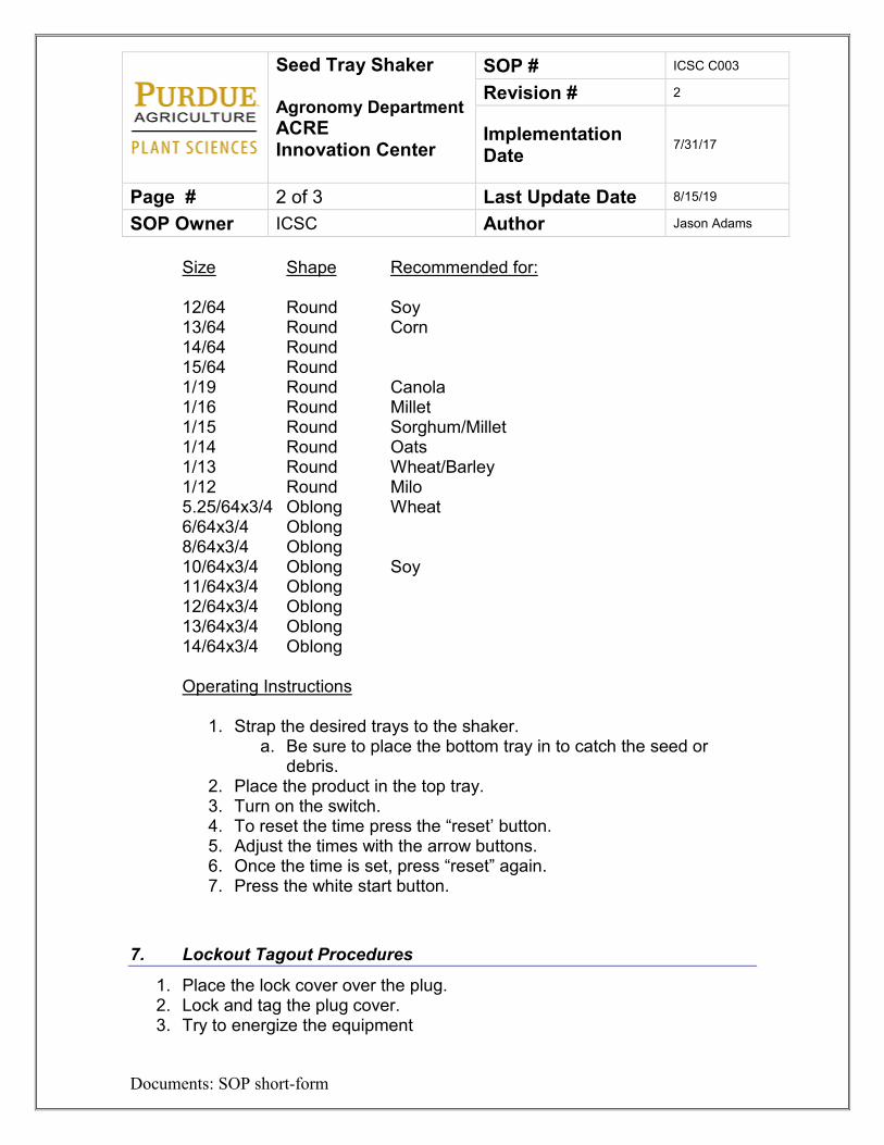
Size Shape Recommended for: 12/64 Round Soy 13/64 Round Corn 14/64 Round 15/64 Round 1/19 Round Canola 1/16 Round Millet 1/15 Round Sorghum/Millet 1/14 Round Oats 1/13 Round Wheat/Barley 1/12 Round Milo 5.25/64x3/4 Oblong Wheat 6/64x3/4 Oblong 8/64x3/4 Oblong 10/64x3/4 Oblong Soy 11/64x3/4 Oblong 12/64x3/4 Oblong 13/64x3/4 Oblong 14/64x3/4 Oblong Operating Instructions
1. Strap the desired trays to the shaker. a. Be sure to place the bottom tray in to catch the seed or
debris. 2. Place the product in the top tray. 3. Turn on the switch. 4. To reset the time press the “reset’ button. 5. Adjust the times with the arrow buttons. 6. Once the time is set, press “reset” again. 7. Press the white start button.
7. Lockout Tagout Procedures
1. Place the lock cover over the plug. 2. Lock and tag the plug cover. 3. Try to energize the equipment
Seed Tray Shaker Agronomy Department ACRE Innovation Center
SOP # ICSC C003
Revision # 2
Implementation Date 7/31/17
Page # 3 of 3 Last Update Date 8/15/19
SOP Owner ICSC Author Jason Adams
Documents: SOP short-form
4. Perform maintenance. 5. Remove lock and tag.
8. References
Please see Innovation Centers manager for assistance or access to the owner’s manual 9. Definitions
PI – Principal Investigator SOP – Standard Operating Procedure
Almaco Seed Bed Cleaner Agronomy Department ACRE Innovation Center
SOP # ICSC C004
Revision # 3
Implementation Date 5/4/17
Page # 1 of 3 Last Update Date 8/16/19
SOP Owner ICSC Author Jason Adams
Documents: SOP short-form
Standard Operating Procedure – Almaco Seed Bed Cleaner 1. Purpose
The purpose of this SOP is to give instruction on how to operate the Almaco Seed Bed Cleaner at the Innovation Center. 2. Scope
Anyone who may need to clean seed in the Threshing and Shelling Room. 3. Prerequisites
Must go through Innovation Center guidelines and watch facility safety and procedural videos online. Must be set up in iLabs. 4. Responsibilities
PIs, Technicians, grad students, undergrads, University employees, faculty, farm staff. 5. Safety Concerns
• Pinch points • Hearing protection • Eye protection
6. Procedure
For cleaning grain coming off the Maizer:
1. Reserve the cleaner in iLabs. Refer to SOP F001. 2. Obtain the correct screens.
Almaco Seed Bed Cleaner Agronomy Department ACRE Innovation Center
SOP # ICSC C004
Revision # 3
Implementation Date 5/4/17
Page # 2 of 3 Last Update Date 8/16/19
SOP Owner ICSC Author Jason Adams
Documents: SOP short-form
a. To change the screens remove the side panels with the Allen wrench, wrenches are located in magnetic tray on cleaner.
b. Remove the screens. c. Add the desired screens. d. Replace the side panels.
3. Place bins to catch the grain under the side and end chute. 4. Turn on the main trunk line and dust collectors “A” and “B” see SOP
TS001. 5. Turn on the cleaner. 6. After the seed is shelled in the Maizer transfer the seed to the aspirator by
moving the lever switch to transfer. 7. After the seed is transferred empty the seed to the cleaner by moving the
lever to “dump”. 8. Adjust gate to control the speed of the grain. Many times the cleaner
works better if there is a substantial amount of grain moving over the screens.
9. Clean seed will dump out the side. Debris and odd sized seed will dump out the end.
10. Be sure to clean the screens between the samples. 11. Turn off the machine after you are done and clean up any spills.
Cleaning Bulk Seed
1. Obtain the correct screens. a. To change the screens remove the side panels with the Allen
wrench, wrenches are located in magnetic tray on cleaner. b. Remove the screens. c. Add the desired screens. d. Replace the side panels.
2. Place bins to catch the grain under the side and end chute. 3. Turn on the main trunk line and dust collectors “A” and “B” see SOP
TS001. 4. Turn on the cleaner 5. Poor the seed at the upper end of the cleaner or transfer the seed from
either the Maizer of through a vacuum tube located in the cabinets in room 1124.
Almaco Seed Bed Cleaner Agronomy Department ACRE Innovation Center
SOP # ICSC C004
Revision # 3
Implementation Date 5/4/17
Page # 3 of 3 Last Update Date 8/16/19
SOP Owner ICSC Author Jason Adams
Documents: SOP short-form
6. Adjust gate to control the speed of the grain. Many times the cleaner works better if there is a substantial amount of grain moving over the screens.
7. Clean seed will dump out the side. Debris and odd sized seed will dump out the end.
8. Be sure to clean the screens between the samples. 9. Turn off the machine after you are done and clean up any spills.
7. Lockout Tag out Procedures
1. Remove the plug form the outlet. 2. Place a plug cover over the plug. 3. Place the appropriate lock and tag on the plug cover. 4. Place a lock and tag on the air transfer toggle. 5. Try to start the seed bed cleaner to see if it is energized. 6. Perform maintenance. 7. Remove the lock on the air toggle. 8. Remove the lock on the plug cover
8. References
Please see Innovation Center manager for instructions or owner’s manual. 9. Definitions
ACRE – Agronomy Center for Research and Education Almaco Seed Bed Cleaner – This is the piece of equipment in the Threshing and
shelling room that is used to clean seed LOTO – Lockout Tag out. The act of locking a machine or device so it may not be
energized during maintenance PI – Principal Investigator SOP – Standard Operating Procedure
Agriculex Seed Counter Agronomy Department ACRE Innovation Center
SOP # ICSC CT001
Revision # 2
Implementation Date 8/2/17
Page # 1 of 7 Last Update Date 8/20/19
SOP Owner ICSC Author Jason Adams
Documents: SOP short-form
Standard Operating Procedure – Agriculex Seed Counter 1. Purpose
The purpose of this SOP is to give instruction on how to operate the Agriculex Seed Counter at the Innovation Center. 2. Scope
Anyone who may need to count seeds coming off any of the equipment in the threshing and shelling room. 3. Prerequisites Must go through Innovation Center guidelines and watch facility safety and procedural videos online. Must be set up in iLabs. 4. Responsibilities
PIs, Technicians, graduate students, undergrads, University employees, faculty, farm staff. 5. Safety Concerns
• Pinch points • Hearing protection
6. Procedure
Basic Operation of Counting
1. Reserve the counter in iLabs. Refer to F001. 2. You will start by attaching the seed counter to the equipment. 3. Replace the seed collection funnel on the counter with the one currently
on the machine. This may take assistance from the facility manager.
Agriculex Seed Counter Agronomy Department ACRE Innovation Center
SOP # ICSC CT001
Revision # 2
Implementation Date 8/2/17
Page # 2 of 7 Last Update Date 8/20/19
SOP Owner ICSC Author Jason Adams
Documents: SOP short-form
4. Attach the air supply line from the overhead air reels in the Threshing and Shelling room to the seed counter.
5. Turn on the seed counter and let it boot up. 6. You may need to navigate to the main menu with the arrow keys.
Totalize Mode
1. To run totalize mode press “1” on the main menu. 2. Run the sample through the thresher or sheller. 3. Hit the up arrow button to transfer the seed.
a. You may need to adjust the airflow on the black knob near the funnel. If you are losing too much seed in the collection bag then the airflow needs turned down. If the air is not delivering the seed to the counter then you need to turn the air up.
4. The total seed count will be displayed on the screen a. Be sure to check the first few samples and adjust the sensitivity on
the black dial on the counter. 5. Place an envelope or tray under the forward silver shoot to collect the
seed. To count and cut seed
1. Navigate to the main menu.. 2. Press “2” to count and cut 3. You have the opportunity to enter a number to discard before the seed
goes through the counter. a. Enter a number then press ok.
4. Then enter the number of seeds in the sample then press ok. 5. Run the sample through the thresher or sheller. 6. Press the up arrow to deliver the seed to the counter.
a. You may need to adjust the airflow on the black knob near the funnel. If you are losing too much seed in the collection bag then the airflow needs turned down. If the air is not delivering the seed to the counter then you need to turn the air up.
7. The total seed count, initial discard, and the seed count will be displayed on the monitor.
a. Be sure to check the first few samples and adjust the sensitivity on the black dial.
Agriculex Seed Counter Agronomy Department ACRE Innovation Center
SOP # ICSC CT001
Revision # 2
Implementation Date 8/2/17
Page # 3 of 7 Last Update Date 8/20/19
SOP Owner ICSC Author Jason Adams
Documents: SOP short-form
8. Be sure to place a packet or container under the discard or back silver shoot.
9. Then when you place a packet under the forward shoot it will discard the counted seeds in the front and the discarded seeds in the back.
7. Lockout Tag out Procedure
1. Remove the plug from the power. 2. Place a plug cover over the plug. 3. Place the proper lock and tag on the cover. 4. Try to energize the sheller. 5. Perform maintenance. 6. Remove lock and tag.
8. References
Please see Innovation Center manager for instructions or owner’s manual. 9. Definitions
ACRE – Agronomy Center for Research and Education Agriculex Single Ear Corn Sheller – This is the piece of equipment in the
Threshing and shelling room that is used to shell single ears
LOTO – Lockout Tag out. The act of locking a machine or device so it may not be energized during maintenance
PI – Principal Investigator SOP – Standard Operating Procedure Attachment 1
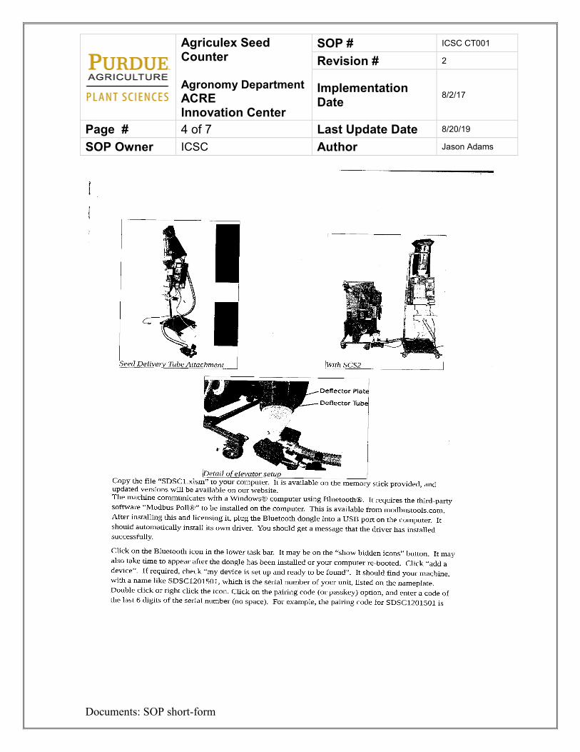
Agriculex Seed Counter Agronomy Department ACRE Innovation Center
SOP # ICSC CT001
Revision # 2
Implementation Date 8/2/17
Page # 4 of 7 Last Update Date 8/20/19
SOP Owner ICSC Author Jason Adams
Documents: SOP short-form
Agriculex Seed Counter Agronomy Department ACRE Innovation Center
SOP # ICSC CT001
Revision # 2
Implementation Date 8/2/17
Page # 5 of 7 Last Update Date 8/20/19
SOP Owner ICSC Author Jason Adams
Documents: SOP short-form
Agriculex Seed Counter Agronomy Department ACRE Innovation Center
SOP # ICSC CT001
Revision # 2
Implementation Date 8/2/17
Page # 6 of 7 Last Update Date 8/20/19
SOP Owner ICSC Author Jason Adams
Documents: SOP short-form
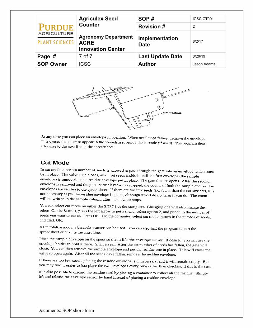
Agriculex Seed Counter Agronomy Department ACRE Innovation Center
SOP # ICSC CT001
Revision # 2
Implementation Date 8/2/17
Page # 7 of 7 Last Update Date 8/20/19
SOP Owner ICSC Author Jason Adams
Documents: SOP short-form
Color Sorter Agronomy Department ACRE Innovation Center
SOP # ICSC CT002
Revision # 1
Implementation Date 7/18/17
Page # 1 of 3 Last Update Date 7/30/18
SOP Owner ICSC Author Jason Adams
Documents: SOP short-form
Standard Operating Procedure – Color Sorter 1. Purpose
The purpose of this SOP is to give instruction on how to operate the Color/Shape Sorter and seed counter at the Innovation Center. 2. Scope
Anyone who may need to sort seed by color, shape or count seed in the Innovation Center. 3. Prerequisites Must go through Innovation Center guidelines and watch facility safety and procedural videos online. It is recommended to get hands on training with this machine. Must be set up in iLabs. 4. Responsibilities
PIs, Technicians, graduate students, undergrads, University employees, faculty, farm staff. 5. Safety Concerns
• Hearing protection is required if the VMek is placed in the Threshing and
Shelling Room
6. Procedure
1. Reserve the instrument in iLabs. Refer to SOP F001. 2. Turn on the computer by pressing the blue button on the left side of the
counter. a. The Counter will automatically load in the program that does not
deal with soybean hilum sorting.
Color Sorter Agronomy Department ACRE Innovation Center
SOP # ICSC CT002
Revision # 1
Implementation Date 7/18/17
Page # 2 of 3 Last Update Date 7/30/18
SOP Owner ICSC Author Jason Adams
Documents: SOP short-form
3. If the software does not initialize automatically. Then hit the INIT button on the bottom right then wait for it to initialize.
4. Either load a “Recipe” in the drop down menu or create a new one. For Counting:
1. Load in Ejector Test in the recipe drop down. 2. Press on to turn the lights on in the lower right. 3. Make sure there is a bin set under both the discharge and ejection chutes. 4. Make sure the gate is down inside the hopper. 5. Place the seed in the hopper. 6. Press start on the bottom right side of the screen. 7. The machine will count and display the number on the top of the screen. 8. If you want information about the seed that passed you can go to the
Analytics tab and hit populate. a. This will give you data regarding the seed that passes and the
information may be saved or downloaded. 9. Before you repeat the steps be sure to clear the data from the previous
count by pressing clear data at the bottom of the screen on the recipe tab. For sorting: This process is the same regardless of whether are sorting for color or for shape.
1. Open the classifier tab. 2. Define the classifier names by clicking on the cell and naming them. I.e.
good…bad or orange…yellow. a. You may add classifiers up to five but the lower the number the
better. To do this press the Add New button. 3. Press setup. This will add a tab with each name. 4. Select the desired tab then press on to turn on the lights. 5. Press the capture on button the drop representative sample that you want
to use for the bulk of the sample. This sample will not be ejected. 6. Press capture off. 7. Select add radio button to the desired channel.
a. Adjust the Min/Max sliders to isolate the desired colors i. This step will take some adjusting and trial and error on the
user’s part. 8. Repeat the above steps for each tab.
Color Sorter Agronomy Department ACRE Innovation Center
SOP # ICSC CT002
Revision # 1
Implementation Date 7/18/17
Page # 3 of 3 Last Update Date 7/30/18
SOP Owner ICSC Author Jason Adams
Documents: SOP short-form
9. After the parameters have been set you then load the recipe and run the samples as listed above.
7. Lockout Tagout Procedures
1. Turn off the machine. 2. Turn large Red switch on the right of the machine to the off position. 3. Place the appropriate lock and tag on the sorter. 4. Try to energize the machine. 5. After maintenance is complete then remove the lock and tag. 6. Turn the red switch back on.
8. References
Please watch the instructional video or see Innovation Center manager for instructions or owner’s manual. 9. Definitions
ACRE – Agronomy Center for Research and Education LOTO – Lockout Tagout. The act of locking a machine or device so it may not be
energized during maintenance PI – Principal Investigator SOP – Standard Operating Procedure
Packet Seed Counter Agronomy Department ACRE Innovation Center
SOP # ICSC CT003
Revision # 2
Implementation Date 10/5/16
Page # 1 of 5 Last Update Date 8/26/19
SOP Owner ICSC Author Jason Adams
Documents: SOP short-form
Standard Operating Procedure – Packet Seed Counter 1. Purpose
The purpose of this SOP is to give instruction on how to operate the Packet Seed Counters at the Innovation Center. 2. Scope
Anyone who may need to count seed in the Innovation Center. 3. Prerequisites Must go through Innovation Center guidelines and watch facility safety and procedural videos online. Must be set up in iLabs. 4. Responsibilities
PIs, Technicians, grad students, undergrads, University employees, faculty, farm staff. 5. Safety Concerns
• none
6. Procedure
***First choose the desired seed counter. We have five that count and package and one that counts and weighs. The counter with the scale underneath is the one that weights***. The Packaging Counter
Packet Seed Counter Agronomy Department ACRE Innovation Center
SOP # ICSC CT003
Revision # 2
Implementation Date 10/5/16
Page # 2 of 5 Last Update Date 8/26/19
SOP Owner ICSC Author Jason Adams
Documents: SOP short-form
This counter maybe used to count the total lot of seed or count a desired amount and place in a package. To Totalize:
1. Reserve the Counter in iLabs. Refer to SOP F001. 2. Turn on the counter.
a. Place the “Count/Hold” switch to hold. b. Turn the feeder switch to off.
3. Place the seed in the upper bowl. 4. A bag will need to be placed at the bulk discharge as well as the packet
discharges. 5. With the arrow pointing at Totalize, press set. 6. Flip the “Count/Hold” Switch as well as the feeder switch.
a. If at any time you want to pause the counter just flip to Hold. 7. The counter should run and count the entire lot. 8. Adjust the speed as needed. 9. Adjust the ribbons on the bowl to line up the seed in a single file, single
layered fashion. To count and package
1. Reserve the Counter in iLabs. Refer to SOP F001. 2. Turn on the counter.
a. Place the “Count/Hold” switch to hold. b. Turn the feeder switch to off.
3. Place the seed in the bowl. 4. A bag will need to be placed at the bulk discharge as well as the packet
discharges. 5. Press next to place the arrow to lot size then press set. 6. Enter number of lots you want to run. If you are not sure just put in a large
number then press next. 7. Enter the number of seeds you want per envelope then press set. 8. Then press run. 9. Flip the “Count/Hold” Switch to count. Then flip the Feeder “on/off” switch
to on. 10. The seed will be counted into the packet with the green light…When that
packet reaches the desired seed count it will automatically switch to the next packet.
Packet Seed Counter Agronomy Department ACRE Innovation Center
SOP # ICSC CT003
Revision # 2
Implementation Date 10/5/16
Page # 3 of 5 Last Update Date 8/26/19
SOP Owner ICSC Author Jason Adams
Documents: SOP short-form
11. Remove the first packet and replace it with an empty one. 12. The counter will cycle back and forth between packets until done. 13. Adjust the speed as needed and the ribbons on the bowl to align up the
seed. 14. If at any time you need to pause just flip the switch to Hold. 15. At any time you can return to the main menu by pressing mode. 16. When you are done you can empty the seed bowl by dumping it into the
silver chute then into your discard bag. The Weighing Counter This counter maybe used to count the total lot of seed or count a desired amount and weigh the sample. To Totalize and weigh:
1. Reserve the Counter in iLabs. Refer to SOP F001. 2. Turn on the scale and zero.
a. Note: If at any time you are running this counter and you receive an error. Most of the time it is due to the scale not being at zero. Press zero on the scale and reset on the counter to clear the error.
3. Turn on the counter. a. Place the “Count/Hold” switch to hold. b. Turn the feeder switch to off.
4. Place the seed in the upper bowl. 5. Press menu to get to the main screen if needed. 6. Press enter at the operation selection. 7. Press reset twice at Totalize…This will count your entire lot. 8. Flip the switch to Count. 9. Adjust the speed dials and ribbons on the bowl as needed to get the
correct flow coming out of the bowl. 10. At any time you may place the switch to hold to pause or press menu to
go back to the beginning.
To Count and weigh:
1. Turn on the scale and zero.
Packet Seed Counter Agronomy Department ACRE Innovation Center
SOP # ICSC CT003
Revision # 2
Implementation Date 10/5/16
Page # 4 of 5 Last Update Date 8/26/19
SOP Owner ICSC Author Jason Adams
Documents: SOP short-form
a. Note: If at any time you are running this counter and you receive an error. Most of the time it is due to the scale not be at zero. Press zero on the scale and reset on the counter to clear the error.
2. Turn on the counter. a. Place the “Count/Hold” switch to hold. b. Turn the feeder switch to off.
3. Place the seed in the upper bowl. 4. Press menu to get to the main screen if needed. 5. Press enter at the Operation selection. 6. Press next to advance to the Default # of seeds selection. 7. Press enter. 8. Press enter to change the number of seeds to count. 9. Type in the number you want counted and press enter. 10. Press reset twice and flip the switch to count. 11. Adjust the speed and ribbons on the bowl to desired speed. 12. Once the sample is counted, record your weight. 13. When finished empty the bowl by tilting it to the right and collecting it in a
container. 7. Lockout Tagout Procedures
1. Unplug the machine. 2. Place a plug cover over the lock. 3. Lock and tag the plug cover. 4. Try to energize the counter. 5. Perform maintenance. 6. Remove the lock and tag.
8. References
Please watch the instructional video or see innovation Center manager for instructions or owner’s manual.

Packet Seed Counter Agronomy Department ACRE Innovation Center
SOP # ICSC CT003
Revision # 2
Implementation Date 10/5/16
Page # 5 of 5 Last Update Date 8/26/19
SOP Owner ICSC Author Jason Adams
Documents: SOP short-form
9. Definitions
ACRE – Agronomy Center for Research and Education. LOTO – Lockout Tagout. The act of locking a machine or device so it may not be
energized during maintenance. PI – Principal Investigator. Seed Counter – A piece of equipment used for counting seed. SOP – Standard Operating Procedure.
Seed Treater Agronomy Department ACRE Innovation Center
SOP # ICSC CT004
Revision # 3
Implementation Date 9/22/16
Page # 1 of 3 Last Update Date 8/27/19
SOP Owner ICSC Author Jason Adams
Documents: SOP short-form
Standard Operating Procedure – Seed Treater 1. Purpose
The purpose of this SOP is to give instruction on how to operate the Seed Treaters at the Innovation Center. 2. Scope
Anyone who may need to treat seed in the Innovation Center. 3. Prerequisites Must go through Innovation Center guidelines and watch facility safety and procedural videos online. Also, must have gone through Purdue WPS training if using any type of regulated chemical in the treater. You will also need to be set up in Purdue iLabs to reserve and turn on the seed treaters. 4. Responsibilities
PIs, Technicians, grad students, undergrads, University employees, faculty, farm staff. 5. Safety Concerns
• Inhalation • Dermal • Chemical exposure • Pinch points • ALWAYS WEAR THE APPROPRIATE PPE AS SUGGESTED BY THE
CHEMICAL LABEL. Since there are two seed treaters in the small room. You will also want to consider the PPE requirements on the seed treatment being used on the adjoining seed treater.
Seed Treater Agronomy Department ACRE Innovation Center
SOP # ICSC CT004
Revision # 3
Implementation Date 9/22/16
Page # 2 of 3 Last Update Date 8/27/19
SOP Owner ICSC Author Jason Adams
Documents: SOP short-form
6. Procedure
1. Reserve the seed treaters in iLabs. See SOP F001. 2. Bring in the appropriate seed treatment.
a. It is the user’s responsibility to bring in their own seed treatment. The seed treatment must be in a sturdy container (preferably the original labeled container). Or a properly labeled secondary container. The facility manager has secondary labels if needed.
b. A lab mixer is part of the seed treating equipment. You may consider putting in a mixing bar in your container to aid in agitation.
c. An SDS sheet must be presented to the facility manager before seed treatment begins.
3. Place the labeled chemical container on the agitator. 4. Turn on the power to the equipment by flipping the switch on the wall near
the door. It is the switch with the little red light. 5. Turn on the agitator. 6. Turn on the power to the treater. 7. On the Touch screen, F1 will take you to the “Home Screen”. F2 will take
you to the “Adjustments Screen.” 8. Press F2 9. Adjust your pump time, coat time and door open time accordingly.
a. The pump time is the amount of time that seed treatment is delivered to the mixing drum.
b. Coat time is how long the seed rotates in the drum. c. Door open time is how long the door stays open.
10. You may make adjustments anytime to these settings to get the proper seed coat in the most efficient way. In the end, all your seed should be properly covered without excessive seed treatment. If at any time you have seed treatment coming out of the spout you are putting too much treatment on.
11. Press F1 to return to the “Home Screen”. 12. Turn on the Rotor 13. Turn on the Atom. 14. Adjust the drum speed at any time as needed. 15. Dump the seed into the upper chamber. 16. Press the foot pedal. 17. Place package under the exit spout. If this is not done seed will spill onto
the floor.
Seed Treater Agronomy Department ACRE Innovation Center
SOP # ICSC CT004
Revision # 3
Implementation Date 9/22/16
Page # 3 of 3 Last Update Date 8/27/19
SOP Owner ICSC Author Jason Adams
Documents: SOP short-form
18. Repeat. Clean up
1. Clean up all equipment at the completion of the task or at the end of the day.
2. You may either follow the cleanup directions on the drum or you may use the cleaning supplies on site to clean up the equipment.
3. Be sure to pump fresh water through the lines. 7. Lockout Tagout Procedures
1. To lock out the equipment unplug the machine and place a cord cover over the outlet.
2. Attach a lock and label. 3. Try to energize the equipment. 4. Perform maintenance. 5. Remove lock and tag.
8. References
Please watch the instructional video or see Innovation Center manager for instructions or owner’s manual. 9. Definitions
ACRE – Agronomy Center for Research and Education LOTO – Lockout Tagout PI – Principal Investigator PPE – Personal Protective Equipment SDS – Safety Data Sheet Seed Counter – A piece of equipment used for counting seed SOP – Standard Operating Procedure WPS – Worker Protection Standards. This training gives you vital safety
information in regards to agricultural pesticide usage at the ACRE farm campus.
Large Seed and Plant Grinders Agronomy Department ACRE Innovation Center
SOP # ICSC G001
Revision # 3
Implementation Date 5/4/17
Page # 1 of 4 Last Update Date 8/27/19
SOP Owner ICSC Author Jason Adams
Documents: SOP short-form
Standard Operating Procedure – Seed and Plant Grinders 1. Purpose
The purpose of this SOP is to give instruction on how to operate the large seed and plant grinders at the Innovation Center. 2. Scope
Anyone who may need to grind small lots of seed and plant material in the Innovation Center. 3. Prerequisites Must go through Innovation Center guidelines and watch facility safety and procedural videos online. Must be set up in iLabs to reserve and turn on the grinders. 4. Responsibilities
PIs, Technicians, grad students, undergrads, University employees, faculty, farm staff. 5. Safety Concerns
• Pinch points • Noise
6. Procedure
Operation
1. Reserve and turn on the grinders in iLab. Refer to SOP F001. 2. Turn on the power. 3. Always start the mill before adding the samples.
Large Seed and Plant Grinders Agronomy Department ACRE Innovation Center
SOP # ICSC G001
Revision # 3
Implementation Date 5/4/17
Page # 2 of 4 Last Update Date 8/27/19
SOP Owner ICSC Author Jason Adams
Documents: SOP short-form
4. Rotation begins by turning on the green button and selecting one of the three run modes that will be described later.
5. Rotation ends by pressing the red stop button. 6. Desired speeds are achieved by pressing the up down arrows on the
keypad. 7. Materials that do not flow free may need to be forced in the chamber with
the plunger. a. For optimum results feed material slowly to the approximate rate of
ground material being delivered. b. Do not overload the chamber.
8. Hard or tough material should be reduced to a smaller size before feeding into the mill.
a. If jamming occurs stop the mill immediately with the red button. b. Open the door and remove the jamming particles. c. A safety interlock prevents operation of the mill with the chamber
door open. 9. After each sample is finished, clean the chamber per your labs
requirements. NEVER SPRAY CLEANING SOLUTION IN THE BACK OF THE CHAMBER. This cuases solution and dust to collect behind the drum causing the drum to be jammed up and contaminated.
Run Mode:
1. Move the cursers using the up/down feature and select Run Mode. a. The speed shown in parenthesis (xxx) is the set speed and is
controlled by the user. b. The speed on the right is the tachometer readout or actual speed.
2. The cursor can be moved with the up and down arrows. 3. Move the cursor to the RPM line item and press enter. 4. The speed can now be increased or decreased pressing and holding the
up/down arrows. 5. Press the enter button once more to move the cursor again. 6. To pause the mill move the cursor to the Pause and press the enter
button. 7. To resume select resume and press the enter button. 8. To go back to the main menu move the cursor to the Exit item and then
press the enter button. Timed Run Mode:
Large Seed and Plant Grinders Agronomy Department ACRE Innovation Center
SOP # ICSC G001
Revision # 3
Implementation Date 5/4/17
Page # 3 of 4 Last Update Date 8/27/19
SOP Owner ICSC Author Jason Adams
Documents: SOP short-form
1. Move the cursor using the up/down feature and select Timed Run Mode. 2. The up/down arrows can be used to move the Cursor between
parameters. 3. Press the enter button to adjust setting. 4. Now the up/down arrows can be used to change the parameters values. 5. Press the enter button once more to move the Cursor again. 6. Once the time is set move the Cursor to the RPM line item. 7. Press the enter Button. 8. The speed can be set using the up/down arrows. 9. Press the Enter Button once more to move the Cursor again. 10. Now that the data is set navigate the Cursor to the START line item and
press the Enter Button. 11. After selecting START the mill will begin at the selected speed and the
timer will begin counting down. 12. The speed can be adjusted in real time using the same procedure as
outlined in Run Menu section. 13. The mill and countdown timer can be paused and resumed.
Speed Run Mode:
1. Move the cursor using the up/down feature and select Speed Run Mode. 2. Select the Speed Run Mode from the menu and press Enter Button.. 3. You will be prompted to with the Speed Run Mode Setup Menu 4. Navigate the Cursor to the RPM line item and press Enter Button. 5. Adjust the speed with the up/down arrows. 6. Press the Enter Button. 7. Move the cursor between Start and Exit. 8. Exit will take the cursor back to the main menu. 9. Keep the Cursor next to the Start line item and press the Enter Button. 10. You will now be taken to the Speed Run Menu The mill will begin at the
speed selected.
Large Seed and Plant Grinders Agronomy Department ACRE Innovation Center
SOP # ICSC G001
Revision # 3
Implementation Date 5/4/17
Page # 4 of 4 Last Update Date 8/27/19
SOP Owner ICSC Author Jason Adams
Documents: SOP short-form
7. Lockout Tag out
1. Turn off the grinder. 2. Unplug the grinder. 3. Place plug cover LOTO device over the plug. 4. Lock and tag the plug cover. 5. Try to energize the grinder by turning it on. 6. Perform maintenance. 7. Remove the lock and cover. 8. Plug grinder back in.
8. References
Please watch the instructional video or see Innovation Center manager for instructions or owner’s manual. 9. Definitions
ACRE – Agronomy Center for Research and Education LOTO – Lockout Tag out. The act of locking a machine or device so it may not be
energized during maintenance PI – Principal Investigator SOP – Standard Operating Procedure
UDY Grinder Agronomy Department ACRE Innovation Center
SOP # ICSC G002
Revision # 2
Implementation Date 8/27/19
Page # 1 of 2 Last Update Date 7/30/18
SOP Owner ICSC Author Jason Adams
Documents: SOP short-form
Standard Operating Procedure – UDY Grinder 1. Purpose
The purpose of this SOP is to give instruction on how to operate the UDY Grinders at the Innovation Center. 2. Scope
Anyone who may need to grind small lots of seed and plant material in the Innovation Center. 3. Prerequisites
Must go through Innovation Center guidelines and watch facility safety and procedural videos online. You must also be set up in iLabs to reserve the grinder. 4. Responsibilities
PIs, Technicians, grad students, faculty, farm staff. 5. Safety Concerns
• Pinch points • Noise • Dust
6. Procedure
1. Reserve the grinder using iLabs. Refer to SOP F001. 2. Choose the proper size screen and place it in the slot in the grinder chamber. 3. Choose the desired grinder cover. 4. Make sure cone shaped filter is in the grinder cover. 5. Latch down the grinder cover. 6. Place glass or plastic container under the discharge chute. 7. Turn on the grinder.
UDY Grinder Agronomy Department ACRE Innovation Center
SOP # ICSC G002
Revision # 2
Implementation Date 8/27/19
Page # 2 of 2 Last Update Date 7/30/18
SOP Owner ICSC Author Jason Adams
Documents: SOP short-form
8. Insert material into the grinder through the cover. 9. When Grinding is complete, turn the switch off. 10. Clean the grinder.
7. Lockout Tag out
1. Turn off the grinder. 2. Unplug the grinder. 3. Place plug cover LOTO device over the plug. 4. Lock and tag the plug cover. 5. Try to energize the grinder by turning it on. 6. Perform maintenance. 7. Remove the lock and cover. 8. Plug grinder back in.
8. References
Please watch the instructional video or see Innovation Center manager for instructions or owner’s manual. 9. Definitions
ACRE – Agronomy Center for Research and Education LOTO – Lockout Tag out. The act of locking a machine or device so it may not be
energized during maintenance PI – Principal Investigator SOP – Standard Operating Procedure
Scales Agronomy Department ACRE Innovation Center
SOP # ICSC M001
Revision # 2
Implementation Date 5/8/17
Page # 1 of 2 Last Update Date 8/27/19
SOP Owner ICSC Author Jason Adams
Documents: SOP short-form
Standard Operating Procedure – Scales 1. Purpose
The purpose of this SOP is to give instruction on how to operate the scales at the Innovation Center. 2. Scope
Anyone who may need to weigh seed in the Innovation Center. 3. Prerequisites Must go through Innovation Center guidelines and watch facility safety and procedural videos online. 4. Responsibilities
PIs, Technicians, grad students, undergrads, University employees, faculty, farm staff. 5. Safety Concerns
• none
6. Procedure
Table Top Scales: Either 2200g max weight or 10,000, max weight
1. Retrieve desired scale from cabinets in Plant and Seed Processing room.
a. Scales may be moved throughout the building but not removed from the b.uilding.
2. Turn scale on 3. Zero or tare scale.
Scales Agronomy Department ACRE Innovation Center
SOP # ICSC M001
Revision # 2
Implementation Date 5/8/17
Page # 2 of 2 Last Update Date 8/27/19
SOP Owner ICSC Author Jason Adams
Documents: SOP short-form
4. If scale does not seem to be working properly then turn scale over to see if it is in lock mode.
5. Scales may be hooked up to PC with connecting cables located in the drawers near where the scales are stored.
6. Scales must not leave the ICSC facility. 7. Return scales back to shelves when finished.
Floor Scale: 250lb max
1. Turn on the scale. 2. Zero or tare the scale. 3. Place material to be weighed on the platform . 4. Turn off the scale when you are done.
7. Lockout Tagout Procedures
1. Unplug the machine. 2. Place a plug cover over the lock. 3. Lock and tag the plug cover. 4. Try to energize the scale. 5. Perform maintenance. 6. Remove the lock and tag.
8. References
Please watch the instructional video or see Innovation Center Facility manager for instructions or owner’s manual. 9. Definitions
ACRE – Agronomy Center for Research and Education PI – Principal Investigator SOP – Standard Operating Procedure
PhenoRover Agronomy Department ACRE Innovation Center
SOP # ICSC M002
Revision # 3
Implementation Date 5/10/17
Page # 1 of 6
Last Reviewed/Update Date
8/27/19
SOP Owner ICSC Author Jason Adams/Andy Linvill
Documents: SOP short-form
Standard Operating Procedure – PhenoRover 1. Purpose
The purpose of this SOP is to give instruction on how to operate the PhenoRover at the Innovation Center. 2. Scope
Anyone who may need to operate the PhenoRover at the Innovation Center or ACRE campus. 3. Prerequisites Must go through Innovation Center guidelines and watch facility safety videos. As well as hands on training by Innovation Center facility manager or designee. 4. Responsibilities
PIs, Technicians, grad students, University employees, faculty, farm staff. 5. Safety Concerns
• Falls • Rollovers • Pinch points • Burns • Electrical shock • Hydraulic Pressure
6. Procedure
PhenoRover Agronomy Department ACRE Innovation Center
SOP # ICSC M002
Revision # 3
Implementation Date 5/10/17
Page # 2 of 6
Last Reviewed/Update Date
8/27/19
SOP Owner ICSC Author Jason Adams/Andy Linvill
Documents: SOP short-form
Prestart
1. Refer to operator’s manual for complete details. 2. Check tire inflation (60 psi) LF____ RF_____ RR_____ LR_____ and lugnut torque (107
lbs./ft.). 3. Grease center pivot (use only special grease for PhenoRover) 50 hrs. 4. Check for leaks around hoses, engine, fuel tank, hydraulic cylinders, etc. 5. Check Fluids:
a. Engine Oil b. Coolant c. Hydraulic fluid d. Fuel (diesel only) e. Generator fuel and oil
6. Check belt tension on fan/alternator/AC. 7. Check boom pivots and lift cylinders, bolts tight. 8. Check that boom is properly mounted and secured. 9. Check that each sensor is properly attached.
a. Grab each sensor and wiggle each direction. b. Grab each sensor mount and wiggle each direction. c. Check sensor mounting bolts are tight. d. Check electrical connections and cords are clear and have enough movement
for all machine operations. 10. Check that batteries are secured and charged. 11. Check that data cord is detached and removed from the machine. 12. Check that any other cords or battery chargers are unhooked and removed from
machine. 13. Start generator:
a. Turn on the fuel b. Turn the key c. Choke as needed
14. Turn key to first position and check that all warning lights are operational. Wait for glow plug light to extinguish before starting engine.
15. Start engine, check that warnings extinguish properly. 16. Allow engine to warm up for a minute or two at idle before heavy operation. 17. Check that hydraulics and electronics are operational before travelling to field. 18. Raise ladder before leaving building or making sharp left turns. 19. Increase engine speed to ~1/2 throttle when in building.
PhenoRover Agronomy Department ACRE Innovation Center
SOP # ICSC M002
Revision # 3
Implementation Date 5/10/17
Page # 3 of 6
Last Reviewed/Update Date
8/27/19
SOP Owner ICSC Author Jason Adams/Andy Linvill
Documents: SOP short-form
20. Maintain slow safe speed when maneuvering in or near building. 21. Be aware that moving the steering wheel when machine is not moving forward will
swing the boom to the left and right in an arc that may strike people/objects. 22. Refer to Phenorover operation protocol for field operations. 23. Refer to Phenorover post operation protocol for end of day operations.
Special Notes: • If any questions, please contact Andy Linvill or Jason Adams
Field Operation
1. Refer to Operators Manual for complete details. 2. Refer to Phenorover prestart protocol and checklist before starting. 3. Absolutely no riders on phenorover! 4. At all times check around machine to be clear of people, other equipment or objects
that might damage or be damaged by moving the machine. 5. Be aware that moving the steering wheel when machine is not moving forward will
swing the boom to the left and right in an arc that may strike people/objects. 6. Raise ladder before leaving building and making sharp left turns. 7. Lifting/lowering machine (Manual page 30):
a. Only raise/lower machine on level surface. b. Check overhead clearance before raising machine. c. Set parking brake. d. Increase engine speed to full throttle. e. Use “up/down” switch to raise/lower machine. f. Machine should be in lowered position for transport to and from field. g. Boom should be at its highest limit before raising the chassis of machine to keep
center of gravity as low as possible. 8. Adjusting machine width (Manual page 31):
a. Only change width on level surface, preferably grass or gravel, not pavement or cement.
b. Only change width while driving forward at a safe speed (~3- 10mph). c. Increase engine speed to full throttle. d. Use “in/out” switch to adjust width. e. Machine should be at widest setting for transport to and from field. f. Limit speed when machine is at narrowest setting to prevent tip over.
PhenoRover Agronomy Department ACRE Innovation Center
SOP # ICSC M002
Revision # 3
Implementation Date 5/10/17
Page # 4 of 6
Last Reviewed/Update Date
8/27/19
SOP Owner ICSC Author Jason Adams/Andy Linvill
Documents: SOP short-form
9. If any warning lights come on, cease operation; reduce engine speed as long as safely possible before shutting off. Diagnose and fix problem before resuming operation. If unable to diagnose or fix, contact Andy Linvill or Jason Adams.
10. GPS autosteer operation: a. Turn on Trimble system with button on back of monitor on the top right. b. Select Trimble GPS on right of main desktop screen. Agree to all warnings from
Trimble. c. Touch tractor icon in upper right of start screen. Use the pre-setup Phenorover
settings. d. If field has already been set up, select field from dropdown menu. Select
“enable auto steering”. Select correct line for the field and nursery to be used. Engage auto steer with “steering wheel” icon in lower right corner.
e. Touch “wrench” icon to exit field and open another field or to back out of program to shut down.
f. Touch “shutdown” to shutdown Trimble program. 11. Computer operation:
a. Starting computer. b. Connecting to sensors. c. Infield operation (is machine receiving and recording data). d. Pause recording data? (If we need to stop for a few minutes or on turn
around?). e. Stop recording at end of field before transporting back to buildings.
12. Continuously watch machine for loose or broken parts. Ensure sensor operation and attachment.
13. Keep an eye on the weather. Return to building if threat of rain or lightning. Sensors are not water resistant!
14. Refer to Phenorover Post Operation protocol and checklist for end of day procedures.
Special Notes: • If any questions, please contact Andy Linvill or Jason Adams
Post Operation
1. Refer to operator’s manual for complete details. 2. Before entering building, be sure that machine is in lowered position. 3. Reduce engine speed to ~1/2 throttle when in building. 4. Maintain slow safe speed when maneuvering in or near building.
PhenoRover Agronomy Department ACRE Innovation Center
SOP # ICSC M002
Revision # 3
Implementation Date 5/10/17
Page # 5 of 6
Last Reviewed/Update Date
8/27/19
SOP Owner ICSC Author Jason Adams/Andy Linvill
Documents: SOP short-form
5. Be aware that moving the steering wheel when machine is not moving forward will swing the boom to the left and right in an arc that may strike people/objects.
6. At all times check around machine to be clear of people, other equipment or objects that might damage or be damaged by moving the machine.
7. Allow engine to cool for a few minutes before shutting off. This allows oil to cool the turbocharger to a safe temperature that will prevent damage.
8. Lower boom to lowest position, set parking brake and turn off hydraulic drive system before shutting engine off.
9. GPS Shut down: a. From run screen, touch “wrench” icon to back out of field to start screen. b. Touch “shutdown” icon to shutdown Trimble system.
10. Computer download and shutdown. 11. Turn key to shut off engine. 12. Turn switch on generator to off position then turn valve on fuel cap to off to keep fumes
in tank and prevent them accumulating in building. 13. Walk around machine and inspect for broken/loose pieces, fluid leaks, flat tires, etc.
Notify Andy Linvill or Jason Adams immediately if anything is not right. Do not leave it broken for the next person to fix.
Special Notes:
• If any questions, please contact Jason Adams or Andy Linvill 7. Lockout Tagout Procedures
1. Remove Key from ignition. 2. Remove positive cable from batter and place a plug cover over the cable. 3. Place the appropriate lock and tag over the cable. 4. Try to start the PhenoRover. 5. Perform maintenance. 6. Remove lock and tag.
PhenoRover Agronomy Department ACRE Innovation Center
SOP # ICSC M002
Revision # 3
Implementation Date 5/10/17
Page # 6 of 6
Last Reviewed/Update Date
8/27/19
SOP Owner ICSC Author Jason Adams/Andy Linvill
Documents: SOP short-form
8. References
Please watch the instructional video or see Innovation Center Facility manager for instructions or owner’s manual. 9. Definitions
ACRE – Agronomy Center for Research and Education LOTO – Lockout Tagout PhenoRover – High clearance sprayer chasse equipped with sensors used for
collecting data from the field. PI – Principal Investigator Seed Counter – A piece of equipment used for counting seed SOP – Standard Operating Procedure
Dickey John Agronomy Department ACRE Innovation Center
SOP # ICSC M003
Revision # 2
Implementation Date 8/4/17
Page # 1 of 3 Last Update Date 8/28/19
SOP Owner ICSC Author Jason Adams
Documents: SOP short-form
Standard Operating Procedure – Dickey John Moisture Reader 1. Purpose
The purpose of this SOP is to give instruction on how to operate the Dickey John at the Innovation Center. 2. Scope
Anyone who may need to measure seed moisture at ACRE or ICSC. 3. Prerequisites Must go through Innovation Center guidelines and watch facility safety and procedural videos online. 4. Responsibilities
PIs, Technicians, graduate students, undergrads, University employees, faculty, farm staff. 5. Safety Concerns
• none
6. Procedure
Running the sample
1. Turn on the Dickey John. a. Wait for it to boot up. This make take a minute or two.
2. Select analyze and pick the product that you are sampling. a. The last 4 that have been run through the machine will be
displayed.
Dickey John Agronomy Department ACRE Innovation Center
SOP # ICSC M003
Revision # 2
Implementation Date 8/4/17
Page # 2 of 3 Last Update Date 8/28/19
SOP Owner ICSC Author Jason Adams
Documents: SOP short-form
3. Once you select your product, press the “green” button. 4. Place the product in the hopper. Be sure to add enough to break the beam
at the sensors at the top of the bowl. When you have added enough the light will go form yellow to red.
5. At this screen, you may enter a sample ID and customer ID. Or just press the “green” button through the selections until the sample cycles through.
6. After the sample has run through empty the tray at the bottom the replace the tray.
7. From here you can quit or run the next sample.
Downloading the results
1. Return to the main menu. 2. Press view results.
a. You can download the results from the view results screen. 3. Be sure to place a packet or container under the discard or back silver
shoot. 4. Then when you place packet under the forward shoot it will discard the
counted seeds in the front and the discarded seeds in the back. 7. Lockout Tag out Procedure
1. Remove the plug from the power. 2. Place a plug cover over the plug. 3. Place the proper lock and tag on the cover. 4. Try to energize the sheller. 5. Perform maintenance. 6. Remove lock and tag.
8. References
Please see Innovation Center manager for instructions or owner’s manual.
Dickey John Agronomy Department ACRE Innovation Center
SOP # ICSC M003
Revision # 2
Implementation Date 8/4/17
Page # 3 of 3 Last Update Date 8/28/19
SOP Owner ICSC Author Jason Adams
Documents: SOP short-form
9. Definitions
ACRE – Agronomy Center for Research and Education Agriculex Single Ear Corn Sheller – This is the piece of equipment in the
Threshing and shelling room that is used to shell single ears
LOTO – Lockout Tag out. The act of locking a machine or device so it may not be energized during maintenance
PI – Principal Investigator SOP – Standard Operating Procedure
Root Scanner Agronomy Department ACRE Innovation Center
SOP # ICSC M005
Revision # 2
Implementation Date 8/9/17
Page # 1 of 6 Last Update Date 8/29/19
SOP Owner ICSC Author Jason Adams
Standard Operating Procedure – Root Scanner 1. Purpose
The purpose of this SOP is to give instruction on how to operate the Root Scanner at the Innovation Center. 2. Scope
Anyone who may need to measure roots samples at ICSC. 3. Prerequisites Must go through Innovation Center guidelines and watch facility safety and procedural videos online. Must refer to SOP F001 to reserve and turn on the Root Scanner. 4. Responsibilities
PIs, Technicians, graduate students, undergrads, University employees, faculty, farm staff. 5. Safety Concerns
• none
6. Procedure
Note – This SOP will only give the very basic procedures on running the Root Scanner. Please refer to the Software Manuel for a more in depth description on how to anaylize the sampels
1. Reserve and turn on the Root Scanner in iLabs. 2. Log into the computer using your Purdue Credentials. 3. Turn on the scanner. 4. Click the WinRhizo Icon.
Root Scanner Agronomy Department ACRE Innovation Center
SOP # ICSC M005
Revision # 2
Implementation Date 8/9/17
Page # 2 of 6 Last Update Date 8/29/19
SOP Owner ICSC Author Jason Adams
Running the Software
1. WinRHIZO has two built-in methods of scanning. The first one, called our Simple
interface method, is selected by default. As its name implies, it is very simple to use and was designed for washed roots extracted from soil placed directly or in our trays on the scanner glass. This is the method we suggest to try first unless you have a special application. To scan with it you m ust deactivate (turn off) Use Scanner ;\fan ufacr urc:r !111erface ( TH AIN) in Image! Acquisition Parameters. This method is optimised for use with our positioning system and scanners. When it is used, WinRHIZO takes some decisions for you and it is fast because the preview step (used to select the area to scan) is bypassed. For example, by default it will scan in grey levels (our recommended settings unless you have a special application) using the scanner's TPU (cover) lighting system (the one that gives better contrasts). If you indicate it to scan in color (make sure you have a good reason to do so), then it will use the Reflective lighting system because it produce better colors (you will then have to install the proper background behind the roots if they are not in an opaque media).
2. WinRHIZO's other built-in scanning method is more complex and is for users who want more control over the scanner settings. The latter is made possible by using the preview step to select the area to scan, adjust the contrast, colors, filters and other parameters. To use that method, you must activate L'se Scunner .l1 ia111r(acrurer lnf il1f(1cl.! rT1YUM in Image/Acquisition Parameters. When it is used, the scanner manufacturer TWAIN interface is displayed before each scan and you m ust select in that window all the scanning parameters (dpi, grey vs. color image type, light source, pixel depth ...).
3. It is also possible to scan using other programs (such as Photoshop) or stand alone applications (such as Epson Scan) which come with scanners. With this approach, images are scanned from these programs, saved to disk then later loaded in WinRHIZO for analysis. Some reasons for using this method can be: 1) to allow scanning of images on one computer and analysis on another or 2) to use high-end scanning features not provided in WinRHlZO such as scanning multiple selections at once (one per Petri dish for example). Scanning using stand alone applications varies in function of the program used and is described in the program/scanner documentation. If you use this scanning method, you will have to make sure the file format you use is supported by WinRHIZO (see "WinRHIZO'S SUPPORTED IMAGE TYPES AND FILE FORMATS" on page 31). The most common error we've seen in selecting a format is using a tiff compressed format (only uncompressed can be used and the selection of using or not compression is an option when saving files).
4. Whatever the scanning software or method, if you work with a scanner purchased with WinRHIZO, make sure that at analysis time the Scanner.ca/ calibration file is installed as described in "THE SCANNER.CAL FILE" on page 8 to get more precise measurements. This is located in the software manual.
Scanning within WiNRHIZO
5. To scan from WinRHIZO, you must select the source name corresponding to your scanner and click Select . This name can be found in the scanner manufacturer
Root Scanner Agronomy Department ACRE Innovation Center
SOP # ICSC M005
Revision # 2
Implementation Date 8/9/17
Page # 3 of 6 Last Update Date 8/29/19
SOP Owner ICSC Author Jason Adams
manual and in · Regent's manuals shipped with our scanners (Ex: STD4800 Scanner For WinRHIZO). It is importa nt to never scan with a source which name begins with WIA. Click Caned to analyse images stored on disk.
Scanning with our Simple Interface
6. To scan with our simple interface which we recommend to try first (see previous page), you must turn off [,'.,e Scanner Afart l(fl1c1urer fnle1:fl1ce r'T l+'>J !J\f) in Image/Acquisition Parameters then set the other scanning parameters in that window according to one of the next two sections.
SCANNING WITH THE RECOMMENDED SETTINGS {GR EY LEVELS}
7. Unless you have specific reasons to scan in color (see next section), select the Grer /n·els image type. WinRHIZO will use the scanner TPU light for such images. When that light is used, you m ust not place a background behind the root, simply close the scanner cover light. Then enter the resol ution in dpi (400 is a good starting point). You might need to increase this value up to 600 or 800 for thin or very thin roots but this will produce larger images that takes a longer time to analyse and occupy more space on your hard disk (if you decide to keep them).
8. Assuming you use our positioning system and trays, verify that Ri!,'.f.<:nl 11osirioning s_Fsten7 and rri1h Jru_r are activated. Select a tray size (click the width and length buttons corresponding to the tray size in cm) that can hold your sample and place it on the scanner glass. Keep in mind when selecting a tray and placing roots in it that there is a gap of approximatively 0.5 cm that is not scanned near its edges.
9. Close the scanner TPU cover and click the disk icon to do the scan. If this is the first scan it might take longer because of the light warm up. If it takes an abnormal amount of time to scan, it can be because the dpi is extremely high (1200 or 2400) or that an object is present in the TPU calibration slit area. Some examples of objects that should not be there are: the positioning system frame, tray, roots, dust or debris. In addition to producing extremely slow scan, the presence of such objects often results in vertical lines or bands in the image.
Scanning with our Simple Interface in Color
Although we do not recommend scanning in color, there are times when this is required such as:
1) to get root morphology in function of root color (length of beige vs. brown roots),
Root Scanner Agronomy Department ACRE Innovation Center
SOP # ICSC M005
Revision # 2
Implementation Date 8/9/17
Page # 4 of 6 Last Update Date 8/29/19
SOP Owner ICSC Author Jason Adams
2) to analyse roots in a non translucent growing media (pouch, ...), 3) to analyse non root samples 4) to quantify an object diseased areas based on color (red or yellow vs. green leaf areas)
10. Only the WinRHIZO Pro and Arabidopsis versions can use color information. The other
versions always convert a color image to grey levels before analysing it (you will not see it though) so it is a waste ofresource to scan this way because: I) color images takes up to seven more time the memory during its analysis compared to a grey levels image, 2) they occupy three more times the space when saved as a tiff uncompressed file and 3) are much slower to analyse.
11. When you select Cu/or as the image type in Image/Acquisition Parameters, WinRHIZO automatically uses the scarmer's reflective lighting system (below the glass) instead of the TPU light because it produces much better color contrasted images (the TPU light will produce good color images of transl ucent objects only). With this lighting system, you must place a contrasting background behind the roots. By "contrasting" we mean of a color NOT present on the roots. The blue background we provide with our scanners is a good choice.
12. You m ust also set the other image acquisition parameters (dpi, scan area...) as described in the previous section. Note that when the reflective light is used for scanning instead of the TPU light, the scan area is slightly larger and you do not have to care about objects in the calibration slit area (light calibration is done under the glass).
13. Once the background is positioned and parameters are set, click WinRHIZO's scanner icon to do the scan. If you have just turned on the scanner or changed the image type from grey to color, the first scan will take a longer time to complete (to warm up the lamp).
Scanning with the Scanner Twain Interface in WinRHIZO Scanning with the TWAIN interface gives you greater control than the previous two methods over the scanner settings and parameters, but slightly less than the next one. As it is a more complex method, it requires more experience from you. To scan with this interface you must activate [ /se Scun1111r . ia111:_jl1ct uri:r !nte1:(ace rTTf --t l;\.'J in Image/Acquisition Parameters then set the other scarming parameters in the TWAIN window displayed before each scan. Among them there will be the dpi, image type (grey levels vs. color), bits per pixels, light source (TPU vs. Reflective) and many others such as filters and contrast and color enhancements. The same important remarks about these settings
Root Scanner Agronomy Department ACRE Innovation Center
SOP # ICSC M005
Revision # 1
Implementation Date 8/9/17
Page # 5 of 6 Last Reviewed/Update Date
8/9/17
SOP Owner ICSC Author Jason Adams
Documents: SOP short-form
14. made in "SCANNING WITH OUR SIMPLE INTERFACE" on
page 29 also applies, so it is worth reading it. Note that only one image can be scanned at a time (per TWAIN window display) with this method. If you need to scan more than one image at a time, you must use the next method.
15. \"o;e: WinRHIZO can only scan the following two types of images; 8 bits per
pixel grey levels images (256 grey levels) and 24 bits per pixel color images (mi llions of colors). If you encounter problems after acquiring an image (if it is not displayed correctly on screen), it is worth verifying that is has one of these two formats. Grey levels is recommended unless your application needs color (for examples of color applications see "'COLOR ANALYSIS" on page 41). These images analyse faster and take less space when they are stored.
Scannning in another Program 16.
When you scan in other programs you must pay attention to use an image type (bits per pixels) supported by WinRHIZO as described next. We recommend to store images in tiff files over }peg or bmp because it retains I 00% of the image details and information. If you use it, you must pay attention to save the files as u ncom pressed (this is an option at saving time in most programs).
WiNRHIZOs Supported Image Types and File Formats
17. WinRHIZO can load the following three types of images stored in tif,jpeg or bmp files;
• 8 bits per pixel grey levels images (256 grey levels). This is the recommended format. • 24 bits per pixel color images (millions of colors). Use it only when doing
a color analysis. • I bit per pixel black and white images. These images contain only 2 light intensities, black and white and are not recommended for their lack of information. If you choose to work with this type of image, the analysis will be faster if you use a ·\ fa1111al threshold of 128 in Analysis/Root & Background Distinction.
Ifyou use the tijf format, make sure these are saved as "uncompressed" otherwise they won't open in WinRHIZO.
18. Ifyou use the tijf format, make sure these are saved as "uncompressed" otherwise they won't open in WinRHIZO.
256 grey level s images are recommended unless your application requires color. You can scan in color if for example you need to measure root morphology in function of color or when your roots are in a media other than water or air.
Root Scanner Agronomy Department ACRE Innovation Center
SOP # ICSC M005
Revision # 1
Implementation Date 8/9/17
Page # 6 of 6 Last Reviewed/Update Date
8/9/17
SOP Owner ICSC Author Jason Adams
Documents: SOP short-form
For examples of color applications see "COLOR ANALYSIS" on page 41 .
7. Lockout Tag out Procedure
1. Remove the plug from the power 2. Place a plug cover over the plug 3. Place the proper lock and tag on the cover 4. Try to energize the sheller 5. Reverse order at the end of the repair
8. References
Please see Innovation Center manager for instructions or owner’s manual. 9. Definitions
ACRE – Agronomy Center for Research and Education Root Scanner – This is the piece of equipment used for scanning root images LOTO – Lockout Tag out. The act of locking a machine or device so it may not be
energized during maintenance PI – Principal Investigator SOP – Standard Operating Procedure Attachment 1
Leaf Area Indexer Agronomy Department ACRE Innovation Center
SOP # ICSC M006
Revision # 2
Implementation Date 5/8/17
Page # 1 of 3 Last Reviewed/Update Date
8/30/19
SOP Owner ICSC Author Jason Adams
Documents: SOP short-form
Standard Operating Procedure – Leaf Area Indexer 1. Purpose
The purpose of this SOP is to give instruction on how to operate the Leaf Area Indexer at the Innovation Center. 2. Scope
Anyone who may need to measure leaf samples in the Innovation Center. 3. Prerequisites Must go through Innovation Center guidelines and watch facility safety and procedural videos online. You must also be set up in iLabs to reserve the instrument. 4. Responsibilities
PIs, Technicians, grad students, undergrads, University employees, faculty, farm staff. 5. Safety Concerns
• entanglement
6. Procedure
Instrument Activation
1. Reserve the LAI on iLabs. 2. Move the ON/OFF switch to ON.. 3. Press the “Lamp Start” button and hold for 2 seconds
Leaf Area Indexer Agronomy Department ACRE Innovation Center
SOP # ICSC M006
Revision # 2
Implementation Date 5/8/17
Page # 2 of 3 Last Reviewed/Update Date
8/30/19
SOP Owner ICSC Author Jason Adams
Documents: SOP short-form
4. Press the Zero button to clear the display.. Refer to manual if any errors occur Calibration Procedures
1. Start the lamp and allow it to warm up for 5 minutes or more. 2. Make sure the camera position and lens settings match the marks
indicated for .1mm². 3. If there are belt flaws or debris on the belt causing spurios counts. Then
you may need to clean or replace the belt. 4. Run the edge-intensive standard through the meter at least 10 times.
Repeat over all areas of the belt. 5. If the error ever exceeds 2%, carefully turn the CAL screw clockwise to
increase or counter clockwise to decrease. See owner’s manual. 6. As a confirmation, perform the same 10 measurements with the 10 cm²
round calibration disk. Choosing the Resolution The Leaf Area Indexer utilizes 2 different resolutions, .1 and 1.0mm². .1mm² is more accurate and better suited for complex leaves. 1.0mm² may be preferred for large volumes of leaves where debris on the belt may be an issue. To change calibration. Please refer to the owner’s manual. Cleaning the Transparent Belts Clean belts with water and cloth or absorbent paper. Try to keep water off the mirrors. Access to lower belt is achieved by turning the machine on and off. Operation Procedures
1. Recording LAI may be done in two ways. a. You may choose to use a Windows connection. If so please refer to
owners manual. b. Recording information by hand may also be done.
Leaf Area Indexer Agronomy Department ACRE Innovation Center
SOP # ICSC M006
Revision # 2
Implementation Date 5/8/17
Page # 3 of 3 Last Reviewed/Update Date
8/30/19
SOP Owner ICSC Author Jason Adams
Documents: SOP short-form
2. Once everything is set up. Simply run the leaf sample into the machine and record the data on the readout.
3. Repeat the process.
7. Lockout Tag out Procedures
1. Unplug the machine. 2. Place a plug cover over the lock. 3. Lock and tag the plug cover. 4. Try to energize the machine 5. Perform maintenance. 6. Remove the lock and tag.
7. References
Please watch the instructional video or see Innovation Center Facility manager for instructions or owner’s manual. 8. Definitions
ACRE – Agronomy Center for Research and Education PI – Principal Investigator LAI – Leaf Are Indexer SOP – Standard Operating Procedure
Mobile Seed Lab Agronomy Department ACRE Innovation Center
SOP # ICSC M007
Revision # 2
Implementation Date 11/8/17
Page # 1 of 3 Last Update Date 9/3/19
SOP Owner ICSC Author Jason Adams
Documents: SOP short-form
Standard Operating Procedure – Mobile Seed Lab 1. Purpose
The purpose of this SOP is to give instruction on how to operate the Almaco Mobile Seed Lab at the Innovation Center. This document is intended to aid in use of the harvest software and assist with understanding harvest process events or procedures that coincide with using VantageHD. 2. Scope
Anyone who may need to run plant material through the Threshing and Shelling Room. 3. Prerequisites
Must go through Innovation Center guidelines and watch facility safety and procedural videos online, ICSC 101. Must be set up in iLabs to reserve equipment. 4. Responsibilities
PIs, Technicians, graduate students, faculty, farm staff. 5. Safety Concerns
• Pinch Points
6. Procedure
1. Reserve the equipment in iLabs. 2. Plug in Mobile Seed Lab.
a. Turn on the Seed Spector. b. Turn on the Mobile Demand.
3. Double Click on the Vantage HD icon. 4. In the Settings Tab. Click on the following Settings.
Mobile Seed Lab Agronomy Department ACRE Innovation Center
SOP # ICSC M007
Revision # 2
Implementation Date 11/8/17
Page # 2 of 3 Last Update Date 9/3/19
SOP Owner ICSC Author Jason Adams
Documents: SOP short-form
a. Harvest Type: Single Plot. b. Hardware Options: Free Standing WH. c. Plot Setup: User defined plot settings. d. Data Recording Options: Check the boxes as required by your
research. Create a .txt file and locate for storing data. 5. Go to Delay Settings.
a. Set equipment delays to 0. b. Set Holding Hoppers / Cyclones to 0. c. Set Weigh Hoppers to open 2.0 and close 1.0.
i. If this is not enough time to empty sample. Then increase the Open time.
d. Set Test Weights delays to 0. 6. Go to Calibration Tab.
a. Press the MST icon. b. Press upload. c. Press Save. d. Press WT icon. e. Press upload. f. Press Save.
7. Go to Field Setup tab. 8. To start a new field press the New Field Icon then proceed to the next
steps. Otherwise the previous field will load. a. Define Field Properties. b. Click on the Show NAV box. c. Define Harvest Pattern. d. Select Data file location.
9. Click on the Harvest Tab. 10. Place seed sample into weigh hopper and let the sample settle. 11. Place your bucket or other containment under the weight bucket. 12. Press cycle. 13. Repeat the process.
Refer to owner’s manual for further instructions as needed. 7. Lockout Tag out Procedure
1. Place a plug cover over the plug. 2. Place a lock on the cover. 3. Place a tag on the lock.
Mobile Seed Lab Agronomy Department ACRE Innovation Center
SOP # ICSC M007
Revision # 2
Implementation Date 11/8/17
Page # 3 of 3 Last Update Date 9/3/19
SOP Owner ICSC Author Jason Adams
Documents: SOP short-form
4. Try to energize equipment. 5. Perform maintenance. 6. Remove lock and tag.
8. References
Please see Innovation Center manager for instructions or owner’s manual. 9. Definitions
ACRE – Agronomy Center for Research and Education. LOTO – Lockout Tag out. The act of locking a machine or device so it may not be
energized during maintenance. Mobil Seed Lab (MSL) – Portable equipment used to collect weight and moisture
sample of seed. PI – Principal Investigator. SOP – Standard Operating Procedure.
NIR Agronomy Department ACRE Innovation Center
SOP # ICSC M008
Revision # 2
Implementation Date 3/19/18
Page # 1 of 11 Last Update Date 9/3/19
SOP Owner ICSC Author Jason Adams
Documents: SOP short-form
Standard Operating Procedure – NIR 1. Purpose
The purpose of this SOP is to give instruction on how to operate the Perten NIR at ICSC. 2. Scope
Any one that many need to run samples through the NIR. 3. Prerequisites
Must go through Innovation guidelines and watch facility-training video. Also must be set up in iLabs to reserve and start the NIR. 4. Responsibilities
PIs, Technicians, grad students, faculty, farm staff. 5. Safety Concerns
• none
6. Procedure
1. Reserve and start the NIR in iLabs. Refer to SOP F001. 2. Machine should be turned on. Never turn off computer. If you need to log
in to computer. The password is enilno.
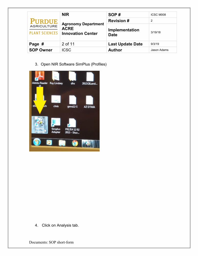
NIR Agronomy Department ACRE Innovation Center
SOP # ICSC M008
Revision # 2
Implementation Date 3/19/18
Page # 2 of 11 Last Update Date 9/3/19
SOP Owner ICSC Author Jason Adams
Documents: SOP short-form
3. Open NIR Software SimPlus (Profiles)
4. Click on Analysis tab.
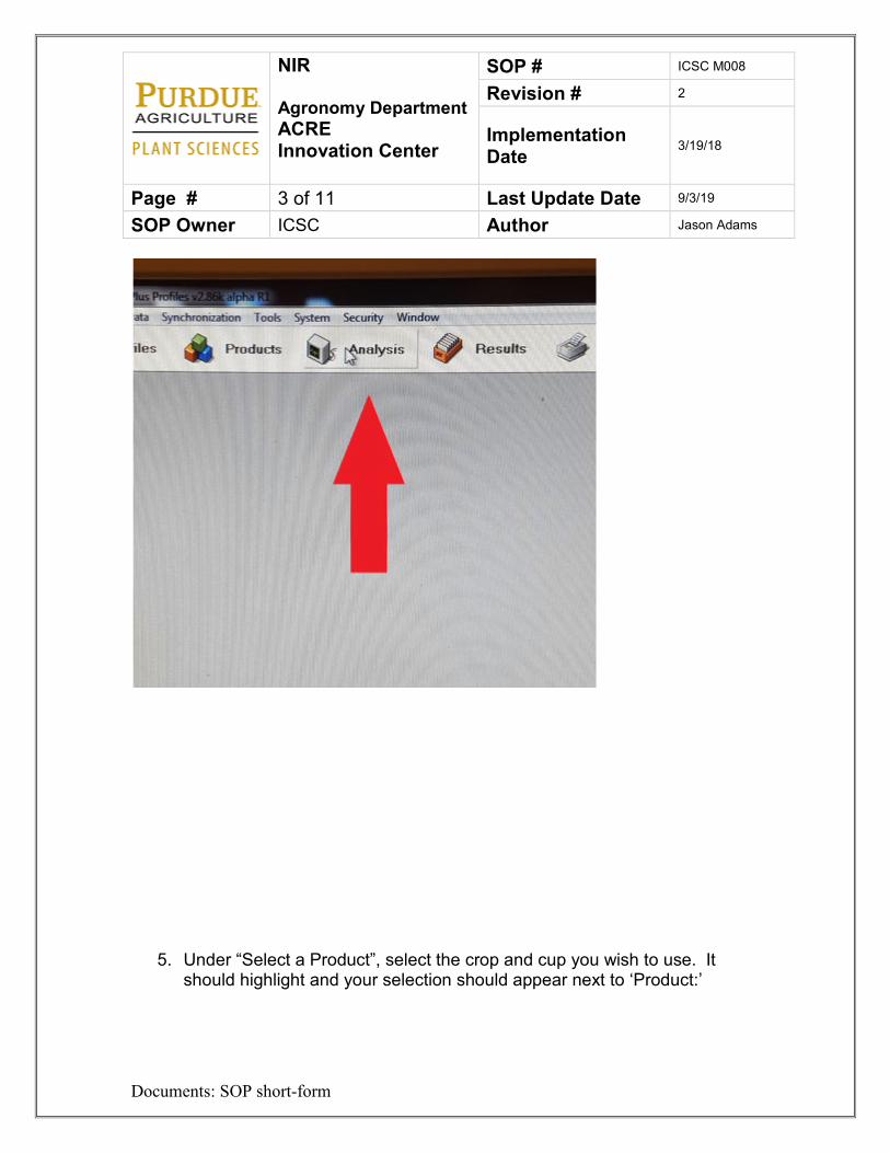
NIR Agronomy Department ACRE Innovation Center
SOP # ICSC M008
Revision # 2
Implementation Date 3/19/18
Page # 3 of 11 Last Update Date 9/3/19
SOP Owner ICSC Author Jason Adams
Documents: SOP short-form
5. Under “Select a Product”, select the crop and cup you wish to use. It should highlight and your selection should appear next to ‘Product:’
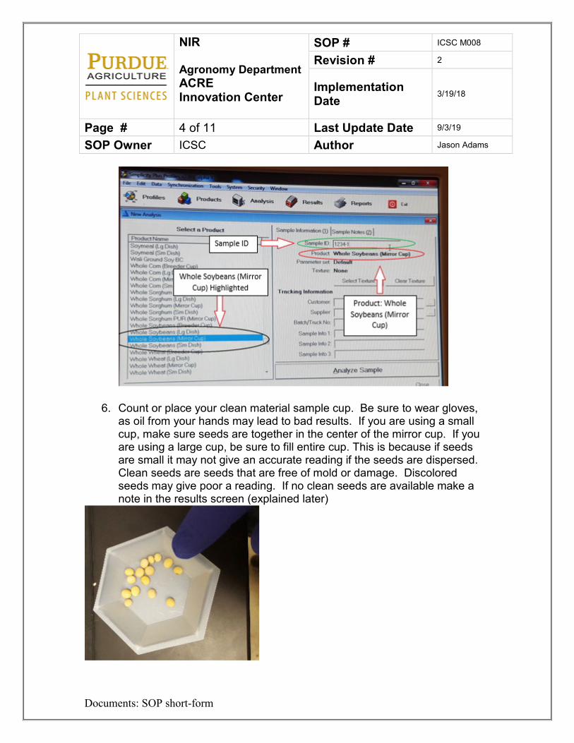
NIR Agronomy Department ACRE Innovation Center
SOP # ICSC M008
Revision # 2
Implementation Date 3/19/18
Page # 4 of 11 Last Update Date 9/3/19
SOP Owner ICSC Author Jason Adams
Documents: SOP short-form
6. Count or place your clean material sample cup. Be sure to wear gloves, as oil from your hands may lead to bad results. If you are using a small cup, make sure seeds are together in the center of the mirror cup. If you are using a large cup, be sure to fill entire cup. This is because if seeds are small it may not give an accurate reading if the seeds are dispersed. Clean seeds are seeds that are free of mold or damage. Discolored seeds may give poor a reading. If no clean seeds are available make a note in the results screen (explained later)
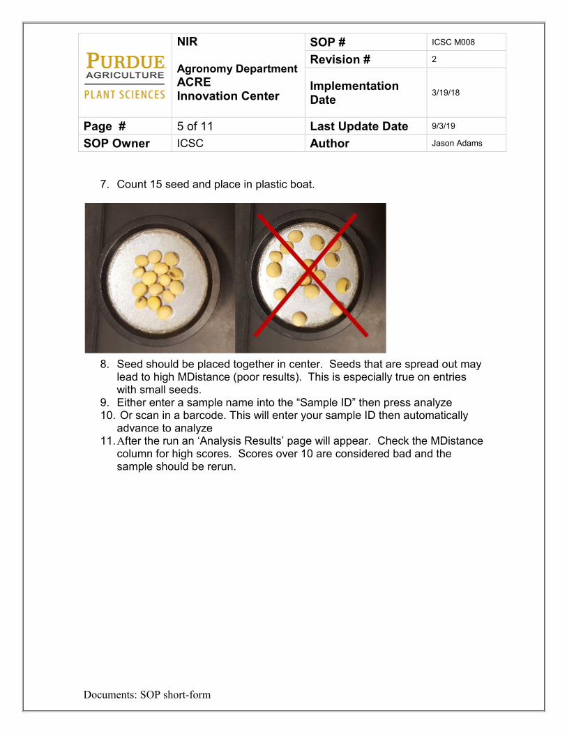
NIR Agronomy Department ACRE Innovation Center
SOP # ICSC M008
Revision # 2
Implementation Date 3/19/18
Page # 5 of 11 Last Update Date 9/3/19
SOP Owner ICSC Author Jason Adams
Documents: SOP short-form
7. Count 15 seed and place in plastic boat.
8. Seed should be placed together in center. Seeds that are spread out may
lead to high MDistance (poor results). This is especially true on entries with small seeds.
9. Either enter a sample name into the “Sample ID” then press analyze 10. Or scan in a barcode. This will enter your sample ID then automatically
advance to analyze 11. After the run an ‘Analysis Results’ page will appear. Check the MDistance
column for high scores. Scores over 10 are considered bad and the sample should be rerun.
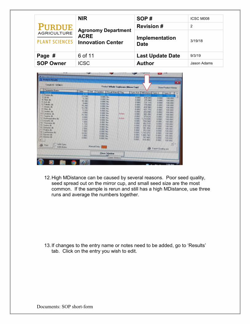
NIR Agronomy Department ACRE Innovation Center
SOP # ICSC M008
Revision # 2
Implementation Date 3/19/18
Page # 6 of 11 Last Update Date 9/3/19
SOP Owner ICSC Author Jason Adams
Documents: SOP short-form
12. High MDistance can be caused by several reasons. Poor seed quality, seed spread out on the mirror cup, and small seed size are the most common. If the sample is rerun and still has a high MDistance, use three runs and average the numbers together.
13. If changes to the entry name or notes need to be added, go to ‘Results’ tab. Click on the entry you wish to edit.
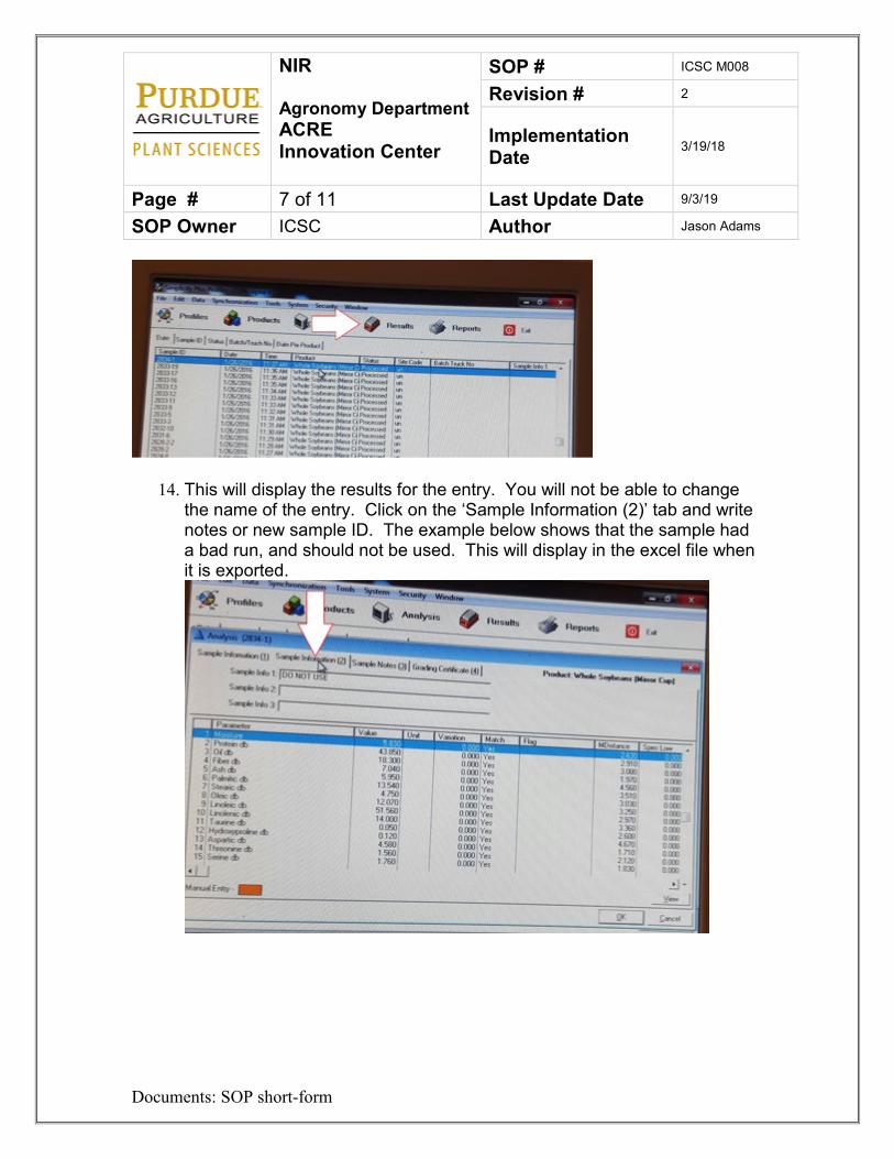
NIR Agronomy Department ACRE Innovation Center
SOP # ICSC M008
Revision # 2
Implementation Date 3/19/18
Page # 7 of 11 Last Update Date 9/3/19
SOP Owner ICSC Author Jason Adams
Documents: SOP short-form
14. This will display the results for the entry. You will not be able to change the name of the entry. Click on the ‘Sample Information (2)’ tab and write notes or new sample ID. The example below shows that the sample had a bad run, and should not be used. This will display in the excel file when it is exported.
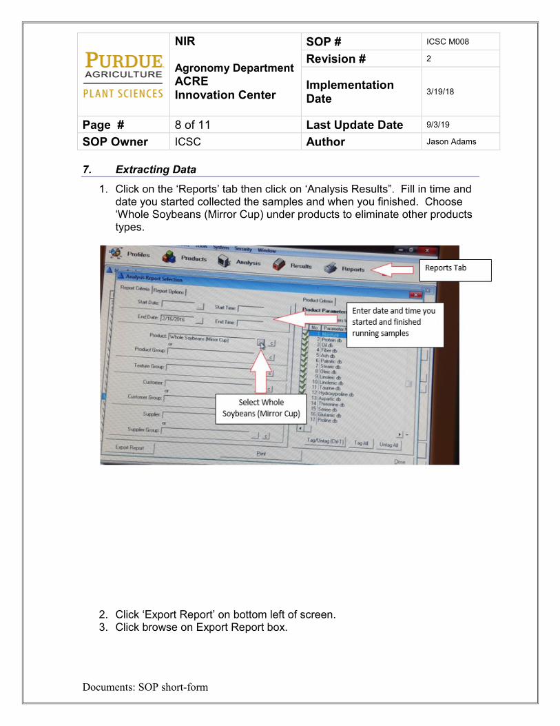
NIR Agronomy Department ACRE Innovation Center
SOP # ICSC M008
Revision # 2
Implementation Date 3/19/18
Page # 8 of 11 Last Update Date 9/3/19
SOP Owner ICSC Author Jason Adams
Documents: SOP short-form
7. Extracting Data
1. Click on the ‘Reports’ tab then click on ‘Analysis Results”. Fill in time and date you started collected the samples and when you finished. Choose ‘Whole Soybeans (Mirror Cup) under products to eliminate other products types.
2. Click ‘Export Report’ on bottom left of screen. 3. Click browse on Export Report box.
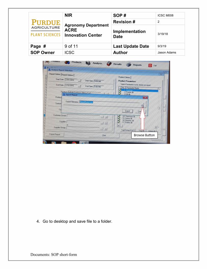
NIR Agronomy Department ACRE Innovation Center
SOP # ICSC M008
Revision # 2
Implementation Date 3/19/18
Page # 9 of 11 Last Update Date 9/3/19
SOP Owner ICSC Author Jason Adams
Documents: SOP short-form
4. Go to desktop and save file to a folder.
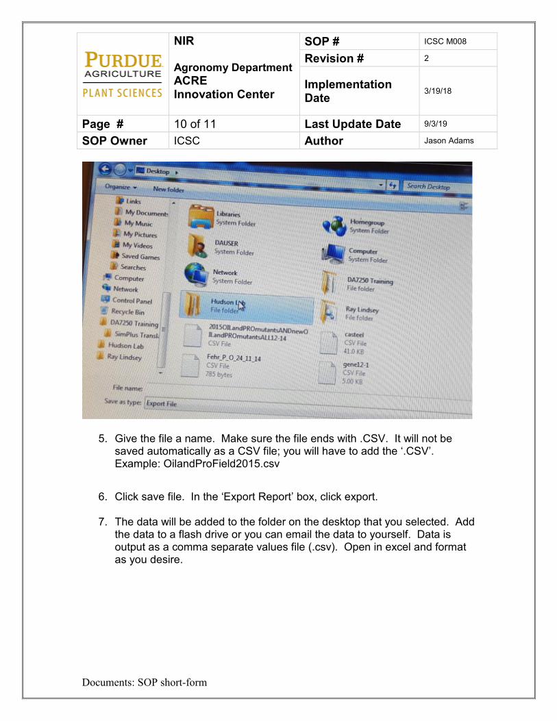
NIR Agronomy Department ACRE Innovation Center
SOP # ICSC M008
Revision # 2
Implementation Date 3/19/18
Page # 10 of 11 Last Update Date 9/3/19
SOP Owner ICSC Author Jason Adams
Documents: SOP short-form
5. Give the file a name. Make sure the file ends with .CSV. It will not be saved automatically as a CSV file; you will have to add the ‘.CSV’. Example: OilandProField2015.csv
6. Click save file. In the ‘Export Report’ box, click export.
7. The data will be added to the folder on the desktop that you selected. Add the data to a flash drive or you can email the data to yourself. Data is output as a comma separate values file (.csv). Open in excel and format as you desire.
NIR Agronomy Department ACRE Innovation Center
SOP # ICSC M008
Revision # 2
Implementation Date 3/19/18
Page # 11 of 11 Last Update Date 9/3/19
SOP Owner ICSC Author Jason Adams
Documents: SOP short-form
8. Lock out Tag out Procedures
1. Remove the plug from the outlet. 2. Place plug cover over the plug. 3. Place the proper lock and tag over the cover. 4. Try to start the NIR. 5. When work is complete remove the tag and lock. 6. Remove the plug cover. 7. Plug the NIR back into the outlet.
9. References
Please see the Innovation Center manager for instructions or owner’s manual.
10. Definitions
ACRE – Agronomy Center for Research and Education NIR – Near infrared PI – Principal Investigator SOP – Standard Operating Procedure
3D Scanner Agronomy Department ACRE Innovation Center
SOP # ICSC M009
Revision # 1
Implementation Date
Page # 1 of 2 Last Reviewed/Update Date
SOP Owner ICSC Author Jason Adams
Documents: SOP short-form
Standard Operating Procedure – 3D Scanner 1. Purpose
Coming Soon. 2. Scope
Coming Soon 3. Prerequisites
Coming Soon 4. Responsibilities
PIs, Technicians, grad students, faculty, farm staff. 5. Safety Concerns
• Coming Soon
6. Procedure
1. Coming Soon
7. References
Please see Phonemics Facility manger or ACRE staff with any questions. 8. Definitions
Trimble RTK Base Station Agronomy Department ACRE Innovation Center
SOP # ICSC M010
Revision # 1
Implementation Date 4/8/19
Page # 1 of 4 Last Reviewed/Update Date
4/8/19
SOP Owner ICSC Author Jason Adams
Documents: SOP short-form
Standard Operating Procedure – Trimble RTK Base Station 1. Purpose
The purpose of this SOP is to give instruction on how to set up and operate the Trimble base station. 2. Scope
Anyone who has a need to use the RTK GPS as a base station or recording GPS locations. 3. Prerequisites
Must go through Innovation Center guidelines and watch facility safety and procedural videos online. You must also be set up in iLabs to reserve the instrument. 4. Responsibilities
PIs, Technicians, grad students, faculty, farm staff. 5. Safety Concerns
• none
6. Procedure
Set up
1. Reserve the Trimble unit in iLabs.
Trimble RTK Base Station Agronomy Department ACRE Innovation Center
SOP # ICSC M010
Revision # 1
Implementation Date 4/8/19
Page # 2 of 4 Last Reviewed/Update Date
4/8/19
SOP Owner ICSC Author Jason Adams
Documents: SOP short-form
2. If you will be using the Trimble as a base station then set the tri-pod in an open area away from buildings or other obstructions.
3. Place black metal antenna bracket to the bottom side of the globe. It will stay in place with magnets. Make sure the silver probe is facing up toward the sky.
4. If you are using the small yellow extension rod then screw it to the tri-pod now.
5. Screw the white Trimble GPS globe to the tri-pod. 6. Assemble the top of the antenna to the base. 7. Screw the antenna to the antenna mounting bracket 8. If you are using the Trimble as a base station then leave the yellow
receiving box in the case. If you will be using the receiver in Rover mode then remove the yellow receiver from the case.
9. Hook up the black antenna cable to the antenna then to the receiver. If this is being used as a base station then run the cable through the access at the bottom of the case.
10. Hook up the yellow satellite cable to the white globe. Then hook the cable to the yellow receiver. If you are using this as a base station then run the cable through the access at the bottom of the case. Note: the yellow cable is fiber optic and very susceptible to breaks and kinks.
11. If you will be using an external power supply (not provided) then you will now hook up the battery cable. Be very careful when hooking up the positive and negative to the battery.
Using the Trimble
1. Turn on the base station and let it find the satellites. a. SV is the number of satellites it sees. b. It will either be in “Base or Rover” mode. c. Net 1 is the radio frequency that is used at ACRE. d. Battery symbol shows the battery life of the internal battery.
Rover Mode
2. If the home screen does not display Rover then press enter. 3. Press enter at Mode Settings.
Trimble RTK Base Station Agronomy Department ACRE Innovation Center
SOP # ICSC M010
Revision # 1
Implementation Date 4/8/19
Page # 3 of 4 Last Reviewed/Update Date
4/8/19
SOP Owner ICSC Author Jason Adams
Documents: SOP short-form
4. Press down until Rover flashes. 5. Press enter until back at Main Screen. 6. If you need to adjust the height of the globe and antenna then press down
arrows until the height settings are displayed. Adjust the height settings and press enter until back at the main screen.
7. To read GPS location press down four times until the GPS coordinates are shown.
Running as base Station – you may also refer to quick reference guide in case.
1. If not is base station mode then press enter at the home screen. 2. Press enter at Mode Setting. 3. Press down until Base flashes. 4. Press enter until you get to the home screen. 5. Then create new base location. 6. Press enter until Edit Current is displayed. 7. Press down arrow and New Base here is displayed. 8. You can rename the location of the base station if you desire. 9. Press enter until you are back at the home screen.
Completion of Project When you are done, press power for 3 seconds then pack everything back into the suitcase. 7. References
Please see Phonemics Facility manger or ACRE staff with any questions. 8. Definitions
ACRE – Agronomy Center for Research and Education GPS – Global Position System ICSC – Indiana Corn and Soybean Innovation Center PI – Principal Investigator
Trimble RTK Base Station Agronomy Department ACRE Innovation Center
SOP # ICSC M010
Revision # 1
Implementation Date 4/8/19
Page # 4 of 4 Last Reviewed/Update Date
4/8/19
SOP Owner ICSC Author Jason Adams
Documents: SOP short-form
RTK – Real Time Kinematic SOP – Standard Operating Procedure
Packet Printer Agronomy Department ACRE Innovation Center
SOP # ICSC P001
Revision # 1
Implementation Date 7/21/17
Page # 1 of 14 Last Update Date 8/6/18
SOP Owner ICSC Author Jason Adams
Documents: SOP short-form
Standard Operating Procedure – Packet Printer 1. Purpose
The purpose of this SOP is to give instruction on how to operate the Packet Printer at the Innovation Center. 2. Scope
Anyone who may need to print seed packets in the Innovation Center. 3. Prerequisites Must go through Innovation Center guidelines and watch facility safety and procedural videos online. You will also need to get set up in iLabs to reserve and turn on the printer. 4. Responsibilities
PIs, Technicians, grad students, undergrads, University employees, faculty, farm staff. 5. Safety Concerns
• Pinch points • Entanglement
6. Printer Procedure
1.) Reserve the printer and turn it on in iLabs. 2.) If packet feeder is not attached, attach them before starting. 3.) Use Very Black ink ONLY. Put 4 cartridges in the imager. 4.) Keep the cartridges in an upright position once the protective caps are removed. You
want to prevent air from entering into the jets on the bottom of the cartridge!!!
Packet Printer Agronomy Department ACRE Innovation Center
SOP # ICSC P001
Revision # 1
Implementation Date 7/21/17
Page # 2 of 14 Last Update Date 8/6/18
SOP Owner ICSC Author Jason Adams
Documents: SOP short-form
5.) Align imagers so the packet will pass directly under the imager. 6.) Adjust knobs on top of imagers so there is enough clearance for packets to travel
through. Test this by manually sliding a packet under the imager with the machine off. 7.) Load packets into the feeder. 8.) Turn printer on with power switch on back of machine. This should light up the orange
Printer Ready light on top of the printer. Press the red button to turn on the printer feeder, it will light up and belts will begin to move. The packet feeder has its own set of controls.
9.) Before you begin to print test feed some packets to ensure that they feed through consistently without catching on anything. After testing, you can shut off both feeders until you are ready to print. Consistency is important to ensure a good print job.
10.) Open Launch Jet Engine GUI from the Home Screen by right clicking it. a. Select “Run as Administrator” b. For User name type (see instructions near printer) c. For password type (see instructions near printer)
11.) THIS STEP IS ESSENTIAL! Open the “Pen Status” tab. Hover your mouse over each bar individually. A box should pop up that says “Very Black or Carton Black” if it says anything else, you need to shut the machine off, take the cartridges out, make sure they are right and then put them back. Reopen the software and check it again. It needs to read the proper ink. The two PrimeX and Very Black inks operate at different volts and they will burn up if they machine is not reading it right. Each cartridge is $75. (The number of jets should be close to or 300) If not remove cartridge and wipe on clean “lint free” cloth or “Kem-wipe”.
12.) Open a packet template. If you do not have a packet template, refer to Supplementary Packet Printing Tips section following this set of instructions. This will walk you through how to properly set everything for printing packets. I recommend saving this template and using it each time. When you print next, you can use the same template as long as the data sheet uses exact same heading names.
13.) Open the Form Design Tab. Load your data source, press the Load Data Source button. It is cream colored with a blue arrow pointing to the right. ALL DATA FILES MUST BE IN .CSV FORM.
14.) Open the Data drop down menu. Click on Modify Schema. In that menu, make sure the box with “First Record Contains Field Names” is checked. Click Ok.
15.) Place data on the form design using the Field Block Button ((F)). The parentheses are blue around the F.
Packet Printer Agronomy Department ACRE Innovation Center
SOP # ICSC P001
Revision # 1
Implementation Date 7/21/17
Page # 3 of 14 Last Update Date 8/6/18
SOP Owner ICSC Author Jason Adams
Documents: SOP short-form
16.) Right click the field book and open properties. Add data field desired and rotate the field block how you would like. Resize and position on the form design.
a. If you are using barcodes, do not overlap them over fields. b. If you overlap between ink cartridges, it will not always line up properly and the
barcodes will not read. 17.) Place rest of your Data on the form design. 18.) When ready to print, press the red square button on the printer to turn the feeder on.
DO NOT HAVE THE PACKET FEEDER ON. Open the print manager tab. Select desired fields to print. Right click and click “Add Fields.” I recommend purging 1-2 packets to ensure cartridges are working properly. To do this, set “Initial Pages to Purge” to 1 or 2.
19.) Click the Green Start Print Job button on the Print manager tab. It will turn gray for about 8-10 seconds. Once it turns red, turn on the packet feeder. Packets will feed through machine and be printed on.
a. The packet feeder will not stop once the data source is done printing so you will need to shut off by pressing the red button. It will keep sending packets through the machine, but it will not print on them.
20.) Once you are done printing you can save your Job. Remove the Ink and place the covers back on them so they do not dry out. Shut the machine off and fill out the form with you information.
21.) It is very important when you remove the ink cartridges. Please keep them upright until the protective caps are replaced. This prevents air from entering into the jets!
Supplementary Printing Tips
P4 Packet Printing basic setup. 1. Setup Screen for Packet Printing
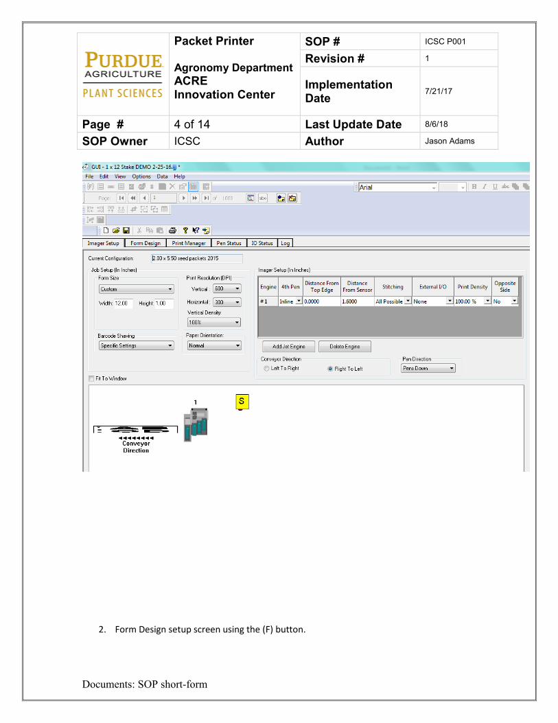
Packet Printer Agronomy Department ACRE Innovation Center
SOP # ICSC P001
Revision # 1
Implementation Date 7/21/17
Page # 4 of 14 Last Update Date 8/6/18
SOP Owner ICSC Author Jason Adams
Documents: SOP short-form
2. Form Design setup screen using the (F) button.
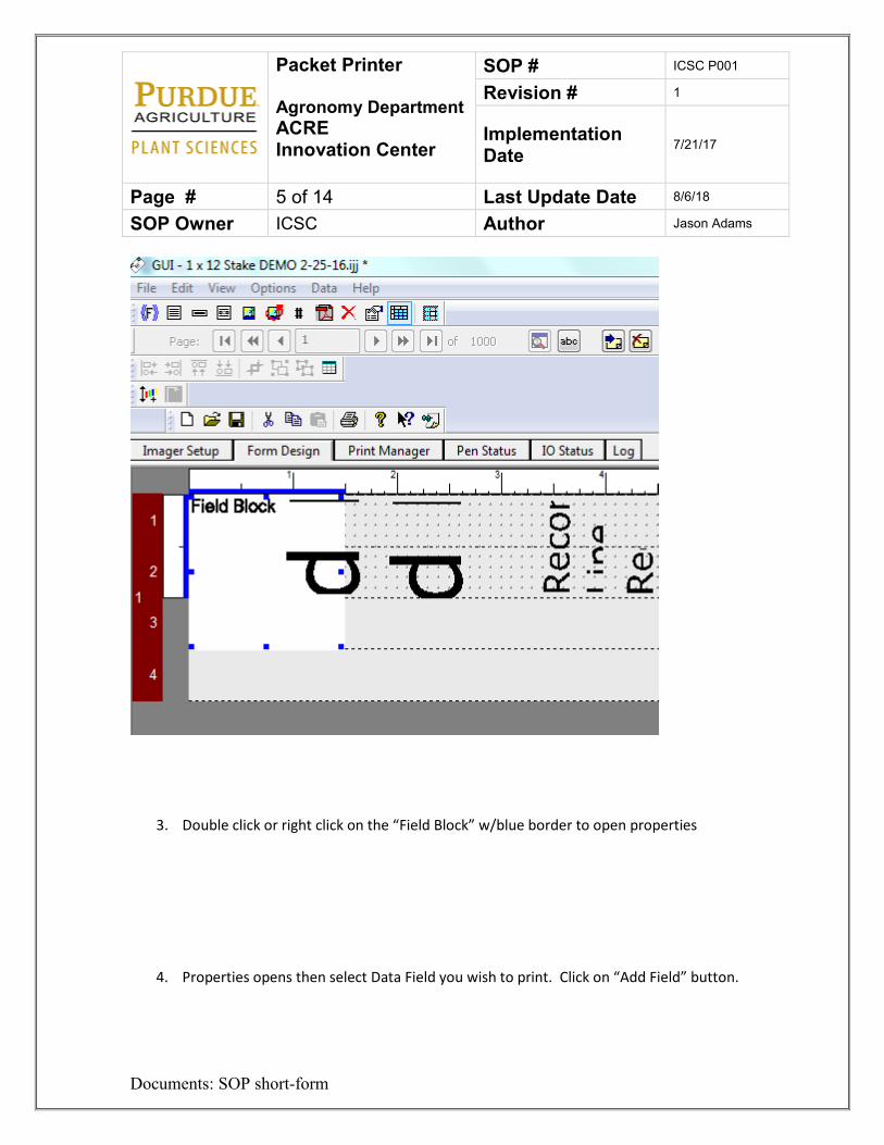
Packet Printer Agronomy Department ACRE Innovation Center
SOP # ICSC P001
Revision # 1
Implementation Date 7/21/17
Page # 5 of 14 Last Update Date 8/6/18
SOP Owner ICSC Author Jason Adams
Documents: SOP short-form
3. Double click or right click on the “Field Block” w/blue border to open properties
4. Properties opens then select Data Field you wish to print. Click on “Add Field” button.

Packet Printer Agronomy Department ACRE Innovation Center
SOP # ICSC P001
Revision # 1
Implementation Date 7/21/17
Page # 6 of 14 Last Update Date 8/6/18
SOP Owner ICSC Author Jason Adams
Documents: SOP short-form
5. Once selected it is highlighted, click on the “Add Field” button and the dialogue box
displays the Field Name inside <<…>>. You can then add a label by typing in front of the << characters.

Packet Printer Agronomy Department ACRE Innovation Center
SOP # ICSC P001
Revision # 1
Implementation Date 7/21/17
Page # 7 of 14 Last Update Date 8/6/18
SOP Owner ICSC Author Jason Adams
Documents: SOP short-form
6. View of Data after print job is created.
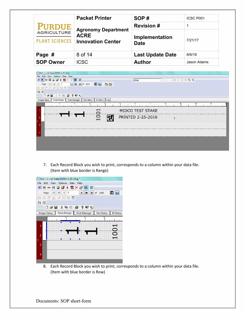
Packet Printer Agronomy Department ACRE Innovation Center
SOP # ICSC P001
Revision # 1
Implementation Date 7/21/17
Page # 8 of 14 Last Update Date 8/6/18
SOP Owner ICSC Author Jason Adams
Documents: SOP short-form
7. Each Record Block you wish to print, corresponds to a column within your data file. (Item with blue border is Range)
8. Each Record Block you wish to print, corresponds to a column within your data file.
(Item with blue border is Row)
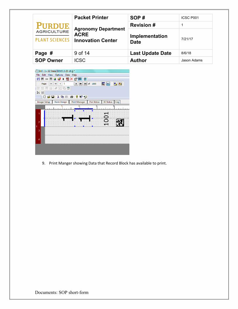
Packet Printer Agronomy Department ACRE Innovation Center
SOP # ICSC P001
Revision # 1
Implementation Date 7/21/17
Page # 9 of 14 Last Update Date 8/6/18
SOP Owner ICSC Author Jason Adams
Documents: SOP short-form
9. Print Manger showing Data that Record Block has available to print.
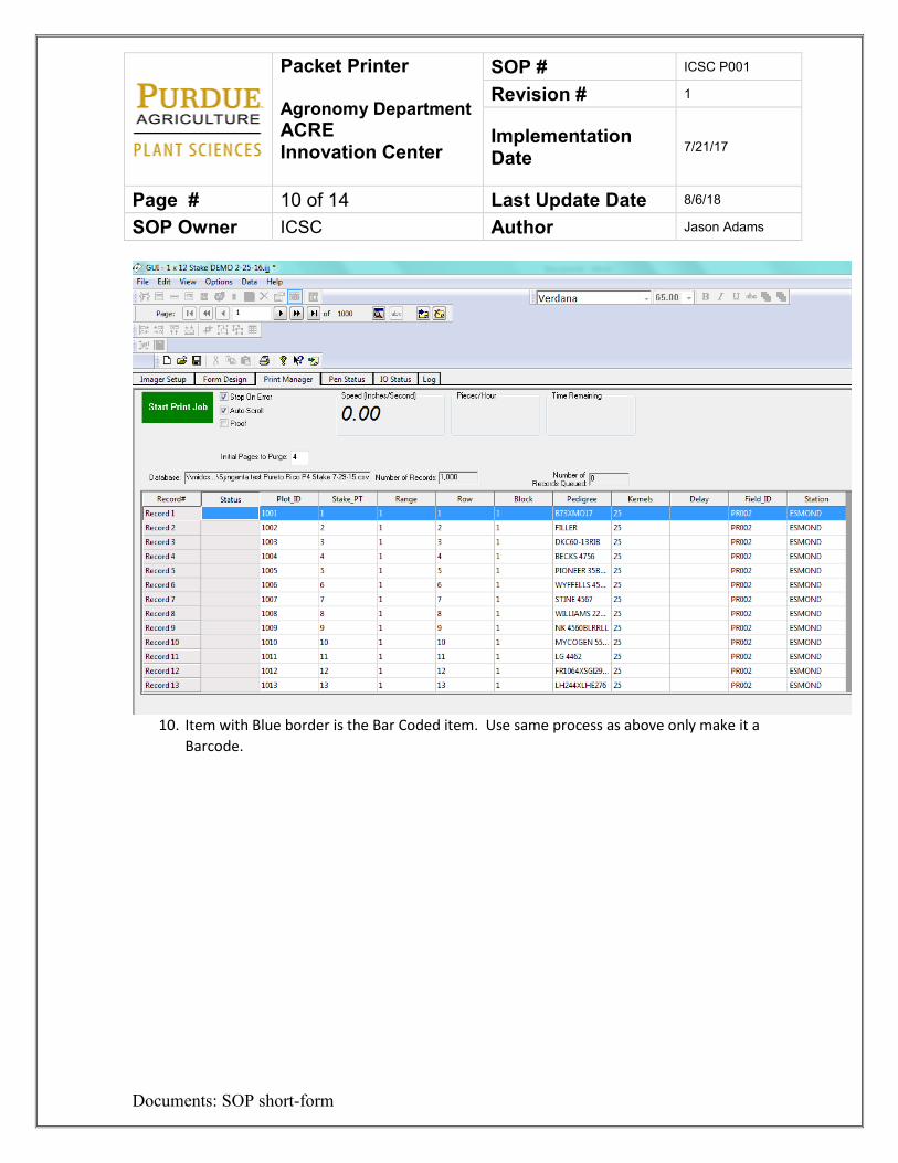
Packet Printer Agronomy Department ACRE Innovation Center
SOP # ICSC P001
Revision # 1
Implementation Date 7/21/17
Page # 10 of 14 Last Update Date 8/6/18
SOP Owner ICSC Author Jason Adams
Documents: SOP short-form
10. Item with Blue border is the Bar Coded item. Use same process as above only make it a
Barcode.
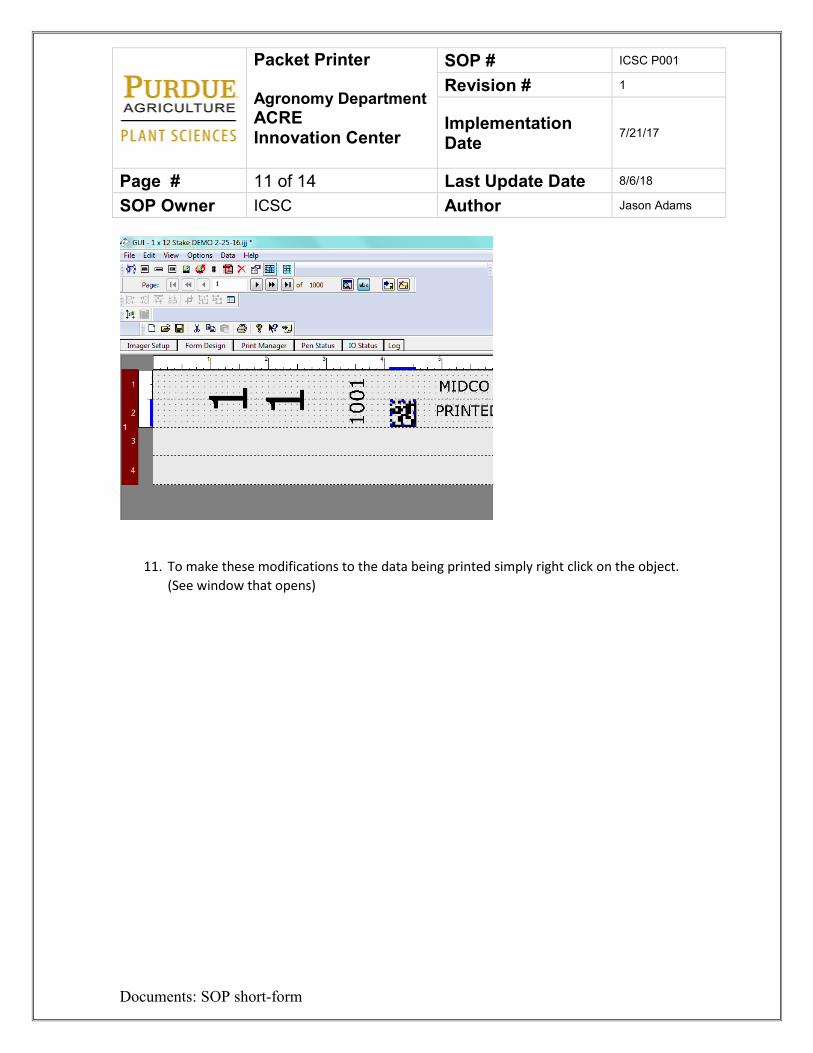
Packet Printer Agronomy Department ACRE Innovation Center
SOP # ICSC P001
Revision # 1
Implementation Date 7/21/17
Page # 11 of 14 Last Update Date 8/6/18
SOP Owner ICSC Author Jason Adams
Documents: SOP short-form
11. To make these modifications to the data being printed simply right click on the object. (See window that opens)
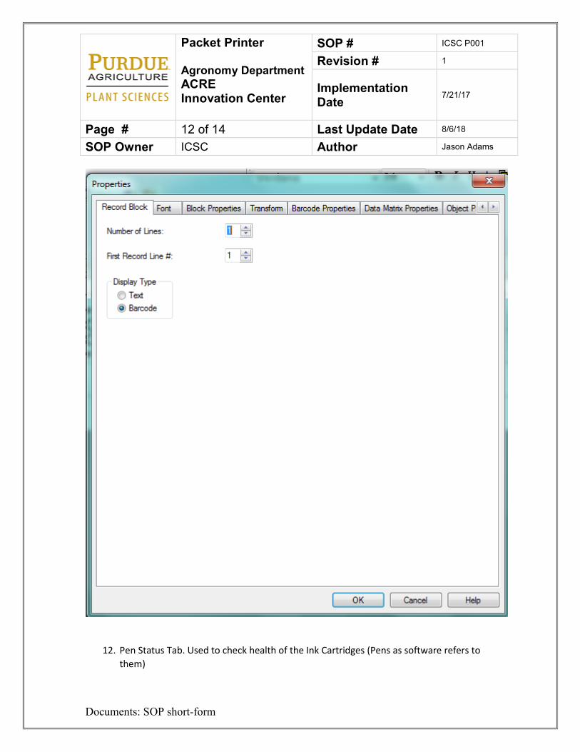
Packet Printer Agronomy Department ACRE Innovation Center
SOP # ICSC P001
Revision # 1
Implementation Date 7/21/17
Page # 12 of 14 Last Update Date 8/6/18
SOP Owner ICSC Author Jason Adams
Documents: SOP short-form
12. Pen Status Tab. Used to check health of the Ink Cartridges (Pens as software refers to them)
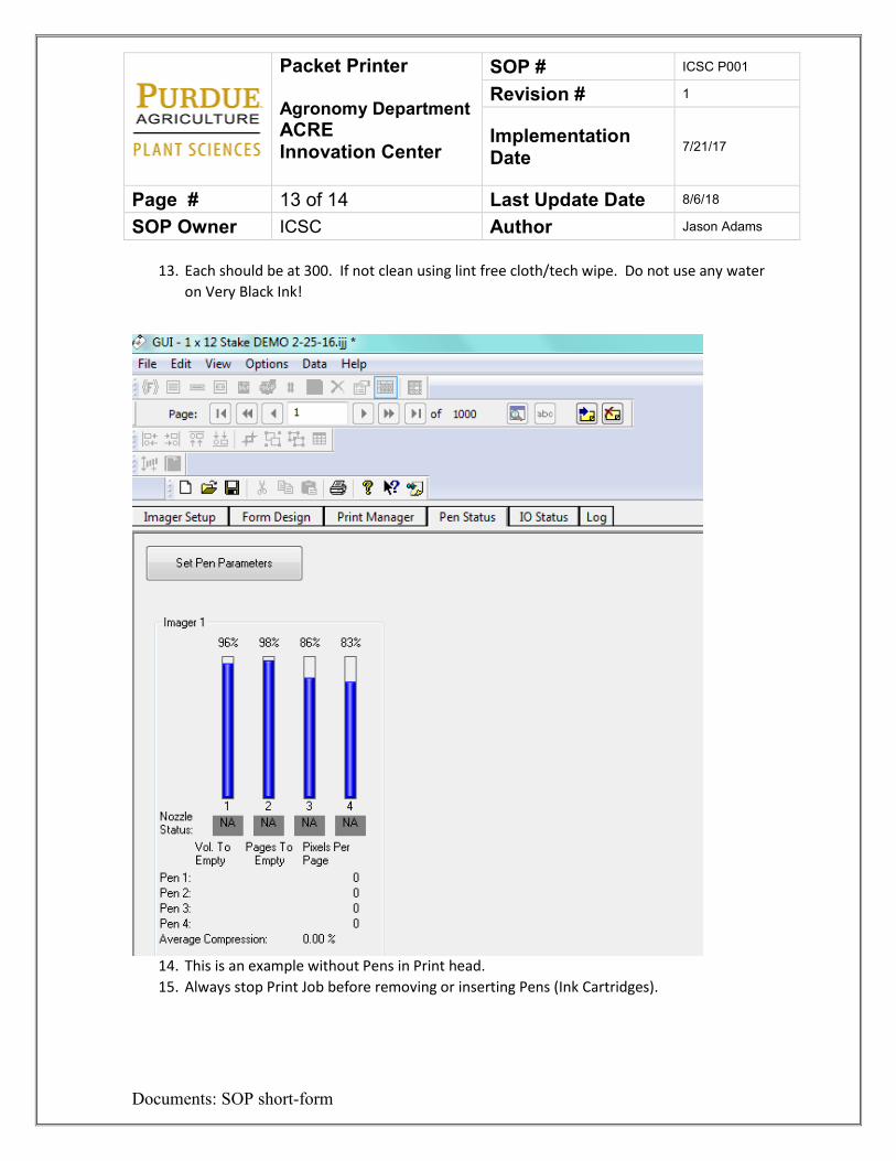
Packet Printer Agronomy Department ACRE Innovation Center
SOP # ICSC P001
Revision # 1
Implementation Date 7/21/17
Page # 13 of 14 Last Update Date 8/6/18
SOP Owner ICSC Author Jason Adams
Documents: SOP short-form
13. Each should be at 300. If not clean using lint free cloth/tech wipe. Do not use any water on Very Black Ink!
14. This is an example without Pens in Print head. 15. Always stop Print Job before removing or inserting Pens (Ink Cartridges).
Packet Printer Agronomy Department ACRE Innovation Center
SOP # ICSC P001
Revision # 1
Implementation Date 7/21/17
Page # 14 of 14 Last Update Date 8/6/18
SOP Owner ICSC Author Jason Adams
Documents: SOP short-form
7. Lockout Tagout Procedures
1. Unplug the printer 2. Place a plug cover, lock and a tag on the plug. 3. Try to re-energize the printer 4. Perform maintenance 5. Remove tag and lock. 6. Plug in the printer.
8. References
Supplemental manuals found in drawers near the printer 9. Definitions
ACRE – Agronomy Center for Research and Education LOTO – Lockout Tag out. The act of locking a machine or device so it may not be
energized during maintenance PI – Principal Investigator Stake Printer- Used to print information on to field packets SOP – Standard Operating Procedure
Stake Printer Agronomy Department ACRE Innovation Center
SOP # ICSC P002
Revision # 2
Implementation Date 7/21/17
Page # 1 of 14 Last Update Date 9/3/19
SOP Owner ICSC Author Jason Adams
Documents: SOP short-form
Standard Operating Procedure – Stake Printer 1. Purpose
The purpose of this SOP is to give instruction on how to operate the Stake Printers at the Innovation Center. 2. Scope
Anyone who may need to print field stakes in the Innovation Center. 3. Prerequisites Must go through Innovation Center guidelines and watch facility safety and procedural videos online. Must Use specific MIDCO stakes. Also must be set up in iLabs to reserve and turn on the printer. 4. Responsibilities
PIs, Technicians, grad students, undergrads, University employees, faculty, farm staff. 5. Safety Concerns
• Pinch points • Entanglement
6. Printer Procedure
1.) Reserve and turn on the printer in ilabs. 2.) Attach stake feeder and tray before starting. If not already done.
a. The Stake feeder has two cords that need to be plugged in. The gray cord goes into the Control Cable port and the side of the machine. The black cord goes in to the Accessory Power port on the back of the machine.
Stake Printer Agronomy Department ACRE Innovation Center
SOP # ICSC P002
Revision # 2
Implementation Date 7/21/17
Page # 2 of 14 Last Update Date 9/3/19
SOP Owner ICSC Author Jason Adams
Documents: SOP short-form
b. Check adjustment of pressure roller to assure proper feeding of the stakes from the feeder to the transport belts. (Too tight stakes will not feed; too loose will not make good contact with the belt and stakes will not “get-up-to-speed”. This can cause miss aligned printing.)
3.) Use PrimeX Black ink ONLY. Put both cartridges in the imager closest to the feeder. 4.) Keep the cartridges in an upright position once the protective caps are removed. You
want to prevent air from entering into the jets on the bottom of the cartridge!!! 5.) Set feeder speed (knob on top of Printer) to a slower speed than packets. You will need
to adjust this to a faster speed as you begin testing. 6.) Align imager so the Stake will pass directly under the imager. (This is the top imager
closest to the feeder. Move the lower imager off to the side next to the control panel). 7.) Adjust knobs on top of imagers so there is enough clearance for stakes to travel
through. Test this by manually sliding a take under the imager with the machine off. 8.) Load stakes into the feeder with the top of the stake towards the printer. You must use
MIDCO approved stakes. 9.) Turn printer on with power switch on back of machine. This should light up the orange
Printer Ready light on top of the machine. Press the red button to turn on the printer feeder, it will light up and belts will begin to move. The stake feeder has its own set of controls. The red square button will need to be lit up. If it is not, press it. To start the feeder, press the round green button, to stop it press the round red button.
10.) Before you begin to print test feed some stake to ensure that they feed through consistently without catching on anything. After testing, you can shut off both feeders until you are ready to print. Consistency is important to ensure a good print job.
11.) Open Launch Jet Engine GUI on your desktop by right clicking a. Select “Run as Administrator” b. For User name type (see instruction at workstation) c. For password type (see instructions by workstation)
12.) THIS STEP IS ESSENTIAL! Open the “Pen Status” tab. Hover your mouse over each bar individually. A box should pop up that says “PrimeX Black” if it says anything else, you need to shut the machine off, take the cartridges out, make sure they are right and then put them back. Reopen the software and check it again. It needs to read the proper ink. The two PrimeX and Very Black inks operate at different volts and they will burn up if they machine is not reading it right. Each cartridge is $75. (The number of jets should be close to or 300) If not remove cartridge and wipe on clean “lint free” cloth or “Kem-wipe”.
Stake Printer Agronomy Department ACRE Innovation Center
SOP # ICSC P002
Revision # 2
Implementation Date 7/21/17
Page # 3 of 14 Last Update Date 9/3/19
SOP Owner ICSC Author Jason Adams
Documents: SOP short-form
13.) Open a stake template. If you do not have a stake template, refer to P4 Stake Printing Basic Setup section following this set of instructions. This will walk you through how to properly set everything for printing stakes. I recommend saving this template and using it each time. When you print next, you can use the same template as long as the data sheet uses exact same heading names.
14.) Open the Form Design Tab. Load you data source, press the Load Data Source button. It is cream colored with a blue arrow pointing to the right. ALL DATA FILES MUST BE IN .CSV FORM.
15.) Open the Data drop down menu. Click on Modify Schema. In that menu, make sure the box with “First Record Contains Field Names” is checked. Click Ok.
16.) Place data on the form design using the Field Block Button ((F)). The parentheses are blue around the F.
17.) Right click the field bock and open properties. Add data field desired and rotate the field block how you would like. Resize and position on the form design. Place in fields 1 and 2 only. Fields 3 and 4 will not work because we are only using #1 and #2 ink cartridges to print on stakes. I recommend not placing any data above the ½-inch mark.
a. If you are using barcodes, do not overlap them over fields. (Keep them on either pen 1 or pen 2 only)
b. If you overlap between pens, it will not always line up properly and the barcodes will not read.
18.) Place rest of your Data on the form design. 19.) When ready to print, press the red square button on the printer to turn the feeder on.
DO NOT HAVE THE STAKE FEEDER ON. Open the print manager tab. Select desired fields to print. Right click and click “Add Fields.” I recommend purging 1 stake to ensure cartridges are working properly. To do this, set “Initial Pages to Purge” to 1.
20.) Click the Green Start Print Job button on the Print manager tab. It will turn gray for about 8-10 seconds. Once it turns red, turn on the stake feeder by pressing the round green button. Stakes will feed through machine and be printed on.
a. The stake feeder will not stop once the data source is done printing so you will need to shut off by pressing the red button. It will keep sending stakes through the machine, but it will not print on them.
21.) Once you are done printing you can save your Job. Remove the Ink and place the covers back on them so they do not dry out. Shut the machine off and fill out the form with you information.
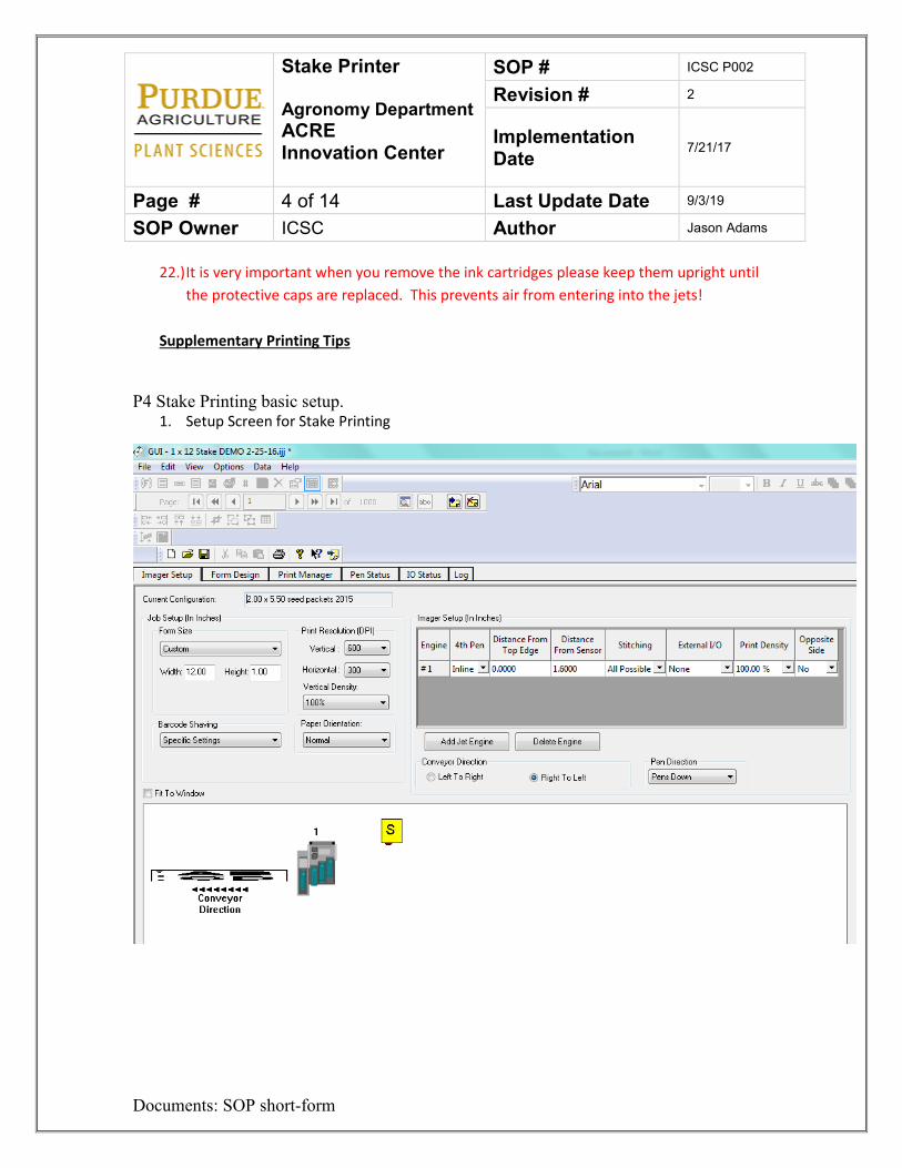
Stake Printer Agronomy Department ACRE Innovation Center
SOP # ICSC P002
Revision # 2
Implementation Date 7/21/17
Page # 4 of 14 Last Update Date 9/3/19
SOP Owner ICSC Author Jason Adams
Documents: SOP short-form
22.) It is very important when you remove the ink cartridges please keep them upright until the protective caps are replaced. This prevents air from entering into the jets!
Supplementary Printing Tips
P4 Stake Printing basic setup. 1. Setup Screen for Stake Printing
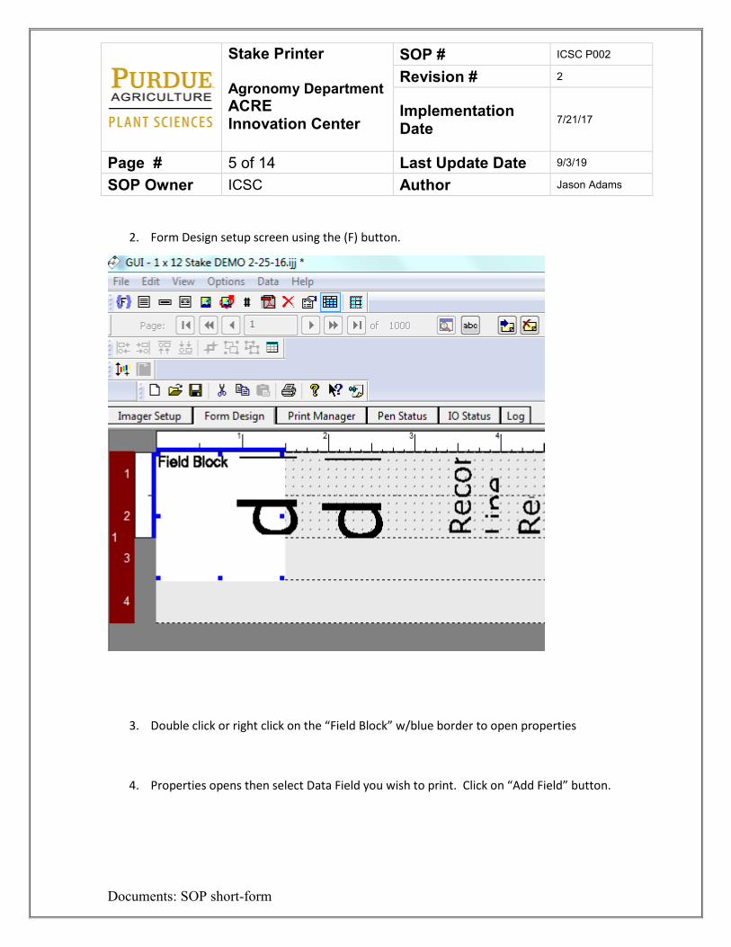
Stake Printer Agronomy Department ACRE Innovation Center
SOP # ICSC P002
Revision # 2
Implementation Date 7/21/17
Page # 5 of 14 Last Update Date 9/3/19
SOP Owner ICSC Author Jason Adams
Documents: SOP short-form
2. Form Design setup screen using the (F) button.
3. Double click or right click on the “Field Block” w/blue border to open properties
4. Properties opens then select Data Field you wish to print. Click on “Add Field” button.
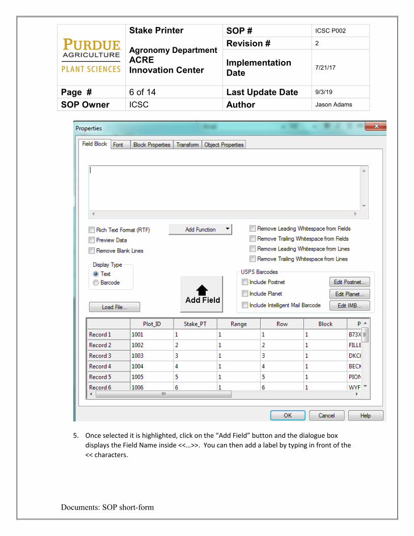
Stake Printer Agronomy Department ACRE Innovation Center
SOP # ICSC P002
Revision # 2
Implementation Date 7/21/17
Page # 6 of 14 Last Update Date 9/3/19
SOP Owner ICSC Author Jason Adams
Documents: SOP short-form
5. Once selected it is highlighted, click on the “Add Field” button and the dialogue box
displays the Field Name inside <<…>>. You can then add a label by typing in front of the << characters.
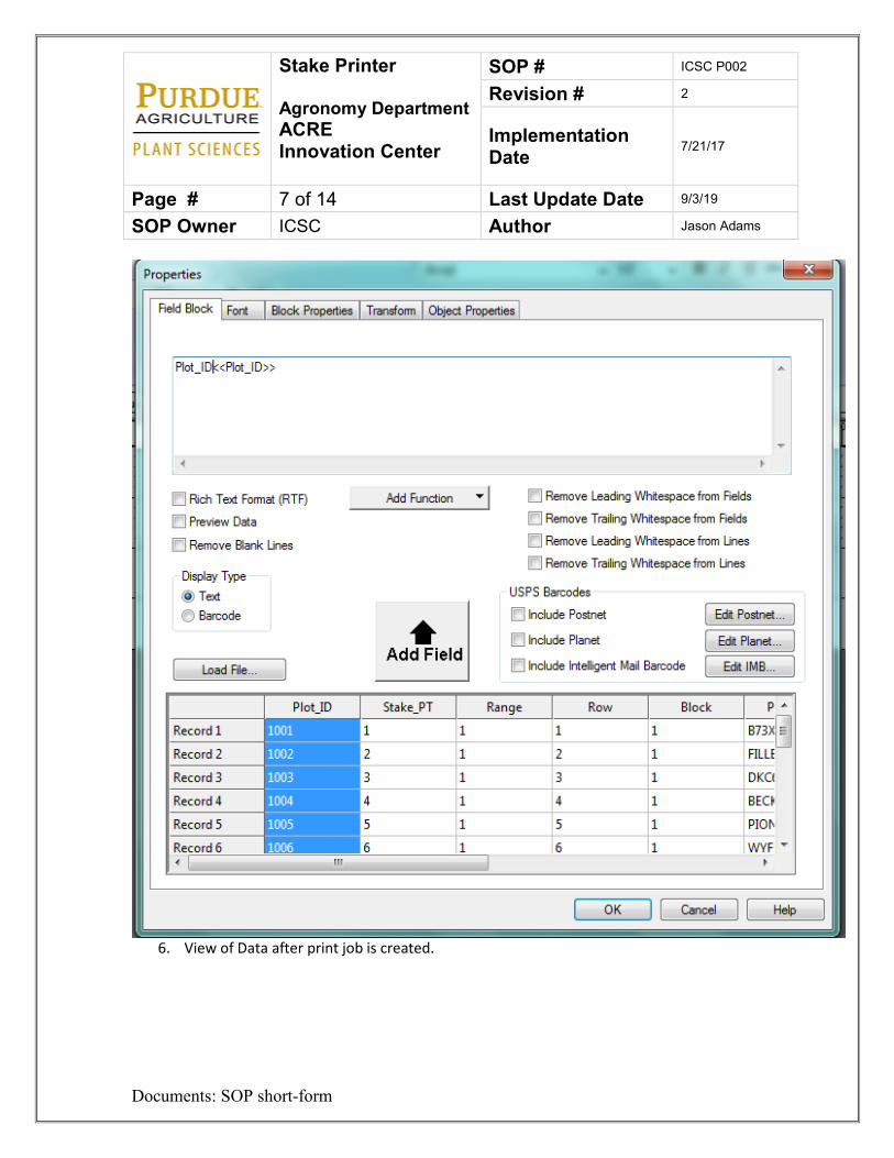
Stake Printer Agronomy Department ACRE Innovation Center
SOP # ICSC P002
Revision # 2
Implementation Date 7/21/17
Page # 7 of 14 Last Update Date 9/3/19
SOP Owner ICSC Author Jason Adams
Documents: SOP short-form
6. View of Data after print job is created.

Stake Printer Agronomy Department ACRE Innovation Center
SOP # ICSC P002
Revision # 2
Implementation Date 7/21/17
Page # 8 of 14 Last Update Date 9/3/19
SOP Owner ICSC Author Jason Adams
Documents: SOP short-form
7. Each Record Block you wish to print, corresponds to a column within your data file. (Item with blue border is Range)
8. Each Record Block you wish to print, corresponds to a column within your data file.
(Item with blue border is Row)

Stake Printer Agronomy Department ACRE Innovation Center
SOP # ICSC P002
Revision # 2
Implementation Date 7/21/17
Page # 9 of 14 Last Update Date 9/3/19
SOP Owner ICSC Author Jason Adams
Documents: SOP short-form
9. Print Manger showing Data that Record Block has available to print.
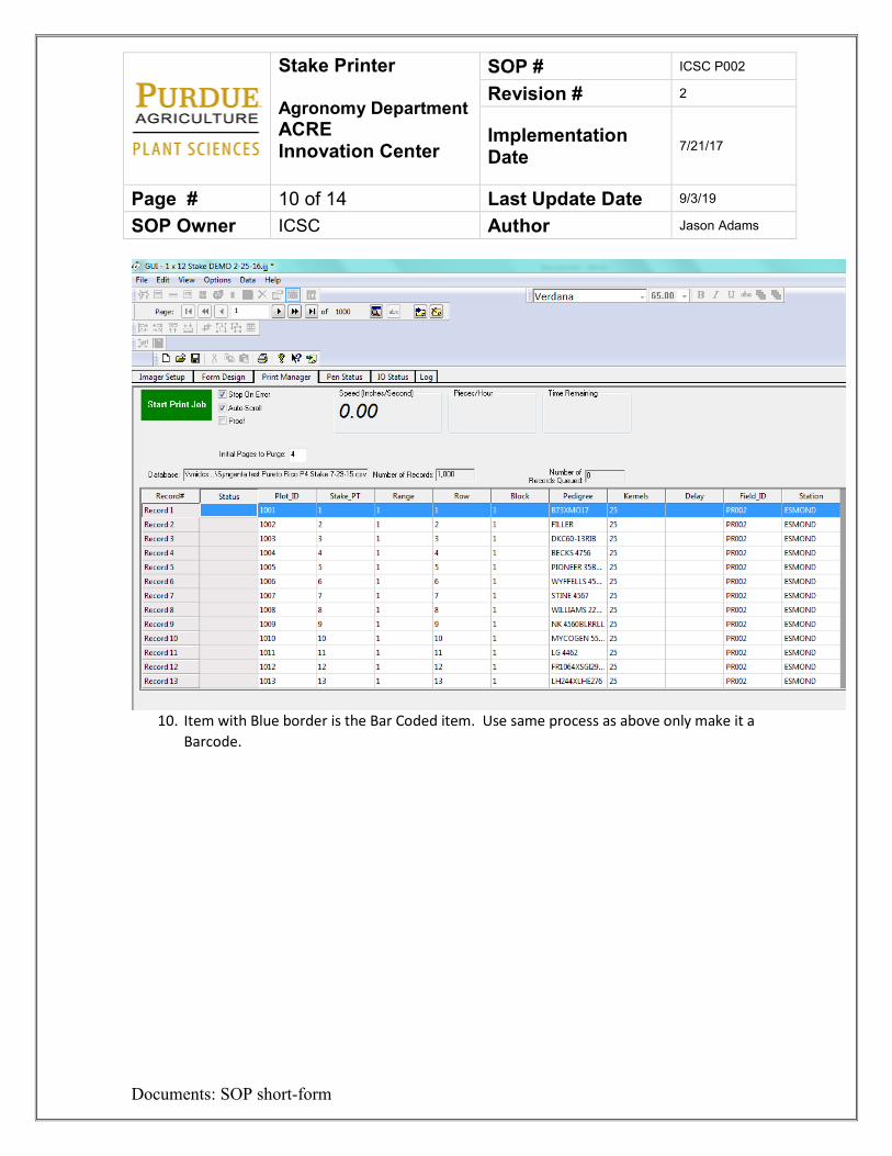
Stake Printer Agronomy Department ACRE Innovation Center
SOP # ICSC P002
Revision # 2
Implementation Date 7/21/17
Page # 10 of 14 Last Update Date 9/3/19
SOP Owner ICSC Author Jason Adams
Documents: SOP short-form
10. Item with Blue border is the Bar Coded item. Use same process as above only make it a
Barcode.
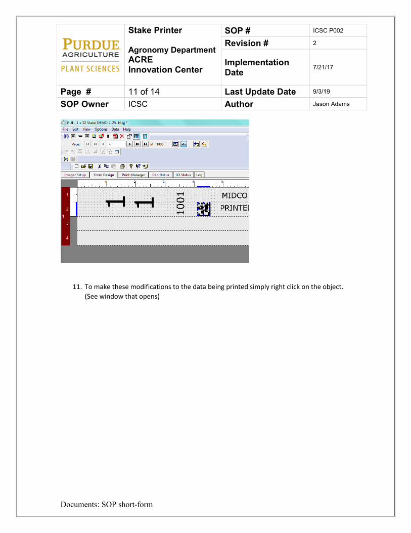
Stake Printer Agronomy Department ACRE Innovation Center
SOP # ICSC P002
Revision # 2
Implementation Date 7/21/17
Page # 11 of 14 Last Update Date 9/3/19
SOP Owner ICSC Author Jason Adams
Documents: SOP short-form
11. To make these modifications to the data being printed simply right click on the object. (See window that opens)
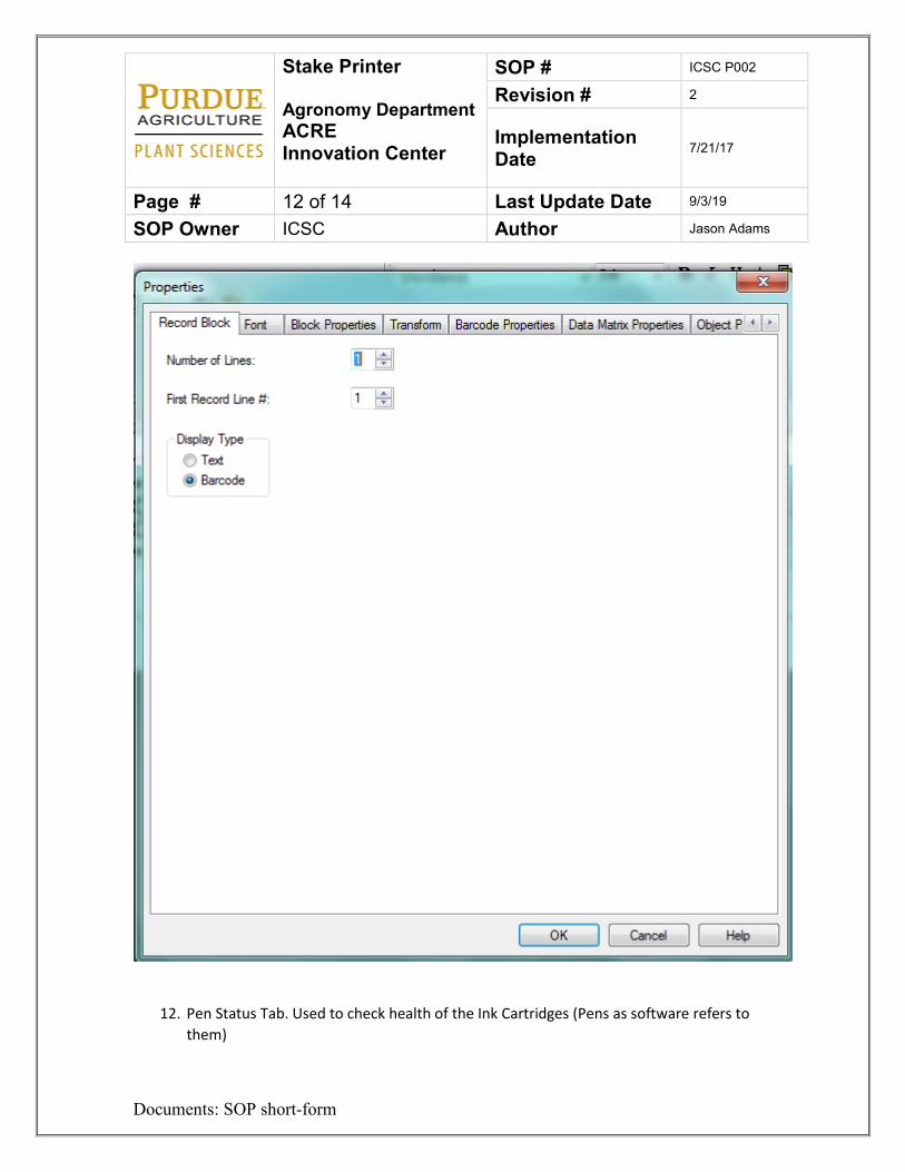
Stake Printer Agronomy Department ACRE Innovation Center
SOP # ICSC P002
Revision # 2
Implementation Date 7/21/17
Page # 12 of 14 Last Update Date 9/3/19
SOP Owner ICSC Author Jason Adams
Documents: SOP short-form
12. Pen Status Tab. Used to check health of the Ink Cartridges (Pens as software refers to them)
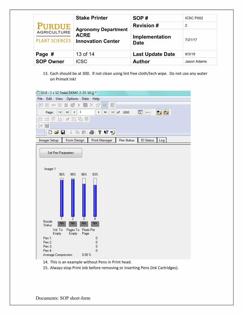
Stake Printer Agronomy Department ACRE Innovation Center
SOP # ICSC P002
Revision # 2
Implementation Date 7/21/17
Page # 13 of 14 Last Update Date 9/3/19
SOP Owner ICSC Author Jason Adams
Documents: SOP short-form
13. Each should be at 300. If not clean using lint free cloth/tech wipe. Do not use any water on PrimeX Ink!
14. This is an example without Pens in Print head. 15. Always stop Print Job before removing or inserting Pens (Ink Cartridges).
Stake Printer Agronomy Department ACRE Innovation Center
SOP # ICSC P002
Revision # 2
Implementation Date 7/21/17
Page # 14 of 14 Last Update Date 9/3/19
SOP Owner ICSC Author Jason Adams
Documents: SOP short-form
For setup of printing on paper, envelopes or any other paper products follow the same basic procedure. Only difference is you will be using the “Very Black” ink, which is water, based, number of Ink Cartridges and the size of your form.
7. Lockout Tagout Procedures
1. Unplug the printer 2. Place a plug cover, lock and a tag on the plug. 3. Try to re-energize the printer 4. Perform maintenance 5. Remove tag and lock. 6. Plug in the printer.
8. References
Please watch the instructional video or see Innovation Center manager for instructions or owner’s manual. 9. Definitions
ACRE – Agronomy Center for Research and Education LOTO – Lockout Tag out. The act of locking a machine or device so it may not be
energized during maintenance PI – Principal Investigator Stake Printer- Used to print information on to field stakes SOP – Standard Operating Procedure
3D Printer Agronomy Department ACRE Innovation Center
SOP # ICSC P003
Revision # 1
Implementation Date 10/31/17
Page # 1 of 6 Last Update Date 8/6/18
SOP Owner ICSC Author Jason Adams
Documents: SOP short-form
Standard Operating Procedure – 3D Printer 1. Purpose
The purpose of this SOP is to give instruction on how to operate the 3D Printer at the Innovation Center. 2. Scope
Anyone who may need to print three-dimensional objects for use in the Innovation Center research building or on their grant project. 3. Prerequisites Must go through Innovation Center guidelines and watch facility safety and procedural videos online. 4. Responsibilities
PIs, Technicians, graduate students, undergrads, University employees, faculty, farm staff. 5. Safety Concerns
• Burns • Pinch Points
6. Procedure
Preparing the model
1. The software that prepares models for 3D printing on the Zortrax printers is called Z-Suite. You may use any 3D modeling software that you are comfortable using to create your file, as long as you are able to output it as a .stl.
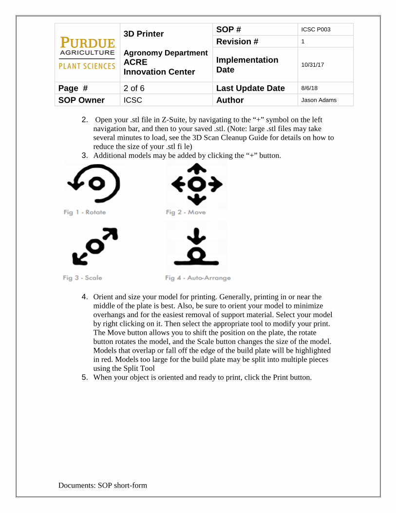
3D Printer Agronomy Department ACRE Innovation Center
SOP # ICSC P003
Revision # 1
Implementation Date 10/31/17
Page # 2 of 6 Last Update Date 8/6/18
SOP Owner ICSC Author Jason Adams
Documents: SOP short-form
2. Open your .stl file in Z-Suite, by navigating to the “+” symbol on the left navigation bar, and then to your saved .stl. (Note: large .stl files may take several minutes to load, see the 3D Scan Cleanup Guide for details on how to reduce the size of your .stl fi le)
3. Additional models may be added by clicking the “+” button.
4. Orient and size your model for printing. Generally, printing in or near the middle of the plate is best. Also, be sure to orient your model to minimize overhangs and for the easiest removal of support material. Select your model by right clicking on it. Then select the appropriate tool to modify your print. The Move button allows you to shift the position on the plate, the rotate button rotates the model, and the Scale button changes the size of the model. Models that overlap or fall off the edge of the build plate will be highlighted in red. Models too large for the build plate may be split into multiple pieces using the Split Tool
5. When your object is oriented and ready to print, click the Print button.
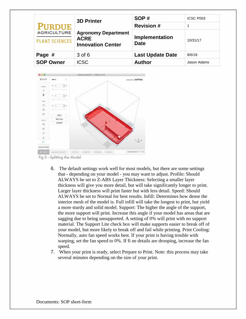
3D Printer Agronomy Department ACRE Innovation Center
SOP # ICSC P003
Revision # 1
Implementation Date 10/31/17
Page # 3 of 6 Last Update Date 8/6/18
SOP Owner ICSC Author Jason Adams
Documents: SOP short-form
6. The default settings work well for most models, but there are some settings that - depending on your model - you may want to adjust. Profile: Should ALWAYS be set to Z-ABS Layer Thickness: Selecting a smaller layer thickness will give you more detail, but will take significantly longer to print. Larger layer thickness will print faster but with less detail. Speed: Should ALWAYS be set to Normal for best results. Infill: Determines how dense the interior mesh of the model is. Full infill will take the longest to print, but yield a more sturdy and solid model. Support: The higher the angle of the support, the more support will print. Increase this angle if your model has areas that are sagging due to being unsupported. A setting of 0% will print with no support material. The Support Lite check box will make supports easier to break off of your model, but more likely to break off and fail while printing. Print Cooling: Normally, auto fan speed works best. If your print is having trouble with warping, set the fan speed to 0%. If fi ne details are drooping, increase the fan speed.
7. When your print is ready, select Prepare to Print. Note: this process may take several minutes depending on the size of your print.
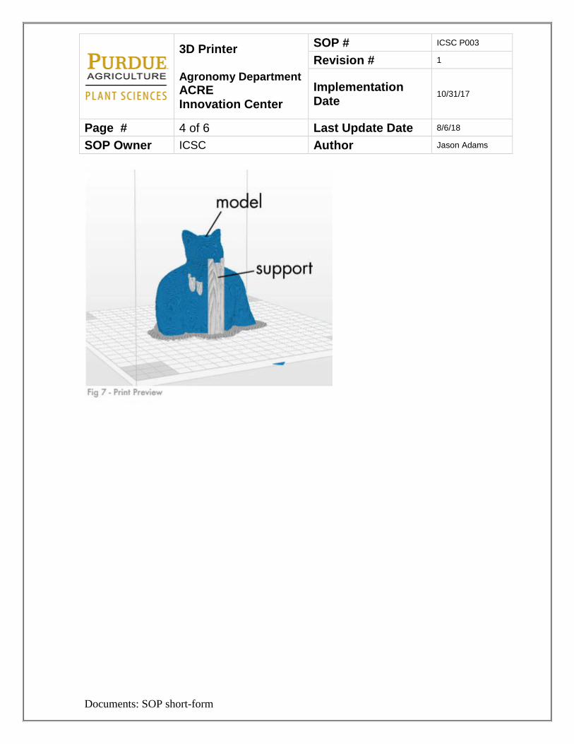
3D Printer Agronomy Department ACRE Innovation Center
SOP # ICSC P003
Revision # 1
Implementation Date 10/31/17
Page # 4 of 6 Last Update Date 8/6/18
SOP Owner ICSC Author Jason Adams
Documents: SOP short-form
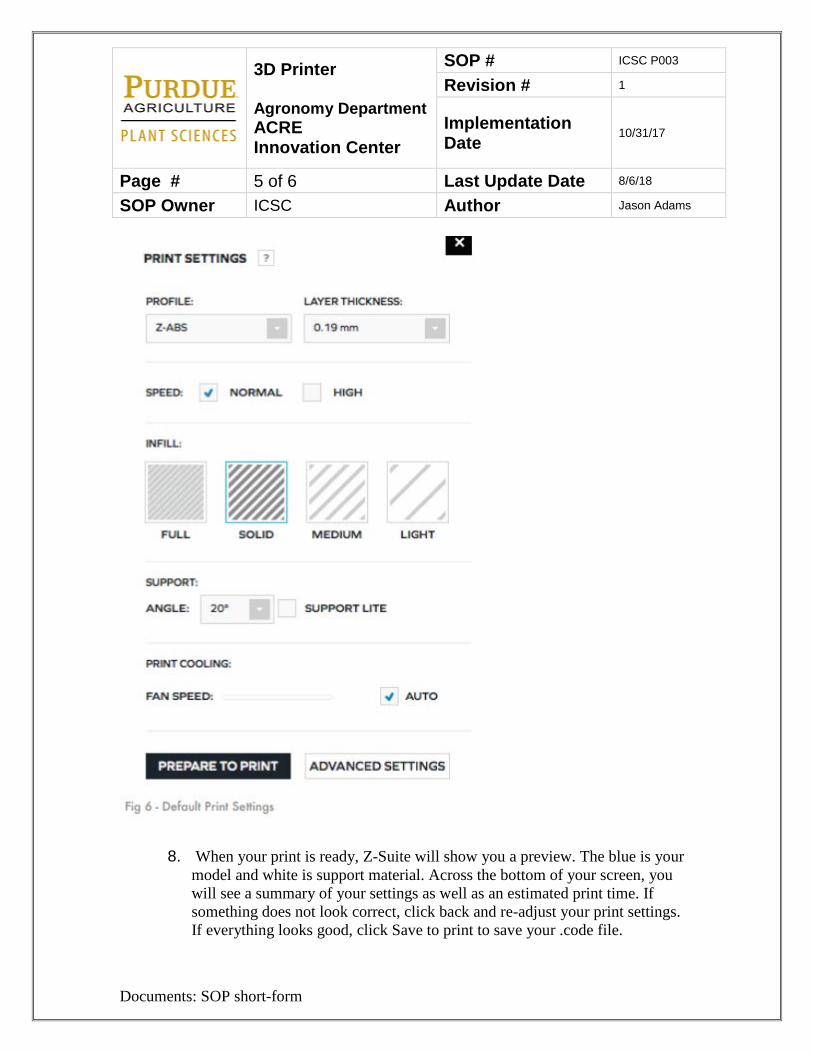
3D Printer Agronomy Department ACRE Innovation Center
SOP # ICSC P003
Revision # 1
Implementation Date 10/31/17
Page # 5 of 6 Last Update Date 8/6/18
SOP Owner ICSC Author Jason Adams
Documents: SOP short-form
8. When your print is ready, Z-Suite will show you a preview. The blue is your model and white is support material. Across the bottom of your screen, you will see a summary of your settings as well as an estimated print time. If something does not look correct, click back and re-adjust your print settings. If everything looks good, click Save to print to save your .code file.
3D Printer Agronomy Department ACRE Innovation Center
SOP # ICSC P003
Revision # 1
Implementation Date 10/31/17
Page # 6 of 6 Last Update Date 8/6/18
SOP Owner ICSC Author Jason Adams
Documents: SOP short-form
9. Copy your .zcode file to a USB stick or memory card and insert it into the printer
10. Insert the SD card into the printer Preparing the printer
1. Turn on the printer 2. Load the spool with the material on the spool holder at the back of the printer. 3. Load the material through the extruder 4. Turn the knob to the model being printed 5. Push knob to begin the process
7. Lockout Tag out
1. Unplug the printer 2. Place a plug cover over the plug 3. Lock and tag the cover 4. Try to re-energize the printer 5. Perform maintenance 6. Remove lock and tag 7. Remover cover 8. Plug back into outlet
8. References
Please watch the instructional video or see Innovation Center manager for instructions or owner’s manual. 9. Definitions
ACRE – Agronomy Center for Research and Education 3D Printer- Used to print three-dimensional objects LOTO – Lockout Tag out. Protocol used for safely disabling equipment to be
able to safely service equipment. PI – Principal Investigator SOP – Standard Operating Procedure