stability analysis and feasibility of pillar … for superficial coal mines. ... the aspects of land...
TRANSCRIPT

Indian Journal of Fundamental and Applied Life Sciences ISSN: 2231– 6345 (Online)
An Open Access, Online International Journal Available at www.cibtech.org/sp.ed/jls/2015/03/jls.htm
2015 Vol. 5 (S3), pp. 823-837/Motevalian and Gholamnejad
Research Article
© Copyright 2014 | Centre for Info Bio Technology (CIBTech) 823
STABILITY ANALYSIS AND FEASIBILITY OF PILLAR RECOVERY
INEXTRACTION WORKPLACE OF SALT ROCKMINING AT
GHAPLOGH REGION AT KHOY
Afshin Motevalian1 and *Javad Gholamnejad
2
1Department of Mining Engineering, Bafgh Branch, Islamic Azad University, Bafgh, Iran
2Department of Mining and Metallurgical Engineering, Yazd University, Yazd, Iran
*Author for Correspondence
ABSTRACT
The article analyzes the stability and feasibility of pillar mining recovery in extraction workplace of salt rock mining at Ghaplogh region at Khoy. The final goal of this paper is to achieve the highest recovery
rate of pillar at salt rock mine in Ghaplogh to the final collapse of the mine roof. Finding the model of
plant behavior during the recovery process, which has both the best results in terms of withdrawal of
pillars and the lowest peripheral cost is one of the mine’s needs. Because of the high cost of maintenance of the mine and due to having salt scoria, the workplace is completely destroyed and changed into the
open pit. Also, because the scoria is salt, the scoria can be sold after the destruction of the workplace. In
the studied mine, withdrawal from the pillars is gradual and returning and is from the end of the workplace toward the entrance and exit doorway. First, the coordinates of the workplace has been drawn
using Auto Cad 2D software and for drawing geometric modeling, FLAC2D software has been used. The
results indicate that up to before the collapse of the roof, the entire large and retaining pillar can be recovered. Also, the points with critical stress where the stresses have risen over the resistance of mineral
material were created only at the pillars and at the junction of the corridor and the created pillars. This
possibility provides the exit of equipments and personnel before the final falling.
Keywords: Room and Pillar, Pillar Recovery, Retreat Mining, Stability, Salt Underground Mining
INTRODUCTION Khoy city with an area of over 5548 square kilometers is located in the northwest of Iran and near the
border of Iran and Turkey. Khoy city is located in the latitude of 38ºand 32´ of North and longitude of 58º
and 44´of East and its height from sea level is 1103 meters and the Iran-Europe transit road passes from 30 kilometers near to it.
In 1997, Mark and Chase from Pittsburgh Research Center developed ARMPS software to analyze the
stability of pillars in retreat extraction and validated their program based on data from 140 cases of
backformation extractions of pillars in the United States. They concluded that when the safety factor given by software is less than 0.75, the situation is less satisfactory. Conversely, when the designs are
inappropriate, which includes a small number, the safety factor calculated by the software is obtained as
1.5. The early analyses indicate that the fracture of under the sandrock roof which has lower safety factor is more likely when the depth is less than 230 meters. In 1997, Zipf and Mark in a paper entitled “design
methods to control violent pillar failures in room-and-pillar mines” described three methods with practical
examples for superficial coal mines. Stability criterion is the principle of designing of three (limiting,
preventing and a complete extraction) methods. These methods are described with practical examples in coal mines located at shallow depth. In 1997, Mark et al., suggested two sectional extraction (i.e. limiting
and preventing) to avoid the mass collapses of the pillar in the coal mines. The collected data indicate that
all mass collapses have occurred at the ratio of the width to the height of pillar equals to 3 or less, where the stability factor of the extraction analysis of pillar has been less than 1.5. The single structural feature
of these collapses has been this that the failure of the pillar which is more common than compression of it
is suddenly and in mass. The methods proposed by these individuals were based on combination of theoretical information and real data (13 mass collapses occurred in West Virginia, Ohio, Utah and
Colorado) (Mark and Chase, 1997). In 1984, Bruhn and Speck presented an article on ground movements

Indian Journal of Fundamental and Applied Life Sciences ISSN: 2231– 6345 (Online)
An Open Access, Online International Journal Available at www.cibtech.org/sp.ed/jls/2015/03/jls.htm
2015 Vol. 5 (S3), pp. 823-837/Motevalian and Gholamnejad
Research Article
© Copyright 2014 | Centre for Info Bio Technology (CIBTech) 824
associated with pillar extraction. In that article, the ground reaction to pillar extraction in veins with a
thickness of 1.7 at a depth of 108 meters in northern West Virginia was investigated. There, pressure
changes and movements in the various layers of ore, scoria movement, ground subsidence and groundwater level changes have been described. Subsidence was occurred as 40 percent of the depth of
mining and has continued for one year after mining.
In 1999, Lin et al., provided a summary of extraction methods and filling foundations by Doe Run Company since 1991. In this way, more experience and confidence have been obtained in the use of
numerical models as a method for predicting the stability of mineral pillars. In 2001, Mark and Zelanco in
their paper discussed on sizing the final stumps remained from the pillar in the extraction of a part of
pillars compared with their full extraction (Mark and Zelanko, 2001). In 2002, Chase and Heasley carried out a study on the extraction of pillars in great depth in the areas of coal mining located in the United
States. The aim of that research was to evaluate different methods and strategies of pillar extractions in
great depths that resulted to development of guidelines for the design appropriately. The analyses revealed that when the depth is less than 1250 feet, compaction occurs and explosive state is more
dominant at depths (Chase et al., 2002).
In 2002, Mark et al., evaluated the pillar recovery in southern West Virginia. During the study, each of the risk factors was discussed; the provided statistic of relevant events shows how risk factors can be
combined to estimate the overall risk. In 2003, Mark et al., presented an article about reduction of the risk
of ground subsidence during pillar recovery that discussed about methods and technologies related to
design implemented and transferred to the mining community. In 2005, Mark and Zelanco presented an article on reducing roof fall accidents on retreat mining sections. In 2010, Ghasemi et al., emphasizing on
the aspects of land management, proposed the most important technical parameters affecting the safety of
the pillar recovery, and then proposed a new method for risk assessment on the pillar recovery operations by combining all of these parameters. The total risks of recovery of pillar were evaluated at the main
panel of Tabas central mine (Ghasemi et al., 2010).
In 2012, Ghasemi et al., presented an article entitled “assessment of roof fall risk during retreat mining in
room and pillar coal mines”. In that paper, at first all parameters affecting on the roof falling during retreat mining have been identified and the role of each parameter in the event of loss has been described.
Then a practical method has been provided to assess and control the risk of fall using semi-quantitative
techniques. Finally, this method has been applied in a vast area of central Tab as mine located in the east of Iran and the possible scenarios of retreat mining and the risks of each of the have been assessed
(Ghasemi et al., 2012). In 2012, Ghasemi and Shahriari carried out a research entitled “a new coal pillar
design method to enhance safety of retreat mining in room and pillar mines”. In that article, a step by step method is presented for designing a square-shaped pillar in room and pillar mines when the pillars are
located in an active mining zone. This method has been applied to determine the optimum size of pillar in
a vast area of central Tabas mine located in the east of Iran. The results show that the pillar loads consist
27% of the entire load applied to the pillar in this area. By this method, the width of the pillar was obtained equal to11.6m (Ghasemi and Shahriar, 2012). In 2012, Pereira et al., published an article entitled
“mining simulation for room and pillar coal operation”. In this paper, a computer simulation model was
provided to investigate the mining cycle in room and pillarcoal mines which also include the recovery of pillars. In 2013, Congliang et al., published an article entitled “synergistic instability of coal pillar and
roof system and filling method based on plate model”. In this paper to investigate instability mechanism
of room and pillar, a mechanical model of elastic plate on elastic foundation of pillars and hard roofs have been provided, where Winkler foundation is continuous and elastic plates are arranged in an order. The
results showed that when the average width of pillar is more than 0.93 meters, the workplace will fall and
box filling can control the collapse and fire in the workplace (Congliang et al., 2013). In 2013, Dehghan
et al., (2013) published an article entitled “three-dimensional numerical modeling of domino failure of hard-rock pillars in Fetr6 chromite mine in Iran and comparison of it with experimental methods”. In this
research, the progressive failure happened in the mine has been described with experimental and
numerical methods. The results of numerical modeling were closer to the real conditions than the results

Indian Journal of Fundamental and Applied Life Sciences ISSN: 2231– 6345 (Online)
An Open Access, Online International Journal Available at www.cibtech.org/sp.ed/jls/2015/03/jls.htm
2015 Vol. 5 (S3), pp. 823-837/Motevalian and Gholamnejad
Research Article
© Copyright 2014 | Centre for Info Bio Technology (CIBTech) 825
of the empirical method. Also, the ratio of width to height less than 1, the inadequate maintenance system
and lack of planning in detail for recovery of the pillars were the most important factors of domino failure
of the mine (Dehghan et al., 2013). In Ghaplogh rock salt mine, the room and pillar method is used. In the room and pillar method, pillars are
left in terms of shape and size at random so that usually waste and low grade sections remain, so the
recovery of pillars is not economically justified. Of course, on Ghaplogh mine that is a lens-shaped salt mine, the pillars are set in minerals and the issue of recovery of theses pillars remains. Using this method,
we can extract the ore in several cuts. Coal deposits cannot be extracted by room and pillar methods. In
this method, the pillars are set randomly. Subsidiary operations in this way include health and safety,
environmental monitoring, land management, production and distribution of energy, leaching, rocking out and transfer of waste, repair and maintenance and lighting.
In this study, the stability analysis and feasibility of the pillar recovery of extraction workplace of salt
rock mining at Ghaplogh region at Khoy is studied. Therefore, in this article, the movements generated in the roof and the stress in the workplace for different cuts has been studied.
Speech Problems
After excavating the main entrance corridors of Ghaplogh mine, the extraction zones within the mass of salt and through these corridors at different depths are generated by room and pillar method. The length of
these zones and the size of created pillars in them with various depths are different. Modeling is done at
the cross-cutting A-A. The overall shape of the model is as Figure 1.
Figure 1: A view of mine

Indian Journal of Fundamental and Applied Life Sciences ISSN: 2231– 6345 (Online)
An Open Access, Online International Journal Available at www.cibtech.org/sp.ed/jls/2015/03/jls.htm
2015 Vol. 5 (S3), pp. 823-837/Motevalian and Gholamnejad
Research Article
© Copyright 2014 | Centre for Info Bio Technology (CIBTech) 826
Figure 2: The plot of the extracting mine at Ghaplogh

Indian Journal of Fundamental and Applied Life Sciences ISSN: 2231– 6345 (Online)
An Open Access, Online International Journal Available at www.cibtech.org/sp.ed/jls/2015/03/jls.htm
2015 Vol. 5 (S3), pp. 823-837/Motevalian and Gholamnejad
Research Article
© Copyright 2014 | Centre for Info Bio Technology (CIBTech) 827
Figure 3: A view of workplace after cutting
Generally, at this section there are two rooms with the dimensions shown in Figure 3, and due to reach
final borders of the salt dome, the overall strategy is on the basis of a gradual and returning recovery up to
the fall of roof. In this strategy, the recovery is in returning form and starts from the end of the workplace and continues along great pillar to reach the ultimate recovery, which the ultimate recovery means the
recovery up to the fall of the roof. The tendency towards the falling of the roof is due to this reason that
because of limitations of equipment and the ease of the method of surface mining, the mining authorities’ willingness is to continue the mining up to falling of the roof and continuation of work as open pit
mining. The mineral-ground features have been used in the geometric model. It should be noted that due
to limitations in the size of the geometric model, only the height of 50 meters is considered as the scoria
and the remaining slag which has the height of 60 meters is applied to the model as dead load. Also, in order to apply the boundary conditions in the around of the area, the buffer pillars with a width of 4
meters are left at the right side of the area.
Application of Geological Conditions and Determination of the Material Properties According to the geological information obtained from Ghaploghrock salt mine, the geological conditions
of the area have been applied as much as possible and necessary. The precise knowledge of the
characteristics and mechanical properties of rock helps the designer to design a model close to reality.
Geo-mechanical properties of the layers of Ghaploghrock salt mine are given in Table 1. Also, acceleration of gravity with 9.81 s/m
2is applied in y direction (direction of depth) and as negative.
Table 1: Mechanical properties used in the model
Parameter Value
Uniaxial compressive strength(MPa) 25.5
Tensile strength(MPa) 2.94
Internal friction angle (degrees) 44.8 Adhesiveness(MPa) 5
Specific weight(Kg/m3) 2100
Elastic modulus(GPa) 2.16 Poisson ratio 0.295
Application of Dead Load and Determination of the Boundary Conditions
Because of the existence of limitations in applying the entire volume of scoria of salt dome at model geometry, a part of the volume of scoria is applied as dead load on the block. The vertical stress for salt
rocks is obtained by following equations.
Indian Journal of Fundamental and Applied Life Sciences ISSN: 2231– 6345 (Online)
An Open Access, Online International Journal Available at www.cibtech.org/sp.ed/jls/2015/03/jls.htm
2015 Vol. 5 (S3), pp. 823-837/Motevalian and Gholamnejad
Research Article
© Copyright 2014 | Centre for Info Bio Technology (CIBTech) 828
(1) Where, H is the depth. The depth of removed scoria is 60 meters; so the vertical stress which is applied to
the upper border of the model equals to 1.5 MPa. According to preliminary calculations of mine design
and measurements done, the ratio of horizontal stress to vertical stress or lateral pressure coefficient (K) for the region is equal to 1.4.Therefore, the amount of horizontal load at upper boundary of the model is
obtained from equation (2).
(2)
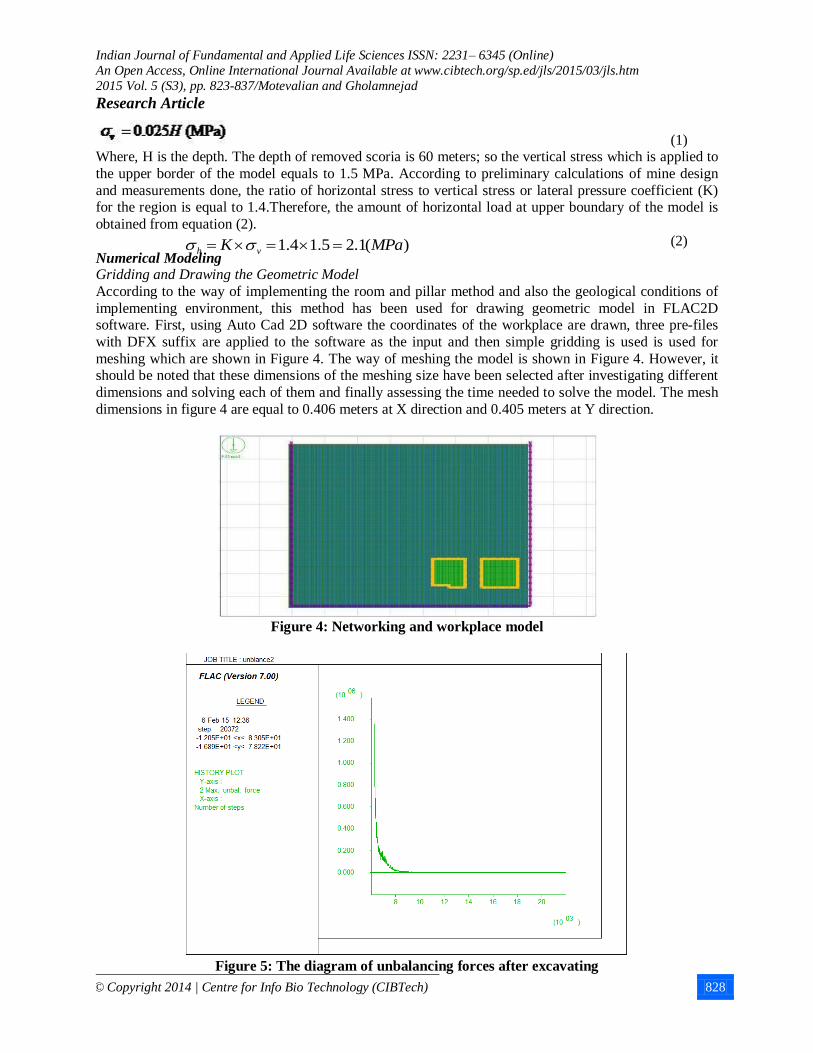
Numerical Modeling Gridding and Drawing the Geometric Model
According to the way of implementing the room and pillar method and also the geological conditions of
implementing environment, this method has been used for drawing geometric model in FLAC2D software. First, using Auto Cad 2D software the coordinates of the workplace are drawn, three pre-files
with DFX suffix are applied to the software as the input and then simple gridding is used is used for
meshing which are shown in Figure 4. The way of meshing the model is shown in Figure 4. However, it should be noted that these dimensions of the meshing size have been selected after investigating different
dimensions and solving each of them and finally assessing the time needed to solve the model. The mesh
dimensions in figure 4 are equal to 0.406 meters at X direction and 0.405 meters at Y direction.
Figure 4: Networking and workplace model
Figure 5: The diagram of unbalancing forces after excavating
)(1.25.14.1 MPaK vh

Indian Journal of Fundamental and Applied Life Sciences ISSN: 2231– 6345 (Online)
An Open Access, Online International Journal Available at www.cibtech.org/sp.ed/jls/2015/03/jls.htm
2015 Vol. 5 (S3), pp. 823-837/Motevalian and Gholamnejad
Research Article
© Copyright 2014 | Centre for Info Bio Technology (CIBTech) 829
Solving the Excavated Model
After excavating the space needed, we solve the model to reach complete equilibrium. Lack of full
resolution of the model or prolonging it too much may mean the destruction of the block. Figure 5 shows a diagram of balancing the unbalanced forces related to model conditions after digging the corridors.
Recovery Strategy
After completion of solving the excavated model and its complete equilibration, it is time to recover the pillars. Here, the pillar recovery means the maximum withdrawal up to the roof collapse. In this method
of pillar recovery, we have acted in this way that according to the pattern in Figure 6, the cuts have been
begun from the end of workplace in the great pillar and toward the created corridor and will be continued
up to fall of workplace roof, and after the creation of each cut, the model is completely solved and the process is repeated for each cut. Considering the size of excavating equipment’s, the width of cuts will be
equal to 3 meters. Only in two cuts of 12 and 13 and due to the geometry of the site and change on the
horizon, the width of cuts is considered 3.5 m and the cuts 14 and 14 will be 2.5 m.
Figure 6: The sequence of cuts
Since there is no justification plan for the acceptable rate of recovery in the pillars in the initial design of the mine, due to same reason the pillar recovery is done with the assumption of 92 percent recovery for
the large pillar and the recovery is continued as much as possible. In Figure 6, a portion of the pillar with
4 meters in width will remain as the buffer pillar. Returning direction of recovery of pillars is marked with arrows in Figure 6.
RESULTS AND DISCUSSION
Results and Analysis Displacements Created in the Roof
At this stage, after stage by stage excavating of the cuts and solving each stage, the displacement created
in the workplace roof at each stage is investigated. The contour of roof vertical displacements after excavation is shown in Figure 7. As seen in this figure, the maximum amount of movement is created in
certain points of the roof which are known as critical points and secondary instabilities are mainly
occurred at these points. These points are marked with circles.

Indian Journal of Fundamental and Applied Life Sciences ISSN: 2231– 6345 (Online)
An Open Access, Online International Journal Available at www.cibtech.org/sp.ed/jls/2015/03/jls.htm
2015 Vol. 5 (S3), pp. 823-837/Motevalian and Gholamnejad
Research Article
© Copyright 2014 | Centre for Info Bio Technology (CIBTech) 830
First cut cut II cut III
cut IV cut V cut VI
cut VII cut VIII cut IX
cut X cut XI cut XII
cut XIII cut XIV cut XV
Figure 8: Displacement contours along the depth after various cuts

Indian Journal of Fundamental and Applied Life Sciences ISSN: 2231– 6345 (Online)
An Open Access, Online International Journal Available at www.cibtech.org/sp.ed/jls/2015/03/jls.htm
2015 Vol. 5 (S3), pp. 823-837/Motevalian and Gholamnejad
Research Article
© Copyright 2014 | Centre for Info Bio Technology (CIBTech) 831
Figure 7: Vertical displacement after the initial excavating
Figure 9: The diagram of unbalancing forces after the thirteenth cut
The contour images of roof displacements for various cuts are shown in Figure 8. After the fifteenth
cutting which is equivalent of a full withdrawal of the great pillar and the buffer pillar between rooms, the
solution process is stopped due to roof collapse. It is clear from displacements in Figure 8 and from the fifteenth cutting that before stopping the process of solving the roof has been displaced more than 4.5
meters and the roof collapse is fully determined.
Figure 9 shows the diagram of unbalancing forces after the fifteenth cut. As it is clear from this figure, the diagram of unbalanced forces in the fifteenth cut does not reach equilibrium.

Indian Journal of Fundamental and Applied Life Sciences ISSN: 2231– 6345 (Online)
An Open Access, Online International Journal Available at www.cibtech.org/sp.ed/jls/2015/03/jls.htm
2015 Vol. 5 (S3), pp. 823-837/Motevalian and Gholamnejad
Research Article
© Copyright 2014 | Centre for Info Bio Technology (CIBTech) 832
First cut cut II cut III
cut IV cut V cut VI
cut VII cut VIII cut IX
cut X cut XI cut XII
cut XIII cut XIV cut XV
Figure 10: Vertical stress contours in different cuts

Indian Journal of Fundamental and Applied Life Sciences ISSN: 2231– 6345 (Online)
An Open Access, Online International Journal Available at www.cibtech.org/sp.ed/jls/2015/03/jls.htm
2015 Vol. 5 (S3), pp. 823-837/Motevalian and Gholamnejad
Research Article
© Copyright 2014 | Centre for Info Bio Technology (CIBTech) 833
So the calculation of the recovery rate of the great pillar according to its asymmetrical geometry needs to
be simplified. For this purpose, we consider the geometry of this pillar the same in the third dimension.
Therefore, the recovery rate of the pillar for this type of strategy is obtained from equation 3 as follows:
(3)
Stress in the Workplace
Contours of vertical stress are shown in Figure 10. The results show that the withdrawal of pillars causes
the creation of the concentration of stresses at certain points that this concentration of stresses exceeds from the compressive strength of material at final cuts and causes the creation of the plastic points in the
middle pillar and parts of the roof.
In Figure 11, the displacement vectors in the workplace have been identified. As it can be seen in the figure, after the withdrawal of the great pillar the roof completely collapses.
Figure 11: The displacement vector
With regard to the movement of the roof during the recovery of pillars, the diagram of roof displacement
to cuts is shown in Figure 12 and the diagram of the maximum roof displacement to cuts is shown in
Figure 13.
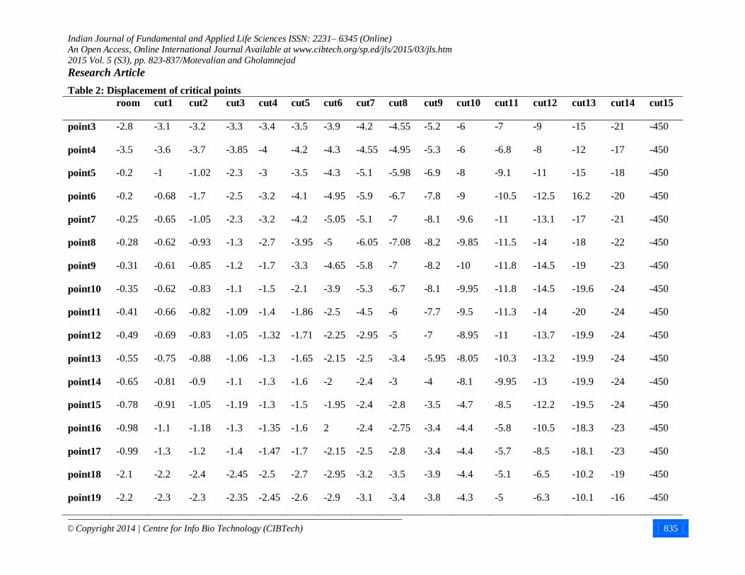
The displacement of critical points is shown in Table 2. It can be seen that the displacements after thirteenth withdrawal are immediately increased, but this increase does not cause collapse while the
withdrawal of retaining pillar between rooms causes dramatic increase in displacement and as a result the
roof collapse. In these mines, since the aim of continuation of mining is carried out as open pit mining, the collapse of the roof is necessary; otherwise the smaller pillars can be recovered using temporary
maintenance.
%32.92100323.1624993.1312547.117
323.1637993.1334547.115.32100(%)
Total
exca
A
AR

Indian Journal of Fundamental and Applied Life Sciences ISSN: 2231– 6345 (Online)
An Open Access, Online International Journal Available at www.cibtech.org/sp.ed/jls/2015/03/jls.htm
2015 Vol. 5 (S3), pp. 823-837/Motevalian and Gholamnejad
Research Article
© Copyright 2014 | Centre for Info Bio Technology (CIBTech) 834
Figure 12: The diagram of roof displacement to cuts
Figure 13: The diagram of the maximum roof displacement to cuts
0
5
10
15
20
25
30point
3
point
4
point
5
point
6
point
7
point
8
point
9
point
10
point
11
point
12
point
13
point
14
point
15
point
16
point
17
point
18
point
19
Ro
of d
isp
lace
me
nt cut1
cut7
cut13
cut14
0
50
100
150
200
250
300
350
400
450
500
cut1 cut2 cut3 cut4 cut5 cut6 cut7 cut8 cut9 cut10 cut11 cut12 cut13 cut14 cut15
Ro
of
dis
pla
cem
ent
Cuts
Indian Journal of Fundamental and Applied Life Sciences ISSN: 2231– 6345 (Online)
An Open Access, Online International Journal Available at www.cibtech.org/sp.ed/jls/2015/03/jls.htm
2015 Vol. 5 (S3), pp. 823-837/Motevalian and Gholamnejad
Research Article
© Copyright 2014 | Centre for Info Bio Technology (CIBTech) 835
Table 2: Displacement of critical points
room cut1 cut2 cut3 cut4 cut5 cut6 cut7 cut8 cut9 cut10 cut11 cut12 cut13 cut14 cut15
point3 -2.8 -3.1 -3.2 -3.3 -3.4 -3.5 -3.9 -4.2 -4.55 -5.2 -6 -7 -9 -15 -21 -450
point4 -3.5 -3.6 -3.7 -3.85 -4 -4.2 -4.3 -4.55 -4.95 -5.3 -6 -6.8 -8 -12 -17 -450
point5 -0.2 -1 -1.02 -2.3 -3 -3.5 -4.3 -5.1 -5.98 -6.9 -8 -9.1 -11 -15 -18 -450
point6 -0.2 -0.68 -1.7 -2.5 -3.2 -4.1 -4.95 -5.9 -6.7 -7.8 -9 -10.5 -12.5 16.2 -20 -450
point7 -0.25 -0.65 -1.05 -2.3 -3.2 -4.2 -5.05 -5.1 -7 -8.1 -9.6 -11 -13.1 -17 -21 -450
point8 -0.28 -0.62 -0.93 -1.3 -2.7 -3.95 -5 -6.05 -7.08 -8.2 -9.85 -11.5 -14 -18 -22 -450
point9 -0.31 -0.61 -0.85 -1.2 -1.7 -3.3 -4.65 -5.8 -7 -8.2 -10 -11.8 -14.5 -19 -23 -450
point10 -0.35 -0.62 -0.83 -1.1 -1.5 -2.1 -3.9 -5.3 -6.7 -8.1 -9.95 -11.8 -14.5 -19.6 -24 -450
point11 -0.41 -0.66 -0.82 -1.09 -1.4 -1.86 -2.5 -4.5 -6 -7.7 -9.5 -11.3 -14 -20 -24 -450
point12 -0.49 -0.69 -0.83 -1.05 -1.32 -1.71 -2.25 -2.95 -5 -7 -8.95 -11 -13.7 -19.9 -24 -450
point13 -0.55 -0.75 -0.88 -1.06 -1.3 -1.65 -2.15 -2.5 -3.4 -5.95 -8.05 -10.3 -13.2 -19.9 -24 -450
point14 -0.65 -0.81 -0.9 -1.1 -1.3 -1.6 -2 -2.4 -3 -4 -8.1 -9.95 -13 -19.9 -24 -450
point15 -0.78 -0.91 -1.05 -1.19 -1.3 -1.5 -1.95 -2.4 -2.8 -3.5 -4.7 -8.5 -12.2 -19.5 -24 -450
point16 -0.98 -1.1 -1.18 -1.3 -1.35 -1.6 2 -2.4 -2.75 -3.4 -4.4 -5.8 -10.5 -18.3 -23 -450
point17 -0.99 -1.3 -1.2 -1.4 -1.47 -1.7 -2.15 -2.5 -2.8 -3.4 -4.4 -5.7 -8.5 -18.1 -23 -450
point18 -2.1 -2.2 -2.4 -2.45 -2.5 -2.7 -2.95 -3.2 -3.5 -3.9 -4.4 -5.1 -6.5 -10.2 -19 -450
point19 -2.2 -2.3 -2.3 -2.35 -2.45 -2.6 -2.9 -3.1 -3.4 -3.8 -4.3 -5 -6.3 -10.1 -16 -450

Indian Journal of Fundamental and Applied Life Sciences ISSN: 2231– 6345 (Online)
An Open Access, Online International Journal Available at www.cibtech.org/sp.ed/jls/2015/03/jls.htm
2015 Vol. 5 (S3), pp. 823-837/Motevalian and Gholamnejad
Research Article
© Copyright 2014 | Centre for Info Bio Technology (CIBTech) 836
Conclusion
This article investigated the stability analysis and feasibility of pillar mining recovery of extraction
workplace of salt rock mining at Ghaplogh region at Khoy. As noted previously, the purpose of the present study was to achieve the highest level of pillar recovery in salt rock mining at Ghaploghup to the
final collapse of the roof of the mine. Since in room and mineral pillar method, material pillars are mainly
placed in low-value materials, waste or low grade materials, the subject of pillar recovery in these mines usually is not considered as the main issue. It is while that in Ghaplogh salt rock mine, the pillars are
inside the mineral mass and because of their special shape and size, a great part of substance is allocated
to them. On the other hand, due to the good quality of the ore in the mine, and the need to roof collapse
due to the development plan of open-pit mining for this mine, the recovery of pillars and achieving the maximum extraction of storage is felt more than ever. For this purpose, finding the model of the
workplace behavior during the recovery process, which has the best result in terms of pillar withdrawal
and also has the lowest cost, is one of this mine’s needs. As it was mentioned earlier, the recovery in mines in which workplace and pillar method is used is gradually and locally and due to accidental and
specific problems of their pillars, the common methods that are used in room and pillar cannot be used for
this method, while in the studied mine the withdrawal of pillars are done gradually and in returning form from end of workplace toward the entrance and exit doorway. The following results have been achieved
in the process of modeling for mining pillars:
1. The recovery method is gradually and in returning form; this method shows about 93 percent recovery
for the great pillar and 100 percent for retaining pillar in the studied section that we can say that the entire of the great and retaining pillars can be recovered before the roof collapse.
2. Up to before the two last withdrawals, the rate of disturbances inside the environment is to low and
large-scale displacements are less happened that its reason may be the high quality of minerals. 3. Points with critical stresses in which the stresses exceed the strength of mineral are only created in
pillars and at intersection of corridor and pillars and these points actually do not exist in pillars adjacent to
entrance and exit section and this issue provides the possibility of the exit of personnel and equipment
before the final collapse.
REFERENCES Bruhn RW and Speck RC (1984). Ground Movements Associated With Pillar Extraction Coal Mining
In Northern West Virginia. In The 25th US Symposium on Rock Mechanics (USRMS).
Chase FE, Mark C and Heasley KA (2002). Deep cover pillar extraction in the US coalfields. In Proceedings of the 21th International Conference on Ground Control in Mining, Morgantown, West
Virginia University, USA 69-80.
Congliang L, Tan Z, Deng K and Li P (2013). Synergistic instability of coal pillar and roof system and filling method based on plate model. International Journal of Mining Science and Technology.
Dehghan S, Shahriar K, Maarefvand P and Goshtasbi K (2013). 3-D numerical modeling of Domino
failure of hard rock pillars in Fetr6 Chromite Mine, Iran, and comparison with empirical methods. Journal
of Central South University 20(2) 541-549. Ghasemi E and Shahriar K (2012). A new coal pillars design method in order to enhance safety of the
retreat mining in room and pillar mines. Safety Science 50(3) 579-585.
Ghasemi E, Ataei M, Shahriar K, Sereshki F, Jalali SE and Ramazanzadeh A (2012). Assessment of roof fall risk during retreat mining in room and pillar coal mines. International Journal of Rock
Mechanics and Mining Sciences 54 80-89.
Ghasemi E, Shahriar K and Sharifzadeh M (2010). A new method for risk assessment of pillar
recovery operation. Safety Science 48(10) 1304-1312. Lane WL, Yanske TR and Roberts DP (1999). Pillar extraction and rock mechanics at the Doe Run
Company in Missouri 1991 to 1999. In Proceedings of the 37th US Rock Mechanics Symposium
(Rotterdam: Balkema) 285-292. Mark C and Chase FE (1997). Analysis of retreat mining pillar stability (ARMPS). In: Proceedings-
New Technology for Ground Control in Retreat Mining, Pittsburgh, PA: US Department of Health and

Indian Journal of Fundamental and Applied Life Sciences ISSN: 2231– 6345 (Online)
An Open Access, Online International Journal Available at www.cibtech.org/sp.ed/jls/2015/03/jls.htm
2015 Vol. 5 (S3), pp. 823-837/Motevalian and Gholamnejad
Research Article
© Copyright 2014 | Centre for Info Bio Technology (CIBTech) 837
Human Services, Public Health Service, Centers for Disease Control and Prevention, National Institute
for Occupational Safety and Health, DHHS (NIOSH) Publication No. 97-122 17-34.
Mark C and Chase FE (1997). Analysis of retreat mining pillar stability (ARMPS). In: Proceedings-New Technology for Ground Control in Retreat Mining, Pittsburgh, PA: US Department of Health and
Human Services, Public Health Service, Centers for Disease Control and Prevention, National Institute
for Occupational Safety and Health, DHHS (NIOSH) Publication No. 97-122 17-34. Mark C and Zelanko JC (2001). Sizing of final stumps for safer pillar extraction. In: Proceedings of the
20th International Conference on Ground Control in Mining, Morgantown, WV 59-66.
Mark C and Zelanko JC (2005). Reducing roof fall accidents on retreat mining sections. Coal Age
110(12). Mark C, Chase F and Pappas D (2003). Reducing the risk of ground falls during pillar recovery.
Transactions-Society for Mining Metallurgy and Exploration Incorporated 314 153-160.
Mark C, Karabin G, Zelanko JC, Hoch MT and Chase F (2002). Evaluation of pillar recovery in southern West Virginia. R & P 3(21.13) 19-09.
Pereira SP, Costa JFCL, Salvadoretti P and Koppe J (2012). Mining simulation for room and pillar
coal operation. Journal of the Southern African Institute of Mining and Metallurgy 112(6) 473-476. ZipfJr RK and Mark C (1997). Design methods to control violent pillar failures in room-and-pillar
mines. Transactions of the Institution of Mining and Metallurgy-Section A-Mining Industry 106 A124.