mdg 1005 manual on pillar extraction in nsw underground coal
TRANSCRIPT

--
SPLIT
Figure 7.1a
BEAM
WEIGHT
- --"t,- ............
,,I
B A
I •
•
STABLE FENDER
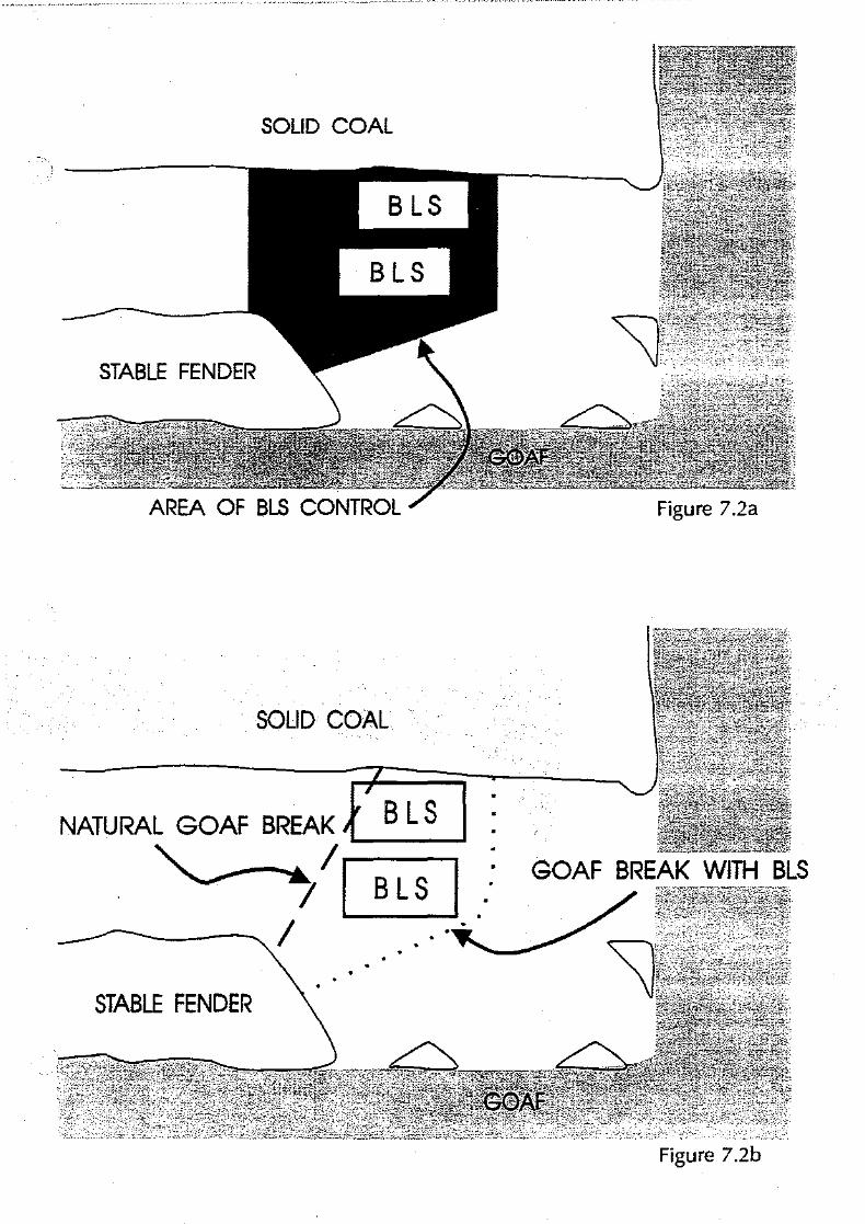
SOLID COAL
B LS
STABLE FENDER
AREA OF BLS CONTROL Figure 7.2a
· SOLID COAL
NATURAL GOAF BREAK B l S GOAF BREAK WITH BLS~/~:
Figure 7.2b
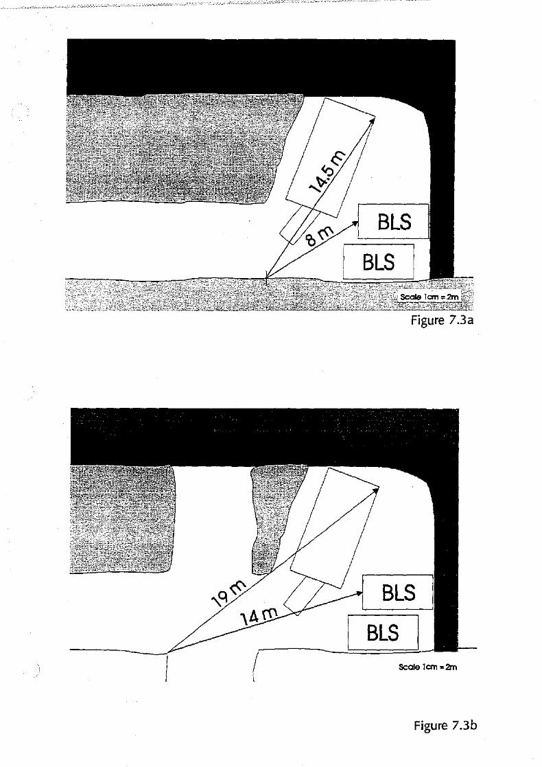
BLS
Figure 7.3a
BLS
BLS Scale 1an =2m
Figure 7.3b

· ~ ~'-'~-..·.. _.. •.
, 6m
Figure 7.4
' \
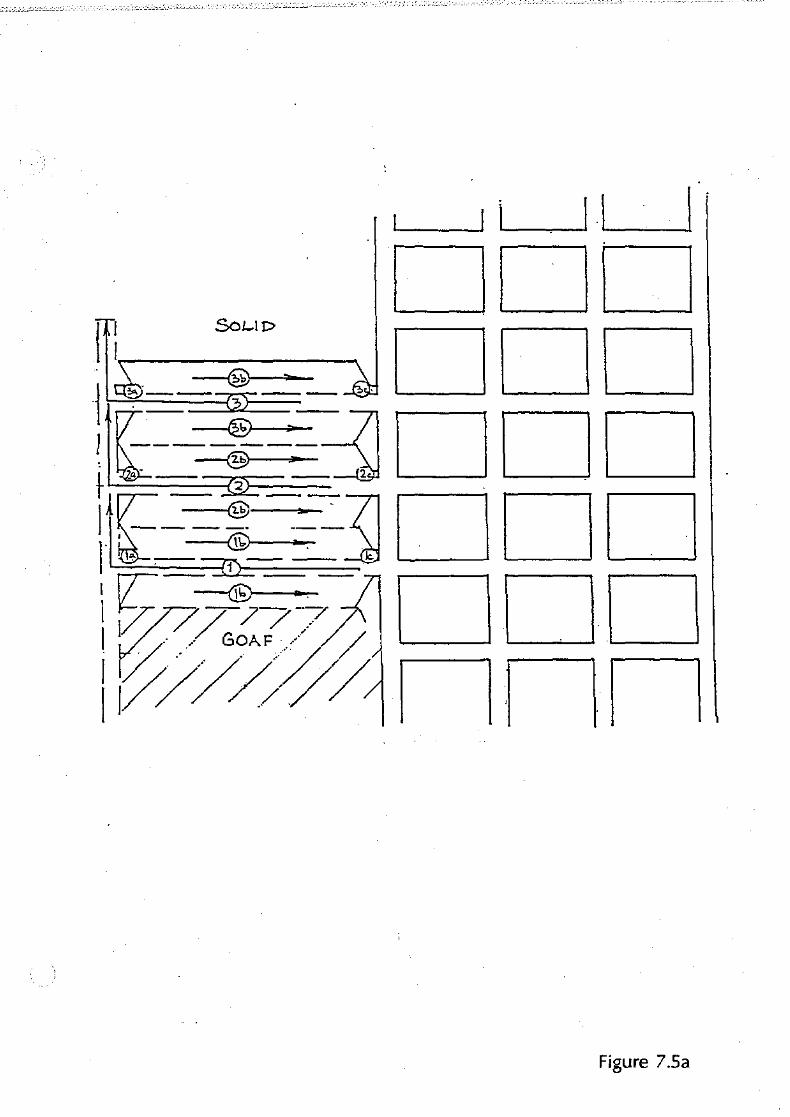
Figure 7.5a

SOUDSIDE
\ \~ [jE]
2.0 1:: fB!liDll
-,- L!.!__j~ 2.0m
BLSc -~ n _lU
II GOAFSIDE
SOUDSIDE
\\\CJ
Figure 7.5b
GOAFSIDE
Figure 7.5c

STOOK TO BE LEFT
Figure 7.5d

a.Om
5.5m
Figure 7.6

I /
I
i:_ \!: ~
'I'
> ~
.. I.....
Figure 7.7

Figure 7.8

CHAPTERS
CASE STUDIES
8.1 INTRODUCTION
In this chapter case studies are presented on accidents that have occurred recently in New South Wales underground coal mines.
In cases 1 - 4 site data and a brief history are provided for background information. Then, from Chapter 2, relevant design issues (both positive and negative) are discussed. It is important to note that whilst issues vary from case to case, at least four are relevant in any particular accident.
Cases 5 - 6 are presented to highlight the importance of maintaining effective control over extraction operations as outlined in Chapter 5.
8.2 CASE HISTORIES
Legend
w width ofpanel (m) H depth ofseam from surface (m) w width ofpillar, fender, stook (m) h extracted seam height (m)
CASE I
SITE DATA
H- 140m W- 140m h - 2.4m
Roof Strata - 30m Conglomerate Floor Strata - 2m Claystone
BRIEF HISTORY
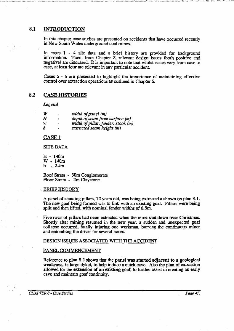
A panel of standing pillars, 12 years old, was being extracted a shown on plan 8.1. The new goaf being formed was to link with an existing goaf. Pillars were being split and then lifted, with nominal fender widths of 6.5m.
Five rows of pillars had been extracted when the mine shut down over Christmas. Shortly after mining resumed in the new year, a sudden and unexpected goaf collapse occurred, fatally injuring one workman, burying the continuous miner and entombing the driver for several hours.
DESIGN ISSUES AS SOCIA TED WITH THE ACCIDENT
PANELCO~NCEMENT
Reference to plan 8.2 shows that the panel was started adjacent to a geological weakness, (a large dyke), to help induce a quick cave. Also the plan of extraction allowed for the extension of an existing goaf, to further assist in creating an early cave and maintain goaf continuity.
CHAPTER 8- Case Studies Page47.

COAL LEFI' IN THE GOAF
Due to poor floor conditions, as well as several seam rolls, numerous large stooks and sub pillars were left in the goaf. This coal delayed caving.
On the solid barrier side of the panel, between 23 and 25 cut-through whole pillars were abandoned. In addition to delaying caving these pillars reduced the panel width and may have interrupted normal goaf formation.
On the old goaf side of the panel, considerable amounts of coal had been left adjacent to the dyke. This coal effectively prevented the two goaves from
. . linking together. (It is also believed that more coal was actually left in the old goaf than shown on the plan).
The overall result was that the goaf being formed did "hang up" and then fell in thin sheets, only 3m thick. Windblasts sometimes resulted from these shallow falls.
EXTRACTION WIDTH
As a result of the factors mentioned above the effective panel Wtu ratio was 1, a critical width for caving. This figure resulted in the potential for unpredictable goafformation.
PRE - SPLmiNG
Plan 8.2 indicates that the row of pillars at the goaf edge was pre - split across the full width of the panel, thus the size of pillar cores was markedly reduced. This loss of core led to greater pillar compression, more strata movement and thus a reduction in strata integrity at the goaf edge.
Rib crush shown on plan 8.3 was caused by pillar compression and roadway strata movement (i.e. floor heave).
CONTINUITY OF EXTRACTION
The shutdown of operations over Christmas resulted in a 3 week break in · production. Time dependent behaviour of the goaf edge pillars and roadways further reduced strata integrity at the goaf edge.
The 12 year old pillars and roadways, due to time dependent behaviour, had already deteriorated since first mined. Remedial support especially at to intersections was required.
OTHER ISSUES
RELIABILITY OF EXISTING PLANS
There was some doubt that the plans of adjacent goaf areas accurately reflected the amount of coal left in the goaf.
CHAPTER 8- Case Studies Page48.

IDUSTINGPrrLARANDROADWAYLAYOurn
Whilst plan 8.3 appears to show a regular pillar layout, in fact there were variation in pillar dimensions, intersection size and roadway widths. An accurate plan is essential for careful design and controlled extraction.
SUMMARY OFISSUES
Favourable Adverse
- commencing near a dyke - excessive coal;(: in goaf - extension ofan existing goaf - effectivepanel I H was critical
-pillar pre-splitting - time delays in production -age ofpillars - unreliable plans
CASE2
SITE DATA
H - 140m W 60m h - 3.5m on development. An extra 2 - 2.5m of floor coal was taken on
extraction resulting in a final mining height of 5.5 - 6.0m. Total seam thickness Sm.
Roof Strata -2m Coal, 1.5m Shale, lOrn plus Conglomerate and Sandstone. Floor Strata - Shale.
BRIEF HISTORY
The pillars being recovered, shown on plan 8.4, where over 60 years old. To control spontaneous combustion the goaf being formed was kept separate from old adjacent goaves. This.separation was achieved on one side by a solid barrier and on the other by a double row of seals.
Pillars were recovered by splitting, and then sequentially mining the fender and ramping the floor to recover bottom coal. Where possible an extra pillar was formed in the solid barrier to a height of 5.5 - 6.0m.
Shortly after production re-commenced, following a Christmas shutdown, the final stook in a fender (stook X) suddenly collapsed fatally injuring one workman and burying the continuous miner and shuttle car.
DESIGN ISSUES ASSOCIATED WITH THE ACCIDENT
CONTINUITY OF EXTRACTION
The break in production over Christmas left the goaf and it's relatively high pillar edge (5.5 - 6.0m) under load for 3 weeks. Time dependent behaviour of the these pillars reduced strata integrity at the goaf edge.
CHAPTER 8- Case Studies Page49.

The 60 year old pillars and roadways, due to time dependent behaviour had already deteriorated since first mined. (Tests conducted after the accident showed bed separation in the roof, especially at the shale/conglomerate interface, had occurred outbye the face).
EXTRACTION WIDTH
The effective panel WJH ratio was 0.45, a subcritical width for caving. This ratio helps explain why the coal left in the goaf had little impact on caving or goaf edge loads. Load was able to be transferred to the adjacent barriers and the conglomerate could span the 60m of goaf without massive failure. Only the coal/shale tops collapsed into the goaf.
The height of the fenders and stooks left in the goaf, i.e. 5.5 - 6.0m further helped to reduce their strength (refer to section 1.2.9). w/h ratios for stooks and fenders were generally less than 1.
GOAF EDGE STRAIGHTNESS
Formation of the pillar (5.5 - 6.0m high) in the barrier, adjacent and prior to, the extraction of the roadway pillar, as shown on plan 8.5 effectively resulted in stook X having goaf on 3 sides. The security of the continuous miner whilst extracting the fender was dependent on a stable stook X.
TAKING BOTTOM COAL
Removing bottom coal reduced the WJh ratio of stook X to less than 1. Further the activity of removing bottom coal increased the length of time workman were at any one place, therefore increasing their exposure to potential hazards.
SUMMARY OFISSUES
Favourable Adverse
-sub-critical panel WJH - low strength stooks left in goaj
- age ofpillars - time delays in production -goajon 3 sides
- taldng bottom coal
CASE3
SITE DATA
H - 130m W - variable from 120 - 160m within panel. h - 2.8m
Roof Strata - 30m Conglomerate. Floor Strata - 3m Claystone.
CHAPTER 8- Case Studies Page 50.

BRIEF HISTORY
Pillar extraction using a long split and fender method was being practiced as shown on plan 8.6. The f!I'St three panels in the block being mined, were regular in shape but a large fault meant the final panel would be triangular. Plans 8. 7 and 8.8 show the extraction layout.
From the outset of extraction caving had been poor. At least 20m of goaf was standing prior to the accident. Whilst driving a long split to hole the previous panel goaf, brattice timber was constantly being dislodged by heavy rib spall. A ventilation window was driven through the fender. As soon as the long split was re-commenced on enormous "bump" occurred tearing away the roof and coal ribs, fatally injuring one workman ..
DESIGN ISSUES ASSOCIATED WITH THE ACCIDENT
PANELCO~NCEMENT
The panel started adjacent to a fault to help induce a quick cave. Extraction allowed for the extension of an existing goaf, to further assist in creating an early cave and maintain goaf continuity.
LIFTING LEFT AND RIGHT
Extraction provided for lifting on both sides of the original three aecess roadways, see plan 8.7. To achieve this a sub pillar 6m x lim was left where the two extraction directions meet.
COAL LEFT IN THE GOAF
The effect of the 6m x 11m sub pillar plus other stooks and sub pillars left (but not shown), delayed caving. The 16m x lOrn chain pillars left against the previous panel goaf, delayed the linking of these goaves.
PANEL UNIFORMITY
Irregular panel width, created by retreating on a decreasing front, sometimes leads to inconsistent or unpredictable goaf formation. The layout adopted
. probably concentrated stress levels at the goaf edge above that normally expected. ·
FENDERS
The fender width between the face road and the goaf was Urn with a Wfh of 4. This fender, although heavily loaded did not collapse when the event occurred. It continued to protect the face road.
CHAPTER 8- Case Studies Page 51.

OTHER ISSUES
VENTILATION HOLING
Driving of this hole weakened the fender at that point and formed a 3 - way intersection. The subsequent roof collapse occurred in this intersection and nowhere else along the long split.
SUMMARY OFISSUES
Favourable Adverse
-commencing near a fault -lifting both sides ofpanel access -extension ofan existing goaj -stable fender
- excessive coal left in goaj - irregular pane/layout - ventilation holing
CASE4
SITE DATA
H - 22m w 200m h - 2.1- 2.3m
Roof Strata - 4m of course grained Sandstone, then interbedded Sandstone, Siltstone and Mudstone.
Floor Strata - Sandstone.
BRIEF IDSTORY
40 year old pillars, of varying dimension were being extracted. Refer to plan 8.9. Nominal fender widths were 6m. Roadway widths varied from 5 - 7m, averaging 6m.
Extraction had proceeded to the point shown on plan 8.9. Significant sub-pillars had been left in the goaf. Approximately 40m by 40m of goaf was standing immediately adjacent to the face. Whilst the second lift from a fender was being taken the goaf collapsed, riding over the fender fatally injuring three workmen, entombing two others and burying the continuous miner.
DESIGN ISSUES ASSOCIATED WITH THE ACCIDENT
. GOAF EDGE STRAIGHTNESS
Extraction had developed to a point where the face operations were SWTOunded by goaf on three sides. Elevated loads were present on the goaf edge. ·
CHAPTER 8- Case Studies Page 52.

SHALLOW COVER
The risk of uncontrolled goaf collapses is considerably increased by shallow cover. Once a goaf has been formed regular caving should be maintained. Section 1.2. 7 further outlines the impact of shallow cover on caving.
COAL LEFf IN THE GOAF
For various reasons large amounts of coal were left in the goaf. These sub pillars and stooks definitely delayed caving. At shallow depths, even relatively small stooks can slow caving.
FENDERS
The fender at the face collapsed. Its height had been reduced by O.Sm after the fall. The fender width was variable from 3 • 4m. This results in Wfh ratios of 1.4 • 1.8. Suggested minimum fender width are Sm, or a Wfh of least 2, whichever is the greater.
SUMMARY OFISSUES
Favourable Adverse
None -goafon 3 sides -shallow cover - excessive coal/eft in goaf - low strength fender
In cases 5 and 6 maintenance of control over the operation failed. Despite good design, poor decisions by individuals resulted in tragic events. Tight management control and supervision is essential for safety at the goaf edge.
CASE5
In the accident shown on plan 8.10 one workman was fatally injured and the continuous miner buried.
Relevant factors were:
- A decision to vary the sequence of extraction from lifting one side of the split to lifting both sides ofthe split.
- Failure to specify how the fenders were to be extracted in a controlled fashion.
CASE6
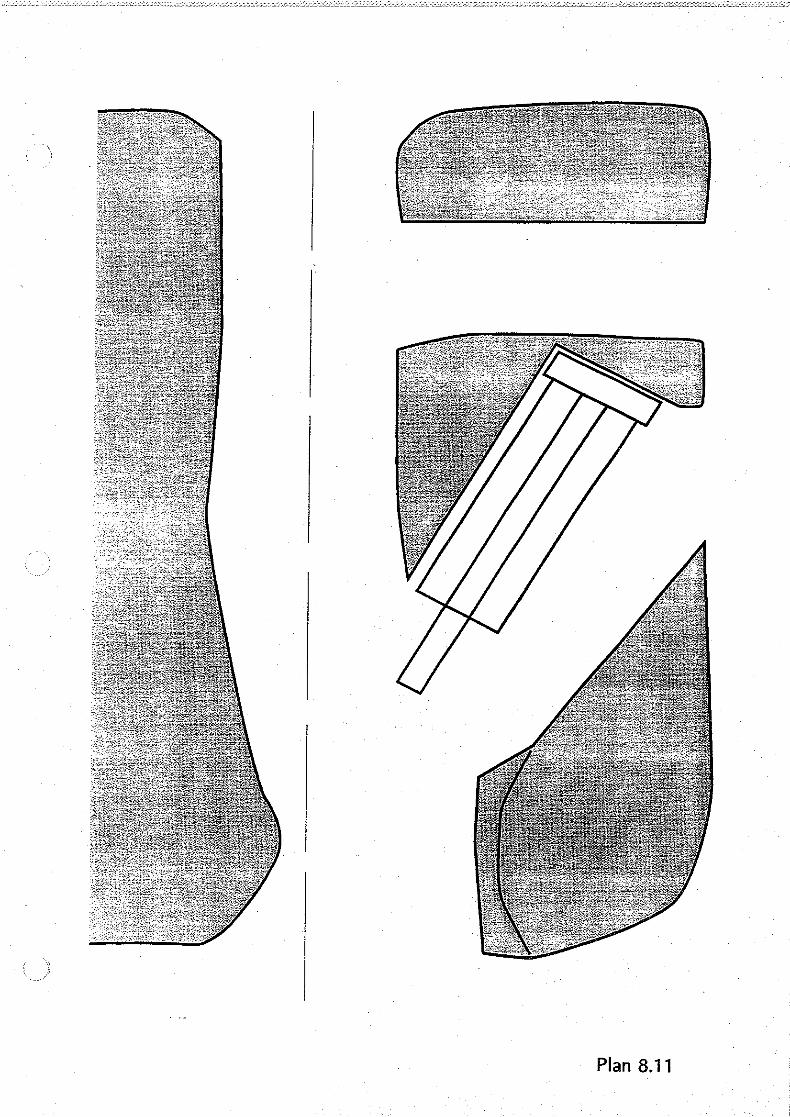
In the accident shown on plan 8.11 one workman was fatally injured and the continuous miner buried.
Relevant factors were:
• An unwarranted and unauthorised variation to the approved plan.
CHAPTER 8 - Case Studies Page 53.
'
LOCATION OF ACCIDENT
Plan 8.1

Plan 8.2

:0
J ~ ==Q
~ ~ E HDG
J ~-:20·5-----.l!l:
F HDG
J GHOG
-o 0 Vl :::; 5:z
,.., :0 c Vl :I:
2N
:0
,; ; ._ :..;..:->.;:.~.::-:
Plan 8.3

- -
'... "j
---r --~ -,1 --- ··I
--] --~ I
---- ()
--··10 .. --ru
-'--!." I r-lf-viE\1 - ,, ---
.··]-. ··-:"U
--~~ ,- · 0 t/) .• · . -{.g<:
"'· - ~ --] v• :I:
I
- I ·\---
-·-,. I -·'
f ..... , ....,

• ~LOCATION OF - NEXT TOJOY15S.C:
·-r A ~34;-·HEADIN·~·-·-~ LIP OF FALL '\
PLAN VIEW ·OF WORKING AREA WHERE FATAL ACCIDENT· OCCURRED
REDUCTION RATIO 1:400
"'0 w :J NOTE AREA HEAVILY BOLTED AND PROPPED ~ FOR . SUPPORT .Vl .
·:
.•'
SECTION "C-'C" SHOWING LIP
AREP,, MACHINES AND EXT'ENf OF FI~LL
REDUCTION RATIO 1: 100
STONE AND SHALE
(/ ---'t :J
COAL AND SHALE
~///////////////
t
t;
[.j
' I>
::·
i">
!;:,. :·: f~ ::i;.. '1.':
L

Plan 8.6

I .I
\ \
''
. ·'-
·, \ \ .).. ~ ~
\ . ,_- --.
Plan 8.7

0
0 0
0
6·0m
0 111m o
0 0
0 0
0
-r
' 'I-- 0
0 0
0
- .,
'I
0
' o . o tx:].____.i___-:-_o· o
0
0
0
0
0 0
3:,..., -f ::c 0 0
.,0
ITI X -f ::0 > n -f z Cl ., ITI z 0 m ::0 Vl
0
0
co. .., ,.., ::: C\,......., rt> z .., 0 ""0.., 0
"0
0
0
o
Plan 8.8