specification for the electrical installation for …
TRANSCRIPT

19034 – Umalusi Existing Offices Additions and Alterations: Sub-Contract June 2020 Electrical Installation Revision 0 19034_ESP003 - Project Specification
SPECIFICATION FOR THE ELECTRICAL INSTALLATION FOR
UMALUSI EXISTING OFFICES ADDITIONS AND ALTERATIONS: SUB CONTRACT
PROJECT SPECIFICATION
I N D E X 1) General Description and Extent of Work 3/1
2) Division of Work 3/1
3) Contract Drawings 3/2
4) Cost Variations 3/2
5) Testing, Setting and Commissioning 3/3
6) Approvals 3/4
7) Guarantees 3/4
8) Standards 3/5
9) Materials and Equipment 3/5
10) Equipment Delivery 3/5
11) Drawings, Samples and Operating Manuals 3/5
12) Training 3/8
13) Registered Personnel 3/8
14) Service Conditions 3/8
15) Electrical Supply System 3/9
16) Electricity Supply Authority 3/9
17) Earthing 3/9
18) Bonding 3/10
19) Lightning Protection 3/11
20) Surge Protection 3/11
21) Low Voltage Distribution Boards & Motor Control Centre 3/12
22) Cabling and Busbars 3/23
23) Cable Trays and Ladders 3/27
24) Conduit and Wiring Channels 3/29
25) Wiring Installation 3/36
26) Luminaires 3/39

19034 – Umalusi Existing Offices Additions and Alterations: Sub-Contract June 2020 Electrical Installation Revision 0 19034_ESP003 - Project Specification
27) Terminal Devices 3/43
28) Connections to Equipment 3/46 29) Cabling and Wireways 3/50
30) Diesel Generators 3/56
31) UPS 3/65
32) Services Interface Testing 3/74

19034 – Umalusi Existing Offices Additions and Alterations: Sub-Contract June 2020 Electrical Installation Revision 0 19034_ESP003 - Project Specification 3/1
PROJECT SPECIFICATION
1. General Description and Extent of Work
The sub contract works covered by this document consists of the supply and installation of everything necessary for the satisfactory completion of the electrical installation for the Retrofit. The work includes inter alia for the supply and installation of cabling, conduits, wiring, cabling, powerskirting, switch socket outlets, light switches, isolators, distribution boards, internal and external luminaries and wireways for security, telephone, smoke detection, PA and information technology. This electrical work consists inter alia of the following; 1.1 Stripping of the existing installation as detailed in the bill of quantities.
1.2 Retubing, rewiring and reinstalling the new installation as shown on the drawings. 1.3 Providing wireways for telephone, data, access control and CCTV.
1.4 Installation of generators, UPS systems and distribution boards as specified. 1.5 IT, Electronic Security / Access Control & CCTV containments only 1.6 Testing and commissioning.
1.7 As Built Handover Documentation
This work is to be done in accordance with the contractor's installation programme and relevant division of work between trades as detailed elsewhere in this document. It should be noted that the installation is to be carried out in accordance with the OSH Act.
2. Division of Work
2.1 Principal Building Contractor (PBC) The Contractor will be responsible for providing the PBC with drawings indicating builders
work requirements. Including but not limited to penetrations, plinths, co-ordination of supply points
2.2 Electrical Sub-Contractor (Contractor)
The extent of the work to be undertaken by the Electrical Contractor as part of this
contract is shown on the contract drawings and listed in the Bills of Quantities for pricing.
2.3 Plumbing Sub-Contractor Hot water cylinders/boilers will be provided, installed and connected up, mechanically and
electrically by the Plumbing Sub-Contractor. The Contractor will bring an electricity supply to a position agreed with the PBC and terminate this supply in the isolator specified. The Plumbing Sub-Contractor’s electrician will be responsible for connecting up and wiring between isolator and hot water boiler.
The Contractor will be responsible for earthing hot and cold water piping and for all cross-
bonding of the plumbing system. The Contractor is not responsible for the control and/or protection of the hot water cylinders/boilers.

19034 – Umalusi Existing Offices Additions and Alterations: Sub-Contract June 2020 Electrical Installation Revision 0 19034_ESP003 - Project Specification 3/2
2.4 Mechanical Sub-Contractor HVAC equipment will be provided, installed and connected up, mechanically and
electrically by the Mechanical Sub-Contractor. The Contractor will bring an electricity supply to a position agreed with the PBC and terminate this supply in the isolator specified. The Mechanical Sub-Contractor will be responsible for connecting up and wiring between isolator and equipment.
The Contractor will be responsible for the installation of cast-in / built in wireways to a
position agreed with the PBC, for the installation of control wiring by the Mechanical SUB-Contractor.
The Contractor will be responsible for earthing and for all crossbonding of the mechanical
system. The Contractor is not responsible for the control and/or protection of the HVAC equipment.
3. Contract Drawings The tender drawings will become the contract drawings and will be revised, amplified and extended as necessary and in accordance with the development of the Architect's design.
The Sub-Contractor shall price for monitoring the Architect's and Structural Engineer’s drawings as issued to site, monitoring changes such as locations and swings of doors, windows, wall penetrations, etc. and for locating the electrical outlets and the installation generally to suit, as well as for informing the Engineer.
4. Cost Variations
Upon general revisions of an electrical drawing the relevant cost implications will be calculated, using the rates included in the Bill of Quantities. Where there are no Bills of Quantities rates the calculation will be based on rates generally applicable to the industry which will become the agreed “non scheduled item” rates. Scope of work changes will be calculated using rates included in the Bills of Quantities and the agreed “non scheduled item” rates. The cost of the remeasured work and scope of work changes is to be agreed no a monthly basis. Variation Order No. 1 will be an omit of all contingency and provisional items.
Should the Contractor not agree with the rates of any non scheduled items or with the re-measurement quantities produced by the Engineer, he is required to advise the Engineer accordingly, within 2 (two) weeks of the date shown on the drawings and/or variation order, and to provide substantiation for the pricing revisions he requires, and the relevant costing details.
Under no circumstances will variation pricing be re-calculated at the request of the Contractor, after the 2 (two) weeks time period has expired.
Where it is imperative that the Contractor takes instructions from persons other than the Engineer, and acts immediately in the interests of the Employer to avoid abortive work or fruitless expenditure, it is mandatory for him to advise the Engineer telephonically of the cost implications, preferably before proceeding with the work but, at latest, within 24 (twenty four) hours of commencing the change. Failure to observe the foregoing (whether the instruction is given verbally or in writing) will result in the Contractor being held responsible for the cost of the variation work.
5. Testing, Setting and Commissioning

19034 – Umalusi Existing Offices Additions and Alterations: Sub-Contract June 2020 Electrical Installation Revision 0 19034_ESP003 - Project Specification 3/3
The Contractor shall perform comprehensive quality control, pre-testing, testing, pre-commissioning and commissioning on all electrical systems in a systematic manner and in exact accordance with CIBSE Commissioning Codes, as follows;
• CIBSE Code C – Automatic Controls; • CIBSE Code L – Lighting; • CIBSE Code M – Management;
On completion of the project, the Contractor shall submit a typed commissioning report demonstrating that the services were commissioned in accordance with the CIBSE Commissioning Codes. The commissioning report shall include comprehensive records (dated and signed) of quality control, pre-testing, testing, pre-commissioning and commissioning on all electrical systems. The report shall include any requirements for future seasonal testing, a list of any outstanding issues, a list of changes made to the building as a result of the commissioning process, and a list of any recommended changes that should be made in the future. The commissioning report is to be included in the O&M documentation. Except where otherwise provided in the contract documents, the Contractor shall provide :
a) A test schedule for each section of the works, system or item of equipment/plant to be tested, giving the time, date and place of the test, detailing the method statements and test procedure, the type and number of tests to be carried out, and the type, make and serial numbers of all test instruments that will be used.
b) All labour, materials, power, fuel, accessories and properly calibrated instruments
necessary for carrying out the tests. c) Health and Safety risk assessments and method statements for the tasks to be
completed. The Contractor shall give 14 (fourteen) days notice, in writing, when any portion of the installation or plant is ready for testing. In the event of the plant or installation not passing the tests, the Employer shall be at liberty to deduct from the contract price, any reasonable expenses incurred in repeating the tests. The Contractor shall carry out preliminary tests necessary to satisfy himself that the plant, materials and equipment comply with the provisions of the contract and are in a suitable state to satisfy the requirements of the Specification. The Contractor is required to record these preliminary test results (in a manner to be agreed with the Engineer), and to submit one typed copy to the Engineer for comment, prior to the Engineer attending the acceptance tests. If the Contractor fails to undertake the acceptance tests within a reasonable period of time, the Employer may arrange to have the tests performed by another party. All tests so made shall be at the risk and expense of the Contractor. The drawings and specifications contain details of any specific equipment, tests and setting requirements. In general, however, the following should be regarded as a minimum requirement :
a) Each circuit shall be checked for insulation resistance to earth and between phases and
neutral, using a hand-cranked 500 volt megger.
b) The earth loop resistance and circuit resistance of each circuit shall be checked, using a null balance megger or earth loop tester.
c) The main earth system resistance shall be verified, using a hand- cranked null balance
megger.

19034 – Umalusi Existing Offices Additions and Alterations: Sub-Contract June 2020 Electrical Installation Revision 0 19034_ESP003 - Project Specification 3/4
d) The on load volt drop and load balancing of all circuits and distribution boards shall be verified.
e) The earthing of all water and waste pipes shall be verified, using a null balance megger.
f) The lighting level in all areas shall be measured, using a suitable digital instrument. g) The value at which all earth leakage units trip when tested at each outlet position in turn,
shall be measured. It is a requirement of this contract that the Contractor undertake all the above tests and submit the results in typed format on the test report (1 per distribution board) to the Engineer. The test report is to be attached to the certificate of compliance. The Engineer will subsequently request the Contractor to repeat all, or part, of these tests, during the final inspection prior to handover. The Contractor shall set all fault protection overload devices to the prescribed settings/levels, and to list these settings in the as built drawings and manuals.
6. Approvals
The drawings, documents and specification indicate the type, size and make of equipment, materials and components required.
The Contractor will be required to supply, strictly in accordance with these requirements, unless otherwise approved by the Engineer.
Approval, in all instances, shall be taken as formal approval, in writing, by the Engineer. Verbal approval will not be recognized and the Contractor will be held responsible for any subsequent costs or fruitless expenditure involved.
7. Guarantees
The Contractor shall provide a twelve-month guarantee of all labour, materials and equipment supplied in terms of this contract.
The guarantee period shall commence from the date of practical completion of the whole project in terms of the Principal Building Agreement.
During the guarantee period, the Contractor will maintain, without charge, all equipment supplied under this contract and, not withstanding anything to the contrary, shall replace all components that fail, free of charge.
The guarantee is deemed to cover all items of equipment and materials, such as control fuses, lamps, starters, ballasts gauges, switches, relays etc. In the case of power fuses, the Contractor will only be required to replace these items free of charge where failure has occurred due to an inherent or latent defect in the installation.
When purchasing materials and equipment from suppliers, the Contractor shall obtain formal cessions of all guarantees covering the materials and equipment, from the supplier, in favour of the Employer. The Contractor should, therefore qualify all orders accordingly.
Where the Contractor is responsible for supplying transformers, distribution boards, M.V. switchgear etc. etc., be shall take ultimate responsibility for the guarantee of this equipment.
The Contractor will also be responsible for the guarantee of all components and equipment specified by name in the documents or as otherwise approved by the Engineer.
In the event of the Contractor objecting to certain types of equipment, component, manufacturer, or otherwise, this shall be stated at the time of tendering. The Contractor shall also indicate at

19034 – Umalusi Existing Offices Additions and Alterations: Sub-Contract June 2020 Electrical Installation Revision 0 19034_ESP003 - Project Specification 3/5
least two alternatives that are acceptable generally and in terms of the 12 months guarantee requirement.
During the guarantee period, the Contractor will be contacted directly in regard to complaints or failures and shall in turn contact and direct the relevant supplier/manufacturer or his own staff, irrespective of whose ultimate responsibility it shall be to correct the situation.
8. Standards
The latest editions and/or amendments of the following Standards and Codes of Practice are applicable:
a) The South African National Standard (S.A.N.S.) Specifications, as applicable to this
contract. b) The Occupational Health and Safety Act, (Act 85 of 1993) as amended. c) The latest edition of the S.A.N.S. 10142 Code of Practice for the Wiring of Premises d) I.E.C. Standard Specifications and Codes of Practice, where the S.A.N.S. and B.S.S.
equivalents are not available. e) The British Standard Specifications (B.S.S.) and Codes of Practice, where the S.A.N.S.
and I.E.C. equivalents are not available. 9. Materials and Equipment
Wherever possible, material and equipment shall be of South African manufacture and of the same make and type throughout the installation. Where materials and equipment are specified by name, make or type number, alternatives will not be considered, unless it is to the Employer's advantage.
10. Equipment Delivery
The Contractor shall place orders timeously for all materials and equipment. The responsibility for verifying delivery times of items specified rests solely with the Contractor In this regard, the Contractor's attention is directed to long lead cabling, distribution board and luminaires.
11. Drawings, Samples, and Operating Manuals 11.1 Installation and Shop Drawings & Samples
Installation and shop drawings are drawings, diagrams, illustrations, Schedules, performance charts and information brochures which are prepared by the Contractor or his suppliers, to illustrate some detailed engineering or installation aspect of the works. Samples are physical examples, provided by the Contractor or his representative and suppliers, illustrating the intended quality and type of materials, equipment and workmanship, and to establish standards by which the works will be judged. The relevant sections of the specifications indicate specific installation/shop drawing and sample requirements. The Contractor shall allow for the production of such additional drawings and information as may be necessary, from time to time, to illustrate compliance with the specifications, installations, method/procedure, or engineering aspects.

19034 – Umalusi Existing Offices Additions and Alterations: Sub-Contract June 2020 Electrical Installation Revision 0 19034_ESP003 - Project Specification 3/6
Samples and mockups will be required for all aesthetically prominent accessories or installations. The Contractor shall inspect all drawings, including structural and other services, installation, shop and design drawings, pertaining to the works, and shall make the necessary allowance in the tender price for the minor extras and omissions which might occur as the result of these final detailed co-ordinated installation and shop drawings. The Contractor shall review, stamp with his approval and submit with reasonable promptness, and in orderly sequence so as to cause no delay in the work, all drawings and samples required by the contract documents. At the time of each submission the Contractor shall inform the Engineer, in writing, of any deviation in the installation and shop drawings or samples, from the requirements of the contract documents. By submitting installation and shop drawings and samples, the Contractor thereby represents that he has determined and verified all field measurements, field construction criteria, materials, catalogue numbers and similar data, and that he has checked and coordinated each installation and shop drawing and sample, with the requirements of the works and of the contract documents. The Engineer will review drawings and samples with reasonable promptness, but only for conformance with the design concept of the project and the contract documents. The Contractor shall make any corrections required in terms of the Specification, and shall re-submit the required number of corrected copies of drawings or samples. The Contractor shall direct specific attention, in writing, on re- submitted installation and shop drawings, to revisions other than the corrections required by the Engineer on previous submissions. The Contractor shall submit drawings for review, at least 6 (six) weeks in advance of the required ordering, manufacturing or installation dates. The reviewing of drawings or samples by the engineer shall not relieve the Contractor of responsibility for any deviation from the requirement of the contract documents including compliance with program, responsibility for errors or omission in the drawings or samples, etc.
11.2 Record Drawings
Record drawings shall be maintained on a current basis as work progresses. Site inspections shall include a review of the record drawings, for the area or equipment inspected. The Contractor shall be provided with a set of prints to be kept by him on site and dimensioned by the Contractor showing the exact locations of all electrical equipment, cast or built in conduits, sleeves etc. The positions of all cables, sleeves, conduit, service routes, joints etc. shall be dimensioned on a triangular basis. Prior to commissioning and handover, the Contractor shall provide a complete set of record drawings, cross-referenced to the Operating and Maintenance Manuals where necessary, and in sufficient detail to enable the employer to carry out proper maintenance, and to facilitate subsequent alterations and additions to the system.
Drawings, Legends, Schedules, Diagrams, intended for framing and wall-mounting, shall be of the fade-free, black ink on a transparency, or photographic type.
11.3 Operation/Maintenance Manuals

19034 – Umalusi Existing Offices Additions and Alterations: Sub-Contract June 2020 Electrical Installation Revision 0 19034_ESP003 - Project Specification 3/7
The operation and maintenance manuals shall contain all information required to enable the safe and efficient operation and maintenance of all systems associated with each building. 3 Separate manuals shall be produced, one for common services, and one for each building. Prior to commissioning, the Contractor shall submit a draft copy of the indexed, loose-leaf manuals, containing complete operating and maintenance instructions for all mechanical and electrical systems specified under this contract. Manuals shall be hard covered, at least A4 in size, and must be provided with transparent plastic over-covers and reinforcing ring binders, for each page. Post commissioning and handover, the Contractor shall provide three copies of indexed, loose-leaf manuals, and electronic copy (CD/DVD) containing complete operating and maintenance instructions for all mechanical and electrical systems specified under this contract, including comprehensive testing and commissioning records.. All manuals must lie flat when open. Content shall be printed. Photocopies from product brochures will not be accepted. Only information relevant to this contract should be included The scope of content should include; Contractors and specialist suppliers contact Emergency contact details Health and safety documentation Project Systems description Modes of operation including emergency procedures and call out personnel Maintenance instructions and schedules and fault finding advice Asset register Equipment schedules Advice on disposal Software schedules and licenses Parts identification and recommended spares
Guarantee information with work/inspection/maintenance required to ensure guarantees are not nullified Manufacturer’s technical literature.
Test Certificates - Refer to “Typical Test Report” Commissioning data / report
Certificates of compliance per distribution board Statutory certification Copies of standard A4 Distribution Board Legend cards. Staff competency requirements and system training records Record drawings Modification information Note: Certificates of compliance to include the relevant Test Certificate and legend card.
11.4 Logbooks Logbooks shall be provided in each plant room, and must be at least A4 in size, typed and feint-line ruled, to provide the following columns and column headings on each page: a) Date. b) Description of Work. c) Artisan's Signature.

19034 – Umalusi Existing Offices Additions and Alterations: Sub-Contract June 2020 Electrical Installation Revision 0 19034_ESP003 - Project Specification 3/8
c) Time Spent. The logbooks shall be provided prior to commissioning and start-up of the plant, are to be kept up-to-date by the Contractor, from date of handover of the plant. All manuals and logbooks must lie flat when open.
12. Training
Prior to handover, the Contractor shall conduct comprehensive training sessions for each installed system to minimum three client representatives to enable proper running and maintenance of the installed systems. Proposed training times shall be submitted by the Contractor at least two weeks prior to the proposed date, and shall be agreed upon by both parties.
The training shall include, but not be limited to the following:
Review of Design Intent; Review of O&M Manuals; Systems set-up and configuration; Modes of Operation of the System;
Occupational Health and Safety Issues; Systems preventive maintenance and troubleshooting. Obtaining and addressing occupant satisfaction feedback.
Training sessions shall be documented and submitted with the handover documents for reference.
Separate training sessions shall be conducted and documented for each portion of works.
13. Registered Personnel
The Contractor shall have at least one installation electrician in full time employment assigned permanently to this project. The Contractor shall appoint an approved inspection authority who shall certify compliance from commencement to commissioning of the electrical installation as per the requirements of section 5.5 of the Certificate of Compliance. Proof of these aspects shall be submitted with the completed tender document.
14. Service Conditions
14.1 Normal Service : As scheduled.
14.2 Maximum ambient temp. : +40°C
14.3 Minimum ambient temp. : -5°C 14.4 Humidity : Max. Humidity: 95% 14.5 Rain fall : high in summer months, low in winter months.
14.6 Atmosphere : Semi Corrosive
All equipment and materials shall be suitable for the climatic and environmental conditions pertaining to coastal conditions.

19034 – Umalusi Existing Offices Additions and Alterations: Sub-Contract June 2020 Electrical Installation Revision 0 19034_ESP003 - Project Specification 3/9
Metalwork exposed to water, water vapour and the weather shall be stainless steel or protected against corrosion to the approval of the engineer. Contact between dissimilar metals shall be avoided. As a minimum, the following electrode potentials shall not be exceeded.
a) for connections exposed to the weather, salt water vapour or salt water, 0,25V. b) for connections of interior parts subjected to condensation but not contaminated
by salt, 0.50V.
15. Electrical Supply System
The Supply Authority Electricity Grid consists of system voltages of 132kV; 11kV; 400V 3-phase CNE and 230V single phase (50Hz)
15.1 Supply Technical Data
System Voltage : 11,000V ±10% / 400V ±10% as applicable Rated Frequency : 50Hz
Phase rotation : 3 phase, RWBR (clockwise) Design SSCC : 20kA at 11 kV
16. Electricity Supply Authority
The Contractor shall liaise with the Supply Authority to ensure that all applications to commence work are submitted, fees paid and local requirements complied with. The installation shall comply with the Supply Authority's requirements in all respects and good engineering practice.
17. Earthing
All cable containment exposed metal work is to be earthed and earths are to be continuous for the length of the run and include all bends. All circuits are to be provided with a separate earth wire as specified or as per SANS 10142 as a minimum requirement. Circuit earths and earth loop impedance must all be verified and the Engineer informed so that satisfactory operation of protection devices can be checked.
a) Earthing conductor system
The total earthing system of any electrical installation shall be in accordance with SANS 10142. Earth conductors shall be stranded copper with green PVC insulation installed on a radial arrangement from each distribution board, with no T joints or interconnection of circuits.
b) Sub-Distribution Boards
A separate earth connection shall be provided between the earth busbar in each sub-distribution board and the earth busbar in the Main LV distribution board. These connections shall consist of PVC insulated stranded copper conductors installed along the same routes as the supply cables or in the same conduit as the supply conductors.

19034 – Umalusi Existing Offices Additions and Alterations: Sub-Contract June 2020 Electrical Installation Revision 0 19034_ESP003 - Project Specification 3/10
c) Ring Mains
Common earth conductors may not be used where various circuits are installed in the same wiring channel.
d) Clean Power Earthing
Earthing for the reticulation of clean power circuits shall follow the following rules: i) All sub-distribution boards containing clean power circuits shall be provided with a
clean earth bar, completely insulated from the rest of the board and domestic earthing systems.
ii) PVC-insulated earth conductors shall be used throughout for the clean power
system. These conductors shall be fixed to the clean earth bars by means of lugs and bolts, always ensuring that the connections are completely insulated from domestic earth components.
iii) Clean power earth conductors shall always be installed in radial fashion and no
earth loops shall be formed. iv) The Contractor shall ensure that complete isolation is maintained, at all times,
between clean earth conductors and terminations, and the domestic earth system, particularly at equipment boxes and sockets.
v) The Contractor shall also ensure that connectors, plug boxes, female sockets,
etc., used for clean power circuits are adequately designed to provide complete isolation from the domestic earth system.
vi) It will be expected of the Contractor, as part of hand over procedure, to
demonstrate adequate isolation, (better than 1 Ohm), between all clean earth points and the remainder of the domestic earth system.
18. Bonding
The Contractor shall cross bond and earth all metallic services in the vicinity of electrical equipment and circuiting including hot and cold water pipes, waste and drain pipes, ceiling grids, cable trays, hand rails etc. The earth loop impedance to the furtherest point from local distribution board of all metallic services shall be checked and submitted to the Engineer for approval.
a) Steel Pipes
All steel pipes shall be connected with solid 12mm x 0.8mm perforated or solid copper strapping to the nearest distribution board. The strapping shall be fixed to the pipe work with brass nuts and bolts and against walls with brass screws at 150mm centres.
In all cases where steel pipes are positioned within 1.5m of distribution boards, an earth connection consisting of copper strapping shall be installed between the pipe work and the board. In vertical building ducts accommodating steel pipes and electrical cables, all pipes shall be earthed at each distribution board.
19 Lightning Protection
The Contractor shall arrange for the specialist lightning protection contractor to undertake a survey of the existing installation and report on the findings.

19034 – Umalusi Existing Offices Additions and Alterations: Sub-Contract June 2020 Electrical Installation Revision 0 19034_ESP003 - Project Specification 3/11
20. Surge Protection 20.1 Power Systems Protection
a) Protection against lightning: All “informal” Township and Suburban Structures” shall be protected with a 1.2/50 µS surge protection device on all phases and neutral at the building main switches at 400/230 Volts if the incoming supply is overhead within the last two kilometers of the site in Coastal regions (up to 20 km from the sea) or on all installations inland in accordance with SANS 1042-1 and IEC 61643-1. Connection method is to be Type 1 for TNS earthing systems.
b) Protection against surges: All “informal” Township and Suburban Structures”
shall be protected with 8/20µS surge protection device on all phases and neutral at the building main switch/s 400/230 Volts in accordance with SANS 10142-1 and IEC 61643-1. Connection to be Type 1 for TNS earth systems.
20.2 Electronic Systems Protection
Surge protection to electronics installation shall be supplied and installed by others.

19034 – Umalusi Existing Offices Additions and Alterations: Sub-Contract June 2020 Electrical Installation Revision 0 19034_ESP003 - Project Specification 3/12
21 L.V. Distribution Board & Motor Control Centre
21.1 Scope The specification covers all low voltage Switchgear and control gear assemblies. 21.2 Standards Requirements
Low Voltage Switchgear and Control Gear Assemblies, are to be manufactured in accordance with SANS 1473–1 (as amended), SANS IEC 60439-1 (as amended) and SANS 10142-1 (as amended) specifications. With regard to the above specification the following applies to the manufacture of the distribution boards.
21.3 Board Construction and Design
21.3.1 Construction
a) Floor standing multi cubicle type assembly/unless otherwise specified b) Stationary indoor installation
c) IP54 unless otherwise specified
d) Form 2b unless otherwise specified (Terminals in cable chamber for outgoing conductors, per functional unit, to be individually shrouded with 5 mm thick transparent polycarbonate cover)
e) Naturally ventilated
f) Physical Dimensions
1) Dimension as shown on layout drawings 2) Cable entry Top entry via a 300 mm wide cable entry
cover along the full length of the distribution board
21.3.2 Electrical Characteristics
a) Operational Voltage 400 Volts phase to phase
230 Volts phase to neutral/earth
b) Insulation Voltage 1000 Volts phase to phase 600 Volts phase to earth
c) Impulse Withstand Voltage 2 500 Volts phase to phase d) Rated short time withstand current (fault level) as shown on the single
line diagrams
e) Rated peak withstand current is to be in accordance with table 5 in SANS IEC 60439-1.
f) Cross sectional area of protective conductors with regard to thermal stresses due to current of short duration are to be based on a duration of 0.1 seconds.
g) Earthing system : TN-S Note: Rated currents of circuits and electrical equipment as shown on the
drawings

19034 – Umalusi Existing Offices Additions and Alterations: Sub-Contract June 2020 Electrical Installation Revision 0 19034_ESP003 - Project Specification 3/13
DO NOT take into account the derating of such circuits and electrical equipment due to temperature rise.
21.3.3 Environmental Conditions
a) Maximum air temperature (at any point) within the distribution board is
not to exceed 10°C above ambient of 40°C maximum and an average of 35°C over a 24 hour period.
Note: Should the heat rise within the distribution board exceed the above limits
due to the limitations of the room size etc. tenderers are to advise the anticipated heat rise in each cubicle.
b) Relative humidity – As per clause 6.12.1 in SANS IEC 60439-1. c) Pollution degree 3 applies d) Installed at sea level/inland as applicable
21.3.4 Testing a) Tenderer to advise whether distribution boards are fully type tested,
partially type tested or specially type tested assemblies. Compliance/non compliance is to be indicated.
b) Routine tests are to be carried out at the place of manufacture and
repeated on site.
21.4 General
The following general requirements are to be complied with provided they do not conflict with the above requirements. Any conflicts are to be advised by the tenderer at the time of tender.
21.4.1 Enclosures
Enclosures for distribution boards and control panels shall be wall or floor mounting as indicated, shall be engineered to accommodate the necessary equipment specified and to comply with this specification. The minimum thickness of the chassis and partition metal work shall be 1,5 mm for assemblies not exceeding 0,75 m² or 2 mm for larger panels. Thicker sheets shall be used for very large panels and where the weight of the equipment would cause buckling or vibration. Lap welding of panels and boxing of sections, is unacceptable unless specifically approved. Bolted stiffening channels and braces are acceptable. Completed sheet metal enclosures shall be free, internally and externally, from burrs, sharp edges and blemishes. A removable steel base frame shall be allowed for floor mounting boards. Removable lifting eyes shall be provided for heavy panels. All switchboard covers/doors are to be of the hinged type. Covers which have to be lifted out of position are unacceptable. Main switchboards and motor control panels are to be extendable in both directions. Unless otherwise specified, all wall mounting boards shall be front access only, and shall be manufactured in two parts :

19034 – Umalusi Existing Offices Additions and Alterations: Sub-Contract June 2020 Electrical Installation Revision 0 19034_ESP003 - Project Specification 3/14
a) a rear chassis, either built into or attached to, the supporting wall; b) an outer panel, secured to the chassis on completion of the work, and
readily removable from it. The chassis will be manufactured from zinc coated mild steel, zintex steel, other approved method of electro galvanised mild steel or 3 CR12. The chassis shall have suitable knockouts, along the top and bottom panels, for the terminations of all conduits, in not more than two rows. A feeder cable entry knockout shall also be provided, suitable for the feeder cable rating indicated on the drawings. The outer panel, secured to the chassis by means of adjustable bolts, carrying the equipment trays, the busbars and the wiring harness, is to be securely supported.
21.4.2 Painting
Tenderers are to price the following paint specification as a minimum requirement; The surface is to be prepared prior to painting by phosphatisation cleaning/degreasing treatment. The surface is then to be coated with an etching primer, followed by a base coat and an epoxy polyester powder coating to a minimum thickness of 110 µm. The colour of the finishing coats shall be decided at the time of shop and installation drawing approval. Any on site paint damage to be treated and touched up immediately.
21.4.3 Accessories
Hinges shall be of the brass lift off type. Door/cubicle catches shall be of the Barker Nelson type provided these meet the standard specification. Rear covers to be hinged and locked by electrical panel key and shall not be secured by screws or bolts. Weld-on type hinges and door locks will not be acceptable. Door opening, closing, latching and de-latching operations shall be smooth and quick, whilst ensuring proper compression of the sealing gaskets without damaging or marking the paintwork or corrosion-resistant surface of the Board. Sealing strips and gaskets shall be made of durable, non-hardening synthetic rubber or other suitable material. Care must be taken to ensure that even pressure is exerted along the entire length of the gasket, and that neither deflection nor buckling of panels occurs when the gasket is compressed. For switchboards intended for use indoors, and for external use in areas remote from the coast (100 kms), bolts, nuts and washers shall be cadmium-plated, electro-plated or galvanised. For switchboards intended for use outdoors or in coastal areas e.g. Durban area, the minimum corrosion specification for all nuts, bolts and washers shall be 316 L stainless steel. Busbar bolts must be high tensile steel type, complete with lock-nuts and lock washers. To avoid damage to the paintwork, screws, bolts, door locks, etc., must not be in direct contact with painted surfaces. The use of self-tapping screws is unacceptable. All tapped holes in metalwork shall have a minimum tapped thread length equal to the diameter of the tapped hole. All concealed/inaccessible nuts are to be of the permanently captive type. The electrogalvanised caged nut is unacceptable.
19034 – Umalusi Existing Offices Additions and Alterations: Sub-Contract June 2020 Electrical Installation Revision 0 19034_ESP003 - Project Specification 3/15
Tapped holes shall have the exposed metalwork protected against corrosion by the application of a suitable inhibitor over the tapped area, such as Tectyl or copperslip.
21.4.4 Cabling, Wiring and Busbars
The main busbars (including the neutral) shall be installed together along the top (wherever possible) of the switchboard, and along its full length. Busbars connected to C.B. stubs are to be sized and connected in accordance with the C.B. manufacturer’s requirements. All outgoing circuit breakers on main switchboards shall be connected to vertical busbar droppers with copper busbar tails. Busbar tails to be shrouded. Busbar droppers from the main busbars to be segregated from cable chamber. All outgoing circuit breakers on main switchboards shall be fitted with copper busbar tails to facilitate cable terminations in the cable chamber and not on the circuit breaker. Busbar tails shall be shrouded. Spare spaces shall be fitted with copper busbar tails (load and supply side) for future connection. Phase identification shall be Red, White, Blue, reading top to bottom, left to right, and from front to back, when facing the front face of the board. The insulation of the busbars and conductors shall not be stripped beyond the leading edge of the connection /terminal in which it has to be accommodated. Stripping shall be carried out without damage to the conductor, by means of a cable stripper. Crimping lugs and ferrules shall be used for connection into equipment not provided with screw-type compression terminals. All crimps of conductors 35 mm² and above are to be subjected to test crimps. All wiring and terminations shall be readily accessible. Under no circumstances may terminal rails be fixed to the D.B. tray or the side panels of the D.B. tray or the side panels of the D.B., or located close to live terminals, or positioned behind wiring run to equipment in the board. The wiring shall be carried out neatly, along perpendicular lines, and it shall be accommodated in enclosed wiring channels. The wiring shall not preclude the removal of, nor block the access to, any component. Insulated conductors shall not be bunched together in order to avoid heat accumulation within the core of the bunch. If bunching of conductors in unavoidable, the conductors should be de-rated in accordance with the relevant Table of the S.A.N.S. 10142 as amended, Code of Practice, control and indication for the Wiring of Premises or BS7671. Sub-distribution circuits protected by HRC fuses need only be rated for the maximum prospective asymmetrical fault level possible when the largest fusible link is installed in the fuse base. The minimum conductor area of any wiring shall not be less than 2,5 mm² and no hard drawn copper wiring is to be used within the board. All wiring is to be of the tinned, fine stranded flexible type. All wiring within boards is to be insulated. No B.C. wiring is permitted for either phase neutral or earth wiring; the earth bar being the exception. Single phase distribution boards shall be wired in red and black PVC insulated conductors.

19034 – Umalusi Existing Offices Additions and Alterations: Sub-Contract June 2020 Electrical Installation Revision 0 19034_ESP003 - Project Specification 3/16
Three phase distribution boards shall be wired in red, white and blue, black and green PVC insulated conductors. Control panels and motor contactor boards shall be wired on the power side, with red, white and blue insulated conductors. Live control wiring shall be orange. Unearthed and DC control wiring shall be grey. Neutral connections shall be black, this colour must not be used for any other connection. Earth wiring shall be insulated green, or striped green-yellow, conductors.
Cable colour coding shall be discussed with the Engineer when foreign equipment, wired to different standards, is to be incorporated in the installation.
21.4.5 General and Installation Arrangement Details
Large air circuit breakers and switch fuse units shall not be positioned at high level, unless facilities are provided to assist maintenance staff in withdrawing these units. The arrangement shall be such that sufficient space exists between adjacent items of equipment for the installation of incoming and outgoing conductors and for heat dissipation. Moulded case circuit breakers in main switchboards shall be mounted side on. The Board shall be of sufficient dimension to allow the installation of all equipment specified and any future equipment indicated on the drawings, without unduly restricting the access to, and the clearance between, the various rows. Particular attention shall be paid to the accommodation and bending of incoming and outgoing conductors within the enclosure, and the working space necessary for making off the cables, installing the lugs and connecting into the equipment. Suitable provision shall be made for vermin-proofing the cable entries and earthing the armouring. Busbar bending radii shall not be less than the minimum permissible for the thickness of busbar being used. Control/metering fuses or circuit breakers shall be base mounted on the relevant busbar. Unprotected wiring may not be run off busbars or from C.B. power terminals to remote fuses/equipment. These fuses/circuit breakers shall be easily accessible and completely safe for maintenance staff to service and repair. Ring type current transformers shall be insulated from the busbars and fixings making electrical contact with the bar must be total shrouded and locked into position with lock nuts. Current transformers around different phase may not touch each other. A minimum clearance of 50 mm is to be maintained between adjacent CT’s, and between CT's and adjacent busbars. In general, main switchboards shall be arranged such that it is possible to make off and terminate cables and install additional switches, without any risk of coming into contact with live conductors. Main switchboard panels shall be of uniform width, with not more than two size variations, i.e. 600 mm and 750 mm. Single phase sections of three phase boards shall be separated from each other. Lighting on the left-hand side and single phase power circuit on the right-hand side or lower section or top section. Three phase power circuits are to be grouped together and be remote from the above single phase circuits. Extra space for future circuits shall be allowed for, as specified. Covers are to be provided over spare spaces. Similar provision for future circuits shall be made on the busbars, neutral and earth bars.

19034 – Umalusi Existing Offices Additions and Alterations: Sub-Contract June 2020 Electrical Installation Revision 0 19034_ESP003 - Project Specification 3/17
All parts of the distribution board metalwork shall be electrically continuous, and a suitable stud shall be provided for the earthing of the enclosures. Particular attention shall be paid to the earth continuity of removable and hinged access panels, particularly those carrying supervisory and control equipment. flexible copper straps may be used for the purpose of ensuring the earth continuity between the board and the panels. A removable facia cover shall be provided behind a hinged door through which toggles and other operating handles shall project and fixed by means of suitable fasteners. This plate shall be supported so that its replacement and removal is easily achieved without having to manoeuvre the plate so that fasteners can engage. All wiring terminations and connections shall be made behind the facia plate and shall not be accessible without its prior removal. The board shall be designed so that the switch toggles, instruments, etc., are easily accessible to operators of average height, (i.e. upper edge of equipment shall not be higher than 2 m or lower than 0,25 m above floor level) unless otherwise specified. LV main and sub-distribution boards and motor control panels shall be erected, installed and commissioned in the positions shown on the drawings. During transport to site and installation, the boards shall be protected against mechanical damage and vibration. Boards shall not be moved on to site, nor be installed, until all building services and finishing trade work has been completed in the room or vicinity of where the boards are to be installed. If boards are installed prior to this the entire unit in each case must be shrouded in PVC bubble type wrapper. The boards shall be installed in such a manner as to facilitate extensions, maintenance, testing and repair work, with easy access to cable entries/terminations, current transformers, potential transformers, small wiring terminal boards and relays, and busbar connections.
21.4.6 Installation/Shop Drawings and Samples
Drawings of all equipment shall be submitted to the Engineer, in triplicate, for approval, at least 6 (six) weeks in advance of the latest manufacturing commencement date.
As a minimum, the shop drawings shall indicate:
a) Busbar and dropper bracing and support details, including actual or type
test certificate from an accepted testing station, in substantiation of short circuit capacity and withstand capability of the system.
b) Temperature rise calculation for each cubicle based on all circuits are
equipment (including space for future) to be installed in the cubicle.
c) Main and distribution busbar section and size including selection/sizing criteria and calculations in substantiation of the full load rating (including derating for temperature rise limits and sizes/connection details to circuit breakers).
d) Equipment selection to achieve full load rating requirements shown on
drawings to accommodate derating for temperature rise.
e) Time current characteristics of the incoming and outgoing circuit breakers and switch fuse units on transparent drawing paper to facilitate super position of the characteristics on one another.

19034 – Umalusi Existing Offices Additions and Alterations: Sub-Contract June 2020 Electrical Installation Revision 0 19034_ESP003 - Project Specification 3/18
f) Fully dimensioned and detailed equipment layout/front elevation and sectional side elevations.
g) Details of construction, compliance with IP rating, access and cable
termination facilities etc.
As a minimum, the dimensioned installation drawings shall indicate:
h) Position of switchboard relative to cable trenches, cable trays, adjacent wall and equipment.
i) Surrounding clear space between walls and adjacent equipment for
access and maintenance purposes. j) Cable entry details and cable routing and crossover aspects when
entering the board. k) Details of supports across trenches and the interface between the cable
trench covers and switchboard.
The record drawings and manuals shall comprise the relevant final as approved and installed installation and shop drawings. The maintenance and fault finding manuals shall be explicit, shall cross-reference to the drawings, schematics and control logic diagrams, and shall provide full maintenance details, requirements, methods and schedules for each and every type of device employed. Furthermore, the manual shall contain spare parts lists and numbers, for all equipment.
21.4.7 Typical Arrangement Drawings
Arrangement drawings are included as a guide, and illustrate the desired arrangement concepts. In pricing and engineering the boards, cognisance must be taken of the actual constraints imposed due to the size and type of equipment to be accommodated, the location of the board within the building, the manner of installation, number and size of the circuits, cable entries, access and routing limitations within the building.

19034 – Umalusi Existing Offices Additions and Alterations: Sub-Contract June 2020 Electrical Installation Revision 0 19034_ESP003 - Project Specification 3/19

19034 – Umalusi Existing Offices Additions and Alterations: Sub-Contract June 2020 Electrical Installation Revision 0 19034_ESP003 - Project Specification 3/20
21.4.8 Labelling All labels are to be of the traffolite type and fixed to the board with nuts and bolts. All
internal control and indication components are to be labelled and correspond to the as built drawings.
21.4.9 Trench Boxes Wherever necessary, cable trench covers must be cut to size and replaced to fit snugly
around floor standing boards.
21.5 Witnessing of Tests
The engineer reserves the right to be present at any of the tests specified (factory or site tests). The Engineer shall be notified in time (2 weeks notice) to enable him to attend the tests should he wish to do so. The tenderer shall replace any part of the Distribution Board should it be found not compliant with the specification, during tests or inspections. The replacement of any parts shall be for the Tenderer’s cost. No Distribution Board shall be dispatched from the manufacturer’s works without the Engineer’s approval of its testing and overall quality.
21.6 Test Certificates
Two copies of test certificates shall be supplied to the Engineer prior to the equipment being delivered to site. A copy of the factory and on site test certificates shall be incorporated into each maintenance manual. A copy of the As Built shop drawings (including any on site modifications) and wiring diagrams shall be incorporated into each maintenance manual.

19034 – Umalusi Existing Offices Additions and Alterations: Sub-Contract June 2020 Electrical Installation Revision 0 19034_ESP003 - Project Specification 3/21
SCHEDULE OF TESTS FOR COMPLIANCE WITH FULLY, PARTIALLY AND SPECIALLY TYPE TESTED ASSEMBLIES TO BE COMPLETED BY TENDERER,
SUPPORTING DOCUMENTATION TO SUBSTANTIATE EACH OF THE FOLLOWING TESTS ARE TO BE SUBMITTED AT TENDER
No Characteristics to be checked
Type Tested Assembly (TTA)
Tenderer to confirm compliance with the following type tests
Partially Type Tested Assembly (PTTA)
Tenderer to confirm compliance by type test,
calculation or visual inspections
Specially Type Tested Assembly (PTTA)
Tenderer to confirm compliance by type test,
calculation or visual inspections
1 Temperature rise limits
Verification of temperature rise limits by test
YES Verification of temperature rise limits by test or extrapolation from type-tested ASSEMBLIES
YES Verification of temperature rise limits by test or extrapolation from type-tested ASSEMBLIES
YES
NO NO NO
2 Dielectric properties
Verification of dielectric properties by test
YES Verification of dielectrical properties by test according to 8.2.2 or 8.3.3, or verification of insulation resistance according to 8.3.4 (see No. 11)
YES Verification of dielectrical properties by test according to 8.2.2 or 8.3.3, or verification of insulation resistance according to 8.3.4 (see No. 11)
YES
NO NO NO
3 Short-circuit withstand strength
Verification of the short-circuit withstand strength by test
YES Verification of the short-circuit withstand strength by test or by extrapolation from similar type-tested arrangements
YES NO
Verification of the short-circuit withstand strength by test or by extrapolation from similar type-tested arrangements
YES
NO NO
4
Effectiveness of the protective circuit
Verification of the effective connection between the exposed conductive parts of the ASSEMBLY and the protective circuit by inspection or by resistance measurement Verification of the short-circuit withstand strength of the protective circuit by test
YES
Verification of the effective connection between the exposed conductive parts of the ASSEMBLY and the protective circuit by inspection or by resistance measurement Verification of the short-circuit withstand strength of the protective circuit by test or appropriate design and arrangement of the protective conductor (see 7.4.3.1.1. last paragraph)
YES
NO NO NO
19034 – Umalusi Existing Offices Additions and Alterations: Sub-Contract June 2020 Electrical Installation Revision 0 19034_ESP003 - Project Specification 3/22
No Characteristics to be checked
Type Tested Assembly (TTA)
Tenderer to confirm compliance with the following type tests
Partially Type Tested Assembly (PTTA)
Tenderer to confirm compliance by type test,
calculation or visual inspections
Specially Type Tested Assembly (PTTA)
Tenderer to confirm compliance by type test,
calculation or visual inspections
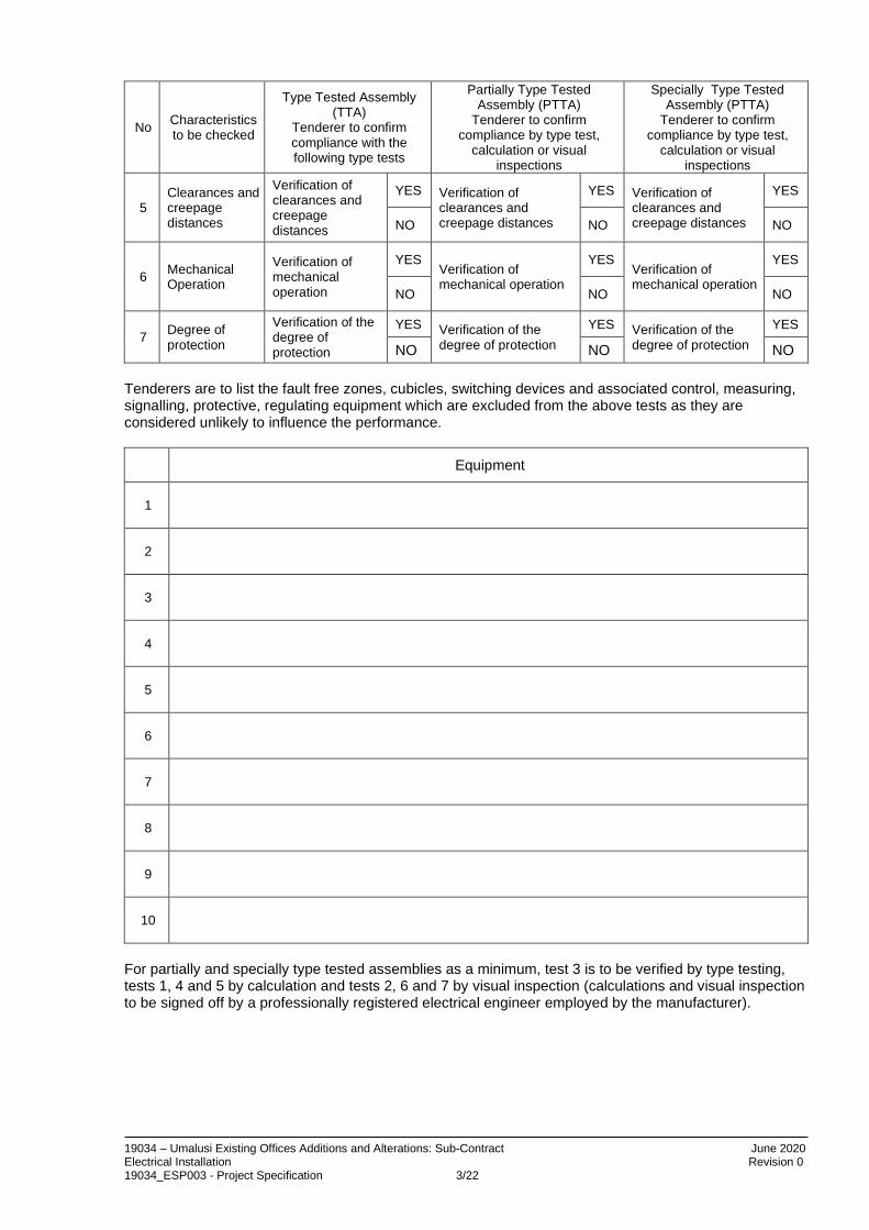
5 Clearances and creepage distances
Verification of clearances and creepage distances
YES Verification of clearances and creepage distances
YES Verification of clearances and creepage distances
YES
NO NO NO
6 Mechanical Operation
Verification of mechanical operation
YES Verification of mechanical operation
YES Verification of mechanical operation
YES
NO NO NO
7 Degree of protection
Verification of the degree of protection
YES Verification of the degree of protection
YES Verification of the degree of protection
YES
NO NO NO Tenderers are to list the fault free zones, cubicles, switching devices and associated control, measuring, signalling, protective, regulating equipment which are excluded from the above tests as they are considered unlikely to influence the performance.
Equipment
1
2
3
4
5
6
7
8
9
10
For partially and specially type tested assemblies as a minimum, test 3 is to be verified by type testing, tests 1, 4 and 5 by calculation and tests 2, 6 and 7 by visual inspection (calculations and visual inspection to be signed off by a professionally registered electrical engineer employed by the manufacturer).

19034 – Umalusi Existing Offices Additions and Alterations: Sub-Contract June 2020 Electrical Installation Revision 0 19034_ESP003 - Project Specification 3/23
22. Cabling and Busbars 22.1 Busbars
Busbars are to consist of copper conductors. Phase conductors are to be fully rated for the current rating as shown with a maximum rise of 15°C (on the copper) above an ambient room temperature of 40°C. The neutral bar is to be at least 50% of the rating of one of the phase conductors and made of copper. No internal earth conductor is required. Conductors to be manufactured form 99% pure electrolytic copper. The spacing of the bars is not to exceed 10 mm between the phase conductors and phase to neutral, except at the termination and joints. (Supplier to advise spacing at the joints at time of tender.) The busbar is to be rated at IP54 over the complete length of busbar including joints. Joint covers are to be manufactured with a fixing arrangement to allow easy and safe installation and removal, (cable ties are not acceptable). Joint cover material shall allow infra red testing of the joints without removing the cover. Transformer and Main LV board panel flanged end feed units are to be suitably arranged to terminate on to transformer bushings via flexibles. Flexibles to be supplied with the busbar flanged end unit. The busbar (including covers) shall be painted hammertoe grey Plascon CEP 5010. Each section of busbar is to be tested at 2 kV for 1 minute at the factory and on site prior to installation on site. On completion of the busbar installation the busbar is to be retested at 2 kV for 1 minute. All the above tests are to be recorded on a single test sheet per busbar run and submitted to the Engineer prior to energising. Copies of the above test to be included in the as built manuals.
22.2 Cabling
a) PILCSTA and PILCSWA Cables
Paper-insulated cables shall be manufactured in accordance with SANS 97. Cable-end boxes shall comply with BS 542 and the filling compound to BS 1858. The ends shall be terminated in cable-end boxes filled with bituminous cold filling or resin oil semi-fluid compound or heat-shrinkable terminations in accordance with the specification, and to the manufacturer's recommendation. Before terminating or joining PILCSTA and PILCSWA cables, a test to establish the presence of moisture must be carried out. The test procedure must be forwarded to the Engineer for approval. The armouring shall be bonded to the main earth bar of the switchgear or transformer, but the bond shall be easily removable for testing purposes. All cut cable-ends, which will be exposed to the atmosphere for more than two hours shall be sealed and wiped to prevent penetration of moisture.
b) PVC-Insulated Cables
PVC-insulated cables shall be manufactured in accordance with SANS 150.

19034 – Umalusi Existing Offices Additions and Alterations: Sub-Contract June 2020 Electrical Installation Revision 0 19034_ESP003 - Project Specification 3/24
PVC cable glands shall be made of a barrel carrying a cone bush screwed into one end and a nickel-plated brass nipple and galvanised steel lock-nut on the other end. Flameproof glands shall comply with SANS 808 Groups 1, 2 (a) and 2 (b). All cable ends shall be terminated with approved glands ensuring a watertight connection between the sheath, gland and equipment. In cases where copper ECC earth conductors are jointed to the armouring, special glands adhering to SANS 150-1970 par. 5.8.3 (c) shall be used for ECC cables. The glands to be used shall be constructed so that the armouring of the cable is clamped between two bevelled cores with a screw-clamp, with the cable gland screwed to the gland plate or equipment and fixed with a locknut. A neoprene or PVC shroud of the correct size shall be used to seal the gland and sheath watertight. Cable end shall be supplied with the necessary earth connection. A supporting channel or other approved means of support shall be provided to remove mechanical stress from the cable glands.
c) XLPE Cables
XLPE isolated cables shall be manufactured in accordance with SANS 1339 Table A. Cable ends shall be terminated strictly in accordance with manufacturer's specifications. The termination shall withstand the same test voltage as the rest of the cable. Termination for XLPE cables must have a satisfactory stress relief in order to keep the partial discharges extinguished. Outdoor termination must be able to withstand air pollution and bad weather without any signs of surface current tracking. Taped or prefabrication terminations may be used, in accordance with the manufacturer's recommendation.
d) Cable Installation
The storage, transportation, handling and laying of cables shall be according to first-class practice, and the Contractor shall have adequate and suitable equipment and labour to ensure that no damage is done to the cables during such operations. All possible care shall be exercised in off-loading cables on site. Any drums which show signs of damage or mishandling, shall not be used and must be replaced with fresh stocks. Cable drums remain the property of the Contractor and shall be removed from site and disposed of by him. The Contractor is wholly responsible for making his own arrangements regarding the transportation to and from site, and the storage on site, of material and equipment; and the loss of or damage thereto, during transportation or storage on site, of material and equipment. Tenderers shall satisfy the Engineer that they are competent to install/lay the cables specified, and must have had previous experience of cable laying and jointing of the sizes and types of cable indicated.

19034 – Umalusi Existing Offices Additions and Alterations: Sub-Contract June 2020 Electrical Installation Revision 0 19034_ESP003 - Project Specification 3/25
Where cables have to be drawn around corners, skid plates shall be used for this purpose, and these plates shall be well lubricated. The skid plates shall be securely fixed between rollers and shall be constantly examined during cable-laying operations. Cables shall be visually inspected for damage during and after laying. Any damage shall be reported immediately to the Engineer, who will advise as to what action is to be taken. The intention to carry out all cable-laying operations must be given to the Engineer, in advance, to allow inspection of the works. Cable pulling and laying shall preferably be done manually wherever possible. Mechanical means, such as winches and the like, may only be used subject to the approval of the Engineer. No cable shall be subjected to a tension exceeding that stipulated by the cable manufacturer. The Contractor shall maintain an approved means of communication between operators at the pulling end and the drum end of the cables, during laying operations. L.V. cables (except where more than one run in a pipe) shall be spaced at least 150 mm apart. Two pilot cables can be run next to each other but must be 600 mm from the nearest 11 kV cable. Cables may not be buried or laid on top of each other. Cable pipes must maintain or exceed the specified cable spacings. Where additional pipes or cable protection materials are required to be laid, the Engineer shall be advised timeously of the location and quantity of such materials required. The Contractor shall be responsible for the laying and jointing of these pipes, at a rate agreed before work commences. All cables are to be labelled at each end and at every change in direction or position within a group of cables. Cables are to be labeled at both sides of horizontal or vertical penetrations through structure or building fabric. Whenever cables enter building, or are exposed for any reason, the exposed portion shall be suitably protected by means of concrete slabs or suitable pipes or ducts, which shall be galvanised if of steel construction.
e) Testing of Cables
Low tension cables shall be tested to earth and between phases, with a 500 Volt “Megger” test set.

19034 – Umalusi Existing Offices Additions and Alterations: Sub-Contract June 2020 Electrical Installation Revision 0 19034_ESP003 - Project Specification 3/26
11 kV cabling shall be as follows :
500 V Megger between phases
500 V Megger between phases and SWA/copper
tape
Pressure Test sheath to 4 kV DC between armouring and mass of earth
for 1 minute
Pressure Test Phase to
phase at 12 kV DC for 10
minutes
Cable drum arrival on site X X - -
After cable installed and before ends prepared
X X X -
After ends are prepared, before bolting to equipment
X X - X
On completion of the test on any cable, the Contractor shall, without delay, submit 3 (three) copies of Certified Test Reports to the Engineer. The costs of all the tests mentioned above shall be borne by the Contractor as part of the tendered price. The Engineer reserves the right to carry out any further tests deemed necessary, using the Contractor's instruments and equipment.

19034 – Umalusi Existing Offices Additions and Alterations: Sub-Contract June 2020 Electrical Installation Revision 0 19034_ESP003 - Project Specification 3/27
23. Cable Trays and Ladders 23.1 General
Cable trays and ladders shall comply with SANS 763 with respect to finishes. The Contractor shall supply and install all cable trays and/or ladders as specified or as required including the necessary supports, clamps, hangers, fixing materials, bends, angles, junctions, reducers, T-pieces, etc. He shall further liaise with the Main Contractor for the provision of holes and access through the structure and finishes.
23.2 Supports
Trays shall be supported at the following maximum intervals: 1.6mm Thick metal trayswith 12mm return 1000mm Metal trays with folded overreturn and 50mm upstand 1220mm 2.4mm Thick metal trays and 75mm return 1500mm Metal cable ladders other than those mentioned below 1500mm 3.0mm Thick PVC trays with 40mm return 1000mm 4.0mm Thick PVC trays with 60mm return 1500mm
In addition, trays and ladders shall be supported at each bend, offset and T-junction. The above spacing of supports is applicable to both vertical and horizontal installation of trays and ladders.
23.3 Joints
Joints shall be smooth without projections or rough edges that may damage the cables. The Contractor will be required to cover joints with rubber cement or other non-hardening rubberised or plastic compound if in the opinion of the Engineer joints may damage cables. Joints shall as far as possible be arranged to occur at supports. Where joints do not coincide with supports, joint shall, in the case of trays with single returns, be made by means of wrap-around pieces of the same thickness of the tray and at least 450mm long. The two cable tray ends shall butt tightly at the centre of the splice and the splice shall be bolted to each cable tray by means of at least eight round head bolts, nuts and washers. Splices shall have the same finish as the rest of the tray. Where joints which do not coincide with supports occur in trays with folded over returns, tight fitting metal guide pieces, at least 450mm long, shall be inserted in the folded return to provide the necessary support to the two cable tray ends. Splices as described above shall be provided at joints, which do coincide with supports if the loaded tray sags adjacent to the joint due to the interruption of the bending moment in the tray.
23.4 Fixing
Trays and cable ladders shall be bolted to supports by at least two round head bolts per support. Bolts shall be securely tightened against the tray surface to avoid projections, which might damage cables during installation.
23.5 Fixing to the Structure
The support for cable trays and ladders shall in all cases be securely fixed to the structure by means of heavy duty, expansion-type anchor bolts. Cantilevered trays shall be supported at two points with a minimum of two expansion bolts per support. It is the responsibility of the Contractor to ensure that adequate fixing is provided since cable trays and ladders that work loose shall be rectified at his expense. The fixing shall take into account site conditions that prevail during installation.

19034 – Umalusi Existing Offices Additions and Alterations: Sub-Contract June 2020 Electrical Installation Revision 0 19034_ESP003 - Project Specification 3/28
23.6 Earthing
Metal trays and ladders shall be bonded to the earth bar of the switchboard to which the cables are connected with a Cu PVC cable. Bare copper stranded conductors or copper tape shall be bolted to the tray or ladder to ensure electrical continuity. These shall be installed on the outside of the tray to ensure they are visible and are not damaged by cable installation.
23.7 Expansion Joints
Where cable trays/ladders have to cross expansion joints, the trays/ladders must form a gap of at least 25mm between the two sections. Cables installed across expansion joints, must have enough slack to accommodate the expansion of the building.

19034 – Umalusi Existing Offices Additions and Alterations: Sub-Contract June 2020 Electrical Installation Revision 0 19034_ESP003 - Project Specification 3/29
24. Conduit and Wiring Channels
Unless otherwise specified, all conduit is to be concealed by casting/building into walls and slabs, or by running in ceiling spaces and within purlins. Conduit runs to wall luminaire outlets shall, in all instances, be from above the outlet and not below via floor slabs. No conduit is permitted in ground slabs, unless otherwise indicated on the drawings, or required by building construction techniques and sequences. Luminaire conduit shall be looped from outlet to outlet, and no additional drawbox positions will be permitted. No more than two right-angled bends between draw boxes is permitted. All 150 x 50, 150 x 150, or larger, terminal conduit boxes shall be of galvanised steel type. The corresponding PVC type will not be accepted. PVC round conduit boxes that have covers fixed by screwing directly into the PVC box, are unacceptable. In coastal areas (within 70 kms of the coastline) all galvanised sheet steel outlet boxes are to be given two coats of Red Lead or Glyptal Primer, before installation. Conduit shall only be run parallel or at right angles to outside walls when run in ceiling spaces, unless otherwise indicated on drawings. Exposed metal conduit threads are to be protected against corrosion. No running joints are allowed unless agreed by the Engineer, in writing. Black enamelled steel conduit may not be used in coastal areas. All steel conduit systems must be electrically continuous. PVC conduit systems are to be provided with an earth wire for each circuit. All draw trays shall be sheet steel galvanised and painted as above, or as specified. Conduits across expansion joints shall be arranged in such a manner that each side of the joint is free to move relative to the other, without damage to conduit or wiring. Unless otherwise indicated, only one circuit is to be installed in each conduit. This does not apply to conduits rising from distribution draw trays. In this case the Contractor is to de-rate conductors by 50% (fifty per centum) and ensure that conduit trunking capacity is adequate to provide 50% (fifty per centum) (maximum) occupancy. Final positions of all outlets are to be verified on site with the Structural Engineer's detailed drawings. In general, the following heights above finished floor level, to underside of box are to be observed unless otherwise indicated on the drawings:
Wall switches Door handle height Wall outlets for luminaries 2100 mm Wall mounted socket outlets 500 mm Wall mounted socket outlets in kitchen and over work tops 150mm above counter Bells, buzzers and fire alarm bells 2400 mm Fire alarms Door handle height Telephone outlets 500 mm Clock outlets 2400 mm
Where the Engineer has any reason to suspect that wiring has been damaged during drawing into conduit, the Contractor will be requested to withdraw the wiring for inspection. For pricing purposes sub-contractors should allow for the withdrawing and reinstatement of five circuits, overall.

19034 – Umalusi Existing Offices Additions and Alterations: Sub-Contract June 2020 Electrical Installation Revision 0 19034_ESP003 - Project Specification 3/30
The Contractor should, therefore make due allowance for this. The conduit routes shown on the drawings are schematic, and the Contractor must ensure that the manner of installation and routing of all conduit is carried out in accordance with the Regulations and good engineering practice, and takes cognisance of the relevant architectural/building restraints. The capacity of conduits will be checked on site. Where the recommended capacity is exceeded, the Contractor will be required to re-wire the circuits concerned. All accessories such as boxes for socket outlets, switches, lights, etc., shall be accurately positioned. It is the responsibility of the Contractor to ensure that all accessories are installed level, square, and at the correct height. It shall be the responsibility of the Contractor to determine the correct final floor, ceiling and roof levels in conjunction with the Principal Contractor. Draw boxes shall be installed as inconspicuously as possible and shall not be installed in positions where they will be inaccessible after completion of the installation. Positions of all draw boxes shall be indicated on the "AS BUILT" drawings.
Galvanised steel draw wires shall be installed in all unwired conduits, e.g., conduits for future extensions, telephone installations and other services. A maximum of two 90° bends or the equivalent displacement will be allowed between outlets and/or boxes. Care shall be taken to prevent debris or moisture entering conduits during and after installation. Conduit ends shall be sealed by means of a solid plug, which shall be screwed to the conduit end. Conduits shall be cleaned and swabbed to remove oil, moisture or other debris that may be present before conductors are installed. Swabs shall not be attached to the conductors.
24.1 Termination of Conduits
a) Switchboards, Power skirting, etc. Conduits shall be terminated by means of a brass female bush and two lock nuts in distribution boards and power skirting, etc. The conduit end shall only project far enough through the hole to accommodate the bush and lock nut.
b) Draw Boxes
A female bush and two lock nuts shall be used to terminate conduits at draw boxes should there be sufficient room in the box. Where there is insufficient room, a coupling and a brass male bush may be used with sufficient allowance for the reduction of the internal diameter by the male bush.
24.2 Screws, Bolts and Nuts
Steel locknuts of thick gauge steel with milled sides shall be used in all cases. Cadmium-plated bolts and nuts shall be used, except where the installation is exposed to the weather, in which case brass bolts and nuts shall be used. Screws shall be installed in all tapped holes in fittings and accessories to prevent damage to the screw thread by concrete or plaster. The screws shall be screwed down completely to prevent damage to the thread on the screw.
24.3 Installation in Concrete
a) Timeous Installation
In order to prevent delay to building operations, the Contractor shall ensure that all conduits and accessories to be cast into concrete are placed in position in good time. Once the installation has been completed, the Contractor shall advise

19034 – Umalusi Existing Offices Additions and Alterations: Sub-Contract June 2020 Electrical Installation Revision 0 19034_ESP003 - Project Specification 3/31
the Engineer in order that he may inspect the installation prior to concrete being cast. The Contractor or his representative shall be in attendance when the concrete is cast.
b) Draw Boxes and Joints Draw boxes, expansion joints and round ceiling boxes shall be installed where required, and shall be neatly finished to match the finished slab and wall surfaces. Ceiling draw boxes shall be of the deep type. In hollow tile slabs, rear entry draw boxes shall be used. In columns where flush mounted draw boxes are installed, the conduits shall be offset from the surface of the column immediately after leaving the draw box. Draw boxes shall be installed at maximum intervals of 15m in straight runs. Where these boxes will be visible on the bottom of ceiling slabs, the boxes shall be positioned so that they will be hidden by light fittings, etc. Couplings are to be taped up with adhesive rubber tape to prevent the ingress of concrete slurry.
c) Cover Plates Draw boxes and/or inspection boxes shall where possible; be grouped together under a common approved plate. The cover plate shall be secured by means of screws.
d) Fixing to the Shuttering All conduits, draw boxes, etc., shall be securely fixed to the shuttering to prevent displacement when concrete is cast. Draw boxes and outlet boxes shall preferably be secured by means of a bolt and nut installed from the back of the box, through the shuttering. Wire will not be accepted for securing boxes to the shuttering where off-shutter finishes are required. Where fibre-glass shuttering is used, the conduits and boxes shall be fixed to the reinforcing steel only and no holes shall be drilled or made in shuttering. All draw boxes and outlet boxes shall be plugged with wet paper before they are secured to the shuttering.
e) Expansion Joints Conduits shall not be installed across expansion joints if avoidable.
f) Screed Where conduits are installed in screed, the top of the conduit shall be at least 20mm below the surface of the screed. A minimum distance of twice the outside diameter of the conduit shall be left free between adjoining conduits. Conduits shall be secured to the concrete slab at intervals not exceeding 2.0m.
g) Inspection After removal of shuttering, all conduits shall be checked to ensure that they are not blocked. Errors that occur during the installation of the conduits, or any lost draw boxes, or blocked conduits shall be immediately reported to the Engineer in order that an alternative route may be planned and approved before any additional concrete is cast.

19034 – Umalusi Existing Offices Additions and Alterations: Sub-Contract June 2020 Electrical Installation Revision 0 19034_ESP003 - Project Specification 3/32
24.4 Surface Installation
a) Appearance All conduits shall be installed horizontally or vertically as determined by the route. Where conduits are to be installed directly alongside doorframes, beams, etc., that are not true, the conduits shall be installed parallel to these.
b) Saddles
Conduits shall be firmly secured by means of equidistant spaced saddles. Conduits shall be secured within 150mm before and after each 90 bend. Saddles shall be fixed by means of screws and plugs and not by means of nails.
c) Joints
Joints will only be allowed in surface conduit lengths exceeding 3500mm. d) Accessories
Inspection bends or tee pieces shall not be used. Non-inspection type bends may be used in the case of 32mm or 50mm diameter conduits. All draw boxes supporting light fittings or other equipment shall be fixed independently of the conduit installation.
e) Offsets
Where an offset is required at conduit terminations or cross-overs, the conduit shall be saddled at the offset.
f) Cross-overs
Conduit routes shall be carefully planned to avoid cross-overs. Where a cross-over is unavoidable, one conduit only shall be offset to cross the other. Alternatively, cross-overs shall be installed in purpose-made boxes.
g) Parallel Conduit Runs
Parallel conduit runs shall be equidistantly spaced and saddles shall be installed in line. Alternatively, a special clamp can be used to secure all conduits together.
h) Painting of Conduits
All surface mounted conduits and accessories shall be painted with high quality enamel paint or as otherwise specified. The colour shall comply with the colour code specified for the installation, or where no code has been specified, shall match the colour of the surrounding finishes.
24.5 Future Extensions
a) Open Roof Spaces
Conduits for future switch and socket outlets in roof spaces with more than 900mm free space shall terminate 40mm above the tie beams. The conduit ends shall be threaded and provided with a coupling and brass plug.
b) Concrete Slabs
Conduit ends shall protrude 150mm from the concrete to facilitate the installation of future extensions. All such conduits shall be connected to a draw box, which is cast into the concrete within 2m of the end of the concrete. Conduit ends shall be threaded and provided with a coupling and brass plug. In cases where holes

19034 – Umalusi Existing Offices Additions and Alterations: Sub-Contract June 2020 Electrical Installation Revision 0 19034_ESP003 - Project Specification 3/33
cannot be drilled through the shuttering to accommodate the conduit end, a deep draw box with rear entry may be placed around the conduit end.
c) Cover Plates
All boxes for future switch and socket outlets shall be covered by blank cover plates. All boxes for future light fittings shall be covered with round oversized cover plates.
24.6 Expansion Joints
Where conduits cross expansion joints in the structure, approved type draw boxes, which provide a flexible connection in the conduit installation, shall be provided. The draw box shall be installed adjacent to the expansion joint of the structure and a conduit sleeve one size larger than that specified for the circuit, shall be provided on the side of the draw box nearest the joint. The one end of the sleeve shall terminate at the edge of the joint and the other shall be secured to the draw box, by means of locknuts and a standard bushed adaptor. The circuit conduit passing through the sleeve shall be terminated 40mm inside the draw box and in the case of metallic conduit; the conduit end shall be fitted with a brass bush. The gap between the sleeve and the conduit at the joint shall be sealed to prevent ingress of wet cement. In the case of metallic conduit, an earth clip shall be fitted to the conduit projection inside the draw box and the conduit bonded to the box by means of 2.5mm² bare copper earth wire and a brass bolt and nut. In addition to an earth wire, which may be specified for the circuit, a 2.5mm² bare copper wire shall be provided between the first conduit box on either side of the joint in the case of metallic conduit. The conduit boxes shall be drilled and tapped, and the earth wire shall be bonded to the boxes by means of lugs and brass screws. Draw boxes and the expansion joint shall be provided with a suitable steel cover plate fixed to the box by means of screws. The cover plates shall be installed before the ceilings are painted. Where a number of conduits are installed in parallel they shall cross the expansion joints of the structure via a single draw box. A number of draw boxes adjacent to each other will not be allowed.
24.7 Chases and Builder’s Work
Electrical materials required to be built-in shall be supplied and fixed in position by the Contractor as required by the programme of the Principal Contractor. The Contractor shall ensure that these materials are installed in the correct positions. On contracts on which there is no builder, the Electrical Contractor shall cover conduits installed in chases by means of a 4:1 mixture of coarse sand and cement, finished 6mm below the face of the plaster and roughened. In all cases, chases shall be deep enough to ensure that the conduits are at least 20mm below the finished plaster surface. Where the Contractor is responsible for the cutting of chases, building-in of conduits or other equipment, he will be held responsible for all damage as a result of this work and will be required to make good. Chases shall be carried out by means of a cutting machine. Under no circumstances shall face brick walls or finished surfaces be chased or cut without the written permission of the Engineer. Where it is necessary to cut or drill holes in the concrete structure, the prior permission of the Structural Engineer shall be obtained.
24.8 Wiring Channels

19034 – Umalusi Existing Offices Additions and Alterations: Sub-Contract June 2020 Electrical Installation Revision 0 19034_ESP003 - Project Specification 3/34
The channels shall be either hot dip galvanised or electro-galvanised, shall be coated with cold galvanising at all joints, sections that have been cut and at places where the galvanising has been damaged. Powder coated ducts shall be touched up at joints, cuts and damaged portions, using paint recommended by the manufacturer of the channels.
a) Cover Plates
Channels up to 125mm wide shall have snap-in cover plates of metal or PVC, whilst channels wider than 125mm shall have metal cover plates fixed in position by screws. The finish of steel cover plates shall be the same as that of the channels.
b) Accessories All accessories, i.e., hangers, brackets, etc., shall be purpose-made and in general have the same finish as the channels.
c) Capacities of Channels
Trunking is defined as a channel having one or more sides removable for access to wiring, whilst ducting has no removable sides. In the case of trunking, the overall cross-sectional areas of all the conductors, including insulation, shall not exceed 45% of the internal cross-sectional area of the trunking whilst in the case of ducting, this figure shall be 40%. Where trunking or ducting is run in a distribution board, it shall be filled to not more than 30% unless it is ventilated, in which case, the former figures shall apply. Common wire ways will be permitted only in the case of conductors carrying relatively low currents, namely lighting and single phase socket outlet circuits. In such cases, the maximum number of wires per conduit shall be in accordance with SANS 10142.
d) Fixing of Channels
The Contractor shall supply and install all hangers, supports or fixings for the channels. Channels up to 75 x 75mm shall be supported at maximum intervals of 600mm and larger channels at maximum intervals of 1m. Channel runs shall be carefully planned to avoid clashes with other services and to ensure that all covers can be removed after completion of the entire installation. Purpose-made clamps, hangers etc., shall be used as required. Where it is not possible to support the channels at the specified intervals, they shall be supported in a sound manner to the satisfaction of the Engineer.
e) Installation in Concrete
Channels shall be filled with polystyrene or other suitable fillers to prevent ingress of cement and shall be securely fixed in position to the shuttering.
f) Joints
Adjoining lengths shall be aligned and securely jointed by means of fishplates fixed by mushroom bolts, washers and nuts or connection pieces that are pop-riveted to both adjoining sections. Adjoining sections shall butt tightly. Covers shall fit tightly across the joint. Where channels cross expansion joints in the concrete, suitable expansion joints shall be provided in the channels by means of fishplates pop-riveted or screwed to the channel on one side of the expansion joint and floating freely in the channel on the other side of the expansion joint.

19034 – Umalusi Existing Offices Additions and Alterations: Sub-Contract June 2020 Electrical Installation Revision 0 19034_ESP003 - Project Specification 3/35
g) Support for Conductors
All conductors in inverted cable channels shall be retained by means of metal clips or metal spacer bars at not less than 1m centres. Clamps shall be provided on suitable draw boxes for this purpose.
h) Internal Finishes
Burrs and sharp edges shall be removed and the inside edges of all joints shall be lined with rubber cement or other suitable rubberised or plastic compound to prevent laceration of the conductor insulation. All holes through which conductors pass shall be fitted with grommets.
i) Vermin Proofing
All wire ways shall be vermin proof after installation. Holes shall be covered by means of screwed metal plugs or by means of metal strips that are bolted or pop-riveted to the channel.

19034 – Umalusi Existing Offices Additions and Alterations: Sub-Contract June 2020 Electrical Installation Revision 0 19034_ESP003 - Project Specification 3/36
25. Wiring Installation
25.1 Type of Conductors
All wiring shall be carried out with PVC insulated, stranded copper conductors and bare stranded copper earth wires, complying with SANS 10150. Conductors shall be installed in conduit, trunking or ducting. Under no circumstances will open wiring be acceptable. Where surface wiring cannot be avoided, aluminium sheathed cable may be used instead of surface mounted conduit, but prior permission from the Engineer shall be obtained. Conductors connected to different distribution boards shall not be installed in a common wire way.
25.2 Looping
All wiring shall be carried out by means of the loop-in system. Jointing of conductors shall only be carried out in accessible boxes or in conduit runs. Conductor jointing shall be carried out by means of ferrules insulated with PVC tape.
25.3 Grouping of Circuits
Where conductors of more than one circuit are installed in wire ways, the conductors of each circuit shall be taped together at intervals of one metre with PVC tape. A common unbroken earth conductor may be installed into the wire ways, and subsidiary earth wires to the various outlets, shall be connected to this earth wire by means of crimped connections.
25.4 Different Phases
With the exception of 3-phase outlets, circuits of different phases shall not be present at switch or socket outlet boxes.
25.5 Vertical Wireways
Conductors installed in vertical wireways shall be secured at intervals not exceeding 5m in order to support the mass of the conductors. Suitable clamps shall be provided for this purpose.
25.6 Connections
When more than one conductor enters a terminal, the strands shall be securely twisted together. Under no circumstances shall strands be cut off.
25.7 Earthing Conductors
When earth continuity conductors are looped between outlets, the looped conductor ends shall be twisted together and then soldered or ferruled in order to ensure that earth continuity is maintained when the conductor is removed from a terminal.
When a single earth conductor is used for a group of current carrying conductors as in power skirting trunking or ducting, the size of the earth conductor shall be to the approval of the Local Supply Authority.
25.8 Single Pole Switches
Single pole switches shall be connected so as to break the phase conductor, and not the neutral conductor.
25.9 Wiring in Partitions

19034 – Umalusi Existing Offices Additions and Alterations: Sub-Contract June 2020 Electrical Installation Revision 0 19034_ESP003 - Project Specification 3/37
Where wiring is installed in demountable partitions, the metal supports for the partitions may be utilised for carrying wiring subject to:
a) The conductors not being exposed,
b) the metal supports being properly earthed,
c) a separate bare earth continuity conductor being drawn in together with the
current carrying conductors, with this earth continuity conductor being connected to the metal parts of the switches and socket outlets, and
d) the conductors being installed in non-flammable sections of the partitions.
Conductors enclosed in copper braiding may be installed in demountable partitions.
The braiding may be used as the earth continuity conductor. This wiring shall be jointed to the conduit or cable installation by means of jointing the conductors and earth continuity conductor in a suitable draw box with ferrules or screwed terminal blocks. This draw box shall be situated immediately above the partition.
25.10 Colours
The colours of conductor insulation for sub-circuits shall, as far as possible, correspond with the colour of the supply phase. The colours of conductors for the wiring of two-way and intermediate switches shall differ from those of phase conductors.
Not more than two wires are to be terminated at any one terminal.
Before terminating, the strands of the conductor are to be tightly twisted to ensure a good and lasting terminal contact. Untwisted wire terminations will be rejected.
Insulation of wiring or cable conductors that have been nicked or cut during preparation of the end will be rejected if these cannot be adequately reinstated by oversleeving.
Insulation must not be pared back excessively at the terminal. Maximum excess of 3 mm is permitted.
Wiring connections to luminaires should either be looped in and out without being cut in half or a scotch clip type T off connection used to avoid intermittent and difficult to locate open circuits occurring.
25.11 Within Distribution Boards
All boards are to be left in a completely clean and dust free condition. Incoming wiring must be neatly run and located clear of equipment. During installation, paintwork is to be protected at all times.
Unless otherwise agreed, not more than one live or incoming supply is permitted per board and all incoming live wiring is to be simultaneously isolated by a single action isolating device.
Live terminals in boards are to be shrouded.
All terminals and busbars are to be checked for tightness.
Circuit cards are to indicate circuit numbers as on the layout drawings, phasing, type of circuit and circuit identity i.e. "s.s.o's for fridges 11 to 15" etc.
Final circuit labelling is to be given to the board manufacturer by the contractor and shall reflect layout drawing circuit number and phasing.

19034 – Umalusi Existing Offices Additions and Alterations: Sub-Contract June 2020 Electrical Installation Revision 0 19034_ESP003 - Project Specification 3/38
All metal in or on boards is to be effectively earthed.
Any holes required on gland plates or boards are to be neatly punched and the bare metal treated to prevent rust.
25.12 Wiring Terminals
a) Terminal bodies and screws shall be of non-corrosive metal, enclosed in fire
resistant, moulded plastic insulating bodies. Terminal bodies or screws shall not project beyond the insulating material and shall afford suitable protection against accidental contact by personnel and against short circuits and tracking.
b) The construction of the terminal block and mounting rail shall be such as to
ensure a firm and positive location of the terminal blocks. It shall be possible to add additional terminal blocks within the terminal sequence without having to disconnect or dismantle the terminal strip. The terminal blocks shall be held in position by means of standard end clamps.
c) It shall be possible to intermix terminals of various sizes, i.e. for different sizes of
conductors, whilst utilising the same mounting rail. Where smaller terminal blocks occur adjacent to larger terminal blocks, suitable shielding barriers shall be inserted to cover the terminals that might otherwise be exposed.
d) The terminal bodies and clamping screws shall be so constructed as to ensure
that conductors are not nicked or severed when the clamping screws are tightened. Screws shall not come in direct contact with the conductors.
e) Terminals shall be sized and rated to match the conductors that are connected to
them. f) Each terminal block shall have provision for clip-in numbering or labelling strips to
be installed, together with protective, clear caps over the sheets.

19034 – Umalusi Existing Offices Additions and Alterations: Sub-Contract June 2020 Electrical Installation Revision 0 19034_ESP003 - Project Specification 3/39
26. Luminaires 26.1 General
The mounting positions of light fittings shall be verified on site. All fittings shall be placed symmetrically with respect to ceiling panels, battens, beams, columns or other architectural features of the space unless otherwise shown. The layout as shown in the document shall generally be adhered to, but any discrepancies or clashes with structural or other features must be referred to the Engineer before commencing with the installation. Should the Contractor neglect to refer such discrepancies to the Engineer, costs incurred as a result of subsequent alterations to suit the building or structural features will be for the Contractor's account.
26.2 Cover Plates
Cover plates shall be fitted over all draw boxes and outlets intended for fittings that are not covered by the fitting canopy, lamp holder, ceiling rose or similar accessories.
26.3 Fixing to Draw Boxes
Where an outlet box or draw box provides the necessary support for light fittings, all fittings with the exception of fluorescent fittings mounted against the ceiling shall be fixed directly to the box. Fittings with a mass in excess of 10kg shall however be suspended independently of the outlet box.
26.4 Hangers and Supports
Where provision has not been made for the fixing of fittings, the Contractor shall supply the necessary supports, hangers, conduit extensions, angle brackets or any other fixing method approved by the Engineer.
26.5 Suspended Luminaires
The necessary hangers shall be provided where fittings, which are of the non-suspension type, have to be fixed below roof slabs. The use of 20mm conduits fixed to the roof slab is preferred. Provision shall be made for adjustments to enable the levelling of fittings. Suspended conduit shall be fixed to the ceiling by means of screwed dome lids, bolts and nuts. Ball-and-joint type dome lids shall be used where conduit lengths exceed 600mm. Wiring shall be installed in the conduit hangers.
26.6 Suspended Wiring Channels
Light fittings (especially fluorescent fittings) may also be suspended from ceilings by means of suspended metal channels. The metal channel may be supported by conduits or threaded rods. Should metal rods be utilised, these shall be screwed to anchor bolts fixed in the roof slab. Wiring shall either be installed in conduits fixed to the metal channel or in the metal channels, covered with a suitable cover plate. Purpose-made clamps shall be used to fix the fittings to the wiring channel.
26.7 Fittings Fixed to False Ceilings
In all cases where light fittings are fixed to false ceilings, the Contractor shall ensure that the ceiling is capable of carrying the weight of the fittings before commencing installation. Should any doubt exist in this regard, the matter shall be referred to the Engineer. When fluorescent fittings are fitted to false ceilings they should be flush mounted with no visible gap if possible. Where the construction of the fitting causes a gap between the fitting and ceiling, the maximum gap allowable is 2mm. The fitting shall be fixed to the ceiling beams. In the case of tiled ceilings with exposed or concealed T-section supports, the fittings shall be fixed to the metal supports by means of butterfly screws or bolts with

19034 – Umalusi Existing Offices Additions and Alterations: Sub-Contract June 2020 Electrical Installation Revision 0 19034_ESP003 - Project Specification 3/40
nuts and washers. Self-tapping screws may not be used. Fittings shall be neatly fixed with regard to the ceiling layout.
26.8 Glassbowl Fittings
Unless specified to the contrary, glass bowl fittings shall be installed with the underside at least 2m above finished floor.
26.9 Fluorescent Fittings Fixed to Concrete Slabs
Fluorescent fittings to be installed directly against concrete slabs or walls shall be fixed to the outlet box and at two additional points. Shot-fired fixings are not acceptable. If specified or where approved by the Engineer, fluorescent fittings may be fixed to metal channels installed against concrete slabs or walls. The metal channel fixing may, in this case, be shot-fired. Purpose-made clamps shall be used to fix fittings to wiring channels.
26.10 Continuous Rows of Light Fittings
In cases where fluorescent fittings are installed end to end in a continuous row only one connection outlet per circuit need be supplied. All fittings shall be coupled to one another by means of nipples or brass bushes and locknuts to ensure that wiring is not exposed and that earth continuity is maintained. Fittings on the same circuit may be wired through the channel formed by the fitting bodies. In this case internal connections shall be made at terminal blocks. The wiring for any other circuits or outlets, even though these may be in the same row may not be installed through the fitting canopies. The Contractor shall ensure continuous rows are straight and parallel to the relevant building lines.
26.11 Recessed Light Fittings In all false ceilings where wiring channels are used, recessed light fittings shall be connected to the main wiring channels by means of 5A sockets mounted on or adjacent to the channels and 0.5mm², 3 core flexible cable complete with 5A plug tops, not exceeding 3m in length.
26.12 Special Ceilings
In cases where special ceilings e.g., aluminium strips, decorative glass, metal leaves, etc., are to be installed, the Contractor and Manufacturer of the ceiling shall agree upon the method of fixing of light fittings in the ceiling.
26.13 Bulkhead Fittings
Surface mounted bulkhead fittings shall not be screwed directly to conduit ends. The conduit shall terminate in a round draw box at the top or rear of the fittings. The PVC insulated conductors shall terminate in a porcelain terminal strip in the draw box. Asbestos or silicon-rubber insulated conductors shall be installed from the terminal strip to the fitting lamp holder. Screw-type connectors are not acceptable (e.g., "SCREW IT").
26.14 Connections to Light Fittings
a) Connectors
Where connectors have to be provided to effect connections to the wiring of light fittings and other appliances, brass screw couplers shrouded in porcelain, neoprene or PVC or approved spring steel locking connectors insulated in unbreakable material shall be used. Other types of connectors are not acceptable (e.g., "SCREW IT").
b) Knock-outs
19034 – Umalusi Existing Offices Additions and Alterations: Sub-Contract June 2020 Electrical Installation Revision 0 19034_ESP003 - Project Specification 3/41
Where knockouts are used for the wiring of light fittings and other appliances, brass bushes or gripper glands shall be provided.
c) Type of Conductor
PVC insulated conductors, unless protected by an approved heat resistant sheathing, should not be used where the temperature of the insulation is likely to exceed 70º C. In fittings capable of housing incandescent lamps above 60W, the interconnecting wiring from the lamp holder to the circuit wiring shall consist of varnished cambric insulated roved and braided asbestos or heat resisting silicon compound insulated conductors. Refer also the provisions of SANS 10142, Clause 6.21.1 (f).
26.15 High Bay Fittings
The Contractor and luminaire manufacturer shall decide upon the method of fixing fittings in the ceiling, whether by suspending from the roof purlins or mounting on cross-beams. The Engineer shall approve the method before the fittings are fixed. Fittings must be fixed at least 1m above the maximum working height, e.g., above the maximum reach of cranes. The lighting circuits shall be wired with 4mm² PVC insulated conductors in a 3-phase configuration and 2.5mm² bare copper earth conductors installed in "Unistruts". High-bay fittings shall be suitable to accommodate 250W or 400W elliptical or tubular mercury vapour coated, high-pressure sodium or metal halide lamps and associated control gear as required. All high-bay fittings shall be supplied with a safety chain.
26.16 Tubular Fluorescent Lamp Luminaires for Interior Applications a) General
Light fittings, associated equipment and control gear shall be new and unused and shall be supplied complete with lamps, control gear, diffusers, mounting brackets etc., as applicable, and shall be delivered to site in a protective covering. Tenders shall be accompanied by full descriptive information of the light fittings offered. Photometric data, i.e., polar curves and coefficients of utilization certified by the SABS shall be submitted with tenders for luminaires offered. Photometric data shall not be older than 2 years.
b) Technical Requirements
Tubular fluorescent lamp luminaires shall bear the SABS mark and comply fully with SANS 1119 and all amendments as well as the additional requirements of this specification. Components shall bear the SABS mark where applicable. The reflector shall be firmly held in position with a latching device operating on one of the following principles:
i) Spring steel latches. ii) Spring loaded latches and locating pins.
ii) Non-detachable plated metal or plastic screws, with or without locating pins.
Plastic used as a spring mechanism is not acceptable as a fixing device for reflectors.

19034 – Umalusi Existing Offices Additions and Alterations: Sub-Contract June 2020 Electrical Installation Revision 0 19034_ESP003 - Project Specification 3/42
All components including screws, bolts and nuts utilized in the construction of the luminaire for fixing its components shall be corrosion proof.
Industrial type luminaires shall be fitted with detachable side reflectors, manufactured of cold rolled steel, not less than 0.7mm thickness. The design of the reflectors shall be such to improve the downward light output ratio and decrease the upward light output ratio to a value of less than 2%.
c) Control Gear for Fluorescent Lamp Luminaires
Ballasts shall comply with SANS 890 and 891 and bear the SABS mark. Ballasts shall further be suitable for the fitting to ensure that the thermal limits specified in SANS 890 and 891 are not exceeded.
d) Lamps
If no colour is specified in the Detail Specification, the light colour shall correspond to colour 2 (4300 °K) of SANS 1041.
e) Lamp Holders
Lamp holders shall preferably be of the spring loaded telescopic type, but ratchet types such as "ROTOLOK" or "TWISTLOCK" are acceptable. Where ratchet types are used a 1mm air path shall be allowed between the lamp cap and lamp holder and the lamp holder shall house a rotational inset to accommodate the lamp rotation. All lamp holders provided shall be suitable to accommodate from 0.5mm² solid core wire and allow for 2.0mm lamp tolerance compensation.
f) Paint Finish
Sheet metal components of the luminaire shall be painted in accordance with SANS 1119. Baked enamel, electro statically applied powder coating or similar proven methods may be used. Care shall be taken to ensure that all edges and corners are properly covered. The finish shall be smooth, glossy and free from grit or any other surface imperfections. Prior to painting, all metal parts shall be thoroughly cleaned of rust, mill scale, grease and foreign matter to a continuous metallic finish. Sand or shot blasting or acid pickling and washing shall be employed for this purpose. The paint process shall conform SANS 1274 type 3.

19034 – Umalusi Existing Offices Additions and Alterations: Sub-Contract June 2020 Electrical Installation Revision 0 19034_ESP003 - Project Specification 3/43
27. Terminal Devices 27.1 General This section covers the requirements for switches and sockets for installation under
normal environmental conditions.
a) Switches shall comply with SANS 10163 as amended.
b) Sockets shall comply with SANS 10164 as amended. 27.2 Escutcheon Plates
Where flush mounted switches or sockets are installed in special wall finishes e.g., wood or board panels, acoustic tiles or other cladding, etc., and where the wall finishes have to be cut to accommodate the switch, it may be necessary to fix an escutcheon plate to the wall to cover the cut-outs. The escutcheon plate shall fit closely around the switch boxes and shall be fixed independently of the switch boxes and cover plates. Bevelled cover plates that overlap the switch boxes shall be used. Cover plates shall be fixed to the switch boxes and shall fit firmly against the escutcheon plate.
27.3 Flush Cover Plates
a) Cover plates shall conform to SANS 163 and SANS 1085 and shall bear the SABS mark.
b) Cover plates shall be finished in ivory coloured baked enamel, anodised
aluminium or natural bronze unless otherwise specified. c) Cover plates shall have bevelled edges which overlap the box in order to mask
rough wall finishes. d) Cover plates shall under no circumstances be cut unless specifically authorised
by the Engineer. Appearance
All boxes and cover plates shall be installed parallel to and in line with relevant horizontal and vertical planes unless specified to the contrary. The sides of adjacent switches, sockets, push-buttons, etc., shall be parallel or perpendicular to each other and uniformly spaced.
27.4 Light Switches Wall and Surface Mounted Switches
a) All light switches shall be installed 1400mm above the finished floor level unless specified to the contrary. Mounting heights given shall be measured from the finished floor level to the centre of the switch.
b) All switches shall be suitable for mounting in 100mm x 50mm x 50mm galvanised
steel or stove enamelled boxes. c) Unless otherwise specified, switches shall be of the tumbler operated microgap,
250V, 16A type and of silent operation. d) Where more than one switch is required at any one position, approved
multiple-gang units shall be used and installed in a common switch box. Watertight Switches

19034 – Umalusi Existing Offices Additions and Alterations: Sub-Contract June 2020 Electrical Installation Revision 0 19034_ESP003 - Project Specification 3/44
a) Switches that are exposed to the weather or are installed in damp areas, shall be
of the waterproof type. b) Watertight switches shall be 16A, single pole, unless specified to the contrary,
and suitable for surface mounting. c) The switch mechanism may be on the front or side of the box but the ON/OFF
positions shall be clearly marked. Pull Switches
a) Pull switches shall be rated 10A as required and shall be suitable for ceiling
mounting on a round conduit box. They shall contain heavy brass contacts and a strong quick acting mechanism, and be suitable for operation on 250V, 50Hz systems.
b) Each switch shall be complete with a 1.25m length of nylon cord.
Partition Switches
a) Light switches installed in mullions shall be purpose-made. b) Switches installed in the metal supports do not require switch boxes. c) Switches may not be flush mounted in partition walls without switch boxes.
27.5 Socket Outlets
a) Switched sockets shall be suitable for use with 400/230V, 50Hz systems and switches and sockets shall be rated not more than 16A, 250V or 63A, 400V unless specified to the contrary.
b) Miniature circuit breakers of the correct rating may be used in lieu of a switch with
single phase sockets where specified. Miniature circuit breakers shall be contained under the same cover plate and shall conform to SANS 156.
Flush Socket Outlets
Flush sockets shall consist of a 16A switch and 3-pin plug receptacle with shuttered live and neutral sockets and an earth socket operating the shutters. The unit shall be suitable for mounting in a standard 100 x 100 x 50mm box.
Mounting Heights Mounting heights given shall be measured from the finished floor level to the centre of the socket. Unless otherwise specified socket outlets shall be installed at the following heights above finished floor levels:
Flush mounted, in general 300mm Surface mounted, in general 1400mm Kitchens, laundries, shops 1100mm Factories, workshops, garages 1400mm
Walls

19034 – Umalusi Existing Offices Additions and Alterations: Sub-Contract June 2020 Electrical Installation Revision 0 19034_ESP003 - Project Specification 3/45
Where the lower portions of brick walls consist of face bricks and the upper portion of the wall is plastered, the outlets shall be installed in the plastered portion of the wall. If however the plastered portion of the wall commences 650mm or more above floor level, the outlets shall be installed in the face bricks. Where a wall has different surface finishes, the outlets shall be installed on one of the walls finishes only and not in the joints between the different wall finishes. All outlets shall be installed at least 150mm away from door frames. Surface Mounted Socket Outlets Sockets for surface mounting shall consist of units equal to the flush mounted units, but contained in a purpose-made pressed steel box, conforming to SANS 1065 and SANS 1085 where applicable. 3-Phase Welding Plugs a) The 3-phase outlets shall consist of 63A switched socket outlets and shall be of
the 4-pin "Crabtree/ Clipsal" type or equivalent, complete with base and matching insert.
b) The construction shall be such that the plug can only be inserted the correct way. c) The plug-in opening shall have a spring-loaded cover to prevent accidental
contact with live parts. Clean Power and UPS Socket Outlets Socket outlets utilised for clean power and UPS circuits with clean earth connections shall be of the Crabtree, Clipsal or approved equal type, with the following features:
a) Distinctively coloured plug top covers, to distinguish the UPS and clean power
male plugs from domestic plugs.
b) A graded series of shaved earth pins to facilitate the necessary discipline for plugging male plugs into corresponding female sockets.
c) The socket chassis assembly shall be designed to avoid any contact between the
fixings to boxes, power skirting, trunking, etc., and the clean earth incoming conductor or clean earth pin.

19034 – Umalusi Existing Offices Additions and Alterations: Sub-Contract June 2020 Electrical Installation Revision 0 19034_ESP003 - Project Specification 3/46
28. Connections to Equipment
28.1 General
This section covers connections to equipment in general electrical installations under normal environmental conditions, up to system voltages of 600V.
28.2 Connections to Distribution Boards Conduit Entries
Wherever necessary, conduits connected to distribution boards shall terminate in a common fabricated sheet-steel draw box, or wiring channel installed in the vicinity of the distribution board. In open roof spaces and/or electrical ducts, this draw box shall be placed in a roof space of not less than 900mm clearance. Lighting and plug circuits may be separately grouped in common conduits or metal ducts (trunking) from the distribution board to the draw box. The draw box shall be of sheet steel with a minimum thickness of 1.6mm and shall be provided with a removable cover plate.
Flush Mounted Distribution Boards
Where flush mounted distribution boards are required, the recessed distribution board tray shall be built into the brick or concrete wall. All conduits from the floor or roof shall be fully recessed and shall be bonded directly to the tray.
Cable Connections
Where underground cables have to be connected to distribution boards, it shall be the responsibility of the Contractor to ensure that sleeves are built in correctly to enable installation and connection of the cable to the switchboard. A metal cable duct with cover plate shall be installed from the sleeve to the switchboard and shall be painted the same colour as the switchboard. The sleeves shall be sealed with non-hardening compound after installation of cables to render the system vermin proof.
Cable Trenches
Where cables in floor trenches have to be connected to wall mounted distribution boards, approved sleeves or conduits shall be installed from the side of the trench to the bottom of the distribution boards.
These sleeves shall be positioned and fixed before the concrete is cast.
28.3 Connections to Motor Driven Equipment An isolator, or starter containing an isolator, shall be installed within 2.0m of the
equipment. The 0.3 requirements of SANS 0142 shall be met. If this isolator cannot be installed on a wall, board or other suitable place an approved free-standing pillar shall be provided. The pillar shall be 1.0m high and outside of normal walkways, etc.
The connection to the equipment shall be made as follows:
a) Metal reinforced plastic or PVC covered metal flexible conduits shall be used with individual conductors or a multicore PVC insulated cable and separate bare earth conductor installed inside the conduit. The flexible conduit shall not be longer than 600mm. Screwed conduit shall be used from the end of the flexible conduit to the isolator and/or starter.
b) Multicore armoured PVC insulated cable and separate bare earth conductor. The
installation and termination of the cables shall be done in accordance with Section 4.8 of this document.
c) Cables and flexible conduits shall be provided with sufficient slack to allow
positional adjustment of the equipment.

19034 – Umalusi Existing Offices Additions and Alterations: Sub-Contract June 2020 Electrical Installation Revision 0 19034_ESP003 - Project Specification 3/47
Supply cables to equipment shall not be installed across floors.
28.4 Connections to Heaters, Fans and Air Conditioning Units Isolators
A flush mounted double pole isolator with a rating of 20A for units smaller than 3kW, and 30A for units with a rating between 3kW and 5kW, shall be provided within 1.0m of the unit and at least 1.5m above floor level unless situated in power skirting or a floor duct. Only where heaters or fans are mounted in easily accessible positions, and where an isolator switch is incorporated in the unit, may this isolator be omitted. Where flush isolators are employed, flush conduit shall be installed to link with the equipment outlet point. Flexible cords of sufficient rating may be used for the final connection to the equipment.
Wiring The minimum conductor size to be used shall be 4mm². Each fan, heater or air conditioning unit shall be on a separate circuit. Recessed Wall Heaters The heater frame or tray shall be built or cast into the wall. Conduits shall terminate on the frame near the terminals. PVC insulated conductors may not be installed in the frame. Surface Mounted Heaters, Fans and Air Conditioning Units a) Connection points to surface mounted heaters and fans shall consist of a
recessed draw box in the vicinity of the terminals of the unit. In workshops and industrial areas the connections shall be made by means of flexible conduit connected to dome lids on the draw box.
b) PVC insulated 3-core flexible cables ("Cabtyre") may be used for the connection. c) Where "Cabtyre" is used, a bush shall be provided at the rear of the fan, heater or
air conditioning unit for cable entry and a bush and clamp (or gripper gland) at the draw box. The clamp shall tightly grip the outer insulation of the cable to prevent tension on the connections between cable and conductors in the draw box.
Radiant Heaters The installation of radiant heaters and asbestos heaters, where specified, shall comply with the requirements of paragraph 10.4.4 with the exception that they shall be mounted on spacers 25mm away from the mounting surface. Unit heaters (i.e., combined fan and heaters) shall be mounted 2.25m above the finished floor level unless specified to the contrary and shall be firmly fixed by means of anchor bolts or by another approved method. Refer to the requirements of SANS 0142.
28.5 Connection to Cooking Appliances
Unless specified to the contrary, the circuit connection to each cooking appliance shall consist of 10mm² PVC insulated conductors and a 6mm² stranded earth conductor in conduit. A flush mounted isolator shall be provided in accordance with SANS 0142. A white baked enamel cover plate shall be provided, situated wholly on the tiled or plastered surface where applicable.

19034 – Umalusi Existing Offices Additions and Alterations: Sub-Contract June 2020 Electrical Installation Revision 0 19034_ESP003 - Project Specification 3/48
Conduits shall terminate 450mm above floor level behind stoves. Connections from the conduit end to the stove shall be installed in accordance with SANS 0142. Sufficient slack shall be provided in the flexible connection to move the appliance 600mm away from its normal position for cleaning or maintenance. Alternatively a 45A, 3-pin or 32A, 3-pin socket outlet may be mounted on a round draw box 450mm above floor level. The connection to the appliance shall consist of a plug and 10mm² or 4mm² PVC insulated cable. The cable shall be long enough to enable the appliance to be moved 600mm from its normal position for cleaning or maintenance.
Crimped lugs shall be provided on all conductors or cable cores for connections to cooking appliances. Soldered lugs may not be used. Each appliance shall be connected to a separate circuit. A separate earth wire shall be provided for each appliance. "The supply to each electric cooking appliance that is supplied from fixed wiring or through a stove connector shall have a readily accessible means of disconnection that is not fixed to, but is more than 3m from the appliance and is in the same room".
The following shall be noted in this regard: a) A cooking appliance that is built-in shall not be supplied from a stove connector. b) Although a maximum distance of 3m is permitted, the switch disconnecter shall
be as close as practicable to, but preferably not above, the appliance and at a height from the floor of not less than 0.5m and not more than 2.2m.
c) If mounted more than 0.5m from the appliance, the purpose of the switch
disconnecter shall be clearly indicated. d) If a stove connector is used: i) the connector tubes shall point downwards, and
ii) the conductors between the connector and the appliance shall be adequately protected from mechanical damage, e.g., by means of heavy-duty type sheathed flexible cord that complies with the relevant requirements of SANS 168, or by means of flexible conduit.
28.6 Connections to Hot Water Cylinders
Each hot water cylinder shall be served by a separate circuit with a separate earth conductor. The conduit from the switchboard to the cylinder shall terminate in a draw box within 1.0m of the cylinder terminals. The connection to the draw box may be conductors in conduit or PVC insulated cable. The connection between the draw box and the cylinder terminals shall consist of screwed metallic conduit. Only in instances where cylinders are mounted out of normal reach may flexible conduits and round boxes with dome lids be used for the final connection. The following conductor sizes shall be used to connect cylinders up to 6kW capacity: For cylinders with a capacity more than 6kW, details to be provided by the Engineer.
28.7 Connections to Clean Power Equipment
Connections to clean power shall only be made using components and methods to prevent the incoming clean earth conductor coming into contact with any portion of the domestic earthing system. Particular attention shall be paid to prevent equipment chassis

19034 – Umalusi Existing Offices Additions and Alterations: Sub-Contract June 2020 Electrical Installation Revision 0 19034_ESP003 - Project Specification 3/49
earthing, earthing of outlet boxes, etc., coming into contact with any of the clean earth system components.

19034 – Umalusi Existing Offices Additions and Alterations: Sub-Contract June 2020 Electrical Installation Revision 0 19034_ESP003 - Project Specification 3/50
29. Cabling and Wiring
General The cable sizes and types shall be as specified on the cable schedules. Cable lengths indicated on the drawings and cable schedules are to be used as guidelines only. Prior to delivery of any cable, the Contractor shall establish that its dielectric is sound, all cores are correct and continuous from end to end and that all cables are free of any visible defects. Any cost arising due to defects on cables, including installed cables, prior to hand over will be for the Contractor’s account. The Contractor shall ensure that core colours / numbers are maintained throughout the installation to avoid confusion, and that colour coding conforms to the drawing requirements. Cable ends shall be sealed or capped immediately after cutting. This applies for the cable to be used as well as that remaining on the drum. Joints in cables are prohibited unless the route lengths exceed the maximum drum lengths manufactured. In this eventuality, approved proprietary types of junction boxes shall be used. Jointing will need approval from the Engineer. All cables shall be supported as specified in relevant Governmental Regulations. All cables and terminations shall be secured and connected as to prevent undue mechanical stress upon glands, conductors or terminals. Cable Routes The cable routes indicated on the drawings are indicative only and actual routes shall be determined on site by the Contractor with approval from the Engineer.
Should selected routes be found to be unsuitable because of prospective obstructions, spillage of solids or liquids, or excessive temperatures, prior approval for deviations shall be obtained from the Engineer. All cables shall be grouped and run according to the arrangements as shown on the project drawings. No installation of cables should commence without the prior approval of the Engineer in order to prevent the unnecessary crossing of cables, and to promote carefully planned routes. No cables shall be double-banked on racks, without the approval of the Engineer. Cables are to be installed in a neat and planned manner to enable later additions and replacements. No cable shall be buried directly in the ground without the approval of the Engineer. Cables shall be suitably supported on structures and routed in accordance with project drawings. Security/CCTV signal cables and 220 VAC power cables shall be separated wherever possible. Where security signal cables and power cables run on parallel routes for distances greater than 5 meters, they shall be separated by a minimum distance of 300mm. Perpendicular runs shall have a segregation of at least 150mm. Any deviation from this requirement shall be approved by the Engineer in writing. Where security signal cables and security cables run on parallel routes, they shall be separated by a minimum distance of 50mm. Installation

19034 – Umalusi Existing Offices Additions and Alterations: Sub-Contract June 2020 Electrical Installation Revision 0 19034_ESP003 - Project Specification 3/51
Where cables rise from a trench, or pass through a floor, they shall be protected against impact damage by 2mm thick galvanised pipes or other appropriate means, which shall extend at least from 50mm below to 350mm above transition points. Holes for cables passing through steelworks shall be made smooth or bushed to prevent damage to the cable. Conductors shall not be carried over or bent around sharp corners or edges. All bends shall be to the cable manufacturers’ specification. Conductors passing through holes in chassis or screens shall be fully protected by correctly fitted grommets or bushes. Conductors carried across a hinged portion of a chassis or door shall be flexible. Sufficient slack shall be provided to obviate tension. Sufficient slack shall be left at the conductor ends to allow the attached components to be removed for inspection and servicing, and to remake the ends. Cables shall enter an enclosure from below only, and shall be formed to relieve stress on the cable end. Sealing boots shall be fitted over cable glands where required. Wiring shall be installed neatly, either saddled or strapped to the panel or supporting steelworks. Where this is not possible or practical, the cable loom shall be strapped together using PVC cable straps available for this purpose. Cotton insulation or thread shall not be used. Tightening of harness saddles or straps must not result in: Excessive pressure being exerted, which would result in a reduction of the conductor insulation diameter or wear on the insulation. Excessive tension. Unclamped leads shall be free of tension between points of connections. Un-armoured cables shall be secured to racks by cable ties of Polyamide 6.6. The cable ties shall be halogen free en UV resistant constructed with buckles and designed for use in outdoor areas subject to direct sunlight. The span of strapping shall be such as to prevent sagging of cables and in any event should not exceed 100mm. In areas not subject to direct sunlight such as electrical panels / boxes and general indoor installations, un-armoured cables shall be secured to racks by cable ties which shall be self-extinguishing, class V2 according to UL-94, constructed with buckles. Cables running horizontally on racks mounted edgewise must be secured to the racks at 300mm intervals, to prevent sagging of cables. Cables laid flat in racks parallel with or slightly inclined to the ground or floor surfaces need not be secured to the rack s more often than is necessary to prevent the cables from walking as a consequence of expansion, contraction or vibration. Installation of open-ended, capped conduit will be used for secondary cable support where possible. Solitary cables may also be secured directly to purpose made corrosion resistant angle iron brackets with Engineers approval. Cable glands

19034 – Umalusi Existing Offices Additions and Alterations: Sub-Contract June 2020 Electrical Installation Revision 0 19034_ESP003 - Project Specification 3/52
Cables shall be made off in situ and not made off and then moved into position. At the soonest practical opportunity before the commencement of terminating, the Contractor shall establish that the cables are sound (by testing insulation resistance and for the presence of moisture in the dielectric) and also that all cables are correct and continuous from end to end. All cables entering junction boxes or field node panels shall be stripped to the inner sleeve only, where the end will be made off with transparent heat shrink sleeves for 20mm. Cable glands shall be as follows: PVC insulated cables – un armoured. ENVIRO, fixed nipple compression gland, complete with retaining washer and neoprene compression bush. PVC insulated cables – armoured. ENVIRO armoured, adjustable, mechanical cable gland. The Contractor shall also include for the drilling of any gland holes required in gland plates and the supply of transparent heat shrink, strapping or other materials necessary to complete the termination. Special care shall be taken by the Contractor when drilling holes in the gland plates for cables to ensure maximum use of space on the area of the gland plate and not to have any unused holes, which will affect the I.P. rating of the enclosures. All unused gland holes shall be sealed off with appropriate Pratley Enviro gland stoppers, which come with all the necessary accessories, such as seals and nuts. Cable Termination Terminations shall be made in a professional manner, with particular attention to the cleanliness of tools, materials and working site. Wiring inside panels or junction boxes shall be well planned and neatly arranged in the best possible manner, allowing for forming of wires so that there is no strain put on them. Where flexible wiring is used, logical groups of wiring shall be tied together by means of cable ties in a neat and orderly manner. A proprietary type of wire stripper must always be used. The stripping tool must be checked regularly and is subject to inspection by the Engineer. When the type of insulation is suitable, a hot wire stripper is recommended. No stranded conductors shall be fitted if any one strand has been damaged or broken. At terminations, cables shall be secured and connected in such a manner as to prevent undue mechanical stress on glands, conductors or terminals. Spare cable cores are to be terminated such that the stripped length of the spare cores exceeds the stripped length of the longest used core. The Contractor shall refer to the related hook-up drawings for the stripping of the cable inner sleeves and the type, colour and size of the heat shrink to be used. Leads shall not be twisted together unless this is desirable for a design reason, i.e. to counter inductive effects. When stripping insulation from conductors, wires strands must not be nicked or cut. The insulation of a conductor shall not be stripped back further than or less than necessary to affect a secure joint

19034 – Umalusi Existing Offices Additions and Alterations: Sub-Contract June 2020 Electrical Installation Revision 0 19034_ESP003 - Project Specification 3/53
Wiring shall be arranged such that not more than two conductors are connected to one side of each terminal, with the understanding that the double up of conductors into one terminal should be avoided by using appropriate manufactured links. All conductors shall be terminated in an insulated double crimped lug of the appropriate type and size, using the proper crimping tool as recommended by the manufacturer of the termination. All crimping tools shall be of the ratchet type and shall be approved by the appropriate lug vendor. Bare wire terminations will not be accepted. Pin lugs with attached 15mm sleeves for wire marking are to be used with terminal blocks in a strip format. Spade lugs with attached 23mm sleeves for wire marking will be used when terminating under a screw head. Where the space is limited inside any termination point, the Contractor shall provide for the same type of lugs, but without sleeves attached to the lug. It shall be the Contractor’s responsibility to ensure that lugs, tools and dies are of the correct size for the conductors. Enlarging of holes in lugs is strictly forbidden. The Contractor shall include for the supply and fitting of appropriate lugs and glands to all devices, panels (existing and new) and associated equipment. All security devices, panels, switchboards and junction boxes, etc., shall be wired in accordance with the project security wiring diagrams and hook-ups and shall be well planned and neatly arranged in the best possible manner. Each wire termination shall be fitted with at both ends with interlocking, engraved plastic cable ferules (black letters on yellow background), reference numbered to correspond with the related schematic or wiring diagrams. Split, clip-on ferrules or adhesive marking tapes may not be used as alternatives. The marking for horizontal runs shall be read from left to right when facing the cable. Vertical runs shall be read from bottom upwards. Cable screens shall be covered with a transparent heat shrink sleeve and earthed where required by drawings. Unearthed screen wires are to be tied back and insulated with heat-shrink sleeve. Under no circumstances may they be cut back. The stripped length of the spare cores shall exceed the stripped length of the longest used core and strapped together (inside trunks) with heat shrinking tubing, if spare terminals are not provided for the termination of spare cores. All cables entering field node boxes, junction boxes or control panels shall be stripped to the inner sleeve only where the end will be made off with heat shrink sleeve for 20mm. Local Termination Boxes Where indicated in the design documentation, security equipment (new and existing) shall terminate in a locally mounted approved termination box with a short length (1 to 2 meters) of flexible conduit strapped according to an approved support method. The termination box can be a multiple-way unit to accommodate more than one associated circuit. No top entries are to be used. A suitably sized terminal strip shall be fitted inside the box. If access to a termination box is limited, the termination box must be mounted in such a manner so as to provide easy access. No termination box shall be fitted more than 2 meters away from the device without the prior approval of the Engineer. The Contractor shall ensure that termination boxes for security equipment with cast in fly leads shall suit the distance between the termination box and the device. Termination boxes are to be provided according to the relevant hook-up drawing. Where security equipment housing only provides for one gland entry, but with more than one cable or wire running to the equipment, flexible conduit must be used between the termination box and the

19034 – Umalusi Existing Offices Additions and Alterations: Sub-Contract June 2020 Electrical Installation Revision 0 19034_ESP003 - Project Specification 3/54
equipment. Appropriate glands and seals must be used ensuring that the IP 65 rating is maintained. Where connection boxes cannot be used, the flexible conduit can be glanded to the normal conduit, with a special fitting that must be made up via the project Engineer Cable Supports All cables linking to devices shall run in Kopex conduit to the device, to a maximum length of 1m. No cable or bundle of cables may run unsupported for a distance exceeding 300mm. No cable will be strapped or supported to any device or equipment. An approved secondary runner shall be provided. Racks and conduit cable supports infrastructure shall be installed in the plant as indicated in the project drawings by the Electrical Contractor. Horizontal, flat and face up rack installations shall be limited and only allowed with the approval of the Engineer. Faces down horizontal or flat cable rack installations are prohibited. The Contractor is required to check, prior to the commencing of installation of racks and supports that routes given in the drawings are: Sufficient Unobstructed Do not obstruct other reserved spaces. Under no circumstances shall any other equipment be fixed to any security cable rack or secondary runner. Labeling Each and every cable and conductor in the installation shall be labelled and identified according to the design drawings and schedules. Labels shall be of the appropriate size Grafoplast printed labels. Cable cores shall be numbered with Grafoplast S12K range labels and Trasp 200 range cable core sleeves. The labels shall be black writing on white background. Cables shall be neatly marked for identification as per relevant cable schedules at each end and at 10m intervals along cable runs with the S12K range labels complete with sleeve. The label shall be 10mm high, black writing on white background. The markers at each end of cables shall be located at the cable glands and shall not be obscured in any way. The markings for horizontal runs shall be from left to right and for vertical runs from the bottom upwards. Where a single core cable (i.e. Powax or Coax) enters a panel the numbering shall be installed outside the panel at the gland (as normally the case), and inside the panel according to the core numbering standard. The markers, tags, sleeves and cable ties shall be self-extinguishing, UV resistant and resistance against extreme atmospheric conditions. In the event that wiring diagrams do not indicate the required tag number, the Contractor will be responsible to source the project-numbering standard and number the wires accordingly. All security panels, junction box stations, termination box back plates, etc. shall be marked with ‘Traffolyte’ labels with screwed on label holders.

19034 – Umalusi Existing Offices Additions and Alterations: Sub-Contract June 2020 Electrical Installation Revision 0 19034_ESP003 - Project Specification 3/55
The labels must be approximately 70mm x 25mm in size and fitted in a suitable label holder. The labels shall be provided by the Contractor and shall be as per hook-updrawing or wiring diagrams. The same label requirements apply for the terminal blocks inside panels, junction boxes and field nodes to the required size indicated in drawings. The label shall be black writing on white background. Temporary marking directly on any cable is not permitted unless done with a cable marking pen or removable marking material and approved by the Engineer. The Contractor will also ensure that after installation this marking is completely removed from cables and replaced by approved cable numbering methods. Split, clip-on ferrules, non-self extinguishing tags or adhesive marking tape are not acceptable.

19034 – Umalusi Existing Offices Additions and Alterations: Sub-Contract June 2020 Electrical Installation Revision 0 19034_ESP003 - Project Specification 3/56
30. Diesel Generators
30.1 Scope
The specification scope covers diesel driven generator sets. 30.2 Applicable standards
IEC 60034-22:1996 / SANS 60034-22 : Rotary Electrical Machines – Part 22: AC Generators for reciprocating internal combustion engine drive generating sets. ISO 8528-1:2005 : Reciprocating internal combustion engine driven alternating current generating sets ISO 15520:2002 : Internal combustion engineers – Determination and method for the measurement of engine power BS 5514-4:1997 : Reciprocating internal combustion engine performance and speed governing
30.3 System operation
The diesel generator sets will be required to operate in parallel if there is more than one. Once the required number of sets (depending on load at time of power outage) are paralleled on to the common generator busbar in the main LV board, the change over system will switch the load on to the generator busbar either simultaneously or separately.
30.4 On line testing
The diesel powered generating sets will also be required to operate in parallel with the mains for short periods of time, i.e. up to 100 msecs, in order to be able to test the generating plant with the system load and without any break in supply to consumers.
30.5 Equipment supplier’s approvals
The suppliers of the equipment must be made aware of the online testing facility and must formally confirm that the equipment supplied is suitable for the duty (i.e. the voltage distortion due to the step load is not to exceed 10% of the nominal voltage). Alternator supplier/manufacturers are also to be made aware of the transformer inrush current requirements for installation with step up transformers so that the integrity of guarantees and equipment warranty is not prejudiced. Any performance or paralleling limits constraints imposed by equipment suppliers in this regard must be formally and unequivocally stated at the time of tendering.
30.6 Total harmonic distortion
The set loading is defined in the load schedules and consists principally of UPS’s, fluorescent lighting, fan motors, and thyristor drive lift motor drives. The equipment shall be capable of handling these loads with the on load output voltage THD limited to 5%.
30.7 Automatic starting and change over
Start and shutdown signals for the generating sets is either via a potential free contact in the Main LV boards and/or a phase failure relay located in the generator control panel sending from the battery charger power supply.
30.8 Site Dimensions, Levels and Tolerance
19034 – Umalusi Existing Offices Additions and Alterations: Sub-Contract June 2020 Electrical Installation Revision 0 19034_ESP003 - Project Specification 3/57
The Supplier is to ascertain all relevant site dimensions, floor levels and tolerances before commencing, and in carrying out the work.
30.9 Engine Selection
Engine speed shall be 1500 r.p.m. The engines shall be adequately rated for continuous full load operation at the specified load when operating on site in the location indicated on the drawings, and shall be selected and engineered to suit the dynamic characteristics of the load equipment. The successful tenderer may be required to submit torsional vibration analysis calculations to substantiate the compatibility of the engine and driven equipment. Alternatively, approval certification from the relevant equipment manufacturers in this regard. The torsional vibration analysis calculations shall be in accordance with Part 5 Chapter 8 of Lloyds Register of Shipping Rules and Regulations for the Classification of Ships. The engine crankshaft/alternator shaft and coupling selection shall be such as to withstand the maximum stresses induced under multiple alternator short circuit or transient load conditions without fatigue or failure of any part of the system. Tenderers are to complete the schedules indicating the derating factors applied to the engine to suit the ambient conditions. Derating is to be strictly in accordance with the relevant standard specifications. Engines shall as a minimum comply with the Tier 3 emissions standards as defined by the United States Environmental Protection Agency (EPA) or the equivalent European Stage IIIA Standard.
30.10 Engine Starting
Engines shall be suitable for direct current electric motor starting in accordance with the following specification and the schedule of requirements. Compressed air starting may be offered as an economic alternative.
The system must incorporate the following:
a) Long life sealed type starting battery banks of adequate capacity. b) An automatic mains/standby supply operated battery charging facility. c) Direct current series/shunt wound commutator starter motor with associated
solenoid switch.
c) Suitable moving coil AM class volt meters and centre zero (charge/discharge) ampmeters indicating the battery as well as charging/voltages and currents.
The battery charger is to be approved by the battery supplier and full details of the battery charger, charging cycle relative to the type of battery being used are to be provided for approval by the Engineer. Details required are as follows:
a) Initial charge rate and duration. Volts/Amps/Time. b) Intermediate charge rate and duration if applicable. Volts/Amps/Time c) Long term continuous trickle charge rate and duration. Volts/Amps/Time
The above information is to be related to the charge/discharge curve of the battery
system. Furthermore the battery supplier is required to formally confirm that the indicated trickle charging will not be detrimental to the battery cells.

19034 – Umalusi Existing Offices Additions and Alterations: Sub-Contract June 2020 Electrical Installation Revision 0 19034_ESP003 - Project Specification 3/58
Full manufacturing details of the charger as well as ratings of all components are to be
provided for approval and inclusion in the manuals. The highest output voltage of the charger and battery system must be within the voltage
tolerance of the control equipment being used in the diesel generator control panel. The rating of this equipment and the relevant voltage tolerances are to be submitted for approval. The battery charger shall be equipped with a battery charger failure output alarm contact via a normal energised relay.
Volt meters and ampmeters for use on direct current systems must be scaled so that
readings to within 1,0 volt and 1,0 amp may be accurately read. Accuracy to be within 0,5% at any position between 10 to 125% of full scale.
Batteries may be housed on the engine frame/support skids or accommodated in the
control/switchboard. Battery frames/housings/cubicles are to be manufactured from corrosion-resistant
material. Batteries are to be sized to provide four consecutive cranking cycles of at least 20
seconds on and 10 second off duration, and to supply 150 VA continuous base load to the switchboards auto/alarm control system or larger as required by the control system, and also be capable of handling a transient 900 VA demand for 40 milliseconds. As a minimum the batteries must not be less than 180 Amp hour capacity.
30.11 Engine Auxiliary Equipment and Accessories
Engines are to be supplied complete with water jacket heaters and isolating valves (together with circulating pumps as may be necessary) to maintain engine temperatures for easy starting during summer and winter under all ambient air conditions. The heaters are to be automatically controlled via thermostats and electrical supplies thereto are to be provided by the Contractor from the diesel control panel.
Engine oil heaters may not be employed under any circumstances. The engine must be supplied complete with all accessories and auxiliaries necessary, a standard set of tools sufficient for all usual routine maintenance work, instruction manual, recommended spare parts, etc. These items must be detailed at the time of tendering.
30.12 Engine Storage and Preservation
Where the period between date of manufacture and date of start up of the engine exceeds 90 days, the contractor will be required to provide full details of the engine preservation procedures and precautions, carried out by the supplier. The costs for the above are to be included in the tendered price. Engines are to be shipped, sealed in moistureproof packing that totally enclose the engine, e.g. heavy duty shrink wrap or alufoil/vacuum wrap.
30.13 Fuel Systems
Fuel lines are to be of stainless steel. Both fuel lines and injection system shall be suitable for operation with commercially available brands of South African diesel fuel.
30.14 Governors
Governors shall be of the Woodward or G.A.C. Electronic type. The governor must be capable of maintaining the permanent and transient speed regulation and recovery times

19034 – Umalusi Existing Offices Additions and Alterations: Sub-Contract June 2020 Electrical Installation Revision 0 19034_ESP003 - Project Specification 3/59
within the limits specified when the engine rated load is switched on and off in one step and when the set is operated in conjunction with the number, size and type of steady state and transient loads specified.
30.15 Lubrication
An automatic low oil pressure and high temperature cut-out must be fitted operating the stop solenoid on the engine and giving a visual and audible indication on the engine control panel.
30.16 Cooling
The engine may be air or water cooled. A heavy duty, tropical type pressurised radiator must be provided for water cooled sets and air cooled sets must be supplied complete with air ducting to the outside. The radiator fins/tubing for water cooled sets are to be of copper/brass construction.
Protection must be provided against running at excessive temperatures. The operation of this protective device must give a visual and audible indication on the engine control panel. Tenderers must allow for the necessary drain valves, air bleed-off valves and expansion tanks. The cooling pipe system must be engineered so that the water jacket heaters are not used excessively to maintain temperature, due to the thermal siphon effect between radiator engine and block. Water cooled sets are to be fitted with suitably treated water containing corrosion inhibiting additives approved by the engine manufacturer.
30.17 Fly Wheel Selection
The fly-wheel selection must contain the cyclic irregularity of the set to within the limits laid down in the standard specifications.
Furthermore, the set must be provided with a suitable vibration damper on the crankshaft to ensure vibrationless operation at all loads and to cater for micro alignment irregularities.
30.18 Exhaust Manifolds If fuel lines pass over them, manifolds are to be clad/lagged in a heat insulating material
and are to be shrouded in metal to protect against leaking fuel dripping onto a hot manifold. Alternatively, water cooled manifold systems may be employed.
30.19 Exhaust Pipes Exhaust pipes are to rise vertically to ceiling/soffit height of the plant room and transfer in
the horizontal plane to penetrate the side wall/slab over at high level. The system is required to be as short as possible with a minimum number of bends. Bends are to be wide radius right angle bends.
Exhaust pipes are to be manufactured from stainless steel and are to be connected to the
exhaust manifold via a stainless steel flexible bellows type coupling with bolt on flanges. The exhaust pipe is to be insulated along its length in the plant room with a minimum of
50 mm thick insulating wool or other approved means and clad with aluminium sheeting overall to reduce heat rejection within the plant room.
Silencers are required and shall likewise be clad to limit heat rejection within the
plantroom.
19034 – Umalusi Existing Offices Additions and Alterations: Sub-Contract June 2020 Electrical Installation Revision 0 19034_ESP003 - Project Specification 3/60
Silencing is to meet the Local Authority requirements in all respects and the contractor must obtain any necessary approvals in this regard.
30.20 Air Filters Air filters shall be of the dry element type which incorporate an air restriction indicator. It
shall be possible to remove and replace elements without disturbing the filter mounting arrangement or adjacent equipment.
30.21 Fuel Tanks A fuel storage tank capable of running the set/s at full load for a minimum of 8 hours shall
be provided unless otherwise specified. A wall mounted electrically operated pump shall be provided for transfer of fuel from 240
L drums. 30.22 Protection, Control and Alarm Devices Unless otherwise specified, the following will be regarded as a minimum requirement: Relays for protection requirements shall be fitted to give a visible signal as to cause and
to stop the engine when any of the protective devices operate. Protection must be provided for high engine temperature, low lubricating oil pressure,
overspeed and start failure as a minimum requirement. A re-set push button must be provided which on operation, after correction of the fault,
resets the control system to allow re-start in accordance with the selected control position. The reset is to be non operative if the fault remains uncorrected.
A push button must also be provided to cancel the alarm signal. This push button is to be
suitably labelled. Transient protection by pass circuits required during the run up cycle must be of the
failsafe type. 30.23 Alternators
The alternator shall be capable of supplying the specified steady state load continuously and accommodate the starting loads listed on the schedules. Temperature rise shall not exceed the limits for Class E insulation levels, and the machine shall be capable of sustaining an overload or short circuit of 300% full load for 3 seconds.
All windings shall be fully impregnated for tropical and coastal climates and must have an oil resisting type of insulation complying with Class H.
The alternator is to be provided with anti-condensation heaters and associated thermostatic control as necessary.
The inherent steady state voltage regulation for all loads and load power factors between zero and through unity to 0,8 lag and for the specified maximum speed variations, shall not exceed 1,5% over or below the predetermined manually set open circuit nominal voltage value. The alternator and excitation system shall be able to meet the steady state and transient voltage dip performance specified for all loading conditions. Unless otherwise specified the permanent magnet generator type excitation system shall be designed to promote rapid voltage recovery following the sudden application of full load. Transient voltage dips shall not exceed 15% of the steady state nominal voltage value and shall recover to within 1,5% of the nominal value within 250 milliseconds.
19034 – Umalusi Existing Offices Additions and Alterations: Sub-Contract June 2020 Electrical Installation Revision 0 19034_ESP003 - Project Specification 3/61
The alternator shall comply with the following requirements unless otherwise specified in the schedule of requirements.
Permanent magnetic generator excitation system with three phase voltage
sensing and automatic voltage regulation.
2/3 Pitch factor winding to eliminate triplen harmonics with skewed core to
eliminate slot ripple
Total harmonic open circuit voltage distortion to be limited to less than 1%.
Total harmonic three phase balanced load distortion to be limited to less than 2.5%.
Telephone interference limited to less than 2%.
As a basic mandatory requirement, protection against short circuit and overload is
to consist of a Heineman Mitsubishi or Merlin & Gerin, type thermal and magnetic release fitted to a suitably sized circuit breaker. The supplier shall confirm, by means of an overcurrent versus time characteristic comparison of the machines withstand capability and the protection device characteristic, that the alternator will be satisfactorily protected by these devices. Alternatively, tenderers shall provide other means of providing adequate alternator overload and short circuit protection with the relevant substantiation at tender. In addition inherent A.V.R. protection against over excitation caused by internal or external short circuits by means of integral automatic field isolation facility.
Over voltage protection inherent via a suitable overvoltage module or externally
via a set management system. This must be adjustable as to voltage and time and must trip the alternator circuit breaker.
Enclosures shall be to IP23. Should this incur a cost penalty, details must be
made available at tender and an optional price for an IP22 enclosure given.
The alternator shall be directly coupled to the engine by means of a first class quality flexible coupling.
• The alternator cable boxes must be suitably sized and designed for PVC
SWA PVC cabling and water tight C.C.G. type cable glands. 30.24 Control Panels for Diesel Generating Sets
A control panel shall be supplied and incorporate all equipment necessary for the control and protection of the generating set and the battery charging system. This may form part of the switchboard or be set mounted. The control panel shall comply with the Low Voltage Distribution Board and Motor Control Centre in all respects. The panel shall be free standing. All equipment is to be mounted within the panel, and connections and terminals shall be easily accessible. The front panel must be hinged. Self-tapping screws and hidden i.e. captive nuts may not be used. Out going cable termination facilities are to be completely shrouded from any live wiring, terminals or busbars. The live incoming cable termination facilities are to be located in separate panels to outgoing terminations, or are to be effectively shrouded against inadvertent contact. All control, protection and alarm wiring shall be fitted with a cable or wire marker of approved type at each end and the numbering of these markers must be shown on the wiring diagram of the panel. Only the address system of cable marking will be

19034 – Umalusi Existing Offices Additions and Alterations: Sub-Contract June 2020 Electrical Installation Revision 0 19034_ESP003 - Project Specification 3/62
acceptable. Control and alarm circuit wiring shall be suitably colour coded to distinguish from power wiring. e.g. Black shall only be used for negative and neutral connections, and Green or Green/Yellow for earth connections. The use of fuses shall be minimised and only Merlin Gerin or other approved circuit breakers will be acceptable. All incoming and outgoing wiring shall be wired to terminal strips and connectors, and shall not be terminated directly on equipment within the board. Power equipment, busbars and wiring shall be kept physically separate from control and alarm wiring and equipment, and housed in a separate enclosure. Labels and designation tags are to be screw fixed. Glue fixing or self adhesive labels are not acceptable. An earth bar must be fitted in the control panel, to which all non-current carrying metal parts shall be bonded. Single point isolation of the panel is required and all necessary warning labels are to be provided.
30.26 Tests
30.26.1 General
The various sections of the standard specification indicate the routine tests required. These are to be regarded as a minimum requirement. Additional requirements are given in the Project Specification and the drawings/schedules/summaries. In the event of the plant or installation not passing the tests, the owner shall be at liberty to deduct from the contract price any reasonable expenses incurred in having to repeat the tests. The preliminary tests shall be carried out as necessary to ensure that the plant, materials and equipment comply with the provisions of the contract and are in a suitable state to satisfy the requirements of the specification. These preliminary test results are to be recorded (in a manner to be agreed with the Engineer) and submitted to the Engineer attending the acceptance tests. If the tests are not undertaken within a reasonable period of time, the Owner may arrange to have the tests performed by others. All tests so made shall be at the risk and expense of the Contractor. Upon satisfactory completion of the final inspections and acceptance tests, a hand-over certificate shall be issued accepting the plant and equipment on behalf of the Owner. Until handover occurs, the whole of the contract works will remain the responsibility of the contractor.
30.26.2 Factory Test
Each generator set will be tested under varying loads with guards and exhaust system in place. The Factory Tests shall include:
• Single-Step load pick up • Transient and steady-state governing • Safety shutdown device testing • Voltage regulation • Rated power

19034 – Umalusi Existing Offices Additions and Alterations: Sub-Contract June 2020 Electrical Installation Revision 0 19034_ESP003 - Project Specification 3/63
• Maximum power Upon request, arrangements to either witness this test will be made, or a certified test record will be sent to the Engineer prior to shipment
30.26.3 Testing on Site
On completion, erection and installation of the generators, panels and all associated hardware, the tenderers shall perform test specified. Tenderers to provide their own test equipment. Test equipment shall be of an acceptable standard. Testing the diesel generator sets in conjunction with the services such as UPS’s, lighting, lifts, escalators, pumps and general essential loads. Testing the diesel generator sets at practical completion of project in presence of the Client and Local Authority fire department. The Site Tests shall include:
• Fuel and lubricating oil shall be checked for conformity to the manufacturer’s recommendations, under the environmental conditions present and expected.
• Accessories that normally function while the set is standing by shall be
checked prior to cranking the engine. These shall include: block heaters, battery charger, generator strip heaters, remote annunciator etc.
• Start-up under test mode to check for exhaust leaks, path of exhaust gases outside the building, cooling air flow, movement during starting and stopping, vibration during running, normal and emergency line-to-line voltage, and phase rotation.
• Automatic start-up by means of simulated power outage to test remote-
automatic starting, transfer of the load and automatic shutdown. Prior to this test, all transfer switch times shall be adjusted for proper system coordination. Engine coolant temperature, oil pressure, and battery charge level along with generator voltage, amperes, and frequency shall be monitored throughout the test. An external load bank shall be connected to the system if sufficient load is unavailable to load the generator to the nameplate KW rating.
30.26.4 Witnessing of Tests
The engineer reserves the right to be present at any of the tests specified (factory or site tests). The Engineer shall be notified in time (2 weeks notice) to enable him to attend the tests should he wish to do so. The tenderer shall replace any part of the generator installation should it be found not compliant with the specification, during tests or inspections. The replacement of any parts shall be for the Tenderer’s cost. No generator set shall be dispatched from the manufacturer’s works without the Engineer’s approval of its testing and overall quality.
30.26.5 Test Certificates
Two copies of test certificates shall be supplied to the Engineer prior to the sets being delivered to site.

19034 – Umalusi Existing Offices Additions and Alterations: Sub-Contract June 2020 Electrical Installation Revision 0 19034_ESP003 - Project Specification 3/64
A copy of the factory and on site test certificates shall be incorporated into each maintenance manual.
30.26.6 Pre Delivery Information
Within four (4) weeks of receipt of the purchase order, the tenderer shall submit for the Engineer’s review, comment and approval.
a) Fuel/emissions strategy b) Details on full range of attachments c) Finalised schematic diagram and dimension drawings. d) Generator operating characteristics as protection/control devices e) Shipping/transport details

19034 – Umalusi Existing Offices Additions and Alterations: Sub-Contract June 2020 Electrical Installation Revision 0 19034_ESP003 - Project Specification 3/65
31. Uninterruptible Power Supply
31.1 Definitions
(a) UPS shall denote the complete UPS unit with associated controls, remote alarm panel and batteries and any accessories required by the system for its successful operation.
(b) Power Converter Module shall denote a rectifier, battery charger, inverter,
electromechanical by-pass switch and manually operated by-pass switch. (c) Rectifier shall denote that portion of the converter module containing the
equipment and controls to convert the incoming AC power to regulated DC power required by the inverter.
(d) Inverter shall denote that part that converts the DC supplied by the rectifier to AC
satisfying the load requirements. (e) Electro-mechanical by-pass static switch shall denote a by-pass system provided
break free switching from inverter to mains operation and vice versa. (f) Battery charger shall denote that portion of the power converter module
containing the equipment and controls to convert the incoming AC power to precisely regulated DC power required for battery charging.
(g) Critical load denotes the load as presented to the UPS by the computer or other
load requiring constant supply and associated circuits and apparatus. (h) Mean-Time-Between-Failure (MTBF) shall denote an overall MTBF of the UPS as
a complete system. (i) A system failure shall denote any interruption to, or degradation of the critical load
bus voltage or frequency beyond the limits set forth herein. (j) Efficiency shall denote the ratio of real output power (kW) to real input power
(kW) with the UPS operating at a defined load power at the defined power factor, the battery fully charged and with nominal input voltage.
31.2 System Requirements
31.2.1 Output to Load
Rating Refer to detail specification. Output voltage Refer to detail specification. Output Frequency 50 Hz ± 0,5 Hz. System 1 phase 2 wire or 3 phase 4 wire with
operative earth conductor. Voltage regulator ± 10% maximum deviation of steady state
voltage recovering to within 5% in less than 50 ms and to within 1% less in that 100 ms.
Frequency stability Normally automatically synchronised to
mains frequency if the latter is within 50 Hz ± 2% (adjustable window) Runs free at 50 Hz ± 0,5 Hz at any load when mains is out of limits.
Harmonic content Less than 4% total distortion.

19034 – Umalusi Existing Offices Additions and Alterations: Sub-Contract June 2020 Electrical Installation Revision 0 19034_ESP003 - Project Specification 3/66
Amplitude modulation Less than 2% Efficiency (overall) 80 - 85%
31.3 System Description
The system shall consist of a static UPS complete with the following components :
(a) Rectifier/charger. (b) Inverter. (c) Battery. (d) Automatic electronic no-break bypass circuit and switch. (e) Separate manual bypass switch. (f) Protective devices and measuring equipment. (g) The required controls and necessary equipment. (h) A self monitoring system with digital readout by means of which all critical
functions can be checked. The system shall be capable of providing an uninterrupted supply to the load with the output characteristics as specified a total mains failure (i.e. normal mains and standby generator supply failure). The batteries shall be rated at an AC load power factor of 0,8 lagging. The complete system, including all controls shall be designed in such a way that the failure of any one vital central component will NOT cause a complete system failure. If necessary such a failure must be avoided by connecting the load directly to the mains by means of the bypass switch. The UPS shall operate satisfactorily synchronous with the mains supply even under severe conditions of up to 100% unbalanced load. The UPS shall be amply rated to carry the stated full load current. The UPS shall furthermore be capable of withstanding the following overloads. Static Overloads:
• 100% of full load continuously. • 125% of full load for 5 minutes. • 150% of full load for 2 minutes • 165% of full load for 1 second with inductive decay after initial equipment switch
on surge current.
Dynamic Overload : • 300% for less than 5 msec. • 1000% for less than 1 msec.
All component parts, cables and other connections shall be amply rated to withstand the overloads stated and maintain the input voltage at the load within the tolerances stated. The equipment shall be designed for the maximum operating efficiency. The efficiency shall be determined when the system is delivering full load at 0,8 power factor with the batteries fully charged. The load required by the auxiliary equipment (controls, alarms, etc). electronic switches and cabinet fan shall be included in he determination of overall efficiency. A typical test report clearly showing how the efficiencies are calculated, shall be submitted with the tender.

19034 – Umalusi Existing Offices Additions and Alterations: Sub-Contract June 2020 Electrical Installation Revision 0 19034_ESP003 - Project Specification 3/67
It shall be the responsibility of the successful tenderer to ensure satisfactory operation of the complete system for the load to be supplied. It is, therefore, essential that the tenderer acquaint himself fully with typical load conditions before the tender closing date. All cabinets containing thyristors shall be adequately screened and earthed to prevent direct radio frequency radiation. Tenderers shall submit with their tenders a schematic diagram showing : Input circuit breakers. System busbars. Rectifiers. Batteries. Inverters. Electronic switches. Bypass circuit. Detour circuit. Fuse protection. Output circuit breakers. Oscillator. Power supply circuits to oscillator, alarms, controls, etc. Battery isolator.
31.3.1 Rectifier
The UPS shall have its own rectifier and rectifier transformer which shall operate satisfactorily from the mains or standby supply. The rectifier shall be of the solid state type providing full wave rectification of the input voltage suitably regulated to suit the input requirements of the inverter. Where necessary, a high grade DC filter shall be utilised to limit the output ripple to within acceptable levels for the inverter input. Current limiting features shall be provided to protect the rectifier. The current limiting settings shall be variable for final adjustment on site. Voltage free contacts shall be provided for the malfunction alarms of the rectifier. An input monitoring circuit shall be provided for the rectifier. This circuit shall switch off the rectifier when the r.m.s. value or frequency of the input voltage falls below present values. The necessary protection circuitry shall be provided to switch off the rectifier if any one of the rectifier phases should fail, thus presenting an unbalanced load to the incoming supply. The output of the rectifier shall be connected in parallel to the battery and inverter. The rectifier shall have over temperature protection. Temperature sensing probes shall be placed on the thyristor housing, thyristor mounting, or on the heat sink close to the thyristor. The sensing of the off coming air temperature alone is not acceptable. Tenderers shall take into account the possible effects of harmonics that may be present on the input supply due to non-sinusoidal waveforms at the rectifier input, phase commutation, the effect of reactance during phase commutation etc. The input voltage monitoring circuits of the rectifiers shall be adequately filtered and buffered to ensure reliable load control and to prevent continuous on-off switching of the rectifiers. For three phase units each of the three rectifier transformers shall have a different primary to secondary phase displacement in order to minimise the harmonics generated by the rectifiers.
19034 – Umalusi Existing Offices Additions and Alterations: Sub-Contract June 2020 Electrical Installation Revision 0 19034_ESP003 - Project Specification 3/68
31.3.2 Inverter
The inverter shall be adequately protected against any excessive overload or short circuits that occur in the load. Reactive current limiting or other methods shall be employed to render the thyristors short circuit proof. The successful tenderer shall replace any thyristors or any inverter components at his own expense if these should be damaged. The necessary feedback and control circuits shall be incorporated to ensure satisfactory operation separately or in synchronisation with the mains supply under all conditions of dynamic load variations, stated overloads, severe unbalanced conditions and high operating temperatures. The thyristor bridge shall contain the necessary auxiliary circuitry to ensure satisfactory operation. The output of the inverter shall be connected in parallel with the thyristor switch output. Each inverter shall have over temperature protection similar to the over temperature protection for the rectifier. A discharge device shall be provided across the D.C. input to the inverter, which will discharge any capacitors in the inverter module when it is switched off. The inverter shall contain an oscillator capable of operating and maintaining the inverter output frequency as specified. The inverter oscillator shall be capable of frequency synchronisation and phase locking to the mains (or standby generator) power source frequency. When operating as a slave to the mains or standby power and a failure occurs in the slaving signal, the invertor oscillator shall automatically revert to a free running state and maintain the specified limits. All changes in output frequency to free run or synchronise shall be gradual to suit the load requirements.
31.3.3 Battery charger
The battery charger shall be a solid state, constant voltage type providing full wave rectification of the input voltage with the output regulated to an accuracy as specified. A high grade D.C. filter shall be utilised to limit the output ripple to the stated tolerance. Current limiting features shall be provided. The value of the current limit setting, shall be in accordance with the maximum allowable charging current that the batteries can withstand. The maintained voltage on float charge shall be such as to give maximum life to the batteries whilst maintaining the maximum charge conservation and minimising gas formation and water loss. The optimum float charge voltage shall be specified by the battery manufacturer but is expected to be approximately 2,23 volts per cell. The voltage shall be kept within ± 0,5% of the nominal value for all loads from no load to the full rated battery charger current when supplying the full output with batteries discharged.
31.3.4 Battery
The battery capacity shall be sufficient to provide full load for the specified time. The capacity shall be rated at a maximum specific gravity of 1,245 at 25 C and correctly filled. Tenderers shall state the discharge capacity of the battery after 10 hours of charge and the battery voltage at its terminals under various conditions. The inverter shall switch off on low battery voltage. The battery cells shall be of the maintenance free type.

19034 – Umalusi Existing Offices Additions and Alterations: Sub-Contract June 2020 Electrical Installation Revision 0 19034_ESP003 - Project Specification 3/69
The batteries shall give satisfactory service for a minimum period of 3 years. Tenderers shall state the maximum expected lifetime of the batteries and motivate their statement, and provide a statement by the battery manufacturer supporting this and stating that the charger offered is suitable for the battery. The cells must be mounted in a matching steel cabinet or in the same cabinet as the control equipment. The vented type cells should be mounted on a wooden stand, consecutively, numbered with positive and negative terminals clearly marked in a ventilated battery room. The batteries shall be complete with cell inter-connectors and row inter-connectors. The output terminals shall be robust and adequately dimensioned for the output cable terminations. The inter-connectors between cells and shall be made in a manner giving the lowest volt drop and maximum resistance to corrosion. All connections to cells must consist of flexible cable to avoid mechanical stress at the cell terminals. The tenderer shall describe the method of removal and replacement of a faulty cell. The battery shall be complete with a battery fuse isolator capable of breaking the full load current drawn by the inverter. These battery fuse isolators shall be installed in the inverter unit room or cabinet. Terminal posts should be effective for the expected lifetime of the battery and should be effective even if the cell is overfilled. The battery may be resistance grounded through 5000 ohm to 10000 ohm for the purpose of ground fault. Tenderers shall submit full details with dimensioned drawings of the batteries offered. Tenderers shall submit the calculations and motivations complete with curves supporting the selection of a specific battery cell. All cabling for the battery shall be installed on PVC cable trays and fitted to the satisfaction of the engineer.
31.3.5 Automatic by-pass switch
An integral automatic bypass switch shall be provided to transfer the critical load without break to the mains should the UPS unit fail. The latter unit shall simultaneously be disconnected from the critical load bus. This transfer shall, however, be inhibited if the mains is out of synchronism with the UPS output. Retransfer to the UPS output shall be on a manual or automatic command. This switch must have a cover fitted screwed to the panel so as to make the operating of this switch impossible without having first removed the cover. The static switch should prevent "hunting" and after trying unsuccessfully to switch a maximum of three times the static switch should be inhibited from further switching.
31.3.6 Computer Rooms / Office UPS Installation
The rectifier shall be equipped with 2 independent over voltage shutdown contacts for maximum charger security.

19034 – Umalusi Existing Offices Additions and Alterations: Sub-Contract June 2020 Electrical Installation Revision 0 19034_ESP003 - Project Specification 3/70
The battery charger shall be designed to charge the batteries to 90% of its fully charged capacity within 14 hours and to 100% capacity within 20 hours. The battery charger shall be capable of boost charging the batteries to 2,6 volt per cell. The boost facility shall be manually operated. The battery charger shall be provided with a current limiting circuit. The current limit setting shall be variable for easy adjustment on site. The necessary voltage free contacts for the alarms and battery charger failures shall be allowed for in the tender price. The battery charger shall have over temperature protection similar to the protection specified for the rectifier. The battery charger shall have circuitry to inhibit the charging of batteries from the standby generator. This circuitry shall be activated by normally open contacts on the generator control panel. The interconnecting cables will be supplied and installed as part of this contract.
31.3.7 Construction of Cubicles and Switchboards
All the converter equipment shall be housed in totally enclosed, free standing, floor mounted cubicles, designed top provide adequate ventilation for the equipment. All cubicles shall be rigid with suitably braced doors providing front access. All cubicles shall be vermin proof. All equipment shall be mounted on the metal framework suitably arranged to provide safe operation and ease of access. Fuses and switchgear in particular should be safely accessible even under load conditions. All power bridges, filters and other major components both in the inverter and rectifier, shall be completely withdrawable to facilitate rapid repair and/or replacement. The method of withdrawal shall be such that a complete module can be extracted in the operating condition so that checks and measurements may be made while in operation and access to all components facilitated. All electronic printed circuit cards shall be of a good quality and shall be easy and simple to interchange. All auxiliary power supplies shall be duplicated and shall be connected so as to operate in parallel redundancy. At least two primary sources of power shall be provided for each of the power supplies in the system. Flexible wires shall not be soldered directly onto terminals but shall have a crimped tab, which is soldered onto a terminal or post. The wire wrapping technique shall be employed for electronic circuits where possible. The front panel alarms shall be clearly and adequately marked. A single line mimic layout of the switchgear shall be provided on the front of the cubicles providing a graphic display of the circuitry of the equipment involved.
31.3.8 Instrumentation and Controls
19034 – Umalusi Existing Offices Additions and Alterations: Sub-Contract June 2020 Electrical Installation Revision 0 19034_ESP003 - Project Specification 3/71
Facilities shall be provided for controlling the rectifier, switching the inverter on, switching the inverter output to the synchronous motor/alternator and controlling the bypass thyristor switch circuit. All control switching of the rectifier and inverter as well as the bypass operation shall be pushbutton initiated. Electronic equipment be protected with transsorbs and metal oxide varistors in power supplies and external communication lines.
31.4 Alarms
All alarms shall be of the tell tale type with memory features e.g. a flashing light indicates a fault coupled with an audible alarm. The pressing of the appropriate button shall cancel the audible alarm and allow the alarm lamp to burn continuously until the fault is removed. The following minimum alarm conditions shall be monitored on the equipment:
• Normal • Mains failure • Inverter failure • Shutdown imminent • Load on mains • Overload • Charger fails
Where required a remote panel must be supplied and installed. The alarms indicated must duplicate all the alarms indicated on the UPS control panel. In addition a buzzer must be provided. Any alarm occurring must sound the buzzer to draw attention. An alarm accept pushbutton to silence the buzzer must be provided. Provision shall be made on all the alarms mentioned above to be remotely monitored. Normally open contacts shall be supplied at the converter for each alarm for this purpose. The contacts shall close under an alarm condition.
31.5 Ventilation
All equipment racks shall be positioned in logical fashion on the floor in a configuration, which will ensure proper ventilation Each cubicle containing heat-generating equipment (thyristors, transformers electronic circuitry, filters, etc) shall, where necessary, have extraction ventilation fans mounted on the top of the cubicle to assist air circulation. These fans shall be fed from the output distribution panel of the uninterrupted power supply.
31.6 Tests
The complete testing including the provision of test facilities, instruments, dummy loads and switchgear at the manufacturer's premises shall form part of this contract. For the test in the manufacture's premises the client shall be notified four weeks in advance in order that a representative can be sent to witness these tests.
31.6.1 Battery Tests
a) The output voltage of the battery unit (i.e. all the cells making up one
battery) shall be tested with the incoming supply removed. b) The full rated load for the battery shall then be connected to it. The
voltage shall be measured at 5 minute intervals for the duration discharge period.

19034 – Umalusi Existing Offices Additions and Alterations: Sub-Contract June 2020 Electrical Installation Revision 0 19034_ESP003 - Project Specification 3/72
c) The batteries shall be left to recharge. The voltage shall be checked after 14 hours with the load and incoming supply removed as well as with the load connected but incoming supply removed.
d) When fully recharged, the voltage and specific gravity of every cell shall
be measured with the incoming supply removed. e) The circulating A.C. current through and the A.C. voltage across the
batteries shall be measured when the rectifiers are on with the battery discharged and fully charged.
31.6.2 Oscillator tests
a) Frequency within tolerances at all loads. b) Parallel redundancy. c) Auto automatic synchronisation for connection of the synchronous
motor/alternator to mains via the thyristor switch.
An electronic frequency counter shall be used to measure the frequency.
31.6.3 Rectifier tests
a) Output voltage of rectifiers at no load and full load with batteries charged and not charged.
b) Current limit, both for mains failure and return to mains. c) Switch off value mains input monitor. d) Sequential switch on for return to mains. e) Soft start circuits.
31.7 General
Ammeters will not be acceptable to prove the above items. A wave analyser and a recording oscilloscope will be required. Photographs shall be taken of the oscillograms by the contractor in the presence of the engineer. The overall efficiency of the complete uninterrupted power supply shall be proved to be within the specified limit at full load and at no load. The overcurrent protection mechanisms of the A.C.B. shall be proved by current injection (either primary or secondary) The bypass and detour circuits shall be proved. All alarms, indications and control functions shall be proved. The test instruments provided shall in all cases be of high quality and suitable to be able to adequately assess the quantities being measured and the equipment being tested. All instruments shall be calibrated by a testing laboratory approved by the National Calibration Service of the CSIR. The test equipment remains the property of the successful tenderer. At the completion of the tests, a full test report shall be submitted by the contractor to the engineer in triplicate.
Continuously adjustable dummy loads of a rating suitable to comprehensively test the UPS shall be provided by the contractor as well as any temporary cables required for the connection of the dummy load to the UPS on site.

19034 – Umalusi Existing Offices Additions and Alterations: Sub-Contract June 2020 Electrical Installation Revision 0 19034_ESP003 - Project Specification 3/73
31.8 Cabinet
The contractor shall supply and install a metal cabinet with lockable doors of sufficient size to house all operating and maintenance instructions, drawings, spares, tools, etc.
31.9 Schematic Diagram
A schematic diagram of the complete system shall be mounted in a suitable place and shall be resin encapsulated.
31.10 Auxiliary Equipment
Tenderers shall make all allowances for plant required (i.e. hoists, cranes, trolleys, etc.) ensuring positioning of the equipment in the UPS room.

19034 – Umalusi Existing Offices Additions and Alterations: Sub-Contract June 2020 Electrical Installation Revision 0 19034_ESP003 - Project Specification 3/74
32. Services Interface Testing
The requirements as outlined in this section are the minimum requirement to be completed by the contractor to demonstrate correct operation of the systems, and for inclusion in the Contractors handover documentation on completion of the project
32.1 Purpose of Services Interface Testing
To ensure the satisfactory and safe operation of the building. To achieve this each service and the interface of all services must be verified to ensure correct operation under all possible conditions that may be encountered during the operation of the building. The only way to check that this will be achieved, is to initially and correctly test each system in detail and then in conjunction with each other.
32.2 Test Co-Ordinator
The Principal Building Contractor (PBC) is contractually responsible for co-ordinating all site activities, and is therefore responsible to plan, organise and program the various sub trades in terms of the site program. This document is therefore an aide to the PBC and the various sub contractors involved to ensure that the Client can be satisfied that all systems work individually and collectively under all conditions that will be encountered. Notwithstanding anything to the contrary, the ultimate responsibility for the equipment on site and for on site safety aspects remains with the PBC and/or the Contractors. Sub Contractors must therefore be present to operate the relevant plant and to ensure overloading or stressing does not occur.
32.3 Test Procedure
Each services sub contractor is to provide an overview of their system, a brief description of how the service operates under the various operational conditions (refer to item 31.5).
32.3.1 Individual Services Preliminary Testing
Each service consulting engineer should produce a detailed testing sequence of;
a) tests to be carried for the particular service b) how these are to be carried out to ensure compliance with the contract
documents and specified conditions c) the testing sequence priority, the required readings and the test
equipment to be employed d) the sequence of tests to suit the system/s and the service completion
program starting with the control and safety systems e) the required final test report The PBC in conjunction with the particular services contractor prepares a suitable testing program. The protection, control and safety aspects of each service are to be individually tested by service contractor as per the test report completed prior to permanent power being made available for plant start up (i.e. before driven equipment is started up). Once this is done then each service can be individually tested and commissioned into service in terms of its intended design function.

19034 – Umalusi Existing Offices Additions and Alterations: Sub-Contract June 2020 Electrical Installation Revision 0 19034_ESP003 - Project Specification 3/75
Once each service has undergone start up and the respective consultants are satisfied that the plants are operating correctly and safely with the safeties and protection in place the usual on going testing, balancing and setting can continue for each service.
32.3.2 Combined Services Preliminary Testing
Each service consulting engineer should produce detailed testing procedure outlining the following;
a) Tests to be carried out with each service to be interfaced with, for their area of responsibility.
b) The testing sequence, required reading and test equipment to be
employed. c) The required final test reports The PBC in conjunction with the particular services contractor prepares a suitable testing program. Once this is achieved the interfacing with other systems/services can be tested and commissioned into service. For each services interface the relevant contractors, consultants, suppliers must be present with the principal contractor or his appointed agent undertaking the overall programming control and co-ordination
32.3.3 Combined Services Final Testing And Commissioning
The PBC (with the assistance of the Service Consultants) should produce details of;
a) Test to be conducted for each possible operational condition
b) Testing sequence and required results
c) Equipment required for testing, commissioning
d) Personnel to be present for each test
e) The required final test report
(Refer to item 37.7 for an example of the above requirement.)

19034 – Umalusi Existing Offices Additions and Alterations: Sub-Contract June 2020 Electrical Installation Revision 0 19034_ESP003 - Project Specification 3/76
32.4 Services
The following services generally interface with or rely on another service
a) Electrical b) Heating, Ventilation & Air-conditioning c) Sprinkler & Fire Protection d) Smoke Extraction e) Lifts f) Escalators g) Fire Pumps h) Domestic Water Pumps i) Sump Pumps j) Smoke Detection k) Ventilation l) Access & Security m) Building Management System n) Public Address
32.5 Possible Building Operational Conditions
The generic operational conditions are
a) Normal Conditions b) Mains Power Failure (Short Duration) c) Mains Power Failure (Extended Duration) d) Fire Condition, Mains Power Available e) Fire Condition During Power Failure f) Power Failure During Fire Condition
32.6 Brief Overview of Tests
Tests should be carried out demonstrating the correct operation under all conditions as 32.5
32.6.1 Normal Conditions
All services to be operational as they would under normal conditions.
32.6.2 Mains Power Failure (Extended Duration)
All services to be operational as they would under normal conditions Simulate mains power failure. Ensure correct operation of all essential services. Re-instate mains power. Ensure all services return to normal operation.

19034 – Umalusi Existing Offices Additions and Alterations: Sub-Contract June 2020 Electrical Installation Revision 0 19034_ESP003 - Project Specification 3/77
32 .6.3 Mains Power Failure (Short Duration)
All services to be operational as they would under normal conditions Simulate mains power failure and after 30 seconds re-instate mains power. Ensure all services return to normal operation. Simulate mains power failure and after 5 seconds re-instate mains power. Ensure all services return to normal operation.
32.6.3 Mains Power Failure (Extended Duration)
All services to be operational as they would under normal conditions Simulate mains power failure. Ensure correct operation of all essential services. Re-instate mains power. Ensure all services return to normal operation.
32.6.4 Fire Condition
All services to be operational as they would under normal conditions Simulate fire condition in single fire zone. Ensure correct start-up / shutdown and operation of equipment as required by the fire engineer. Reset alarm. Ensure all services return to normal operation. Repeat test for each fire zone. Simulate fire condition in multiple fire zones. Ensure correct start-up / shutdown and operation of equipment as required by the fire engineer. Reset alarm. Ensure all services return to normal operation.
32.6.5 Fire Condition During Power Failure
All services to be operational as they would under normal conditions Simulate mains power failure. Ensure correct operation of all essential services. Repeat tests as outlined in 37.6.4

19034 – Umalusi Existing Offices Additions and Alterations: Sub-Contract June 2020 Electrical Installation Revision 0 19034_ESP003 - Project Specification 3/78
32.6.6 Power Failure During Fire Condition
All services to be operational as they would under normal conditions Simulate fire condition in single fire zone. Ensure correct start-up / shutdown and operation of equipment as required by the fire engineer. Simulate mains power failure. Ensure correct re-start and operation of equipment as required by the fire engineer. Simulate fire condition in single fire zone. Ensure correct start-up / shutdown and operation of equipment as required by the fire engineer. Re-instating mains power Ensure correct re-start and operation of equipment as required by the fire engineer. Reset alarm
Ensure all services return to normal operation.
32.7 Safety
Appropriate equipment to be provided to ensure the safe undertaking of the testing, including two way radios for communication between various parties, Hearing protection for persons in generator / plant rooms, torches and safety lighting. All persons on site are to be made aware of the test schedule.
32.8 Operation And Maintenance Manuals
All recorded test, settings, timings of all devices as well as corrective action for system failure to be recorded and included in the relevant manual.
The system overview, how the system operates under the various building functional conditions and the remedial action should the system fail to operate correctly for the various building operational conditions should be included in the manual.

LDM Consulting
19034 – Umalusi Existing Office Additions and Alterations: Sub-Contract June 2020 Electrical Installation Revision 0 19034_ESP006 - Forms to be Completed
SPECIFICATION FOR THE ELECTRICAL INSTALLATION FOR
UMALUSI EXISTING OFFICES ADDITIONS AND ALTERATIONS: SUB CONTRACT
I N D E X 1) General Notes 6/1
2) Contract Staff 6/1
3) Sub Contractors 6/2
4) Details of Previous Projects 6/3
5) Information Regards Key Personnel 6/5
6) Specialist Suppliers 6/6 – 6/9

LDM Consulting
19034 – Umalusi Existing Office Additions and Alterations: Sub-Contract June 2020 Electrical Installation Revision 0 19034_ESP006 - Forms to be Completed 6/1
1.0 General Notes The schedules are to be completed in all respects and returned with the completed tender. Failure to do so will render a tender liable for disqualification. Where suppliers cannot meet the specific requirements, this is to be clearly indicated as such. Tenderer’s are cautioned to exercise care when completing the schedules in order to clearly convey the Tenderer’s intent to the adjudicator, and notwithstanding anything to the contrary, should not be construed as a counter offer by the Tenderer. Where alternatives are offered, fill details are to be submitted. For example: Do not just record “XYZ Manufacturer”. Record as follows “XYZ Manufacturer, Model - 123; Catalogue reference – abc, with attachments etc.” In the case of luminaires, photometrics are to be included.
2.0 Contract Staff
Tenders shall state at the time of tendering, the names of those staff, as listed below, who will be assigned to this contract. It should also be noted that this staff is to be available for this contract at all times during normal working hours.
Contracts Manager ………………….……………..……………………
Site Supervisor(s) ………………….……………..……………………
Registered Person ………………….……………..…………………… Type of Registration ………………….……………..…………………… Registration No ………………….……………..…………………… Approved Inspection Authority ………………….……………..…………………… Registration No ………………….……………..…………………… Contract Administrator / Financial Controller ………………….……………..…………………… Health And Safety Representative ………………….……………..……………………

LDM Consulting
19034 – Umalusi Existing Office Additions and Alterations: Sub-Contract June 2020 Electrical Installation Revision 0 19034_ESP006 - Forms to be Completed 6/2
3.0 Sub-Contractors
The electrical sub-contractor is not permitted to sub-let any portion of the electrical work covered in the document without the prior approval of the Engineer, Employer and Principal Contractor. Tenders shall state at the time of tendering, provide the names of specialist subcontractors to be used on the project;

LDM Consulting
19034 – Umalusi Existing Office Additions and Alterations: Sub-Contract June 2020 Electrical Installation Revision 0 19034_ESP006 - Forms to be Completed 6/3
4.0 Details of Previous Projects
Provide details of previous / similar projects undertaken in the last 5 years.
4.1 Project 1 Name of Project ……………………..….…………………………… Description of Project ……………………..….…………………………… Details of Products Installed ……………………..….…………………………… ……………………..….…………………………… ……………………..….…………………………… ……………………..….…………………………… ……………………..….…………………………… ……………………..….…………………………… Contract Value ……………………..….…………………………… Contract Duration (and Year) ……………………..….…………………………… Client ……………………..….…………………………… 4.2 Project 2 Name of Project ……………………..….…………………………… Description of Project ……………………..….…………………………… Details of Products Installed ……………………..….…………………………… ……………………..….…………………………… ……………………..….…………………………… ……………………..….…………………………… ……………………..….…………………………… ……………………..….…………………………… Contract Value ……………………..….…………………………… Contract Duration (and Year) ……………………..….…………………………… Client ……………………..….……………………………

LDM Consulting
19034 – Umalusi Existing Office Additions and Alterations: Sub-Contract June 2020 Electrical Installation Revision 0 19034_ESP006 - Forms to be Completed 6/4
4.3 Project 3 Name of Project ……………………..….…………………………… Description of Project ……………………..….…………………………… Details of Products Installed ……………………..….…………………………… ……………………..….…………………………… ……………………..….…………………………… ……………………..….…………………………… ……………………..….…………………………… ……………………..….…………………………… Contract Value ……………………..….…………………………… Contract Duration (and Year) ……………………..….…………………………… Client ……………………..….…………………………… 4.4 Project 4 Name of Project ……………………..….…………………………… Description of Project ……………………..….…………………………… Details of Products Installed ……………………..….…………………………… ……………………..….…………………………… ……………………..….…………………………… ……………………..….…………………………… ……………………..….…………………………… ……………………..….…………………………… Contract Value ……………………..….…………………………… Contract Duration (and Year) ……………………..….…………………………… Client ……………………..….……………………………

LDM Consulting
19034 – Umalusi Existing Office Additions and Alterations: Sub-Contract June 2020 Electrical Installation Revision 0 19034_ESP006 - Forms to be Completed 6/5
5.0 Information Regards Key Personnel Undertaking the Work
5.1 Key Personnel ……………………..….…………………………… ……………………..….…………………………… ……………………..….…………………………… ……………………..….…………………………… ……………………..….…………………………… 5.2 Previous Experience on Similar Projects ……………………..….…………………………… ……………………..….…………………………… ……………………..….…………………………… ……………………..….…………………………… ……………………..….……………………………
5.3 Personnel undertaking final testing ……………………..….…………………………… ……………………..….…………………………… ……………………..….…………………………… ……………………..….…………………………… ……………………..….……………………………

LDM Consulting
19034 – Umalusi Existing Office Additions and Alterations: Sub-Contract June 2020 Electrical Installation Revision 0 19034_ESP006 - Forms to be Completed 6/6
6.0 Specialist Suppliers
Tenders shall state at the time of tendering, submit the names of specialist equipment suppliers to be used on the project; Specialist suppliers are to confirm in writing that they have received all relevant tender documentation, specifications and drawings from the tenderer.
6.1 Low Voltage Busbar …………..….…………………………… 6.2 Low Voltage Main LV Panel …………..….…………………………… Board Manufacturer ………………………………………….. Board Model / Type Name (if applicable) ………………………………………….. Switch gear manufacturer ………………………………………….. Protection Relay manufacturer/model ………………………………………….. CT manufacturer ………………………………………….. Meter manufacturer ………………………………………….. Meter model ………………………………………….. IP Rating ………………………………………….. 6.3 Low Voltage Distribution Boards …………..….…………………………… Board Manufacturer ………………………………………….. Board Model / Type Name (if applicable) ………………………………………….. Switch gear manufacturer ………………………………………….. CT manufacturer ………………………………………….. Meter manufacturer ………………………………………….. Meter model ………………………………………….. IP Rating ………………………………………….. 6.4 Low Voltage Cables …………..….…………………………… Manufacturers Names ………………………………………….. Country of Manufacture ………………………………………….. Cable termination manufacturer ………………………………………….. Cable termination model ………………………………………….. 6.6 Luminaires …………..….…………………………… Type A1 Make ………………………………………….. Supplier ………………………………………….. Model Number ………………………………………….. Available Photometrics ……………………Y/N………………... Type A2 Make ………………………………………….. Supplier ………………………………………….. Model Number ………………………………………….. Available Photometrics ……………………Y/N………………...

LDM Consulting
19034 – Umalusi Existing Office Additions and Alterations: Sub-Contract June 2020 Electrical Installation Revision 0 19034_ESP006 - Forms to be Completed 6/7
Type A3/A3e Make ………………………………………….. Supplier ………………………………………….. Model Number ………………………………………….. Available Photometrics ……………………Y/N………………... Type B1/B1e Make ………………………………………….. Supplier ………………………………………….. Model Number ………………………………………….. Available Photometrics ……………………Y/N………………... Type B2/B2e Make ………………………………………….. Supplier ………………………………………….. Model Number ………………………………………….. Available Photometrics ……………………Y/N………………... Type C1/C1e Make ………………………………………….. Supplier ………………………………………….. Model Number ………………………………………….. Available Photometrics ……………………Y/N………………... Type C2/C2e Make ………………………………………….. Supplier ………………………………………….. Model Number ………………………………………….. Available Photometrics ……………………Y/N………………... Type C3 Make ………………………………………….. Supplier ………………………………………….. Model Number ………………………………………….. Available Photometrics ……………………Y/N………………... Type D Make ………………………………………….. Supplier ………………………………………….. Model Number ………………………………………….. Available Photometrics ……………………Y/N………………... Type E Make ………………………………………….. Supplier ………………………………………….. Model Number ………………………………………….. Available Photometrics ……………………Y/N………………... Type F Make ………………………………………….. Supplier ………………………………………….. Model Number ………………………………………….. Available Photometrics ……………………Y/N………………...

LDM Consulting
19034 – Umalusi Existing Office Additions and Alterations: Sub-Contract June 2020 Electrical Installation Revision 0 19034_ESP006 - Forms to be Completed 6/8
Type G Make ………………………………………….. Supplier ………………………………………….. Model Number ………………………………………….. Available Photometrics ……………………Y/N………………... Type H Make ………………………………………….. Supplier ………………………………………….. Model Number ………………………………………….. Available Photometrics ……………………Y/N………………... 6.7 Power Skirting …………..….…………………………… Supplier ………………………………………….. Model ………………………………………….. 6.8 Cable Trays …………..….…………………………… Supplier ………………………………………….. Model ………………………………………….. 6.9 Cable Ladders …………..….…………………………… Supplier ………………………………………….. Model ………………………………………….. 6.10 Cable Baskets …………..….…………………………… Supplier ………………………………………….. Model ………………………………………….. 6.11 Terminal Devices …………………………………………. Manufacturers Name and Model of the following: Light switches …………………………………………. Socket Outlets …………………………………………. Isolators …………………………………………. PVC Flush Boxes …………………………………………. Steel Flush Boxes …………………………………………. Junction Boxes …………………………………………. Cluster Boxes …………………………………………. 6.12 Conduits …………………………………………. Manufacturers Name and Model of the following: PVC Conduit …………………………………………. Is PVC conduit SABS approved? ……………………Y/N……………….. Galvanised Steel Conduit …………………………………………. Is galvanized steel conduit SABS approved? ……………………Y/N……………….. Wall thickness of PVC conduit …………………………………………. Wall thickness of Galvanised Steel Conduit …………………………………………. Steel Wiring Channels Manufacturer …………………………………………. Steel Wiring Channels Model/Type …………………………………………. PVC Wiring Channels Manufacturer …………………………………………. PVC Wiring Channels Model/Type ………………………………………….

LDM Consulting
19034 – Umalusi Existing Office Additions and Alterations: Sub-Contract June 2020 Electrical Installation Revision 0 19034_ESP006 - Forms to be Completed 6/9
…………………………………………….. …………..….…………………………… …………………………………………….. …………..….…………………………… …………………………………………….. …………..….…………………………… 6.13 Standby Generators …………..….…………………………… Supplier ………………………………………….. Model ………………………………………….. 6.14 Uninterruptible Power Supply …………..….…………………………… Supplier ………………………………………….. Model …………………………………………..