installation and assembly, electrical ground … 2014 nasa/tp—2014–218439 installation and...
TRANSCRIPT

November 2014
NASA/TP—2014–218439
Installation and Assembly, Electrical Ground Support Equipment (GSE), Specification for Erik C. Denson Kennedy Space Center, Florida
https://ntrs.nasa.gov/search.jsp?R=20150001361 2018-05-15T21:20:41+00:00Z

NASA STI Program…in Profile
Since its founding, NASA has been dedicated to the advancement of aeronautics and space science. The NASA Scientific and Technical Information (STI) program plays a key part in helping NASA maintain this important role.
The NASA STI Program operates under the auspices of the Agency Chief Information Officer. It collects, organizes, provides for archiving, and disseminates NASA’s STI. The NASA STI program provides access to the NASA Aeronautics and Space Database and its public interface, the NASA Technical Reports Server, thus providing one of the largest collections of aeronautical and space science STI in the world. Results are published in both non-NASA channels and by NASA in the NASA STI Report Series, which includes the following report types:
TECHNICAL PUBLICATION. Reports of completed research or a major significant phase of research that present the results of NASA programs and include extensive data or theoretical analysis. Includes compilations of significant scientific and technical data and information deemed to be of continuing reference value. NASA counterpart of peer-reviewed formal professional papers but has less stringent limitations on manuscript length and extent of graphic presentations.
TECHNICAL MEMORANDUM. Scientific and technical findings that are preliminary or of specialized interest, e.g., quick release reports, working papers, and bibliographies that contain minimal annotation. Does not contain extensive analysis.
CONTRACTOR REPORT. Scientific and technical findings by NASA-sponsored contractors and grantees.
CONFERENCE PUBLICATION. Collected papers from scientific and technical conferences, symposia, seminars, or other meetings sponsored or cosponsored by NASA.
SPECIAL PUBLICATIONS. Scientific, technical, or historical information from NASA programs, projects, and missions, often concerned with subjects having substantial public interest.
TECHNICAL TRANSLATION. English-language translations of foreign scientific and technical material pertinent to NASA’s mission.
Specialized services also include creating custom thesauri, building customized databases, organizing and publishing research results.
For more information about the NASA STI program, see the following:
Access the NASA STI program home page at http://www.sti.nasa.gov
E-mail your question via the Internet to [email protected]
Fax your question to the NASA STI Help Desk at 443-757-5803
Telephone the NASA STI Help Desk at 443-757-5802
Write to: NASA Center for Aerospace Information (CASI) 7115 Standard Drive Hanover, MD 21076-1320

November 2014
NASA/TP—2014–218439
Installation and Assembly, Electrical Ground Support Equipment (GSE), Specification for Erik C. Denson Kennedy Space Center, Florida National Aeronautics and Space Administration Kennedy Space Center
NASA/TP—2014–218439
ii
Available from: NASA Center for AeroSpace Information 7115 Standard Drive Hanover, MD 21076-1320
National Technical Information Service 5301 Shawnee Road Alexandria, VA 22312
Available in electronic form at http://www.sti.nasa.gov.

KSC-E-166C MARCH 20, 2009
Change 3, November 6, 2014 Supersedes
KSC-E-166B June 2, 1994
METRIC/INCH-POUND
National Aeronautics and Space Administration
John F. Kennedy Space Center KSC FORM 16-12 (REV. 6/95) PREVIOUS EDITIONS ARE OBSOLETE (CG 11/95)
APPROVED FOR PUBLIC RELEASE – DISTRIBUTION IS UNLIMITED
INSTALLATION AND ASSEMBLY, ELECTRICAL GROUND SUPPORT EQUIPMENT (GSE),
SPECIFICATION FOR
ENGINEERING AND TECHNOLOGY DIRECTORATE


KSC-E-166C March 20, 2009 Change 3, November 6, 2014
ii APPROVED FOR PUBLIC RELEASE – DISTRIBUTION IS UNLIMITED
RECORD OF REVISIONS
REV LTR
CHG NO. DESCRIPTION DATE
Basic issue. June 15, 1966
A General revision. March 18, 1974
B General revision. June 2, 1994
C General revision. March 20, 2009
C-1 Updated applicable documents. Added requirements for ca-ble and wire identification, inspection, and installation and for grounding and bonding of launch accessories. Deleted requirements for EMC circuit classification, EMC routing, edge-to-edge bundle separation, and redundancy separation.
June 4, 2013
C-2 Clarified requirements for labeling conductors in enclosures. Distinguished support requirements for wire and cable routed through structures. Added requirements for glands and fittings. Applied the requirements of KSC-STD-E-0012 to earth ground. Clarified guidelines for bonding and grounding of launch accessory assemblies.
March 26, 2014
C-3 1. Updated applicable documents. 2. Deleted extraneous words in §§3.4.1 and 3.12. 3. Added requirements for packaging for long-term storage
of cable assemblies in §3.4.2. 4. Added specifications for marker tape and requirements
for identification of long-run cables in §3.6, and re-moved reference to inactive document.
5. Corrected document number in §3.8. 6. Gave schedule for cable inspection in §3.10. 7. Updated title of §3.11.6 to include fiber optics. 8. Added new §3.11.6.3, Fiber-Optic Cables, and
§3.11.6.4, Thermal Protection. 9. Updated title and content of §3.12 to include bonding. 10. Added requirements to §3.12.4 for grounding floor grat-
ing or screening and for grounding permanent and tem-porary handrails.
11. Updated directorate name in §§3.1 and 6.1.
November 6, 2014

KSC-E-166C March 20, 2009
Change 3, November 6, 2014
APPROVED FOR PUBLIC RELEASE – DISTRIBUTION IS UNLIMITED iii
CONTENTS
1. SCOPE ...............................................................................................................1
2. APPLICABLE DOCUMENTS .........................................................................1 2.1 Governmental .....................................................................................................1 2.1.1 Specifications .....................................................................................................1 2.1.2 Standards ............................................................................................................2 2.1.3 Drawings ............................................................................................................3 2.1.4 Other Publications ..............................................................................................3 2.2 Non-Governmental ............................................................................................4
3. REQUIREMENTS .............................................................................................5 3.1 Conformance ......................................................................................................5 3.2 Materials and Equipment ...................................................................................5 3.3 Drawings ............................................................................................................6 3.4 Packing, Handling, and Transportation .............................................................6 3.4.1 Cable Tray Handling, Transportation, and Storage ...........................................6 3.4.2 Wire and Cable Handling, Transportation, and Storage ....................................8 3.5 Equipment Identification ...................................................................................8 3.6 Cable and Wire Identification ............................................................................8 3.7 Workmanship .....................................................................................................9 3.8 Positioning of Equipment ................................................................................10 3.9 Accessories ......................................................................................................10 3.10 Wire and Cable ................................................................................................10 3.11 Installation........................................................................................................11 3.11.1 Rigid Steel Conduit ..........................................................................................11 3.11.1.1 Number and Size of Bends ..............................................................................11 3.11.1.2 Fastening of Joints ...........................................................................................12 3.11.1.3 Pull Wires and Concealed Installations ...........................................................12 3.11.1.4 Conduit Runs and Securing .............................................................................12 3.11.2 Electrical Metallic Tubing (EMT) ...................................................................13 3.11.3 Flexible Metal Conduit (FMC) and Liquidtight Flexible Metal Conduit
(LFMC) ............................................................................................................13 3.11.4 Cable Trays ......................................................................................................14 3.11.4.1 Cable Tray Penetrations ...................................................................................14 3.11.5 Equipment Racks and Enclosures ....................................................................17 3.11.6 Wire, Cable, and Fiber Optics..........................................................................17 3.11.6.1 Support in Cabinets, Racks, and Enclosures and in Nonvertical
Raceways and Cable Trays ..............................................................................17 3.11.6.2 Support in Vertical Cable Raceways and Cable Tray ......................................18 3.11.6.3 Fiber-Optic Cables ...........................................................................................20 3.11.6.4 Thermal Protection...........................................................................................20 3.11.7 Penetrations ......................................................................................................21

KSC-E-166C March 20, 2009 Change 3, November 6, 2014
iv APPROVED FOR PUBLIC RELEASE – DISTRIBUTION IS UNLIMITED
3.11.8 Terminal Distributors (TDs) ............................................................................22 3.11.9 Glands and Cable Termination Fittings ...........................................................23 3.12 Grounding and Bonding ...................................................................................23 3.12.1 Grounding of Wire and Cable Shields .............................................................26 3.12.1.1 Overall Shields .................................................................................................26 3.12.1.2 Internal/Individual Shields ...............................................................................26 3.12.1.3 Current-Carrying Shields .................................................................................27 3.12.2 Grounding of Cable Trays ...............................................................................27 3.12.3 Grounding of Equipment Racks .......................................................................28 3.12.4 Bonding and Grounding of Launch Accessary Assemblies (Arms and
Umbilicals) .......................................................................................................31 3.13 Touchup and Cleanup ......................................................................................32
4. QUALITY ASSURANCE PROVISIONS ......................................................33
5. PREPARATION FOR DELIVERY ................................................................33
6. NOTES .............................................................................................................33 6.1 Intended Use ....................................................................................................33 6.2 Definitions........................................................................................................33 6.3 Notice ...............................................................................................................33
APPENDIX A. SAMPLE INSPECTION CHECKLIST ..........................................................35
APPENDIX B. DESIGN ENGINEERING CHECKLIST ........................................................39
FIGURES
Figure 1. Cable Tray Handling and Transportation ..........................................................7 Figure 2. Examples of Cable Tray Installations (Sheet 1 of 2) .......................................15 Figure 3. Vertical Cable Tray Penetration (Firestopping Material Not Shown) .............17 Figure 4. Firestop System (left) and Firestop Mortar (right) ..........................................22 Figure 5. Typical Bond Configurations Implemented With an Exothermic Process ......25 Figure 6. Implementing Overall Shield Grounding.........................................................27 Figure 7. Installation of Cable Tray Grounds ..................................................................28 Figure 8. Typical Bonding Scheme for Racks/Enclosures ..............................................29 Figure 9. Equipment Enclosure, Panel, and Cable Tray Grounding/Bonding
Configuration ...................................................................................................30 Figure 10. Bonding of Connector to Mounting Surface of Rack/Enclosure .....................30 Figure 11. Example of Bonding and Grounding Scheme for Umbilical ...........................32
TABLES
Table 1. Metal Connections ...........................................................................................24

KSC-E-166C March 20, 2009
Change 3, November 6, 2014
APPROVED FOR PUBLIC RELEASE – DISTRIBUTION IS UNLIMITED v
ABBREVIATIONS, ACRONYMS, AND SYMBOLS
AC alternating current
ACBM asbestos-containing building materials
Al aluminum
AMIS Asbestos Management Information System
ANSI American National Standards Institute
ASTM American Society for Testing and Materials
AWG American Wire Gauge
CFR Code of Federal Regulations
CID circuit isolation device
c centi (1×10⁻²)
Cu copper
DIN Deutsche Institute von Normen (i.e., German Institute of Standards)
DN diameter nominal
DOD Department of Defense
DWV dielectric withstanding voltage
e.g. for example
EGC equipment grounding conductor
EGSE electrical ground support equipment
EIA Electronic Industries Alliance
EMC electromagnetic compatibility
EMT electrical metallic tubing
ERSC electrical ridged steel conduit
FED Federal
FMC flexible metal conduit
FOA Fiber Optic Association Inc.
FOD foreign-object debris
ft foot
GSE ground support equipment
HDBK handbook

KSC-E-166C March 20, 2009 Change 3, November 6, 2014
vi APPROVED FOR PUBLIC RELEASE – DISTRIBUTION IS UNLIMITED
HDGAF hot-dipped galvanized after fabrication
i.e. that is
in inch
IR insulation resistance
ITC instrumentation tray cable
KNPR Kennedy NASA Procedural Requirements
KSC John F. Kennedy Space Center
LFMC liquidtight flexible metal conduit
LTL less than truckload
m meter, milli (1×10⁻³)
MC metal-clad
Mg magnesium
MI mineral-insulated
MIL military
MS military specification
MV medium voltage
NASA National Aeronautics and Space Administration
NATO North Atlantic Treaty Organization
NEC National Electrical Code
NECA National Electrical Contractors Association
NEMA National Electrical Manufacturers Association
NFPA National Fire Protection Association
Ni nickel
OFC conductive optical-fiber general-purpose cable
OFCG conductive optical-fiber general-purpose cable
OFCP conductive optical-fiber plenum cable
OFCR conductive optical-fiber riser cable
OFN nonconductive optical-fiber general-purpose cable
OFNG nonconductive optical-fiber general-purpose cable
OFNP nonconductive optic-fiber plenum cable
OFNR nonconductive optical-fiber riser cable
KSC-E-166C March 20, 2009
Change 3, November 6, 2014
APPROVED FOR PUBLIC RELEASE – DISTRIBUTION IS UNLIMITED vii
PLTC power-limited tray cable
OSHA Occupational Safety and Health Administration
Pa pascal
Pb lead
PLC programmable logic controller
PNCR Product Nonconformance Report
PRF performance specification
PVC polyvinyl chloride
s second
SAE Society of Automotive Engineers
Sn tin
SPEC specification
STD standard
TC tray cable
TD terminal distributer
UFGS Unified Facilities Guide Specifications
UL Underwriters Laboratories Inc.
μ micro (1×10⁻⁶)
Ω ohm

KSC-E-166C March 20, 2009 Change 2, March 26, 2014
viii APPROVED FOR PUBLIC RELEASE – DISTRIBUTION IS UNLIMITED
This page intentionally left blank.

KSC-E-166C March 20, 2009
Change 3, November 6, 2014
APPROVED FOR PUBLIC RELEASE – DISTRIBUTION IS UNLIMITED 1
INSTALLATION AND ASSEMBLY, ELECTRICAL GROUND SUPPORT EQUIPMENT (GSE),
SPECIFICATION FOR
1. SCOPE
This specification covers the general workmanship requirements and procedures for the complete installation and assembly of electrical ground support equipment (EGSE) such as terminal dis-tributors, junction boxes, conduit and fittings, cable trays and accessories, interconnecting cables (including routing requirements), motor-control equipment, and necessary hardware as specified by the applicable contract and drawings. Where a conflict between engineering documents and this specification occurs, the engineering document shall have precedence.
2. APPLICABLE DOCUMENTS
The following documents form a part of this document to the extent specified herein. When this document is used for procurement, including solicitations, or is added to an existing contract, the specific revision levels, amendments, and approval dates of said documents shall be specified in an attachment to the solicitation/statement of work/contract.
2.1 Governmental
2.1.1 Specifications
Federal
UFGS-13 50 00.00 40 Unified Facilities Guide Specifications: Special Instrumentation
John F. Kennedy Space Center (KSC), NASA
75M11300 Marker Tape
GP-435, Volume I Engineering Drawing Practices, Volume I of II: Aerospace and Ground Support Equipment
KSC-E-165 Electrical Ground Support Equipment Fabrication, Specification for
KSC-SPEC-E-0002 Modular Electrical Enclosures, Racks, Consoles, and Accessories, Specification for
KSC-SPEC-E-0020 AC Power Cable, Mineral-Insulated, 600-Volt, 60-Hertz, Procurement of, Specification for

KSC-E-166C March 20, 2009 Change 3, November 6, 2014
2 APPROVED FOR PUBLIC RELEASE – DISTRIBUTION IS UNLIMITED
Military
MIL-DTL-12000 Cable, Cord, and Wire, Electric, Packaging of
MIL-PRF-680 Degreasing Solvent
2.1.2 Standards
Federal
FED-STD-595 Colors Used in Government Procurement
National Aeronautics and Space Administration (NASA)
NASA-STD-8739.5 Fiber Optic Terminations, Cable Assemblies, and Installation
John F. Kennedy Space Center (KSC), NASA
KSC-DE-512-SM Facility Systems, Ground Support Systems, and Ground Support Equipment General Design Re-quirements
KSC-STD-E-0002 Hazardproofing of Electrically Energized Equip-ment, Standard for
KSC-STD-E-0009 Cable Numbering, Outside Plant Communication System, Standard for
KSC-STD-E-0012 Facility Grounding and Lightning Protection, Stand-ard for
KSC-STD-E-0015 Marking of Ground Support Equipment, Standard for
KSC-STD-E-0022 Bonding, Grounding, Shielding, Electromagnetic Interference, Lightning and Transient Protection, Design Requirements for Ground Systems
Military
MIL-D-3464E Desiccants, Activated, Bagged, Packaging Use and Static Dehumidification

KSC-E-166C March 20, 2009
Change 3, November 6, 2014
APPROVED FOR PUBLIC RELEASE – DISTRIBUTION IS UNLIMITED 3
MIL-STD-171 Department of Defense Manufacturing Process Standard: Finishing of Metal and Wood Surfaces
MIL-STD-2073-1 Department of Defense: Standard Practice for Mili-tary Packaging
2.1.3 Drawings
John F. Kennedy Space Center (KSC), NASA
79K06110 Procedure for MI Cable Termination
(Copies of specifications, standards, drawings, and publications required by suppliers in connec-tion with specific procurement functions should be obtained from the procuring activity or as di-rected by the contracting officer.)
2.1.4 Other Publications
John F. Kennedy Space Center (KSC), NASA
120E3100003 Electrical Cable Fabrication Requirements
KNPR 1840.19 KSC Industrial Hygiene Programs
KNPR 6000.1 KSC Transportation Support System Manual
Military
MIL-HDBK-419 Department of Defense Handbook: Grounding, Bonding, and Shielding for Electronic Equipments and Facilities (Handbook Contains Both Volume I, Basic Theory, and Volume II, Applications)
MIL-HDBK-1857 Department of Defense Handbook: Grounding, Bonding, and Shielding Design Practices
Occupational Safety and Health Administration (OSHA)
29 CFR 1910 Occupational Safety and Health Standards
29 CFR 1926 Safety and Health Regulations for Construction

KSC-E-166C March 20, 2009 Change 3, November 6, 2014
4 APPROVED FOR PUBLIC RELEASE – DISTRIBUTION IS UNLIMITED
2.2 Non-Governmental
American National Standards Institute (ANSI)
ANSI C80.1 American National Standard for Electrical Ridged Steel Conduit (ERSC)
ANSI C80.3 American National Standard for Steel Electrical Metallic Tubing (EMT)
American Society for Testing and Materials (ASTM)
ASTM A123 Standard Specification for Zinc (Hot-Dip Galva-nized) Coatings on Iron and Steel Products
ASTM A653 Standard Specification for Steel Sheet, Zinc-Coated (Galvanized) or Zinc-Iron Alloy-Coated (Galvan-nealed) by the Hot-Dip Process
ASTM B633 Standard Specification for Electrodeposited Coat-ings of Zinc on Iron and Steel
ASTM D2301 Standard Specification for Vinyl Chloride Plastic Pressure-Sensitive Electrical Insulating Tape
ASTM E119 Standard Test Methods for Fire Tests of Building Construction and Materials
ASTM E814 Standard Test Method for Fire Tests of Penetration Firestop Systems
Electronic Industries Alliance (EIA)
EIA-310 Cabinets, Racks, Panels, and Associated Equipment
National Electrical Contractors Association (NECA)
NECA/FOA 301 Standard for Installing and Testing Fiber Optics
National Electrical Manufacturers Association (NEMA)
NEMA VE 1 Metal Cable Tray Systems
NEMA VE 2 Cable Tray Installation Guidelines

KSC-E-166C March 20, 2009
Change 3, November 6, 2014
APPROVED FOR PUBLIC RELEASE – DISTRIBUTION IS UNLIMITED 5
National Fire Protection Association (NFPA)
NFPA 70 National Electrical Code (NEC)
NFPA 70E Standard for Electrical Safety in the Workplace
NFPA 101 Life Safety Code
NFPA 251 Standard Methods of Tests of Fire Resistance of Building Construction and Materials
Society of Automotive Engineers (SAE)
SAE AS8660 Silicone Compound NATO Code Number S-736
Underwriters Laboratory (UL)
UL 263 UL Standard for Safety: Fire Tests of Building Con-struction and Materials
UL 514B UL Standard for Safety: Conduit, Tubing, and Ca-ble Fittings
UL 1479 UL Standard for Safety: Fire Tests of Through-Pen-etration Firestops
3. REQUIREMENTS
3.1 Conformance
The installation shall conform to the applicable mandatory rules (those characterized by the word “shall”) of NFPA 70, except where the specifications or drawings specifically exceed the re-quirements of NFPA 70; in addition, all requirements of 29 CFR 1910 shall be mandatory for all installations and equipment covered by these specifications. KSC-DE-512-SM shall also be fol-lowed where applicable. Adherence to 29 CFR 1926 and NFPA 70E is also mandatory. Numer-ous KSC and military specifications are also referenced in this document and shall be adhered to as well. Any deviations from the conformance requirements set forth herein shall be subject to review and disposition by the Engineering and Technology Directorate or through the engineer-ing review process.
3.2 Materials and Equipment
The installation and assembly drawings and specifications include manufacturers’ catalog num-bers to establish grade and quality; design details are based on the material specified. Material of other manufacturers shall not be substituted unless such items are approved by the contracting

KSC-E-166C March 20, 2009 Change 3, November 6, 2014
6 APPROVED FOR PUBLIC RELEASE – DISTRIBUTION IS UNLIMITED
officer. All materials shall be handled carefully in order to prevent damage to surfaces and pro-tective finishes. Materials shall not be stored unprotected in the environment nor be allowed to come into contact with corrosive atmospheres. Materials shall not be walked on, nor shall carts with casters or wheeled vehicles be moved over their surfaces. Materials shall not be stored in such a manner nor placed on any surface that could mar the surface or protective finish. All ma-terials shall be free from defects and imperfections. There shall be no cuts, marks, abrasions, or cracks in the surface. When any defects and imperfections exist, the material shall be repaired or replaced at the direction of the contracting officer.
3.3 Drawings
The drawings indicate the extent and general arrangement of the conduit, equipment, and distri-bution systems. When dimensions are not indicated on the drawings, the location or measure-ments shall be determined on the job by the contractor after consultation with the Engineering Directorate. Any drawing changes, deletions, or noncompliance with engineering drawing re-quirements shall be approved by the Engineering Directorate before they are implemented.
3.4 Packing, Handling, and Transportation
All ground support equipment (GSE) parts and equipment shall be packaged, marked, handled, shipped, and stored in accordance with KNPR 6000.1 and as specified in applicable contracts. It shall be the responsibility of the contractor to transport, handle, and place all material and equip-ment as directed. The contractor shall take any necessary steps to protect equipment from being damaged during delivery and storage.
3.4.1 Cable Tray Handling, Transportation, and Storage
According to NEMA VE 2, a cable tray is generally bundled and shipped via motor freight, ex-cept for export shipments that could be crated or loaded in containers. Accessories and small components shall be boxed and/or placed on skids. Cable trays shall be shipped via enclosed van trailer or flatbed trailer. Van trailers are normally used for less-than-truckload (LTL) shipments. This method of shipment is most common and cost-effective and offers maximum protection from the weather during shipment. LTL shipments shall be unloaded by hand unless arrange-ments have been made with the cable tray manufacturer for unloading with a forklift. Flatbed trailers shall be used for full truckload shipments and when customers want unloading to be done by side forklift or by crane using a sling. (Special care must be exercised when using slings so that the cable tray is not crushed by using the crane improperly.) Small- to medium-size orders, i.e., less than 600 meters (m) (2,000 feet [ft]), are generally shipped via common carrier-LTL in enclosed vans. When unloading, workers shall wear gloves. To prevent damage to the cable tray, the cable tray shall never be pulled from the truck trailer by chaining it to the bottom rung and dragging it out of the trailer. Figure 1 illustrates the proper handling of cable trays. All items shall be inventoried immediately after unloading, using the manufacturer’s packing list. Any shortage or shipping damage shall be noted on the bill of lading. This information is needed in the event it is necessary to file a freight claim. Steel, aluminum, and stainless steel cable tray and fiberglass or other nonmetallic cable trays that are hot-dipped galvanized after fabrication

KSC-E-166C March 20, 2009
Change 3, November 6, 2014
APPROVED FOR PUBLIC RELEASE – DISTRIBUTION IS UNLIMITED 7
(HDGAF) (see ASTM A123) can be stored outside without a cover, but they shall be loosely stacked, elevated off the ground, and ventilated to prevent them from being stained while in stor-age. If appearance is important, the cable tray shall be stored indoors to prevent water or other foreign materials from staining or adhering to it. A mill-galvanized cable tray (see ASTM A653) or one that is electro-galvanized (see ASTM B633) must be protected or stored in a well- ventilated, dry location. To prevent surface rust, a bare steel cable tray shall be given a protective coating as soon as possible in accordance with NEMA VE 2 and NFPA 70, Article 300.6. A painted cable tray or one made of polyvinyl chloride (PVC) shall be protected and stored indoors if possible. The finish on the cable tray must be protected from being scratched or marred.
Small accessories shall be stored to prevent them from being lost. Cable trays shall be stored away from high-traffic areas. Cable trays shall be stacked according to their width and type.
Figure 1. Cable Tray Handling and Transportation
KSC-E-166C March 20, 2009 Change 3, November 6, 2014
8 APPROVED FOR PUBLIC RELEASE – DISTRIBUTION IS UNLIMITED
3.4.2 Wire and Cable Handling, Transportation, and Storage
Wire and cable shall be packed, handled, transported, and stored in accordance with KNPR 6000.1 and MIL-DTL-12000. Wire and multiconductor cables shall not be stored in the open or allowed to come into contact with water. Receiving inspections shall be conducted in ac-cordance with KNPR 6000.1 by the KSC contractor responsible for receiving, transportation, and handling. Wires and cables shall be free of all defects and imperfections, and there shall be no cuts, marks, abrasions, or cracks in their jackets. When any defects or imperfections exist or oc-cur, the wire or cable shall be rejected and replaced. The end cuts of multiconductor cables that are being stored shall be sealed in accordance with the “End seals” section of MIL-DTL-12000. Packaging for long-term storage of cable assemblies shall protect against corrosion and mildew. Cable assemblies/connector ends shall be placed in a sealed antistatic poly bag containing a non-dusting desiccant and humidity indicator card and sealed in accordance with MIL-D-3464E.
3.5 Equipment Identification
All equipment shall be marked with a NASA nameplate or tag in accordance with KSC-STD-E-0015. Unless the drawings show otherwise, components of equipment shall be identified with the short-sign mark directly adjacent to (preferably above) the component in the most conspicuous place. Reference designations of consoles or racks shall be permanently sten-ciled with die-and-ink, using 13-millimeter (mm) (0.5-inch [in]) characters, in accordance with KSC-STD-E-0015, in a conspicuous place on the back of the equipment, unless the design docu-mentation specifies another means of identification. If equipment to be installed has not been properly marked by the supplier, the installation contractor shall request direction from the con-tracting officer for providing the proper equipment identification.
3.6 Cable and Wire Identification
Wires, cables, and cords of all types (except those that are weatherproof and paper-insulated) shall have a continuous distinctive marking in accordance with KSC-STD-E-0015; KSC-STD-E-0009; and GP-435, Volume I, so that they may be readily identified. Insulated con-ductors that are 4.12 mm (0.16 in) or more in diameter (No. 6 American Wire Gage [AWG]), with the exception of conductors of weatherproof and mineral-insulated (MI) cable, shall have an outer identification. All conductors of MI cable shall be identified by placing a distinctive mark-ing at the terminals during the process of installation. Marker tape shall be in accordance with 75M11300 or as specified in engineering drawings.
In accordance with UFGS-13 50 00.00 40, conductor identification shall be provided within each enclosure where a tap, splice, or termination is made and at the equipment terminal of each con-ductor. Terminal and conductor identification shall match that shown on approved engineering drawings. Hand lettering or marking is not acceptable. Cable fittings shall conform to UL 514B; insulating tape shall conform to ASTM D2301. Where several feeders pass through a common pullbox, the feeders shall be tagged to clearly indicate the electrical characteristics, circuit num-ber, and panel designation. Tape markers shall be used to identify cables by their cable number at

KSC-E-166C March 20, 2009
Change 3, November 6, 2014
APPROVED FOR PUBLIC RELEASE – DISTRIBUTION IS UNLIMITED 9
cable termination points, including where cables leave cable trays, where they enter or leave false floors, and before they enter terminal enclosures.
a. Wire and cable shorter than 15.24 cm (6 in) and shield/bonding grounding wires do not require identification.
b. Single-conductor hookup wires, cables, and fiber-optic cables in racks, enclo-sures, and chassis shall be identified at each termination point as specified in engi-neering drawings or wire running lists. Flag notes may be applied to the wire run-ning list to specify termination requirements, such as soldering and crimping in-structions and fabrication instructions.
c. In addition to termination identification described in this section, harnesses in racks, enclosures, and chassis shall identify the harness subassembly number and unique harness identifier as specified in engineering drawings.
d. Wires and cables 15.24 cm (6 in) to 91.44 cm (3 ft) long, in harnesses with more than two termination points, shall be identified only at each termination point. Harnesses with only two termination points shall be identified only near the center.
e. Wires, cables, and harnesses 91.44 cm (3 ft) to 152.4 cm (5 ft) long shall be iden-tified only at each termination point.
f. Wires, cables, and harnesses 152.4 cm (5 ft) to 365.76 cm (12 ft) long shall be identified at each termination and near the center.
g. Cable wire ends and bundled harness wire ends that require termination at a later date or by others shall have temporary label markers on the wires that identify each wire’s origin.
h. Long-run cables installed in cable trays and under floors shall be identified at each termination and every 20 feet by the cable reference designation “W” number.
3.7 Workmanship
Work shall be carefully laid out in advance. Work plans shall take into consideration the poten-tial presence of asbestos-containing building materials (ACBM) as a part of the hazard assess-ment for the work to be performed. Known locations of ACBM are identified in the KSC Asbes-tos Management Information System (AMIS) database as described in KNPR 1840.19, Section 3.3. This prework hazard assessment shall include above-ceiling work in locations where ACBM may be present. Where disturbance of known or potential ACBM is a hazard, the con-tractor shall stop work and notify the contracting officer to arrange for assessment and, if neces-sary, abatement of the hazard. Where cutting, channeling, chasing, or drilling of floors, walls,

KSC-E-166C March 20, 2009 Change 3, November 6, 2014
10 APPROVED FOR PUBLIC RELEASE – DISTRIBUTION IS UNLIMITED
partitions, ceilings, or other surfaces is necessary to properly install equipment, the work shall be carefully performed with an emphasis on minimizing the creation of foreign-object debris (FOD). Any metal shavings or construction debris resulting from installations shall be removed by the contractor when work is completed. Any damage to buildings, piping, or equipment shall be repaired and refinished by skilled craftspeople at no extra cost to the Government. Materials and equipment shall be installed in accordance with the approved recommendations of the manu-facturer, as specified by this document, or as shown on the contract drawings. The installation shall be accomplished by skilled craftspeople, and all work shall be conducted and completed in a manner consistent with accepted industry practices.
3.8 Positioning of Equipment
Equipment shall be installed plumb, level, true-to-line, and securely anchored for proper opera-tion. Equipment shall be positioned to prevent marring, scratching, gouging, or any other damage or deformation to existing equipment or structures. Appropriate carriages or slings shall be used for hoisting or rolling heavy equipment so that no undue stress is placed on any section of the equipment. Equipment shall be moved in a sure, safe manner. Extra care shall be taken while moving consoles containing instruments or other electronic components to subject them to the least possible amount of shock or vibration. Consoles shall also be protected from moisture or excessive heat at the levels specified by the contracting officer and in accordance with MIL-STD-2073-1 and as specified in engineering drawings and documents.
3.9 Accessories
Engineering approval is required before installing accessories and component parts not indicated on engineering drawings or specifically mentioned in the specifications.
3.10 Wire and Cable
Wire and cable shall be handled carefully to prevent damage to conductors, insulation, and connectors. To prevent damage during shipment, storage, and installation, connectors shall have protective caps at all times except when the protective caps must be removed for installation or connector mates. During storage, assembly, and installation, wires and cables shall not be walked on, nor shall carts with casters be pulled over them. They shall not be placed on the floor except when they are being worked with, nor shall they be pulled over sharp objects. Wires and cables that hang over the edges of a surface shall be protected or supported at all times. At no time shall allowable bend radius for wires or cables be exceeded. Cables shall be inspected before fabrication (despooling), potting and molding (cable ends), and installation. The entire periphery of each cable shall be inspected under adequate light and, if necessary, with the use of a mirror. A 10× magnifier shall be used if a discrepancy is suspected. Scrapes, scuffs, inclusions, discontinuities, and minor abrasions that do not expose shield strands are acceptable and shall not be cause for rejection. Pinholes, voids, gouges, or any other discrepancy that exposes the cable shield braid of the cable are not acceptable and shall be cause for engineering evaluation or the initiation of a Product Nonconformance Report (PNCR).

KSC-E-166C March 20, 2009
Change 3, November 6, 2014
APPROVED FOR PUBLIC RELEASE – DISTRIBUTION IS UNLIMITED 11
Cable assemblies that require field termination shall be in accordance with subassembly engineering documentation and 120E3100003.
NOTE
In addition to the requirements for field terminations, consideration for field terminations may include accommodations and equipment for the fabrication processes and inspections different from shop cable terminations.
Fiber-optic cables shall be handled with care to preclude excessive bend radii or damage to the cable jacket, cladding, or underlying glass core. Materials shall not be stacked or stored on top of fiber-optic cables, assemblies, and subassemblies.
Moisture shall be driven from MI cable by heating it until the applicable isolation readings are obtained. Cable temperature shall not be allowed to exceed the maximum operational tempera-ture specified in KSC-SPEC-E-0020 (90 degrees Celsius [194 degrees Fahrenheit]). All cable cuts shall be sealed immediately to prevent moisture absorption. Installation shall be in accord-ance with the manufacturer’s recommendations, and terminations shall be in accordance with 79K06110.
3.11 Installation
3.11.1 Rigid Steel Conduit
Rigid steel conduit shall be installed in accordance with NFPA 70, Article 344, and ANSI C80.1, and as shown on the drawings. Fittings for rigid steel conduit shall be threaded. Gaskets shall be solid for fittings that have a nominal size of DN 40 (1.5 in) or less. (Note: Nominal sizes in met-ric are designated as diameter nominal (DN) followed by the nominal size in millimeters. For ex-ample, DN 40 is the designation for pipe that has a nominal diameter of 40 mm. The size in inch-pounds follows in parentheses.) All conduit fittings with blank covers shall have gaskets except when they are used in clean, dry areas or at the lowest point of a conduit run where drainage is required. Fittings shall be installed with covers that have captive screws and shall be accessible after the work is completed.
3.11.1.1 Number and Size of Bends
Each run of conduit between outlet and outlet, between fitting and fitting, and between outlet and fitting, shall contain the equivalent of not more than three 90-degree bends. All 90-degree bends in conduit larger than DN 25 (1 in) shall be made with factory-made elbows. Elbows in conduit larger than DN 65 (2.5 in) shall be at a long radius. Field-made bends and offsets shall be made with an approved hickey or conduit-bending machine that does not damage the conduit or effectively reduce the internal diameter. A change in the direction of a run shall be made with a symmetrical bend or cast metal fitting.
KSC-E-166C March 20, 2009 Change 3, November 6, 2014
12 APPROVED FOR PUBLIC RELEASE – DISTRIBUTION IS UNLIMITED
3.11.1.2 Fastening of Joints
Galvanized locknuts and bushings shall be used to securely fasten conduit to all sheet metal out-lets, junctions, and pull boxes. There shall be enough projecting threads to permit the bushings to be drawn tight against the end of the conduit, after which the locknut shall be pulled up tight enough to draw the bushing into a firm electrical contact with the box. Two locknuts shall be used to fasten conduits to sheet metal boxes and cabinets when required by NFPA 70, when insu-lating bushings are used, when bushings cannot be brought into firm contact with the box, and when shown on the drawings. Bushings shall be installed on all conduit ends and shall be of the insulating type when required by NFPA 70. Conduit joints shall be made with tapered threads and set firmly. Each length of conduit cut in the field shall be reamed before being installed. When conduit is threaded in the field, each threaded end shall consist of at least five full threads. A corrosion-inhibiting conductive compound shall be used on the conduit threads. Conduit stubbed up through concrete floors for connections to freestanding equipment (except for motor-control centers, cubicles, etc.) shall be provided with a flush coupling if the floor slab is thick enough; if not, a floor box shall be set flush with the finished floor. Conduits installed for future use shall be terminated with a coupling and plug set flush with the floor unless otherwise indicated. To ensure a watertight seal, joints in conduit installed in concrete shall be painted with acid-resisting, tar-based paint after the joint has been made.
Care shall be taken to prevent plaster, dirt, or trash from lodging in conduits, boxes, fittings, or equipment during installation. A clogged conduit shall be entirely freed of obstructions or shall be replaced. Conduit-crossing expansion fittings shall have suitable expansion fittings or other means to compensate for the building expansion and contraction.
3.11.1.3 Pull Wires and Concealed Installations
A zinc-coated steel pull wire no less than 1.6 mm (0.06 in) in diameter (14 AWG) shall be in-stalled in all empty conduit longer than 6.0 m (20 ft). Conduit shall be concealed within finished walls, ceilings, and floors where possible and shall be kept 0.15 m (6 in) away from parallel runs of flues, steam or hot-water pipes, and other mechanical piping. Conduit shall not be installed under the fire pits of boilers and furnaces. Sleeves shall be provided through the bond beams of masonry-block walls so that conduit can be threaded through hollow spaces.
3.11.1.4 Conduit Runs and Securing
Exposed conduit shall have runs installed parallel or perpendicular to walls, structural members, or intersections of vertical planes and ceilings. In rooms or areas not provided with a ceiling or wall finish, conduit and outlets shall be installed so that a room finish may be applied in the future without disturbing the conduit or resetting the boxes. When exposed conduit requires clamping to flat surfaces, clamps shall consist of galvanized malleable-iron pipe straps for conduit up to and including DN 40 (1.5 in nominal). Straps for conduits larger than DN 40 shall be two-hole, extra-heavy steel. Steel bolts of an appropriate size to fill holes of the straps shall be used. Beam clamps are acceptable. Clamp backs shall be used to allow space between the conduit and its supporting surface in wet or corrosive areas. Wooden plugs inserted in concrete
KSC-E-166C March 20, 2009
Change 3, November 6, 2014
APPROVED FOR PUBLIC RELEASE – DISTRIBUTION IS UNLIMITED 13
or masonry are not acceptable as a base for conduit fastenings, nor shall conduit or pipe straps be welded to steel structures. Conduit shall be secured by pipe straps or shall be supported by wall brackets, strap hangers, or ceiling trapezes, fastened by wood screws on wood, toggle bolts on hollow masonry units, expansion bolts on concrete or brick, and machine screws or welded threaded studs on steel work. Nail-type nylon anchors or threaded studs, driven in by powder charge and provided with lockwashers and nuts, are acceptable in lieu of expansion bolts or machine or wood screws. Conduit shall be supported and secured at intervals of not more than 2.4 m (8 ft) in horizontal runs and 6.0 m (20 ft) in vertical runs; within 0.45 m (1.5 ft) of each outlet box, junction box, cabinet, enclosure, or fitting; and within 0.3 m (1 ft) of each change of direction. Supports shall consist of a steel bar, angle, or channel of a size that will provide a firm, rigid support. Rod hangers may be used if they are laterally braced. Structural steel shall not be drilled for clamping banks of conduit. The bottom flanges of I-beams or channels shall not be drilled. Prefabricated channel sections may be used with approval. Supports shall not form closed pockets that could hold spilled liquids. Piping or insulated equipment shall not be used to anchor supports.
3.11.2 Electrical Metallic Tubing (EMT)
EMT shall be installed in accordance with NFPA 70, Article 358, and ANSI C80.3. Couplings and connectors shall be the hexnut, expansion-gland type, and zinc- or cadmium-plated. Crimp, spring, or setscrew fittings are not acceptable. Where EMT enters outlet boxes, cabinets, or other enclosures, connectors shall be the insulated-throat type with a locknut. EMT shall be securely fastened to the supporting surfaces with corrosion-resistant metal clamps or fasteners, using screws, toggle bolts, or expansion shields where appropriate. Maximum spacing of conduit sup-ports shall be 2.4 m (8 ft). EMT shall be cut square with a hacksaw or three-wheel pipe cutter and thoroughly reamed to remove all burrs or rough surfaces. Field-made bends and offsets shall be avoided wherever possible but, where necessary, shall be made with an approved hickey or conduit-bending machine. Changes in direction of runs shall be made with symmetrical bends or approved metal fittings. Crushed or deformed EMT shall not be installed. Trapped conduit runs shall be avoided wherever possible. Care shall be taken to prevent plaster, dirt, or trash from lodging in the conduit, boxes, fittings, and equipment during the course of construction. If con-duit is clogged, obstructions shall be entirely removed or the conduit shall be replaced. Exposed conduit shall be run parallel or perpendicular to walls and the intersections of vertical planes; corners shall be turned with approved metal fittings or field bends arranged so multiple runs will be parallel.
3.11.3 Flexible Metal Conduit (FMC) and Liquidtight Flexible Metal Conduit (LFMC)
FMC shall be used for all electrical connections to vibrating equipment. Sections of flexible metallic conduit shall be no more than 1.8 m (6 ft) long and shall be installed only in exposed or accessible locations, in accordance with NFPA 70, Article 348. Flexible metallic conduit installed in outdoor, wet, or damp locations shall be the LFMC type and have an outer liquidtight, nonmetallic, sunlight-resistant jacket. Installation shall be in accordance with
KSC-E-166C March 20, 2009 Change 3, November 6, 2014
14 APPROVED FOR PUBLIC RELEASE – DISTRIBUTION IS UNLIMITED
NFPA 70, Article 350, except that a green-insulated ground wire shall be run between connectors in all sizes of liquidtight flexible conduit.
3.11.4 Cable Trays
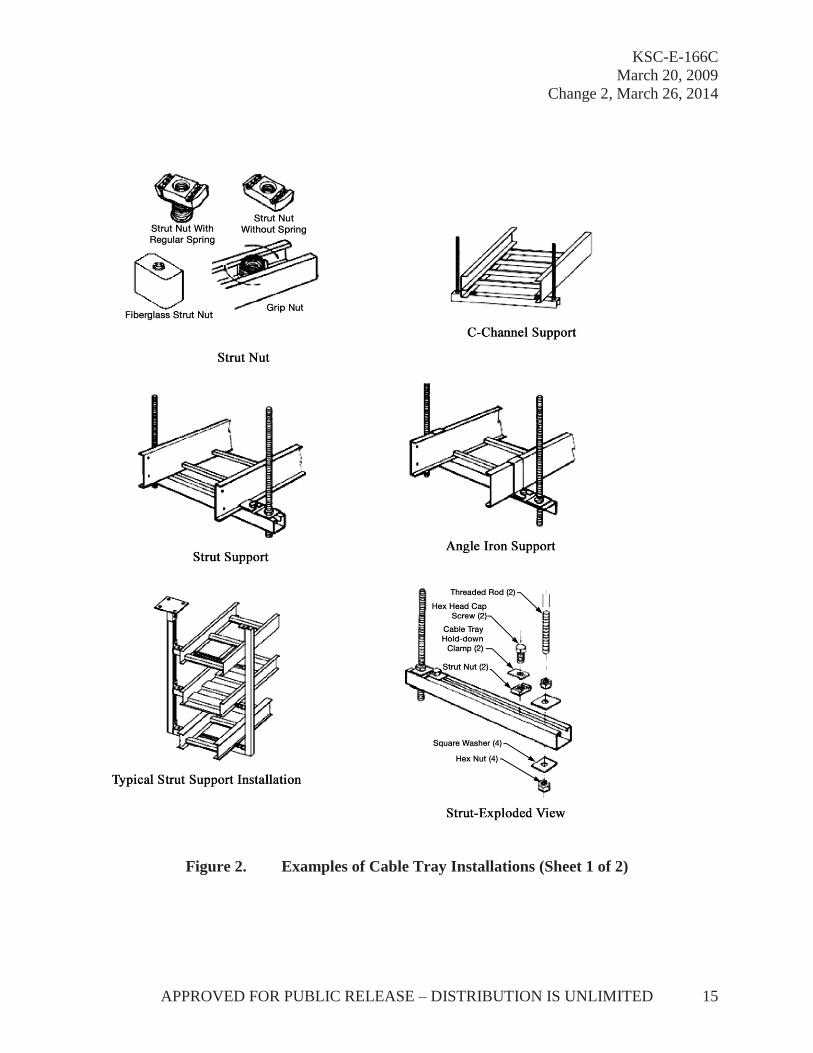
NEMA VE 2 is intended as a practical guide for the proper installation of metal cable tray sys-tems in the United States. Cable tray systems designed for installation at KSC shall comply with NEMA VE 2 and Article 392 of NFPA 70, National Electrical Code (NEC), and follow safe work practices as described in NFPA 70. Figure 2 (two sheets) provides examples of cable tray installations. NFPA 70 states that a cable tray system is to be electrically continuous but does not have to be mechanically continuous. This is an important consideration in installing cable tray systems safely and economically. The gap between sections is restricted to 1.8 m (6 ft), the ca-bles shall be fastened to the cable tray prior to and after the transition, and they shall be protected by a guard or by virtue of their location. The electrical connection between segments shall be maintained with properly sized bonding jumpers or ground wire. (See 3.12.2 for a discussion of grounding cable trays and Figure 7, Example C, for an illustration of a discontinuous cable tray.)
Every effort shall be made to ensure the mechanical continuity of installed cable trays in order to ensure installed cables are not damaged as a result of launch-induced forces. See NEMA VE 2 for extensive instructions and illustrations for cable tray installation.
3.11.4.1 Cable Tray Penetrations
Cable trays shall be permitted to extend transversely through partitions and walls or vertically through platforms and floors in wet or dry locations where the installations, complete with in-stalled cables, shall be made in accordance with NFPA 70, Article 300.21. Cable trays and/or ca-ble penetrations through partitions, walls, floors, and ceilings often require a special fire rating or cause environmental concerns and shall be handled in accordance with NFPA 70, Articles 392 and 300. Figure 3 provides examples of a vertical cable tray penetration. (Firestopping material is not shown.)
KSC-E-166C March 20, 2009
Change 2, March 26, 2014
APPROVED FOR PUBLIC RELEASE – DISTRIBUTION IS UNLIMITED 15
Figure 2. Examples of Cable Tray Installations (Sheet 1 of 2)

KSC-E-166C March 20, 2009 Change 2, March 26, 2014
16 APPROVED FOR PUBLIC RELEASE – DISTRIBUTION IS UNLIMITED
Figure 2. Examples of Cable Tray Installations (Sheet 2 of 2)

KSC-E-166C March 20, 2009
Change 3, November 6, 2014
APPROVED FOR PUBLIC RELEASE – DISTRIBUTION IS UNLIMITED 17
Using Cable Tray-to-Box/Floor Splice Plates Using Cable Tray-to-Box Connector
Figure 3. Vertical Cable Tray Penetration (Firestopping Material Not Shown)
3.11.5 Equipment Racks and Enclosures
Equipment racks and enclosures installed at KSC shall comply with the requirements of KSC-SPEC-E-0002 and EIA-310. Racks and enclosures shall meet all required NEC standards for intrinsic safety as defined by NFPA 70, Section 500 and shall comply with hazardproofing, ignitionproofing, and purging requirements outlined in KSC-E-165, KSC-STD-E-0002, and ap-plicable sections of KSC-DE-512-SM.
3.11.6 Wire, Cable, and Fiber Optics
3.11.6.1 Support in Cabinets, Racks, and Enclosures and in Nonvertical Raceways and Cable Trays
GSE wire and cable routed in cabinets, racks, and enclosures and in nonvertical cable trays raceways shall be installed in compliance with the requirements specified in this document and those specified in KSC-STD-E-0022, NFPA 70, and applicable engineering drawings and documentation. GSE wiring and cabling of similar circuit classification shall be bundled, routed together, and isolated from wiring and cabling of other circuit classifications through mechanical means such as physical separation, routing in cable trays, or shielding. In addition, wire and cable bundles shall be grouped according to system, function (i.e., power, communication, or data), and redundancy requirements. When a physical separation cannot be achieved, a metallic channel separation shall be used, provided the channel separator height is no less than the largest cable or bundle requiring separation. To minimize magnetic coupling effects, bundles of cables with different classifications shall be installed so that the crossovers of these bundles are made at right angles. At junction boxes, terminal strips, panels, or any other location approved by engineering personnel cognizant in electromagnetic compatibility (EMC), the wire harnesses and

KSC-E-166C March 20, 2009 Change 2, March 26, 2014
18 APPROVED FOR PUBLIC RELEASE – DISTRIBUTION IS UNLIMITED
cables may be grouped into a single bundle for short distances, i.e., 305 mm (12 in) nominal. This grouping may be done without regard to signal level, provided the runs do not contain critically redundant circuits.
3.11.6.2 Support in Vertical Cable Raceways and Cable Tray
a. NFPA 70 defines a raceway as “an enclosed channel of metallic or nonmetallic materials designed expressly for holding wires, cables, or busbars, with additional functions as permitted in this Code.” Wire and cable support in vertical cable raceways shall be in accordance with NFPA 70, Section 300.19 and Table 300.19A. Any one method or combination of methods for supporting cable/wire in vertical raceways in accordance with NFPA 70, Section 300.19(C), shall be used to secure cables/wires in vertical raceways, using the spacing intervals defined in NFPA 70, Section 300.19(A) and Table 300.19(A). Those methods include the use of clamping devices, boxes in which insulating supports (e.g., Kellem grips) “…are installed and secured in a satisfactory manner to withstand the weight of the conductors,” junction boxes to deflect cables not less than 90 degrees, and methods of equal effectiveness (e.g., plastic or stainless-steel tie wraps). The use of stainless-steel tie wraps to secure cable/wire bundles shall require the use of a cushioning sleeve installed between the cable/wire bundle and the cable ties or the use of nylon-coated stainless-steel cable ties to prevent vibration from cutting or chafing the cable jacket. Plastic or stainless-steel cable ties shall be installed in accordance with NEMA VE 2, Figure 4-7, which shows the diagonal installation of the cable tie across the cable bundle and around the supporting member. A second cable tie shall be installed in the opposite direction of the first tie at the same location, resulting in a cross-tie or x-configuration for the cable ties installed at each support location. In addition, all plastic or stainless-steel cable ties shall be installed with an installation and cutting tool (e.g., a controlled-tension tie wrap gun) specifically designed for use with the plastic or stainless-steel cable ties being installed. The tension on the installation tool shall be adjustable and shall be set for each cable tie installed as recommended by the tool’s manufacturer.
b. NFPA 70 defines a cable tray system as “a unit or assembly of units or sections and associated fittings forming a structural system used to securely fasten or support cables and raceways.”
(1) Table 392.10(A) lists the wiring methods permitted for installation in cable tray systems and stresses the fact that the cables shall be installed “under the conditions described in their respective articles and sections.” Article 501, Section 501.10 further delineates the types of cables permitted for installation in hazardous areas. Along with wiring methods, the types of cables permitted by Section 501.10 include the following:
(a) power-limited tray cable (PLTC),

KSC-E-166C March 20, 2009
Change 2, March 26, 2014
APPROVED FOR PUBLIC RELEASE – DISTRIBUTION IS UNLIMITED 19
(b) instrumentation tray cable (ITC),
(c) metal-clad (MC) cable,
(d) mineral-insulated (MI) cable,
(e) medium-voltage (MV) cable,
(f) tray cable (TC), and
(g) optical-fiber cable types OFNP, OFCP, OFNR, OFCR, OFNG, OFCG, OFN, and OFC.
(2) Wire and cable support in vertical cable trays shall be in accordance with NFPA 70, Section 392.30, which specifies the following:
(a) In other than horizontal runs, cables shall be securely fastened to traverse members.
(b) Supports shall be provided to prevent stress on cables.
(c) The system shall provide support of cables in accordance with their corresponding articles.
(3) The corresponding articles in NFPA 70 for cables permitted for installation in hazardous areas and the required maximum spacing interval of supports are as follows:
Cable NFPA 70 Article
Max Interval
PLTC 725 1.8 m (6 ft) ITC 727 1.8 m (6 ft) MC 330 1.8 m (6 ft) MI 332 1.8 m (6 ft) MV 328 1.8 m (6 ft) TC 336 1.8 m (6 ft) Optical-fiber cable trays (OFNP, OFCP, OFNR, OFCR, OFNG, OFCG, OFN, OFC)
770 1.2 m (4 ft)

KSC-E-166C March 20, 2009 Change 3, November 6, 2014
20 APPROVED FOR PUBLIC RELEASE – DISTRIBUTION IS UNLIMITED
(4) Specifics regarding the method of supporting identified cables in vertical cable trays can be found in the applicable articles. In general, excluding fiber-optic cables, cables shall be secured by hardware, including straps, staples, cable ties, hangers, or similar fittings, designed and installed so as not to damage the cable. The use of stainless-steel tie wraps to secure cable/wire bundles shall require the use of a cushioning sleeve installed between the cable/wire bundle and the cable ties or the use of nylon-coated stainless-steel cable ties to prevent vibration from cutting or chafing the cable jacket. Plastic or stainless-steel cable ties shall be installed in accordance with NEMA VE 2, Figure 4-7, which shows the diagonal installation of the cable tie across the cable bundle and around the supporting member. A second cable tie shall be installed in the opposite direction of the first tie at the same location, resulting in a cross-tie or x-configuration for the cable ties installed at each support location. In addition, all plastic or stainless-steel cable ties shall be installed with an installation and cutting tool (e.g., a controlled-tension tie wrap gun) specifically designed for use with the plastic or stainless-steel cable ties being installed. The tension on the installation tool shall be adjustable and shall be set for each cable tie installed as recommended by the tool’s manufacturer.
(5) Fiber-optic cables are supported through the use of nonmetallic cable ties and other nonmetallic cable accessories. Care must be taken not to damage or dent the cable jacket. Support can be provided by cable ties (tightened snugly, not tightly enough to deform the cable jacket) or other suitable strain relief grip devices.
c. Additional requirements for the installation of cable in cable tray systems, including cable tray fill, spacing, and ampacity requirements, are found in the applicable articles for each cable type and in NFPA 70, Article 392.
3.11.6.3 Fiber-Optic Cables
Installation of fiber-optic cables shall be in accordance with NASA-STD-8739.5 and NECA/FOA 301.
Fiber-optic cable terminations and assembly shall be in accordance with NASA-STD-8739.5 and KSC-E-165.
Fiber-optic cable testing shall be in accordance with NASA-STD-8739.5 and KSC-E-165.
3.11.6.4 Thermal Protection
When specified, thermal protection of cable assemblies shall be in accordance with engineering drawings and KSC-E-165, section 3.11.9.

KSC-E-166C March 20, 2009
Change 3, November 6, 2014
APPROVED FOR PUBLIC RELEASE – DISTRIBUTION IS UNLIMITED 21
3.11.7 Penetrations
NFPA 70, Section 300.21, specifies that electrical installations in hollow spaces, vertical shafts, and ventilation or air-handling ducts shall be made so that the possible spread of fire or products of combustion will not be substantially increased. Openings around electrical penetrations through walls, partitions, floors, or ceilings that are rated for fire resistance shall be firestopped using approved methods to maintain the fire resistance rating. Directories of electrical construc-tion materials published by qualified testing laboratories contain many listings of installation re-strictions necessary to maintain the fire-resistive rating of assemblies when penetrations or open-ings are made.
Firestop systems and devices are required in accordance with NFPA 101 (Life Safety Code), Section 8.3.5.1, on penetrations for cables, cable trays, conduits, pipes, tubes, combustion vents and exhaust vents, wires, and similar items to accommodate electrical, mechanical, plumbing, and communications systems that pass through a wall, floor, or floor/ceiling assembly con-structed as a fire barrier. The firestop system or device shall be tested in accordance with ASTM E814, or UL 1479, at a minimum positive pressure differential of 2.5 pascals (Pa) (0.01 in water column) between the exposed and the unexposed surface of the test assembly.
The requirements of NFPA 101, Section 8.3.5.1, shall not apply where otherwise permitted by any one of the following:
a. Where penetrations are tested and installed as part of an assembly tested and rated in accordance with NFPA 251, ASTM E119, or UL 263.
b. Where penetrations through floors are enclosed in a shaft enclosure designed as a fire barrier.
c. Where concrete, grout, or mortar has been used to fill the annular spaces around cast-iron, copper, or steel piping that penetrates one or more concrete or masonry fire resistance-rated assemblies and both of the following criteria are also met:
(1) The nominal diameter of each penetrating item shall not exceed 150 mm (6 in), and the opening size shall not exceed 0.09 m2 (1 ft2).
(2) The thickness of the concrete, grout, or mortar shall be the full thickness of the assembly.
d. Where firestopping materials are used with the penetrating items in NFPA 101, Sections 8.3.5.1.1(1) through 8.3.5.1.1(3), and both of the following criteria are also met:
(1) The penetration shall be limited to only one floor.
KSC-E-166C March 20, 2009 Change 3, November 6, 2014
22 APPROVED FOR PUBLIC RELEASE – DISTRIBUTION IS UNLIMITED
(2) The firestopping material shall be capable of preventing the passage of flame and hot gases sufficient to ignite cotton waste when subjected to the time-temperature fire conditions of NFPA 251, ASTM E119, or UL 263 under a minimum positive pressure differential of 2.5 Pa (0.01 inch water column) at the location of the penetration for the time period equivalent to the required fire-resistance rating of the assembly penetrated.
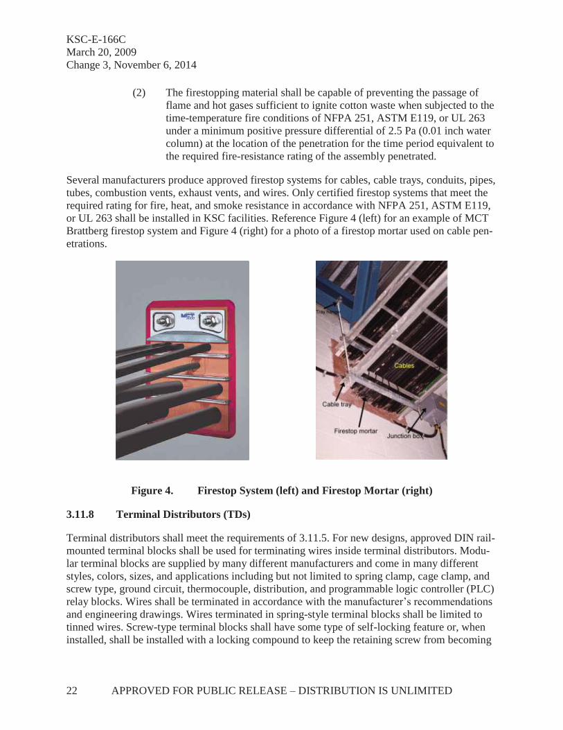
Several manufacturers produce approved firestop systems for cables, cable trays, conduits, pipes, tubes, combustion vents, exhaust vents, and wires. Only certified firestop systems that meet the required rating for fire, heat, and smoke resistance in accordance with NFPA 251, ASTM E119, or UL 263 shall be installed in KSC facilities. Reference Figure 4 (left) for an example of MCT Brattberg firestop system and Figure 4 (right) for a photo of a firestop mortar used on cable pen-etrations.
Figure 4. Firestop System (left) and Firestop Mortar (right)
3.11.8 Terminal Distributors (TDs)
Terminal distributors shall meet the requirements of 3.11.5. For new designs, approved DIN rail-mounted terminal blocks shall be used for terminating wires inside terminal distributors. Modu-lar terminal blocks are supplied by many different manufacturers and come in many different styles, colors, sizes, and applications including but not limited to spring clamp, cage clamp, and screw type, ground circuit, thermocouple, distribution, and programmable logic controller (PLC) relay blocks. Wires shall be terminated in accordance with the manufacturer’s recommendations and engineering drawings. Wires terminated in spring-style terminal blocks shall be limited to tinned wires. Screw-type terminal blocks shall have some type of self-locking feature or, when installed, shall be installed with a locking compound to keep the retaining screw from becoming

KSC-E-166C March 20, 2009
Change 3, November 6, 2014
APPROVED FOR PUBLIC RELEASE – DISTRIBUTION IS UNLIMITED 23
loose due to vibration or stress placed on the terminal block or wire(s). Cables and wires in-stalled in terminal distributors shall be supported to their respective terminal-block mounting channels. Supports shall be spaced a maximum of 150 mm (6 in) on center, with a support lo-cated immediately adjacent to and on each side of the breakout of the conductors from the cable. Supports shall be similar to self-locking tie-straps or an approved similar product and shall be securely bolted to the mounting surface. Care shall be taken not to have any of the individual ca-ble shields or the conductor shields grounded to the terminal distributor frame, especially at the points of cable supports. Where cables with individually shielded conductors or pairs are termi-nated on terminal blocks, the terminal-block mounting channel shall be adequately insulated to maintain the isolation of the shields from ground.
3.11.9 Glands and Cable Termination Fittings
Glands and cable termination fittings are used when typical connector terminations are not practical. Glands and cable termination fittings provide a means for passing armored, metal-clad, jacketed cable through a bulkhead or enclosure. Glands and fittings shall be selected based on cable type, environmental conditions, EMC requirements, and material compatibility. Glands and fittings shall be installed in accordance with the manufacturer’s specifications.
3.12 Grounding and Bonding
Grounding and bonding of equipment shall be in accordance with the requirements of KSC-STD-E-0022 for ground systems (including bonding wires, ground bars and structure), KSC-STD-E-0012 for facility systems and earth ground (including connections to the earth counterpoise), and NFPA 70, Articles 250, 392.7, 640.7, and 647.6, along with the NFPA 70E, Sections 235.2,110.9(B)(2) and 320.3(F). MIL-HDBK-419 and MIL-HDBK-1857 contain best practices for grounding, bonding, and shielding for electronic equipment and facilities and should be consulted as guides for proper grounding, bonding, and shielding. All exposed non-current-carrying metallic parts of electrical equipment and conduit systems shall be grounded. All grounding surfaces on such items as motor and equipment frames, cable trays, starters and contactors, junction boxes, consoles, racks, and conduit shall be thoroughly cleaned to the conductive finish before applying the ground clamp or lug. The grounding surface of terminal lugs shall be free of dirt, grease, or any other foreign matter that would create a high-resistance contact. The grounding surface shall be metallic and of low enough resistance to meet the 2.5-milliohm (mΩ) requirement listed later in this section, with no paint oxides or insulating finish. Ground lugs that are pitted or deformed shall not be used. If the existing ground pads are rough or pitted, the contractor shall finish the surfaces of these pads until they are smooth and flat. Before the assembly and tightening of ground clamps and pads, the clamps and pads, including the contact surfaces, shall be thoroughly covered with a silicone compound in accordance with SAE AS8660 to exclude air and moisture.
A sheet metal strap-type ground clamp that is used on the grounding conductor of a wiring sys-tem must be made of a material that will prevent the clamp from stretching during or after installation, and it must be installed in a manner that will prevent the clamp from stretching. In

KSC-E-166C March 20, 2009 Change 3, November 6, 2014
24 APPROVED FOR PUBLIC RELEASE – DISTRIBUTION IS UNLIMITED
addition, the clamp must be attached to a rigid metallic base connected to an equipment ground or another suitable electrode. Ground clamps and fittings shall be protected from mechanical in-jury by being placed where they are unlikely to be damaged or by being enclosed in a protective covering (made of metal, wood, or an equivalent material) that can be removed so that the items can be inspected, unless there is approval to use the clamps or fittings without protection.
Table 1 indicates the acceptable methods of making connections between bonding jumpers and structures of various metals. The metals are listed in order of decreasing activity in salt water; the higher metal in the series will be the one attacked when there is galvanic action between any two. In general, the greater the separation between any two of the metals, the more pronounced the corrosive activity will be. When either a Type I or Type II screw is indicated as acceptable, the Type II screw is preferable from a corrosion resistance standpoint and shall be used in corrosive environments.
Table 1. Metal Connections
Metal Structure (Outer Finish Metal)
Connection for Aluminum Jumper
Connection for Tinned Copper Jumper
Magnesium and Mg-based al-loy
Direct or Mg washer Type I* screw Al or Mg washer Type I screw
Zinc, cadmium, aluminum, and Al alloys
Direct Type I screw Al washer Type I screw
Steel (except stainless steel) Cadmium-plated washer Type I screw Direct Type I screw Tin, lead, and Pb-Sn solders Cadmium-plated washer Type I screw Direct Type I or II**
screw Copper and Cu-based alloys Tinned or
cadmium-plated washer Type I or II screw
Direct Type I or II screw
Nickel and Ni-based alloys Tinned or cadmium-plated washer
Type I or II screw
Direct Type I or II screw
Stainless steel Tinned or cadmium-plated washer
Type I or II screw
Direct Type I or II screw
Silver, gold, and other noble metals
Tinned or cadmium-plated washer
Type I or II screw
Direct Type I or II screw
* Type I: zinc-plated or cadmium-plated **Type II: stainless steel
All grounding connections shall be exothermic fusion-welded, except when bolted connections are indicated on the drawings. Soldered ground connections are not permitted. All connectors shall be specifically designed for grounding, with adequate protection against corrosion and where a connection is made to dissimilar metals, the joined members, as well as the connector, shall be protected against electrolysis. All ground connections below grade shall be painted with a heavy coat of bitumastic paint and shall be inspected and approved by the contracting officer before backfill. Figure 5 presents examples of exothermic fusion welds.

KSC-E-166C March 20, 2009
Change 2, March 26, 2014
APPROVED FOR PUBLIC RELEASE – DISTRIBUTION IS UNLIMITED 25
Figure 5. Typical Bond Configurations Implemented With an Exothermic Process
Grounding taps shall be as short as possible and shall be run in conduit where mechanical protec-tion may be necessary. When existing ground taps are not long enough to be installed properly, they shall be extended with conductors of the same size and type. Such extensions to existing ground taps shall be made by exothermic fusion welding only.
Conduit entering or leaving junction boxes shall be properly grounded by means of ground clamps or ground bushings. Where conduit enters or leaves an enclosure through a concentric knockout, the conduit shall be bonded across the knockout.
Pressure-type lugs, clamps, and split-bolt connectors shall be sufficiently tight to meet resistance requirements as specified by the manufacturer. The controlling points for measuring resistance shall be within the limits of the cleaned area to be bonded, on the jumper terminal within 6.4 mm (0.25 in) of the exterior, or at that point called for on the drawings. The resistance shall be measured between the jumper terminal and the object or structure to which it is attached using a milliohmmeter and either shall not exceed 2.5 mΩ or shall meet the requirements specified by the contracting officer.

KSC-E-166C March 20, 2009 Change 2, March 26, 2014
26 APPROVED FOR PUBLIC RELEASE – DISTRIBUTION IS UNLIMITED
3.12.1 Grounding of Wire and Cable Shields
Proper grounding of structures and equipment shall be maintained for the safe and efficient oper-ation of communication and data handling networks and facilities at KSC in accordance with KSC-STD-E-0012 for facility systems and KSC-STD-E-0022 for ground systems. Likewise, bonding/grounding of wire and cable shields installed in KSC facilities is also critical for the fol-lowing three reasons:
a. Personnel safety. To provide for the safety of personnel, low-impedance ground-ing and bonding are used between equipment, metallic objects, piping, and other conductive objects, so that currents from faults, lightning, or high-voltage transi-ents do not result in voltages sufficient to cause a shock hazard and/or arc flash hazard.
b. Equipment and facility protection. To protect equipment and facilities, low- impedance grounding and bonding are used between electrical services, protective devices, equipment, and other conductive objects, so that faults or lightning cur-rents do not result in hazardous voltages within the facility. Also, the proper oper-ation of overcurrent protective devices is frequently dependent upon low- impedance fault current paths.
c. Electrical noise reduction. Electrical noise shall be reduced on communication circuits by ensuring that (1) minimum voltage potentials exist between communi-cations and electronics equipment, (2) the impedance between signal ground points to earth is minimal throughout the facility, and (3) interference from noise sources is minimized.
3.12.1.1 Overall Shields
In accordance with KSC-E-165, overall shields installed on GSE and facility wire/cable runs shall be electrically bonded 360 degrees at each connector end of every wire/cable run. The elec-trical bond shall be maintained through the connector shell to the outside of every interfacing structure and enclosure to facilitate either a single-point or multipoint grounding system as de-fined by the system design and as specified in engineering drawings. The proper bonding and grounding of the overall shields to the cable plant will minimize ground loops and establish a safe and relatively noise-free operating environment. Figure 6 illustrates one proper implementa-tion of overall shield grounding.
3.12.1.2 Internal/Individual Shields
Internal shields on individually twisted pairs of wires shall be terminated as specified in the engi-neering drawings.

KSC-E-166C March 20, 2009
Change 2, March 26, 2014
APPROVED FOR PUBLIC RELEASE – DISTRIBUTION IS UNLIMITED 27
Figure 6. Implementing Overall Shield Grounding
3.12.1.3 Current-Carrying Shields
Any shield that is used as a current-carrying path shall not be connected to the overall shield or to the exterior of any enclosure, cabinet, or electrical GSE. Refer to engineering drawings for the correct installation of wires/cables with current-carrying shields.
3.12.2 Grounding of Cable Trays
Metal cable trays shall be grounded and be electrically continuous systems in accordance with KSC-STD-E-0012 and NFPA 70, Article 392.7. See Figure 7 (examples A through D) for spe-cific areas requiring bonding for electrical continuity. The use of aluminum and steel cable trays is permitted as an equipment grounding conductor (EGC) in accordance with NFPA 70, Arti-cle 392, when labeled and marked within the available cross-sectional area. If the cable tray is to be used as an EGC, bonding jumpers must be installed on both side rails at the locations illus-trated in examples A through D, unless the splice plates meet the electrical continuity require-ments of NEMA VE 1. If the connectors are UL-classified, it is not necessary to use bonding jumpers or a continuous ground. It is not necessary to install bonding jumpers at standard rigid aluminum or galvanized steel splice plate connections or offset reducing splice plate connections or any UL-classified connectors. For rigid splice plate connections of materials and finishes other than aluminum or galvanized steel, bonding jumpers may be required. For example, stainless steel splice plates may require bonding jumpers depending upon their UL classification.

KSC-E-166C March 20, 2009 Change 2, March 26, 2014
28 APPROVED FOR PUBLIC RELEASE – DISTRIBUTION IS UNLIMITED
Figure 7. Installation of Cable Tray Grounds
3.12.3 Grounding of Equipment Racks
Racks and cabinets shall be bonded to the nearest point of the equipotential plane. Each individ-ual unit or piece of equipment should either be bonded to its rack or cabinet or have its case or chassis bonded to the nearest point on the equipotential plane. Bonding between the equipment chassis and the rack shall be achieved through a contact between the equipment panels and the rack brackets or electrical bond strap. The brackets shall be bonded to the rack frame. A ground stud shall be provided on the rack to interconnect the rack structure to the facility ground system. Figure 8 shows a typical bonding scheme for racks/enclosures. Where hinges are used, an alter-nate electrical path shall be established by using thin, flexible straps across the hinges. Figure 9 illustrates a proper grounding/bonding configuration for the equipment, enclosure, panel, and ca-ble tray. Standard MS-type connectors and coaxial connectors must be bonded to their respective panels over the entire mating surfaces as illustrated in Figure 10. Panel surfaces must be cleaned to the base metal for no less than 0.32 cm (1/8 in) beyond the periphery of the mating connector.

KSC-E-166C March 20, 2009
Change 2, March 26, 2014
APPROVED FOR PUBLIC RELEASE – DISTRIBUTION IS UNLIMITED 29
Figure 8. Typical Bonding Scheme for Racks/Enclosures

KSC-E-166C March 20, 2009 Change 2, March 26, 2014
30 APPROVED FOR PUBLIC RELEASE – DISTRIBUTION IS UNLIMITED
Figure 9. Equipment Enclosure, Panel, and Cable Tray Grounding/Bonding Configuration
Figure 10. Bonding of Connector to Mounting Surface of Rack/Enclosure

KSC-E-166C March 20, 2009
Change 3, November 6, 2014
APPROVED FOR PUBLIC RELEASE – DISTRIBUTION IS UNLIMITED 31
3.12.4 Bonding and Grounding of Launch Accessary Assemblies (Arms and Umbilicals)
Launch accessory assemblies (arms and umbilicals) may be susceptible to carrying lightning-in-duced current or may generate a static charge. Bonding and grounding of launch accessories shall be in accordance with KSC-STD-E-0022.
The following information should be used as guidelines for bonding and grounding of fluid lines, equipment, and structures:
a. All bonding and grounding cables shall appear in the parts list on engineering drawings.
b. Additional engineering drawings may be required:
(1) kit drawings for straps used during installation, and
(2) assembly drawings for bonding between subassemblies.
c. Most straps should be terminated with terminal eye lugs for installation under the head of a bolt.
d. For permanent bonding straps/cables, thermite welds (CadWeld) should be used where the bonding straps are to be attached to a steel structure.
e. Bonding impedance shall be 2.5 mΩ or less. Bonding impedance of 10 mΩ or less is acceptable for stainless-steel alloy bonding.
f. The impedance measurement shall be made across the bond (i.e., from the bond at one end of the bonding strap to the bond at the other end of the bonding strap).
g. Floor grating or screening that may have drag on electrical cables or extension cords shall be grounded.
(1) Mounting hardware is an acceptable method of bonding and grounding, provided that the surface is clean prior to mounting.
(2) Field welding is an acceptable method of bonding and grounding.
h. Permanent and temporary handrails shall be grounded.
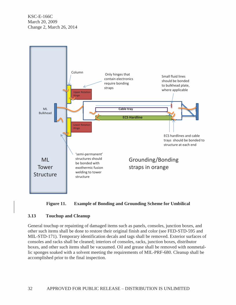
KSC-E-166C March 20, 2009 Change 2, March 26, 2014
32 APPROVED FOR PUBLIC RELEASE – DISTRIBUTION IS UNLIMITED
Figure 11. Example of Bonding and Grounding Scheme for Umbilical
3.13 Touchup and Cleanup
General touchup or repainting of damaged items such as panels, consoles, junction boxes, and other such items shall be done to restore their original finish and color (see FED-STD-595 and MIL-STD-171). Temporary identification decals and tags shall be removed. Exterior surfaces of consoles and racks shall be cleaned; interiors of consoles, racks, junction boxes, distributor boxes, and other such items shall be vacuumed. Oil and grease shall be removed with nonmetal-lic sponges soaked with a solvent meeting the requirements of MIL-PRF-680. Cleanup shall be accomplished prior to the final inspection.
Grounding/Bonding straps in orange
ECS Hardline
Upper Rotation Hinge
Lower Rotation Hinge
ML Tower
Structure
ML Bulkhead
Small fluid lines should be bonded to bulkhead plate, where applicable
ECS hardlines and cable trays should be bonded to structure at each end
Cable tray
‘semi-permanent’ structures should be bonded with exothermic fusion welding to tower structure
Column Only hinges that contain electronics require bonding straps
KSC-E-166C March 20, 2009
Change 3, November 6, 2014
APPROVED FOR PUBLIC RELEASE – DISTRIBUTION IS UNLIMITED 33
4. QUALITY ASSURANCE PROVISIONS
The supplier shall be responsible for the performance of all inspection and test requirements specified in the design or contract specification and as specified herein. Except as otherwise specified, the supplier may use its own or any other inspection and test facilities and services ac-ceptable to NASA. Inspection and test records shall be kept complete and, upon request, shall be made available to the contracting officer. (See Appendix A for sample inspection sheet forms.) The contracting officer reserves the right to perform any or all of the inspections and tests set forth in the specification to ensure that the end item conforms to the prescribed requirements. In-spection, testing, and validation of installed cables, GSE assemblies, and subsystems shall be conducted by the contracting officer or his/her designated representatives. Tests on cable/wire installations in particular shall include, at a minimum, visual inspections and any continuity, die-lectric withstanding voltage (DWV)/Hipot testing and insulation resistance (IR)/megohmmeter testing prescribed in applicable engineering or validation documentation.
5. PREPARATION FOR DELIVERY
There are no applicable requirements.
6. NOTES
6.1 Intended Use
This specification is intended for use by contractors in the installation and assembly of electrical ground support equipment. This specification is also intended for use by the Engineering and Technology Directorate to ensure all requirements and specifications for assembly and installa-tion of electrical GSE are accomplished as established in written contract(s) and engineering drawings. In addition to other available resources, the Engineering and Technology Directorate shall use Appendix B, Design Engineering Checklist, as a guide when preparing engineering drawings, documentation, and contracts.
6.2 Definitions
For the purpose of this specification, the following definition shall apply:
Short signs: Used to designate a component without giving complete reference designation; i.e., resistor R1 within enclosure 5601 would be “R1” instead of “5601 R1.”
6.3 Notice
The Government drawings, specifications, and/or data are prepared for the official use by, or on the behalf of, the United States Government. The Government neither warrants these Government drawings, specifications, or other data, nor assumes any responsibility or obligation, for their use for purposes other than the Government project for which they were prepared and/or provided by the Government, or an activity directly related thereto. The fact that the Government

KSC-E-166C March 20, 2009 Change 3, November 6, 2014
34 APPROVED FOR PUBLIC RELEASE – DISTRIBUTION IS UNLIMITED
may have formulated, furnished, or in any way supplied the said drawings, specifications, or other data is not to be regarded, by implication or otherwise, as licensing in any manner the holder or any other person or corporation, nor conveying the right or permission, to manufacture, use, or sell any patented invention that may relate thereto.
Custodian:
Preparing Activity:
NASA – John F. Kennedy Space Center Kennedy Space Center, Florida 32899
John F. Kennedy Space Center Engineering and Technology Directorate Electrical Division

KSC-E-166C March 20, 2009
Change 2, March 26, 2014
APPROVED FOR PUBLIC RELEASE – DISTRIBUTION IS UNLIMITED 35
APPENDIX A. SAMPLE INSPECTION CHECKLIST
Dwg/Code Item of Work Checkpoint Approved Rejected Signature
GROUNDING
(a) CHECK CONNECTIONS FOR TIGHTNESS AND CORRECT FITTINGS
(b) CHECK GROUND SURFACES FOR COMPOUND COATING
(c) CHECK EQUIPMENT, ETC., FOR GROUND CONNECTIONS
(d) CHECK ISOLATED CONDUIT FOR GROUNDING
MOTOR STARTER
(a) CONTROL TRANSFORMER – SIZE, VOLTAGE
(b) COIL VOLTAGE (c) THERMAL OVERLOAD RELAYS –
HEATER SIZE
(d) LOCATION (e) INSTALLATION (f) CONDUIT TERMINATIONS (g) CABLE TERMINATIONS (h) TAP PERCENT SETTING (i) GROUNDING (j) OPERATION (k) CONTACTS CLEAN Checked by Contractor Date NASA
Approved Date

KSC-E-166C March 20, 2009 Change 2, March 26, 2014
36 APPROVED FOR PUBLIC RELEASE – DISTRIBUTION IS UNLIMITED
Dwg/Code Item of Work Checkpoint
Approved Rejected Signature DXXXXXXX POWER SUPPLY (PURCHASED ITEM) (a) SHEET METAL DETAILS (b) SHEET METAL ASSEMBLY (c) PANEL FINISH AND SILKSCREEN (d) ELECTRICAL COMPONENTS
INSTALLATION
(e) WIRE ROUTING AND INSTALLATION (f) WIRE TERMINATIONS (g) ELECTRICAL RINGOUT (h) ACCEPTANCE CHECKOUT PROCEDURE (i) FINISH D75XXX-XX HARNESS ASSEMBLY (37XXXX) 35 FT (a) CORRECT LENGTH (b) CORRECT TERMINATORS –
CONNECTOR, LUG, SHIELDING
(c) CONNECTOR PIN AND SOCKETS – FREE OF DEFECTS AND IMPERFECTIONS
(d) IDENTIFICATION (e) INSTALLATION (f) TERMINATIONS – EQUIPMENT (g) TESTING-ISOLATING (CABLES
DISCONNECTED FROM COMPONENTS)
(h) CABLE FREE OF DEFECTS AND IMPERFECTIONS
Checked by Contractor Date NASA Approved
Date

KSC-E-166C March 20, 2009
Change 2, March 26, 2014
APPROVED FOR PUBLIC RELEASE – DISTRIBUTION IS UNLIMITED 37
Dwg/Code Item of Work Checkpoint
Approved Rejected Signature JXXXXXXX PANEL DISTRIBUTOR (a) SHEET METAL DETAILS (b) SHEET METAL ASSEMBLY (c) TERMINAL BOARD ASSEMBLY (d) ELECTRICAL COMPONENTS
INSTALLATION
(e) WIRE ROUTING AND INSTALLATION
(f) WIRE TERMINATIONS (g) ELECTRICAL RINGOUT (h) ACCEPTANCE CHECKOUT
PROCEDURE
D75XXX-X CABLE ASSEMBLY (55XXXX) 10 FT. (a) CABLE FREE OF DEFECTS AND
IMPERFECTIONS
(b) CABLE LENGTH (c) CORRECT CONNECTOR AND
CONNECTORS
(d) CONNECTOR – SOLDERING (e) POTTING AND MOLDING OF
CONNECTOR AND CONNECTORS
(f) CABLE IDENTIFICATION MARKERS (g) IR and DWV TESTS (h) CONTINUITY CHECK Checked by Contractor Date NASA
Approved Date

KSC-E-166C March 20, 2009 Change 2, March 26, 2014
38 APPROVED FOR PUBLIC RELEASE – DISTRIBUTION IS UNLIMITED
Dwg/Code Item of Work Checkpoint
Approved Rejected Signature JXXXXXXX JUNCTION BOX 59XXX (a) LOCATION (b) INSTALLATION (c) CONDUIT TERMINATION (d) CABLE INSTALLATION (e) JUNCTION BOX FINISH CONDUIT SYSTEM (BASEMENT) (a) CONDUIT FREE OF DEFECTS AND
DEFORMATION
(b) CUTTING CONDUIT – SQUARE ENDS (c) REAM CUT END TO DEBURR AND
REMOVE SHARP EDGES
(d) COAT JOINT WITH RED OR WHITE LEAD
(e) THREADS PULLED UP TIGHT (f) EXCESS LEAD REMOVED AFTER
CONDUIT SCREWED TOGETHER
(g) SUPPORT, TIGHT AND AT SPECI-FIED DISTANCES
(h) CONDUIT TERMINATION WITH DOUBLE LOCKNUT AND INSU-LATED BUSHING (IF REQUIRED)
(i) SMOOTH, WELL-FORMED ENDS Checked by Contractor Date NASA
Approved Date

KSC-E-166C March 20, 2009
Change 2, March 26, 2014
APPROVED FOR PUBLIC RELEASE – DISTRIBUTION IS UNLIMITED 39
APPENDIX B. DESIGN ENGINEERING CHECKLIST
Specify requirements for preparation of EGSE for shipment and/or storage and ensure these re-quirements are addressed in the contract, engineering drawings, and engineering documentation.
Specify requirements for transportation of parts, materials, supplies, and equipment to the instal-lation site.
Specify storage requirements, including but not limited to the following:
a. designated storage area(s),
b. protection of parts, materials, equipment, and supplies at installation site prior to and during installation,
c. any pre- or post-environmental conditioning required,
d. procedures for temperature and/or humidity monitoring and control when and where required,
e. use of portable conditioning units or chemical dehumidifiers (air, heat, humidity), and
f. protective covers to be installed prior to and after installation.
Describe the installation process, including but not limited to the following:
a. defined procedure for turning over EGSE to an installation contractor with spe-cific installation instructions,
b. site safety requirements and certification requirements for local support contractor technicians performing the installation,
c. installation of equipment into existing enclosures,
d. definition, identification, and verification of critical clearances, cable runs, and terminations,
e. procedure for locating, installing, and securing racks and enclosures, including bolting racks together,
f. requirements and procedures for maintaining EMI integrity,
g. requirements and procedures for labeling parts, equipment, cables, racks, assem-blies, and subassemblies,

KSC-E-166C March 20, 2009 Change 2, March 26, 2014
40 APPROVED FOR PUBLIC RELEASE – DISTRIBUTION IS UNLIMITED
h. proper use of and adherence to wiring lists and schematics,
i. reference to circuit isolation devices (CIDs) and use during installation process, and
j. requirements for adherence to all local, state, and Federal standards and specifica-tions (i.e., NFPA, NEC, OSHA, NASA, and KSC).
Define the requirements and/or provide the procedure for connection of the following:
a. power,
b. communications and data,
c. isolation, and
d. safety wiring connectors.
Define postinstallation requirements, including but not limited to the following:
a. verification of proper installation,
b. any postinstallation environmental conditioning and storage requirements,
c. procedures for required continuous temperature and/or humidity monitoring and control,
d. use of portable conditioning units or chemical dehumidifiers (air, heat, humidity),
e. protective covers to be placed after installation,
f. integrity seals,
g. requirements and procedures for validation of proper system operation, and
h. final acceptance by customer.

STANDARDIZATION DOCUMENT IMPROVEMENT PROPOSAL
INSTRUCTIONS
1. The preparing activity must complete blocks 1, 2, 3, and 8. In block 1, both the document number and revision letter should be given.
2. The submitter of this form must complete blocks 4, 5, 6, and 7. 3. The preparing activity must provide a reply within 30 days from receipt of the form. NOTE: This form may not be used to request copies of documents, nor to request waivers or clarification of re-quirements on current contracts. Comments submitted on this form do not constitute or imply authorization to waive any portion of the referenced document or to amend contractual requirements.
I RECOMMEND A CHANGE:
1. DOCUMENT NUMBER
KSC-E-166C, Change 3
2. DOCUMENT DATE
November 6, 2014
3. DOCUMENT TITLE
Installation and Assembly, Electrical Ground Support Equipment (GSE), Specification for
4. NATURE OF CHANGE (Identify paragraph number and include proposed rewrite, if possible. Attach extra sheets as needed.)
5. REASON FOR RECOMMENDATION
6. SUBMITTER
a. NAME (Last, First, Middle Initial)
b. ORGANIZATION
c. ADDRESS (Include Zip Code)
d. TELEPHONE (Include Area Code)
7. DATE SUBMITTED
8. PREPARING ACTIVITY
a. NAME (Last, First, Middle Initial)
Denson, Erik C. b. ORGANIZATION
Engineering and Technology Directorate, Electrical Division
c. ADDRESS (Include zip code)
Kennedy Space Center, FL 32899
KSC FORM 21-610NS (2/94) (C/G 2/94)

REPORT DOCUMENTATION PAGE Form Approved OMB No. 0704-0188
The public reporting burden for this collection of information is estimated to average I hour per response, including the time for reviewing instructions, searching existing data sources, gathering and maintaining the data needed, and completing and reviewing the collection of information. Send comments regarding this burden estimate or any other aspect of this collection of information, including suggestions for reducing this burden, to Department of Defense, Washington Headquarters Services, Directorate for Information Operations and Reports (0704-0188), 1215 Jefferson Davis Highway, Suite 1204, Arlington, VA 22202-4302. Respondents should be aware that notwithstanding any other provision of law, no person shall be subject to any penalty for failing to comply with a collection of information if it does not display a currently valid OMB control number. PLEASE DO NOT RETURN YOUR FORM TO THE ABOVE ADDRESS. 1. REPORT DATE (DD-MM-YYYY)
06-11-2014 2. REPORT TYPE
Technical Publication 3. DATES COVERED (From — To)
4. TITLE AND SUBTITLE
Installation and Assembly, Electrical Ground Support Equipment (GSE), Specification for
5a. CONTRACT NUMBER
5b. GRANT NUMBER
5c. PROGRAM ELEMENT NUMBER
6. AUTHOR(S)
(1) Denson, Erik C.
5d. PROJECT NUMBER
5e. TASK NUMBER
5f. WORK UNIT NUMBER
7. PERFORMING ORGANIZATION NAME(S) AND ADDRESS(ES)
(1) National Aeronautics and Space Administration Kennedy Space Center, FL 32899
8. PERFORMING ORGANIZATION REPORT NUMBER
NASA/TP–2014–218439
9. SPONSORING/MONITORING AGENCY NAME(S) AND ADDRESS(ES)
10. SPONSORING/MONITOR’S ACRONYM(S)
11. SPONSORING/MONITORING REPORT NUMBER
12. DISTRIBUTION/AVAILABILITY STATEMENT Unclassified – Unlimited Distribution: Standard Subject Category: Availability: NASA CASI (301) 621-0390
13. SUPPLEMENTARY NOTES
14. ABSTRACT
This specification covers the general workmanship requirements and procedures for the complete installation and assembly of electrical ground support equipment (EGSE) such as terminal distributors, junction boxes, conduit and fittings, cable trays and accessories, interconnecting cables (including routing requirements), motor-control equipment, and necessary hardware as specified by the applicable contract and drawings.
15. SUBJECT TERMS
specification, workmanship, electrical ground support equipment, EGSE
16. SECURITY CLASSIFICATION OF: 17. LIMITATION OF ABSTRACT
UU
18. NUMBER OF PAGES
58
19a. NAME OF RESPONSIBLE PERSON
Erik C. Denson a. REPORT
U b. ABSTRACT
U c. THIS PAGE
U 19b. TELEPHONE NUMBER (Include area code)
(321) 867-6537 Standard Form 298 (Rev. 8-98) Prescribed by ANSI Std. Z39

