specification for design, realisation and supply of n o ... dimensions and road worthiness of the...
TRANSCRIPT

Page 1 of 21
IPRC/ESPSF/SP/01
Specification for Design, Realisation and Supply of N2O4/UH-25
Propellant Road Tankers
1.0 General:
1.1 Four numbers of road tankers are required for transportation of N2O4/
UH-25 propellants between production plants and ISRO work centers.
The tank of 8m3 water capacity made of AISI 304L is mounted over a
semi trailer with telescopic front and rear supports. The trailer shall be of
18T pay load capacity. Procurement of all materials for fabrication and
realization of the tankers (trailers, tanks materials, components given in
para 11) is the scope of the party except prime movers. The following
details shall be considered during the design and fabrication of the
tankers.
1.2 The fabricator shall have the approval of Chief Controller of Explosives,
Nagpur for the fabrication of pressure vessels under Static and Mobile
Pressure Vessels (unfired) rules 1981.Copy of the current approval shall
be submitted along with the Techno Commercial bid.
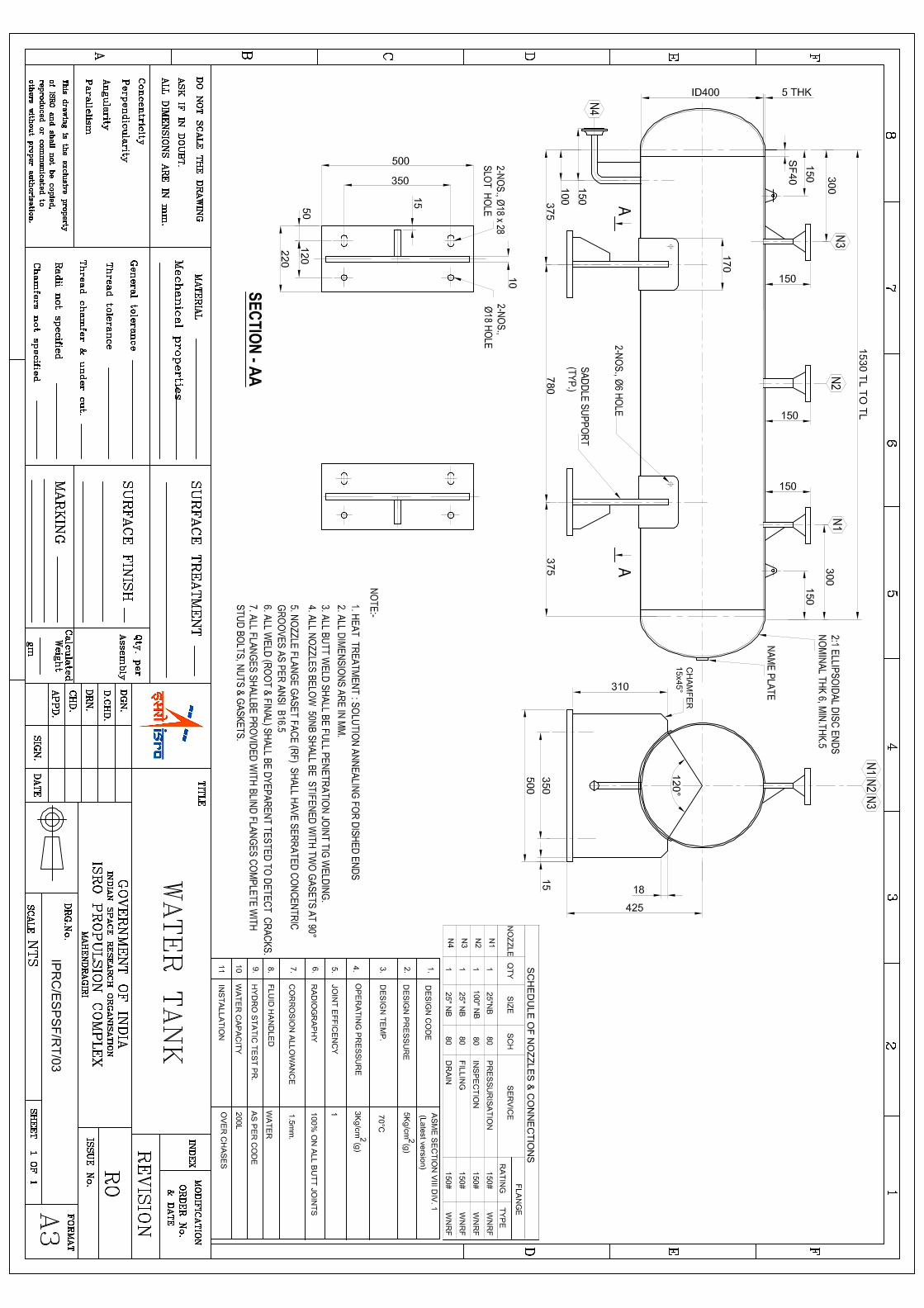
1.3 The fabricator shall design the N2O4/UH-25 propellant tanks and water
tanks based on the enclosed preliminary dimensional drawings
IPRC/ESPSF/RT/01, IPRC/ESPSF/RT/02 and IPRC/ESPSF/RT/03.
1.4 The fabricator shall consider the rules and regulations followed by the
state transport authorities.
1.5 The fabricator should get approval for the following
a) Fabrication drawings, mounting drawings and design calculations for
functional aspects and QAP from IPRC.
b) Fabrication drawings, mounting drawings, design calculations and QAP
from third party inspection agency.
c) Fabrication drawings and mounting drawings from Chief Controller of
Explosives, Nagpur for N2O4 road tankers.

Page 2 of 21
1.6 The overall height of the tanker (Prime mover and trailer in hauled
condition) shall meet the State Transport Authorities (STA) requirement.
1.7 The supplier should get clearance from State transport authorities for
overall dimensions and road worthiness of the tankers.
1.8 The supplier is responsible for temporary registration of the tankers on
the name of Director, IPRC.
1.9 The supplier should arrange to get CCOE license from Nagpur for N2O4
road tankers on the name of Director, IPRC. Obtaining CCOE licenses for
N2O4 road tankers is the responsibility of the supplier.
1.10 Fabrication works shall be taken up only after final approvals.
2.0 Material of construction
Sl.
No. Description Material
1 Shell and Dished ends SA 240 GR 304L
2 Nozzle pipes SA 312 TP 304L (Seamless)
3 Nozzle flanges & blind flanges SA 182 F 304L
4 Man hole flange & blind
flange SA 182 F 304L
5 Baffle plates, reinforcement &
pad/wear plates SA 240 GR 304L
6 Stud bolts/ nuts/ washers SA 193 GR B8/SA 194 GR 8/ SS
7 Gaskets
PTFE & SS 304L spiral wound
with SS 304L inner and outer
rings
8 Man hole cover flange removal
assembly/ Davit arm
SS 304L
9 Lifting lugs, Name plate &
bracket SS 304L

Page 3 of 21
10 Man hole cover (Hood),
Handles SS 304L
11 Ladder & platform supports SS 304L
12 Saddle supports IS 2062
13 Platform Aluminium (chequered)
14 Materials having direct
contact with tanks & fluids
SS 304L
3.0 Tank Specification
Type : Horizontal, Cylindrical with 2:1 ellipsoidal dished ends both sides
Design & : i) ASME Boiler and pressure vessel code Construction Sec. VIII Div.1, latest edition.
ii) During design, wind load for survival wind
speed of 200 km/hr considering 3 sec gust;
operating wind speed of 120 km/hr and
Seismic zone 3 as per IS 1893 shall be
considered.
Working pressure : 4 kg/cm2(g)
Design pressure : 7 kg/cm2 (g) (Including 3g)
Allowance : Corrosion allowance – 3 mm.
Surface treatment allowance – 1 mm.
Suitable allowance for thinning during
forming (rolling/spinning/ pressing) is to be
considered.
Thickness (min) : Shell – 10 mm & Dish end – 12 mm.
including all allowances.
4.0 General requirements
4.1 During design, the design stress selected shall include an allowance to
enable the vessel to withstand shocks normally encountered by

Page 4 of 21
movements on road such as sudden acceleration and deceleration for a
minimum of 3g provision as per Static and Mobile Pressure Vessels
(unfired) rules 1981 shall be made for distributing localized stress arising
from attachments. Two numbers of baffle plates with stiffeners shall be
provided to minimize the slashing of fluid during movements. The baffle
plates should have openings of 400 mm radius at bottom to connect
liquid phase and 200mm radius at top to connect vapour phase of the
compartments.
4.2 Mounting of the vessel on the trailer chassis shall be done in such a
manner so as to keep the vibration to a minimum by using pads made of
balata material, and take care of the forward and backward movements
of the vessel due to sudden acceleration and deceleration.
4.3 The king pin mounted on the trailer is under the scope of fabricator. The
size of the king pin shall be 51mmx73mm long (std.). The raw material
for the king pin shall be ultrasonically tested for any internal defects. The
manufacturer’s chemical and mechanical test certificates shall be
provided for materials used for king pin. Only defect free material shall
be used for machining the pin.
4.4 The vessel shall be mounted on the trailer so as to get an inclination of
1O along the length of the vessel towards the drain nozzle at the back.
4.5 The vessel shall be electrically continuous with the chassis.
4.6 Earthing shall be done by providing a chain to touch the road while
running.
4.7 The rear of the vessel shall be protected by a robust steel bumper and
this bumper shall be
a) Attached to the back of the chassis so that the collision stress shall be
transmitted to the frame work of the vehicle.
b) Situated at least 7.5cm away from the rear of the rear most part of the
vessel.
4.8 There shall be clear distance of at least 15cm between the back of the
prime mover cabin and front of the vessel.

Page 5 of 21
4.9 Suitable ladder made of Stainless steel pipe shall be fitted on the left side
of the tanker for operation purpose.
4.10 The trailer should have the guard on both sides.
4.11 Platform (1m x 1.5 m size) made of stainless steel with Aluminium
chequered plates of 5 mm thick on both sides of the manhole shall be
provided with sufficient clearance for tightening and loosening of
manhole flange.
4.12 A height barrier made of 1” Stainless steel pipe shall be fabricated and
fitted at the front side of the trailer chassis with proper support. Height
of the height barrier shall be 25mm above the overall height of the tanker
in hauled condition.
5.0 Fabrication details
5.1 All the plates to be used for the shell and dish should have the original
heat number of the mill. They shall be inspected by third party
inspection agency and inspector’s stamp shall be marked on the plates.
5.2 Pipes and fittings should be procured directly from the manufacturer.
5.3 Material test certificates for all the parts should be provided.
5.4 IGC (practice-E) test should be carried out for each heat lot of shell &
dish plates in Govt. approved lab.
5.5 All SS plates and nozzle pipes should be 100% ultra sonic tested.
5.6 Dished ends should be stress relieved by solution annealing after forming
(Heat treatment process) as per ASME SEC VIII DIV.1
5.7 All nozzles shall be covered with stainless steel blind flanges, stud bolts
& nuts and gaskets.
5.8 Manhole flange should be SORF and other flanges should be WNRF type.
5.9 All flanges should be as per ANSI B 16.5,RF150 lbs rating.
5.10 WNRF flange ID should match with 160 sch. pipe ID.
5.11 Four numbers of lifting lugs equispaced are to be provided.
5.12 Nozzle below 50mm shall be stiffened with 2 Nos. of gussets at right
angles.

Page 6 of 21
5.13 Name plate with bracket shall be provided.
5.14 Equipment shall be provided with two Nos. of earthing boss.
5.15 A sump of one liter capacity with anti vortex arrangement and 25 NB
drain pipe leading from the bottom of the sump to the drain nozzle flange
shall be provided. The drain line shall be properly clamped with the tank
by providing proper supports and no support is permitted from the
chassis. The drain line and its associated valves shall be fitted well
within the chassis.
5.16 A dip pipe of 50 NB size 160 schedule shall be welded with 50 NB weld
neck flange at the top and slip-on flange to fix it over the man hole cover
flange as shown in drawing shall be provided. There shall be a gap of 100
mm between the bottom of the dip pipe and bottom of tank inside
surface.
5.17 The pressurization nozzle should be extended 100 mm inside the man
hole nozzle with proper supports and terminated with horizontal Φ 5mm
perforated pipe having both ends closed.
5.18 A concave pocket arrangement for fixing temperature gauge as shown in
drawing shall be made for housing the gauge without protruding out of
the tank.
5.19 A flange of 25 NB size 150 lbs rating as per ANSI B 16.5 welded with ½”
NPT female adapter shall be fabricated to mount the pressure gauge.
5.20 Mounting bolts materials for mounting the tank with the trailer should
be of high tension type (EN8 etc).
5.21 Tell tale holes shall be provided for checking the leakage pneumatically
on weld joints of reinforcement/pad plates. Tell tale holes should be
provided at the bottom most point of reinforcement/pad plates to avoid
entrapment of liquid.
5.22 All nozzle pipes are of seamless, shall be as per design code and a
minimum schedule of 160 to be provided.
5.23 All the flanges shall have serrated finish and shall conform to ASME B
16.5.
5.24 Inside edges of Manholes shall be smooth and rounded off with a
minimum radius of 3 mm.
5.25 Manhole and all nozzle flanges shall be provided with blind flanges of
same material, size and pressure rating with necessary studs & nuts,
washers and gaskets.
5.26 A davit arm shall be provided near manhole used for removal & assembly
of manhole flange. Provision must be made to remove the arm when it is
not in use.

Page 7 of 21
5.27 All studs shall have ISO threading. Studs shall be threaded to full length
and should have standard SS washers.
5.28 All studs shall be provided with double nuts.
5.29 The fabricator shall supply two sets of gaskets other than those used for
testing and/or during transportation. Service gaskets shall be used
during hydrostatic test.
5.30 Saddle supports shall be designed as per IS: 2825. The included angle of
the saddle support shall be 160 deg. Minimum.
5.31 The saddle supports for all tanks shall be designed for the density of
Liquid Di Nitrogen tetroxide (N2O4) i.e., 1.454 gm/cc.
6 Trailer
The trailer is a double axle semi trailer with telescope front and rear
supports having two speed landing gears. It shall have a pay load
capacity of 18 T over & above the trailer. The detail of prime mover will
be provided after placement of Purchase Order. Trailer axle shall have
wheel hub suitable for the above prime mover. Trailer made by PL
HAULWEL shall be used. The trailer shall have facilities like fail safe
brake system, handbrake, brake light, parking light post of 1.5m height
at both end rear corner with park light, bonding cable, earthing chain,
reflectors of white and red colour, tool box of size 1000mm X 500mm
X300mm made up of 5mm thick SS sheet mounted suitably, spare tyre
bracket, mud guard, proper electrical connections for the lighting
systems, registration number plates etc. shall be provided. The trailer
shall be painted with two coats of post office red colour synthetic enamel
paint after two coats of red oxide.
Four numbers of two speed gears of suitable capacity (make :
Fuwa/josts/Yoke/BPW) for use in loaded and unloaded condition shall
be provided as described below
- “Two landing gears at front end” of the trailer for mating and de-mating
operations from the prime mover.
- “Two landing gears at rear end” of the trailer platform to relieve the load
on tyres while parked for long duration.

Page 8 of 21
The landing gear consists of two coaxial tubes moving inside the other.
The outer tube is bolted to the trailer through a mounting plate while the
inner tube is free to slide inside the outer tube. The actuation of the
inner tube is through a set of gears (Spur and Bevel gears) . Bevel gears
are connected to a shaft with a handle at one end to a threaded rod at
other end. The threaded rod is fitted to a nut.
Rotation of the shaft with a handle causes the inner tube to move
relatively. One shaft is directly connected to the bevel gears and is to be
used under no load condition i.e when the loading leg is relieved of load.
This is to be used after the prime mover and trailers are coupled for
lifting the inner tube after it is lifted off the ground or when the trailer is
to be uncoupled from the prime mover for lowering inner tube before
contact with the ground. The outer shaft is to be used when the landing
leg of the trailer is resting on the ground.
7 Water tank
A water tank made of SS 304L as per drawing shall be fabricated and it
shall be suitable for mounting on the chassis of each prime mover, back
of the cabin using ‘U’ bolts. Cleaning of the tank shall be done as given in
para 10.0 except polishing. Dish end shall be solution annealed.
8. Tank plates
8.1 The number of circular seam weld joints on the cylindrical portion of the
tank shall be minimum.
8.2 Single plate shall be used for longitudinal seam weld joints.
8.3 Each dome shall be made out of maximum number of two plates only
and shall not be fabricated in petals.
8.4 If the design calls for lower thickness than the minimum thickness
specified in the drawing, the thickness specified in the drawing shall be
provided. But if higher thickness is called for by design than the
minimum thickness specified in the drawing, the higher thickness shall
be provided.

Page 9 of 21
8.5 Welding layout: The welding layout of the tank shell shall be in such way
that either circular seam or Longitudinal seam not to foul with the fillet
weld of R.F pads of saddle supports and Man hole nozzle. A minimum
gap of 100 mm shall be maintained between any two weldments/seams.
8.6 All plates used for the fabrication of tanks shall have traceability with
MIL certificate for Chemical, Mechanical and IGC. All plates used shall
be ultrasonic tested at production MIL itself.
a) All plates shall be procured from a single MIL.
b) The plates should have been rolled within one year of procurement.
c) Plates of age more than one year are not acceptable.
8.7 All butt welds shall be 100% radio graphed (X-ray 2T sensitivity)
9. Welding
9.1 100% by GTAW process shall be followed with high purity (99.99%)
Argon gas purging and shielding, right from root to final passes for all
butt welds (Long seams, ‘C’ seams, nozzles, pipe to flange joints) and all
internal and external welds including fillet welds. Fabricator may also
use Plasma welding.
9.2 Plasma welding in combination with TIG welding is acceptable to reduce
the heat affected zone, weld defects and to improve quality of weld.
SMAW is not acceptable.
9.3 Welding shall be performed only by welders qualified under section IX of
ASME Boiler and Pressure Vessel Code, using procedures mentioned
under Section IX. Welding procedures must be approved and welder
must be qualified by TPI agency.
9.4 Welding consumables (filler wire) shall be used as per AWS classification
/ ER 308L. Filler should be IGC tested.
9.5 All butt welds shall be full penetration welds.
9.6 All butt welds shall be 100% radio graphed (X-ray 2T sensitivity).
9.7 All welds shall be DP tested for root and final welds.
9.8 Hydrostatic test and Pneumatic leak test shall be carried out at 3 bar(g)
before man hole nozzle outside welding with shell plate and welding of
reinforcement plate for checking the inside welding of shell and nozzle.

Page 10 of 21
9.9 The dye used for Dye-penetrant test shall not have chlorides more than
50 ppm.
9.10 Any re-work / repair have to be carried out as specified in ASME boiler
and Pressure vessel code with the approval of third party/purchaser.
10. Heat treatment
10.1 Solution annealing:
Dished end domes shall be cold formed. After cold forming, solution
annealing shall be done to relieve stresses caused due to cold working as
per code.
Solution annealing shall be as per the following cycle.
a) Loading Temperature : 400 ºC (max.)
b) Rate of heating : 250 ºC/hr (max.)
c) Soaking temperature : 1040 ºC – 1060 ºC
d) Soaking time : 30 minutes (min.)
e) Quenching in water to bring down to temperature 350 ºC within 3
minutes (max.)
The final hardness shall be checked and ensured to be below 201 BHN
10.2 Stress relieving :
The total fabricated tank(full equipment) including saddle to wear plate
welding has to be stress relived at 420 ± 10 ºC as per standard practice
(this operation shall be carried out prior to hydro static test). The
detailed stress relieving cycle is as given below.
Loading Temperature : 300 ºC
Rate of heating : 100 ºC/hr ± 20 ºC
Soaking temperature : 420 ºC ± 10 ºC
Soaking time (min.) : 2 Hrs.
Rate of cooling (min) : 100 ºC/hr
Unloading temperature : 300 ºC (Vessel to be air cooled inside the
furnace by opening furnace doors). Vessel to
be air cooled at atmospheric conditions after
unloading.

Page 11 of 21
10.3 Solution annealing of domes and stress relieving of total tank preferably
carried out in an Electric furnace. If oil furnace is used the fuel shall be
of lower sulphur content oil like high speed diesel.
10.4 Precaution should be taken to avoid direct impingement of carbon smoke
over the metal surface by suitable protection method like application of
thin layer of plaster coat/ fire clay prior to loading into furnace. Suitable
digital photos to be taken in presence of TPI agency prior & after stress
relieving and signed images shall be sent along with Master Production
File.
10.5 The furnace shall be calibrated prior to taking up stress relieving of the
tanks. The details of the furnace proposed for stress relieving like clear
dimensions, type, number of nozzles, type of fuel used, location and
number of thermocouples proposed for temperature measurement shall
be submitted and approval of TPI agency shall be obtained prior to
performing the stress relieving of entire tanks.
11. Components
11.1 The nozzles for pressurization (25NB), pressure gauge (25NB), fill line
(50NB), and drain line (25NB) shall be provided with one ball valve each.
The specification of the ball valves is given below:
Type : Regular port
Design code : BS EN ISO17292
Construction : Single piece, Antistatic & Fire safe (API 607)
Body material : ASTM A351 Gr. CF8
Ball & stem material : AISI 304
Bolts & Nuts : A 193 Gr.B8 & A 194 Gr.8
Lever material : SS
Body seat : PTFE
Body primary seal : PTFE
Body secondary seal : GFT/Grafoil
Stem primary seal : PTFE
Stem secondary seal : GFT/Grafoil
End connection : Flanged RF with serrated finish as per ANSI B
16.5, 150 lbs Rating
Testing : As per BS EN ISO B 12266
Operation : Lever operated

Page 12 of 21
Heat treatment : Solution annealing of castings as per
ASTM A 351 S 11.1
Radiography : For body castings
Make : L&T/ BDK/Micro finish valves/Niton valves
Quantity : 25 NB – 3 Nos. & 50 NB – 1 No.
11.2 One number of excess flow valve shall be provided for each drain line, fill
line, pressure gauge line and pressurization line. The Specification of
excess flow valves is given below:
Body material : ASTM A 182 F 304
Bonnet, spindle, seat, spring material : SS 304
End connection : flanged RF as per ANSI B 16.5,
150 lbs rating
Max. flow rate allowed : 6 lit/sec
Make : Anil Engineering, Mumbai.
Quantity : 1) 25 NB – 3 Nos.
2) 50 NB – 1 No.
The valves shall be designed for arresting the excess flow which may
happen in case of sudden failure of the downstream connections due to
collision or any other reasons.
11.3 One number of safety relief valve each for two 50 NB nozzles shall be
provided. The orientation of safety relief valve nozzle should be fixed in
such a way that the out let of the safety relief valve should face towards
the platform. The specification of safety relief valves is given below.
Type : Spring loaded with balanced
bellow and closed bonnet
Nozzle type : Full nozzle
Cap : Screwed, closed
Body, bonnet material : ASTM A 351 F 304
Nozzle, disc, Guide & rings, trim
Spring, bellow, cap material : SS 304
Size : 50NBx80NB flanged RF as per
ANSI B 16.5 150 lbs rating
Set pressure : 4.5 kg/cm2 (g)
Orifice designation : J
Construction code : ASME SEC VIII div. 1
Sizing basis : API RP 520

Page 13 of 21
Valve testing : API 527
Radiography (100%) : Body & bonnet castings
Solution annealing of castings : ASTM A 351 S11.1
Make : Tyco Sanmar Pvt. Ltd, Chennai
Quantity : 2 Nos.
11.4 One number of Magnetic level indicator should be fixed on 50 NB nozzle
provided on the man hole cover flange. The specification of magnetic level
indicator is given below.
Type : Immersible bullet type magnetic level
indicator
Level range : 0-1300 mm
Mounting : 50 NB RF 150 lbs rating
ASTM A 182 F 304 L flange
Guide pipe : 25 NB SCH 40
ASTM A 312 TP
304 L seamless pipe.
Float : SS 304 L
Design pressure : 7 kg/cm2 (g)
Working temperature : 15o C to 40o C
Specific gravity : 1.454 for N2O4 /0.855 for UH-25
Make : RK Dutt Concerns, Thane
Quantity : 1 No.
11.5 One number of temperature gauge shall be provided as per the
specification given below.
Dial size : 50 mm
Material : SS 304L
Temperature range : 0 – 600 C
Thermometer stem length : 400 mm
Thermo well immersion length : 350 mm
Size : ¾” screwed
Mounting : Horizontal
Thermal system : Bimetallic
Make : M/s.INNOVATIVE SOLUTION, CHENNAI/
M/S SWAGELOK, BANGALORE
Quantity : 1 No.

Page 14 of 21
11.6 One number of pressure gauge shall be provided as per the specification
given below:
Type : Bourdon type
Range : 0 – 7 kg/cm2 (g)
Material : SS 304L
Dial size : 100 mm
End connection : ½ NPT (M)
Calibration medium : Air / N2 gas
Make : Odin India pvt Ltd, Chennai/DH
Budenberg Instrumentation Pvt. Ltd,
Chennai
Quantity : 1 No.
12. Testing
12.1 Testing of Materials
All materials used shall be tested as per code in the reputed Govt.
approved testing labs before fabrication. All the plates proposed to be
used for fabrication of tank shall be subjected to mechanical, chemical
and IGC tests as per A-262 Practice-E in spite of availability of Mill test
certificates.
The plates used for construction of tank shall also be ensured free from
any lamination and manufacturing defects by 100% Ultrasonic testing as
per Practice A-578 Acceptance criteria Level-B in combination with ASTM
A 577. All nozzle pipes should be 100% ultrasonic tested. The scanning
shall be carried out in four directions during UT test. The test shall be
carried out under TPI at fabrication shop.
Ferrite number in weldment shall be measured by testing and this shall
be within the specified limit of 3% to 12% as per standard code. Test
certificates shall be furnished to purchaser for approval before
fabrication.
12.2 Hydrostatic Test:
12.2.1 Before Hydrostatic test, the inside and outside surfaces of the tanks
shall be mechanically cleaned and buffed.

Page 15 of 21
12.2.2 Hydrostatic test shall be conducted as per code after fabrication and
radiography clearance. The test pressure shall be as per design code
and it shall be done in presence of TPI agency & purchaser.
12.2.3 Clean fresh potable water having chloride content less than 25 ppm
should only be used for Hydrostatic testing.
12.2.4 After Hydrostatic test, the vessel has to be degreased, pickled and
passivated.
12.3 Pneumatic Leak Test:
After hydro test and pickling & passivation the tank shall be pneumatic
tested at 3 bar (g) by using dry nitrogen gas with dew point of minus 40
ºC or better.
13 Cleaning
13.1 Mechanical Cleaning
All metallic surfaces inside and outside having scales and foreign
materials and all welded surfaces have to be cleaned. This can be done
by scrubbing with metallic brush (Stainless Steel) followed by buffing.
Buffing should be done on the entire inner and outer surface of the total
tank to get a polished surface. The loose scales and powders obtained
from the above process can be cleaned by blowing, sucking or washing
with water. Mechanical cleaning and buffing shall be carried out after
stress relieving, but before hydrostatic test.
13.2 Degreasing
Degreasing has to be done on the inner surface by soaking with hot
detergent solution of Lissapol at 60 ºC to 70 ºC for at least 2 hours till
satisfaction.
13.3 Pickling
Pickling is to be carried out for inner and outer surface with solution
containing Nitric Acid 15% by volume and hydro fluoric acid (HF) 2% by
volume, balance DM water.
Temperature : Ambient
Duration : 1 to 2 hours
Thorough DM water rinsing has to be carried out until all traces of acid
are removed from the surface.

Page 16 of 21
13.4 Passivation
Passivation is to be carried out for inner and outer surface with solution
of Nitric Acid 20-25% by volume, balance DM water.
Temperature : Ambient
Duration : 2 hours
Thorough rinsing with DM water is to be carried out till PH of the final
rinse water is between 6.5 to 7.5 to minimize staining. Surfaces must not
be permitted to dry between successive steps of the acid cleaning or
passivation and rinsing procedures.
The concentration of iron should not exceed 5% by weight in case of
pickling solution and 2% by weight in case of passivation.
14 Swabbing Method
The pickling and passivation of the tank inner & outer surface shall be
carried out by swabbing method using barium sulphate as carrier
(chloride levels 25 ppm) in the form of paste. For each of pickling and
passivation operations, the paste has to be applied on the surface and
has to be kept for atleast two hours. Paste has to be removed with waste
cotton in each operation and finally the surface has to be rinsed with DM
water.
15 Checking
All the relevant tests shall be carried out to ensure proper pickling and
passivation as per ASTM A 380.
16 Drying
The drying is done to remove water and this is done as given below:
Passing dry Nitrogen / Air having dew point less than -40 ºC and free
from oil and grease (< 10 PPM) 60 ºC till the moisture level at the exit
comes to the inlet concentration value.
17 Sealing
After drying, the tank should be sealed so that ambient moisture never
enters inside. The tank is to be pressurized to 0.5 bar (g) with dry
Nitrogen gas at -40 ºC dew point or better.
18 Documentation
18.1 Three copies of master production files shall be supplied by the
fabricator. Each master production file should contain the following

Page 17 of 21
18.1.1 Introduction.
18.1.2 Approved design calculation & drawings by TPI /CCOE
18.1.3 As built drawing approved by TPI
18.1.4 All test certificates
18.1.5 TPI inspection certificates
18.1.6 Statutory approvals
18.1.7 Final release note
18.1.8 Facsimile of stamping
18.1.9 Guarantee certificate
19 General Conditions
19.1 Information to be given along with quotation:-
19.1.1 Detailed technical description.
19.1.2 Delivery terms.
19.1.3 Delivery period.
19.1.4 Payment terms & condition.
19.1.5 Validity of the offer.
19.1.6 Warranty.
19.1.7 The supplier shall furnish the client list to whom similar type of
pressure vessel/tank or tanker fabricated in Stainless Steel and
supplied under reputed TPI agency viz. M/s Lloyds, BVIS with
PESO approval etc. during last seven years along with copy of
purchase orders including technical specifications and TPI
agency release note. This will be considered as key criteria for
evaluation of technical bid and capability. If these details are
not given, the offer may not be considered.
19.2 The fabricator shall arrange CCOE approved third party inspection
agency like M/s BVIS, Lloyds. The quotation should include third party
inspection charge.
19.3 One set of soft copy of as built drawings shall be supplied to the
purchaser.
19.4 All radiography films soft copy pertaining to the tanks shall be supplied
to the purchaser.
20 Pre-delivery Inspection
Inspection shall be carried out by the Purchaser, before dispatch of
tankers at manufacturer’s site.

Page 18 of 21
21 Preparation for Shipment
Procedures proposed for the preparation of tankers for shipment shall be
intimated to the purchaser and shall generally be in accordance with the
following:
21.1 All shipments shall be protected from damage in transit to site.
21.2 The tankers should be supplied to IPRC, Mahendragiri, Tirunelveli Dist.,
Tamilnadu State.
22. Form of quotation: The quotation shall be in two parts tender and shall be submitted in
separate templates:
a. Techno-commercial bid:
Bidders shall comply all the technical and commercial aspects given in
the specification. Techno Commercial bid shall contain all technical
details as well as information and confirmation on all aspects mentioned
in the specification. It shall also contain confirmation on all Commercial
Terms & Conditions, wherever applicable, if any and any additional
information the bidder would like to provide. Under any circumstances,
the Techno Commercial bid’ shall not mention prices of any items.
b. Price quotation:
The bidder shall quote the price with the individual break-up costs as
given in price bid template. The Techno Commercial bid containing the
technical and commercial aspects shall be opened first. The price
quotation shall be opened only after the evaluation of the Techno
Commercial bid.
Sl. No.
Description Amount in
Rs.
1. Basic product cost
2. P&F charges
3. Freight charges
4. TPI charges
5. Taxes

Page 19 of 21
Annexure-I
Scope of Inspection (as per QAP):
The tankers should be fabricated under the inspection of Third party/
Purchaser representative as per QAP.
QUALITY ASSURANCE PLAN
Sl.
No.
Characteristics / type of
check
Ref.
Document
Method of
check
Quantum of check
Manufa
-cturer
QC
Third
party
Purch
-aser
1.a
Identification of plate
material with Mill test
certificates including
Ultrasonic test reports
As per PO Review 100% H 100% R R
1.b
Sample selection for each
heat lot/heat number &
Witness of Chemical,
Mechanical, IGC Test for
plates
As per PO Visual 100% W 100% W W/R
1.c
Witness of Ultrasonic
Testing of plates and pipes
(refer in specifications
Sl.No.12.1)
As per PO Visual 100% W 100% W W/R
1.d
Sample selection for each
heat lot/heat number &
witness of Chemical,
Mechanical & IGC Test for
pipes, fittings
As per PO Visual 100% H 100% W R
2
Review of fabrication
drawings and design
calculation
As per PO/
drawing
Material as
per design 100% H 100% R R
3 Review of welding
procedure and qualification AWS Review 100% H 100% R R

Page 20 of 21
4
Checking of root run & final
weld by Die penetrant test
(Butt welds)
As per PO Visual 100% W 100% R R
4.1 Measuring of Ferrite
number in all weldments As per PO
Checking
with meter 100% W 100% W R
5 Marking of nozzle
orientation
As per
drawing
Location of
nozzle 100% W 100% W R
6 Dye Penetrant test on all
fillet welds As per PO Visual 100% W
100%
R/W R
7 Visual and dimensional
inspection
As per
approved
drawing
Dimension 100% W 100% W R
8 Shell rolling, long seam &
Cir. Seam fit up As per std Visual 100% W 100% W R
9 Back grinding of long and
Cir. Seam welds As per std Visual 100% W 100% R R
10 Circularity of shells after
rolling As per std Visual 100% W 100% W R
11 Forming of dished ends and
solution annealing As per std Visual 100% W 100% W R
12 Fit up of nozzles, saddle
and supports and welding As per std Visual 100% W 100% W R
13
Hydro static test and
Pneumatic leak test at 3
bar(g) with nitrogen
gas.(Refer specifications
Sl.No.9.8)
As per PO Visual 100% W 100% W W
14 Evaluation of radiography
films of all butt welds As per PO
Film
evaluation 100% W 100% W R
15 Mechanical cleaning and
buffing As per PO Graph 100% W 100% R R

Page 21 of 21
16 Stress relieving of total
fabricated tank As per PO Visual 100% W 100% W
R
17 Hydrostatic test of total
vessel as per design code As per PO
Pressure
hold
method
100% W 100% W W
18
Pickling and passivation of
tank internal & external
surfaces
As per PO
Pressure
hold
method
100% W 100% W R
19
Pneumatic leak test at 3.0
bar(g) with nitrogen gas
having dew point of -400C
or better
As per PO Visual 100% W 100% W W/R
20
Pressurizing the tank to 0.5
bar(g) with Nitrogen gas
having dew point of -400C
or better
As per PO Gauge
reading 100% W 100% R R
21 Stamping of name plate
and issue of certificates As per PO Visual 100% R 100% W R
22 Verification of Material test
certificates As per PO Review 100% R 100% R R
23 Production master file As per PO Document 100% R 100% R R
Legend: R- Review, W- Witness, H- Hold
Note: 1. The purchaser has rights to participate in the Inspection at any
stage of fabrication & the supplier shall intimate the work
progress periodically.
2. 100% Evaluation of radiography films shall be carried out by
third party inspection agency.