solvent annealing induced perpendicular orientation of
TRANSCRIPT

Journal of Physics Conference Series
OPEN ACCESS
Solvent Annealing Induced PerpendicularOrientation of Cylindrical Microdomains inPolystyrene-b-poly(4-hydroxyl styrene)PEGOligomer Blend Thin Film Made by Spin-coatingfrom Selective SolventTo cite this article Taito Matsutani and Katsuhiro Yamamoto 2011 J Phys Conf Ser 272 012015
View the article online for updates and enhancements
You may also likeAlkyl complexes of divalent lanthanidesand heavy alkaline earth metalsDmitry O Khristolyubov Dmitry M Lyubovand Alexander A Trifonov
-
Exploring the Synergy of LiBH4NaBH4Additives with Mg(BH4)2 Electrolyte UsingDensity Functional TheoryJoshua D Deetz Fenglei Cao and HuaiSun
-
Study on radiation chemistry of fluorinatedpolymers for EUV resistNaoya Nomura Kazumasa OkamotoHiroki Yamamoto et al
-
This content was downloaded from IP address 21910037245 on 18012022 at 0044
Solvent Annealing Induced Perpendicular Orientation of Cylindrical Microdomains in Polystyrene-b-poly(4-hydroxyl styrene)PEG Oligomer Blend Thin Film Made by Spin-coating from Selective Solvent
Taito Matsutani and Katsuhiro Yamamoto
Department of Materials Science amp Technology Graduate School of Engineering Nagoya Institute of Technology Gokiso-cho Showa-ku Nagoya 466-8555 Japan
yamamotokatsuhironitechacjp
Abstract The microphase separated structure of PS-b-PHSPEG blend thin film with thickness of 500 ~ 600 nm was investigated by grazing incidence small angle X-ray scattering The thin film was obtained by two different solutions one was THF which was common good solvent for all components of polymers used here The other is toluene which was selective solvent for PS and poor-solvent for PHS and PEG The equilibrium morphology of the block copolymer and blend sample was hexagonally packed cylinder in the bulk and thin film The structure in the thin film obtained by spin cast from toluene solution was non-equilibrium After THF vopar annealing of the thin film (cast from toluene) the highly ordered and perpendicular oriented cylindrical structure was obtained Perpendicular orientation was failure when the thin film sample made by spin cast from THF solution and subsequent THF vapor annealing The perpendicular nano-holes were fabricated after removing PEG oligomer by washing with water
1 Introduction Microphase separated structures of block copolymer thin films were extensively investigated by grazing incidence small angle X-ray scattering technique (GISAXS)[1-6] Controlling the morphology and particularly the orientation behaviour of phase-separated structures in both thin and thick films has received considerable attention because of their potential nanofabrication application In the thin film surface-polymer interaction confinement effect and the film thickness are really important factor to give a morphology that is different from those in the bulk Some researchers have achieved perpendicular orientation of cylindrical morphology of block copolymer in thin film by controlling above factors The study on orientation of microphase separated structure has been reported extensively Solvent annealing [7-9] ion doping [5] surface modification of substrate (controlling interfacial energy) and thickness controlling related to the commensurability of domain spacing with film thickness [1011] are effective ways to orient the microphase separated structures In a thicker film we reported spontaneous perpendicular orientation of cylindrical microdomains in a block copolymer normal cast film [12] Selective solvent casting gave nonequilibrium morphology because one block fully shrank Since vitrification of the shrunk chains occurred during evaporation of the solvent the nonequilibrium morphology was finally arrested after completely dry Appropriate annealing induced phase transition from nonequilibrium (sphere) to equilibrium structure (cylinder)
Future Trends in Soft Materials with Advanced Light Sources IOP PublishingJournal of Physics Conference Series 272 (2011) 012015 doi1010881742-65962721012015
Published under licence by IOP Publishing Ltd 1
and spontaneous orientation has been done The direction of the cylinder orientation was concluded to be determined already by the direction of the solvent evaporation This phenomenon can be referred to as an effect of a chemical potential gradient In this paper this method was applied to the thin film of ~ 500 nm in thickness (relatively thicker than usual film) and effect of initial morphology after spin-casting from common and selective solvents on equilibrium structure in the film will be reported
2 Experimental
21 Materials Toluene and tetrahydrofuran (THF) (Nacalai Tesque Inc Extra Pure) were used as a solvent without further purification In order to remove a stabilizer and inhibitors in monomers styrene (Nacalai) and 4-tert-butoxy styrene (Wako Chemical Inc) granular activated alumina (Kanto Chemical Inc) was added into the each monomer Poly(ethyleneglycol) monometyl ether (PEG Mn = 550) was purchased from (Aldrich Chemical Company) Styrene monomer was futher distilled under reduced pressure before polymerization Silicon wafer (lt002 Ω cm 05mm thick) was obtained from the Nilaco Corporation The wafer was washed with dilute sulphuric acid and rinsed with distilled water before use The wafer was fully dried in air for 48 h
22 Sample Preparation A block copolymer polystyrene-b-poly(4-tert-butoxystyrene) (PS-b-PBxS) was synthesized by sequential anionic polymerization (Mn = 335 times 104 gmol MnMw = 110 fPBxS = 195 mol ) The tert-butoxy groups in the block copolymer were fully hydrolyzed by trifluoroacetic acid in toluene solution The obtained PS-b-poly(4-hydroxyl styrene) (PHS) (φPHS = 199 vol) was dissolved in toluene or THF solution Subsequently PEG was blended in the solutions until total volume fraction φPS of PS in polymers equaled to 30 vol The solutions were vigorously stirred at RT for 24 h Total polymer concentration of the solution was 91 wt Thin films on the silicon wafer were obtained by spin coating of the solutions at room temperature without further thermal annealing The spin rate was 3000rpm for 30 sec The bulk samples (thick film ~ 05 mm) were prepared by normal solvent casting from the solutions at room temperature and subsequently annealed at 423K for an hour The thickness of thin films was analyzed by an atomic force microscopy The sample thickness was more than 500 nm The thin films were exposed to THF vapor (THF solvent annealing) for given time in an annealing chamber After solvent annealing the sample was taken out from the chamber and was set on the stage used for GISAXS measurement
23 SAXS and GISAXS Measurements The microphase separated structures was observed using small angle X-ray scattering (SAXS) and GISAXS SAXS and GISAXS measurements were conducted at BL9C in Photon Factory of KEK Tsukuba in Japan and BL40B2 and BL03XU in SPring-8 Hyogo in Japan In BL9C an imaging plate was used as a detector which was set at a position of 110 cm apart from sample position In BL40B2 the charge-coupled device with an image intensifier (II-CCD Hamamatsu Photonics Co Ltd) was used as a detector that was set at a position of 250 ~ 300 cm apart from sample position The wavelength λ of X-rays was 015 (PF) and 010 (SPring-8) nm in the stations Collagen (chicken tendon) was used as a standard specimen to calibrate the SAXS detectors The grazing angle αi of X-ray between X-ray and sample surface was in a range of 016 ~ 021ordm which is smaller than the critical angle (~022ordm) of the interface between the block copolymer and the substrate and bigger than that of the block copolymer surface (~015ordm)
3 Result and Discussion
Future Trends in Soft Materials with Advanced Light Sources IOP PublishingJournal of Physics Conference Series 272 (2011) 012015 doi1010881742-65962721012015
2
31 Morphology in bulk and solutions The morphology of the synthesized PS-b-PHS and PS-b-PHSPEG Blend was hexagonally packed cylindrical structure as shown in Figure 1a These films were obtained after casting from THF solution and subsequently annealing at 423K Even if PEG oligomer was added in the sample the cylindrical morphology was maintained except for domain spacing The domain spacing increased due to swelling of PHS cylinder domains by incorporation of PEG into them How about the morphology in the solutions THF is a common good solvent for all of components Toluene is good solvent for PS but poor solvent for PHS and PEG In a common solution (THF) no structure was observed at a concentration of 10wt as shown in Figure 1b The common solvent diluted segregation power χN by factor φS (χ is the Flory-Huggins interaction parametner N is the total number of degree of polymerization φS is the solution concentration) A decrease in the φSχN put the system into disordered phase On the other hand in a selective solvent (toluene) the segregation power expected to be increased and the chains of PHS and PEG shrunk in toluene solution These situations gave the much different morphology in comparison with that in THF solution Figure 1b shows the microphase separated structure which was not completely assigned but probably spherical morphology in toluene The thin films were obtained by spin-coating from these solutions
Figure 1 SAXS profiles of (a) PS-b-PHS and PS-b-PHSPEG blend bulk films and (b) PS-b-PHSPEG in THF (upper) and toluene (bottom) solutions Thin and thick arrows indicated lattice and form factors respectively
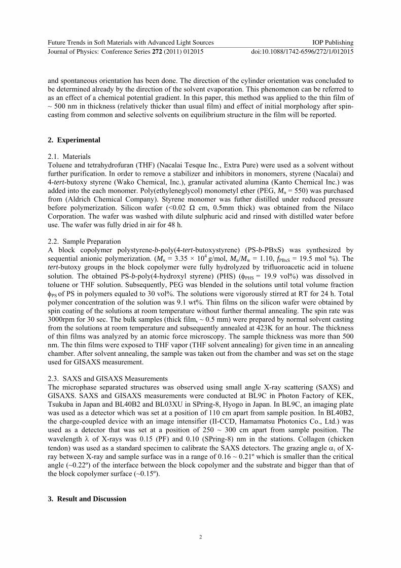
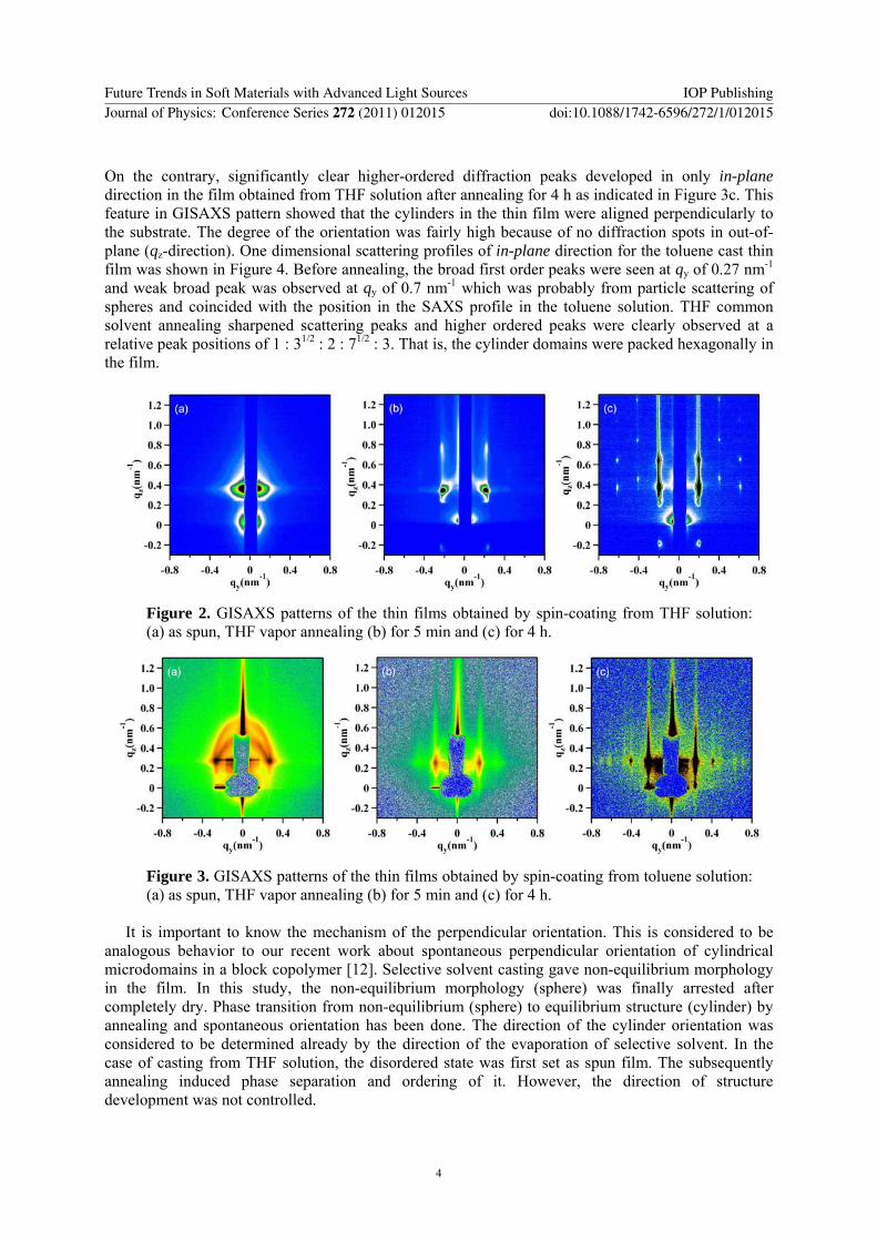
32 Morphology in thin films After spin coating without further thermal annealing GISAXS measurement was conducted to reveal the structure in the thin films As for cast from THF solution there was no significant pattern in Figure 2a that is no clear structure in the film On the other hand longitudinally long elliptic arc pattern appeared in the film made by spin-coated from toluene solution as shown in Figure 3a This pattern was scattering from the microphase-separated spherical structure as appeared in the solution except for lattice disorder After the thin films were exposed to THF vapor (solvent annealing) specific patterns were found for both films In the case of cast from THF solution new scattering spots were clear after annealing for 4 h (Figure 2b) In contrast diffractions of in-plane (qy) direction and vertically long streak-like pattern were observed in the films cast from toluene solution after annealing for only 5 min (Figure 3b) Much long annealing achieved an effect on ordering of the structure for both samples Hexagonal pattern was obtained in the thin film from THF solution after annealing for 24 h (Figure 2c) This pattern was given by the hexagonally arrayed cylinders oriented parallel to the substrate It is common case that the parallel orientation appears in the block copolymer with cylindrical morphology
Future Trends in Soft Materials with Advanced Light Sources IOP PublishingJournal of Physics Conference Series 272 (2011) 012015 doi1010881742-65962721012015
3
On the contrary significantly clear higher-ordered diffraction peaks developed in only in-plane direction in the film obtained from THF solution after annealing for 4 h as indicated in Figure 3c This feature in GISAXS pattern showed that the cylinders in the thin film were aligned perpendicularly to the substrate The degree of the orientation was fairly high because of no diffraction spots in out-of-plane (qz-direction) One dimensional scattering profiles of in-plane direction for the toluene cast thin film was shown in Figure 4 Before annealing the broad first order peaks were seen at qy of 027 nm-1
and weak broad peak was observed at qy of 07 nm-1 which was probably from particle scattering of spheres and coincided with the position in the SAXS profile in the toluene solution THF common solvent annealing sharpened scattering peaks and higher ordered peaks were clearly observed at a relative peak positions of 1 312 2 712 3 That is the cylinder domains were packed hexagonally in the film
Figure 2 GISAXS patterns of the thin films obtained by spin-coating from THF solution (a) as spun THF vapor annealing (b) for 5 min and (c) for 4 h
Figure 3 GISAXS patterns of the thin films obtained by spin-coating from toluene solution (a) as spun THF vapor annealing (b) for 5 min and (c) for 4 h
It is important to know the mechanism of the perpendicular orientation This is considered to be
analogous behavior to our recent work about spontaneous perpendicular orientation of cylindrical microdomains in a block copolymer [12] Selective solvent casting gave non-equilibrium morphology in the film In this study the non-equilibrium morphology (sphere) was finally arrested after completely dry Phase transition from non-equilibrium (sphere) to equilibrium structure (cylinder) by annealing and spontaneous orientation has been done The direction of the cylinder orientation was considered to be determined already by the direction of the evaporation of selective solvent In the case of casting from THF solution the disordered state was first set as spun film The subsequently annealing induced phase separation and ordering of it However the direction of structure development was not controlled
Future Trends in Soft Materials with Advanced Light Sources IOP PublishingJournal of Physics Conference Series 272 (2011) 012015 doi1010881742-65962721012015
4
Figure 4 In-plane 1D-SAXS profiles at qz = ~ 025ordm obtained by spin-coating from toluene solution As-prepared (bottom) THF vapor annealing (middle) for 5 min and (top) for 4 h Thin and thick arrows indicated lattice and form factors respectively
Figure 5 GISAXS profiles of PS-b-PHSPEG thin film obtained by spin-cast from toluene solution The sample was annealed with THF vopar The GISAXS measurement (αi = 018˚) was conducted (a) before and (b) after water washing with exposure (data accumulation) time of X-ray of 250 and 10 ms respectively One-dimensional profiles (red lines right axis) in the Figures indicated in-plane scatterings at qz ~ 035 Finally we tried to remove the blended PEG oligomer from the film with highly perpendicular
oriented cylinders by soaking thin film on the silicon wafer into distilled water The intensity of GISAXS increased by a factor of approximately 20 ~ 30 after washing without any change in peak positions as shown in Figure 5 The perpendicular oriented cylindrical structure was maintained even after washing with water The increase in the GISAXS intensity was ascribed to removing PEG from cylinders and nano-holes were created in the film The generation of nano-holes enhanced the contrast between PS matrix and the cylinders One-dimensional profiles in the Figure (red lines) indicated in-plane scatterings at qz ~ 035 These profiles are slightly different except for peak positions The relative intensity of the higher order peaks to the first order peak increased after removing PEG The change in the intensity ratio is ascribed to the electron-density profile In the thin film a core-shell like cylinder (PHS cylinder including air near the core) can be generated after removing PEG oligomer The values of the electron density ρe for each polymer were calculated to be 0565 for PS and 0629 molcm3 for PHS The PHS chains can be located near the wall of the cylinder and the concentration of
Future Trends in Soft Materials with Advanced Light Sources IOP PublishingJournal of Physics Conference Series 272 (2011) 012015 doi1010881742-65962721012015
5
PHS chains can be imagined to gradually decrease toward the core of the cylinder In this assumption the values of the ρe near the wall of the cylinder and the core of the cylinder are higher and lower than the ρe of PS matrix In such a case intensity of the first order peak diminishes relative to that of the higher order peaks Therefore the nano-hole structure was predicted to be core-shell type cylinder Here let us think the increment of the GISAXS intensity The electron density difference Δρersquo between PS matrix and PHSPEG cylinder as assuming that PHS and PEG fully mix was calculated to be 0051 molcm3 where the ρe for PEG 0594 molcm3 respectively and the volume fraction of PEG in the cylinder is 043 After removing PEG the Δρerdquo between PS matrix and PHSair cylinder was estimated roughly at 025 molcm3 (PHSair domain ρe ~ 0315 molcm3) SAXS intensity is proportional to the square of Δρe The value of (Δρerdquo)2 was 24 times as large as that of (Δρersquo)2 This value is coincidence with the enhancement of GISAXS intensity Additionally we took into consideration the depth of the nano-hole The in-plane profile (not shown) at αi of 014˚ which was lower than the critical angle of the polymer-air interface was almost identical with the profile in Figure 5b Namely there was no significant structural difference between the entire film and the vicinity of the surface This means that the depth of the nano-hole attained the film thickness However more quantitative and accurate calculation are necessity to reveal the more detailed structure in the thin film
Acknowledgment The SAXS and GISAXS measurements were performed at he Photon Factory of High Energy Accelerator Research Organization (Approval 2008G027 2008G525 2010G028) and at SPring-8 (Approval 2009B1103 2010A1180 2010A7225) This research was supported by Ministry of Education Science Sports and Culture Grant-in-Aid for Young Scientists (B) (20750176 2008) Authors thank to Prof Shinichi Sakurai (Kyoto Institute of Technology) Prof Shusaku Nagano (Nagoya University) and Dr Mitsuo Hara (Nagoya University) for their kind help and fruitful discussion
References [1] Lee B Park I Yoon J Park S Kim J Kim K-W Chang T and Ree M 2005 Macromolecules 38
4311 [2] Jin S Yoon J Heo K Park H-W Kim J Kim K-W Shin T J Chang T and Ree M 1997 JAppl
Cryst 40 950 [3] Stein G E Kramer E J Li X and Wang J 2007 Macromolecules 40 2453 [4] Yokoyama H Dutriez C Li L Nemoto T Sugiyama K Sasaki S Masunaga H Takata M and
Okuda H 2007 J Chem Phys 127 014904 [5] Wang J Y Chen W Roy C Sievert J D and Russell T 2008 Macromolecules 41 963 [6] Busch P Posselt D Smilgies D ndashM Rauscher M and Papadakis C M 2007 Macromolecules 40
630 [7] Bang J Kim B J Stein G E Russell T Li X Wang J Kramer E J and Hawker C J 2007
Macromolecules 40 7019 [8] Xu T Goldbach J T Misner M J Kim S Gibaud A Gang O Ocko B Guarini K W Black C T
Hawker C J and Russell T 2004 Macromolecules 37 2972 [9] Cavicchi K and Russell T 2007 Macromolecules 40 1181 [10] Potemkin I I 2004 Macromolecules 37 3505 [11] Horvat A Knoll A Krausch G Tsarkova L Lykhova K S Sevink G J A Zvelindovsky A V
and Magerle R 2007 Macromolecules 40 6930 [12] Sakurai S Bando H Yoshida H Fukuoka R Mouri M Yamamoto K and Okamoto S 2009
Macromolecules 42 2115 [13] Hashimoto T Kawamura T Harada M and Tanaka H 1994 Macromolecules 27 3063 [14] Bosch P Rauscher M Smilgies D-M Posselt D Papadakis C M 2006 J Appl Crystallogr 39
433
Future Trends in Soft Materials with Advanced Light Sources IOP PublishingJournal of Physics Conference Series 272 (2011) 012015 doi1010881742-65962721012015
6

Solvent Annealing Induced Perpendicular Orientation of Cylindrical Microdomains in Polystyrene-b-poly(4-hydroxyl styrene)PEG Oligomer Blend Thin Film Made by Spin-coating from Selective Solvent
Taito Matsutani and Katsuhiro Yamamoto
Department of Materials Science amp Technology Graduate School of Engineering Nagoya Institute of Technology Gokiso-cho Showa-ku Nagoya 466-8555 Japan
yamamotokatsuhironitechacjp
Abstract The microphase separated structure of PS-b-PHSPEG blend thin film with thickness of 500 ~ 600 nm was investigated by grazing incidence small angle X-ray scattering The thin film was obtained by two different solutions one was THF which was common good solvent for all components of polymers used here The other is toluene which was selective solvent for PS and poor-solvent for PHS and PEG The equilibrium morphology of the block copolymer and blend sample was hexagonally packed cylinder in the bulk and thin film The structure in the thin film obtained by spin cast from toluene solution was non-equilibrium After THF vopar annealing of the thin film (cast from toluene) the highly ordered and perpendicular oriented cylindrical structure was obtained Perpendicular orientation was failure when the thin film sample made by spin cast from THF solution and subsequent THF vapor annealing The perpendicular nano-holes were fabricated after removing PEG oligomer by washing with water
1 Introduction Microphase separated structures of block copolymer thin films were extensively investigated by grazing incidence small angle X-ray scattering technique (GISAXS)[1-6] Controlling the morphology and particularly the orientation behaviour of phase-separated structures in both thin and thick films has received considerable attention because of their potential nanofabrication application In the thin film surface-polymer interaction confinement effect and the film thickness are really important factor to give a morphology that is different from those in the bulk Some researchers have achieved perpendicular orientation of cylindrical morphology of block copolymer in thin film by controlling above factors The study on orientation of microphase separated structure has been reported extensively Solvent annealing [7-9] ion doping [5] surface modification of substrate (controlling interfacial energy) and thickness controlling related to the commensurability of domain spacing with film thickness [1011] are effective ways to orient the microphase separated structures In a thicker film we reported spontaneous perpendicular orientation of cylindrical microdomains in a block copolymer normal cast film [12] Selective solvent casting gave nonequilibrium morphology because one block fully shrank Since vitrification of the shrunk chains occurred during evaporation of the solvent the nonequilibrium morphology was finally arrested after completely dry Appropriate annealing induced phase transition from nonequilibrium (sphere) to equilibrium structure (cylinder)
Future Trends in Soft Materials with Advanced Light Sources IOP PublishingJournal of Physics Conference Series 272 (2011) 012015 doi1010881742-65962721012015
Published under licence by IOP Publishing Ltd 1
and spontaneous orientation has been done The direction of the cylinder orientation was concluded to be determined already by the direction of the solvent evaporation This phenomenon can be referred to as an effect of a chemical potential gradient In this paper this method was applied to the thin film of ~ 500 nm in thickness (relatively thicker than usual film) and effect of initial morphology after spin-casting from common and selective solvents on equilibrium structure in the film will be reported
2 Experimental
21 Materials Toluene and tetrahydrofuran (THF) (Nacalai Tesque Inc Extra Pure) were used as a solvent without further purification In order to remove a stabilizer and inhibitors in monomers styrene (Nacalai) and 4-tert-butoxy styrene (Wako Chemical Inc) granular activated alumina (Kanto Chemical Inc) was added into the each monomer Poly(ethyleneglycol) monometyl ether (PEG Mn = 550) was purchased from (Aldrich Chemical Company) Styrene monomer was futher distilled under reduced pressure before polymerization Silicon wafer (lt002 Ω cm 05mm thick) was obtained from the Nilaco Corporation The wafer was washed with dilute sulphuric acid and rinsed with distilled water before use The wafer was fully dried in air for 48 h
22 Sample Preparation A block copolymer polystyrene-b-poly(4-tert-butoxystyrene) (PS-b-PBxS) was synthesized by sequential anionic polymerization (Mn = 335 times 104 gmol MnMw = 110 fPBxS = 195 mol ) The tert-butoxy groups in the block copolymer were fully hydrolyzed by trifluoroacetic acid in toluene solution The obtained PS-b-poly(4-hydroxyl styrene) (PHS) (φPHS = 199 vol) was dissolved in toluene or THF solution Subsequently PEG was blended in the solutions until total volume fraction φPS of PS in polymers equaled to 30 vol The solutions were vigorously stirred at RT for 24 h Total polymer concentration of the solution was 91 wt Thin films on the silicon wafer were obtained by spin coating of the solutions at room temperature without further thermal annealing The spin rate was 3000rpm for 30 sec The bulk samples (thick film ~ 05 mm) were prepared by normal solvent casting from the solutions at room temperature and subsequently annealed at 423K for an hour The thickness of thin films was analyzed by an atomic force microscopy The sample thickness was more than 500 nm The thin films were exposed to THF vapor (THF solvent annealing) for given time in an annealing chamber After solvent annealing the sample was taken out from the chamber and was set on the stage used for GISAXS measurement
23 SAXS and GISAXS Measurements The microphase separated structures was observed using small angle X-ray scattering (SAXS) and GISAXS SAXS and GISAXS measurements were conducted at BL9C in Photon Factory of KEK Tsukuba in Japan and BL40B2 and BL03XU in SPring-8 Hyogo in Japan In BL9C an imaging plate was used as a detector which was set at a position of 110 cm apart from sample position In BL40B2 the charge-coupled device with an image intensifier (II-CCD Hamamatsu Photonics Co Ltd) was used as a detector that was set at a position of 250 ~ 300 cm apart from sample position The wavelength λ of X-rays was 015 (PF) and 010 (SPring-8) nm in the stations Collagen (chicken tendon) was used as a standard specimen to calibrate the SAXS detectors The grazing angle αi of X-ray between X-ray and sample surface was in a range of 016 ~ 021ordm which is smaller than the critical angle (~022ordm) of the interface between the block copolymer and the substrate and bigger than that of the block copolymer surface (~015ordm)
3 Result and Discussion
Future Trends in Soft Materials with Advanced Light Sources IOP PublishingJournal of Physics Conference Series 272 (2011) 012015 doi1010881742-65962721012015
2
31 Morphology in bulk and solutions The morphology of the synthesized PS-b-PHS and PS-b-PHSPEG Blend was hexagonally packed cylindrical structure as shown in Figure 1a These films were obtained after casting from THF solution and subsequently annealing at 423K Even if PEG oligomer was added in the sample the cylindrical morphology was maintained except for domain spacing The domain spacing increased due to swelling of PHS cylinder domains by incorporation of PEG into them How about the morphology in the solutions THF is a common good solvent for all of components Toluene is good solvent for PS but poor solvent for PHS and PEG In a common solution (THF) no structure was observed at a concentration of 10wt as shown in Figure 1b The common solvent diluted segregation power χN by factor φS (χ is the Flory-Huggins interaction parametner N is the total number of degree of polymerization φS is the solution concentration) A decrease in the φSχN put the system into disordered phase On the other hand in a selective solvent (toluene) the segregation power expected to be increased and the chains of PHS and PEG shrunk in toluene solution These situations gave the much different morphology in comparison with that in THF solution Figure 1b shows the microphase separated structure which was not completely assigned but probably spherical morphology in toluene The thin films were obtained by spin-coating from these solutions
Figure 1 SAXS profiles of (a) PS-b-PHS and PS-b-PHSPEG blend bulk films and (b) PS-b-PHSPEG in THF (upper) and toluene (bottom) solutions Thin and thick arrows indicated lattice and form factors respectively
32 Morphology in thin films After spin coating without further thermal annealing GISAXS measurement was conducted to reveal the structure in the thin films As for cast from THF solution there was no significant pattern in Figure 2a that is no clear structure in the film On the other hand longitudinally long elliptic arc pattern appeared in the film made by spin-coated from toluene solution as shown in Figure 3a This pattern was scattering from the microphase-separated spherical structure as appeared in the solution except for lattice disorder After the thin films were exposed to THF vapor (solvent annealing) specific patterns were found for both films In the case of cast from THF solution new scattering spots were clear after annealing for 4 h (Figure 2b) In contrast diffractions of in-plane (qy) direction and vertically long streak-like pattern were observed in the films cast from toluene solution after annealing for only 5 min (Figure 3b) Much long annealing achieved an effect on ordering of the structure for both samples Hexagonal pattern was obtained in the thin film from THF solution after annealing for 24 h (Figure 2c) This pattern was given by the hexagonally arrayed cylinders oriented parallel to the substrate It is common case that the parallel orientation appears in the block copolymer with cylindrical morphology
Future Trends in Soft Materials with Advanced Light Sources IOP PublishingJournal of Physics Conference Series 272 (2011) 012015 doi1010881742-65962721012015
3
On the contrary significantly clear higher-ordered diffraction peaks developed in only in-plane direction in the film obtained from THF solution after annealing for 4 h as indicated in Figure 3c This feature in GISAXS pattern showed that the cylinders in the thin film were aligned perpendicularly to the substrate The degree of the orientation was fairly high because of no diffraction spots in out-of-plane (qz-direction) One dimensional scattering profiles of in-plane direction for the toluene cast thin film was shown in Figure 4 Before annealing the broad first order peaks were seen at qy of 027 nm-1
and weak broad peak was observed at qy of 07 nm-1 which was probably from particle scattering of spheres and coincided with the position in the SAXS profile in the toluene solution THF common solvent annealing sharpened scattering peaks and higher ordered peaks were clearly observed at a relative peak positions of 1 312 2 712 3 That is the cylinder domains were packed hexagonally in the film
Figure 2 GISAXS patterns of the thin films obtained by spin-coating from THF solution (a) as spun THF vapor annealing (b) for 5 min and (c) for 4 h
Figure 3 GISAXS patterns of the thin films obtained by spin-coating from toluene solution (a) as spun THF vapor annealing (b) for 5 min and (c) for 4 h
It is important to know the mechanism of the perpendicular orientation This is considered to be
analogous behavior to our recent work about spontaneous perpendicular orientation of cylindrical microdomains in a block copolymer [12] Selective solvent casting gave non-equilibrium morphology in the film In this study the non-equilibrium morphology (sphere) was finally arrested after completely dry Phase transition from non-equilibrium (sphere) to equilibrium structure (cylinder) by annealing and spontaneous orientation has been done The direction of the cylinder orientation was considered to be determined already by the direction of the evaporation of selective solvent In the case of casting from THF solution the disordered state was first set as spun film The subsequently annealing induced phase separation and ordering of it However the direction of structure development was not controlled
Future Trends in Soft Materials with Advanced Light Sources IOP PublishingJournal of Physics Conference Series 272 (2011) 012015 doi1010881742-65962721012015
4
Figure 4 In-plane 1D-SAXS profiles at qz = ~ 025ordm obtained by spin-coating from toluene solution As-prepared (bottom) THF vapor annealing (middle) for 5 min and (top) for 4 h Thin and thick arrows indicated lattice and form factors respectively
Figure 5 GISAXS profiles of PS-b-PHSPEG thin film obtained by spin-cast from toluene solution The sample was annealed with THF vopar The GISAXS measurement (αi = 018˚) was conducted (a) before and (b) after water washing with exposure (data accumulation) time of X-ray of 250 and 10 ms respectively One-dimensional profiles (red lines right axis) in the Figures indicated in-plane scatterings at qz ~ 035 Finally we tried to remove the blended PEG oligomer from the film with highly perpendicular
oriented cylinders by soaking thin film on the silicon wafer into distilled water The intensity of GISAXS increased by a factor of approximately 20 ~ 30 after washing without any change in peak positions as shown in Figure 5 The perpendicular oriented cylindrical structure was maintained even after washing with water The increase in the GISAXS intensity was ascribed to removing PEG from cylinders and nano-holes were created in the film The generation of nano-holes enhanced the contrast between PS matrix and the cylinders One-dimensional profiles in the Figure (red lines) indicated in-plane scatterings at qz ~ 035 These profiles are slightly different except for peak positions The relative intensity of the higher order peaks to the first order peak increased after removing PEG The change in the intensity ratio is ascribed to the electron-density profile In the thin film a core-shell like cylinder (PHS cylinder including air near the core) can be generated after removing PEG oligomer The values of the electron density ρe for each polymer were calculated to be 0565 for PS and 0629 molcm3 for PHS The PHS chains can be located near the wall of the cylinder and the concentration of
Future Trends in Soft Materials with Advanced Light Sources IOP PublishingJournal of Physics Conference Series 272 (2011) 012015 doi1010881742-65962721012015
5
PHS chains can be imagined to gradually decrease toward the core of the cylinder In this assumption the values of the ρe near the wall of the cylinder and the core of the cylinder are higher and lower than the ρe of PS matrix In such a case intensity of the first order peak diminishes relative to that of the higher order peaks Therefore the nano-hole structure was predicted to be core-shell type cylinder Here let us think the increment of the GISAXS intensity The electron density difference Δρersquo between PS matrix and PHSPEG cylinder as assuming that PHS and PEG fully mix was calculated to be 0051 molcm3 where the ρe for PEG 0594 molcm3 respectively and the volume fraction of PEG in the cylinder is 043 After removing PEG the Δρerdquo between PS matrix and PHSair cylinder was estimated roughly at 025 molcm3 (PHSair domain ρe ~ 0315 molcm3) SAXS intensity is proportional to the square of Δρe The value of (Δρerdquo)2 was 24 times as large as that of (Δρersquo)2 This value is coincidence with the enhancement of GISAXS intensity Additionally we took into consideration the depth of the nano-hole The in-plane profile (not shown) at αi of 014˚ which was lower than the critical angle of the polymer-air interface was almost identical with the profile in Figure 5b Namely there was no significant structural difference between the entire film and the vicinity of the surface This means that the depth of the nano-hole attained the film thickness However more quantitative and accurate calculation are necessity to reveal the more detailed structure in the thin film
Acknowledgment The SAXS and GISAXS measurements were performed at he Photon Factory of High Energy Accelerator Research Organization (Approval 2008G027 2008G525 2010G028) and at SPring-8 (Approval 2009B1103 2010A1180 2010A7225) This research was supported by Ministry of Education Science Sports and Culture Grant-in-Aid for Young Scientists (B) (20750176 2008) Authors thank to Prof Shinichi Sakurai (Kyoto Institute of Technology) Prof Shusaku Nagano (Nagoya University) and Dr Mitsuo Hara (Nagoya University) for their kind help and fruitful discussion
References [1] Lee B Park I Yoon J Park S Kim J Kim K-W Chang T and Ree M 2005 Macromolecules 38
4311 [2] Jin S Yoon J Heo K Park H-W Kim J Kim K-W Shin T J Chang T and Ree M 1997 JAppl
Cryst 40 950 [3] Stein G E Kramer E J Li X and Wang J 2007 Macromolecules 40 2453 [4] Yokoyama H Dutriez C Li L Nemoto T Sugiyama K Sasaki S Masunaga H Takata M and
Okuda H 2007 J Chem Phys 127 014904 [5] Wang J Y Chen W Roy C Sievert J D and Russell T 2008 Macromolecules 41 963 [6] Busch P Posselt D Smilgies D ndashM Rauscher M and Papadakis C M 2007 Macromolecules 40
630 [7] Bang J Kim B J Stein G E Russell T Li X Wang J Kramer E J and Hawker C J 2007
Macromolecules 40 7019 [8] Xu T Goldbach J T Misner M J Kim S Gibaud A Gang O Ocko B Guarini K W Black C T
Hawker C J and Russell T 2004 Macromolecules 37 2972 [9] Cavicchi K and Russell T 2007 Macromolecules 40 1181 [10] Potemkin I I 2004 Macromolecules 37 3505 [11] Horvat A Knoll A Krausch G Tsarkova L Lykhova K S Sevink G J A Zvelindovsky A V
and Magerle R 2007 Macromolecules 40 6930 [12] Sakurai S Bando H Yoshida H Fukuoka R Mouri M Yamamoto K and Okamoto S 2009
Macromolecules 42 2115 [13] Hashimoto T Kawamura T Harada M and Tanaka H 1994 Macromolecules 27 3063 [14] Bosch P Rauscher M Smilgies D-M Posselt D Papadakis C M 2006 J Appl Crystallogr 39
433
Future Trends in Soft Materials with Advanced Light Sources IOP PublishingJournal of Physics Conference Series 272 (2011) 012015 doi1010881742-65962721012015
6