set-rlement/water issues related to placement of
TRANSCRIPT

SET-rLEMENT/WATER ISSUES RELATED TO PLACEMENT OF ADDITIONALMATERIAL ON THE EXISTING TAILINGS IMPOUNDMENT
NORTHEAST CHURCHROCK MINE
GALLUP, NM
PREPARED FOR:
UNITED NUCLEAR CORPORATION
an indirect subsidiary of
GENERAL ELECTRIC COMPANY
640 Freedom Business Center
King of Prussia, PA 19406
On behalf of UNITED NUCLEAR CORPORATION
PREPARED BY:
STEPHEN F. DWYER, PHD, PE
DWYER ENGINEERING, LLC
1813 STAGECOACH RD. SE
ALBUQUERQUE, NM 87123
FEBRUARY 2010

DWYER ENGINEERING, LLC
TABLE OF CONTENTS Page
EXECUTIVE SUMMARY 3
1.0 INTRODUCTION 3
2.0 SETTLEMENT 4
3.0 MODELING 6
3.1 OVERVIEW OF UNSATH 7
3.2 INPUT PARAMETERS 8
3.2.1 MODEL GEOMETRY 8
3.2.2 BOUNDARY CONDITIONS 8
3.2.3 VEGETATION DATA 9
3.2.4 SOIL PROPERTIES RELATED TO VEGETATION 10
3.2.5 SOIL PROPERTIES 10
3.3 MODELING RESULTS 12
4.0 DISCUSSION 13
5.0 REFERENCES 16
FIGURES
Figure 1. Profile of Existing Tailings Impoundment 5
Figure 2. USDA Soil Classification 11
Figure 3. Model Results - Initial and Final Soil Suction Values 13
Figure 4. Moisture States of Soil 15
TABLES
Table 1. SOIL HYDRAULIC PROPERTIES 12
2

DWYER ENGINEER[NG, LLC
EXECUTIVE SUMMARYThis report provides a preliminary evaluation of potential settlement issues associatedwith the placement of soils removed during the Northeast Church Rock Mine SiteRemoval Action directly on parts or all of the existing tailings impoundments at theadjacent Northeast Church Rock Mill Site. Specifically, the question was raised whetherthere is a possibility that significant water could be 'squeezed' from the existing finegrained tailings due to additional surcharge loading on the tailings impoundment. Theoriginal fine tailings were placed in a near saturated state and were covered about twodecades ago.
Findings from this cursory evaluation conclude that water will not be 'squeezed' from theexisting fine grained tailings due to the proposed surcharge loads. The evaluation isbased on available data from existing documentation of the tailings closure, estimatedvalues, and values from the literature.
1.0 INTRODUCTION
The Northeast Church Rock (NECR) Mine Site was an underground Uranium mineactive from 1968 to 1982, when it went to stand-by status. The primary ore mined wascoffinite. Mine reclamation is warranted as a result of these mining operations.
An Engineering Evaluation/Cost Analysis (EE/CA) was prepared by the United StatesEnvironmental Protection Agency (EPA), Region 9 to evaluate Non-Time- CriticalRemoval Action (NTCRA or "Removal Action") alternatives for soil and sediment (minewastes) at NECR. The site is located about 16 miles northeast of Gallup in McKinleyCounty, New Mexico. The site is a semi-arid climate averaging about 12-inches ofprecipitation per year at an elevation of about 7000-ft above sea level. The vegetationis generally categorized as a pinyon-juniper landscape with shrubs and native grasses.The near surface soil and alluvium on site are predominantly a clay loam.
The primary elements of the Preferred Alternative from the EECA include:
" Excavation and transport of all mine waste soil with radium above 2.24 pCi/g (10-4), except in the ponds, where it would be excavated to a maximum depth of 10feet. - Consolidation of the mine wastes with a cap and liner in an existingdisposal cell on the adjacent UNC mill site, or construction of a new cell at theUNC mill facility currently under license by the U.S. Nuclear RegulatoryCommission (NRC);
" Principal threat mine wastes to be taken to an off-site licensed controlleddisposal facility, such as at Grandview, ID, or an alternative appropriate facility.For waste with total Uranium concentrations exceeding 500 mg/kg, it may beviable to reprocess the waste at the White Mesa Mill in Utah or a similar mill;
" Site restoration with erosion and storm water controls, regrading andrevegetation for future grazing; and
3

DWYER ENGINEERING, LLC
* Long-term maintenance for capped repository, which would occupy an estimated30 acres and would become part of DOE's legacy management program inperpetuity.
United Nuclear is evaluating the possibility of placing soils removed during the RemovalAction on one or more of the existing tailings impoundments rather than creating a newrepository on-site. This evaluation examines the possibility of settlement of the existingburied tailings and the subsequent potential 'squeezing' of additional water from thesefine grained tailings.
2.0 SETTLEMENT
The following profile was used to evaluate settlement in the fine grained tailings layer(figure 1). The assumed worst case profile was evaluated whereby the fine grainedtailings were approximately 15-ft thick while the coarse tailings were only 7-ft thick. The7-ft thick coarse tailings is the minimum thickness for this layer and thus offered thelowest pressure on the fine-grained tailings and thus the minimum amount of primaryconsolidation from the original closure.
4

DWYER ENGINEERING, LLC
c-s~ana
274NOWt
-P01)24
A&Whm
FIGURE 1PROFILE OF EXISTING TAILINGS IMPOUNDMENT
Terzaghi's theory of consolidation was utilized to calculate the primary settlement in thefine grained tailings from this original profile. The following assumptions were utilized:
1.2.3.
Terzaghi's 1 -D consolidation theory is valid for this case;The fine grained tailings behave as a saturated clay;Soil parameters from various 'as-built' reports from the tailings closure andassumed values where soil parameters in prior reports were not found.
Sc = Cc * [H/(1 + eo)] * log [(a .+ Aa)/o-]
Sc = Ca * Ho* log [t2/tj)
primary consolidation
secondary consolidation
5

DWYER ENGINEERING,ý LLC
Refer to Appendix A for more details of calculations. A summary of the calculationsinclude:
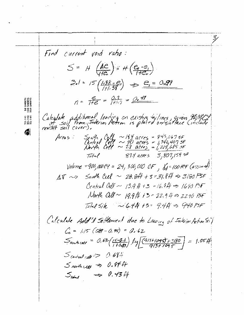
* Primary consolidation in fine grained tailings layer is 2-ft. The time-dependentsecondary consolidation in the same layer is 1.1 ft. The total settlement to datein the fine grained tailings layer is approximately 3.1-ft.
* It is undetermined whether the best scenario would include placing all of the soilremoved from the interim action (about 900,000 CY) on the south, central, ornorth cell; or spreading it over all three cells. Consequently an analysis wasperformed to evaluate all 4 scenarios. The original void ratio in the fine grainedtailings layer was assumed to be 1.38 based on the applicable references.Assuming the total soil removed from the interim action were placed on thesouth, central, or north cell; or spreading it over all three cells; the new void ratio(e) and porosity (n) for this fine grained tailings layer as a result of the totalsettlement discussed above is:o Scenario 1 - Interim soil placed on South Cell: e = 0.72; n = 0.42;o Scenario 2 - Interim soil placed on Central Cell: e = 0.78; n = 0.44;o Scenario 3 - Interim soil placed on North Cell: e = 0.76; n = 0.43;o Scenario 4 - Interim soil placed on Total of all Cells = 0.82; n = 0.45.
The maximum water content a soil can hold after all downward drainage resulting fromgravitational forces is referred to as its field capacity. Field capacity is often arbitrarilyreported as the water content at 330-cm of matric potential head (Jury et al. 1991).Below field capacity, the hydraulic conductivity is assumed to be so low that gravitydrainage becomes negligible and the soil moisture is held in place by suction or matricpotential. Consequently, a soil's field capacity is deemed to bound the soil layermoisture content or have excess pore water pressure to yield significant moisture fromthe proposed 'squeezing' water out of the fine grained soil layer scenarios discussedabove.
3.0 MODELING
The profile (figure 1) was modeled to evaluate the condition of the fine grained tailingslayer after the primary and secondary settlement occurred (3.1-ft), but prior toplacement of additional soil from the interim action was placed on a tailings cell. Theprofile was modeled to evaluate the unsaturated flow over the 19 years from theassumed end of the primary consolidation until the current date. The initial condition ofthe fine grained soil was assumed to be at field capacity following the primaryconsolidation. This is a conservative assumption because during primary consolidation,the excess pore water is squeezed from the soil pore spaces. Thus the wettestcondition it can be in following primary consolidation is the moisture content associatedwith the field capacity of the soil. It is conservative because it is likely the soil is drierthan the moisture content associated with the field capacity. The resulting condition ofthe fine grained tailings layer could then be compared to the field capacity of thecalculated moisture characteristic curves for each scenario evaluated after the 19 year
6

DWYER ENGINEERING, LLC
period. If the condition of the fine grained tailings layer had a soil suction greater thanits respective field capacity, then it is determined that any water remaining in the layer iswithin the water storage capacity of that layer and thus no water will be squeezed out. Ifthe suction is less than the field capacity, then excess water can be squeezed out.
Software [UNSAT H (Fayer 2000)] utilized for the analysis of the unsaturated analysis isbased on the Richard's Equation (ITRC 2003). The Richards Equation is as follows:
oK •'A(z,t)at 8- 8Z
Where:
K is the hydraulic conductivity,
kV is the pressure head,
z is the elevation above a vertical datum,
0 is the water content,
t is time, and
A(z,) = a sink term for root water uptake.
The cover profile modeled utilized an upper boundary condition composed of site-specific average climate data for a period of 19 years.
3.1 OVERVIEW OF UNSAT-H
UNSAT-H is a one-dimensional, finite-difference computer program developed at thePacific Northwest National Laboratory by Fayer and Jones (1990). UNSAT-H simulateswater flow through soils by solving Richards' Equation and simulates heat flow bysolving Fouriers heat conduction equation.
UNSAT-H separates precipitation falling on an earthen cover into infiltration andoverland flow. The quantity of water that infiltrates depends on the infiltration capacity ofthe soil profile immediately prior to rainfall (e.g., total available porosity). Thus, thefraction of precipitation shed as overland flow depends on the saturated andunsaturated hydraulic conductivities of the soil included in the final cover. If the rate ofprecipitation exceeds the soil's infiltration capacity, the excess water is shed as surfacerunoff. UNSAT-H does not consider absorption and interception of water by the plantcanopy or the effect of slope and slope-length when computing surface runoff since it isa 1-dimensional model.
Water that has infiltrated a soil profile during an UNSAT-H simulation moves upward ordownward as a consequence of gravity and matric potential. Evaporation from thecover surface is computed using Fick's law. Water removal by transpiration of plants is
7

DWYER ENGINEERING, LLC
treated as a sink term in Richards' equation. Potential evapotranspiration (PET) iscomputed from the daily wind speed, relative humidity, net solar radiation, and dailyminimum and maximum air temperatures using a modified form of Penman's equationgiven by Doorenbos and Pruitt (1977). Soil water storage is computed by integratingthe water content profile. Flux from the lower boundary is via percolation. UNSAT-H,being a one-dimensional program, does not compute lateral drainage.
3.2 INPUT PARAMETERS
A set of input parameters were developed for simulations using UNSAT-H for the soilprofile. These parameters were developed based on field and laboratorymeasurements, values from the literature, and assumed values.
3.2.1 MODEL GEOMETRY
The model geometry is that shown in Figure 1.
3.2.2 BOUNDARY CONDITIONS
Weather data available through the United States Department of Commerce, NationalClimate Data Center was evaluated(http://cdo.ncdc.noaag.qov/ops/Dpclimprod/poemain.accessrouter?datasetabbv=SOD&countryabbv=&qeoreqionabbv=). An average climate year (1949) consisting of an annualprecipitation of 11.7 inches (29.7 cm) of precipitation was utilized for 19 consecutiveyears. The PET during this period was calculated via New Mexico State University'sPotential and Actual Crop Evapotranspiration Wizard. This software package availableon the internet at http://weather.nmsu.edu/pet/JS pet.htm was utilized to calculate dailyPET values based on the daily weather data. The maximum and minimum dailytemperatures, daily precipitation value, site latitude, and a site specific calibrationcoefficient of 0.16 were input parameters used to calculate PET (Samani and Pessarkli,1986). The Samani method used to calculate PET correlates very well with the Penmanmethod utilized within UNSAT H (Samani and Pessarkli, 1986).
The flow of water across the surface and lower boundary of the cover profile of interestis determined by boundary condition specifications. For infiltration events, the upperboundary was set to a maximum hourly flux (representative of local conditions). Forthese runs it was conservatively set to 0.4 inches (1 cm) per hour that produced minimalrunoff while maximizing infiltration. The UNSAT-H program partitions PET into potentialevaporation (Ep) and potential transpiration (Tp). Potential evaporation is estimated orderived from daily weather parameters (Fayer 2000). Potential transpiration iscalculated using a function (Equation 1) that is based on the value of the assigned leafarea index (LAI) and an equation developed by Ritchie and Burnett (1971) as follows:
Tp = PET [a + b(LAI)c] where d < LAI !5 e Equation 1
where:
a,b,c,d, and e are fitting parameters;
8

DWYER ENGINEERING, LLC
. a = 0.0, b = 0.52, and c = 0.5, d = 0.1, and e = 2.7 (Fayer 2000)
The UNSAT-H program then partitioned the daily PET values into Ep and Tp. Tp wascalculated using a function developed by Equation 1 above.
The lower boundary condition used was set as a unit gradient. This boundary conditionwas placed deep in the soil profile modeled; well beneath the fine grained tailings layerand any transient moisture activity to ensure it had no significant impact on thepredicted outcome.
3.2.3 VEGETATION DATA
The input parameters representing vegetation include the LAI, rooting depth anddensity, root growth rate, the suction head values that corresponds to the soil's fieldcapacity, wilting point, and water content above which plants do not transpire becauseof anaerobic conditions. The onset and termination of the growing season for the siteare defined in terms of Julian days. A percent bare area is also defined in the UNSAT Hmodel and is often based on visual observation of undisturbed areas near theevaporation ponds. The maximum rooting depth should be based on expected.vegetation characteristics. The root length density (RLD) in UNSAT H is assumed tofollow an exponential function such as that defined in Equation 2:
RLD = a exp(-bz) + c Equation 2
where:
a,b, and c are fitting parameters
z = depth below surface
The parameters used for the RLD functions in Equation 2 were:.a = 0.315, b=0.0073,and c = 0.076 (Fayer 2000). The time required for maximum rooting depthestablishment was set at full depth beginning on day 1. The rooting depth wasconservatively set at 2-feet (60 cm) based on field observations. This is veryconservative given roots from native shrubs and grasses can easily reach depths muchgreater than this.
An average LAI of 1.8 was used (Dwyer 2003). The onset and termination of thegrowing season for the site were Julian days 75 and 299, respectively. The LAI wastransitioned from 0 to 1.8 starting with Julian day 75 to 135. Day 135 through 250, thefull LAI equal to 1.8 was utilized. The LAI was then transitioned down from 1.8 to 0 fromJulian day 250 to 299. This was conservative since it is realistic that plants cantranspire year round at this site. An average percent bare area of 75% was used in theUNSAT H model based on visual observation of native vegetation in the surroundingarea. This is conservative given many areas have higher plant densities than theassumed 25% coverage and an effective ET Cover should produce vegetation as goodas or better than the surrounding areas due to seeding operations and lack of a shallow
9

DWYER ENGINEERING, LLC
caliche layer that limits the storage capacity. Furthermore, the assumed percent barearea of 75% essentially reduces the maximum LAI to 0.45 (25% of 1.8).
3.2.4 SOIL PROPERTIES RELATED TO VEGETATION
Suction head values corresponding to the wilting point, field capacity, and a head valuecorresponding to the water content above which plants do not transpire because ofanaerobic conditions were defined. Matric potential or suction heads are generallywritten as positive numbers, but in reality are negative values. Consequently, the higherthe value, the greater the soil suction. The maximum water content a soil can hold afterall downward drainage resulting from gravitational forces is referred to as its fieldcapacity. Field capacity is arbitrarily reported as the water content at about 10.8 ft (330-cm) of matric potential head (Jury et al. 1991). Below field capacity, the hydraulicconductivity is assumed to be so low that gravity drainage becomes negligible and thesoil moisture is held in place by suction or matric potential.
Not all of the water stored in the soil can be removed via transpiration. Vegetation isgenerally assumed to reduce the soil moisture content to the permanent wilting point,which is typically defined as the water content at 656.2 ft (20,000 cm) of matric potentialhead for native grasses. This 656.2 ft (20,000 cm) value was conservatively usedalthough some shrubs present in the area could remove water from the soil to a suctionof 3280.8 ft (100,000 cm) (Hillel 1998). Evaporation from the soil surface can furtherreduce the soil moisture below the wilting point toward the residual saturation, which isthe water content at an infinite matric potential. The head corresponding to the watercontent below which plant transpiration starts to decrease was defined as 32.2 ft (1000cm) (Fayer 2000). The head value corresponding to the water content above whichplants do not transpire because of anaerobic conditions was defined at 4-in (10 cm)based on the assumed moisture characteristic curves for the utilized soil hydraulicproperties.
3.2.5 SOIL PROPERTIES
Soil hydraulic properties were based on grain size distributions of soil samplessummarized in AMEC (2008) for alluvium material and "as-built" reports for tailingsmaterial. This data was then used to classify the soil according to the United StatesDepartment of Agriculture (USDA) soil classification system (Table 1 and Figure 2).Data from the RETC model was then utilized for the classified soils to determine theirunsaturated and saturated hydraulic properties. The RETC Model was developed bythe US Salinity Laboratory for quantifying the hydraulic functions of unsaturated soils
10
I

DWYER ENGINEERING, LLC
Soil Texture Triangle
Q%1OO
1Q
0
Percent Sand
Figure 2. USDA Soil ClassificationSand: Soil particles between 0.05 and 2.0 mm in sizeSilt: Soil particles between 0.002 mm and 0.05 mm
Clay: Soil particles smaller than 0.002 mm (2 microns) in size
The Mualem (van Genuchten et al 1991) conductivity function was used to describe theunsaturated hydraulic conductivity of the soils. The van Genuchten 'm' parameter forthis function is assumed to be'l-1/n'; 'n' being one of the established van Genuchtenparameters (van Genuchten et al 1991). The initial suction value for soil layers otherthan the fine grained tailings layer modeled were set at a value of 10,000 cm. The initialsuction value for the fine grained soil was set at its field capacity or 330 cm. This valuefor the fine grained tailings layer was utilized because it is assumed that following theprimary consolidation of this layer, the soil suction of this soil layer would be no lessthan this value. During primary consolidation a soil's excess. pore water is squeezed outyielding a layer that is at least as dry as its moisture content related to field capacity ordrier.
The following are the soil properties utilized in the modeling performed.
I1

DWYER ENGINEERING, LLC
Table ISOIL HYDRAULIC PROPERTIES
1,•r pthi:VanGenucte'iiaranieter . .
0 Ikeference~BGS 1,0 (cm/lhr), 03, nr~1cr)
Rock/SoilSurface 0 to 6-in 3.64 0o43 0.06 0.1057 1.36 Dwyer 2003
Layer
Cover Soil 6-in to 2- 0.23 039 0.075 0",039 1.194 RETC Model forft Clay; Loam
Coarse RETC Model forTailings 2-ft to 9- 4.42 0.44 0.065 0.075 1.89 Sandy Loam with
ft 0 modified en perreported porosity,
Fine, RETC Model forTailings 9-ft to 0.2 0.47 0.068 0.008 1.09 Clay with modified
24-ft P, per reportedporosity
Alluvium 24-ft to 0.23 0.39 0.075 0039 1.194 RETC:Modelfor54-ft' Clay L.oam
BGS = below ground surface
3.3 MODELING RESULTS
The modified soil properties based on the primary and secondary settlement weremodeled with the results summarized in figure 2. The water storage capacity of thevarious soil layers is bounded by the suction associated with field capacity (330 cm) andthe wilting point (15,000 cm). Initial suction values at the end of the primary settlementare shown as are the final suction values at the completion of the 19 year period wheresecondary settlement was ongoing. The final suction values are those assumed topresent if soils excavated during the Removal Action were placed directly on the tailingscells.
It can be seen from the final suction values in Figure 2 that the soils in the fine grainedlayer have dried significantly resulting in elevated suction values. Because the suctionvalues are significantly higher than the soil's field capacity, this analysis indicates thatadditional surcharge loads from the placement of Interim Action soil on the tailingswould not result in residual water being 'squeezed' out of this layer.
12

Soil Suction vs. Depth BGS
Soil Suction (cm)
1 10 100 1000 10000 100000 10000000
200
400
-. 600EI
........ ......................... :tn 800
.~1000
C' 1200 I
1400 1
1600
...... Initial Condition - After 19 Years - Field Capacity - - Wilting Point1800
Figure 3Model Results - Initial and Final Soil Suction Values

4.0 DISCUSSION
The tailings shown in Figure 1 were placed in two layers. The bottom layer wascomposed of fine grained tailings having a fines content (passing the number 200 sieve)greater than 50%. The top tailings layer was composed of coarse material havinggreater than 50% sand. These values were reported in the "as-built" reports for thevarious tailings cells. Excess pore water drains quickly in relatively coarse grainedmaterial and thus consolidation also happens quickly. However, in fine grained soils,the primary consolidation is much slower and thus the excess pore water is retained fora much longer period of time. In this case, it was estimated that primary consolidationfor the fine grained tailings took several months. Secondary consolidation then tookplace for a period of 19 years to the date of this evaluation. The profile shown in Figure1 was analyzed for its potential to allow water to be 'squeezed' from it as a result of theplacement of soil excavated during the Removal Action directly on the existing tailingsimpoundments. Field measured properties were not available for the various soil layers.Consequently, values were conservatively estimated based on measured initial soilvalues and the approximate period of time the tailings have been in place. Primaryconsolidation in the fine grained tailings due to the loading as shown in figure 1 wascalculated. Additionally, secondary consolidation was estimated based on a time periodof 19 years having passed since placement of the tailings. It was estimated that thereduction in void ratio resulting from the primary and secondary consolidation to date isabout 35.5%.
The placement of soils from the Removal Action on the tailings would result in a furtherdecrease in the void ratio? as shown in Appendix A. Placement of the soil on the SouthCell would further decrease the void ratio? by 19.1%, the Central Cell by 12.36%, theNorth cell by 14.61%; or if the soil were spread over all Cells, the void ratio woulddecrease by 7.87%. The further reduction in the fine grained soils layer would not resultin water being squeezed out since the modeling showed that the layer has soil suctiongreater than its field capacity. Thus there is excess storage capacity in the fine grainedsoils layer that would allow for retaining of moisture under capillary forces (Figure 4).
Referring to Figure 4, the top figure shows a volume of soil at saturation where all thevoids are filled with water. This state has excess pore water that can easily besqueezed out by applying a load to it and reducing the volume. This is because thevolume of voids is largely comprised of water, with the exception of a small amount oftrapped air. However, the middle picture shows that there is significant air in the voidspaces with some water. Thus the volume of voids is comprised of air with some waterheld by capillary forces. Field capacity is an unsaturated state whereby water isretained by capillary forces. So the smaller amount of water in the void spaces is heldin the soil at suction values greater than its field capacity. The modeling performedestimated that the present soil suction in the fine grained tailings layer is at a statesomewhere between the middle picture in Figure 3 and the bottom picture where all ofthe voids are filled with air and the only moisture in the soil is referred to as residualwater. Residual water cannot be practically removed from a soil, rather it is adsorbed toeach respective soil particle at an infinite soil suction.

DWYER ENGINEERING, LLC
Saturated: largest& leasttortuous pipes
Highest HydraulicConducitvity
Unsaturated @ AdsorbedField Capacity:Wsmaller& more Water
tortuous pipes.
Lower HydraulicCon ducitvityAi
CapillaryWater
Adsorbed
Unsaturated @ ResidualMoisture Content:smaller& more tortuous irpipes.
Lowest HydraulicConducitvity
Figure 4Moisture States of Soil
If the volume of soil and thus its void ratio were reduced further by the addition of soilson top of the tailings impoundment, it does not directly translate into water beingsqueezed out because the reduced volume of soil will still be capable of retaining all ofthe water due to capillary forces. This is because the estimated state of the fine grainedtailings layer is drier than its field capacity. It can also be seen that the unsaturatedcondition of the total profile continues to move toward a steady state.
15

DWYER ENGINEERING, LLC
5.0 REFERENCES
1. AMEC. 2008. Soils Testing Reports submitted to General Electric December2008.
2. Doorenbos, J. and W.O. Pruitt. (1977). Guidelines for prediction crop waterrequirements. FAO Irrig. and Drain. Paper No. 24, 2nd ed., FAO Rome, Italy.
3. Dwyer, SF. 2003. Water Balance Measurements and Computer Simulations ofLandfill Covers. PhD Dissertation, Department of Civil Engineering, University ofNew Mexico.
4. Fayer, M. J., and T. L. Jones. (1990). UNSAT-H version 2.0: Unsaturated soilwater and heat flow model. PNL-6779, Pacific Northwest Laboratory, Richland,WA.
5. Fayer, M.J. (2000). UNSAT-H Version 3.0: Unsaturated Soil Water and HeatFlow Model, Theory, User Manual, and Examples. Pacific Northwest Laboratory,Richland, WA.
6. Hillel, D. (1998). Environmental Soil Physics. Academic Press, San Diego, CA.
7. ITRC. 2003. Technical and Regulatory Guidance for Design, Installation, andMonitoring of Alternative Final Landfill Covers. Interstate Technology andRegulatory Council, Alternative Landfill Technologies Team, Washington DC.
8. Jury, W.A., W.R. Gardner, and W.H. Gardner. (1991). Soil Physics, 5 th Edition,John Wiley & Sons, Inc., New York, NY.
9. Samani, Z. A. and M.Pessarakli, 1986: Estimating Potential CropEvapotranspiration with Minimum Data in Arizona,Transactions of the ASAE Vol. 29, No. 2, pp. 522-524.
10. Van Genuchten, M.Th., F.J. Leij, and S.R. Yates. (1991). The RETC code forquantifying the hydraulic functions of unsaturated soils.
11. Evaporation Pond System, As-Built Report. March 1989.
12. South Cell Final Reclamation, As-Built report. April 1996.
13. Central Cell Final Reclamation, As-Built Report. June 1995.
14. North Cell Final Reclamation, As-Built Report. November 1987.
16

DWYER ENGINEERING, LLC
15. Reclamation Plan License No. SUA-1475. June 1987.
16. Rationale and field Investigation Work Plan to Evaluate Recharge and PotentialCell Sourcing to the Zone 3 Plume Church Rock Site, Gallup, NM. January2004.
17
I

DWYER ENGINEERING, LLC
APPENDIX A
18

P.,,l -L,1aW! "
(_
'0'0*- ?
zx:'01010
0001000
~i e.
4
P~rn/~' w ~ kJIn, liA d-a ibbný evS v4&A t.. . ..... /.,f,. .,. -,i,, 04 kk-- e 1J•,
W lo..•• n h O, 4
6% ~4:56
.5,5,i k4,
/v 4
1~O7~nin14
S~vc
•~~~ ~ //•-,• 4• '?•, • , -•, 1-•71, •
-CF e.3
74CI1Wy'644 /Lp/ -Irk &VJ

i5'~ iAl
ce
I-
~coo
I.-
~vi.
51 ~& (/6 / ~
fryr k~VdI]
5 /1. (~ )i~J Žj9 /-~ ~'/~A'
,,~'a/: ~e. ~ ~~57' 72~<, 4 ~
C'k7r{a~Q~j (c~r~so/ 1hA~
~ ~12~
jz
6
£4 CCW~IS.;)
~%A~e /~O
~f /~ ~
//-ý, z
aI- J~JP (r $ 1 1
40 _ 2Ir b~. ) ¶rer
4~I~j
t~c'•: (old ra4d '
I /I t1a .-> _ __ __
QC4
N f
.:7e-q/7 If "Ie:,? -
14f ng V&4 -'-/1M• .,ij: • •..a- ,m4 egv.
7" A) 71 W
.5 o'p- Xot~ c a4ý
!/ •Ce5 915 47,4'2 7 5FV., acre5 //4•/7 5F
v me .- =-. V" 6W e V ,- 2ý, -(el -0 63f,
ýe sl •,-I.y Mrs .- / 5, q 41 i - ý , 14''. =tý 16 io rV -/)~~~~~~~Z Z.-/79152f2iky
~y~,4t {5~- C' 14jq =Z) q/~'6 f5F-
(i (C d4k /avy~f:ý nee lo Z / -ar 4
c- 5- 6cw- 0 g5 .-.
.~ii~ J ,0,-

4/6%}¼' 4~ ilel Vk~d ~h 0 ~ ~Y(/¶ ~i/5fl
el eba~~?17
r7~~s~6-Oaz1-6Z
- .,~ ~g~7~~ w t.~
A ~000.n00
~4'
(Z~ /9: = ), //2)
)