seismic design of cross-laminated timber buildings
TRANSCRIPT
SEISMIC DESIGN OF CROSS-LAMINATED TIMBER BUILDINGS
Thomas Tannert*Associate ProfessorWood Engineering
University of Northern British ColumbiaPrince George, BC, Canada
E-mail: [email protected]
Maurizio FollesaStructural Engineer
dedaLEGNOFlorence, Italy
E-mail: [email protected]
Massimo FragiacomoProfessor
Department of Civil, Construction-Architectural and Environmental EngineeringUniversity of L’Aquila
L’Aquila, ItalyE-mail: [email protected]
Paulina GonzalezAssociate Professor
Departamento de Ingenierıa en Obras CivilesUniversidad de Santiago de Chile
Santiago, ChileE-mail: [email protected]
Hiroshi IsodaProfessor
Research Institute of Sustainable HumanosphereKyoto UniversityKyoto, Japan
E-mail: [email protected]
Daniel MoroderStructural Engineer
PTL | Structural ConsultantsChristchurch, New Zealand
E-mail: [email protected]
Haibei XiongProfessor
Civil EngineeringTongji UniversityShanghai, China
E-mail: [email protected]
* Corresponding author
Wood and Fiber Science, 50(Special Issue), 2018, pp. 3-26https://doi.org/10.22382/wfs-2018-037 © 2018 by the Society of Wood Science and Technology
John van de LindtGeorge T. Abell Distinguished Professor in Infrastructure
Department of Civil and Environmental EngineeringColorado State University
Fort Collins, COE-mail: [email protected]
(Received February 2018)
Abstract. The increasing interest in cross-laminated timber (CLT) construction has resulted in multipleinternational research projects and publications covering the manufacturing and performance of CLT.Multipleregions and countries have adopted provisions for CLT into their engineering design standards and buildingregulations. Designing and building CLT structures, also in earthquake-prone regions is no longer a domain forearly adopters, but is becoming a part of regular timber engineering practice. The increasing interest in CLTconstruction has resulted in multiple regions and countries adopting provisions for CLT into their engineeringdesign standards. However, given the economic and legal differences between each region, some fundamentalissues are treated differently, particularly with respect to seismic design. This article reflects the state-of-the-arton seismic design of CLT buildings including both, the global perspective and regional differences comparingthe seismic design practice in Europe, Canada, the United States, New Zealand, Japan, China, and Chile.
Keywords: Seismicity, design standards, platform-type construction, ductility, connections.
INTRODUCTION
Seismicity and Seismic Design
Earthquake ground motions are caused by a rel-ative movement of the world’s tectonic plates.Seismic waves, often carrying a substantial amountof energy, are created when these plates slidealong another. These waves occur deep in theEarth’s crust and change their characteristicswhile propagating. The resulting seismic risk forstructures can be traced back to an interactionbetween the seismicity of the region, the localground conditions, and the dynamics character-istics of the structure (Hummel 2017).
Among the available seismic engineering designapproaches, the equivalent static force–basedmethod and the response spectrum procedure rep-resent the most common methods. In force-baseddesign, elastic forces are based on an initial elasticestimate of the building period combined witha design spectral acceleration for that period.Subsequently, design force levels are reduced fromthe elastic level by applying code-specified forcereduction factors based on the ductility, damping,and overstrength of the structure. In the Interna-tional Building Code (IBC 2018) and FEMA P695(FEMA 2009), the response modification factor isdefined as R; whereas in the National Building
Code of Canada (NBCC) (NRC 2015), it is setequal to the product Rd � Ro where Rd is the re-duction factor for ductility, and Ro is an over-strength factor.
In New Zealand, the earthquake loadings standardNew Zealand Standard (NZS) 1170.5 (NZS 2004)uses the inelastic spectrum factor kµ and thestructural performance factor Sp to determine theultimate limit state modal response spectrum fromthe elastic spectrum. In Europe, according to thegeneral requirements of Eurocode 8 (EC8) (CEN2004), the energy dissipation capacity of theseismic forces obtained from a linear analysis aredivided by the behavior factor q corresponding tothe associated ductility class, which accounts forthe nonlinear response of the structure associatedwith the material, the structural system, and thedesign procedures. The subsequent section willdiscuss the seismic design approaches in Europe,Canada, the United States, New Zealand, Japan,China, and Chile in more detail.
Cross-Laminated Timber and Research on itsSeismic Performance
Cross-laminated timber (CLT) was first devel-oped in the early 1990s in Austria and Germanyand ever since has been gaining popularity in
WOOD AND FIBER SCIENCE, AUGUST 2018, V. 50(SPECIAL ISSUE)4

structural applications, first in Europe and thenworldwide (Gagnon and Pirvu 2012). CLT isa viable wood-based structural material to supportthe shift toward sustainable densification of urbanand suburban centers. CLT panels consist ofseveral layers of boards (from the center outwardbalanced in lay-up) placed orthogonally to eachother (at 90°) and glued together. Such panels canthen be used for wall, floor, and roof assemblies.CLT panels offer many advantages comparedwith traditional light-frame wood construction,most notably the fact that the cross-laminationprovides improved dimensional stability and thatlarge-scale elements can be prefabricated (Brandneret al 2016), also with large openings (Shahnewazet al 2017).
The SOFIE project, carried out by the NationalResearch Council (NRC) of Italy in collaborationwith the National Institute for Earth Science andDisaster Prevention, Shizuoka University, theJapanese Building Research Institute, and theCenter for Better Living was the most compre-hensive study to quantify the seismic behavior ofCLT buildings (Ceccotti and Follesa 2006;Lauriola and Sandhaas 2006; Ceccotti et al 2013).Cyclic tests were conducted on CLT walls, apseudo-dynamic test on a one-story CLT build-ing, and first a three-story building and sub-sequently a seven-story CLT building were testedon shake tables using different configurationsapplying multiple earthquake records. Thesetests allowed evaluating the performance of CLTpanels and connections, and validating designassumptions regarding component and systemductility. It was observed that the overall struc-tural behavior was mostly influenced by theperformance of the connections which dissipatedthe seismic energy, whereas the CLT panelsbehaved as rigid bodies. Numerical models weredeveloped and nonlinear time-history analyseswere performed, and a q-factor of 3.0 was ob-tained for CLT buildings made with wallscomposed of more than one CLT panel of widthnot greater than 2.5 m connected to the otherpanels by means of vertical joints made with self-tapping screws. The seven-story building wasdesigned with a q-factor of three and an importance
factor of 1.5 according to EC8 (CEN 2004) andwithstood all earthquake excitations without anysignificant damage.
In Canada, the most relevant research from acode perspective was conducted at FPInnovations(Popovski et al 2010; Gavric et al 2015; Popovskiand Gavric 2015). A two-story CLT structure wastested under quasi-static monotonic and cyclicloading in two directions, one direction at a time.The building was designed following the equiv-alent static procedure with Rd ¼ 2.0 and R0 ¼ 1.5.Failure occurred because of combined sliding androcking at the bottom of the first story; however,no global instabilities were detected. These forcereduction factors were included as recommenda-tions in the Canadian CLT handbook (Gagnon andPirvu 2012).
In the United States, research efforts were led byPei et al (2013, 2015, 2017), who first estimatedthe seismic modification factor for multistoryCLT buildings based on numerical analyses ona six-story CLT shear wall building. The resultsshowed that an R-factor of 4.5 could be assignedto CLT wall components when the building isdesigned following ASCE 7 (ASCE 2016) equiv-alent lateral force procedure (ELFP). Subse-quently, a new seismic design approach for tallCLT platform buildings was proposed where theCLT floors are considered as the coupling ele-ments. The analysis of a case study buildingindicated the potential of the proposed method;however, experimental validation is underway(van de Lindt et al 2016).
In Japan, Yasumura et al (2015) investigateda two-story CLT structure under cyclic loadingdesigned fully elastically and showed that theelastic design procedure was conservative. Full-scale shake table tests were conducted on three-and five-story CLT buildings (Kawai et al 2016)under three-dimensional input waves of 100%and 140% of the Kobe earthquake. At the 140%ground motions level, the three story buildingwas severely damaged; however, it did not fail.Miyake et al (2016) estimated the capacity andthe required shear wall length in accordance withthe Building Standard Law (BSL) of Japan and
Tannert et al—CROSS-LAMINATED TIMBER BUILDINGS 5

showed that the required wall quantity for thefive-story CLT building was approximately twotimes larger than that of the three-story building.In New Zealand, Moroder et al (2018) testeda two-story posttensioned CLT Pres-Lam corewall under bidirectional quasi-static seismic loadingusing both standard screwed connections andsteel pivotal columns with dissipative U-shapedflexural plates. Only nominal damage to thewalls, wall connections, and diaphragm con-nections was observed after large drift demandsof up to 3.5%.
DESIGN PROVISIONS IN EUROPE
Regulatory Framework in Europe
Within the framework of the European legisla-tion, which defines the essential requirementswhich goods shall meet to be commercialized inthe European market, the European standardbodies have the task to produce technical spec-ifications for the different product sectors. Theserules shall be followed to meet the aforemen-tioned essential requirements. Following thisphilosophy, the European Union has produceda set of technical regulations, called Eurocodes, iefor structural design, with the intent to foster thefree movement of engineering and constructionservices and products within the Union, protectthe health and safety of European citizens, andpromote the sustainable use of natural resources.With this intent, the Eurocodes were first issuedin 1984 to be applied as an alternative within thecorresponding national rules of the same tech-nical matters. The intent was to reach a commonagreement among all the member countries sothat common performance criteria and generalprinciples concerning the safety, serviceability,and durability of the different types of construc-tion and materials could be gradually adopted,replacing, in the end, the different National reg-ulations (European Union 2016).
The Eurocodes, which shall meet the essentialrequirements defined by the Construction ProductDirective (mechanical and fire resistance, hygiene,health, safety and accessibility in use, noise pro-tection, energy efficiency, and sustainability) are
divided into 10 different documents which cover:basis of structural design (EC0); actions onstructures (EC1); design of concrete (EC2); steel(EC3); composite steel and concrete (EC4); timber(EC5); masonry structures (EC7); aluminum struc-tures (EC9); geotechnical design (EC7); and design,assessment, and retrofitting of structures for earth-quake resistance (EC8). Each Eurocode is divideditself into a number of parts covering specific aspectswhich, especially for the codes related to materials,have the same numbering (1-1 Generic rules andrules for buildings, 1-2 Structural fire design, twoBridges, etc.). Following the specifications includedwithin the Public Procurements Directive, it ismandatory that member states accept designs madeaccording to the Eurocodes and, if the structuraldesigner is proposing an alternative design, he/shemust demonstrate that it is technically equivalent tothe Eurocode solution (Dimova et al 2015).
The compliance of the common rules with thecorresponding national safety levels have beenleft to the specification of appropriate values, theso-called Nationally Determined Parameters whichcan be chosen by the different state members andare published in National Annexes to the Euroc-odes. National building codes are still effectivewithin the European Union; however, because analternative Eurocode design must be always ac-cepted, they are all becoming very similar toEurocodes and are expected, in the near future, to becompletely replaced by Eurocodes with the corre-sponding National Annexes.
The construction product certification can beperformed according to the technical require-ments provided by harmonized European stan-dards or, for those products which are not coveredby a harmonized standard, according to the spec-ifications included in European Technical Assess-ment documents which are issued on the basis ofa European Assessment Document. The perform-ance of the different products to the relevanttechnical specifications is expressed in the Decla-ration of Performance on which the CE marking isbased, indicating the product’s compliance with theEU legislation and, therefore, enabling its freemarketing within the European Union (EuropeanUnion 2011).
WOOD AND FIBER SCIENCE, AUGUST 2018, V. 50(SPECIAL ISSUE)6

Seismic Risk in Europe
In Europe since 2009, a collaborative researchproject between eighteen universities and re-search institutes named Seismic Hazard Har-monization in Europe (SHARE) is underway,with the main objective of providing a community-based seismic hazard model for the Euro–Mediterranean region with update mechanisms.This project, as it is declared on the SHAREwebsite, “aims to establish new standards inProbabilistic Seismic Hazard Assessment practiceby a close cooperation of leading European ge-ologists, seismologists and engineers” (Woessneret al 2015).
Looking at the data provided by the SHAREproject regarding the seismic hazard in Europe(Woessner et al 2015), the highest hazard isconcentrated along the North Anatolian FaultZone with values of peak ground acceleration(PGA) up to 0.75 g, considering the results fora 10% exceedance probability in 50 yr. This faultarea runs from the southwestern coast of Turkeyto the northern coasts of Albania crossing thewestern coast of Greece and the Cephalonia faultzone, see Fig 1. Similar hazard values can befound in Iceland, in the central-southern part ofItaly, along the Apennines, in Calabria and Sicily,
and in northeastern Romania, declining eastwardtoward Moldavia and the Black Sea. Moderatehazard levels characterize most areas of theMediterranean coast, with the sole exception ofNorthern Croatia and the Eastern Alps, fromTrentino to Slovenia, the Upper Rhine Graben(Germany/France/Switzerland), the Rhone valleyin theValais (southern Switzerland), and the northernfoothills of the Pyrenees (France/Spain), wherethe Western Pyrenees exhibit larger hazard thantheir eastern counterpart. Moderate to high haz-ard levels can be found also in the Lisbon area,south of Belgrade (Serbia), northeast of Budapest(Hungary), south of Brussels (Belgium), in theregion of Clermont-Ferrand (southeastern France),and in the Swabian Alb (Germany/Switzerland).
Seismic Design in Europe
The design of buildings for earthquake resistanceis covered by EC8 (CEN 2004), a seismic designcode founded on a force-based procedure. Theenergy dissipation capacity of the structure isimplicitly taken into account by dividing theseismic forces obtained from a linear static ormodal analysis by the so-called “behavior factor,”q, corresponding to the associated ductility class,
Figure 1. 2013 seismic hazard map for Europe (Giardini et al 2013).
Tannert et al—CROSS-LAMINATED TIMBER BUILDINGS 7
which accounts for the nonlinear response of thestructure associated with the material, the struc-tural system, and the design procedures.
According to the general requirements, all struc-tures shall be designed to withstand the designearthquake, ie the earthquake with a typical prob-ability of exceedance of 10% in 50 yr for the “nocollapse requirement” corresponding to the ultimatelimit state and of 10% in 10 yr for the “damagelimitation requirement” corresponding to the ser-viceability limit state, with an appropriate combi-nation of resistance and energy dissipation. Thecapacity-based design philosophy is followed; iea design method where some elements of thestructure are chosen and suitably designed for en-ergy dissipation, whereas others are provided withsufficient overstrength so as to ensure the chosenmeans of energy dissipation.
The provisions for the seismic design of timberbuildings are currently included within Chapter 8of EC8 “Specific rules for timber buildings.”However, the current version of this chapter, whichwas released in 2004, is very short. Seismic designprovisions are not given for most of the structuralsystems and materials currently used in the con-struction of timber buildings in Europe, thusforcing the structural designer to make assump-tions in the seismic design, which not necessarilycould be conservative. This is the reason why in2014, the revisions of this chapter started, togetherwith the ongoing revisions of the other Eurocodes,with the aim to provide an updated version by2021. The working draft of the new chapter in-cludes a detailed description of the differentstructural systems, a revised proposal of the tableproviding the values of the behavior factor q for thedifferent structural systems according to the rele-vant Ductility Class, some capacity design rules foreach structural type, and the values of the over-strength factors to be adopted for the design of thebrittle components (Follesa et al 2018).
Seismic Design of CLT Buildings in Europe
Despite the fact CLT was invented in Europearound 20 yr ago, currently, with the only exception
of the product standard (EN 16351 2015), thereare no specific design provisions for CLTbuildings within the European standards, in-cluding EC8 (CEN 2004). Previous practice madereference to the specifications included in theEuropean Technical Approvals of the singleproducers for the calculation of CLT panels andassuming in the seismic design a q-behavior factorequal to 2.0, prescribed for buildings erected withglued walls and diaphragms by EC8.
However, the revision of the chapter for theseismic design of timber buildings within EC8 isin progress and will include CLT (Follesa et al2015; Follesa et al 2018), as is the revision of theEC5 where CLT will be included as a wood-based product. According to the new specifica-tions in EC8, CLT buildings will be classified asdissipative structures with two different values ofthe behavior factor q for the ductility class me-dium (DCM) and ductility class high (DCH),respectively classes 2 and 3. General rules andcapacity design rules will be provided both at thebuilding level and at the connection level to avoidany possible global instability or soft-story mech-anism at a global level and to prevent any possiblebrittle failure in the ductile structural elements ata local level. The general ruleswill include a generaldescription of the structural system, of the mainstructural components (walls, floors, and roof), typeof connections generally used for the CLT system,and some regularity provisions, also common toother structural systems. No limitations on themaximum number of storys will be given.
According to these rules, a distinction is madebetween CLT buildings made of single, mono-lithic wall elements (of course considering pro-duction and transportation limits) and CLTbuildings made of “segmented walls,” ie wallscomposed of more than one panel, where eachpanel has a width not smaller than 0.25 h, where his the interstory height, and is connected to theother panel by means of vertical joints made withmechanical fasteners such as screws or nails.
Capacity design rules are specified for the twoductility classes DCM and DCH, both at thebuilding level and at the connection level. Regarding
WOOD AND FIBER SCIENCE, AUGUST 2018, V. 50(SPECIAL ISSUE)8

the former ones, in DCM, the structural elementswhich should be designed with overstrength toensure the development of cyclic yielding in thedissipative zones are 1) all CLT wall and floorpanels, 2) connections between adjacent floorpanels, 3) connections between floors and un-derneath walls, and 4) connections betweenperpendicular walls, particularly at the buildingcorners. According to the same requirements, theconnections devoted to the dissipative behaviorare 1) the shear connections between walls andthe floor underneath, and between walls and thefoundation and 2) anchoring connections againstuplifts placed at wall ends and at wall openings.In DCH, the rules are the same as for DCM withthe sole exception that also 3) the vertical screwedor nailed step joints between adjacent parallelwall panels within the segmented shear wallsshall be regarded as dissipative connections(Follesa et al 2015).
The provisions for capacity design at the con-nection level are intended to provide a ductilefailure mode characterized by the yielding offasteners (nails or screws) in steel-to-timber ortimber-to-timber connections and avoid anybrittle failure mechanisms such as tensile andpull-through failure of anchor bolts or screwsand steel plate tensile and shear failure in theweaker section of hold-down and angle bracketsconnections. A value of 1.3 is proposed for theoverstrength factor of CLT buildings to be used incapacity-based design. Three alternatives arepossible for the ductility classification of thedissipative zones: 1) providing minimum valuesof the required ductility ratio in quasi-static fullyreversed cyclic tests, assuming failure has oc-curred when a 20% reduction of the resistancefrom the first to the third cycle backbone curve(CEN 2001) has taken place (values of 3.0 and4.0 for the ductility ratio of shear walls, hold-downs, angle brackets, and screws, respectively,for DCM and DCH), 2) following prescrip-tive provisions on the diameter of fasteners andconnected member thicknesses, or 3) ensuringthe attainment of a ductile failure mode char-acterized by one or two plastic hinge formationin the metal fastener according to the European
Yield Model (EYM) (Johansen 1949; Meyer1957; CEN 2008).
DESIGN PROVISIONS IN CANADA
Regulatory Framework in Canada
The structural design of buildings in Canada isregulated by the NRC, enacting a set of specificand uniform regulations for construction in theNBCC. In 2005, an objective-based NBCC wasintroduced where each performance requirementis tied to a specific objective related to safety,health, accessibility, and efficiency. Before 2005,the building code consisted of certain rules named“prescriptive or acceptable solutions.” After theimplementation of the 2005 objective-basedNBCC, another way for code compliance wasmade available through “alternative solutions.”Any material, technology, or design which variesfrom acceptable solutions in Division B is con-sidered as an alternative solution. These alter-native solutions are performance-based designprovisions and must achieve at least the minimumlevel of performance required in the areas definedby the objectives and function statements at-tributed to the applicable acceptable solution. Inthis concept, building performance of alternativesolutions should exceed or at least equal thecorresponding specification of the objectives andfunctional statements of an acceptable solution.The main purpose of adoption of objective-basedcode was to remove barriers to innovation.
The NBCC is the model building code which getsadopted and sometimes adapted by the individualCanadian provinces. For example, the governmentof British Columbia adopts the NBCC through anact that gives the power to establish regulations forthe British Columbia Building Code to the pro-vincial government. Provincial building codes canalso go beyond the specification of NBCC. As anexample, in 2009, British Columbia became thefirst province to allow the construction of six-storywood frame buildings with a specific area limit(BCBC 2012). The NBCC refers to the materialstandards for specific design aspects at the mate-rial, joint, component, and system levels. Withrespect to wood structures, Canadian Standards
Tannert et al—CROSS-LAMINATED TIMBER BUILDINGS 9

Association (CSA-O86) “Engineering Design inWood” is the relevant Canadian design standard(CSA O86 2014). CSA-O86 in turn refers tospecific product standards such as the standard forCLT fabrication PRG 320 (ANSI/APA 2017).
Seismic Risk in Canada
The seismic design values for Canada are pro-vided in the NBCC (NRC 2015) using the currentseismic hazard model (mean ground motion at the2% in 50-yr probability level). The currentgeneration of seismic hazard models developedby the Geological Survey of Canada (GSC) el-evated its qualitative predecessors to a fullyprobabilistic model (Adams et al 2015). Canada’swest coast (ie the British Columbia coast) issituated in one of the world’s most active seismicregions, known as the “Pacific Ring of Fire,” andis the most earthquake-prone and earthquake-active area in Canada because of the presenceof active an subduction zone in the basin of thePacific Ocean (red zone in Fig 2). This is one of
the few areas in the world where all three types oftectonic plate movement occur, and the GSCrecords more than 4000 earthquakes every year(NRCAN 2016).
Geological evidence indicates that the Cascadiasubduction zone (which stretches from northernVancouver Island to northern California) is ca-pable of generating magnitude nine earthquakesevery 300-500 yr. With geological data indicatingthat the massive M 9.0 ‘megathrust’ earthquakeoff Vancouver Island on January 26, 1700 (Cassidyet al 2010), was the last major earthquake in thisregion, it is probable that another major earthquakewill strike this region in the near future. Other thanalong theWest Coast, other earthquake activity wasalso recorded in Yukon and the Northwest Terri-tory, along the Arctic margins, and in the provinceof Quebec.
Seismic Design in Canada
For most projects, current seismic design in Canadais carried out in accordance with the Equivalent
Figure 2. 2015 seismic risk map for Canada (http://www.earthquakescanada.nrcan.gc.ca).
WOOD AND FIBER SCIENCE, AUGUST 2018, V. 50(SPECIAL ISSUE)10

Static Force Procedure where elastic forces arebased on an initial elastic estimate of the buildingperiod combined with a design spectral accelerationfor that period. Design force levels are reduced fromthe elastic level by applying code-specified forcereduction factors. In NBCC, this reduction factor isthe productRd� Ro whereRd is the reduction factorfor ductility and Ro is an overstrength factor. Rdreflects the reduction in force seen in a structureresponding inelastically compared with the equiv-alent elastic structure and is a function of the systemability to deform beyond yielding. Ro represents thesystem reserve strength which comes from factorssuch as member oversizing in design and strainhardening in the materials. The values for these twoR factors for different types of seismic forceresisting systems (SFRS) are presented in theNBCC. Higher mode effects are also taken intoaccount by multiplying the design base shear witha period-based factor as specified in the NBCC(NRC 2015).
Seismic Design of CLT Buildings in Canada
In 2014, a preliminary statement was introducedinto to CSA-O86 that introduced CLT: “Clause 8has been reserved for design provisions whichwill cover CLT manufactured in accordancewith ANSI/APA PRG 320 standard” (CSA O862014). In 2016, a supplement to CSA-O86 waspublished which included detailed design pro-visions for CLT elements and connections inCLT (CSA O86 2016). Furthermore, Clause 11.9“Design of CLT shear walls and diaphragms”wasadded providing guidance for the design of lateralload resisting systems composed of CLT.
The design provisions provided by CSA-O86(CSA O86 2016) apply only to platform-typeconstruction not exceeding 30 m in height. Forhigh seismic zones, the building height is furtherlimited to 20 m. Within these limitations, andmeeting the connection and aspect ratio req-uirements as discussed in the following para-graph, and as long as wall panels act in rocking orin combination of rocking and sliding, it is statedthat “seismic reduction factors of Rd � 2.0 andRo ¼ 1.5 shall apply to platform-type CLT
structures.” Any other CLT lateral load resistingsystem has to be treated as an alternative sys-tem and needs to be designed in accordance withthe NBCC alternative solutions approach. Forsuch systems, CSA-O86 states that “The seismicdesign force need not exceed the force de-termined using Rd Ro ¼ 1.3.
The CSA-O86 (CSA O86 2016) provisions arebased on the assumption that each CLT panel actsas rigid body and that the lateral resistance ofCLT shear walls (and diaphragms) is governed bythe connection resistance between the shearwalls and the foundations or floors, and theconnections between the individual panels. Energy-dissipative connections of CLT structures need tobe designed such that 1) a yielding mode governsthe connection resistance, 2) the connection needsto be at least moderately ductile in the directionsof the CLT panel’s assumed rigid body motions,and 3) the connection needs to have sufficientdeformation capacity to allow for the CLT panels todevelop their assumed deformation behavior.According to the underlying capacity-based designprinciple, all nondissipative connections are ex-pected to remain elastic under the force and dis-placement demands that are induced in them whenthe energy-dissipative connections reach the 95thpercentile of their ultimate resistance or targetdisplacement. The expectation is that manufacturersof connection systemswill make such data availableto designers.
To prevent sliding from being the governingkinematic motion, the wall segments’ height-to-length aspect ratio has to be within the limits of 1:1and 4:1. Wall segments with a smaller aspect rationeed to be divided into subsegments and joinedwith energy-dissipative connections or, as statedbefore, the system needs to be designed accordingto the alternative solution procedure. Where thefactored dead loads are not sufficient to pre-vent overturning, hold-down connections shall bedesigned to resist the factored uplift forces andtransfer the forces through a continuous load pathto the foundation. If continuous steel rods are used,they shall be designed to remain elastic at all timesand shall not restrict the motion in the direction ofthe assumed rigid body. If connections of the CLT
Tannert et al—CROSS-LAMINATED TIMBER BUILDINGS 11

shear wall panels to the foundation or the floorsunderneath are designed to resist forces in bothshear and uplift direction, the shear-uplift in-teraction shall be taken into account when de-termining the resistance of the CLT shear walls.Finally, CSA-O86 (CSA O86 2016) states that“deflections shall be determined using establishedmethods of mechanics” without providing specificguidance on this issue other than that calculationsshall account for the main sources of shear walldeformations, such as panel sliding, rocking, anddeformation of supports, and that CLT panels maybe assumed to act as rigid bodies.
DESIGN PROVISIONS IN THE UNITED STATES
Regulatory Framework in the United States
In the United States there are literally thousandsof building codes when one considers modifi-cations made at the local level. The federalgovernment leaves building code adoption to theindividual states and, in turn, states pass the re-sponsibility to smaller jurisdictions such as counties,cities, and towns. The model building codes includethe International Building Code, the InternationalResidential Code, and the International ExistingBuildings Code, and are the result of three pastregional organizations agreeing to merge into onebody known as the International Code Council(ICC). These building codes provide a generalmodel for buildings in the United States and can beadopted at the State level in whole or in part, withamendments or modifications made at the locallevel. Larger jurisdictions, such as the city of LosAngeles, implement their own requirements resultingin their own building codes which represent theneeds of their specific community and can bemore stringent than the model codes.
For wood, the 2018 IBC (IBC 2018) referencesthe National Design Specification for Wood(NDS 2018) and the Special Design Provisionsfor Wind and Seismic (SDPWS 2015). The IBCand many localized building codes refer to theAmerican National Standards Institute (ANSI)consensus standards for different constructionmaterials and, particularly, loading and designapproaches. The most prominent and widely used
consensus standard in the United States, which isnot part of the ICC codes, is the American Societyof Civil Engineers Standard 7 (ASCE 7-16 2016)which is a consensus-based standard that artic-ulates natural hazard risk including seismic, ap-plicable load combinations, and performance criteriasuch as drift limits.
Seismic Risk in the United States
Seismic risk in the United States is determined bythe United States Geological Survey (USGS)which is part of the National Earthquake HazardsReduction Program that was developed in 1977through the Earthquake Hazard Reduction Act.The most recent maps have evolved to enablea uniform estimated collapse capacity (Luco et al2007) formulation to take into account un-certainty in structural capacity across the UnitedStates. Figure 3 shows a seismic risk map, whichis then used to develop a seismic response spectrato be used directly in design as explained in thenext section. As one can see from Figure 3, theareas of high seismicity are the West Coast in-cluding areas more inland near Salt Lake City,Utah; the Central United States; Alaska; part ofHawaii; and near Charleston, SC. There area large number of faults throughout the westernportion of the United States with perhaps the mostfamous being the San Andreas fault in SouthernCalifornia. Seismicity in the Central and EasternUnited States is primarily a result of several largeearthquakes that occurred hundreds of years ago.
Figure 3. 2014 seismic risk map for the United States(www.USGS.gov).
WOOD AND FIBER SCIENCE, AUGUST 2018, V. 50(SPECIAL ISSUE)12
Because there is less first-hand experience withearthquakes like in the Western United States,those jurisdictions are less motivated to adoptmitigation policies.
Seismic Design in the United States
Seismic design in the United States is performedusing one of several methods, among them is theforce-based ELFP outlined in ASCE 7 (ASCE7-16 2016). However, it is also important tonote that there are still areas in the United Stateswhich follow no building code and design is de-pendent on the contractor or developer, but ingeneral, seismic regions of the United States arenot among these parts of the country. The ELFPuses static equivalent loads placed horizontally ateach floor diaphragm of the building and roof insuch a way that it attempts to force a first-modedeformation/response. The loads are calculatedbased on a site-specific response spectrum that isdeveloped from USGS maps, the period of thebuilding, and the type of SFRS, eg steel specialmoment frame or wood shear walls. Three seismicperformance factors are needed to develop thedesign seismic response spectrum and performthe seismic design with the ELFP, namely theresponse modification factor, R; the over-strength factor, Ωo; and the displacement am-plification factor, Cd. The R factor is used toreduce demand in designated yielding compo-nents or members within the SFRS, and a table iscontained in ASCE 7 with these values agreedon by consensus. Other components within theSFRS can be applied with an overstrength factorto ensure they do not adversely affect the maincomponent of the SFRS, and the displacementamplification factor estimates the inelastic driftof the SFRS.
The second seismic design approach outlined inASCE 7 (ASCE 7-16 2016) is the alternate meansapproach which requires the engineering team todocument details of their seismic design andachieve approval from the local building officialat the discretion of the official. Often, a peerreview of one or more subject matter expertsis sought resulting in a time consuming and
expensive process for the designers and theowner. However, this approach allows the de-velopment of new and innovative systems andcan result in better efficiency in some cases.
Seismic Design of CLT Buildings in theUnited States
In the United States, ANSI/APA PRG320, theNorth American Standard for Performance-RatedCLT (ANSI/APA 2017), paved the way for thedevelopment of a chapter dedicated to CLT in the2015 edition of the National Design Specificationfor Wood Construction® and recognition of CLTin the 2015 International Building Code. How-ever, CLT SFRS are not yet recognized in currentUS design codes because there are no consensus-based seismic performance factors in ASCE 7.This means that CLT shear walls cannot bedesigned via the ELFPs, and the use of CLT forseismic force resistance can only be accomplishedthrough alternative methods. As mentioned pre-viously, this is a costly and time consumingprocess reducing the competitiveness of CLT toother materials such as steel and concrete.
A study is nearing completion to investigate theseismic behavior of CLT based shear wall sys-tems and determine seismic performance factorsfor the ELFP (Amini et al 2016). That studyfollows the FEMA P-695 (FEMA 2009) meth-odology which is a systematic approach thatintegrates design method, experimental results,nonlinear static and dynamic analyses, and in-corporates uncertainties. One key aspect of thatstudy is the use of generic connectors which willeventually allow manufacturers to use one ormore approaches to show equivalency and applytheir connector in CLT design using the ELFP.
DESIGN PROVISIONS IN JAPAN
Regulatory Framework in Japan
The structural design of buildings in Japan isregulated by the BSL enforced by the Ministry ofLand, Infrastructure, Transport, and Tourism (BSL2016) with the objective to establish minimumstandards regarding the structure, facilities, and
Tannert et al—CROSS-LAMINATED TIMBER BUILDINGS 13

use of buildings to protect life, health, and prop-erty, and thereby to contribute to promoting publicwelfare. Technical standards for all buildings toensure building safety with regards to structuralstrength, fire prevention devices, sanitation, etc.are prescribed in the building code (BSL 2016).Structural specification and calculation methodsare also prescribed in ministerial ordinances as theenforcement order and regulations of the BSL.Technical standards to be observed are establishedfor each classification such as timber construction,steel construction, or reinforced concrete con-struction. Moreover, the safety of buildings forwhich the size exceeds a fixed limit must be en-sured through structural calculations (BSL Article20 2015). A performance-based code has beenreplacing the previously descriptive codes since2000, allowing for use various materials, equip-ment, and structural methods, including timber-based construction, as long as the buildingsatisfies specified performance criteria. BSL Ar-ticle 37 (BSL Article 37 2015) of the designatedbuilding material also accounts for new struc-tural members but testing methods and perfor-mance evaluation procedures must be prescribedfor applicable structural members in advance.Regulation of fireproofing properties is in-dispensable for timber construction. The use oftimber-based materials is not explicitly prohibitedbut for buildings with four storys or higher; there-fore, noncombustible materials are required forvertical load resisting members.
Seismic Risk in Japan
Japan is located on the boundaries of fourtectonic plates; consequently, severe earth-quakes occur frequently. One year after the1923 Great Kanto earthquake that destroyedapprox. 450,000 buildings and causing 143,000deaths in Tokyo and the surrounding regions,the Japanese Building Code required structuralcalculation for seismic force, effectivelyimplementing the first seismic design re-quirements in the world. The 1995 Kobe earth-quake destroyed 104,906 buildings and more than6000 people lost their lives (FDMA 2006). As the
results of severe damage of timber structuresin the Kobe earthquake, simple calculationmethods for shear wall design were defined.In 2011, the most powerful earthquake everrecorded in Japan struck in the Tohoku regionand triggered a tsunami that cause nearly 16,000deaths and destroyed 127,290 buildings(FDMA 2016).
The National Seismic Hazard Maps for Japan areprepared by the Headquarters for EarthquakeResearch Promotion (HERP 2017) and consist oftwo types of maps different in nature: theProbabilistic Seismic Hazard Maps, as shown inFigure 4, that combine long-term probabilisticevaluations of earthquake occurrence and strongmotion evaluation, and the Seismic HazardMaps for Specified Seismic Source Faults,which are based on strong motion evaluationsfor scenarios assumed for specific earthquakes.Besides these maps, the Architectural Instituteof Japan publishes local maximum accelerationmaps for the structural design of importantbuildings such as high-rise buildings whoseheight exceeds 60 m and nuclear plants.
Figure 4. 2014 seismic risk map for Japan (www.jishin.go.jp/main/index-e.html).
WOOD AND FIBER SCIENCE, AUGUST 2018, V. 50(SPECIAL ISSUE)14

Seismic Design in Japan
The BSL provides a Seismic coefficient map forstructural design. The base shear for buildingdesign can be obtained from it and can then bereduced by the ductility of a building. The Jap-anese seismic design provisions were revisedafter severe damage was observed during theearthquakes in 1981 and again in 2000 whenperformance-based seismic methodologies andrequirements were included. Both allowable stressdesign and ultimate limit state design, regarded asperformance based seismic design, are defined asa minimum required procedure for buildingsdepending on the total floor area and height. Forbuildings built with structural specification,the strength of the main structural members isrequired in the enforcement order. Structuralspecifications are required for allowable stressdesign and ultimate lateral capacity design, butthey are not required in limit strength calculationand time-history analysis. For small-scale build-ings such as timber construction whose height andtotal area do not exceed 13 m and 500 m2, re-spectively, only structural specifications andsimple calculations are required. Buildings whoseheight exceed 60 m require a special permissionfrom the minister and have to provide time-historyresponse analysis to verify the seismic safety. Theadvanced time-history response analysis, however,can also be applied to all buildings.
Seismic Design of CLT Buildings in Japan
Before 2016, the standard strength for CLT wasnot included in the BSL, and time-history re-sponse analysis had to be applied as a seismicdesign procedure for CLT construction. CLTpanels could already be used in buildings that donot require structural calculations or as nonstructuralwall in all other buildings. To install structuralCLT walls in conventional post and beam con-struction, a special permission from the ministryis required for only shear wall, and the wall ca-pacity must be less than 9.8 kN/m. However,CLT walls are often too strong. CLT shear wallsconnected to post and beam structures with weakconnections was one usage of CLT panels.
Allowable stress design and ultimate lateral ca-pacity design could not be applied because of nodefinition of structural specifications and standardstrength for CLT panel, and limit strength calculationcould not be applied because of no definition ofstandard strength as mentioned previously.
Government notifications on the structural designof CLT buildings (regulating applicable struc-tural materials, required structural performance ofconnections, and methods of structural calcula-tion for design) and the standard strength of CLTwere issued in 2016. Subsequently, a guidebook(HOWTEC 2016a) and a manual on design andconstruction of CLT buildings (HOWTEC 2016b)were published in June and October 2016, re-spectively. The manual describes the standardspecifications, eg defining the shear capacity ofCLTwalls for the simple allowable stress design as10 kN/m for specific grades, lamina thicknesses,and connections. The capacity considerations ac-count for the influence of ductility and connectionsbetween CLT panels and panels to other members.The required story shear performance is calculatedfrom the seismic demand and compared with thesum of shear capacities of CLT walls in the simplemethod. In the ultimate limit state method, the storyshear capacity is calculated from the pushoveranalysis. The design seismic load is calculated fromthe consideration of the ductility of the story definedas between 0.4 and 0.55 in the GN (HOWTEC2016b) or obtained from pushover analysis.
DESIGN PROVISIONS IN NEW ZEALAND
Regulatory Framework in New Zealand
All structures in New Zealand need to complywith the New Zealand Building Code (NZBC2004), which is a performance based code. Thecode requires a low probability of failure of thestructure under gravity and lateral loads such asearthquakes. To obtain a building consent, a struc-ture can be designed by adopting one of the threefollowing pathways: acceptable solution, verifica-tion method, and alternative solution. As an ex-ample for an acceptable solution, the standard fortimber-framed buildings NZS 3604 (NZS 2011)provides prescriptive rules for the design of light
Tannert et al—CROSS-LAMINATED TIMBER BUILDINGS 15
timber framing two-story residential structures inthe form of standard section sizes and details.Structures outside of the scope of NZS 3604 can bedesigned following a verification method, based onengineering principles and the respective NewZealand loadings and material standards. Designswhich adopt nonverification method design pro-cedures, use new structural systems, or are made ofmaterials which do not have a manufacturing ormaterial design standard, can obtain a buildingconsent through an alternative solution. In mostcases, the authority having jurisdiction will requirean independent peer review of the design bya competent engineer. Seismic actions are definedby the NZS for Structural Design Actions, Part 5:Earthquake Actions NZS 1170.5 (NZS 2004). Itprovides site-specific hazard spectra and defines theallowable analysis methods based on structuralcharacteristics. The standard provides general de-sign principles and drift limits under seismic ac-tions, and refers to the material standards for thespecific design and detailing of the structures.
The currentNewZealandTimber Structures StandardNZS 3603 (NZS1993), which regulates the design ofsawn timber, glulam members, plywood, and timberpoles, was released in 1993, with four, mostly minor,amendments being released in subsequent years.Seismic considerations for timber structures are verylimited and refer to general principles. It requires theuse of the capacity design philosophy for limitedductile (1.25 < µ � 3) and ductile (3 < µ � 4)structures. Because the standard does not mentionCLT, these structures need to be designed as an al-ternative solution. The New Zealand timber designstandard AS NZS 1720.1 is currently under revision(DR AS NZS 2018) and will be released in early2018. Although the new draft has a dedicated chapterfor the seismic design of timber structures, it does notconsider CLT as a structural material. This is becauseof the fact that CLT is relatively new toNewZealand,having currently only one local supplier and relativelylittle import from overseas.
Seismic Risk in New Zealand
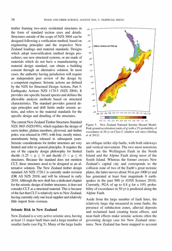
New Zealand is a very active seismic area, havingat least 11 major fault lines and a large number ofsmaller faults (see Fig 5). Many of the large faults
are oblique strike slip faults, with both sidewaysand vertical movement. The two most notoriousfaults are the Wellington Fault in the NorthIsland and the Alpine Fault along most of theSouth Island. Whereas the former crosses NewZealand’s capital city and corresponds to thecollision zone of two of the Earth’s great tectonicplates, the latter moves about 30 m per 1000 yr andhas generated at least four magnitude 8 earth-quakes in the past 900 yr (GNS Science 2018).Currently, PGA of up to 0.8 g for a 10% proba-bility of exceedance in 50 yr is predicted along theAlpine Fault.
Aside from the large number of fault lines, therelatively large slip measured in some faults, thepresence of subduction zones, alluvial depositsand reclaimed land creating basin effects, andnear-fault effects make seismic actions often thegoverning design case for New Zealand struc-tures. New Zealand has been mapped to account
Figure 5. New Zealand National Seismic Hazard Model:Peak ground acceleration (units of g) with a 2% probability ofexceedance in 50 yr on Class C (shallow soil sites) (Stirlinget al 2012).
WOOD AND FIBER SCIENCE, AUGUST 2018, V. 50(SPECIAL ISSUE)16

for the different seismic hazard levels, definedthrough the hazard factor Z. In addition, a near-faultfactorN needs to be taken into account for structuresclose to a known fault line. The relatively lowpopulation density somewhat mitigates the seismichazard exposure in New Zealand, but recentearthquakes such as the Canterbury Earthquakesequence in 2010 and 2011 and the KaikouraEarthquake in 2016 have led to code changes andincreased hazard factors in certain areas.
Seismic Design in New Zealand
Most buildings in New Zealand are designedaccording to the ELFP approach. This method isallowed for structures with a height of less than10 stories, when the building period is less than0.4 s, or when the structure is not classified asirregular and has a period smaller than 2 s. If theabove mentioned criteria are not satisfied, ora three-dimensional model is required, a modalresponse spectrum analysis is normally used. Theuse of time-history analysis is not uncommon forcomplex structures. A number of structures arealso designed based on the displacement-baseddesign philosophy (Priestley et al 2007), espe-cially for the case of innovative structural systems(base isolation, rocking structures, etc.). The useof DBD generally leads to a better understandingand control of the structural behavior underseismic loads. Currently this method is onlycodified for concrete rocking structures in the NewZealand concrete structures standards NZS3101(NZS 2006).
The elastic site spectra can be determined basedon the geographical location of the structure, therequired return period of the seismic event, andthe soil type. New Zealand has been subdividedinto areas with assigned hazard factors Z, rep-resenting the likely PGA of an earthquake. Insituations near known fault lines, the near-faultfactor N needs to be added to the equation. Infunction of the importance level of the structurea probable return period and respective returnperiod factor R of the ultimate limit state earth-quake is determined. Based on the soil charac-teristics the spectral shape factor is determined
depending on the building period. To obtain thedesign spectrum, the elastic spectrum is reducedby the inelastic spectrum factor kµ and thestructural performance factor Sp. The former isbased on the ductility and damping of thestructure and is also a function of the buildingperiod derived from the like-displacement andlike-energy assumptions. The latter is a perfor-mance factor and considers the probable higherstrength of materials, damping from nonstructuralelements, higher capacity from structural re-dundancy, nonstructural elements, etc. Differentformulations are given for the inelastic spectrumfactor kµ when using either equivalent staticanalysis or a modal response spectrum analysis.
When using equivalent static analysis, the baseshear is obtained by multiplying the horizontaldesign action coefficient from the design spec-trum by the expected seismic mass. The equiv-alent static forces can then be determined bydistributing the base shear proportional to theheight and mass of each floor up the building. Toallow for the possible presence of higher modeeffects, 8% of the base shear is applied to the topstory. Capacity design principles and strengthhierarchies need to be considered when designingductile structures. Some allowance is made forhigher mode effects in the equivalent staticmethod, but special studies might be required fortall and flexible structures. The loading standardalso differentiates between flexible and rigid di-aphragms and requires the specific considerationof diaphragm flexibility in the load distribution.
Seismic Design of CLT Buildings inNew Zealand
The use of CLT in New Zealand as a structuralmaterial only commenced in 2012with the opening ofthe first CLTmanufacturing plant in Nelson. Initially,the panels were mainly used as floor and roofingpanels; however, recently, a number of structures havebeen completed entirelywithCLT (Iqbal 2015; Parker2015). The last two years have seen an increasedinterest in massive timber structures, prompting theimport of CLT panels from Europe. Because of thenovelty of CLT and the respective fastening systems
Tannert et al—CROSS-LAMINATED TIMBER BUILDINGS 17

in New Zealand, no generally accepted design phi-losophy of CLT structures is available. Each design isbased on the individual designer’s engineeringjudgment, referencing international literature and of-ten using imported fasteners. Most of the early CLTstructures in New Zealand were designed eitherelastically or with limited ductility (µ ¼ 1.25). Be-causemost of these structureswere residential and hada large amount ofwalls, the higher seismic loads couldeasily be transferred and higher ductility values werenot necessarily targeted.
The other reason for using low seismic reductionfactors is that only limited information is available onthe ductility of proprietary fasteners, missing over-strength values, and lack of definition of brittle failuremodes of CLT panels. Furthermore, the currenttimber design standard only specifically mentionsnails as ductile fasteners, providing no information onthe yielding failure modes of other fasteners. Thesoon-to-be-released new timber code allows for theuse of the EYM, and as long as fastener ductility canbe guaranteed, higher building ductility can be used.
Only for the recent multistory CLT structures(Dunedin Student Accommodation in Dunedinand Arvida Parklane in Christchurch) higherductility values of two and three, respectively,were targeted. This was only possible by con-trolling the local ductility in the hold-downs byusing the EYM, avoiding brittle failure modes inthe panels by rational design of the highlystressed areas and using overstrength factors, andby taking into consideration all other elastic de-formation contributions when verifying the globalductility. Testing at the University of Canterburywill provide better understanding of the over-strength of dowel connection in CLT and brittlefailure modes (Ottenhaus et al 2018). Thisinformation, together with the new timber designstandard will allow engineers to design CLT struc-tures with more confidence under seismic actions.
DESIGN PROVISIONS IN CHILE
Regulatory Framework in Chile
The structural design of buildings in Chile isregulated by the General Law of Urban Planning
and Construction (DFL N°458) and the GeneralUrbanPlanning andConstructionOrdinance (OGUC)(DS N°47). The latter document includes a series oftechnical standards whose compliance must be veri-fied by the structural calculation project reviewer. Thisset of standards is composed of those that specify theloads that must be considered in the design and thestandards for each material (reinforced concrete, steel,and wood) that must be adhered to. The OGUCcontains specific indications for the construction ofwooden structures of no more than two stories, inwhich no structural calculation is required and in-cludes a series of requirements related to the protectionof buildings against fire. In addition, OGUC estab-lishes that for cases where there are no Chileantechnical standards applicable, the structural calcula-tion must be carried out on the basis of foreignstandards. Regarding the design of wood structures,the applicableChilean standard (NCh11982007) doesnot contain any regulations for the design of structuresinCLT; however, the use ofwood in any constructionsystem is permitted, provided that the structural designcomplies with the OGUC requirements.
Seismic Risk in Chile
Chile is one of the most seismic vulnerablecountries in the world; on average, every tenyears an earthquake of magnitude greater thaneight occurs. The high level of seismicity wasdocumented by the more than 4000 earthquakesof magnitude greater than five recorded between1962 and 1995 (Madariaga 1998), and more than8000 earthquakes of magnitude greater than threein 2017. In this context, the largest seismic eventever to be recorded occurred in southern Chile in1960, with a magnitude greater than 9.5. Thegreatest seismic activity in Chile is due to thesubduction of the Nazca plate under the SouthAmerican plate with an estimated speed ofconvergence between these plates of 60-70 mmper year (Khazaradse and Klotz 2003). Theseismic activity in the country, to the south of theTaitao peninsula, which is lower than that oc-curring in the central and northern zone of Chile,is produced by subduction of the Antarctic plateunder the South American plate and by sliding of
WOOD AND FIBER SCIENCE, AUGUST 2018, V. 50(SPECIAL ISSUE)18
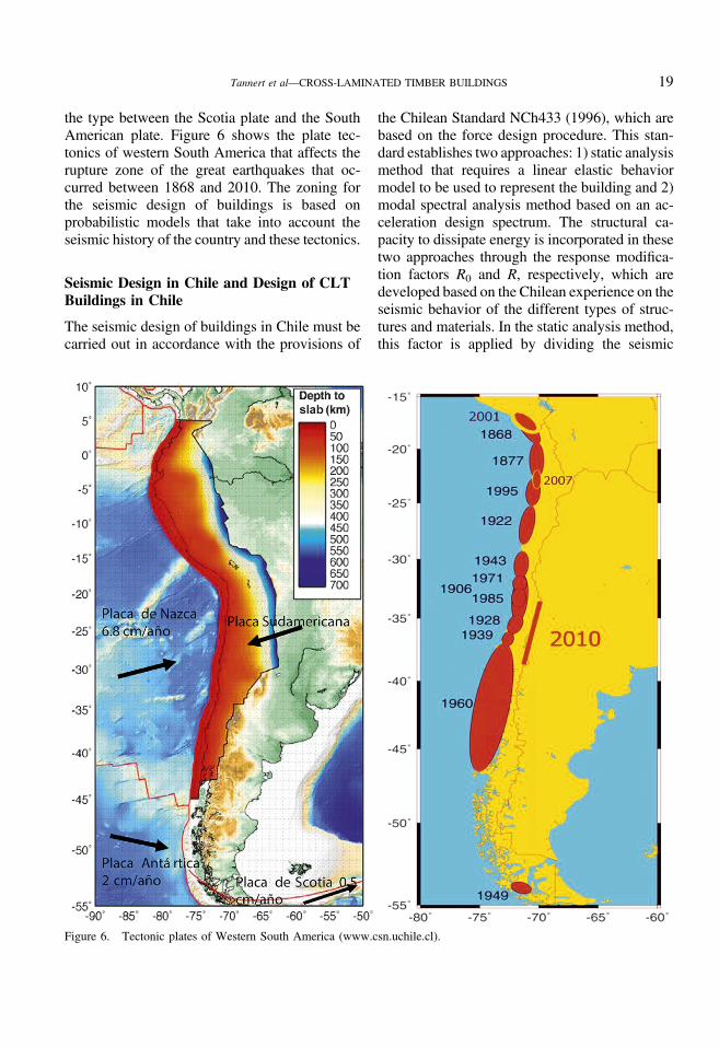
the type between the Scotia plate and the SouthAmerican plate. Figure 6 shows the plate tec-tonics of western South America that affects therupture zone of the great earthquakes that oc-curred between 1868 and 2010. The zoning forthe seismic design of buildings is based onprobabilistic models that take into account theseismic history of the country and these tectonics.
Seismic Design in Chile and Design of CLTBuildings in Chile
The seismic design of buildings in Chile must becarried out in accordance with the provisions of
the Chilean Standard NCh433 (1996), which arebased on the force design procedure. This stan-dard establishes two approaches: 1) static analysismethod that requires a linear elastic behaviormodel to be used to represent the building and 2)modal spectral analysis method based on an ac-celeration design spectrum. The structural ca-pacity to dissipate energy is incorporated in thesetwo approaches through the response modifica-tion factors R0 and R, respectively, which aredeveloped based on the Chilean experience on theseismic behavior of the different types of struc-tures and materials. In the static analysis method,this factor is applied by dividing the seismic
Figure 6. Tectonic plates of Western South America (www.csn.uchile.cl).
Tannert et al—CROSS-LAMINATED TIMBER BUILDINGS 19
coefficient by the value that corresponds to thestructural system and the building material. In thecase of the modal spectral analysis method,the modification factor is contained in the de-nominator of the expression of the accelerationdesign.
The general provisions of NCh433 applied inconjunction with the specific material designstandards are aimed at achieving structures thatmeet the following three conditions: 1) resistwithout damage seismic movements of moderateintensity; 2) limit damage to nonstructural ele-ments during moderate intensity earthquakes; 3)avoid collapse during earthquakes of exception-ally severe intensity. The norm states that “Eventhough three levels of seismic intensity arementioned, this norm does not define them ex-plicitly.” Regarding the seismic design of woodenbuildings, NCh433 only contains values of re-sponse modification factor for light-frame andbraced structures. As there are currently no specificregulations for the design of CLT buildingsavailable in Chile, the provisions of NCh433 andthe requirements specified in OGUC must be usedfor the seismic design of CLT buildings.
DESIGN PROVISIONS IN CHINA
Regulatory Framework in China
The Standardization Administration of the Peo-ple’s Republic of China defines the nationalstandard management regulations and requirementsand has the task to manage and produce technicalspecifications for products and systems for theconstruction sector. The Chinese EngineeringStandards are divided into national standards, oc-cupation standards, local standards, and enterprisestandards. National standards shall be appliedthroughout the country, and other standards shallnot conflict with national standards. For buildingdesign and construction, the Ministry of Housingand Urban-Rural Development of China enacteda set of specific and uniform regulations (labeledJGJ), whereas the Forestry Bureau is responsiblefor wood product standards and testing methods(labeled LY). Chinese Engineering Standardsare divided into two categories of mandatory
standards (labeled GB) and recommended stan-dards (labeled T). For timber structures, applicablestandards are the “Code for design of timberstructures” (GB 50005 2017) and the “TechnicalStandard for Multi-story and High Rise TimberBuildings” (GB/T 51226 2017). These standardsare updated every five or ten years based on sci-entific and technological advances. The Code forseismic design of building structures (GB 50011-2008) was revised and updated based on theWenchuan Earthquake hazard survey and thelatest seismic disaster mitigation technology.
Seismic Risk in China
China is located between the Circum-Pacific andthe Eurasian seismic zones, which are two of themost active seismic zones in the world. Accordingto historical earthquake records, Taiwan has themost earthquakes, followed by Xinjiang and Tibet,and coastal areas of China (Zhang et al 2009).According to the Seismic Fortification IntensityZonation Map of China (2016), 7% of the totalland area is considered at risk of magnitude eightearthquakes and 1% of the total land area isconsidered at risk of magnitude nine earthquakes(see Fig 7). Examples of large earthquakes arethe magnitude 7.8 Tangshan Earthquake that in1976 struck Tangshan, Hebei Province andsurrounding regions, obliterated the city ofTangshan and killed more than 240,000 people,making it the deadliest earthquake of thetwentieth century. In 2008, the Wenchuan 8.0magnitude earthquake occurred in Sichuanprovince and caused the collapse of about 6.5million buildings and the death of nearly 70,000people (CEA 2018).
Seismic Design in China
Seismic design of buildings is performed to mini-mize damage and loss of lives and properties. InChina, the design philosophy of “three-level andtwo-stage” is widely used in the Chinese nationalcode, Code for Seismic Design of Building (GB50011): Level 1) structures are subjected to frequently
WOOD AND FIBER SCIENCE, AUGUST 2018, V. 50(SPECIAL ISSUE)20

occurring earthquakes (in a design period of fiftyyears, the exceedance probability is approximately63.2% with a return period of 50 yr)—the struc-tures either will be in service or only slightlydamaged; Level 2) structures are subjected to thefortification earthquakes (in a design period of fiftyyears, the exceedance probability is approximately10% with a return period of 475 yr)—the structuremay be damaged but they should be serviceablewith repair; and Level 3) structures are subjected torarely occurring earthquakes (in a design period offifty years, the exceedance probability is approx-imately 2-3% with a return period of 1642-2475yr), they will neither collapse nor suffer damagethat would threaten human lives. The “two stages”can be given as follows: Stage 1) The capacity andlateral drifts of a building structure should beexamined under the basic load combination con-sidering frequently occurring earthquakes by usingthe assumption of elastic performance ofmembers and connections; and Stage 2) Theelasto-plastic lateral drifts along the height of any
building should be examined under rarely occurringearthquake conditions.
The method adopted in the Chinese SeismicDesign Code determines the seismic forces actingon a structure using an indirect approach bytransforming the earthquake-induced dynamicproblem into a static problem under static load.Based on the acceleration responses due toground motions, the inertia force of a structuralsystem can be calculated and regarded as anequivalent load, which reflects the effects ofthe earthquake. The elastic acceleration spectrumis substituted by an earthquake influence coeffi-cient, α, defined as the ratio of the horizontalseismic force acting on a single elastic systemto that of gravity. The damping adjustmentand parameter formations on the building seis-mic influence coefficient curve are provided bya graphical representation. For buildings withlong periods, the decrease of α is considered inseismic influence coefficient curve.
Figure 7. 2016 seismic zoning map A of China (http://www.hundzj.gov.cn/).
Tannert et al—CROSS-LAMINATED TIMBER BUILDINGS 21
Seismic Design of CLT Buildings in China
With the development and application of CLTworldwide, Chinese scholars started to do re-search on manufacturing processes, materialproperties of CLT, panel and connection struc-tural performance, and seismic performance ofCLT and mixed structures (He et al 2016; Xionget al 2016a). A parametric study and time-historyanalysis of a tall CLT frame and concrete coremixed structural system showed that the verticalvibration and displacement compatibility of thehybrid structure are the special issues that shouldbe considered. To substitute concrete and/or steelfor wood in high density cities in China, an in-novative super tall building with concrete frame-and-core structure inserted with CLT modularsubstructures was proposed and preliminarilydesigned (Xiong et al 2016b). The Chinese na-tional standards GB 50005 (2017) and GB/T51226 (2017) incorporated these findings andspecify the requirements for CLT material prop-erties, structural systems, and basic requirementsof building height and design methodology ofCLT structures.
CONCLUSIONS
In Europe, the current version of the structuralEurocode related to the seismic design of struc-tures, EC8, is subjected to a comprehensive re-view, together with the other Eurocodes, and thenew version will be released by 2021. Regardingthe seismic design of CLT buildings, the newdesign rules will provide a significant improve-ment, including capacity-based design rules,detailing provisions and overstrength factors fordissipative zones which are currently totallymissing for most of the structural types. Moreoverthe new standard will include a revision of thevalues of the behavior factors q and a clarificationof the concept of static ductility and proposal ofminimum values needed at the different scales(fastener, joint, and subassembly) to attaina certain value of the behavior factor and someguidance on the application of nonlinear staticand dynamic analysis methods to timber struc-tures. However, improvements are still neededespecially regarding the seismic design and detailing
of nonstructural elements; provisions for theuse of displacement-based design, particularlyfor tall buildings; provisions for the seismicdesign of innovative low-damage structuralsystems; and recommendations for the esti-mation of the connection ductility in the dis-sipative regions.
In Canada, providing seismic design provisionsinto the wood design standard CSA-O86 (CSAO86 2016) presented a significant accomplish-ment. Nevertheless, there are several aspectswhere designers need further guidance. Thestandard refers to “methods of mechanics” and“engineering principles of equilibrium and dis-placement compatibility” but comes short ofspecific guidance. CSA-O86 does not providedesign procedures for the resistance and de-formation of LLRS composed of CLT and nospecific guidance on how to facilitate the targetedkinematic mode a CLTwall will experience in thepresence of vertical loads, especially for multi-panel walls, where the kinematic behavior maychange during the loading as a function of theconnection behavior. CSA-O86 does providecapacity-based design provisions that require theknowledge of 95th percentile connection strengthvalues to ensure that they will remain elasticwhen the dissipative connectors have reachedtheir ultimate resistance or target displacement,yet the standard does not provide the values forany connections. The designer need, therefore, torely on test data obtained from the fastenermanufacturer. As a cautionary note, it must bementioned that NBCC is not yet referencing thecurrent CSA-O86 standard and that furtherchanges related to acceptable kinematic motionsof CLT shear walls and the acceptable CLT panelaspect ratios might be introduced into the 2019edition of CSA-O86.
In the United States, posttensioned rocking wallshave received some attention with a recent studythat examined the feasibility of designing up to 10stories with this approach (Pei et al 2015).Supporting numerical models for that study weredeveloped and a new study is underway thatfocuses on bidirectional assembly level testing,two-story shake table testing (Akbas et al 2017;
WOOD AND FIBER SCIENCE, AUGUST 2018, V. 50(SPECIAL ISSUE)22

Ganey et al 2017), and will culminate by vali-dating a resilience-based seismic design philos-ophy for tall wood buildings constructed of CLTwith posttensioned CLT walls by testing a full-scale 10-story building on a shake table in 2020.The approaches developed within that projectwill serve as a guideline to approach buildingofficials for midrise and tall wood buildingconstruction under the alternative methods pro-vision in ASCE 7.
In New Zealand, the use of CLT is relatively newwith only one local supplier available. BecauseCLT is not codified in New Zealand, only a smallnumber of engineers are taking the lead on theseismic design of these structures, normally re-quiring a peer review to obtain building consent.Although the seismic risk in New Zealand is highto very high, most CLT structures are currentlydesigned elastically or with only limited ductilitytargets. Higher ductility levels are often not re-quired because of the limited size of the structures
with only up to two storys and the large numberof walls. The lack of guidance on the seismicdesign, missing overstrength factors, and limitedknowledge on the brittle failure modes of CLTdiscourages the use of higher ductility levels.Although current research on the cyclic behaviorof large force connections show promising resultsin terms of capacity and ductility, more in-formation on overstrength and brittle failuremodes is required to provide confidence in de-signing tall and large CLT structures. Higherductility levels have been targeted through theuse of innovative systems. An example of this isthe Kaikoura District Council building (Iqbal2015), which was designed using posttensioned,Pres-Lam walls and a displacement-based designapproach. This building was subjected to the re-cent Kaikoura earthquake in 2016 with no signs ofvisible damage.
In Chile, to support the development of designguidelines for CLT structures, the government,
Table 1. Main differences in seismic design approaches and regulations.
Country/regionStatus of CLT seismicdesign provisions
Applicable seismic forcereduction factors
Scope of CLT seismic designstandard provisions
Europe Proposal in development forinclusion into EC8
q ¼ 2.0 (DCM) No height limitation, panel aspect ratio1:5 to 4:1, and capacity protectionusing 1.3 overstrength factor
q ¼ 3.0 (DCM)
Canada Regulated in CSA-O86 since2016
Rd Ro ¼ 3.0 (for structureswithin scope)
Height <30 m in low seismic regions;<20 m in high seismic regions;panel aspect ratio 1:1 to 4:1, andcapacity protection using 95thstrength percentile
Rd Ro ¼ 1.3 (otherwise)
UnitedStates
Proposal in development forinclusion into AmericanSociety of Civil EngineersStandard 7
R ¼ 3.0-3.5 depending on theresults of the FEMA P695analysis and peer review
Height <20 m panel aspect ratio 2:1 to4:1 and capacity protection using1.15 for overturning restraint. Shearconnectors not assumed to take anyuplift
Japan Notification 611, No.8 Ds ¼ 0.4-0.55 (¼1/R) dependingon connectors, 0.75 for allstructure
0.4-0.55: Connectors for bendingmoment are required with tensileratio of 10%
NewZealand
CLT will not be included in2018 current update
Connections with global ductilityvalues of up to 3 are available
—
Chile No CLT specific provisionsin standard
R ¼ 2.0 as default value for anystructural system
—
China Regulated in GB/T 512262017
Different approach to calculationof seismic forces without forcereduction factors
Heights up to 56 m depending onseismic intensity and structuralsystem, panel aspect ratio 1:2 to 3:1,and capacity protection using 1/0.85overstrength factor
CLT, cross-laminated timber; DCM, ductility classes medium.
Tannert et al—CROSS-LAMINATED TIMBER BUILDINGS 23

through the Development Corporation, hassupported projects to determine the physicaland mechanical properties of CLT using radiatapine, and to analyze the dynamic behavior ofthe CLT panel systems (Gonzalez et al 2014;Perez et al 2017) and develop a four-storybuilding in CLT for social housing (Pinaet al 2015). In China, the first actual CLT-steel hybrid structure “OTTO cafe” of Chinawas built in Ningbo. The design was the workof the first prize of the First National De-sign Competition of Timber Structures foruniversity students. With the policy supportand development of materials and constructiontechniques, several multistory CLT buildings havingbeen designed and will be built soon.
The previous discussion demonstrated that theincreasing interest in and demand for CLTstructures worldwide has produced a large bodyof research knowledge that is being integratedinto design provisions. Many studies confirmedthe good structural performance of CLT struc-tures, including good seismic performance whenusing ductile connectors. As a consequence, CLTis increasingly gaining popularity in single andmultistory residential and nonresidential ap-plications worldwide, also in areas with highseismic activity. Designing and building CLTstructures, also in earthquake-prone regions, is nolonger a domain for early adopters, but is be-coming a part of regular timber engineeringpractice. The increasing interest in CLT con-struction has resulted in multiple regions andcountries adopting provisions for CLT into theirengineering design standards. However, giventhe economic and legal differences betweeneach region, some fundamental issues are treateddifferently, particularly with respect to seismicdesign. Table 1 summarizes the main differencesin the seismic design approaches and regulationsfor the regions that were presented in this article.
REFERENCES
Adams J, Halchuk S, Allen T, Rogers GC (2015) Canada’s5th generation seismic hazard model, as prepared for the2015 National Building Code of Canada in Proc. of the11th Canadian Conference on Earthquake Engineering,July 21-24, 2015, Victoria, BC, Canada.
Akbas T, Sause R, Ricles J, Ganey R, Berman J, Lotus S,Dolan JD, Pei S, van de Lindt J, Blomgren H (2017)Analytical and experimental lateral load response of self-centering CLT walls. J Struct Eng 143(6):04017019.
Amini MO, van de Lindt JW, Rammer D, Pei S, Line P,Popovski M (2016) Determination of seismic performancefactors for CLT building systems. WCTE 2016, Vienna,Austria.
ANSI/APA (2017) PRG 320, Standards for performance-rated cross-laminated timber. American National Standard,APA, Tacoma, WA.
ASCE (2016) Minimum design loads for building and otherstructures. ASCE Standard ASC/SEI 7-16, AmericanSociety of Civil Engineers, Reston, VA.
BCBC (2012) Building code of British Columbia, Office ofhousing and construction standards. National ResearchCouncil, Victoria, BC, Canada.
Brandner R, Flatscher G, Ringhofer A, Schickhofer G, ThielA (2016) Cross laminated timber (CLT): Overview anddevelopment. Eur J Wood Wood Prod 74(3):331-351.
BSL Article 20 (2015) Guideline for building standard law,enforcement order and notification for structural design,p. 25, Article 20, Official Gazette Co-operation of Japan.
BSL Article 37 (2015) Guideline for building standard law,enforcement order and notification for structural design,p. 48, Article 37, Official Gazette Co-operation of Japan.
BSL (2016) Japan ministry of land, infrastructure, transportand tourism, building standard law. The Building StandardLaw of Japan, Building Center of Japan, Tokyo, Japan.
Cassidy JF, et al. (2010) Canada’s earthquakes: ‘The good,the bad, and the ugly’. Geoscience Canada 37(1):1911-4850.
CEA (2018) China earthquake administration. http://www.cea.gov.cn/ (accessed November 2017).
Ceccotti A, Follesa M (2006) Seismic behaviour of multi-storey XLam buildings in Proc. COST Action E29,International Workshop—Earthquake Engineering onTimber Structures, pages 81-95, Coimbra, Portugal.
Ceccotti A, Sandhaas C, Okabe M, Yasumura M, Minowa C,Kawai N (2013) SOFIE project–3D shaking table test ona seven-storey full-scale cross-laminated timber building.Earthquake Eng Struct Dyn 42(13):2003-2021.
CEN (2001) EN 12512: 2001. Timber structures—Testmethods—Cyclic testing of joints made with mechanicalfasteners. European Committee for Standardization, Brussels,Belgium.
CEN (2004) Eurocode 8: Design of structures for earthquakeresistance, Part 1: General rules, seismic actions and rulesfor buildings. European Committee for Standardization,Brussels, Belgium.
CEN (2008) EN 1995-1-1:2008. Eurocode 5: Design oftimber structures—Part 1-1: General—Common rules andrules for buildings. European Committee for Standardi-zation, Brussels, Belgium.
Centro Sismologico Nacional (2018) Sismicidad y terre-motos en Chile. Centro Sismologico Nacional/Universidadde Chile, Santiago, Chile.
WOOD AND FIBER SCIENCE, AUGUST 2018, V. 50(SPECIAL ISSUE)24

CSA O86 (2014) Engineering design in wood. CanadianStandards Association, Ottawa, Canada.
CSA O86 (2016) Supplement. Engineering design in wood.Canadian Standards Association, Ottawa, Canada.
DFL N° 458 (1975) Ley General de Urbanismo yConstrucciones.
Dimova S, FuchsM, Pinto A, Sousa L, Nikolova B, IannacconeS (2015) State of implementation of the Eurocodes in theEuropean Union: Support to the implementation, harmoni-zation and further development of the Eurocodes. Report2015. EUR 27511. doi:10.2788/85493.
DR AS NZS (2018) Timber structures-Part 1: Design methods.Standards New Zealand, 1720.1, Wellington, New Zealand.
DS N°47 Ministerio de Vivienda y Urbanismo (2017)Normativa de Urbanismo y Construcciones.
EN 16351 (2015) Timber structures—Cross-laminatedtimber—Requirements. European Committee for Stan-dardization, Brussels, Belgium.
European Union (2011) Regulation (EU) No 305/2011 of theEuropean Parliament and of the Council of 9 March 2011laying down harmonised conditions for the marketing ofconstruction products and repealing Council Directive89/106/EEC, European Union, Brussels, Belgium.
European Union (2016) The European construction sector. Aglobal partner. Internal market, industry, entrepreneurshipand SMEs directorate general energy directorate general.Joint Research Centre (JRC). https://ec.europa.eu (accessedNovember 2017).
FDMA, Fire andDisasterManagementAgency (2006)Hanshin-Awaji Great Earthquake. www.fdma.go.jp/bn/1995/detail/941.html (accessed November 2017).
FDMA, Fire and Disaster Management Agency (2016)Higashi Nihon Great Earthquake. www.fdma.go.jp/bn/higaihou.html (accessed November 2017).
FEMA (2009) Quantification of building seismic perfor-mance factors: FEMA P695. Federal Emergency Man-agement Agency, Washington, D.C.
Follesa M, Fragiacomo M, Casagrande D, Canetti D, TomasiR, Piazza M, Vassallo D, Rossi S (2018) The new pro-visions for the seismic design of timber buildings inEurope. Engineering Structures, Special issue.
Follesa M, Fragiacomo M, Vassallo D, Piazza M, Tomasi R,Rossi S, Casagrande D (2015) A proposal for a newbackground document of chapter 8 of Eurocode 8, paper48-7-3 in Proc. 2nd International Network on TimberEngineering Research (INTER), Sibenik, Croatia.
Gagnon S, Pirvu C (2012) Cross-laminated timber (CLT)handbook. FPInnovations, Vancouver, Canada. 594 pp.
Ganey R, Berman J, Akbas T, Loftus S, Daniel Dolan J,Sause R, Blomgren HE (2017) Experimental investigationof self-centering cross-laminated timber walls. J Struct Eng143(10):04017135.
Gavric I, Fragiacomo M, Ceccotti A (2015) Cyclic behaviorof CLT wall systems: Experimental tests and analyticalprediction models. J Struct Eng 141(11):04015034.
GB 18306-2016 (2016) Seismic ground motion parameterzonation map of China. National Standard of the People’sRepublic of China, China Criterion Press, Beijing, China.
GB 50005 (2017) Code for design of timber structures. ChinaArchitecture and Building Press, Beijing, China.
GB 50011 (2001) Code for seismic design of buildings,National Standard of the People’s Republic of China,China Building Industry Press, Beijing, China.
GB/T 51226 (2017) Multi-story and high rise timber build-ings. China Architecture and Building Press, Beijing, China.
Giardini D, Woessner J, Danciu L, Cotton F, Crowley H,Grunthal G, Stucchi M (2013) Seismic Hazard Harmo-nization in Europe (SHARE): Online Data Resource. doi:10.12686/SED-00000001-SHARE.
GNSScience (2018)Major faults inNewZealand. https://www.gns.cri.nz/Home/Learning/Science-Topics/Earthquakes/Major-Faults-in-New-Zealand (accessedNovember 2017).
Gonzalez P, Saavedra E, Perez E, Burgos C, Piña F, WagnerM (2014) Sistema constructivo en madera contralaminadapara edificios. Servicios Forestales y de Exposiciones S.A.,Santiago, Chile.
He M, Duo T, Zheng L (2016) State-of-the-art of researchadvances on multi-story timber and timber-hybrid struc-tures. J Build Struct 37(10):1-9.
HERP (2017) Japanese Headquarters for Earthquake ResearchPromotion Report National Seismic Hazar Maps for Japan.www.jishin.go.jp/main/index-e.html (accessed November2017).
HOWTEC (2016a) Guideline for 2016 CLT relative notifi-cations. Japan Housing and Wood Technology Center,Tokyo, Japan.
HOWTEC (2016b) Design and construction manual for CLTbuildings. Japan Housing and Wood Technology Center.
Hummel J (2017) Displacement-based seismic design formulti-storey cross-laminated timber buildings. PhD thesis,Kassel University Press, Kassel, Germany. 224 pp.
International Building Code (IBC) (2018) International CodeCouncil, Washington, D.C.
Iqbal A (2015) Cross-laminated timber for building struc-tures. SR336. BRANZ Report.
Kawai N, Miyake T, Yasumura M, Isoda H, Koshihara M,Nakajima S, Araki Y, Nakagawa T, Sato M (2016) Fullscale shake table tests on five story and three story CLTbuilding structures in Proc. 14th World Conference onTimber Engineering, August 22-25, 2016, Vienna, Austria.
Khazaradse G, Klotz J (2003) Short and long-term effects ofGPS measured crustal deformation rates along the south-central Andes. J Geophys Res 108(B6):1-15.
Johansen KW (1949) Theory of timber connections. IntAssoc Bridge Struct Eng 9:249-262.
LauriolaMP,SandhaasC (2006)Quasi-static and pseudo-dynamictests onXLAMwalls and buildings in Proc. COSTAction E29,International Workshop—Earthquake Engineering on TimberStructures, pages 119-133, Coimbra, Portugal.
Luco N, Ellingwood BR, Hamburger RO, Hooper JD,Kimball JK, Kircher CA (2007) Risk-targeted versuscurrent seismic design maps for the conterminous United
Tannert et al—CROSS-LAMINATED TIMBER BUILDINGS 25

States in Proc. Structural Engineers Association of CaliforniaConvention, Sacramento, CA.
Madariaga R (1998) Sismicidad de Chile. Fis Tierra 10:221-258.
Meyer A (1957) Die Tragfahigkeit von Nagelverbindungenbei statischer Belastung. Holz Roh Werkst 15(2):96-109.
Miyake T, Yasumura M, Kawai N, Isoda H, Koshihara M,Tsuchimoto T, Araki Y, Nakagawa T (2016) Structuralpossibility of CLT panel constructions in High seismicarea in Proc. 14th World Conference on Timber Engi-neering, August 22-25, 2016, Vienna, Austria.
Moroder D, Smith T, Dunbar A, Pampanin S, Buchanan A(2018) Seismic testing of post-tensioned Pres-Lam corewalls using cross laminated timber. Eng Struct 167:639-654.
NCh1198 (2007)Madera—Construcciones enmadera—Calculo.Instituto Nacional de Normalizacion INN-Chile, Santiago deChile.
NCh433 (1996) Diseno sismico de edificios. Instituto NacionalDe Normalizacion, INN-Chile, Santiago de Chile.
NDS (2018) National design specification for wood con-struction. American National Standards Institute/AmericanWood Council (ANSI/AWC), Leesburg, VA.
NRC (2015) National building code of Canada 2015, Ca-nadian commission on building and fire codes. NationalResearch Council, Ottawa, Canada.
NRCAN (2016) Geological survey of Canada earthquakesearch (On-line Bulletin). Natural Resources Canada.http://earthquakescanada.nrcan.gc.ca/stndon/NEDB-BNDS/bull-eng.php.52 (accessed November 2017).
NZBC (2004) New Zealand building code. New ZealandGovernment, Wellington, New Zealand.
NZS (1993) 3603. Timber structures standard. StandardAssociation of New Zealand, Wellington, New Zealand.
NZS (2004) 1170.5. Structural design actions. Part 5:Earthquake actions—New Zealand. Standard Associationof New Zealand, Wellington, New Zealand.
NZS (2006) 3101. Concrete structures standard Parts 1 & 2:The Design of concrete structures and commentary.Standard Association of New Zealand, Wellington, NewZealand.
NZS (2011) 3604. Timber framed buildings. Standard As-sociation of New Zealand, Wellington, New Zealand.
Ottenhaus LM, Li M, Smith T, Quenneville P (2018)Overstrength of dowelled CLT connections undermonotonic and cyclic loading. Bull Earthquake Eng 16(2):753-773.
Parker J (2015) Timber takes on new forms. BRANZ, BuildMagazine. Build 149.
Pei S, Lenon C, Kingsley G, Deng P (2017) Seismic design ofcross-laminated timber platform buildings using a coupledshear wall concept. J Archit Eng 23(3):06017001.
Pei S, van de Lindt JW, Popovski M (2013) ApproximateR-factor for cross-laminated timber walls in multistorybuildings. J Archit Eng 19(4):245-255.
Pei S, van de Lindt JW, Popovski M, Berman JW, Dolan JD,Ricles JM, Sause R, Blomgren H-E, Rammer DR (2015)
Cross laminated timber for seismic regions: Progress andchallenges for research and implementation. J Struct Eng142:E2514001.
Perez E, Gonzalez P, Saavedra E, Tapia S, Torelli S, OrellanaS (2017) Mechanical characterization and hysteretic be-haviour of CLT panels made of Chilean radiata pine inProc. 16th World Conference on Earthquake Engineering,January 9-13, 2017, Santiago, Chile.
Pina F, Gonzalez P, Burgos C, Saavedra E (2015) Seismicdesign of amid-rise building inChile using radiate pine crosslaminated timber in Proc. 11th Canadian Conference onEarthquake Engineering, July 21-24, 2015, BC, Canada.
Popovski M, Gavric I (2015) Performance of a 2-story CLThouse subjected to lateral loads. J Struct Eng 142(4):E4015006.
Popovski M, Schneider J, Schweinsteiger M (2010) Lateralload resistance of cross laminated wood panels. Pages 20-21,Curran Associates in Proc. 11th World Conference on TimberEngineering, June 20-24, 2010, Riva del Garda, Italy.
Priestley MJN, Calvi GM, Kowalsky MJ (2007) Displacement-based seismic design of structures. IUSS Press, Pavia, Italy.721 pp.
SDPWS (2015) ANSI/AWC Special design provisions forwind and seismic. AmericanWood Council, Leesburg, VA.
Shahnewaz M, Tannert T, Alam MS, Popovski M (2017) In-plane stiffness of cross-laminated timber panels withopenings. Struct Eng Int 27(2):217-223.
Stirling M, McVerry G, Gerstenberger M, Litchfield N, VanDissen R, Berryman K, Lamarche G (2012) Nationalseismic hazard model for New Zealand: 2010 Update. BullSeismol Soc Am 102(4):1514-1542.
van de Lindt JW, Amini MO, Rammer D, Pei S, Line P,Popovski M (2016) Progress in developing seismic per-formance factors for cross laminated timber in the UnitedStates via the FEMA P695 methodology in Proc. ASCEStructures Congress, April 3-5, Boston, MA.
Woessner J, Laurentiu D, Giardini D, Crowley H, Cotton F,Grunthal G, Hiemer S (2015) The 2013 European seismichazard model: key components and results. Bull Earth-quake Eng 13(12):3553-3596.
Xiong H, Ouyang L, Wu Y (2016a) State-of-the-art on re-search of tall wood buildings. J Tongji Univ 44(9):1297-1306. (Natural Science).
Xiong H, Ouyang L, Wu Y (2016b) Preliminary design ofa novel hybrid tall building with concrete frame-tube andlight wood boxes in Proc. World Conference on TimberEngineering, August 22-25, 2016, Vienna, Austria.
Yasumura M, Kobayashi K, Okabe M, Miyake T, MatsumotoK (2015) Full-scale tests and numerical analysis of low-riseCLT structures under lateral loading. J Struct Eng 142(4):E4015007.
Zhang X, Yang G, Lu X, Li M, Yang Z (2009) Relationbetween the characteristics of strong earthquake activitiesin Chinese mainland and the Wenchuan earthquake.J Earth Sci 22:505-518.
WOOD AND FIBER SCIENCE, AUGUST 2018, V. 50(SPECIAL ISSUE)26