sÜdmo dsv complete double seat valves - …/media/websites/...dsv complete double seat valves 3 in...
TRANSCRIPT

FLOW & FILTRATION SOLUTIONS PROCESS VALVE TECHNOLOGY
SÜDMO DSV COMPLETE DOUBLE SEAT VALVES

2
Based on its many years of experience in valve construction, Südmo offers a comprehensive, refined double-seat valve for implementation and automation of widely varying production processes in the food and beverage industry.
Why use Südmo double seat valves?
As well as a wide range, the series is characterized by ease of handling and maintenance, and is therefore the ideal component for operating your processes with maximum efficiency and safety.
DOUBLE SEAT VALVE SERIES DSV COMPLETE
The function of the double-seat valve is shown in the below tank farm application example.
Simultaneous, programmed filling, emptying and cleaning of four production lines without risk of mixing. Reliable separation of upper and lower valve housing allows one or more lines or tanks (purple and red lines) to be cleaned during production (yellow and green lines).
GENERAL REQUIREMENTS FOR HYGIENIC DOUBLE SEAT VALVES FUNCTION
• Reliable separation of two media (e.g. product and cleaning liquid) > Two sealing elements work separately > Leakage chamber open to atmosphere - Avoids pressure build-up - Visual leak detection
• All surfaces in contact with product can be cleaned
CIP SUPPLY
12
3
PRODUCT
CIP RETURN4

3D S V C O M P L E T E D O U B L E S E A T V A LV E S
In seat area
• Step seat with conical seal o-ring• Radial seat with RSC seal (Radial Seal
Complete) In shaft area
• Sealing by form-fit profile seal
• Cycle stroke with defined ring gap• Leakage chamber flushing via external
connection• Sterile chamber for shaft flushing /
sterilization• Shaft flushing of lower valve disc
INNOVATIVE SEALING CONCEPT SAFE CLEANING
HIGH PROCESS RELIABILITY LOW OPERATING COSTS SUSTAINED VALVE INNOVATION
HIGH OPERATING PRESSURES
• Open, close and seal up to 10 bar*• High pressure pulse resistance
* Depending on type and nominal width
• Durable pneumatic seals • Main spring chambered• All valve positions can be monitored
IntelliTop 2.0 control unit
• EHEDG
• 3A
• PMO
• ATEX
• CRN
• Official licences for use in milk heaters
• All seals comply with FDA standards
• Simple, rapid maintenance • No special tools needed• Easy handling thanks to compact
construction• Low maintenance costs (Opex)
OPTIMIZED DRIVE & CONTROL CONCEPT
LICENCES & CERTIFICATES
SERVICETOP QUALITY
• Body machined from solid bar stock• High surface quality • Reduced-friction surfaces on moving
parts• Design optimized for cleaning
53-04
R
53-04
R
65-00
R
65-00
R
85-00
R
85-00
R
PMO Section 7 Item 15p(B) compliant
This double-seat mixproof valve is designed for
steam sterilization
PMO Section 7 Item 15p(B) compliant
This double-seat mixproof valve is designed for
steam sterilization
4
Sitzbereich
Leckageauslauf
Radialdichtring „RSC“
Formschlüssig gestützte Profildichtung
LanglebigePneumatikdichtungen
Einteiliges massivesVentilgehäuse
Metallischdefinierter Ringspalt
Schließhülse(oberer Ventilteller)
Gekammerte Hauptfeder
Formschlüssig gestützte Profildichtung
Luftanschluss Haupthub
Luftanschluss TakthubOberer Ventilteller
Luftanschluss TakthubUnterer Ventilteller
IntelliTop 2.0 ® zur Ansteuerungder Hübe und Stellungsrückmeldung
Valve disc (lower valve disc)
Upper shaft passage
Lower shaft passage
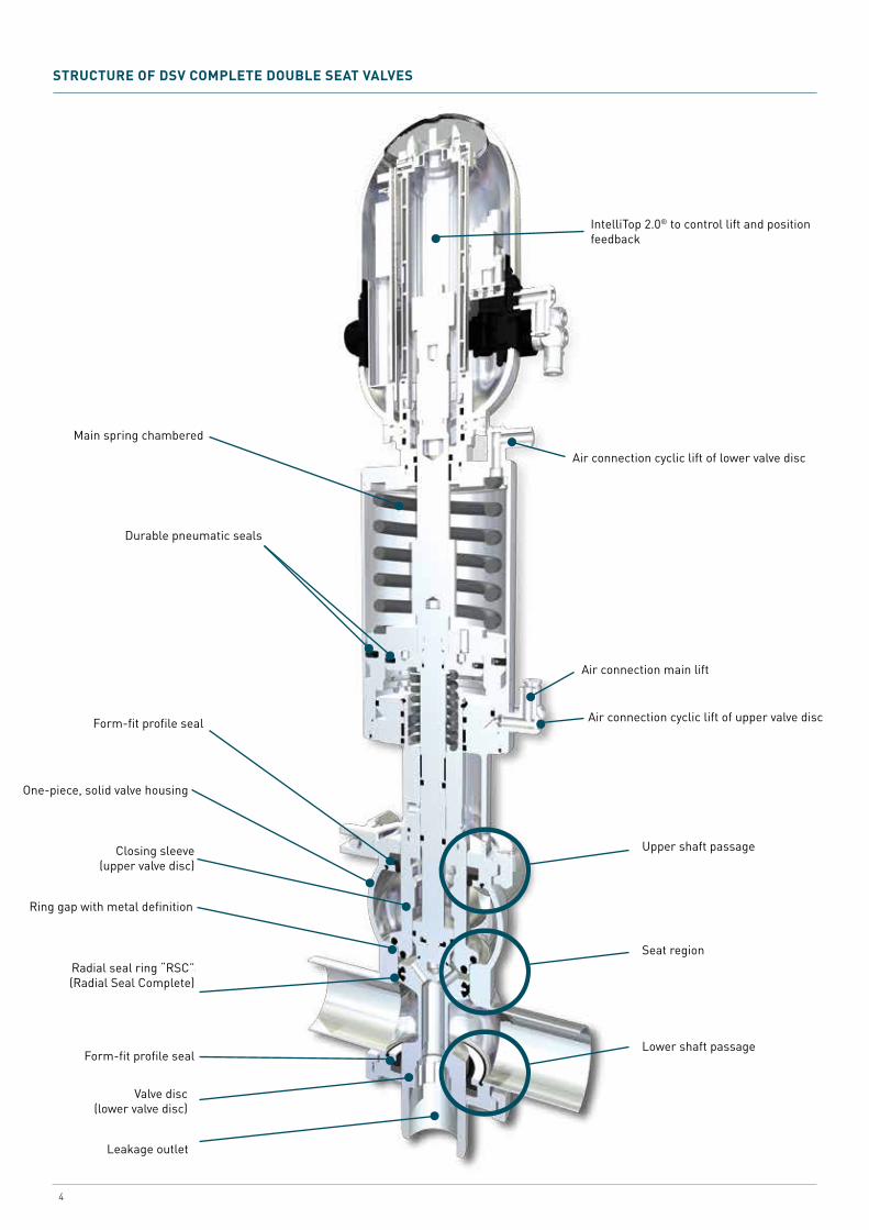
STRUCTURE OF DSV COMPLETE DOUBLE SEAT VALVES
Radial seal ring “RSC” (Radial Seal Complete)
IntelliTop 2.0® to control lift and position feedback
Air connection cyclic lift of lower valve disc
Air connection main lift
Air connection cyclic lift of upper valve disc
Seat region
Main spring chambered
Durable pneumatic seals
Form-fit profile seal
One-piece, solid valve housing
Closing sleeve (upper valve disc)
Ring gap with metal definition
Form-fit profile seal
Leakage outlet

5D S V C O M P L E T E D O U B L E S E A T V A LV E S
Support ring Ensures better guidance and optimised friction behaviour
Profile sealMinimised contact areas to ensure long life and improved wear and friction behaviour; special design prevents press-out (pressure pulses) or pull-out (sticky media).
O-ringSeal between valve housing and housing holder
Double O-ring seal In the upper valve disc, the upper O-ring ensures a product seal in closed valve position, and lower O-ring ensures a leakage chamber seal in open valve position
RSC radial sealSpecial shape ensures improved performance and doubling of swell compensation compared with conventional radial O-ring seals. Smaller contact area ensures longer life
Profile seal Minimised contact areas to ensure long life and improved wear and friction behaviour; special design prevents press-out (pressure pulses) or pull-out (sticky media).
Support ringEnsures improved guidance and optimum friction behaviour
O-ringSeal between valve housing and housing cover
UPPER SHAFT PASSAGE
SEAT AREA (ON TYPE D 620)
LOWER SHAFT PASSAGE

6
Valve closed
• Media are separated, secure against mixing
• Any leaks escape to the environment without pressure
Valve open
• Lower valve disc lifts and closes the leakage chamber
• Product in the leakage chamber is discharged to the outside
Cleaning of leakage chamber via external flushing connection
• Leakage chamber and leakage drain are cleaned via an external connection
Sterilisation or flushing via external connections
• Sterilisation or flushing of lower and upper shaft area
Flushing of lower shaft area (Scallop design)
• Flushing of shaft area during activation of cyclic lift of lower valve plate
Cleaning via lower valve seat
• Lower valve disc is raised while cleaning the lower line (cyclic lift via predefined ring gap)
• Lower valve seat, disc seal, leakage chamber and leakage drain are cleaned
Cleaning via upper valve seat
• Upper valve disc is raised while cleaning the upper line (cyclic lift via predefined ring gap)
• Upper valve seat, disc seal, leakage chamber and leakage drain are cleaned
BASIC VALVE POSITIONS
LEAKAGE CLEANING VIA EXTERNAL FLUSHING CONNECTION
STERILISATION / FLUSHING UPPER AND LOWER SHAFT AREA
SHAFT FLUSHING OF LOWER VALVE DISC
VALVE CLEANING - CYCLIC FUNCTIONS
BASIC VALVE FUNCTIONS
EXTENDED VALVE FUNCTIONS
Valve closed
Cleaning via lower valve seat
Valve open
Cleaning via upper valve seat
Cleaning of leak-age chamber by external flushing connection
Valve sterilisation

7D S V C O M P L E T E D O U B L E S E A T V A LV E S
DSV COMPLETE OPTIONS
Leakage-free
ClosedLower valve disc with conical seal
Movement of lower discLower line OPENLeakage chamber open->Flushing effect / Product loss
Movement of lower plateLower line openLeakage chamber closed
OpenValve openLeakage chamber closed
ClosedLower valve disc radial seal (RSC seal)
Movement of lower discLower line CLOSEDLeakage chamber open-> No product loss
Movement of lower discLower line closedLeakage chamber closed
OpenValve open Leakage chamber closed
Low leakage
MODELS D600 D610 D620 D630 D620 S-sp D620U D640 D650 D660 D365it
PMO
Switching with minimal product loss (low-leakage) • • •Switching with no product loss (leak-free) • • • • • • •Leakage space cleaned during cleaning by lifting stroke function • • • • • • •
Lower shaft cleaned during cleaning by lifting stroke function •
Leakage space cleaned via external rinsing port • • •Sterile chambers (sterilizable + rinsable) in upper and lower shaft section •
Axial-conical sealing O-rings in upper and lower valve disc • • •
Axial-conical sealing O-rings in upper valve disc and radial sealing RSC seal in lower valve disc • • • • (2x) • • •
Single-piece housing • • • • • • • • •

1. Valve closed2. Valve open3. Cyclic lift of lower valve disc4. Cyclic lift of upper valve disc
8
• Low product loss switching (low leakage)
• Cycling of valve disc during cleaning allows cleaning of leakage chamber
• Lower valve disc conical seal (O-ring)
DESIGN D 600
1. Valve closed2. Valve open3. Cleaning via flushing
connection
• Low product loss switching (low leakage)
• No cyclic lift function• Cleaning via external flushing connection• Lower valve disc conical seal (O-ring)
DESIGN D 610
1.
2.
3.
4.
1.
2.
3.

9D S V C O M P L E T E D O U B L E S E A T V A LV E S
1. Valve closed2. Valve open3. Cycling lower seat4. Cycling upper seat
• Product loss free switching (leakage free)
• Cycling of valve disc during cleaning allows cleaning of leakage chamber
• Lower valve disc radial seal RSC (Radial Seal Complete)
DESIGN D 620
1. Valve closed2. Valve open3. Cleaning via flushing
connection
• Product loss free switching (leakage free)
• No cyclic lift function• Cleaning via external flushing connection• Lower valve disc radial seal
RSC (Radial Seal Complete)
DESIGN D 630
1.
2.
3.
4.
1.
2.
3.

10
1. Valve closed2. Valve open3. Cyclic lift of lower valve disc4. Cyclic lift of upper valve disc5. Sterilisation/flushing
1. Valve closed2. Valve open3. Cyclic lift of lower valve disc4. Cyclic lift of upper valve disc
• Product loss free switching (leakage free) • Cycling of valve disc during cleaning allows cleaning of
leakage chamber• Flushing chamber for flushing/sterilisation of shaft areas • Cleaning/sterilisation via external flushing connection (Sp)• Lower valve disc radial seal
RSC (Radial Seal Complete)
• Product loss free switching (leakage-free)
• Cyclic lift functions for cleaning of leakage chamber
• Switchover function• Lower valve disc radial seal
RSC (Radial Seal Complete)
DESIGN D 620 S-Sp (suitable for sterilising – flushing)
DESIGN D 620 U (change over valve)
1.
2.
3.
4.
5.
1.
2.
3.
4.

11D S V C O M P L E T E D O U B L E S E A T V A LV E S
1. Valve closed2. Valve open3. Cyclic lift of lower valve disc4. Cyclic lift of upper valve disc
1. Valve closed2. Valve open3. Cyclic lift of lower valve disc4. Cyclic lift of upper valve disc
• Product loss free switching (leakage free)
• Cyclic lift functions for cleaning of leakage chamber
• Lower valve disc radial seal RSC (Radial Seal Complete)
• Product loss free switching (leakage free)
• Cyclic lift functions for cleaning of leakage chamber
• Lower valve disc radial seal RSC (Radial Seal Complete)
DESIGN D 640 (bottom seat valve / tank outlet valve)
DESIGN D 650 (for ring pipes)
1.
2.
3.
4.
1.
2.
3.
4.

12
D 365it to Bottom Seat Valve / Tank Outlet Valve
Special design for direct integration into the tank. The design with no dead zones allows optimum tank cleaning.
D 365it Cheese curd design
The large open cross section of the 365it Complete Cheese Curd Outlet PMO Mix Proof Valve provides gentle handling of the curd, and allows particles of up to approximately 1.5 inches to pass unobstructed through the valve.
VARIANTS
Type D 640 Type D 650
1.
2.
3.
4.
1. Valve closed2. Valve open3. Cyclic lift of lower valve disc4. Cyclic lift of upper valve disc
• Product loss free switching (leakage free)• Cyclic lift functions for cleaning of leakage chamber• Lower valve disc radial seal RSC (Radial Seal Complete)• Shaft flushing (for maximum security)• Three-seat valve (deflector) • Meets aligned requirements of PMO and 3A 85-02
DESIGN D 365it PMO
1. Valve closed2. Valve open3. Cyclic lift opening/closing
of the valve -> short-time flushing effect of the leakage chamber/exit
• Flushing of the leakage chamber during cyclic lift (opening/closing)
• Lower valve disc conical seal (O-ring)• Vertical mounting position (other mounting positions on request)• EPDM sealing
DESIGN D 660 (for CIP-areas)
1.
2. 3.
13D S V C O M P L E T E D O U B L E S E A T V A LV E S
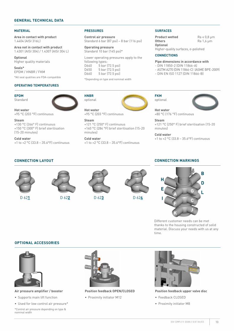
OPERATING TEMPERATURES
EPDMStandard
Hot water+95 °C (203 °F) continuous
Steam+130 °C (266° F) continuous+150 °C (300° F) brief sterilisation (15-20 minutes)
Cold water+1 to +2 °C (33.8 – 35.6°F) continuous
HNBRoptional
Hot water+95 °C (203 °F) continuous
Steam+121 °C (250° F) continuous+140 °C (284 °F) brief sterilisation (15-20 minutes)
Cold water+1 to +2 °C (33.8 – 35.6°F) continuous
FKMoptional
Hot water+80 °C (176 °F) continuous
Steam+121 °C (250° F) brief sterilisation (15-20 minutes)
Cold water+1 to +2 °C (33.8 – 35.6°F) continuous
GENERAL TECHNICAL DATA
*All seal qualities are FDA-compatible
MATERIAL
Area in contact with product1.4404 (AISI 316L)
Area not in contact with product1.4301 (AISI 304) / 1.4307 (AISI 304 L)
OptionalHigher quality materials
Seals*EPDM / HNBR / FKM
PRESSURES
Control air pressureStandard 6 bar (87 psi) – 8 bar (116 psi)
Operating pressureStandard 10 bar (145 psi)*
Lower operating pressures apply to the following types:D640 5 bar (72.5 psi)D650 5 bar (72.5 psi) D660 5 bar (72.5 psi)*Depending on type and nominal width
CONNECTION LAYOUT
D 621 D 622 D 623 D 624
CONNECTION MARKINGS
Different customer needs can be met thanks to the housing constructed of solid material. Discuss your needs with us at any time.
Air pressure amplifier / booster
• Supports main lift function
• Used for low control air pressure**Control air pressure depending on type & nominal width
Position feedback OPEN/CLOSED
• Proximity initiator M12
Position feedback upper valve disc
• Feedback CLOSED
• Proximity initiator M8
OPTIONAL ACCESSORIES
A
F
K
G
C
J
H
E
I
B
D
L
SURFACES
Product wetted Ra ≤ 0,8 μm Others Ra 1,6 μm Optional Higher-quality surfaces, e-polished
CONNECTIONS
Pipe dimensions in accordance with - DIN 11850-2 (DIN 11866-A) - ASTM A270 (DIN 11866-C) (ASME BPE-2009) - DIN EN ISO 1127 (DIN 11866-B)
14
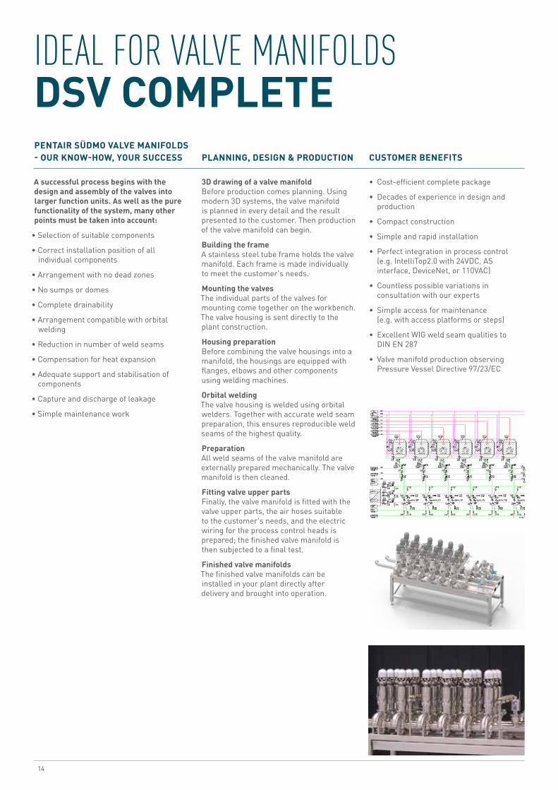
IDEAL FOR VALVE MANIFOLDS DSV COMPLETE
A successful process begins with the design and assembly of the valves into larger function units. As well as the pure functionality of the system, many other points must be taken into account:
• Selection of suitable components
• Correct installation position of all individual components
• Arrangement with no dead zones
• No sumps or domes
• Complete drainability
• Arrangement compatible with orbital welding
• Reduction in number of weld seams
• Compensation for heat expansion
• Adequate support and stabilisation of components
• Capture and discharge of leakage
• Simple maintenance work
PENTAIR SÜDMO VALVE MANIFOLDS - OUR KNOW-HOW, YOUR SUCCESS
3D drawing of a valve manifoldBefore production comes planning. Using modern 3D systems, the valve manifold is planned in every detail and the result presented to the customer. Then production of the valve manifold can begin.
Building the frameA stainless steel tube frame holds the valve manifold. Each frame is made individually to meet the customer's needs.
Mounting the valvesThe individual parts of the valves for mounting come together on the workbench. The valve housing is sent directly to the plant construction.
Housing preparationBefore combining the valve housings into a manifold, the housings are equipped with flanges, elbows and other components using welding machines.
Orbital weldingThe valve housing is welded using orbital welders. Together with accurate weld seam preparation, this ensures reproducible weld seams of the highest quality.
PreparationAll weld seams of the valve manifold are externally prepared mechanically. The valve manifold is then cleaned.
Fitting valve upper partsFinally, the valve manifold is fitted with the valve upper parts, the air hoses suitable to the customer's needs, and the electric wiring for the process control heads is prepared; the finished valve manifold is then subjected to a final test.
Finished valve manifoldsThe finished valve manifolds can be installed in your plant directly after delivery and brought into operation.
PLANNING, DESIGN & PRODUCTION
CUSTOMER BENEFITS
• Cost-efficient complete package
• Decades of experience in design and production
• Compact construction
• Simple and rapid installation
• Perfect integration in process control (e.g. IntelliTop2.0 with 24VDC, AS interface, DeviceNet, or 110VAC)
• Countless possible variations in consultation with our experts
• Simple access for maintenance (e.g. with access platforms or steps)
• Excellent WIG weld seam qualities to DIN EN 287
• Valve manifold production observing Pressure Vessel Directive 97/23/EC

15D S V C O M P L E T E D O U B L E S E A T V A LV E S
INTELLIGENT CONTROL TECHNOLOGY INTELLITOP® 2.0
The innovative control unit offers the customer countless possibilities for automation of process systems, and hence considerable potential for increasing efficiency.The IntelliTop 2.0 was awarded the IF Product Design Award 2010 for its perfect combination of function and aesthetics.
The IntelliTop 2.0 control unit from Pentair Südmo combines control and monitoring of process valves in one unit. The decentral arrangement of the control heads on the process valves allows a reduction in hose and cable lengths and leads to a clear system structure.
The heart of the IntelliTop 2.0 is the travel measurement system to detect up to three switch positions of the process valve. Great emphasis has been placed on simple programming by means of three Teach-In keys. This guarantees rapid and process-reliable commissioning. At the same time, the closed travel measurement system serves as a protective tube which prevents risk of injury when the control head is open, and protects the internal technology on installation of the head.
Communication 24 V DC AS interface DeviceNet 110 V AC
Travel Measurement SystemLift range 85 mmFeedback 3 positions, adjustable,
connection for external signal
Magnetic valvesNumber 0-3 pcsFlow 200 l/minChoke function Intake and extraction air
separate Electrical connections24 VDC Cable passageAS interface Cable with 4-pin M12x1
plugDeviceNet Cable with 5-pin M12x1
plug110 V AC Cable passage Pneumatic connectionsPush-fit hose connection Ø 6 mm (optional 5/16“)Push-fit hose connection Ø 8 mm (1/4“) Other data LED status display green, yellow, redProtection classes IP65 and IP 67 combined IP 69KEx-zone Zone 2/22
• Process-reliable system monitoring, simple, intuitive and rapid implementation
• Process valve switch times can be set using integral supply and extraction air chokes
• All-round LED display for visual status monitoring (colour allocation can be configured)
• Simplified valve maintenance thanks to maintenance function which can be activated externally
• Plant-specific adaptations via integrated microcontroller
• Integrated microcontroller supplies additional information
• Short air hose and cable routes, clear structure of process plant
• Simple, rapid fault analysis and repair, so reduction in plant downtimes
• Compact construction and optimum compatibility with Pentair Südmo process valves
• Scanning of all valve positions possible in double-seat valve
BENEFITS
TECHNICAL DATA BENEFITS

PENTAIR SÜDMO GMBHINDUSTRIESTRASSE 7, 73469 RIESBÜRG, GERMANY WWW.SUEDMO.DE
All Pentair trademarks and logos are owned by Pentair. All other brand or product names are trademarks or registered marks of their respective owners. Because we are continuously improving our products and services, Pentair reserves the right to change specifications without prior notice.Pentair is an equal opportunity employer.ID-No.: 2222351 - DSV Brochure E-2/16 © 2016 Pentair - All Rights Reserved.