scsi bus a connector pin out - baylor ecscs.ecs.baylor.edu/~maurer/csi5338/scsi handout.pdfscsi bus...
TRANSCRIPT

SCSI Bus A Connector Pin Out
Single -Ended Data Pinout
The "A" cable is used with SCSI-1, SCSI-2, or SCSI-3 to provide "FAST" SCSI with an 8 bit [Parallel] data bus. Refer here for the main SCSI Bus page. With SCSI-2 the "A" may be used alone or with the "B" cable to provide "WIDE" SCSI allowing a 16 or 32 bit data bus. The pin out for the 'A' Single -ended data cable is listed below. The differential pinout for the A Cable is shown on the Differential A Cable page.
The A cable has 50 conductors and provides an 8 bit data bus. The interface is Single-ended (unbalanced) with a cable length at 6 meters. SCSI-I used a Centronics 50 pin connector, 0.10 inch spacing, with 0.05 inch ribbon cable. While SCSI-II provided 8 bit data over a Micro D 50 pin, high density (50 mil). The 'A' cable impedance is between 90 and 140 ohms. The minimum conductor size is 28 AWG solid or stranded. For Connector and Cable Assembly manufacturers refer to the main SCSI page. With the advent of SCSI-4 in 2002, and then SCSI-5 in 2003, the 'A' cable is obsolete and should not be used for new designs. Also refer to the main Connector manufacturers page, Cable manufacturers page, and Cable Assembly manufacturers
Scsi terminator Scsi terminator, adapters and info from SCSI professionals
SCSI Cables & Connectors Factory direct cabling & supplies Same day shipping. Free catalog!
Ads by Goooooogle Advertise on this site
SCSI A Cable PinOut
Pin # Pin Function Pin # Pin Function1 Ground 26 D0-2 Ground 27 D1-3 Ground 28 D2-4 Ground 29 D3-5 Ground 30 D4-6 Ground 31 D5-7 Ground 32 D6-8 Ground 33 D7-9 Ground 34 DPARTY-10 Ground 35 Ground11 Ground 36 Ground12 Reserved 37 Reserved13 Open 38 TRMPWR14 Reserved 39 Reserved15 Ground 40 Ground16 Ground 41 ATN-17 Ground 42 Ground18 Ground 43 BSY-
Page 1 of 2SCSI Bus A Single-Ended Connector Pin Out and Signal Names, Pinout Information
3/2/2006http://www.interfacebus.com/Design_SCSI_A_Connector.html

The "B" Single-Ended cable pinout is listed on the SCSI Bus 'B' connector page. On SCSI-3, the "A" cable may be used for an 8 bit data bus. However the new "P" cable is used to provide a 16 bit data path (wide SCSI). To allow 32 bits of data the "P" cable is combined with another new cable called "Q" (wide SCSI). The "Q" cable pin out is listed on the SCSI Bus 'Q' Single -Ended connector or SCSI Bus 'Q' Differential connector page. The pin-out for the 'P' cable is listed on the SCSI Bus 'P' connector page.
Back to the main SCSI Interface Bus page The SCSI parallel bus width is either 8 bits or 16 bits [Wide bus]. Also the bus may be either Single ended or Differential; however the two are mutually exclusive SCSI is a chained parallel bus, cables start at the Host and run from device to device in a chain. SCSI may be used for asynchronous and synchronous transfers; Asynchronous transfers using Start and Stop bits and synchronous transfers using system timing (Hand-Shaking). The data bus also carries one parity bit.
Design Key words for this page: SCSI Physical Interface, Bus, Small Computer Systems Interface, SCSI Pin outs, SCSI PinOut, Pin Out, Signal/Differential Pin-outs, Pin Outs, A Connector, Signal Names, row, Pin Descriptions, Peripheral Computer Hard Drive Data Bus, Parallel data bus, Description, SCSI-1, SCSI-2, SCSI-3, Parallel SCSI, Direct Attached Storage [DAS], Networked Attached Storage [NAS], Storage Area Network [SAN]
Last Modified 1/28/06
Copyright © 1998 - 2006 All rights reserved Leroy Davis
19 Ground 44 ACK-20 Ground 45 RST-21 Ground 46 MSG-22 Ground 47 SEL-23 Ground 48 C/D-24 Ground 49 REG-25 Ground 50 I/O-
Lvd Scsi Cable Shop for Cables and Connectors! Find, Compare and Buy
SCSI Adapters Huge Selection of SCSI Adapters Our prices are very aggressive
Ads by Goooooogle Advertise on this site
Home
Distributors Components Equipment Software Standards Buses Design Reference
Page 2 of 2SCSI Bus A Single-Ended Connector Pin Out and Signal Names, Pinout Information
3/2/2006http://www.interfacebus.com/Design_SCSI_A_Connector.html

SCSI Bus A Connector Pin-Out
Differential Data
The "A" cable is used with SCSI-1, SCSI-2, or SCSI-3 to provide "FAST" SCSI with an 8 bit [Parallel] data bus. With SCSI-2 the "A" may be used alone or with the "B" cable to provide "WIDE" SCSI allowing a 16 or 32 bit data bus. The pin-out for the 'A' Single-ended data cable is listed below. The Single-ended pinout for the A Cable is shown on the Single -ended A Cable page. The A cable has 50 conductors and provides an 8 bit data bus. The interface is Differential (Twisted-pair) with a cable length at 25 meters maximum. A 1 foot minimum length cable shall be used between devices. SCSI-I used a Centronics 50 pin connector, 0.10 inch spacing, with 0.05 inch ribbon cable. While SCSI-II provided 8 bit data over a Micro D 50 pin, high density (50 mil). The 'A' cable impedance is between 90 and 140 ohms. The minimum conductor size is 28 AWG solid or stranded. For Connector and Cable Assembly manufacturers refer to the main SCSI page. Or refer to the main Connector manufacturers page, Cable manufacturers page, and Cable Assembly manufacturers
Ads by Google Parallel Cable PCI-X Parallel 64 Bit Printer RS232 9 Pin SCSI A Cable PinOut
Pin # Pin Function Pin # Pin Function1 Ground 26 Ground2 D0+ 27 D0-3 D1+ 28 D1-4 D2+ 29 D2-5 D3+ 30 D3-6 D4+ 31 D4-7 D5+ 32 D5-8 D6+ 33 D6-9 D7+ 34 D7-10 DPARTY+ 35 DPARTY-11 Ground 36 Ground12 Reserved 37 Reserved13 Open 38 TRMPWR14 Reserved 39 Reserved15 ATN+ 40 ATN-16 Ground 41 Ground17 BSY+ 42 BSY-18 ACK+ 43 ACK-19 RST+ 44 RST-20 MSG+ 45 MSG-21 SEL+ 46 SEL-22 C/D+ 47 C/D-23 REG+ 48 REG-
Page 1 of 2SCSI Bus A Differential Connector Pin Out and Signal Names, A Cable Pinout Information
3/2/2006http://www.interfacebus.com/SCSI_Differential_A_Cable_Pinout.html

The "B" Single-Ended cable pinout is listed on the SCSI Bus 'B' connector page. On SCSI-3, the "A" cable may be used for an 8 bit data bus. However the new "P" cable is used to provide a 16 bit data path (wide SCSI). To allow 32 bits of data the "P" cable is combined with another new cable called "Q" (wide SCSI). The "Q" cable pin-out is listed on the SCSI Bus 'Q' Single-Ended connector or SCSI Bus 'Q' Differential connector page. The pin-out for the 'P' cable is listed on the SCSI Bus 'P' connector page.
Back to the main SCSI Interface Bus page The SCSI [parallel] bus width is either 8 bits or 16 bits [Wide bus]. Also the bus may be either Single ended or Differential; however the two are mutually exclusive SCSI is a chained parallel bus, cables start at the Host and run from device to device in a chain. SCSI may be used for asynchronous and synchronous transfers; Asynchronous transfers using Start and Stop bits and synchronous transfers using system timing (Hand-Shaking). The data bus also carries one parity bit.
Design Key words for this page: SCSI Physical Interface, Bus, Small Computer Systems Interface, SCSI Pinouts, PinOut, Pin Out, Signal/Differential Pin-outs, Pin Outs, A Connector, Signal Names, row, Pin Descriptions, Peripheral Computer Hard Drive Data Bus, Parallel data bus, Description, Parallel SCSI, Direct Attached Storage [DAS], Networked Attached Storage [NAS], Storage Area Network [SAN]
Last Modified 12/25/05
Copyright © 1998 - 2006 All rights reserved Leroy Davis
24 I/O+ 49 I/0-25 Ground 50 Ground
Cable Test Made Easy Test Res, Caps, Diodes, IR/DWV Free Demo of Cable Tester
IEEE1284 Cable start $3.3 Bidirectional ieee cable A,B,C type we all have
Ads by Goooooogle Advertise on this site
Custom Cable Assemblies ISO 9001:2000, RoHS compliant In-house Engineering, EE & ME
Cables, Connectors & More Factory direct cabling & supplies Same day shipping. Free catalog!
IEEE1284 Cable start $3.3 Bidirectional ieee cable A,B,C type we all have
Custom molded cablesCustom overmolded assemblies Medical, OEMs, Custom, Molded
Ads by Goooooogle Advertise on this site
Home
Distributors Components Equipment Software Standards Buses Design Reference
Page 2 of 2SCSI Bus A Differential Connector Pin Out and Signal Names, A Cable Pinout Information
3/2/2006http://www.interfacebus.com/SCSI_Differential_A_Cable_Pinout.html

6 Logical characteristics 6.1 SCSI bus phases
The SCSI architecture includes eight distinct phases:
l a) BUS FREE phase l b) ARBITRATION phase l c) SELECTION phase l d) RESELECTION phase l e) COMMAND phase l f) DATA phase l g) STATUS phase l h) MESSAGE phase
Phases e)-h) are collectively termed the information transfer phases.
The SCSI bus can never be in more than one phase at any given time. In the following descriptions, signals that are not mentioned shall not be asserted.
6.1.1 BUS FREE phase
The BUS FREE phase indicates that there is no current I/O process and that the SCSI bus is available for a connection.
SCSI devices shall detect the BUS FREE phase after the SEL and BSY signals are both false for at least a bus settle delay.
SCSI devices shall release all SCSI bus signals within a bus clear delay after the BSY and SEL signals become continuously false for a bus settle delay. If an SCSI device requires more than a bus settle delay to detect the BUS FREE phase then it shall release all SCSI bus signals within a bus clear delay minus the excess time to detect the BUS FREE phase. The total time to clear the SCSI bus shall not exceed a bus settle delay plus a bus clear delay.
During normal operation the BUS FREE phase is entered when a target releases the BSY signal. However, the BUS FREE phase may be entered following the release of the SEL signal after a SELECTION or RESELECTION phase time-out.
Initiators normally do not expect BUS FREE phase to begin because of the target's release of the BSY signal except after one of the following occurrences:
l a) after a reset condition is detected; l b) after an ABORT message is successfully received by a target; l c) after a BUS DEVICE RESET message is successfully received by a target; l d) after a DISCONNECT message is successfully transmitted from a target (see 6.6.6);
Page 1 of 30SCSI-2 Spec - Logical characteristics
3/2/2006http://www.danbbs.dk/~dino/SCSI/SCSI2-06.html

l e) after a COMMAND COMPLETE message is successfully transmitted from a target (see 6.6.5); l f) after a RELEASE RECOVERY message is successfully received by a target; l g) after an ABORT TAG message is successfully received by a target; l h) after a CLEAR QUEUE message is successfully received by a target.
If an initiator detects the release of the BSY signal by the target at any other time, the target is indicating an error condition to the initiator. The target may perform this transition to the BUS FREE phase independent of the state of the ATN signal. The initiator shall manage this condition as an unsuccessful I/O process termination. The target terminates the I/O process by clearing all pending data and status information for the affected nexus. The target may optionally prepare sense data that may be retrieved by a REQUEST SENSE command.
6.1.2 ARBITRATION phase
The ARBITRATION phase allows one SCSI device to gain control of the SCSI bus so that it can initiate or resume an I/O process.
The procedure for an SCSI device to obtain control of the SCSI bus is as follows:
l a) The SCSI device shall first wait for the BUS FREE phase to occur. The BUS FREE phase is detected whenever both the BSY and SEL signals are simultaneously and continuously false for a minimum of a bus settle delay.
NOTE 16 This bus settle delay is necessary because a transmission line phenomenon known as a wired-OR glitch may cause the BSY signal to briefly appear false, even though it is being driven true.
l b) The SCSI device shall wait a minimum of a bus free delay after detection of the BUS FREE phase (i.e. after the BSY and SEL signals are both false for a bus settle delay) before driving any signal.
l c) Following the bus free delay in step (b), the SCSI device may arbitrate for the SCSI bus by asserting both the BSY signal and its own SCSI ID, however the SCSI device shall not arbitrate (i.e. assert the BSY signal and its SCSI ID) if more than a bus set delay has passed since the BUS FREE phase was last observed.
NOTE 17 There is no maximum delay before asserting the BSY signal and the SCSI ID following the bus free delay in step (b) as long as the bus remains in the BUS FREE phase. However, SCSI devices that delay longer than a bus settle delay plus a bus set delay from the time when the BSY and SEL signals first become false may fail to participate in arbitration when competing with faster SCSI devices.
l d) After waiting at least an arbitration delay (measured from its assertion of the BSY signal) the SCSI device shall examine the DATA BUS. If a higher priority SCSI ID bit is true on the DATA BUS (DB(7) is the highest), then the SCSI device has lost the arbitration and the SCSI device may release its signals and return to step (a). If no higher priority SCSI ID bit is true on the DATA BUS, then the SCSI device has won the arbitration and it shall assert the SEL signal. Any SCSI device other than the winner has lost the arbitration and shall release the BSY signal and its SCSI ID bit within a bus clear delay after the SEL signal becomes true. An SCSI device that loses arbitration may return to step (a).
Page 2 of 30SCSI-2 Spec - Logical characteristics
3/2/2006http://www.danbbs.dk/~dino/SCSI/SCSI2-06.html

NOTES 18 Step d) above requires that any device complete the arbitration phase to the point of SEL being asserted if it begins the arbitration phase as stated in step c). This precludes the possibility of the bus being hung. 19 It is recommended that new implementations wait for the SEL signal to become true before releasing the BSY signal and SCSI ID bit when arbitration is lost.
e) The SCSI device that wins arbitration shall wait at least a bus clear delay plus a bus settle delay after asserting the SEL signal before changing any signals.
NOTE 20 The SCSI ID bit is a single bit on the DATA BUS that corresponds to the SCSI device's unique SCSI address. All other DATA BUS bits shall be released by the SCSI device. Parity is not valid during the ARBITRATION phase. During the ARBITRATION phase, DB(P) may be released or asserted, but shall not be actively driven false.
6.1.3 SELECTION phase
The SELECTION phase allows an initiator to select a target for the purpose of initiating some target function (e.g., READ or WRITE command). During the SELECTION phase the I/O signal is negated so that this phase can be distinguished from the RESELECTION phase.
The SCSI device that won the arbitration has both the BSY and SEL signals asserted and has delayed at least a bus clear delay plus a bus settle delay before ending the ARBITRATION phase. The SCSI device that won the arbitration becomes an initiator by not asserting the I/O signal.
The initiator shall set the DATA BUS to a value that is the OR of its SCSI ID bit and the target's SCSI ID bit and it shall assert the ATN signal (indicating that a MESSAGE OUT phase is to follow the SELECTION phase). The initiator shall then wait at least two deskew delays and release the BSY signal. The initiator shall then wait at least a bus settle delay before looking for a response from the target.
The target shall determine that it is selected when the SEL signal and its SCSI ID bit are true and the BSY and I/O signals are false for at least a bus settle delay. The selected target may examine the DATA BUS in order to determine the SCSI ID of the selecting initiator. The selected target shall then assert the BSY signal within a selection abort time of its most recent detection of being selected; this is required for correct operation of the selection time-out procedure.
The target shall not respond to a selection if bad parity is detected. Also, if more than two SCSI ID bits are on the DATA BUS, the target shall not respond to selection.
NOTE 21 Although an SCSI-2 initiator may not use the single initiator option or the selection without asserting ATN option of SCSI-1, an SCSI-2 target may elect to support these options for compatibility with SCSI -1 initiators. When doing so the SCSI-2 target responds as described in the SCSI-1 standard.
No less than two deskew delays after the initiator detects the BSY signal is true, it shall release the SEL signal and may change the DATA BUS. The target shall wait until the SEL signal is false before asserting the REQ signal to enter an information transfer phase.
6.1.3.1 SELECTION time-out procedure
Page 3 of 30SCSI-2 Spec - Logical characteristics
3/2/2006http://www.danbbs.dk/~dino/SCSI/SCSI2-06.html
Two optional selection time-out procedures are specified for clearing the SCSI bus if the initiator waits a minimum of a selection time-out delay and there has been no BSY signal response from the target:
l a) Optionally, the initiator shall assert the RST signal (see 6.2.2); l b) Optionally, the initiator shall continue asserting the SEL and ATN signals and shall release the
DATA BUS. If the initiator has not detected the BSY signal to be true after at least a selection abort time plus two deskew delays, the initiator shall release the SEL and ATN signals allowing the SCSI bus to go to the BUS FREE phase. SCSI devices shall ensure that when responding to selection that the selection was still valid within a selection abort time of their assertion of the BSY signal. Failure to comply with this requirement could result in an improper selection (two targets connected to the same initiator, wrong target connected to an initiator, or a target connected to no initiator).
6.1.4 RESELECTION phase
RESELECTION is an optional phase that allows a target to reconnect to an initiator for the purpose of continuing some operation that was previously started by the initiator but was suspended by the target, (i.e. the target disconnected by allowing a BUS FREE phase to occur before the operation was complete).
6.1.4.1 RESELECTION
Upon completing the ARBITRATION phase, the winning SCSI device has both the BSY and SEL signals asserted and has delayed at least a bus clear delay plus a bus settle delay. The winning SCSI device becomes a target by asserting the I/O signal. The winning SCSI device shall also set the DATA BUS to a value that is the logical OR of its SCSI ID bit and the initiator's SCSI ID bit. The target shall wait at least two deskew delays and release the BSY signal. The target shall then wait at least a bus settle delay before looking for a response from the initiator.
The initiator shall determine that it is reselected when the SEL and I/O signals and its SCSI ID bit are true and the BSY signal is false for at least a bus settle delay. The reselected initiator may examine the DATA BUS in order to determine the SCSI ID of the reselecting target. The reselected initiator shall then assert the BSY signal within a selection abort time of its most recent detection of being reselected; this is required for correct operation of the time-out procedure. The initiator shall not respond to a RESELECTION phase if bad parity is detected. Also, the initiator shall not respond to a RESELECTION phase if other than two SCSI ID bits are on the DATA BUS.
After the target detects the BSY signal is true, it shall also assert the BSY signal and wait at least two deskew delays and then release the SEL signal. The target may then change the I/O signal and the DATA BUS. After the reselected initiator detects the SEL signal is false, it shall release the BSY signal. The target shall continue asserting the BSY signal until it relinquishes the SCSI bus.
NOTE 22 When the target is asserting the BSY signal, a transmission line phenomenon known as a wired-OR glitch may cause the BSY signal to appear false for up to a round-trip propagation delay following the release of the BSY signal by the initiator. This is the reason why the BUS FREE phase is recognized only after both the BSY and SEL signals are continuously false for a minimum of a bus settle delay. Cables longer than 25 m should not be used even if the chosen driver, receiver, and cable provide adequate noise margins, because they increase the duration of the glitch and could cause SCSI devices to inadvertently detect the BUS FREE phase.
Page 4 of 30SCSI-2 Spec - Logical characteristics
3/2/2006http://www.danbbs.dk/~dino/SCSI/SCSI2-06.html

6.1.4.2 RESELECTION time-out procedure
Two optional RESELECTION time-out procedures are specified for clearing the SCSI bus during a RESELECTION phase if the target waits a minimum of a selection time-out delay and there has been no BSY signal response from the initiator:
l a) Optionally, the target shall assert the RST signal (see 6.2.2); l b) Optionally, the target shall continue asserting the SEL and I/O signals and shall release all
DATA BUS signals. If the target has not detected the BSY signal to be true after at least a selection abort time plus two deskew delays, the target shall release the SEL and I/O signals allowing the SCSI bus to go to the BUS FREE phase. SCSI devices that respond to the RESELECTION phase shall ensure that the reselection was still valid within a selection abort time of their assertion of the BSY signal. Failure to comply with this requirement could result in an improper reselection (two initiators connected to the same target or the wrong initiator connected to a target).
6.1.5 Information transfer phases
NOTE 23 The COMMAND, DATA, STATUS, and MESSAGE phases are all grouped together as the information transfer phases because they are all used to transfer data or control information via the DATA BUS. The actual content of the information is beyond the scope of this section.
The C/D, I/O, and MSG signals are used to distinguish between the different information transfer phases (see table 8). The target drives these three signals and therefore controls all changes from one phase to another. The initiator can request a MESSAGE OUT phase by asserting the ATN signal, while the target can cause the BUS FREE phase by releasing the MSG, C/D, I/O, and BSY signals.
The information transfer phases use one or more REQ/ACK handshakes to control the information transfer. Each REQ/ACK handshake allows the transfer of one byte of information. During the information transfer phases the BSY signal shall remain true and the SEL signal shall remain false. Additionally, during the information transfer phases, the target shall continuously envelope the REQ/ACK handshake(s) with the C/D, I/O, and MSG signals in such a manner that these control signals are valid for a bus settle delay before the assertion of the REQ signal of the first handshake and remain valid until after the negation of the ACK signal at the end of the handshake of the last transfer of the phase.
NOTES 24 After the negation of the ACK signal of the last transfer of the phase, the target may prepare for a new phase by asserting or negating the C/D, I/O, and MSG signals. These signals may be changed together or individually. They may be changed in any order and may be changed more than once. It is desirable that each line change only once. A new phase does not begin until the REQ signal is asserted for the first byte of the new phase. 25 A phase is defined as ending when the C/D, I/O, or MSG signals change after the negation of the ACK signal. The time between the end of a phase and the assertion of the REQ signal beginning a new phase is undefined. An initiator is allowed to anticipate a new phase based on the previous phase, the expected new phase, and early information provided by changes in the C/D, I/O, and MSG signals. However, the anticipated phase is not valid until the REQ signal is asserted at the beginning of the next phase.
Page 5 of 30SCSI-2 Spec - Logical characteristics
3/2/2006http://www.danbbs.dk/~dino/SCSI/SCSI2-06.html

Table 8 - Information transfer phases
+=============-===============-==================================-============+ | Signal | Phase name | Direction of transfer | Comment | |-------------| | | | | MSG|C/D|I/O | | | | |----+---+----+---------------+----------------------------------+------------| | 0 | 0 | 0 | DATA OUT | Initiator to target \ | Data | | 0 | 0 | 1 | DATA IN | Initiator from target / | phase | | 0 | 1 | 0 | COMMAND | Initiator to target | | | 0 | 1 | 1 | STATUS | Initiator from target | | | 1 | 0 | 0 | * | | | | 1 | 0 | 1 | * | | | | 1 | 1 | 0 | MESSAGE OUT | Initiator to target \ | Message | | 1 | 1 | 1 | MESSAGE IN | Initiator from target / | phase | |-----------------------------------------------------------------------------| | Key: 0 = False, 1 = True, * = Reserved for future standardization | +=============================================================================+
6.1.5.1 Asynchronous information transfer
The target shall control the direction of information transfer by means of the I/O signal. When the I/O signal is true, information shall be transferred from the target to the initiator. When the I/O signal is false, information shall be transferred from the initiator to the target.
If the I/O signal is true (transfer to the initiator), the target shall first drive the DB(7-0,P) signals to their desired values, delay at least one deskew delay plus a cable skew delay, then assert the REQ signal. The DB(7-0,P) signals shall remain valid until the ACK signal is true at the target. The initiator shall read the DB(7-0,P) signals after the REQ signal is true, then indicate its acceptance of the data by asserting the ACK signal. When the ACK signal becomes true at the target, the target may change or release the DB(7-0,P) signals and shall negate the REQ signal. After the REQ signal is false the initiator shall then negate the ACK signal. After the ACK signal is false the target may continue the transfer by driving the DB(7-0,P) signals and asserting the REQ signal, as described above.
If the I/O signal is false (transfer to the target) the target shall request information by asserting the REQ signal. The initiator shall drive the DB(7-0,P) signals to their desired values, delay at least one deskew delay plus a cable skew delay and assert the ACK signal. The initiator shall continue to drive the DB(7-0,P) signals until the REQ signal is false. When the ACK signal becomes true at the target, the target shall read the DB(7-0,P), signals then negate the REQ signal. When the REQ signal becomes false at the initiator, the initiator may change or release the DB(7-0,P) signals and shall negate the ACK signal. After the ACK signal is false the target may continue the transfer by asserting the REQ signal, as described above.
6.1.5.2 Synchronous data transfer
Synchronous data transfer is optional and is only used in data phases. It shall be used in a data phase if a synchronous data transfer agreement has been established (see 6.6.21). The agreement specifies the REQ/ACK offset and the minimum transfer period.
The REQ/ACK offset specifies the maximum number of REQ pulses that can be sent by the target in advance of the number of ACK pulses received from the initiator, establishing a pacing mechanism. If the number of REQ pulses exceeds the number of ACK pulses by the REQ/ACK offset, the target shall not assert the REQ signal until after the leading edge of the next ACK pulse is received. For successful
Page 6 of 30SCSI-2 Spec - Logical characteristics
3/2/2006http://www.danbbs.dk/~dino/SCSI/SCSI2-06.html
completion of the data phase is that the number of ACK and REQ pulses shall be equal.
The target shall assert the REQ signal for a minimum of an assertion period. The target shall then wait at least the greater of a transfer period from the last transition of the REQ signal to true or a minimum of a negation period from the last transition of the REQ signal to false before again asserting the REQ signal.
The initiator shall send one pulse on the ACK signal for each REQ pulse received. The ACK signal may be asserted as soon as the leading edge of the corresponding REQ pulse has been received. The initiator shall assert the ACK signal for a minimum of an assertion period. The initiator shall wait at least the greater of a transfer period from the last transition of the ACK signal to true or for a minimum of a negation period from the last transition of the ACK signal to false before asserting the ACK signal.
If the I/O signal is true (transfer to the initiator), the target shall first drive the DB(7-0,P) signals to their desired values, wait at least one deskew delay plus one cable skew delay, then assert the REQ signals. The DB(7-0,P) signals shall be held valid for a minimum of one deskew delay plus one cable skew delay plus one hold time after the assertion of the REQ signal. The target shall assert the REQ signal for a minimum of an assertion period. The target may then negate the REQ signal and change or release the DB(7-0,P) signals. The initiator shall read the value on the DB(7-0,P) signals within one hold time of the transition of the REQ signal to true. The initiator shall then respond with an ACK pulse.
If the I/O signal is false (transfer to the target), the initiator shall transfer one byte for each REQ pulse received. After receiving the leading edge of a REQ pulse, the initiator shall first drive the DB(7-0,P) signals to their desired values, delay at least one deskew delay plus one cable skew delay, then assert the ACK signal. The initiator shall hold the DB(7-0,P) signals valid for at least one deskew delay plus one cable skew delay plus one hold time after the assertion of the ACK signal. The initiator shall assert the ACK signal for a minimum of an assertion period. The initiator may then negate the ACK signal and may change or release the DB(7-0,P) signals. The target shall read the value of the DB(7-0,P) signals within one hold time of the transition of the ACK signal to true.
NOTE 26 The description in SCSI -1 allowed some implementors to presume that the leading edge of the first REQ pulse beyond the REQ/ACK offset agreement would not occur until after the trailing edge of the last ACK pulse within the agreement. Devices implemented with this understanding may be subject to data destruction when in synchronous data transfer mode with devices that issue the leading edge of the next REQ pulse, at the boundary of the agreement, as soon as the leading edge of the last ACK pulse within the agreement is received. Implementors using devices of the former type in initiator designs may insure data integrity by restricting the synchronous offset agreement to values smaller than the maximum nominally offered by their device.
6.1.5.3 Wide data transfer
Wide data transfer is optional and may be used in the DATA phase only if a non-zero wide data transfer agreement is in effect (see WIDE DATA TRANSFER REQUEST message, 6.6.23). The messages determine the use of wide mode by both SCSI devices and establish a data path width to be used during the DATA phase.
Wide data transfers of 16- or 32-bits may be established. Targets and initiators that support 32-bit wide transfers should also support 16-bit wide transfers. All SCSI devices shall support 8-bit data transfers.
During 16-bit wide data transfers, the first logical data byte for each data phase shall be transferred
Page 7 of 30SCSI-2 Spec - Logical characteristics
3/2/2006http://www.danbbs.dk/~dino/SCSI/SCSI2-06.html

across the DB(7-0,P) signals on the A cable and the second logical data byte shall be transferred across the DB(15-8,P1) signals on the B cable. Subsequent pairs of data bytes are likewise transferred in parallel across the A and B cables (see figure 15).
NOTE 27 X3T9.2 is documenting an alternate 16-bit single-cable solution and an alternate 32-bit solution and expects to be able to remove the B cable definition in a future version of SCSI.
During 32-bit wide data transfers, the first logical data byte for each data phase shall be transferred across the DB(7-0,P) signals on the A cable and the second, third, and fourth logical data bytes shall be transferred across the DB(15-8,P1), DB(23-16,P2), and DB(31-24,P3) signals, respectively, on the B cable. Subsequent groups of four data bytes are likewise transferred in parallel across the A and B cables (see figure 15).
Figure 15 - Wide SCSI byte ordering
If the last data byte transferred does not fall on the DB(15-8,P1) signals for a 16-bit wide transfer or the DB(31-24,P3) signals for a 32-bit wide transfer, then the values of the remaining higher-numbered bits are undefined. However, parity bits for these undefined bytes shall be valid for whatever data is placed on the bus.
To ensure proper data integrity, certain sequence requirements shall be met between the REQ/ACK handshakes on the A cable and the REQB/ACKB handshakes on the B cable:
l a) The REQB and ACKB signals shall only be asserted during data phases while a nonzero wide data transfer agreement is in effect. These signals shall not be asserted during other phases.
l b) The same information transfer mode (asynchronous or synchronous) shall be used for both the A cable and the B cable. If synchronous data transfer mode is in effect, the same REQ/ACK offset and transfer period shall be used for both cables.
l c) The information transfer procedures defined in 6.1.5.1 and 6.1.5.2 for the A cable (the REQ, ACK, and DB(7-0,P) signals) shall also apply to the B cable (the REQB, ACKB, and DB(31-8,P1,P2,P3) signals). The only means available for a target to manage the timing relationship between the signals on the two cables is its management of the REQ and REQB signals. Similarly, the only means for the initiator to manage the timing between the two cables is its management of the ACK and ACKB signals.
l d) The target shall ensure that the number of REQ/ACK handshakes and the number of REQB/ACKB handshakes in a data phase are equal before it changes to another phase. The target shall not change the phase until the ACK and ACKB signals have both become false for the last REQ/ACK handshake and the last REQB/ACKB handshake.
NOTE 28 If any violations of these rules are detected by the target, the target may attempt to end the data phase and return CHECK CONDITION status. If it is impossible to correctly terminate the data phase, the target may abnormally terminate the I/O process by an unexpected disconnect. If any violations of these rules are detected by the initiator, the initiator may attempt to send an INITIATOR DETECTED ERROR message to the target. If the initiator is unable to terminate the I/O process normally, it may generate the reset
Page 8 of 30SCSI-2 Spec - Logical characteristics
3/2/2006http://www.danbbs.dk/~dino/SCSI/SCSI2-06.html
condition.
6.1.6 COMMAND phase
The COMMAND phase allows the target to request command information from the initiator.
The target shall assert the C/D signal and negate the I/O and MSG signals during the REQ/ACK handshake(s) of this phase.
6.1.7 Data phase
The data phase is a term that encompasses both the DATA IN phase and the DATA OUT phase.
6.1.7.1 DATA IN phase
The DATA IN phase allows the target to request that data be sent to the initiator from the target.
The target shall assert the I/O signal and negate the C/D and MSG signals during the REQ/ACK handshake(s) of this phase.
6.1.7.2 DATA OUT phase
The DATA OUT phase allows the target to request that data be sent from the initiator to the target.
The target shall negate the C/D, I/O, and MSG signals during the REQ/ACK handshake(s) of this phase.
6.1.8 STATUS phase
The STATUS phase allows the target to request that status information be sent from the target to the initiator.
The target shall assert the C/D and I/O signals and negate the MSG signal during the REQ/ACK handshake of this phase.
6.1.9 Message phase
The message phase is a term that references either a MESSAGE IN, or a MESSAGE OUT phase. Multiple messages may be sent during either phase. The first byte transferred in either of these phases shall be either a single-byte message or the first byte of a multiple-byte message. Multiple-byte messages shall be wholly contained within a single message phase.
6.1.9.1 MESSAGE IN phase
The MESSAGE IN phase allows the target to request that message(s) be sent to the initiator from the target.
The target shall assert the C/D, I/O, and MSG signals during the REQ/ACK handshake(s) of this phase.
6.1.9.2 MESSAGE OUT phase
Page 9 of 30SCSI-2 Spec - Logical characteristics
3/2/2006http://www.danbbs.dk/~dino/SCSI/SCSI2-06.html

The MESSAGE OUT phase allows the target to request that message(s) be sent from the initiator to the target. The target invokes this phase in response to the attention condition created by the initiator (see 6.2.1).
The target shall assert the C/D and MSG signals and negate the I/O signal during the REQ/ACK handshake(s) of this phase. The target shall handshake byte(s) in this phase until the ATN signal is negated, except when rejecting a message.
If the target detects one or more parity error(s) on the message byte(s) received, it may indicate its desire to retry the message(s) by asserting the REQ signal after detecting the ATN signal has gone false and prior to changing to any other phase. The initiator, upon detecting this condition, shall resend all of the previous message byte(s) in the same order as previously sent during this phase. When resending more than one message byte, the initiator shall assert the ATN signal at least two deskew delays prior to asserting the ACK signal on the first byte and shall maintain the ATN signal asserted until the last byte is sent as described in 6.2.1.
If the target does not retry the MESSAGE OUT phase or it exhausts its retry limit it may
l a) return CHECK CONDITION status and set the sense key to ABORTED COMMAND and the additional sense code to MESSAGE ERROR or;
l b) indicate an exception condition by performing an unexpected disconnect.
The target may act on messages as received as long as no parity error is detected and may ignore all remaining messages sent under one ATN condition after a parity error is detected. When a sequence of messages is resent by an initiator because of a target detected parity error, the target shall not act on any message which it acted on the first time received.
If the target receives all of the message byte(s) successfully (i.e. no parity errors), it shall indicate that it does not wish to retry by changing to any information transfer phase other than the MESSAGE OUT phase and transfer at least one byte. The target may also indicate that it has successfully received the message byte(s) by changing to the BUS FREE phase (e.g. ABORT or BUS DEVICE RESET messages).
6.1.10 Signal restrictions between phases
When the SCSI bus is between two information transfer phases, the following restrictions shall apply to the SCSI bus signals:
l a) The BSY, SEL, REQ, REQB, ACK and ACKB signals shall not change. l b) The C/D, I/O, MSG, and DATA BUS signals may change. When switching the DATA BUS
direction from out (initiator driving) to in (target driving), the target shall delay driving the DATA BUS by at least a data release delay plus a bus settle delay after asserting the I/O signal and the initiator shall release the DATA BUS no later than a data release delay after the transition of the I/O signal to true. When switching the DATA BUS direction from in (target driving) to out (initiator driving), the target shall release the DATA BUS no later than a deskew delay after negating the I/O signal.
l c) The ATN and RST signals may change as defined under the descriptions for the attention condition (see 6.2.1) and reset condition (see 6.2.2).
6.2 SCSI bus conditions
Page 10 of 30SCSI-2 Spec - Logical characteristics
3/2/2006http://www.danbbs.dk/~dino/SCSI/SCSI2-06.html

The SCSI bus has two asynchronous conditions; the attention condition and the reset condition. These conditions cause the SCSI device to perform certain actions and can alter the phase sequence.
Furthermore, SCSI devices may not all be powered-on at the same time. This standard does not address power sequencing issues. However, each SCSI device, as it is powered on, should perform appropriate internal reset operations and internal test operations. Following a power-on to selection time after power-on, SCSI targets should be able to respond with appropriate status and sense data to the TEST UNIT READY, INQUIRY, and REQUEST SENSE commands.
6.2.1 Attention condition
The attention condition allows an initiator to inform a target that the initiator has a message ready. The target may get this message by performing a MESSAGE OUT phase.
The initiator creates the attention condition by asserting ATN at any time except during the ARBITRATION or BUS FREE phases.
The initiator shall negate the ATN signal at least two deskew delays before asserting the ACK signal while transferring the last byte of the messages indicated with a Yes in table 10. If the target detects that the initiator failed to meet this requirement, then the target shall go to BUS FREE phase (see unexpected disconnect, 6.1.1).
The initiator shall assert the ATN signal at least two deskew delays before negating the ACK signal for the last byte transferred in a bus phase for the attention condition to be honoured before transition to a new bus phase. Asserting the ATN signal later might not be honoured until a later bus phase and then may not result in the expected action.
A target shall respond with MESSAGE OUT phase as follows:
l a) If the ATN signal becomes true during a COMMAND phase, the target shall enter MESSAGE OUT phase after transferring part or all of the command descriptor block bytes.
l b) If the ATN signal becomes true during a DATA phase, the target shall enter MESSAGE OUT phase at the target's earliest convenience (often, but not necessarily on a logical block boundary). The initiator shall continue REQ/ACK handshakes until it detects the phase change.
l c) If the ATN signal becomes true during a STATUS phase, the target shall enter MESSAGE OUT phase after the status byte has been acknowledged by the initiator.
l d) If the ATN signal becomes true during a MESSAGE IN phase, the target shall enter MESSAGE OUT phase before it sends another message. This permits a MESSAGE PARITY ERROR message from the initiator to be associated with the appropriate message.
l e) If the ATN signal becomes true during a SELECTION phase and before the initiator releases the BSY signal, the target shall enter MESSAGE OUT phase immediately after that SELECTION phase.
l f) If the ATN signal becomes true during a RESELECTION phase, the target shall enter MESSAGE OUT phase after the target has sent its IDENTIFY message for that RESELECTION phase.
NOTE 29 The initiator should only assert the ATN signal during a RESELECTION phase to transmit a BUS DEVICE RESET or DISCONNECT message. Other uses may result in ambiguities concerning the nexus.
Page 11 of 30SCSI-2 Spec - Logical characteristics
3/2/2006http://www.danbbs.dk/~dino/SCSI/SCSI2-06.html
The initiator shall keep the ATN signal asserted if more than one byte is to be transferred. The initiator may negate the ATN signal at any time except it shall not negate the ATN signal while the ACK signal is asserted during a MESSAGE OUT phase. Normally, the initiator negates the ATN signal while the REQ signal is true and the ACK signal is false during the last REQ/ACK handshake of the MESSAGE OUT phase.
6.2.2 Reset condition
The reset condition is used to immediately clear all SCSI devices from the bus. This condition shall take precedence over all other phases and conditions. Any SCSI device may create the reset condition by asserting the RST signal for a minimum of a reset hold time.
All SCSI devices shall release all SCSI bus signals (except the RST signal) within a bus clear delay of the transition of the RST signal to true. The BUS FREE phase always follows the reset condition.
The effect of the reset condition on I/O processes that have not completed, SCSI device reservations, and SCSI device operating modes is determined by whether the SCSI device has implemented the hard reset alternative or the soft reset alternative (one of which shall be implemented) as defined in 6.2.2.1 and 6.2.2.2. The hard and soft reset alternatives are mutually exclusive within a system. A facility for targets to report which reset alternative is implemented is provided in the SftRe bit of the INQUIRY data (see 8.2.5).
NOTE 30 Environmental conditions (e.g. static discharge) may generate brief glitches on the RST signal. It is recommended that SCSI devices not react to these glitches. The manner of rejecting glitches is vendor-specific. The bus clear delay following a RST signal transition to true is measured from the original transition of the RST signal, not from the time that the signal has been confirmed. This limits the time to confirm the RST signal to a maximum of a bus clear delay.
6.2.2.1 Hard reset alternative
SCSI devices that implement the hard reset alternative, upon detection of the reset condition, shall:
l a) clear all I/O processes including queued I/O processes. l b) release all SCSI device reservations. l c) return any SCSI device operating modes to their appropriate initial conditions, similar to those
conditions that would be found after a normal power-on reset. MODE SELECT conditions shall be restored to their last saved values if saved values have been established. MODE SELECT conditions for which no values have been saved shall be returned to their default values.
l d) unit attention condition shall be set (see 7.9).
It is recommended that following a reset to selection time after a hard reset condition ends, SCSI targets be able to respond with appropriate status and sense data to the TEST UNIT READY, INQUIRY, and REQUEST SENSE commands.
6.2.2.2 Soft reset alternative
SCSI devices that implement the soft reset alternative, upon detection of the reset condition, shall:
l a) Attempt to complete any I/O processes which have not completed and that were fully identified
Page 12 of 30SCSI-2 Spec - Logical characteristics
3/2/2006http://www.danbbs.dk/~dino/SCSI/SCSI2-06.html

l b) Preserve all SCSI device reservations l c) Preserve any SCSI device operating modes (MODE SELECT, PREVENT/ALLOW MEDIUM
REMOVAL commands, etc.) l d) Preserve all the information required to continue normal dispatching of I/O processes queued
prior to the reset condition.
The soft reset alternative allows an initiator to reset the SCSI bus with minimum disruption to the operation of other initiators in a multiple initiator system. To ensure proper operation the following conditions shall be met.
l a) An initiator shall not consider an I/O process to be fully identified until the IDENTIFY message (and queue tag message, if any) is sent to the target and the target responds by changing to any other information transfer phase and requests that at least one byte be transferred.
l b) A target shall consider an I/O process to be fully identified when it successfully receives the IDENTIFY message and any queue tag message and the initiator negates the ATN signal.
l c) If an initiator selects a logical unit for which there already is an active I/O process with the same queue tag (if any) for the same initiator, the target shall clear the original I/O process and perform the new I/O process.
l d) If a target reselects an initiator to continue an I/O process for which the initiator has no record, the initiator shall abort that I/O process by sending the ABORT or ABORT TAG message, depending on whether the reselecting I/O process is a tagged I/O process.
l e) An initiator shall consider an I/O process to be completed when it negates ACK for a successfully received COMMAND COMPLETE message.
l f) A target shall consider an I/O process to be completed when it detects the transition of ACK to false for the COMMAND COMPLETE message with the ATN signal false.
l g) An initiator shall not negate the ACK signal for the SAVE DATA POINTER message until it has actually saved the data pointer for the I/O process.
l h) A target shall consider the data pointer to be saved when it detects the transition of the ACK signal to false for the SAVE DATA POINTER message with the ATN signal false.
l i) If the reset condition occurs between the time that the target asserts the REQ signal for the SAVE DATA POINTER message and it detects the transition of the ACK signal to false, the target shall terminate the I/O process with CHECK CONDITION status. The target shall set the sense key to ABORTED COMMAND. This is necessary because the target cannot determine whether the data pointer has actually been saved.
NOTE 31 If the ATN signal is true in conditions f) or h), the target would normally switch to MESSAGE OUT phase and attempt to transfer a message byte. If the reset condition occurs before the target successfully receives the message byte, it may assume that the initiator has not successfully received the COMMAND COMPLETE message or the SAVE DATA POINTER message. In the case of COMMAND COMPLETE message, the target may reselect the initiator and attempt to send the COMMAND COMPLETE message again. In the case of the SAVE DATA POINTER message, the target may reselect the initiator and terminate the I/O process as described in condition i).
6.3 SCSI bus phase sequences
The order in which phases are used on the SCSI bus follows a prescribed sequence.
The reset condition can abort any phase and is always followed by the BUS FREE phase. Also any other phase can be followed by the BUS FREE phase but many such instances are error conditions (see 6.1.1).
Page 13 of 30SCSI-2 Spec - Logical characteristics
3/2/2006http://www.danbbs.dk/~dino/SCSI/SCSI2-06.html

The additional allowable sequences shall be as shown in Figure 16. The normal progression is from the BUS FREE phase to ARBITRATION, from ARBITRATION to SELECTION or RESELECTION, and from SELECTION or RESELECTION to one or more of the information transfer phases (COMMAND, DATA, STATUS, or MESSAGE). The final information transfer phase is normally the MESSAGE IN phase where a DISCONNECT, or COMMAND COMPLETE message is transferred, followed by the BUS FREE phase.
Figure 16 - Phase sequences
6.4 SCSI pointers
Consider the system shown in figure 17 in which an initiator and target communicate on the SCSI bus in order to execute an I/O process.
The SCSI architecture provides for a set of three pointers for each I/O process, called the saved pointers. The set of three pointers consist of one for the command, one for the data, and one for the status. When an I/O process becomes active, its three saved pointers are copied into the initiator's set of three current pointers. There is only one set of current pointers in each initiator. The current pointers point to the next command, data, or status byte to be transferred between the initiator's memory and the target. The saved and current pointers reside in the initiator.
The saved command pointer always points to the start of the command descriptor block (see 7.2) for the I/O process. The saved status pointer always points to the start of the status area for the I/O process. The saved data pointer points to the start of the data area until the target sends a SAVE DATA POINTER message (see 6.6.20) for the I/O process.
Figure 17 - Simplified SCSI system
In response to the SAVE DATA POINTER message, the initiator stores the value of the current data pointer into the saved data pointer for that I/O process. The target may restore the current pointers to the saved pointer values for the active I/O process by sending a RESTORE POINTERS message (see 6.6.19) to the initiator. The initiator then copies the set of saved pointers into the set of current pointers. Whenever a target disconnects from the bus, only the set of saved pointers are retained. The set of current pointers is restored from the set of saved pointers upon reconnection of the I/O process.
NOTE 32 Since the data pointer value may be modified by the target before the I/O process ends, it should not be used to test for actual transfer length because it is not reliable.
6.5 Message system description
Page 14 of 30SCSI-2 Spec - Logical characteristics
3/2/2006http://www.danbbs.dk/~dino/SCSI/SCSI2-06.html

The message system allows communication between an initiator and target for the purpose of interface management. A message may be one, two, or multiple bytes in length. One or more messages may be sent during a single MESSAGE phase, but a message may not be split between multiple MESSAGE phases. The initiator is required to end the MESSAGE OUT phase (by negating ATN) when it sends certain messages identified in table 10.
One-byte, two-byte, and extended message formats are defined. The first byte of the message determines the format as defined in table 9.
Table 9 - Message format
+=============-===============================================================+ | Value | Message format | |-------------+---------------------------------------------------------------| | 00h | One-byte message (COMMAND COMPLETE) | | 01h | Extended messages | | 02h - 1Fh | One-byte messages | | 20h - 2Fh | Two-byte messages | | 30h - 7Fh | Reserved | | 80h - FFh | One-byte message (IDENTIFY) | +=============================================================================+
One-byte messages consist of a single byte transferred during a MESSAGE phase. The value of the byte determines which message is to be performed as defined in table 10.
Table 10 - Message codes
+========-=========-===================================-=========-===============+ |Code | Support |Message Name |Direction| | | |---------| | | Negate ATN | | |Init|Targ| | |before last ACK| |--------+----+----+-----------------------------------+---------+---------------| |06h | O | M |ABORT | Out| Yes | |0Dh | O | O |ABORT TAG see note 1) | Out| Yes | |0Ch | O | M |BUS DEVICE RESET | Out| Yes | |0Eh | O | O |CLEAR QUEUE see note 1) | Out| Yes | |00h | M | M |COMMAND COMPLETE | In | --- | |04h | O | O |DISCONNECT | In | --- | |04h | O | O |DISCONNECT | Out| Yes | |80h+ | M | O |IDENTIFY | In | --- | |80h+ | M | M |IDENTIFY | Out| No | |23h | O | O |IGNORE WIDE RESIDUE (two bytes) | In | --- | |0Fh | O | O |INITIATE RECOVERY | In | --- | |0Fh | O | O |INITIATE RECOVERY see note 2) | Out| Yes | |05h | M | M |INITIATOR DETECTED ERROR | Out| Yes | |0Ah | O | O |LINKED COMMAND COMPLETE | In | --- | |0Bh | O | O |LINKED COMMAND COMPLETE (WITH FLAG)| In | --- | |09h | M | M |MESSAGE PARITY ERROR | Out| Yes | |07h | M | M |MESSAGE REJECT | In Out| Yes | |*** | O | O |MODIFY DATA POINTER | In | --- | |08h | M | M |NO OPERATION | Out| Yes | | | | |Queue tag messages (two bytes) | | | |21h | O | O | HEAD OF QUEUE TAG | Out| No | |22h | O | O | ORDERED QUEUE TAG | Out| No | |20h | O | O | SIMPLE QUEUE TAG | In Out| No | |10h | O | O |RELEASE RECOVERY | Out| Yes |
Page 15 of 30SCSI-2 Spec - Logical characteristics
3/2/2006http://www.danbbs.dk/~dino/SCSI/SCSI2-06.html

|03h | O | O |RESTORE POINTERS | In | --- | |02h | O | O |SAVE DATA POINTER | In | --- | |*** | O | O |SYNCHRONOUS DATA TRANSFER REQUEST | In Out| Yes | |11h | O | O |TERMINATE I/O PROCESS | Out| Yes | |*** | O | O |WIDE DATA TRANSFER REQUEST | In Out| Yes | |12h-1Fh | | |Reserved | | | |24h-2Fh | | |Reserved for two-byte messages | | | |30h-7Fh | | |Reserved | | | |--------------------------------------------------------------------------------| |Key: M = Mandatory support, O = Optional support. | | In = Target to initiator, Out = Initiator to target. | | Yes = Initiator shall negate ATN before last ACK of message. | | No = Initiator may or may not negate ATN before last ACK of | | message. (see attention condition, 6.2.1.) | | --- = Not applicable | | *** = Extended message (see tables 11 and 12) | | 80h+ = Codes 80h through FFh are used for IDENTIFY messages | | (see table 13). | |--------------------------------------------------------------------------------| | NOTES | | 1 The ABORT TAG and CLEAR QUEUE messages are required if tagged queuing | | is implemented. | | 2 Outbound INITIATE RECOVERY messages are only valid during the | | asynchronous event notification protocol. | +================================================================================+
Two-byte messages consist of two consecutive bytes transferred during a MESSAGE phase. The value of the first byte determines which message is to be performed as defined in table 10. The second byte is a parameter byte which is used as defined in the message description (see 6.6).
A value of one in the first byte of a message indicates the beginning of a multiple-byte extended message. The minimum number of bytes sent for an extended message is three. The extended message format and the extended message codes are shown in tables 11 and 12, respectively.
Table 11 - Extended message format
+=======-========-========-========-========-========-========-========-========+ | Bit | 7 | 6 | 5 | 4 | 3 | 2 | 1 | 0 | |Byte | | | | | | | | | |=======+=======================================================================| | 0 | Extended message (01h) | |-------+-----------------------------------------------------------------------| | 1 | Extended message length (n) | |-------+-----------------------------------------------------------------------| | 2 | Extended message code (y) | |-------+-----------------------------------------------------------------------| | 3 | | |-------+--- Extended message arguments ---| | n+1 | | +===============================================================================+
The extended message length specifies the length in bytes of the extended message code plus the extended message arguments to follow. Therefore, the total length of the message is equal to the extended message length plus two. A value of zero for the extended message length indicates 256 bytes follow.
Page 16 of 30SCSI-2 Spec - Logical characteristics
3/2/2006http://www.danbbs.dk/~dino/SCSI/SCSI2-06.html

The extended message codes are listed in table 12. The extended message arguments are specified within the extended message descriptions.
Table 12 - Extended message codes
+=============-===============================================================+ | Code (y) | Description | |-------------+---------------------------------------------------------------| | 02h | Reserved (see note) | | 00h | MODIFY DATA POINTER | | 01h | SYNCHRONOUS DATA TRANSFER REQUEST | | 03h | WIDE DATA TRANSFER REQUEST | | 04h - 7Fh | Reserved | | 80h - FFh | Vendor-specific | |-----------------------------------------------------------------------------| | NOTE - Extended message code 02h was used for the EXTENDED IDENTIFY | | message in SCSI-1. | +=============================================================================+
The first message sent by the initiator after the SELECTION phase shall be an IDENTIFY, ABORT, or BUS DEVICE RESET message. If a target receives any other message it shall go to BUS FREE phase (see unexpected disconnect, 6.1.1).
If the first message is an IDENTIFY message, then it may be immediately followed by other messages, such as the first of a pair of SYNCHRONOUS DATA TRANSFER REQUEST messages. If tagged queuing is used the queue tag message immediately follows the IDENTIFY message (see 6.6.7). The IDENTIFY message establishes a logical connection between the initiator and the specified logical unit or target routine within the target known as an I_T_L nexus or I_T_R nexus. After the RESELECTION phase, the target's first message shall be IDENTIFY. This allows the I_T_L nexus or I_T_R nexus to be reestablished. Only one logical unit or target routine shall be identified for any connection. If a target receives a second IDENTIFY message with a different logical unit number or target routine number during a connection, it shall go to BUS FREE phase (see unexpected disconnect, 6.1.1). The treatment of other logical unit addressing errors is described in 7.5.
All initiators shall implement the mandatory messages tabulated in the Init column of table 10. All targets shall implement the mandatory messages tabulated in the Targ column of table 10.
Whenever an I_T_L nexus or I_T_R nexus is established by an initiator that is allowing disconnection, the initiator shall ensure that the current pointers are equal to the saved pointers for that particular logical unit or target routine. An implied restore pointers operation shall occur as a result of a reconnection.
6.6 Messages
The SCSI messages are defined in this subclause.
6.6.1 ABORT
The ABORT message is sent from the initiator to the target to clear any I/O process for the I_T_x nexus. The target shall go to the BUS FREE phase following successful receipt of this message. The pending data, status, and I/O processes for any other nexus shall not be cleared.
Page 17 of 30SCSI-2 Spec - Logical characteristics
3/2/2006http://www.danbbs.dk/~dino/SCSI/SCSI2-06.html

If only an I_T nexus has been established, the target shall go to the BUS FREE phase. No status or message shall be sent for the current I/O process and no other I/O process shall be affected.
NOTES 33 The ABORT message in the case of only an I_T nexus is useful to an initiator that cannot get an IDENTIFY message through to the target due to parity errors and just needs to end the current connection. Any pending data, status, or queued I/O processes for the I_T nexus is not affected. 34 It is not possible to abort an I_T nexus on a reconnection because of item f) in 6.2.1.
It is not an error to issue this message to an I_T_x nexus that does not have an active or queued I/O process.
Previously established conditions, including MODE SELECT parameters, reservations, and extended contingent allegiance shall not be changed by the ABORT message.
NOTE 35 The BUS DEVICE RESET, CLEAR QUEUE, ABORT, and ABORT TAG messages provide a means to clear one or more I/O processes prior to normal termination. The BUS DEVICE RESET message clears all I/O processes for all initiators on all logical units and all target routines of the target. The CLEAR QUEUE message clears all I/O processes for all initiators on the specified logical unit or target routine of the target. The ABORT message clears all I/O processes for the selecting initiator on the specified logical unit or target routine of the target. The ABORT TAG message clears the current I/O process only.
6.6.2 ABORT TAG
The ABORT TAG message shall be implemented if tagged queuing is implemented and may be implemented if untagged queuing is implemented. The target shall go to the BUS FREE phase following successful receipt of this message. The target shall clear the current I/O process. If the target has already started execution of the I/O process, the execution shall be halted. The medium contents may have been modified before the execution was halted. In either case, any pending status or data for the I/O process shall be cleared and no status or ending message shall be sent to the initiator. Pending status, data, and commands for other active or queued I/O processes shall not be affected. Execution of other I/O processes queued for the I_T_x nexus shall not be aborted.
Previously established conditions, including MODE SELECT parameters, reservations, and extended contingent allegiance shall not be changed by the ABORT TAG message.
On a reconnection, the ABORT TAG message aborts the current I/O process if it is fully identified. If the I/O process is not fully identified (i.e. an I_T_L nexus exists, but the target is reconnecting for an I_T_L_Q nexus), then the I/O process is not aborted and the target goes to the BUS FREE phase.
NOTE 36 A nexus is not fully identified on a reconnection if the ATN signal is asserted during or prior to the IDENTIFY message and the target only has tagged I/O processes for that initiator on that logical unit.
6.6.3 BUS DEVICE RESET
The BUS DEVICE RESET message is sent from an initiator to direct a target to clear all I/O processes
Page 18 of 30SCSI-2 Spec - Logical characteristics
3/2/2006http://www.danbbs.dk/~dino/SCSI/SCSI2-06.html
on that SCSI device. This message forces a hard reset condition to the selected SCSI device. The target shall go to the BUS FREE phase following successful receipt of this message. The target shall create a unit attention condition for all initiators (see 7.9).
6.6.4 CLEAR QUEUE
The CLEAR QUEUE message shall be implemented if tagged queuing is implemented and may be implemented if untagged queuing is implemented. The target shall go to the BUS FREE phase following successful receipt of this message. The target shall perform an action equivalent to receiving a series of ABORT messages from each initiator. All I/O processes, from all initiators, in the queue for the specified logical unit shall be cleared from the queue. All active I/O processes shall be terminated. The medium may have been altered by partially executed commands. All pending status and data for that logical unit or target routine for all initiators shall be cleared. No status or message shall be sent for any of the I/O processes. A unit attention condition shall be generated for all other initiators with I/O processes that either were active or were queued for that logical unit or target routine. When reporting the unit attention condition the additional sense code shall be set to COMMANDS CLEARED BY ANOTHER INITIATOR.
Previously established conditions, including MODE SELECT parameters, reservations, and extended contingent allegiance shall not be changed by the CLEAR QUEUE message.
6.6.5 COMMAND COMPLETE
The COMMAND COMPLETE message is sent from a target to an initiator to indicate that the execution of an I/O process has completed and that valid status has been sent to the initiator. After successfully sending this message, the target shall go to the BUS FREE phase by releasing the BSY signal. The target shall consider the message transmission to be successful when it detects the negation of ACK for the COMMAND COMPLETE message with the ATN signal false.
NOTE 37 The I/O process may have completed successfully or unsuccessfully as indicated in the status.
6.6.6 DISCONNECT
The DISCONNECT message is sent from a target to inform an initiator that the present connection is going to be broken (the target plans to disconnect by releasing the BSY signal), but that a later reconnect will be required in order to complete the current I/O process. This message shall not cause the initiator to save the data pointer. After successfully sending this message, the target shall go to the BUS FREE phase by releasing the BSY signal. The target shall consider the message transmission to be successful when it detects the negation of the ACK signal for the DISCONNECT message with the ATN signal false.
Targets that break data transfers into multiple connections shall end each successful connection (except possibly the last) with a SAVE DATA POINTER - DISCONNECT message sequence.
This message may also be sent from an initiator to a target to instruct the target to disconnect from the SCSI bus. If this option is supported, and after the DISCONNECT message is received, the target shall switch to MESSAGE IN phase, send the DISCONNECT message to the initiator (possibly preceded by SAVE DATA POINTER message), and then disconnect by releasing BSY. After releasing the BSY signal, the target shall not participate in another ARBITRATION phase for at least a disconnection delay
Page 19 of 30SCSI-2 Spec - Logical characteristics
3/2/2006http://www.danbbs.dk/~dino/SCSI/SCSI2-06.html

or the time limit specified in the disconnect time limit mode parameter (see 8.3.3.2) whichever is greater. If this option is not supported or the target cannot disconnect at the time when it receives the DISCONNECT message from the initiator, the target shall respond by sending a MESSAGE REJECT message to the initiator.
6.6.7 IDENTIFY
The IDENTIFY message (see table 13) is sent by either the initiator or the target to establish an I_T_L nexus or an I_T_R nexus.
NOTE 38 Use of the IDENTIFY message to establish an I_T_R nexus allows connection to one of up to eight target routines or functions in the target. These target routines are expected to be used for maintenance and diagnostic purposes.
Table 13 - IDENTIFY message format
+=====-========-========-========-========-========-========-========-========+ | Bit| 7 | 6 | 5 | 4 | 3 | 2 | 1 | 0 | |=====+========+========+========+========+========+==========================| | |Identify|DiscPriv| LUNTAR |Reserved|Reserved| LUNTRN | +=============================================================================+
The identify bit shall be set to one to specify that this is an IDENTIFY message.
A disconnect privilege (DiscPriv) bit of one specifies that the initiator has granted the target the privilege of disconnecting. A DiscPriv bit of zero specifies that the target shall not disconnect. This bit is not defined and shall be set to zero when an IDENTIFY message is sent by a target.
A logical unit target (LUNTAR) bit of zero specifies that the I/O process is directed to or from a logical unit. A LUNTAR bit of one specifies that the I/O process is directed to or from a target routine.
The logical unit number target routine number (LUNTRN) field specifies a logical unit number if the LUNTAR bit is zero. The LUNTRN field specifies a target routine number if the LUNTAR bit is one. The response to an invalid value in the LUNTRN field is described in 7.5.3. Only the INQUIRY and REQUEST SENSE commands are valid for target routines. If a target receives any other command for a target routine, it shall return CHECK CONDITION status and shall set the sense key to ILLEGAL REQUEST.
An IDENTIFY message is invalid if a reserved bit is set to one or if the LUNTAR bit is set to one and the target does not implement target routines. A device may respond to an invalid IDENTIFY message by immediately sending a MESSAGE REJECT message or by returning CHECK CONDITION status. If a CHECK CONDITION status is returned, the sense key shall be set to ILLEGAL REQUEST and the additional sense code shall be set to INVALID BITS IN IDENTIFY MESSAGE FIELD.
Only one logical unit number or target routine number shall be identified per I/O process. The initiator may send one or more IDENTIFY messages during a connection. A second IDENTIFY message with a different value in either the LUNTAR bit or LUNTRN field shall not be issued before a BUS FREE phase has occurred; if a target receives a second IDENTIFY message with a different value in either of these fields, it shall go to BUS FREE phase (see unexpected disconnect, 6.1.1). Thus an initiator may change the DiscPriv bit, but may not attempt to switch to another I/O process. (See the DTDC field of the disconnect-reconnect page (8.3.3.2) for additional controls over disconnection.)
Page 20 of 30SCSI-2 Spec - Logical characteristics
3/2/2006http://www.danbbs.dk/~dino/SCSI/SCSI2-06.html

An implied RESTORE POINTERS message shall be performed by the initiator prior to the assertion of the ACK signal on the next phase for an inbound IDENTIFY message sent during reconnection.
An implied RESTORE POINTERS message shall be performed by the initiator following successful identification of the nexus during the MESSAGE IN phase of a reconnection and before the negation of the ACK signal for the next transfer following the successful identification.
Identification is considered successful during an initial connection or an initiator reconnect when the target detects no error during the transfer of the IDENTIFY message and an optional queue tag message in the MESSAGE OUT phase immediately following the SELECTION phase. See 6.5 for the ordering of the IDENTIFY and queue tag messages. See 6.1.9.2 for handling target detected errors during the MESSAGE OUT phase.
Identification is considered successful during a target reconnect when the ATN signal is not asserted during the transfer of either the IDENTIFY message or the SIMPLE QUEUE TAG message for an I_T_L_Q nexus in the MESSAGE IN phase immediately following the RESELECTION phase. See clause 6.5 for the ordering of the IDENTIFY and queue tag messages. See 6.2.1, item d), for handling target detected errors during the MESSAGE IN phase.
6.6.8 IGNORE WIDE RESIDUE
Table 14 - IGNORE WIDE RESIDUE message format
+======-========-========-========-========-========-========-========-========+ | Bit| 7 | 6 | 5 | 4 | 3 | 2 | 1 | 0 | |Byte | | | | | | | | | |======+=======================================================================| | 0 | Message code (23h) | |------+-----------------------------------------------------------------------| | 1 | Ignore (01h, 02h, 03h) | +==============================================================================+
The IGNORE WIDE RESIDUE message (see table 14) shall be sent from a target to indicate that the number of valid bytes sent during the last REQ/ACK handshake and REQB/ACKB handshake of a DATA IN phase is less than the negotiated transfer width. The ignore field indicates the number of invalid data bytes transferred. This message shall be sent immediately following that DATA IN phase and prior to any other messages. The ignore field is defined in table 15.
NOTE 39 More than one IGNORE WIDE RESIDUE message may occur during an I/O process.
Table 15 - Ignore field definition
+=============-=======================================+ | Ignore | Invalid data bits | | |---------------------------------------| | | 32-bit transfers | 16-bit transfers | |-------------+-------------------+-------------------| | 00h | Reserved | Reserved | | 01h | DB(31-24) | DB(15-8) | | 02h | DB(31-16) | Reserved | | 03h | DB(31-8) | Reserved | | 04h - FFh | Reserved | Reserved |
Page 21 of 30SCSI-2 Spec - Logical characteristics
3/2/2006http://www.danbbs.dk/~dino/SCSI/SCSI2-06.html

+=====================================================+
Even though a byte is invalid its corresponding parity bit shall be valid for the value transferred. For 16-bit transfers, DB(31-16) are always invalid and the corresponding parity bits are also invalid.
6.6.9 INITIATE RECOVERY
A target that supports extended contingent allegiance shall inform the initiator it is entering this condition by sending an INITIATE RECOVERY message immediately following a CHECK CONDITION or COMMAND TERMINATED status. The extended contingent allegiance condition remains in effect until terminated as described in 7.7.
If an asynchronous event occurs, the target may enter an extended contingent allegiance condition by becoming a temporary initiator and sending the INITIATE RECOVERY message following the IDENTIFY message and any queue tag message and before the COMMAND phase of the SEND command that is used to perform the asynchronous event notification (see 7.5.5). The successful transmission of this message establishes the extended contingent allegiance condition which remains in effect until terminated as described in 7.7.
NOTE 40 If the target notifies multiple initiators of the asynchronous event, it should include the INITIATE RECOVERY message in only one of the notifications.
A MESSAGE REJECT response to an INITIATE RECOVERY message indicates that an extended contingent allegiance condition shall not be established. The enabled or disabled state of an extended contingent allegiance (see 8.3.3.1) is not changed by the rejection of an INITIATE RECOVERY message.
6.6.10 INITIATOR DETECTED ERROR
The INITIATOR DETECTED ERROR message is sent from an initiator to inform a target that an error has occurred that does not preclude the target from retrying the operation. The source of the error may either be related to previous activities on the SCSI bus or may be internal to the initiator and unrelated to any previous SCSI bus activity. Although present pointer integrity is not assured, a RESTORE POINTERS message or a disconnect followed by a reconnect, shall cause the pointers to be restored to their defined prior state.
6.6.11 LINKED COMMAND COMPLETE
The LINKED COMMAND COMPLETE message is sent from a target to an initiator to indicate that the execution of a linked command has completed and that status has been sent. The initiator shall then set the pointers to the initial state for the next linked command.
6.6.12 LINKED COMMAND COMPLETE (WITH FLAG)
The LINKED COMMAND COMPLETE (WITH FLAG) message is sent from a target to an initiator to indicate that the execution of a linked command (with the flag bit set to one) has completed and that status has been sent. The initiator shall then set the pointers to the initial state of the next linked command. Typically this message would be used to cause an interrupt in the initiator between two linked commands.
Page 22 of 30SCSI-2 Spec - Logical characteristics
3/2/2006http://www.danbbs.dk/~dino/SCSI/SCSI2-06.html

6.6.13 MESSAGE PARITY ERROR
The MESSAGE PARITY ERROR message is sent from the initiator to the target to indicate that it received a message byte with a parity error (see 6.1.9.2).
In order to indicate its intentions of sending this message, the initiator shall assert the ATN signal prior to its release of the ACK signal for the REQ/ACK handshake of the message byte that has the parity error. This provides an interlock so that the target can determine which message byte has the parity error. If the target receives this message under any other circumstance, it shall signal a catastrophic error condition by releasing the BSY signal without any further information transfer attempt (see 6.1.1).
If after receiving the MESSAGE PARITY ERROR message the target returns to the MESSAGE IN phase before switching to some other phase, the target shall resend the entire message that had the parity error.
6.6.14 MESSAGE REJECT
The MESSAGE REJECT message is sent from either the initiator or target to indicate that the last message or message byte it received was inappropriate or has not been implemented.
In order to indicate its intentions of sending this message, the initiator shall assert the ATN signal prior to its release of the ACK signal for the REQ/ACK handshake of the message byte that is to be rejected. If the target receives this message under any other circumstance, it shall reject this message.
When a target sends this message, it shall change to MESSAGE IN phase and send this message prior to requesting additional message bytes from the initiator. This provides an interlock so that the initiator can determine which message byte is rejected.
After a target sends a MESSAGE REJECT message and if the ATN signal is still asserted, then it shall return to the MESSAGE OUT phase. The subsequent MESSAGE OUT phase shall begin with the first byte of a message.
6.6.15 MODIFY DATA POINTER Message
Table 16 - MODIFY DATA POINTER
+======-========-========-========-========-========-========-========-========+ | Bit| 7 | 6 | 5 | 4 | 3 | 2 | 1 | 0 | |Byte | | | | | | | | | |======+=======================================================================| | 0 | Extended message (01h) | |------+-----------------------------------------------------------------------| | 1 | Extended message length (05h) | |------+-----------------------------------------------------------------------| | 2 | MODIFY DATA POINTER (00h) | |------+-----------------------------------------------------------------------| | 3 | (MSB) | |------+--- Argument ---| | 6 | (LSB) | +==============================================================================+
The MODIFY DATA POINTER message (see table 16) is sent from the target to the initiator and
Page 23 of 30SCSI-2 Spec - Logical characteristics
3/2/2006http://www.danbbs.dk/~dino/SCSI/SCSI2-06.html

requests that the signed argument be added (two's complement) to the value of the current data pointer.
6.6.16 NO OPERATION
The NO OPERATION message is sent from an initiator in response to a target's request for a message when the initiator does not currently have any other valid message to send.
For example, if the target does not respond to the attention condition until a later phase and at that time the original message is no longer valid the initiator may send the NO OPERATION message when the target enters the MESSAGE OUT phase.
6.6.17 Queue tag messages
Table 17 - Queue tag message format
+======-========-========-========-========-========-========-========-========+ | Bit| 7 | 6 | 5 | 4 | 3 | 2 | 1 | 0 | |Byte | | | | | | | | | |======+=======================================================================| | 0 | Message code (20h, 21h, 22h) | |------+-----------------------------------------------------------------------| | 1 | Queue tag (00h - FFh) | +==============================================================================+
Table 17 defines the format for the queue tag messages. If the target implements tagged queuing, all of the queue tag messages are mandatory: HEAD OF QUEUE TAG, ORDERED QUEUE TAG, and SIMPLE QUEUE TAG. Tagged queuing is only defined for logical units, not for target routines.
If a target does not implement tagged queuing and a queue tag message is received or if a queue tag message is received for a target routine, it shall respond with a MESSAGE REJECT message and accept the I/O process as if it were untagged.
The queue tag messages are used to specify an identifier, called a queue tag, for the I/O process that establishes the I_T_L_Q nexus. The queue tag field is an 8-bit unsigned integer assigned by the initiator during an initial connection. The queue tag for every I/O process for each I_T_L nexus should be unique. If the target receives a queue tag that is currently in use for the I_T_L nexus, then it shall respond as defined in 7.5.2. A queue tag becomes available for reassignment when the I/O process ends. The numeric value of a queue tag has no effect on the order of execution.
NOTE 41 For each logical unit on each target, each initiator has up to 256 queue tags to assign to I/O processes. Thus a target with eight logical units could have up to 14 336 I/O processes concurrently in existence if there were seven initiators on the bus.
Whenever an initiator connects to a target, the appropriate queue tag message shall be sent immediately following the IDENTIFY message and within the same MESSAGE OUT phase to establish the I_T_L_Q nexus for the I/O process. Only one I_T_L_Q nexus may be established during a connection. If a queue tag message is not sent, then only an I_T_x nexus is established for the I/O process (untagged command).
Whenever a target reconnects to an initiator to continue a tagged I/O process, the SIMPLE QUEUE TAG message shall be sent immediately following the IDENTIFY message and within the same
Page 24 of 30SCSI-2 Spec - Logical characteristics
3/2/2006http://www.danbbs.dk/~dino/SCSI/SCSI2-06.html

MESSAGE IN phase to revive the I_T_L_Q nexus for the I/O process. Only one I_T_L_Q nexus may be revived during a reconnection. If the SIMPLE QUEUE TAG message is not sent, then only an I_T_x nexus is revived for the I/O process (untagged command).
If a target attempts to reconnect using an invalid queue tag, then the initiator should respond with an ABORT TAG message.
6.6.17.1 HEAD OF QUEUE TAG
The HEAD OF QUEUE TAG message specifies that the I/O process be placed first in that logical unit's command queue. An I/O process already being executed by the target shall not be preempted. A subsequent I/O process received with a HEAD OF QUEUE TAG message shall be placed at the head of the command queue for execution in last-in, first-out order.
6.6.17.2 ORDERED QUEUE TAG
The ORDERED QUEUE TAG message specifies that the I/O process be placed in that logical unit's command queue for execution in the order received. All queued I/O processes for the logical unit received prior to this I/O process shall be executed before this I/O process is executed. All queued I/O processes received after this I/O process shall be executed after this I/O process, except for I/O processes received with a HEAD OF QUEUE TAG message.
6.6.17.3 SIMPLE QUEUE TAG
The SIMPLE QUEUE TAG message specifies that the I/O process be placed in that logical unit's command queue. The order of execution is described in 7.8.
6.6.18 RELEASE RECOVERY
The RELEASE RECOVERY message is sent from an initiator to a target to terminate an extended contingent allegiance condition previously established by an INITIATE RECOVERY message. This message shall be sent immediately following the IDENTIFY message in the same MESSAGE OUT phase. The extended contingent allegiance condition ends upon successful receipt of the RELEASE RECOVERY message. The target shall go to the BUS FREE phase following successful receipt of this message.
If a RELEASE RECOVERY message is received by a target that implements extended contingent allegiance when an extended contingent allegiance condition does not exist, the message shall not be rejected and the target shall go to the BUS FREE phase.
6.6.19 RESTORE POINTERS
The RESTORE POINTERS message is sent from a target to direct the initiator to copy the most recently saved command, data, and status pointers for the I/O process to the corresponding current pointers. The command and status pointers shall be restored to the beginning of the present command and status areas. The data pointer shall be restored to the value at the beginning of the data area in the absence of a SAVE DATA POINTER message or to the value at the point at which the last SAVE DATA POINTER message occurred for that nexus.
Page 25 of 30SCSI-2 Spec - Logical characteristics
3/2/2006http://www.danbbs.dk/~dino/SCSI/SCSI2-06.html
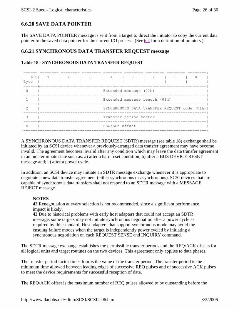
6.6.20 SAVE DATA POINTER
The SAVE DATA POINTER message is sent from a target to direct the initiator to copy the current data pointer to the saved data pointer for the current I/O process. (See 6.4 for a definition of pointers.)
6.6.21 SYNCHRONOUS DATA TRANSFER REQUEST message
Table 18 - SYNCHRONOUS DATA TRANSFER REQUEST
+======-========-========-========-========-========-========-========-========+ | Bit| 7 | 6 | 5 | 4 | 3 | 2 | 1 | 0 | |Byte | | | | | | | | | |======+=======================================================================| | 0 | Extended message (01h) | |------+-----------------------------------------------------------------------| | 1 | Extended message length (03h) | |------+-----------------------------------------------------------------------| | 2 | SYNCHRONOUS DATA TRANSFER REQUEST code (01h)| |------+-----------------------------------------------------------------------| | 3 | Transfer period factor | |------+-----------------------------------------------------------------------| | 4 | REQ/ACK offset | +==============================================================================+
A SYNCHRONOUS DATA TRANSFER REQUEST (SDTR) message (see table 18) exchange shall be initiated by an SCSI device whenever a previously-arranged data transfer agreement may have become invalid. The agreement becomes invalid after any condition which may leave the data transfer agreement in an indeterminate state such as: a) after a hard reset condition; b) after a BUS DEVICE RESET message and; c) after a power cycle.
In addition, an SCSI device may initiate an SDTR message exchange whenever it is appropriate to negotiate a new data transfer agreement (either synchronous or asynchronous). SCSI devices that are capable of synchronous data transfers shall not respond to an SDTR message with a MESSAGE REJECT message.
NOTES 42 Renegotiation at every selection is not recommended, since a significant performance impact is likely. 43 Due to historical problems with early host adapters that could not accept an SDTR message, some targets may not initiate synchronous negotiation after a power cycle as required by this standard. Host adapters that support synchronous mode may avoid the ensuing failure modes when the target is independently power cycled by initiating a synchronous negotiation on each REQUEST SENSE and INQUIRY command.
The SDTR message exchange establishes the permissible transfer periods and the REQ/ACK offsets for all logical units and target routines on the two devices. This agreement only applies to data phases.
The transfer period factor times four is the value of the transfer period. The transfer period is the minimum time allowed between leading edges of successive REQ pulses and of successive ACK pulses to meet the device requirements for successful reception of data.
The REQ/ACK offset is the maximum number of REQ pulses allowed to be outstanding before the
Page 26 of 30SCSI-2 Spec - Logical characteristics
3/2/2006http://www.danbbs.dk/~dino/SCSI/SCSI2-06.html

leading edge of its corresponding ACK pulse is received at the target. This value is chosen to prevent overflow conditions in the device's reception buffer and offset counter. A REQ/ACK offset value of zero shall indicate asynchronous data transfer mode; a value of FFh shall indicate unlimited REQ/ACK offset.
The originating device (the device that sends the first of the pair of SDTR messages) sets its values according to the rules above to permit it to receive data successfully. If the responding device can also receive data successfully with these values (or smaller transfer periods or larger REQ/ACK offsets or both), it returns the same values in its SDTR message. If it requires a larger transfer period, a smaller REQ/ACK offset, or both in order to receive data successfully, it substitutes values in its SDTR message as required, returning unchanged any value not required to be changed. Each device when transmitting data shall respect the limits set by the other's SDTR message, but it is permitted to transfer data with larger transfer periods, smaller REQ/ACK offsets, or both than specified in the other's SDTR message. The successful completion of an exchange of SDTR messages implies an agreement as follows:
Responding device SDTR response Implied agreement a) Non-zero REQ/ACK offset Each device transmits data with a transfer period equal to or greater than and a REQ/ACK offset equal to or less than the values received in the other device's SDTR message. b) REQ/ACK offset equal to zero Asynchronous transfer c) MESSAGE REJECT message Asynchronous transfer
If the initiator recognizes that negotiation is required, it asserts the ATN signal and sends a SDTR message to begin the negotiating process. After successfully completing the MESSAGE OUT phase, the target shall respond with the proper SDTR message. If an abnormal condition prevents the target from returning an appropriate response, both devices shall go to asynchronous data transfer mode for data transfers between the two devices.
Following target response (1) above, the implied agreement for synchronous operation shall be considered to be negated by both the initiator and the target if the initiator asserts the ATN signal and the first message out is either MESSAGE PARITY ERROR or MESSAGE REJECT. In this case, both devices shall go to asynchronous data transfer mode for data transfers between the two devices. For the MESSAGE PARITY ERROR case, the implied agreement shall be reinstated if a retransmittal of the second of the pair of messages is successfully accomplished. After a vendor-specific number of retry attempts (greater than zero), if the target receives a MESSAGE PARITY ERROR message, it shall terminate the retry activity. This may be done either by changing to any other information transfer phase and transferring at least one byte of information or by going to the BUS FREE phase (see 6.1.1). The initiator shall accept such action as aborting the negotiation, and both devices shall go to asynchronous data transfer mode for data transfers between the two devices.
If the target recognizes that negotiation is required, it sends an SDTR message to the initiator. Prior to releasing the ACK signal on the last byte of the SDTR message from the target, the initiator shall assert the ATN signal and respond with its SDTR message or with a MESSAGE REJECT message. If an abnormal condition prevents the initiator from returning an appropriate response, both devices shall go to asynchronous data transfer mode for data transfers between the two devices.
Following an initiator's responding SDTR message, an implied agreement for synchronous operation shall not be considered to exist until the target leaves the MESSAGE OUT phase, indicating that the
Page 27 of 30SCSI-2 Spec - Logical characteristics
3/2/2006http://www.danbbs.dk/~dino/SCSI/SCSI2-06.html

target has accepted the negotiation. After a vendor-specific number of retry attempts (greater than zero), if the target has not received the initiator's responding SDTR message, it shall go to the BUS FREE phase without any further information transfer attempt (see 6.1.1). This indicates that a catastrophic error condition has occurred. Both devices shall go to asynchronous data transfer mode for data transfers between the two devices.
If, following an initiator's responding SDTR message, the target shifts to MESSAGE IN phase and the first message in is MESSAGE REJECT, the implied agreement shall be considered to be negated and both devices shall go to asynchronous data transfer mode for data transfers between the two devices.
The implied synchronous agreement shall remain in effect until a BUS DEVICE RESET message is received, until a hard reset condition occurs, or until one of the two SCSI devices elects to modify the agreement. The default data transfer mode is asynchronous data transfer mode. The default data transfer mode is entered at power on, after a BUS DEVICE RESET message, or after a hard reset condition.
6.6.22 TERMINATE I/O PROCESS
The TERMINATE I/O PROCESS message is sent from the initiator to the target to terminate the current I/O process without corrupting the medium.
With the following exceptions, the target shall terminate the current I/O process and return COMMAND TERMINATED status. The sense key shall be set to NO SENSE. The additional sense code and qualifier are set to I/O PROCESS TERMINATED.
If the associated I/O process involves a data phase, the target shall set the valid bit in the sense data to one and set the information field as follows:
l a) If the command descriptor block specifies an allocation length or parameter list length, the information field shall be set to the difference (residue) between the number of bytes successfully transferred and the requested length.
l b) If the command descriptor block specifies a transfer length field, the information field shall be set as defined in the REQUEST SENSE command (see 8.2.14).
If an error is detected for the associated I/O process the target shall ignore the TERMINATE I/O PROCESS message.
If the operation requested for the associated I/O process has been completed but status has not been returned, the target shall ignore the TERMINATE I/O PROCESS message.
If the target does not support this message or is unable to stop the current I/O process, it shall send a MESSAGE REJECT message to the initiator and continue the I/O process in a normal manner.
The effect of a TERMINATE I/O PROCESS message on the command queue depends on the queue error recovery option specified in the control mode page (see 8.3.3.1) and on whether or not a contingent allegiance condition is generated.
NOTE 44 The TERMINATE I/O PROCESS message provides a means for the initiator to request the target to reduce the transfer length of the current command to the amount that has already been transferred. The initiator can use the sense data to determine the actual number of bytes or blocks that have been transferred. This message is normally used by the
Page 28 of 30SCSI-2 Spec - Logical characteristics
3/2/2006http://www.danbbs.dk/~dino/SCSI/SCSI2-06.html
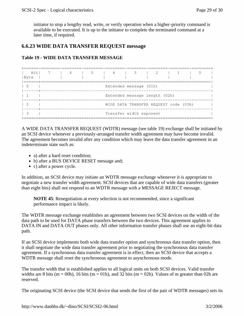
initiator to stop a lengthy read, write, or verify operation when a higher-priority command is available to be executed. It is up to the initiator to complete the terminated command at a later time, if required.
6.6.23 WIDE DATA TRANSFER REQUEST message
Table 19 - WIDE DATA TRANSFER MESSAGE
+======-========-========-========-========-========-========-========-========+ | Bit| 7 | 6 | 5 | 4 | 3 | 2 | 1 | 0 | |Byte | | | | | | | | | |======+=======================================================================| | 0 | Extended message (01h) | |------+-----------------------------------------------------------------------| | 1 | Extended message length (02h) | |------+-----------------------------------------------------------------------| | 2 | WIDE DATA TRANSFER REQUEST code (03h) | |------+-----------------------------------------------------------------------| | 3 | Transfer width exponent | +==============================================================================+
A WIDE DATA TRANSFER REQUEST (WDTR) message (see table 19) exchange shall be initiated by an SCSI device whenever a previously-arranged transfer width agreement may have become invalid. The agreement becomes invalid after any condition which may leave the data transfer agreement in an indeterminate state such as:
l a) after a hard reset condition; l b) after a BUS DEVICE RESET message and; l c) after a power cycle.
In addition, an SCSI device may initiate an WDTR message exchange whenever it is appropriate to negotiate a new transfer width agreement. SCSI devices that are capable of wide data transfers (greater than eight bits) shall not respond to an WDTR message with a MESSAGE REJECT message.
NOTE 45: Renegotiation at every selection is not recommended, since a significant performance impact is likely.
The WDTR message exchange establishes an agreement between two SCSI devices on the width of the data path to be used for DATA phase transfers between the two devices. This agreement applies to DATA IN and DATA OUT phases only. All other information transfer phases shall use an eight-bit data path.
If an SCSI device implements both wide data transfer option and synchronous data transfer option, then it shall negotiate the wide data transfer agreement prior to negotiating the synchronous data transfer agreement. If a synchronous data transfer agreement is in effect, then an SCSI device that accepts a WDTR message shall reset the synchronous agreement to asynchronous mode.
The transfer width that is established applies to all logical units on both SCSI devices. Valid transfer widths are 8 bits (m = 00h), 16 bits (m = 01h), and 32 bits (m = 02h). Values of m greater than 02h are reserved.
The originating SCSI device (the SCSI device that sends the first of the pair of WDTR messages) sets its
Page 29 of 30SCSI-2 Spec - Logical characteristics
3/2/2006http://www.danbbs.dk/~dino/SCSI/SCSI2-06.html

transfer width value to the maximum data path width it elects to accommodate. If the responding SCSI device can also accommodate this transfer width, it returns the same value in its WDTR message. If it requires a smaller transfer width, it substitutes the smaller value in its WDTR message. The successful completion of an exchange of WDTR messages implies an agreement as follows:
Responding Device WDTR Response Implied Agreement -------------------------------- ------------------------------------------- (1) Non-zero transfer width Each device transmits and receives data with a transfer width equal to the responding SCSI device's transfer width. (2) Transfer width equal to zero Eight-bit Data Transfer (3) MESSAGE REJECT message Eight-bit Data Transfer
If the initiator recognizes that negotiation is required, it asserts the ATN signal and sends a WDTR message to begin the negotiating process. After successfully completing the MESSAGE OUT phase, the target shall respond with the proper WDTR message. If an abnormal condition prevents the target from returning an appropriate response, both devices shall go to eight-bit data transfer mode for data transfers between the two devices.
Following target response (1) above, the implied agreement for wide data transfers shall be considered to be negated by both the initiator and the target if the initiator asserts ATN and the first message out is either MESSAGE PARITY ERROR or MESSAGE REJECT. In this case, both devices shall go to eight-bit data transfer mode for data transfers between the two devices. For the MESSAGE PARITY ERROR case, the implied agreement shall be reinstated if a re-transmittal of the second of the pair of messages is successfully accomplished. After a vendor-specific number of retry attempts (greater than zero), if the target receives a MESSAGE PARITY ERROR message, it shall terminate the retry activity. This may be done either by changing to any other information transfer phase and transferring at least one byte of information or by going to the BUS FREE phase (see 6.1.1). The initiator shall accept such action as aborting the negotiation, and both devices shall go to eight-bit data transfer mode for data transfers between the two devices.
If the target recognizes that negotiation is required, it sends a WDTR message to the initiator. Prior to releasing the ACK signal on the last byte of the WDTR message from the target, the initiator shall assert the ATN signal and respond with its WDTR message or with a MESSAGE REJECT message. If an abnormal condition prevents the initiator from returning an appropriate response, both devices shall go to eight-bit data transfer mode for data transfers between the two devices.
Page 30 of 30SCSI-2 Spec - Logical characteristics
3/2/2006http://www.danbbs.dk/~dino/SCSI/SCSI2-06.html
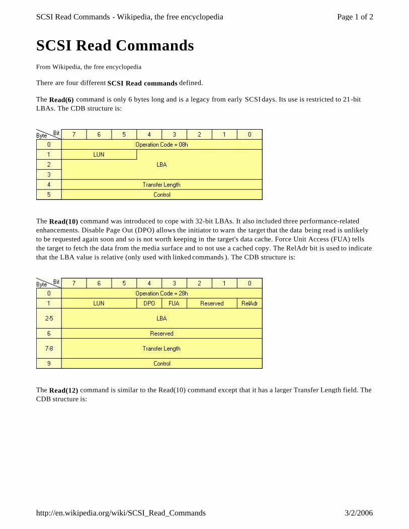
SCSI Read Commands From Wikipedia, the free encyclopedia
There are four different SCSI Read commands defined.
The Read(6) command is only 6 bytes long and is a legacy from early SCSI days. Its use is restricted to 21-bit LBAs. The CDB structure is:
The Read(10) command was introduced to cope with 32-bit LBAs. It also included three performance-related enhancements. Disable Page Out (DPO) allows the initiator to warn the target that the data being read is unlikely to be requested again soon and so is not worth keeping in the target's data cache. Force Unit Access (FUA) tells the target to fetch the data from the media surface and to not use a cached copy. The RelAdr bit is used to indicate that the LBA value is relative (only used with linked commands ). The CDB structure is:
The Read(12) command is similar to the Read(10) command except that it has a larger Transfer Length field. The CDB structure is:
Page 1 of 2SCSI Read Commands - Wikipedia, the free encyclopedia
3/2/2006http://en.wikipedia.org/wiki/SCSI_Read_Commands

n This page was last modified 15:00, 6 January 2006. n All text is available under the terms of the GNU Free
Documentation License (see Copyrights for details). Wikipedia® is a registered trademark of the Wikimedia Foundation, Inc.
n Privacy policy n About Wikipedia n Disclaimers
The Read Long command is used for Error Correcting Code (ECC) compliant data previously written by a Write Long command. The CORRCT bit defines whether or not the target is allowed to correct any errors found before returning the data to the target. The CDB structure is:
Retrieved from " http://en.wikipedia.org/wiki/SCSI_Read_Commands"
Category: SCSI
Page 2 of 2SCSI Read Commands - Wikipedia, the free encyclopedia
3/2/2006http://en.wikipedia.org/wiki/SCSI_Read_Commands