lvd scsi interface unit interface scsi lvd lvd scsi …...lvd scsi interface unit interface scsi lvd...
TRANSCRIPT

LVD SCSI INTERFACE UNITINTERFACE SCSI LVDLVD SCSILVD SCSI
DRM-ULV16
Operating InstructionsMode d’emploi

2<DRC1290>
The exclamation point within an equilateral triangle is intended to alert the user to the presence of important operating and maintenance (servicing) instructions in the literature accompanying the appliance.
The lightning flash with arrowhead symbol, within an equilateral triangle, is intended to alert the user to the presence of uninsulated "dangerous voltage" within the product's enclosure that may be of sufficient magnitude to constitute a risk of electric shock to persons.
CAUTION:TO PREVENT THE RISK OF ELECTRIC SHOCK, DO NOT REMOVE COVER (OR BACK). NO USER-SERVICEABLE PARTS INSIDE. REFER SERVICING TO QUALIFIED SERVICE PERSONNEL.
CAUTIONRISK OF ELECTRIC SHOCK
DO NOT OPEN
IMPORTANT
D3-4-2-1-1_En-A
Ce point d’exclamation, placé dans un triangle équilatéral, a pour but d’attirer l’attention de l’utilisateur sur la présence, dans les documents qui accompagnent l’appareil, d’explications importantes du point de vue de l’exploitation ou de l’entretien.
Ce symbole de l’éclair, placé dans un triangle équilatéral, a pour but d’attirer l’attention de l’utilisateur sur la présence, à l’intérieur du coffret de l’appareil, de “tensions dangereuses” non isolées d’une grandeur suffisante pour représenter un risque d’électrocution pour les êtres humains.
IMPORTANT
ATTENTION:POUR ÉVITER TOUT RISQUE D’ÉLECTROCUTION, NE PAS ENLEVER LE COUVERCLE (NI LE PANNEAU ARRIÈRE). AUCUNE PIÈCE RÉPARABLE PAR L’UTILISATEUR NE SE TROUVE À L’INTÉRIEUR. CONFIER TOUT ENTRETIEN À UN PERSONNEL QUALIFIÉ UNIQUEMENT.
ATTENTIONDANGER D´ELECTROCUTION
NE PAS OUVRIR
D3-4-2-1-1_Fr
NOTE: This equipment has been tested and found to comply with the limits for a Class A digital device, pursuant to Part 15 of the FCC Rules. These limits are designed to provide reasonable protection against harmful interference when the equipment is operated in a commercial environment. This equipment generates, uses, and can radiate radio frequency energy and, if not installed and used in accordance with the instruction manual, may cause harmful interference to radio communications. Operation of this equipment in a residential area is likely to cause harmful interference in which case the user will be required to correct the interference at his own expense. D8-10-1-1_En
CAUTION: This product satisfies FCC regulations when shielded cables and connectors are used to connect the unit to other equipment. To prevent electromagnetic interference with electric appliances such as radios and televisions, use shielded cables and connectors for connections. D8-10-3a_En
USE ONLY WITH PIONEER MODELS DRM-7000 AND DRM-3000. D1-4-1-12_En
WARNINGThis equipment is not waterproof. To prevent a fire or shock hazard, do not place any container filed with liquid near this equipment (such as a vase or flower pot) or expose it to dripping, splashing, rain or moisture. D3-4-2-1-3_A_En
AVERTISSEMENTCet appareil n’est pas étanche. Pour éviter les risques d’incendie et de décharge électrique, ne placez près de lui un récipient rempli d’eau, tel qu’un vase ou un pot de fleurs, et ne l’exposez pas à des gouttes d’eau, des éclaboussures, de la pluie ou de l’humidité. D3-4-2-1-3_A_Fr
Information to UserAlteration or modifications carried out without appropriate authorization may invalidate the user’s right to operate the equipment.
D8-10-2_En
This Class A digital apparatus complies with Canadian ICES-003.
Cet appareil numérique de la Classe A est conforme à la norme NMB-003 du Canada. D8-10-1-4_EF
IMPORTANT NOTICE – RECORD THE MODEL NUMBER AND SERIAL NUMBERS OF THIS EQUIPMENT BELOW.THE NUMBERS ARE ON THE TOP.
MODEL NO. SERIAL NO.
KEEP THESE NUMBERS FOR FUTURE USE. D1-4-2-6-2_En
DRM-ULV16
[For Canadian model/Pour le modèle Canadien]

3<DRC1290>
[For Taiwanese model]
[For Korean model]
WARNING: Handling the cord on this product or cords associated with accessories sold with the product will expose you to lead, a chemical known to the State of California and other governmental entities to cause cancer and birth defects or other reproductive harm.
D36-P4_EnWash hands after handling
WarningThis is a class A product. In a domestic environment this product may cause radio interference in which cause the user may be required to take adequate measures. D51-6_En
[For Australian and New Zealander models]

4En <DRC1290>
Thank you for purchasing this Pioneer product. Before using the product, please readthese Operating Instructions fully in order to get the best possible performance fromyour purchase.This unit has been designed exclusively as an optional unit to be used with Pioneer discchangers DRM-7000 and DRM-3000; as a result, it cannot be used alone or incombination with other products.
Features
Precautions in Use
¶ Be sure to read these Operating Instructions before use.¶ After reading these Operating Instructions store them safely to allow later consultation
if necessary.¶ Do not use this unit in locations exposed to high concentrations of dust, high
temperature, or high humidity.¶ Do not subject the unit to vibrations or impacts.¶ Do not allow the unit to be exposed to foreign objects or liquids.¶ In the event that condensation occurs on the unit, turn off the power and do not
attempt to install it until it has dried thoroughly, since damage may result.¶ Do not attempt to perform internal inspections or modifications.¶ If any unnatural smell or noise should be noticed during use, immediately turn off
power and have the unit inspected.
Note:Installation of this product requires a high level of technical expertise, and shouldbe undertaken only by professional Pioneer service personnel. For details, consultyour dealer.
Pioneer disclaims all responsibility for any loss of data, or other incidental
damages arising from the use or malfunction of this product. All important
data should be backed up to prevent loss.
Use of this product allows SE-supported 700/300 disc changers to be modified so as tosupport LVD host-bus adapters.
(SE: Single-Ended SCSI LVD: Low-Voltage Differential SCSI)¶ A maximum of 15 devices (including changers) can be connected (composed of
both SE and LVD devices).¶ Maximum connection cable length: 12 m (LVD side, including internal connections)¶ Supports Ultra 160 SCSI standards* (LVD side)
* Transfer speed may differ depending on the devices connected.

5<DRC1290> En
En
glish
Installation Precautions
Nomenclature
Take the following precautions into consideration when installing:¶ This unit cannot be connected to an SE host bus adapter.
Always use an LVD host bus adapter.¶ This unit cannot be used together with Power supply unit DRM-PW701 due to drive
installation limitations.¶ Turn off power to the host computer and changer before connecting SCSI cables.
Rear Connectors
1 SE SCSI termination switch (CHANGER)
Use to set changer’s SCSI terminator ON/OFF. Factory default: ON
2 SCSI ID switch (CHANGER)
Use to set the changer’s SCSI ID. Pressing the upper protrusion causes the numberto decrement, while pressing the lower protrusion increments the number. Factorydefault: 6
3 LVD SCSI interface connector
Connect using the supplied (or optionally purchased) SCSI Cable (LVD), or suppliedSCSI Terminator (LVD).
4 SE SCSI interface connector
Connect to the changer’s supplied SCSI Cable (SE).
Note:
Avoid touching the connectors, since faulty connection or damage from staticelectricity may result.

6En <DRC1290>
Connections
Host
LVD Drive 1
LVD Drive 2
DRM-ULV16 card
SE Drive 2
SE Drive 1
Changer card(OFF)
(OFF)
(ON)
For connection information refer to the "SCSI Connection Manual" or consult yourdealer.
Restrictions:7 Connection Cable Length
LVD-side: 12 m or less
Total length of cables, including those inside the component (when multiple changers areconnected, this includes the cables between the changers)
SE-side: 3 m or less
Total length of cable for each changer, including that internal to the component.7 Connected Units
Total LVD and SE devices (including changers, but not including host bus adapters)
With one changer: 9 max*With multiple changers: 15 max*
* The maximum permissible number of changers differs depending on the drive; for detailsconsult your drive Operating Instructions.
Further, the total number of SE devices (including changers):
Regardless of the number of changers: 7 max (however, no more than 4 devices per changer)* Due to restrictions on cable lengths, SE drives are to be installed in drive bays 1 – 3.* SE devices should be given SCSI IDs of 0 – 6.* This unit cannot be used together with Power supply unit DRM-PW701 due to drive installation
limitations.
[Connection Example 1] With 1 Changer (LVD and SE drive installation)
Changer internal cable length
A LVD: About 0.25 mB LVD: About 0.7 mC SE: About 0.6 mD SE: About 0.5 m
Changer (SE) x 1SE drive (SE) x 2LVD drive (LVD) x 2DRM-ULV16 x 1
Connection Cable Lengths
1 CC-200 or CC-201 x 1✩
SCSI Cable (LVD): 2.5 m2 Accessory x 1
SCSI Cable (LVD): 0.55 m3 DRM-LN721 x 1✩
LVD drive connector panel (for 2 drives)4 Accessory x 1
SCSI Terminator (LVD)5 Changer accessory x 1
SCSI Cable (SE): 0.35 m✩: Option
LVD Line: About 4.0 m SE Line: About 1.45 m
Host computer * SE device SCSI terminator switch setting

7<DRC1290> En
En
glish
Connections
[Connection Example 2] With 1 Changer (LVD drive only)
Changer internal cable length
A LVD: About 0.25 mB LVD: About 0.7 m
Changer (SE) x 1LVD drive (LVD) x 2DRM-ULV16 x 1
Connection Cable Lengths
1 CC-200 or CC-201 x 1✩
SCSI Cable (LVD): 2.5 m2 Accessory x 1
SCSI Cable (LVD): 0.55 m3 DRM-LN721 x 1✩
LVD drive connector panel (for 2 drives)4 Accessory x 1
SCSI Terminator (LVD)✩: Option
LVD Line: About 4.0 m
* SE device SCSI terminator switch setting
Host
LVD Drive 1
LVD Drive 2
DRM-ULV16 card
Changer card(ON)
[Connection Example 3] With 1 Changer (SE drive only)
Changer internal cable length
A LVD: About 0.25 mB SE: About 0.6 mC SE: About 0.5 m
Changer (SE) x 1SE drive (SE) x 2DRM-ULV16 x 1
Connection Cable Lengths
1 CC-200-8 or CC-201-8 x 1✩
SCSI Cable (LVD): 8 m2 Accessory x 1
SCSI Terminator (LVD)3 Changer accessory x 1
SCSI Cable (SE): 0.35 m✩: Option
LVD Line: About 8.25 m SE Line: About 1.45 m
* SE device SCSI terminator switch setting
Host
DRM-ULV16 card
SE Drive 2
SE Drive 1
Changer card(OFF)
(OFF)
(ON)

8En <DRC1290>
Connection
[Connection Example 4] With 3 Changers (daisy chain)
Changer internal cable length
A LVD: About 0.25 mB LVD: About 0.7 mC SE: About 0.6 mD SE: About 0.5 m
Changer (SE) x 3SE drive (SE) x 4LVD drive (LVD) x 3DRM-ULV16 x 3
Connection Cable Lengths
1 CC-200 or CC-201 x 1✩
SCSI Cable (LVD): 2.5 m2 Accessory x 3
SCSI Cable (LVD): 0.55 m3 DRM-LN721 x 3✩
LVD drive connector panel (for 2 drives)4 Accessory x 1
SCSI Terminator (LVD)5 CC-201 x 2✩
SCSI Cable (LVD): 2.5 m6 Changer accessory x 3
SCSI Cable (SE): 0.35 m✩: Option
LVD Line: About 12.0 m SE Line: About 1.45 m (1st changer)
About 1.45 m (2nd changer) About 1.45 m (3rd changer)
* SE device SCSI terminator switch setting
Host
LVD Drive 1
DRM-ULV16 card
SE Drive 2
SE Drive 1
Changer card
LVD Drive 1
SE Drive 1
DRM-ULV16 card
LVD Drive 1
SE Drive 1
DRM-ULV16 card
(OFF)
Changer card(OFF)
Changer card(OFF)
(OFF)
(ON)
(ON)
(ON)
1st changer
2nd changer
3rd changer

9<DRC1290> En
En
glish
Specifications
Published by Pioneer Corporation.Copyright © 2006 Pioneer Corporation.All rights reserved.
[Interface]SE side SCSI-2*1 Amphenol 50-pin x 1LVD side Ultra 160 SCSI*1 Half-pitch 68-pin x 2
*1: Transfer speed may differ depending on the devices connected.
[Maximum cable connection length (including internal connection cables)]SE side : 3 m *2LVD side : 12 m *2
[Maximum units connectable]Total LVD and SE devices (including changers, but not including host bus adapters)
15 *2 *2: For SCSI cable and SCSI Terminator (LVD) use provided accessory or Pioneer-recommended
product.[Other specifications]
Power DC +5 V, 0.7 ADimensions
Body (internal changer dimension)140.1 (W) x 117.2 (D) x 70.1 (H) mm
Rear connectors (not including cables)100.0 (W) x 40.2 (D) x 82.0 (H) mm
Weight 0.68 kgTemperature during use (ambient changer temperature)
+5 °C – +35 °CHumidity during use (ambient changer humidity)
5% – 85% (without condensation)Temperature during storage
–40 °C – +60 °CHumidity during storage
5% – 90% (without condensation)
[Accessories]SCSI Terminator (LVD) x 1SCSI Cable (LVD): 0.55 m x 1÷ Parts noted below are used when connecting to changerConnector Ass’y x 2Screws x 4Posts x 2Cushion x 1Edge guard x 1Cable binders x 3
7 To assure optimum performance, use only SCSI Cables and SCSI Terminator (LVD) provided asaccessories or those recommended by Pioneer.
7 The specifications and design of this product are subject to change without notice, due toimprovement.

10Fr <DRC1290>
Nous vous remercions de votre achat de ce produit Pioneer. Avant de le mettre enservice, veuillez lire attentivement ce Mode d’emploi afin d'obtenir les meilleurs résultatspossibles de votre investissement. Cet appareil est conçu exclusivement comme unitéen option à utiliser avec les changeurs de disque Pioneer DRM-7000 et DRM-3000. Parconséquent, il ne pourra pas être utilisé seul ou combiné à d’autres appareils.
Caractéristiques
Précautions d’utilisation
¶ Prenez soin de lire ce Mode d’emploi avant l’utilisation de l’appareil.¶ Après l’avoir lu, rangez ce Mode d’emploi dans un endroit approprié, de manière à
pouvoir vous y référer ultérieurement en cas de besoin.¶ N’utilisez pas cet appareil dans des endroits très poussiéreux, très chauds ou très
humides.¶ Ne soumettez pas l’appareil à des vibrations ou des chocs.¶ Évitez toute infiltration de corps étrangers ou de liquides.¶ Si une condensation se produit sur l’appareil, coupez son alimentation électrique et,
sous peine d’y provoquer des dégâts, n’essayez pas de l’installer tant qu’il n’est pasparfaitement sec.
¶ N’essayez pas de procéder à des inspections ou des modifications à l’intérieur del’appareil.
¶ Si vous décelez une odeur ou un bruit anormal pendant l’emploi de l’appareil, mettez-le immédiatement hors tension et faites-le inspecter.
Remarque:L’installation de cet appareil exige des compétences techniques de haut niveau etelle doit donc être confiée uniquement à un professionnel du service Pioneer.Pour plus de détails, veuillez consulter votre revendeur.
Pioneer n’assume aucune responsabilité en cas de perte de données ou
d’autres dommages et intérêts indirects, résultant de l’emploi ou d’un
dysfonctionnement de ce produit. Toutes les données importantes doivent
être sauvegardées de manière à éviter leur perte.
L’emploi de cet appareil permet de modifier des changeurs de 700/300 disquessupportés SE de manière à prendre en compte des adaptateurs de bus hôte.
(SE : périphérique SCSI en mode asymétrique ;LVD : périphérique SCSI à différentiel basse tension)
¶ Un maximum de 15 périphériques (changeurs compris) peuvent être raccordés(associations de périphériques SE et LVD).
¶ Longueur maximale du câble de connexion: 12 m (côté LVD, y compris les connexionsinternes)
¶ Prend en compte les normes SCSI Ultra 160 * (côté LVD).*La vitesse de transfert peut varier en fonction des périphériques raccordés.

11<DRC1290> Fr
Fra
nçais
Précautions à l’installation
Nomenclature des organes
Veuillez tenir compte des précautions suivantes lors de l’installation:¶ Cet appareil ne peut pas être raccordé à un adaptateur de bus hôte SE. Utilisez
uniquement un adaptateur de bus hôte LVD.¶ Cet appareil ne peut pas être utilisé avec un bloc d’alimentation électrique DRM-
PW701, en raison des limitations d’installation du lecteur.¶ Coupez l’alimentation électrique à l’ordinateur hôte et au changeur avant de brancher
les Câbles SCSI.
Connecteurs du panneau arrière
1 Commutateur de terminaison SE SCSI (CHANGER)
Il permet d’activer (ON) ou désactiver (OFF) la terminaison SCSI du changeur. Réglagepar défaut: ON (activé).
2 Commutateur de code d’identification SCSI (CHANGER)
Pour régler le code d’identification (ID) SCSI du changeur. Appuyez sur l’onglet duhaut pour augmenter les chiffres ou sur celui du bas pour les diminuer. Réglage pardéfaut: 6.
3 Connecteur d’interface LVD SCSI
Raccordez au moyen du Câble SCSI (LVD) fourni (ou acheté comme option) ou aumoyen du Terminateur SCSI (LVD) fourni.
4 Connecteur d’interface SE SCSI
Raccordez au Câble SCSI fourni avec le changeur (SE).
Remarque:
Évitez de toucher les connecteurs, car des branchements défectueux ou des pannespourraient résulter du fait de l’électricité statique produite lors le contact.

12Fr <DRC1290>
Hôte
Lecteur LVD 1
Lecteur LVD 2
Carte DRM-ULV16
Lecteur SE 2
Lecteur SE 1
Carte de changeur(désactivé)
(désactivé)
(activé)
Branchements
En ce qui concerne les informations sur les branchements, reportez-vous au“Manuel de SCSI connexion” ou consultez votre revendeur.
Restrictions7 Longueur du câble de connexion
Côté LVD: 12 m ou moins
Longueur totale des câbles, y compris ceux à l’intérieur des composants (lorsque plusieurschangeurs sont raccordés, ceci inclut les câbles reliant les changeurs)
Côté SE: 3 m ou moins
Longueur totale du câble de chaque changeur, y compris ceux à l’intérieur du composant.7 Périphériques raccordés
Nombre total de périphériques LVD et SE (y compris les changeurs, mais non compris les
adaptateurs de bus hôte)
Avec un changeur: 9 max. *Avec plusieurs changeurs: 15 max. *
* Le nombre maximum de changeurs autorisés varie selon le lecteur; pour plus de détails,reportez-vous au Mode d’emploi.
En outre, le nombre total de périphériques SE (y compris les changeurs):
Quel que soit le nombre des changeurs: 7 max. (cependant, pas plus de 4 périphériques parchangeur)
* Du fait des limitations imposées à la longueur des câbles, les périphériques SE devront êtreinstallés dans les baies de lecteur 1-3.
* Les périphériques SE doivent recevoir les codes d’identification (ID) SCSI de 0 à 6.* Cet appareil ne peut pas être utilisé avec le bloc d’alimentation électrique DRM-PW701 en
raison des limitations d’installation des lecteurs.
[1er exemple de connexion] Avec un changeur (installation de lecteur LVD et SE)
Longueur de câble interne de changeur
A LVD : Env. 0,25 m B LVD : Env. 0,7 mC SE : Env. 0,6 m D SE : Env. 0,5 m
Changeur (SE) x 1Lecteur SE (SE) x 2Lecteur LVD (LVD) x 2DRM-ULV16 x 1
Longueur des câbles de connexion1 CC-200 ou CC-201 x 1 ✩
Câble SCSI (LVD) : 2,5 m2 Câble accessoire x 1
Câble SCSI (LVD) : 0, 55 m3 DRM-LN721 x 1 ✩
Panneau de connexion LVD (pour 2 lecteurs)4 Accessoire x 1
Terminateur SCSI (LVD)5 Accessoire de changeur x 1
Câble SCSI (SE) : 0,35 m✩: En option
Ligne LVD: Env. 4,0 m Ligne SE: Env. 1,45 m
* Réglage du commutateur de terminateur
SCSI du périphérique SE
Ordinateur hôte
13<DRC1290> Fr
Fra
nçais
Branchements
Hôte
Lecteur LVD 1
Lecteur LVD 2
Carte DRM-ULV16
Carte de changeur(activé)
Hôte
Carte DRM-ULV16
Lecteur SE 2
Lecteur SE 1
Carte de changeur(désactivé)
(désactivé)
(activé)
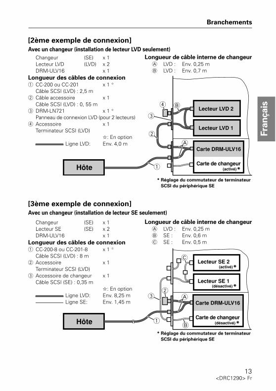
[2ème exemple de connexion]
Avec un changeur (installation de lecteur LVD seulement)
Longueur de câble interne de changeur
A LVD : Env. 0,25 mB LVD : Env. 0,7 m
* Réglage du commutateur de terminateur
SCSI du périphérique SE
Changeur (SE) x 1Lecteur LVD (LVD) x 2DRM-ULV16 x 1
Longueur des câbles de connexion
1 CC-200 ou CC-201 x 1 ✩
Câble SCSI (LVD) : 2,5 m2 Câble accessoire x 1
Câble SCSI (LVD) : 0, 55 m3 DRM-LN721 x 1 ✩
Panneau de connexion LVD (pour 2 lecteurs)4 Accessoire x 1
Terminateur SCSI (LVD)✩: En option
Ligne LVD: Env. 4,0 m
[3ème exemple de connexion]
Avec un changeur (installation de lecteur SE seulement)
Longueur de câble interne de changeur
A LVD : Env. 0,25 mB SE : Env. 0,6 mC SE : Env. 0,5 m
Changeur (SE) x 1Lecteur SE (SE) x 2DRM-ULV16 x 1
Longueur des câbles de connexion
1 CC-200-8 ou CC-201-8 x 1 ✩
Câble SCSI (LVD) : 8 m2 Accessoire x 1
Terminateur SCSI (LVD)3 Accessoire de changeur x 1
Câble SCSI (SE) : 0,35 m✩: En option
Ligne LVD: Env. 8,25 m Ligne SE: Env. 1,45 m
* Réglage du commutateur de terminateur
SCSI du périphérique SE

14Fr <DRC1290>
Hôte
Carte DRM-ULV16
Carte de changeur(désactivé)
Lecteur LVD 1
Carte DRM-ULV16
Lecteur SE 2
Lecteur SE 1
Carte de changeur(désactivé)
(désactivé)
(activé)
Lecteur LVD 1
Lecteur SE 1(activé)
Carte DRM-ULV16
Carte de changeur(désactivé)
Lecteur LVD 1
Lecteur SE 1(activé)
Branchements
1er changeur
2ème changeur
3ème changeur
[4ème exemple de connexion] Avec 3 changeurs (Connexion en guirlande)
Longueur de câble interne de changeur
A LVD : Env. 0,25 mB LVD : Env. 0,7 mC SE : Env. 0,6 mD SE : Env. 0,5 m
Changeur (SE) x 3Lecteur SE (SE) x 4Lecteur LVD (LVD) x 3DRM-ULV16 x 3
Longueur des câbles de connexion
1 CC-200 ou CC-201 x 1 ✩
Câble SCSI (LVD) : 2,5 m2 Câble accessoire x 3
Câble SCSI (LVD) : 0, 55 m3 DRM-LN721 x 3 ✩
Panneau de connexion LVD (pour 2 lecteurs)4 Accessoire x 1
Terminateur SCSI (LVD)5 CC-201 x 2 ✩
Câble SCSI (LVD) : 2,5 m6 Accessoire de changeur x 3
Câble SCSI (SE) : 0,35 m✩: En option
Ligne LVD: Env. 12,0 m Ligne SE: Env. 1,45 m (1er changeur)
Env. 1,45 m (2ème changeur) Env. 1,45 m (3ème changeur)
* Réglage du commutateur de terminateur
SCSI du périphérique SE

15<DRC1290> Fr
Fra
nçais
Publication de Pioneer Corporation.© 2006 Pioneer Corporation.Tour droits de reproduction et de traduction réservés.
Fiche technique
[Interface]Côté SE SCSI-2*1 Amphenol à 50 broches x 1Côté LV Ultra 160 SCSI*1 Demi-pas à 68 broches x 2
*1: La vitesse de transfert peut varier en fonction des périphériques raccordés.
[Longueur maximale des connexions par câbles (y compris les câbles de connexion
internes)]Côté SE: 3 m *2Côté LVD: 12 m *2
[Nombre maximum de périphériques raccordables]Nombre total de périphériques LVD et SE (y compris les changeurs, mais non compris lesadaptateurs de bus hôte)
15 *2 *2: Comme Câble SCSI et Terminateur SCSI (LVD), utilisez les produits fournis ou
recommandés par Pioneer.[Autres spécifications]
Alimentation CC +5 V, 0,7 ADimensions
Boîtier (dimensions internes du changeur)140,1 x 117,2 x 70,1 mm (L x P x H)
Connecteurs arrière (câbles non compris)100,0 x 40,2 x 82,0 mm (L x P x H)
Poids 0,68 kgTempérature de fonctionnement (Température ambiante de changeur)
De +5 à +35 °CHumidité de fonctionnement (Humidité ambiante de changeur)
De 5 à 85 % (sans condensation)Température d’entreposage
De –40 à +60 °CHumidité d’entreposage
De 5 à 90 % (sans condensation)
[Accessoires]Terminateur SCSI (LVD) x 1Câble SCSI (LVD): 0,55 m x 1÷ Les pièces ci-dessous servent lors du branchement au changeur.Ensemble de connecteur x 2Vis x 4Montants x 2Coussinet x 1Protection d’arête x 1Serre-câbles x 3
7 Pour garantir des performances optimales, utilisez uniquement les Câbles SCSI et le TerminateurSCSI (LVD) fournis comme accessoires ou ceux recommandés par Pioneer.
7 Spécifications et design sous réserve de changements sans préavis en raison d’améliorationséventuelles.

16ChK <DRC1290>
承蒙惠购本先锋牌产品,甚表示感谢。务请在使用本机之前通读本操作说明书,以便让本机充分发挥其功能并有效利用本机。本机为换盘机“DRM-7000型”和“DRM-3000型”专用的任选装置。本机不能单独使用或安装在其他机器上使用。
特征
使用注意事项
<注意>■由于本机的安装需要高度的专业知识和为安全,安装工作由本公司服务人员进行。详情请与本机经销店商量。
对于使用本机,或因本机故障而产生的数据损失,以及其他直接或间接的损害,本公司概不负其责任,请预先予以谅解。为预防万一,有关重要的数据请作好备份(拷贝)。
通过利用本机,使SE对应700/300张换盘机能够与LVD主机总线适配器对应。(SE∶单端SCSI LVD∶低压差分SCSI)
● SE和 LVD设备加在一起最多能够连接 15个设备(包括换盘机)。● 最大连接线长度12m(LVD侧,包括内部连接)● 对应 Ultra 160 SCSI规格* (LVD侧)
* 传送速度依所连接设备有所不同。
●在操作本机之前,必须阅读本操作说明书。●读完后,必须妥善保管。如果使用中遇到任何不明白之处或功能失灵,将会帮助您解决问题。
●请勿在灰尘多的场所,或在高温、高湿的场所使用。●请勿对本机施加冲击或振动。●注意不要让异物或水进入机内。●如果造成本机结露时,必须以断开电源的状态搁置,不要进行安装作业直至完全干燥。否则会有导致故障的可能性。
●切忌进行机内检查或改造。●如果本机使用中产生异常的声音或气味,必须断开电源并请有关人员进行检查。

17<DRC1290> ChK
设置注意事项
各部名称及其功能
后面端子部
设置本机时,请注意下列事项∶●本机不能与SE的主机总线适配器进行连接。必须使用LVD的主机总线适配器。
●因为驱动器安装台数上的限制,无法进行本机与增设电源装置“D R M -PW701”的并用。
●连接SCSI连接线时,以断开主计算机和换盘机电源的状态进行连接。
①SE SCSI端接开关(换盘机)设定换盘机SCSI端接器的 ON/OFF(接通/断开)。出厂时设定成“ON”。
②SCSI ID开关(换盘机)用以设定换盘机的SCSI ID。按上面的突起时数字减小,按下面的突起时数字增大。出厂时设定成“6”。
③LVD SCSI接口端子用以连接配备的或任选的SCSI连接线(LVD),配备的SCSI连接头(LVD)。
④SE SCSI接口端子用以向换盘机连接配备的SCSI连接线(SE)。
注意∶请勿触摸各端子的端子部。否则成为接触不良或静电破坏的原因。

18ChK <DRC1290>
连接方法
有关连接事宜,请参照“SCSI连接说明书”,或与本机经销店商量。
[限制事项]■电缆连接长度LVD侧 12m以下包括机器内部的连接线全长(连接复数台换盘机时包括换盘机之间的连接线长度)
SE侧 3m以下每 1台换盘机包括机器内部的连接线全长
■连接台数LVD·SE设备的总计台数(包括换盘机,不包括主机总线适配器)换盘机 1台时 最大 9台*连接复数台换盘机时 最大 15台*
* 最大可装载台数依驱动器有所不同,详情见所使用驱动器的操作说明书。除上述之外,SE设备的总计台数(包括换盘机)不管是换盘机的台数如何,最多 7台(但每一台换盘机最多 4台)
※由于连接线长度的限制,SE驱动器需安装在驱动器间 No.1~No.3。※ SE设备的 SCSI ID需设定成 0~6。※因驱动器安装台数的限制,无法进行“DRM-ULV16”和增设电源装置“DRM-PW701”的并用。
[连接例1]换盘机1台(装备LVD和SE驱动器)
换盘机内部的连接线长度A LVD∶ 约0.25mB LVD∶ 约0.7mC SE∶ 约0.6mD SE∶ 约0.5m
换盘机 (SE) ×1SE驱动器 (SE) ×2LVD驱动器 (LVD) ×2DRM-ULV16 × 1
连接电缆类① CC-200或 CC-201 × 1☆SCSI连接线(LVD)∶2.5m
② 附件 × 1SCSI连接线(LVD)∶0.55m
③ DRM-LN721 × 1☆LVD连接板(双驱动器用)
④ 附件 ×1SCSI连接头(LVD)
⑤ 换盘机附件 ×1SCSI连接线(SE)∶0.35m
☆∶任选零件 LVD线路∶ 约4.0m SE线路∶ 约1.45m
* SE设备SCSI端接开关的设定

19<DRC1290> ChK
连接方法
[连接例2]换盘机1台(只装备LVD驱动器)
* SE设备SCSI端接开关的设定
换盘机 (SE) ×1LVD驱动器 (LVD) ×2DRM-ULV16 × 1
连接电缆类① CC-200或 CC-201 × 1☆SCSI连接线(LVD)∶2.5m
② 附件 × 1SCSI连接线(LVD)∶0.55m
③ DRM-LN721 × 1☆LVD连接板(双驱动器用)
④ 附件 ×1SCSI连接头(LVD)
☆∶任选零件 LVD线路∶ 约4.0m
换盘机内部的连接线长度A LVD∶ 约0.25mB LVD∶ 约0.7m
[连接例3]换盘机1台(只装备SE驱动器)
换盘机内部的连接线长度A LVD∶ 约0.25mB SE∶ 约0.6mC SE∶ 约0.5m
换盘机 (SE) ×1SE驱动器 (SE) ×2DRM-ULV16 × 1
连接电缆类① CC-200-8或 CC-201-8× 1☆SCSI连接线(LVD)∶8m
② 附件 ×1SCSI连接头(LVD)
③ 换盘机附件 ×1SCSI连接线(SE)∶0.35m
☆∶任选零件 LVD线路∶ 约8.25m SE线路∶ 约1.45m
* SE设备SCSI端接开关的设定

20ChK <DRC1290>
连接方法
[连接例4]换盘机3台菊花链连接
换盘机 (SE) ×3SE驱动器 (SE) ×4LVD驱动器 (LVD) ×3DRM-ULV16 × 3
连接电缆类① CC-200或 CC-201 × 1☆SCSI连接线(LVD)∶2.5m
② 附件 × 3SCSI连接线(LVD)∶0.55m
③ DRM-LN721 × 3☆LVD连接板(双驱动器用)
④ 附件 ×1SCSI连接头(LVD)
⑤CC-201 × 2☆SCSI连接线(LVD)∶2.5m
⑥ 换盘机附件 ×3SCSI连接线(SE)∶0.35m
☆∶任选零件 LVD线路∶约12.0m SE线路∶约1.45m(第1台)
约1.45m(第2台) 约1.45m(第3台)
换盘机内部的连接线长度A LVD∶ 约0.25mB LVD∶ 约0.7mC SE∶ 约0.6mD SE∶ 约0.5m
* SE设备SCSI端接开关的设定
第1台
第2台
第3台
21<DRC1290> ChK
规格
【输出入端子】
SE侧 SCSI-2 *1 非酚醛 50Pin× 1LVD侧 Ultra 160 SCSI*1 半间距 68Pin× 2
*1 传送速度依所连接设备有所不同。【连接线最大连接长度(包括内部接线)】
SE侧 3m*2LVD侧 12m*2
【最大连接台数】
LVD·SE设备的总计台数(包括换盘机,不包括主机总线适配器)15台 *2
*2 SCSI连接线及 SCSI连接头(LVD)请使用附件或本公司推荐产品。【其他】电源 DC+ 5V,0.7A外形尺寸主体部(换盘机主体内置部)
140.1(宽)× 117.2(深)× 70.1(高)mm背面端子部(除连接线部)
100.0(宽)× 40.2(深)× 82.0(高)mm质量 0.68kg工作温度(换盘机外部环境温度)
+5℃~+35℃工作湿度(换盘机外部环境湿度)
5%~85%(应无结露)保存温度 -40℃~+60℃保存湿度 5%~90%(应无结露)
【附件】
SCSI连接头(LVD) × 1SCSI连接线(LVD)∶0.55m × 1÷以下为将本机安装在换盘机上时所使用的零件。端子组件 × 2小螺钉 × 4柱 × 2垫子 × 1边缘保护器 × 1结合件 × 3
7 为确保产品质量,SCSI连接线和SCSI连接线(LVD)请使用本机附件或本公司推荐产品。
7 因改良起见,上述规格及外观可能会有变更,恕不另行通知。

22Ja <DRC1290>
このたびは、パイオニアの製品をお買い求めいただきまして、まことにありがとうございます。本機の機能を十分に発揮させて効果的にご利用いただくために、この取扱説明書を本機ご使用の前に最後まで必ずお読みください。本機はディスクチェンジャー「DRM-7000」と「DRM-3000」専用のオプションユニットです。本機単体での使用および他の機器への取り付けはできません。
÷ 本機を操作する前に、必ずこの取扱説明書をお読みください。÷ お読みになった後は、必ず保管してください。使用中にわからないことや不具合が生じたとき、きっとお役にたちます。
÷ ホコリの多い場所や、高温・多湿の場所では使用しないでください。÷ 振動や衝撃の加わらないようにしてください。÷ 異物や水が入らないよう注意してください。÷ 本機を結露させてしまった場合は、必ず電源を切った状態で放置し、完全に乾くまでインストール作業は行わないでください。故障する恐れがあります。
÷ 内部点検や改造はお止めください。÷ ご使用中に本機から異常な音やにおいがしたときは、必ず電源を切ってから、点検を受けてください。
使用上の注意
特 徴本機によりSE対応の700/300枚チェンジャーを、LVDホストバスアダプターに対応させることが可能となります。
(SE:Single-ended SCSI LVD: Low Voltage Differential SCSI)
÷ SEおよびLVDデバイスを合わせ、最大15デバイス(チェンジャー含む)の接続が可能
÷ 最大接続ケーブル長12 m(LVD側、内部接続含む)÷ Ultra 160 SCSI規格に対応 *(LVD側)
*接続されるデバイスにより転送速度は異なります。
この装置は、情報処理装置等電波障害自主規制協議会(VCCI)の基準に基づくクラスA情報技術装置です。この装置を家庭環境で使用すると電波妨害を引き起こすことがあります。この場合には使用者が適切な対策を講ずるよう要求されることがあります。 D50-3-9-2-1_Ja
<注意>7 本機の取り付けは高度な専門知識が必要なことと安全のため、取り付けは弊社サービスが行います。詳しくは本機の取扱店にご相談ください。
本機の使用により、または故障により生じたデータの損失ならびに、その他直接・間接の損害につきましては、当社は一切の責任を負いかねますので、あらかじめご了承ください。重要なデータに関しては、万一に備えてバックアップ(複製)を行ってください。

23<DRC1290> Ja
日本語
各部の名称とはたらき
設置上の注意
本機を設置する場合は、以下の点に注意してください。÷ 本機はSEのホストバスアダプターとの接続はできません。必ずLVDのホストバスアダプターをご使用ください。
÷ 本機と増設電源ユニット「DRM-PW701」の併用はドライブ搭載台数の制限上できません。÷ SCSIケーブルを接続する際は、ホストコンピュータとチェンジャーは電源を切った状態で接続してください。
ご注意:コネクタの端子部に触らないでください。接触不良や静電気破壊の原因となります。
① SE SCSIターミネートスイッチ(チェンジャー)チェンジャーのSCSIターミネータのON/OFFを設定します。出荷時は「ON」に設定してあります。
② SCSI IDスイッチ(チェンジャー)チェンジャーのSCSI ID を設定します。上の突起を押すとを押すと数字がダウンし、下の突起を押すと数字がアップします。出荷時は「6」に設定してあります。
③ LVD SCSIインターフェースコネクタ付属またはオプションのSCSI ケーブル(LVD)、付属のSCSIターミネータ(LVD)を接続します。
④SE SCSIインターフェースコネクタチェンジャーに付属のSCSIケーブル(SE)を接続します。
リア端子部

24Ja <DRC1290>
Host
LVD Drive 1
LVD Drive 2
DRM-ULV16
SE Drive 2
SE Drive 1
Changer(OFF)
(OFF)
(ON)
7 接続台数LVD・SEデバイスの合計台数(チェンジャー含む、ホストバスアダプター含まず)チェンジャー1台の場合 9 台まで*チェンジャー複数台接続時 15台まで* * 最大可能搭載台数はドライブことに異なりますので、詳しくは使用するドライブの取扱
説明書をご覧ください。上記に加え、SEデバイスの合計台数(チェンジャー含む)チェンジャーの台数にかかわらず7 台まで(ただし、チェンジャー1台あたり4台まで)
※ SEドライブはケーブル長の制限によりドライブベイNo.1~No.3に取り付けてください。※ SEデバイスのSCSI IDは0~6に設定してください。※ 「DRM-ULV16」と増設電源ユニット「DRM-PW701」の併用はドライブ搭載台数の制限上できません。
[接続例1] チェンジャー1台(LVDおよびSEドライブ搭載)チェンジャー (SE) ×1SEドライブ (SE) ×2LVDドライブ (LVD) ×2DRM-ULV16 ×1
LVD Line: 約4.0 m SE Line: 約1.45 m
接続方法
接続に関しましては、「SCSI接続マニュアル」をご覧になるか、本機の取扱店にご相談ください。
[制限事項]7 ケーブル接続長LVD側12 m以下機器内部を含むケーブル総長(チェンジャー複数台接続時はチェンジャー間のケーブル長も含む)SE側3 m以下チェンジャー1台あたりの機器内部を含むケーブル総長
接続ケーブル類1 CC-200またはCC-201 ×1☆
SCSIケーブル(LVD): 2.5 m2 付属品 ×1
SCSIケーブル(LVD): 0.55 m3 DRM-LN721 ×1☆
LVDドライブコネクターパネル(2ドライブ用)
4 付属品 ×1SCSIターミネータ(LVD)
5 チェンジャー付属品 ×1SCSIケーブル(SE): 0.35 m
☆:オプション品
* SEデバイスのSCSIターミネートスイッチの設定
チェンジャー内部のケーブル長A LVD : 約0.25 mB LVD : 約0.7 mC SE : 約0.6 mD SE : 約0.5 m
ホストコンピュータ

25<DRC1290> Ja
日本語
接続方法
[接続例2] チェンジャー1台(LVDドライブのみ搭載)
[接続例3] チェンジャー1台(SEドライブのみ搭載)
チェンジャー (SE) ×1LVDドライブ (LVD) ×2DRM-ULV16 ×1
LVD Line: 約4.0 m
接続ケーブル類1 CC-200またはCC-201 ×1☆
SCSIケーブル(LVD): 2.5 m2 付属品 ×1
SCSIケーブル(LVD): 0.55 m3 DRM-LN721 ×1☆
LVDドライブコネクターパネル(2ドライブ用)
4 付属品 ×1SCSIターミネータ(LVD)
☆:オプション品
* SEデバイスのSCSIターミネートスイッチの設定
チェンジャー内部のケーブル長A LVD : 約0.25 mB LVD : 約0.7 m
チェンジャー (SE) ×1SEドライブ (SE) ×2DRM-ULV16 ×1
LVD Line: 約8.25 m SE Line: 約1.45 m
接続ケーブル類1 CC-200-8またはCC-201-8 ×1☆
SCSIケーブル(LVD): 8 m2 付属品 ×1
SCSIターミネータ(LVD)3 チェンジャー付属品 ×1
SCSIケーブル(SE): 0.35 m☆:オプション品
* SEデバイスのSCSIターミネートスイッチの設定
チェンジャー内部のケーブル長A LVD : 約0.25 mB SE : 約0.6 mC SE : 約0.5 m
Host
DRM-ULV16
SE Drive 2
SE Drive 1
Changer(OFF)
(OFF)
(ON)
Host
LVD Drive 1
LVD Drive 2
DRM-ULV16
Changer(ON)

26Ja <DRC1290>
Host
LVD Drive 1
DRM-ULV16
SE Drive 2
SE Drive 1
Changer
LVD Drive 1
SE Drive 1
DRM-ULV16
LVD Drive 1
SE Drive 1
DRM-ULV16
(OFF)
Changer(OFF)
Changer(OFF)
(OFF)
(ON)
(ON)
(ON)
[接続例4] チェンジャー3台デイジーチェーン接続
接続方法
チェンジャー (SE) ×3SEドライブ (SE) ×4LVDドライブ (LVD) ×3DRM-ULV16 ×3
LVD Line: 約12.0 m SE Line: 約1.45 m (1台目)
約1.45 m (2台目)約1.45 m (3台目)
接続ケーブル類1 CC-200またはCC-201 ×1☆
SCSIケーブル(LVD): 2.5 m2 付属品 ×3
SCSIケーブル(LVD): 0.55 m3 DRM-LN721 ×3☆
LVDドライブコネクターパネル(2ドライブ用)
4 付属品 ×1SCSIターミネータ(LVD)
5 CC-201 ×2☆
SCSIケーブル(LVD): 2.5 m6 チェンジャー付属品 ×3
SCSIケーブル(SE): 0.35 m☆:オプション品
* SEデバイスのSCSIターミネートスイッチの設定
チェンジャー内部のケーブル長A LVD : 約0.25 mB LVD : 約0.7 mC SE : 約0.6 mD SE : 約0.5 m
3台目
2台目
1台目
27<DRC1290> Ja
日本語
仕 様
【インターフェース】SE側 SCSI-2*1 アンフェノール50Pin×1LVD側 Ultra 160 SCSI*1 ハーフピッチ68Pin ×2
*1接続されるデバイスにより転送速度は異なります。
【最大ケーブル接続長(内部結線含む)】SE側 : 3 m*2
LVD側 : 12 m*2
【最大接続台数】LVD・SEデバイスの合計台数(チェンジャー含む、ホストバスアダプター含まず)
15台 *2
*2 SCSIケーブルおよびSCSIターミネータ(LVD)は付属品もしくは弊社推奨品をお使いください。
【その他】電源 DC +5 V, 0.7 A外形寸法
本体部(チェンジャー本体内蔵部)140.1 (幅)×117.2 (奥行き)×70.1 (高さ) mm
リア端子部(ケーブル部を除く)100.0 (幅)×40.2 (奥行き)×82.0 (高さ) mm
質量 0.68 kg動作温度(チェンジャーの外部環境温度)
+5 ℃ ~ +35 ℃動作湿度(チェンジャーの外部環境湿度)
5 % ~ 85 %(結露のないこと)保存温度 -40 ℃~ +60 ℃保存湿度 5 % ~ 90 %(結露のないこと)
【付属品】SCSIターミネータ(LVD) ×1SCSIケーブル(LVD): 0.55 m ×1取扱説明書 ×1保証書 ×1
÷ 以下は本機をチェンジャーに取り付ける際に使用する部品です。コネクターAss'y ×2ビス ×4ポスト ×2クッション ×1エッジガード ×1バインダー ×3
÷ 品質を確保するために、SCSIケーブルおよびSCSIターミネータ(LVD)は付属品もしくは弊社推奨品をお使いください。
÷ 仕様および外観は改良のため予告なく変更する場合があります。

153-8654 東京都目黒区目黒1丁目4番1号
Published by Pioneer Corporation.Copyright © 2006 Pioneer Corporation.All rights reserved.C 2006 パイオニア株式会社 禁無断転載
この取扱説明書は再生紙を使用しています。
<06A00000> Printed in Japan/Imprimé au Japon <DRC1290-A>
PIONEER CORPORATION 4-1, Meguro 1-Chome, Meguro-ku, Tokyo 153-8654, JapanPIONEER ELECTRONICS (USA) INC.Business Solutions Division: 2265 East 220th Street, Long Beach, CA 90810, U.S.A. TEL: +1-213-746-6337Customer Support Division: 1925 East Dominguez St. Long Beach, CA 90810, U.S.A. TEL: +1-310-952-2820PIONEER ELECTRONICS OF CANADA, INC.Industrial Products Department: 300 Allstate Parkway, Markham, Ontario L3R OP2, Canada TEL: +1-905-479-4411PIONEER ELECTRONICS AUSTRALIA PTY. LTD.
178-184 Boundary Road, Braeside, Victoria 3195, Australia TEL:+61-39-586-6300PIONEER ELECTRONICS ASIACENTRE PTE. LTD.
253 Alexandra Road, #04-01, Singapore 159936 TEL: +65-6472-1111PIONEER (HK) LIMITED
Suite 901-906, 9th Floor, World Commerce Centre, Harbour City 11 Canton Road, Tsim Sha Tsui, Kowloon,Hong Kong TEL: +852-2848-6488
PIONEER HIGH FIDELITY TAIWAN CO., LTD.13th Fl., No.44 Chung Shan, North Road Section 2. Taipei 100, Taiwan TEL: +886-2-2521-3588
2006 1 30