advanced scsi programming interface over internet...
TRANSCRIPT

Universitat Karlsruhe (TH)Institut fur
Betriebs- und Dialogsysteme
Lehrstuhl Systemarchitektur
Studienarbeit
Advanced SCSI Programming Interface
over Internet Protocol
Johannes Lieder
Betreuer: Prof. Dr. Frank Bellosa
Stand: 27. Februar 2006


I hereby declare that this thesis is a work of my own, and that only cited sources havebeen used.
Hiermit erklare ich, die vorliegende Arbeit selbstandig verfasst und keine anderen als dieangegebenen Literaturhilfsmittel verwendet zu haben.
Karlsruhe, den 27. Februar 2006 Johannes Lieder


Abstract
The development of technologies facilitating spatial separation of storagesubsystems and their responsible computational resources is in increasingmanner subject to recent commercial and scientific research. While mostexisting solutions relate to the SCSI (Small Computers System Interface)standard, resulting in a high degree of universality, from an end-user’s pointof view there is, however, a lack of dedicated support for remote opticalstorage. Although CD/DVD recorders typically behave as standard SCSImultimedia device, specific requirements for this class of devices (e.g., timelyarrival of command blocks) have to be taken into account, especially whenconsidering scenarios of distributed deployment; that is, host computer andtarget device reside in separate locations connected by a common networkinterconnect. The objective of this work is to remedy missing support by thedevelopment of a viable solution under the main premise of an inexpensiveapplication among end-users.
This thesis describes an approach, which allows the transmission of ASPI(Advanced SCSI Programming Interface) requests across an IP-based net-work. To accomplish transparent usage of remote devices, these requestblocks are tunnelled over a transport layer connection, which means beingserialized and enveloped by an appropriate packet header and trailer. Inaddition to this functionality, the designed protocol includes supplemen-tary mechanisms in respect of extensibility and future enhancements, turn-ing it into a generic framework for the given task at the same time. Thesolution’s accompanying implementation demonstrates feasibility (proof-of-concept) in general and correct operation of the elaborated protocol designin both single-threaded and multi-threaded application.
1

2

Contents
1 Introduction 5
2 Background and Related Work 11
2.1 Background . . . . . . . . . . . . . . . . . . . . . . . . . . . 11
2.1.1 SCSI Fundamentals . . . . . . . . . . . . . . . . . . . 11
2.1.2 ASPI fundamentals . . . . . . . . . . . . . . . . . . . 14
2.1.3 Sockets API . . . . . . . . . . . . . . . . . . . . . . . 15
2.2 Related Work . . . . . . . . . . . . . . . . . . . . . . . . . . 16
2.2.1 SCSI . . . . . . . . . . . . . . . . . . . . . . . . . . . 16
2.2.2 Fibre Channel (FC) . . . . . . . . . . . . . . . . . . . 16
2.2.3 iSCSI . . . . . . . . . . . . . . . . . . . . . . . . . . 17
2.2.4 Serial Attached SCSI (SAS) . . . . . . . . . . . . . . 18
2.2.5 HyperSCSI/SCSI RDMA . . . . . . . . . . . . . . . . 18
2.2.6 NeroNET . . . . . . . . . . . . . . . . . . . . . . . . 19
3 Design Considerations 21
3.1 Layered Solution . . . . . . . . . . . . . . . . . . . . . . . . 21
3.2 Protocol Design . . . . . . . . . . . . . . . . . . . . . . . . . 22
3.3 Implementation Design . . . . . . . . . . . . . . . . . . . . . 31
3.4 Synchronous Implementation . . . . . . . . . . . . . . . . . . 39
3.5 Asynchronous Implementation . . . . . . . . . . . . . . . . . 41
4 Evaluation 45
4.1 Synchronous Implementation . . . . . . . . . . . . . . . . . . 45
4.2 Asynchronous Implementation . . . . . . . . . . . . . . . . . 46
4.3 Experimental Results . . . . . . . . . . . . . . . . . . . . . . 47
5 Analysis 55
3

5.1 ASPI over IP . . . . . . . . . . . . . . . . . . . . . . . . . . 55
5.2 Advantages/Drawbacks (ATP) . . . . . . . . . . . . . . . . . 56
5.3 Outstanding Issues . . . . . . . . . . . . . . . . . . . . . . . 57
6 Conclusion 61
A Class Hierarchy 63
B Layered Architecture 65
C ASPI Tunnelling Protocol 67
D ATP Target Service 71
4

Chapter 1
Introduction
SCSI (Small Computers System Interface) comprises a common protocolfor personal computers, workstations and servers defining communicationsbetween hosts and peripherals from a high-level command set down to thephysical layer where bits typically travel along a copper wire. Most currentoperating systems use SCSI internally to abstract from many of the variousdevices’ peculiarities (often accomplished by SCSI miniport drivers). Thus,using a SCSI command set, virtually all types of devices like hard disk drives,scanners, or jukeboxes can be accessed. This even applies to most ATA de-vices today, due to the fact that the ATA command set has been extendedto support SCSI like command blocks (ATA Packet Interface [17]). To over-come the distance between computing devices locally (i.e., within or asidethe computer’s case) often wired bus topologies are applied. Unlike SCSIbeing constrained to relatively short distances, network topologies (e.g., Eth-ernet) are much less limited in end-to-end diameter (meters in contrast tocentimeters). The broad deployment of Ethernet today makes it an ideallow-cost replacement for local buses, but since utilizing completely differentlayered architectures, a kind of tunnelling has to be performed where thelocal high-level SCSI command blocks are encapsulated and passed to thenow underlying network stack.
Due to the recent need for separation of computing devices and storagesubsystems in large data centers, a variety of standards have been devel-oped facilitating the paradigm of so called SANs (Storage Area Networks).Only hardware solutions do not suffer from performance issues in these high-demand environments, rendering this class of hardware impractical and un-affordable for average PC users. In contrast to SANs – providing block-oriented storage (the smallest accessible unit is a block of data residing ona logical storage device) – NAS (Network Attached Storage) is gaining inpopularity among users lately. Thus, more and more of these network-awarehard-disks can also be found among private networks. In case of NAS, stor-
5

age space is made available in form of network shares (via high-level networkprotocols like FTP [10] or SMB), where files are the smallest unit of alloca-tion.
The assignment of this thesis is the development of a solution whichaddresses normal PC users by combining the possibility to access devices re-motely and the advantages of utilizing already existing network infrastruc-ture and introducing a simple and inexpensive software layer at virtuallyno additional cost. Further, design paradigms like reliability, scalability, in-tegrity and security should be realized, albeit likely only up to a level whichcomplies to the scope of a study thesis. However, a working solution, poten-tially attractive for average PC users, should be implemented at least. Beingconstrained by latter requirements and the demand for a low-cost softwaresolution in particular, this also constrains the range of suitable standardsseeming applicable to the architecture. Advantageous for this task is thefact that a large amount of the stipulated properties is already providedby the most common network transmission protocol (TCP) today and theunderlying network stack, respectively. Due to the broad deployment ofTCP/IP-based networks and assuming this kind of implementation, a cer-tain platform independence can be guaranteed by building an applicationlayer (ISO/OSI layer 5–7, see [1]) upon this transmission protocol.
Relevance
Today, virtually every newly purchased PC ships with at least one opticalstorage device. During the advent of optical media even the plain CD-ROMtechnology (i.e., a medium only capable of being read) was relatively ex-pensive. However, with the introduction of the next generation of devices,for example CD-R or CD-RW, the already established devices became con-tinuously cheaper over time, which may be attributed to the need for andconsequently the broad spreading of these devices. A very similar processcould be detected with virtually every subsequent drive generation.
Currently, DVD+/-RW (multi-format) recorders can be found in manycomputers with the new HD-DVD/Blu-ray Disc standards pending to bereleased. So, at a first glance, it might seem superfluous to share thesedevices over a network since all computers are fully equipped, but at leasttwo scenarios beyond just making optical storage devices accessible remotelyare imaginable. First, for reasons of admission control and second, to lowerhardware costs. Especially, in case of the new BD (s.a.) costs are dispro-portionately high – and even higher, if a larger number of users should haveaccess to this storage technology. Sharing those devices within a corporatenetwork or a pool minimizes asset cost while still having access to state-of-the-art hardware.
6

Issues/Problems
In a host computer peripheral scenario an issued SCSI command sent to alocal device usually never quits the system. So data being written or readonly has to be placed in memory prior to the call or has to be copied frommemory afterwards. To overcome spatial separation of host computer andperipheral the shared memory between these endpoints has to be kept up-to-date, resulting in a form of distributed memory coherency. This coherencymight be sustained by a simple communication protocol consisting of thefollowing three steps:
1. Transmit client memory block to server (C-to-S update)
2. Execute SCSI command on the server
3. Send the server’s modified memory block back to the client (S-to-C)
Here we still use the standard network notions of client/server, while inthe following sections of this work the more adequate notions of initiatorand target will be introduced.
The depicted protocol can be used for the entire SCSI command set ingeneral. However, in case of commands being accompanied by large datablocks some optimizations may be applied. For example, after issuing aWRITE command (W-type command, see [5], p. 16) the memory block holdingthe data to be written obviously remains unaltered. In other words, a W-type command to the medium in turn is a read-only operation in memory.Thus, retransmission of the unmodified content (previously copied from theclient’s address space) is superfluous. The omission of the S-to-C transferought to have a significant positive impact on network message delay andfinally application-level latency (see chapter 4). The same applies to READs(R-type command) in an analogous manner: the C-to-S update of the targetbuffer to the server is not necessary as the transferred data will always beoverwritten completely unappreciated.
Further, as the issued SCSI command blocks contain pointers to localmemory locations any implementation has to cope with the task of managingthese pointers transparently on the client’s computer to ensure an integrativeoperation of the client process. For the server side, every incoming commandis ”new” and so the serving process has to manage memory allocations inaddition to the the client side’s memory copy operations (figure 1.1 shows ablock diagram of the basic architecture).
At least, the described functionality has to be implemented by the so-lution developed throughout this thesis. Further, to ensure flexibility andextensibility and to overcome the problem of complexity the widespreaddesign paradigm of layered software development will be applied.
7

Figure 1.1: Block Diagram
Simple network communication on the data link layer (e.g., Ethernet) isunreliable and provides virtually no guarantees in terms of data integrity,ordering, or arrival. Preferably, the implementation should be lean and sowill utilize as many services as possible already provided by the host’s OSin form of the TCP/IP stack. Concordantly, requirements like data orderingand integrity are introduced within these lower network layers (ISO/OSIlayers 3 and 4). The application-level functionality of transmitting SCSIcommand blocks and request blocks respectively will be handled by theremaining session, tunnelling and application layers (equivalents to ISO/OSIlayer 5 through 7).
Purely software-based implementations often struggle with an increasedlatency caused by a complex stack of software layers. Similar issues havealready been observed with iSCSI solutions [18]. Specialized and expensivehardware has been developed by a small number of companies (Adaptec etal.) to overcome some of the depicted drawbacks. For example, by offload-ing some of the CPU-intensive tasks to dedicated processing units the loadimposed by iSCSI packet generation can be alleviated (to a certain degree).These considerations do apply to an ASPI over IP implementation as well.However, due to the special deployment scenario for this solution – beingpreliminarily defined (see above, p. 6) – the consequences may be neglectedfor the course of this work. Again, additional costs for the end-user shouldbe avoided whenever possible. Considering that even with low-cost hard-ware computational power (i.e., raw CPU cycles) is rather cheap, the stilllayered ASPI over IP implementation should be of no concern.
Another important reason why iSCSI cannot be applied to the existingscenario is the fact that – although the iSCSI standard does not restrictthe type of SCSI device being used – current implementations (e.g., Mi-crosoft’s iSCSI initiator) do not support devices other than storage class
8

devices (which is most likely an restriction of the initiator kernel driver em-ulating a local device of hard-coded type). In case of CD recording the taskis heavily dependent on latency of the interconnect medium replacing thetypically dedicated internal SCSI bus of the local computer. With Fast Eth-ernet and Gigabit Ethernet available today, transfer bandwidth appearing tobe critical at data rates of several megabytes per second of today’s recordingdevices, however, is of secondary concern. Pure sequences of READs (readingdata blocks from the medium) commands are not critical in contrast to se-quences of WRITE (writing data blocks to the medium) commands especiallyin case of CD recorders. In the following sections the causes and resultingimplications will be examined in more detail.
During the course of this study thesis a solution for the given problemwill be presented. Many design decisions have been made with the limitedresources and a preferably simple implementation in mind. Finally, themain objectives will be achieved, but obviously with limitations imposed bythe respective hardware environment (CPU speed, network bandwidth andlatency). However, an outlook to further promising tweaks which may beapplied to circumvent unavoidable transmission latencies can be given at theend of this thesis.
9

10

Chapter 2
Background and Related Work
2.1 Background
The following chapter is confined to background issues and other work re-lated to this study thesis. Therefore, the following sections will delve intovarious aspects of SCSI and ASPI [2] standards – later on also other relatedtechnologies like SAS (Serial Attached SCSI), FC (Fibre Channel) and itscounterpart iSCSI. However, only the most important aspects relevant forthis work will be discussed rather superficial.
2.1.1 SCSI Fundamentals
For the first overview a basic knowledge of some of the important SCSIfundamentals is necessary. The entire SCSI standard comprises multipledocuments representing different layers and also different levels of standard-ization. The main starting point is the SCSI Architectural Model (SAM-2)[13] which describes the overall architecture of a SCSI subsystem. In anabstract view SCSI can be regarded as common client/server model, heredenoted by the term SCSI distributed service model ([13], fig. 5). Thisscenario is very similar to the ubiquitous client/server model in networkcommunications. The client (SCSI Initiator Device) requests a service fromthe server (SCSI Target Device), which sends back a corresponding response.Furthermore, SCSI is based on the layered model (fig. 2.1) for distributedcommunications which abstracts from a certain Interconnect or Service De-livery Subsystem ([13], fig. 25). Thus, this interconnect can be of any giventype rendering SCSI a very flexible system, which may be easily observedin case of Fibre Channel – a formidable transport for SCSI commands. TheSCSI model for distributed communications consists of two layers: the SCSIApplication Layer (SAL) and the SCSI Transport Protocol Layer (STPL),stacked on top of an Interconnect Layer or Service Delivery Subsystem and
11

Figure 2.1: SCSI Architecture: Layered Model
finally an appropriate interconnect. As usual two kinds of communication,vertical between adjacent layers and horizontal communication between thetwo endpoints take place in this layered protocol architecture. Being re-sponsible for I/O operations invoked by the client, the SAL guarantees acertain level of standardization at application level (Command Standards).Now, the STPL provides services and protocols for clients and servers tocommunicate (SCSI Transport Protocol Standard). With the InterconnectLayer, a signaling system and a service for the physical transfer of databetween sender and receiver (an Interconnect Standard) is introduced. Toaccomplish I/O operations SCSI defines an Execute Command procedure call(or mechanism) in its architectural model which follows the previously men-tioned request/response protocol. However, this procedure call has to bedispatched with a number of accompanying parameters (IN). The returndata represents the associated response. Assuming the Request-Responsetransaction model ([13], 4.15, fig. 27) an Execute Command call to the appli-cation layer (SAL) implicates an amount of protocol communication in thelower layers. For example, [13] 5.4 the STPL splits the call up into calls toSend SCSI Command, SCSI Command Received, SCSI Transport ProtocolService Response, and Command Complete Received. In the SAM/SAL theprocedure call is noted as follows:
Service Response = Execute Command(IN(I T L Q Nexus, CDB, Task Attribute, [Data-In Buffer Size],
[Data-Out Buffer], [Data-Out Buffer Size],[Command Reference Number], [Task Priority]),
OUT([Data-In Buffer], [Sense Data], [Sense Data Length], Status))
The parameters of the Execute Command procedure call will be subject to
12

the following paragraphs, as they heavily influence the interface to a clientapplication utilizing SCSI. These parameters also constitute a great part ofthe SCSI standard and since the three SCSI layers are relatively thin, theyhave to be handled and transported in case of the given program design. De-pending on the SCSI command to be invoked some of the input and outputparameters are optional (denoted by square brackets). So three parametersbecome mandatory, namely the I T L Q Nexus, the Command DescriptorBlock (CDB), and a Task Attribute. The SCSI notion of a nexus describes alogical relationship of different levels, for example between an initiator portand a target port (I T Nexus), or more specific between initiator, target,and a target’s logical unit (Logical Unit Number, LUN), which would benoted as I T L Nexus. Furthermore, a defined task (representing a pendingcommand) can be addressed by a so called I T L Q Nexus (Q stands for TaskTag), actually a numeric value – like in the case of the Execute Commandprocedure call. Essential for the Execute Command procedure call is theCommand Descriptor Block as it defines a unified memory structure to gov-ern SCSI command execution. The CDB’s generic layout is also defined bythe SAM, viz. the location and exact composition of the OPERATION CODE
(in the first byte). To proceed it is necessary to study the SCSI PrimaryCommands (SPC-3) documentation, which describes the CDB format for allcommon SCSI commands (i.e., SCSI commands any type of SCSI device hasto support) with more minutiae [16] 4.3. The CDB usually is of fixed size andcontains all additional information required for the execution of a SCSI com-mand except for the optional parameters, like buffer locations and sizes, forexample the LOGICAL BLOCK ADDRESS, TRANSFER LENGTH, and CONTROL (al-lowing optional features in conjunction with the SCSI command being aboutto be executed). Finally, Task Attribute as the last mandatory parameterto Execute Command enables features like linked commands (multiple I/Ooperations are treated as a single task) and command reordering, renderingSCSI an even more powerful peripheral subsystem, in contrast to low-costsubsystems like ATA missing this range and richness of functionality.
In terms of error detection the client application can evaluate SenseData automatically collected by SCSI if the Status code equals to CHECK
CONDITION. In case of an error condition, the Sense Data structure providesdetailed information . As the objective of this work is control of WORM(Write Once, Read Many) devices, two new SCSI commands READ and WRITE
have to be mentioned not yet defined by SPC-3. Since these commands arenot common to all device types they are introduced in the SCSI Multi-Media Commands (MMC-5) [15] document. There are different subtypes ofREAD and WRITE commands as the SCSI standard distinguishes between com-mand classes of different sized CDBs accompanying the READ/WRITE com-mand. Typical commands for direct-access block devices are READ 6, READ
13

10, and READ 12 introducing a level of flexibility when addressing large disksby LOGICAL BLOCK ADDRESS. This description of SCSI fundamentals shouldcover all main aspects of the standard needed to understand the considera-tions of the subsequent chapters.
2.1.2 ASPI fundamentals
When studying the ASPI (Advanced SCSI Programming Interface) it shouldbe regarded primarily as application-level programming interface. Therefore,the API helps to simplify the programmer’s view and access to local SCSIdevices.
From the system’s perspective multiple SCSI HBAs (Host Bus Adapters)representing different initiators may exist. Although being uniformly ac-cessible by the host’s OS through drivers abstracting from the adapter’speculiarities, a mechanism has to be introduced that allows to discover andaddress devices as well as the responsible host adapter. Combined with thefunction set needed to expose all main SCSI commands, the result consti-tutes virtually all the functionality covered by ASPI. With the adapter countalready being returned upon initialization (GetASPI32SupportInfo()) aninquiry can be sent to HBAs allowing the detection of all existing devices;that is, the determination of all valid HA:ID tuples. The INQUIRY com-mand is part of the SCSI standard and may be dispatched using ASPI’sSendASPI32Command() function call accompanied by a properly initializedSRB structure.
typedef struct{
BYTE SRB_Cmd; // ASPI command codeBYTE SRB_Status; // ASPI command status byteBYTE SRB_HaId; // ASPI host adapter numberBYTE SRB_Flags; // ASPI request flagsDWORD SRB_Hdr_Rsvd; // Reserved , MUST = 0
}SRB_Header;
DWORD GetASPI32SupportInfo(VOID);DWORD SendASPI32Command(LPSRB);
Figure 2.2: ASPI Programming Interface
There are many similarities between the SCSI programming interface (seeCDBs) and ASPI with a single main procedure call, where SendASPI32-
Command() in conjunction with a parameter structure (SRB, SCSI Request
14

Block) is analogous to Execute Command and its CDB in case of SCSI. TheSRB’s first field holds the ASPI command, for example SC HA INQUIRY (toretrieve adapter-related information) or SC EXEC SCSI CMD (to dispatch aSCSI command).
In summary, ASPI unifies all different aspects of accessing SCSI devicesin a straight-forward way (see CDB in comparison to SRB). With ASPI sim-plifying the discovery of SCSI hardware, introducing management for SRBs,and providing a programming interface abstracting the view to multiple hostbus adapters (different hardware, various drivers) it encapsulates the SCSIstandard and extends it in terms of application-level programmability. How-ever, since the introduction of SPTI (SCSI Pass-Through Interface) with theWindows operating system the importance of Adaptec’s ASPI software layer(originally developed and exclusively shipped with the firm’s AHA series ofhost bus adapters) is continuously diminishing.
As illustrated in figure 2.3 with a compartment model, different levels ofprocessing are performed with the passed command structures. Leaving acompartment implies the processing of the responsible entity which (in caseof ASPI) is the Windows ASPI layer, the SCSI Miniport/bus driver (SCSI),or the device driver (O/S), eventually. However, the EXEC SCSI CMD com-mand represents an exception to the remaining ASPI command set (mostlyproviding an interface to management and discovery functionality) as theaccompanying CDB is directly passed to the appropriate SCSI stack andfinally the device (see fig. 2.3).
2.1.3 Sockets API
Another broadly used and thoroughly tested API is the classical BSD-stylenetwork programming interface, building upon its original file handle-centricdesign paradigm. With Microsoft’s WinSock API as its superset these pro-gramming interfaces provide a well abstracted and easy-to-use API to theTCP/IP stack and finally to the whole variety of existing networking hard-ware. Sockets are the logical abstraction of network communication end-points represented by file handles. Once being established, the programmercan operate on these network connections (between instances of the Trans-port Layer, ISO/OSI layer 4), typically by use of send() and receive()
primitives. While adhering to a proper client/server design, TCP connec-tions are not built symmetrically, say the client uses another mechanism(connect()) than the server which passively accepts (accept()) a connec-tion.
Although WinSock supports advanced programming techniques, for ex-ample Overlapped I/O to overcome limitations imposed by blocking sys-tem calls (causing the affected process/thread to enter a waiting state),
15

these features will not be used with the proposed implementation. Instead,parallel execution of multiple worker threads introduces the needed levelof asynchronous processing. Therefore, from a programmer’s point of viewrelying on the blocking network API is advantageous, yet even mandatorywhile a blocked state confines to the scope of a single worker thread resultingin a nearly synchronous implementation design within this domain.
2.2 Related Work
2.2.1 SCSI
During the last couple of years storage access over network topologies hasbeen topic of thorough research and commercial development resulting ina diversity of different technologies utilizing various types of interconnect,specialized hardware, or layered software implementations. As the objectiveof this thesis is the development of another similar solution, yet focussedon real end-user usability and particularly optimized for transparent accessto CD recording devices residing at remote locations (issues that have oftenbeen neglected in the past).
Evolving from Fast SCSI (SCSI-2) with a 8-bit wide bus offering transferspeeds up to 10 MiB/s to Ultra 320 SCSI delivering aggregated data rates ofup to 320 MiB/s (with a widened 32-bit bus), SCSI has traditionally been astorage subsystem processing transfers over wired, parallel cables. Althoughtransformed into a sequence of serial transfers in the lower SCSI layers (STPLand SDS), from the application’s high-level point of view this is done trans-parently giving an impression of parallelism. In fact, when submitting anExecute Command procedure call first the complete set of parameters anddata structures have to be in place. Anyway, whether representing a sub-stitute for a SCSI interconnect, an adaptation technology for the completeSCSI standard, or an application-level transport for SCSI/ASPI commandtraffic, the protocol has to be serialized and de-serialized allowing it to travelalong an arbitrary interconnect technology.
2.2.2 Fibre Channel (FC)
The first important standard to mention is Fibre Channel (first draft pub-lished 1994), or better the Fibre Channel Protocol for SCSI (FCP) and theFibre Channel mapping layer for SCSI (FC-4), adapting the versatile SCSIstandard to another underlying interconnect. FC’s most prominent feature isthe optical infrastructure defined by the corresponding Physical and Signal-ing Interface (FC-PH). However, while being another layered communicationtechnology, Fibre Channel is not limited to the fiber optical domain. For
16

example, there are also wired Fibre Channel devices (hard-disks with a 40-pin SCA-2 connector) sometimes found in workstations where performanceis of highest priority.
Through its optical delivery subsystem (including Classes of Service func-tionality) and a single protocol layer mapping SCSI communications directlyto the physical frame format, Fibre Channel represents an ideal storage sub-system interconnect for high-performance environments. The underlyingphysical layer again can be divided into 3 sublayers FC0 – FC2, which,however, might be considered as single layer due to their compactness. Thebehavior is representative when analyzing similar protocols, therefore a shortexample should be given. After dispatching FCP CMND to initiate an ExecuteCommand on the target the command is marked by a unique identifier (FullyQualified Exchange Identifier, FQXID). Most protocols are designed to onlytransmit solicited data (from initiator to target or vice versa depending onthe type of command; e.g., READ or WRITE). Hence, a FCP XFER RDY com-mand has to be encountered by the initiator first. The other party replieswith an according FCP DATA packet followed by a finalizing FCP RSP con-taining SCSI status and SCSI Request Sense information if applicable (seeRequest-Response Protocol, chapter 2.1.1, SCSI Fundamentals).
2.2.3 iSCSI
Fibre Channel is a mature technology with many additional features neededfor high-demand scenarios. However, due to the costly optical infrastruc-ture and specialized hardware this technology cannot be applied in case ofPersonal Computers, although representing an important example in termsof protocol communications and SCSI Application Layer (SAL) adaptation.
As counterpart technology and since Fibre Channel has always been rel-atively expensive (s.a.), IETF [11] has pushed development for the iSCSIprotocol standard (finally posted for RFC in 2003). Originally aiming atsoftware implementation and thus building upon TCP as transport protocol,the standard overcomes some limitations (iSCSI is a high-level applicationlayer protocol capable of being routed through the Internet, hence its name”Internet SCSI ”). Recently, iSCSI is gaining importance although still suf-fering from various design-inherent drawbacks also inhibiting its popularity.However, when being deployed in an environment with an inexpensive (Gi-gabit) Ethernet infrastructure, iSCSI is an ideal way to attach a separateSAN (see chapter 1). Because of significant overhead caused by a com-plex software stack and application layer in particular (see [18]), specializedhardware solutions have been developed over time (see chapter 1), too.
17

2.2.4 Serial Attached SCSI (SAS)
With the advent of next generation hard-drives allowing high transfer speedsand burst rates (mainly caused by large disk caches) new internal storageattachment standards are about to supersede SCSI’s aged parallel cables.Serial point-to-point connections do not suffer from limitations becomingdominant in case of parallel technologies with increasing transfer speeds anddecreasing timings (e.g., signal echos impairing signal fidelity). Thus, aninitial U640 (Ultra SCSI 640) standard could not prevail in favor of a newserial interconnect technology, as can be observed in case of various othertechnologies (Serial ATA, USB, IEEE 1394). This Serial Attached SCSI(SAS) standard borrows its lower layers from SATA, while FC - or moreaccurate FCP - lends its approved SCSI adaptation layer (FCP) to the newstandard. In comparison to FCP, the SAS standard utilizes only requiredfields of the command packet, defining superfluous fields reserved. Hence,Serial Attached SCSI might be regarded as a Fibre Channel implementationwhere the FCP is tunneled over SATA cables. SAS unites the many advan-tages of dedicated point-to-point connections (allowing full-speed transfersto each device), SCSI’s versatility, and backwards-compatibility to SATA in-frastructure, respectively. Actually, SAS hard-disks may be installed amongSATA disks as they ship with the same connectors and SAS defines a SAT(SAS ATA Tunneling Protocol). This, however, does not allow the reversedscenario of deployment.
2.2.5 HyperSCSI/SCSI RDMA
Further, there are several less important protocols which provide the sameservices either using different underlying network technologies or trying toovercome some of the already discussed drawbacks by directly building uponlow-level network protocols like Ethernet or Internet Protocol (IP).
An example of the latter class is HyperSCSI [7], which is designed toutilize both options for the transmission of SCSI protocol traffic (today,only an Ethernet implementation in software exists). Any Ethernet-basedprotocol communication is limited to the local network domain because ofthe inability to be routed. This, however, might be a wanted behavior whendata has to be kept confidential and may not leave the local storage network.
A last instance of storage communication protocols is the SCSI RDMAProtocol (SRP), where RDMA is an abbreviation for Remote Direct Mem-ory Access, utilizing an Infiniband network infrastructure. All previouslydiscussed topics also apply to SRP apart from the required RDMA com-munication service model. This service model introduces RDMA Channelsallowing pairs of consumers to communicate via messages and data trans-
18

fers. The data transfers occur with direct access to the remote computersaddress space. The combination of message delivery and direct data transferallows the application of a RDMA service as another delivery subsystem forSCSI commands (the exact realization is subject to the accompanying SRPprotocol proposal [14]).
2.2.6 NeroNET
As the primary objective of this thesis is the development of a communica-tion protocol capable of transporting application-level request blocks (SRBs)as well as maintenance of data coherency by payloading data buffers, a com-prehensive overview of related protocols and work has been given in theprevious sections. There is, however, another product sold for deploymentin conjunction with the Nero Burning ROM application suite that takes acompletely different approach to provide a service allowing the centralizedrecording of CD media. Once the extensions for NeroNET are enabled, anew virtual recording device is available for usage from within Nero and theentire Nero API, respectively. Although for the end-user the experience isvery similar, NeroNET does not continuously send commands over the net-work. Instead, the complete CD image is compiled on the client and thentransmitted to the server where a lightweight Nero process finally writesthe data to the disc. An advantage of this concept is the possibility to im-plement multi-user operation (e.g., a queuing mechanism). However, realmultiplexing is impossible due to the exclusiveness of this type of resource(CD recorder) prior to operation such a device is reserved for a single party,otherwise a SCSI RESERVATION CONFLICT condition occurs. On the otherhand this approach has the disadvantage of an increased burning processduration. The overall time at least sums up to the transmission time of theCD image plus recording-time, in contrast to the interleaved transmissionof data and immediate execution of the accompanying WRITE command asis the case with ASPI over IP.
19

Figure
2.3:C
ompartm
entM
odel(P
rocessingof
EX
EC
SCSI
CM
Dand
HA
INQ
UIR
Y)
20

Chapter 3
Design Considerations
3.1 Layered Solution
The following chapter covers the gradual design and implementation of a so-lution to the given problem of this thesis. As discussed in chapter 1 the pri-mary objective to realize a form of ASPI tunnelling over IP. In other words,this is the development of a message and data passing protocol sustainingmemory coherency between initiator and target of SCSI transactions. Theprotocol has to be of bidirectional design to support the underlying Request-Response model and should define different types of messages which initiatea well-defined behavior on the peer machine.
For the remaining part of this chapter a bottom-up design process will beapplied. The standard Internet protocol design procedure suggests a layeredsolution design to overcome complexity, which leads to the ISO/OSI refer-ence model. As discussed earlier in chapter 1 the proposed solution will buildon the TCP/IP stack, whereas the lower layers up to the transport layer (lay-ers 1 through 4) are well defined; session, presentation, and application layermake up the residuary part. With the restriction of architecturally similarend-systems (little-endian vs. big-endian) a fully-fledged presentation layer,which might be responsible for an independent data representation can beomitted. In return, a supplementary tunnel layer should be placed upon thesession layer for the reasons mentioned above. This again results in a thinapplication layer (see fig. 3.1).
21

Figure 3.1: Protocol Stack
3.2 Protocol Design
State Machine
Many Internet protocols are plain-text protocols. A fact which pays offin debug situations and whenever resource-constrained systems might be in-volved. Another example for this mind is IETF’s iSCSI protocol (RFC 3270,[11]) – a protocol primarily designed for unstructured data transport – how-ever, it defines an initial text-based negotiation phase (chapter 5, p. 50).As iSCSI represents the principal model for the ASPI Tunnelling Protocol(ATP) this methodology will be adopted, providing space for future exten-sibility. For the well-defined communication between initiator and target(client and server) a communication protocol has to be defined. It repre-sents a mandatory operations contract for the two parties and stipulatesthe behavior when transiting between different protocol phases. For appro-priate visualization a connection-oriented transport state machine pattern([1], p. 64, fig. 5–4) provides the foundation. This representation of a finiteprotocol automaton uses a special notion for service primitives and theirdecomposition. With the initial phase (text-based negotiation part) of theATP protocol being an element of the session layer the state machine pro-cesses session-layer primitives (prefix S) as input and returns session- ortransport-layer (prefix T) primitives as output (<input>; <output>). Con-catenated with a service and service primitive part an unambiguous nota-tion is given (for example TConReq). To maintain diagram readability andto limit the amount of intermediate protocol states the common request-response sequence (Req → Ind, <Intermediate State>, Res → Cnf) [fig. 3.2]is abbreviated by the simple notation of the respective layer-service identifier(for example TCon).
Starting from the Not Connected state the initiator may create a con-nection to the target (NC → TCon → Login) causing a transition to theLogin/Discovery state. These state transitions always apply to both par-ties; that is, the initiator and the target should assume an identical state atall times. Coming from a Login state it is possible for the initiator to discover
22
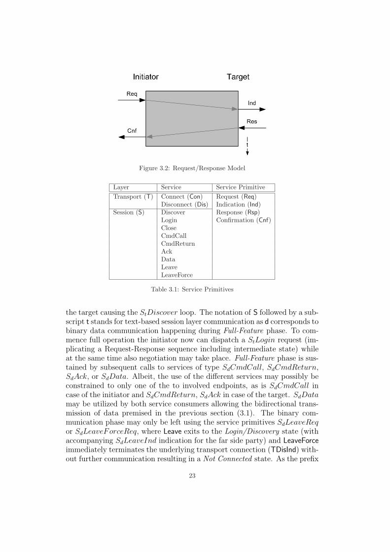
Figure 3.2: Request/Response Model
Layer Service Service PrimitiveTransport (T) Connect (Con) Request (Req)
Disconnect (Dis) Indication (Ind)Session (S) Discover Response (Rsp)
Login Confirmation (Cnf)CloseCmdCallCmdReturnAckDataLeaveLeaveForce
Table 3.1: Service Primitives
the target causing the StDiscover loop. The notation of S followed by a sub-script t stands for text-based session layer communication as d corresponds tobinary data communication happening during Full-Feature phase. To com-mence full operation the initiator now can dispatch a StLogin request (im-plicating a Request-Response sequence including intermediate state) whileat the same time also negotiation may take place. Full-Feature phase is sus-tained by subsequent calls to services of type SdCmdCall, SdCmdReturn,SdAck, or SdData. Albeit, the use of the different services may possibly beconstrained to only one of the to involved endpoints, as is SdCmdCall incase of the initiator and SdCmdReturn, SdAck in case of the target. SdDatamay be utilized by both service consumers allowing the bidirectional trans-mission of data premised in the previous section (3.1). The binary com-munication phase may only be left using the service primitives SdLeaveReqor SdLeaveForceReq, where Leave exits to the Login/Discovery state (withaccompanying SdLeaveInd indication for the far side party) and LeaveForceimmediately terminates the underlying transport connection (TDisInd) with-out further communication resulting in a Not Connected state. As the prefix
23

Figure 3.3: Protocol State Machine
Sd indicates the Leave service is not communicated by a text-based request inFull-Feature phase, but by a binary command packet. A valid session alwaysends in the Not Connected start/end state implying an eventual StCloseReqrequest (in case the Full-Feature phase has been left using the SdLeaveReqservice primitive).
Text-Phase Protocol
The text-based protocol messages consist of an input string which may notexceed a length of 4096 bytes while every character is of 8 bits in size withonly the lower 7 bits of the ASCII code (0–127) in use. Incompliant charac-ters should be avoided as the protocol behavior when processing this datais not defined. Due to the fact that the input string length is unknown atthe time when the initial connection is made the string has to be terminatedwith a well-known character sequence delimiting the transition from textto binary communication. Posing HTTP (HyperText Transfer Protocol)as example for a standardized Internet protocol the protocol to be designed
24

adopts the empty line delimiter (\n\n) also facilitating access to the protocolfor a console user (e.g., via telnet). The common format for data exchangeover the text-phase protocol is a ”<Property>: <Value>” sequence of lines(separated by \n characters). The occurrence of at least one property/valuetuple determining the service primitive to be invoked is mandatory. Thus, aminimal example for a valid text-phase message turns out to be of the form:
Primitive: LoginReq\n\n
Figure 3.4: Minimal Message (example StLoginReq)
Apart from the ability to transmit other session-specific data this text-based message protocol is also extensible in terms of new functionality whichmight be introduced in newer versions of this protocol. For example, theproperty/value format allows negotiation of additional features where theinitiator sends a login request, which contains a property enumerating fea-tures it is capable to support. The target compares this list with its owncapabilities and returns the intersection of the two sets in the subsequentlogin response.
Initiator
Primitive: LoginReqInitiator: de.jbls.clientCapabilities: multi -path , v2Isid: 1 # Initiator Session IDDevice: cdrw , 2:1User: jlieder # User NameSecret: ***** # Password Protection (opt)# Requesting access to device(s) 2:1 and cdrw.
Target
Primitive: LoginResTarget: de.jbls.storageCapabilities: multi -path # Confirming multi -path capTsid: 1 # Target Session IDUsid: 65537 # Unique Session ID# Granting access to atp ://de.jbls.storage ,cdrw.# Granting access to atp ://de.jbls.storage ,2:1.# Switching to Full -Feature mode ... you may proceed.
Figure 3.5: Sample Negotiation
The previous example (fig. 3.5) shows a sample conversation betweeninitiator and target during login-phase negotiating different parameters for
25

the establishment of a new session. Endpoint names do appear in reversedFQDN (Fully Qualified Domain Name) notation; that is inversed DNS orderwith TLD (Top Level Domain) to host name from left to right. This ismostly equivalent to the iSCSI convention (see RFC 3720, [11], 3.2.6. iSCSINames) where the name has to fulfill the requirements for Uniform ResourceNames (URN). Hence, the proposal for a general format of ATP-URIs (ASPITunnelling Protocol Uniform Resource Identifier) is:
atp://<tld.dns.rev>,<alias or remote HA:ID>
The reversed DNS notation provides a unique qualifier (at least in thelocal network) and also allows further indirection by a discovery server orservice. Another approach of consolidation could be multi-naming by theDNS naming service which resolves multiple Resource Names (URNs) to thetarget’s IP-Address. The target finally provides the appropriate resource byevaluating a passed ”Target:” property (comparable to the Virtual Hostfeature of modern HTTP servers). Nevertheless, in the local network thetarget name ”workstation” (no dots) simply remains ”workstation”.
In addition to the already mentioned negotiation of a common set of ca-pabilities a Unique Session ID (USID) is determined (calculated from theinitiator’s and target’s local SID). This ID allows the identification of asession which is necessary when implementing advanced functionality. Forinstance, the presented software architecture will be prepared for techniqueslike Multi-Threading and Multi-Path I/O (which potentially dependson such a SID mechanism) intended to be discussed among other designdecisions in the following implementation design chapter. However, actualspecification of a full set of allowed session negotiation properties is beyondthe scope of this protocol definition. The only specified properties are listedin table 3.2 where ”I” means the property has to be used in a text-phase re-quest. An ”O” property has an analogous meaning for the according response.Thus, referring to the aforementioned example (fig. 3.5) the Primitive prop-erty appears in both the login request and the subsequent login response.Finally, ”N” stands for negotiation (ranging across a request/response con-versation and implying the previously defined negotiation algorithm) of thecorresponding property.
Property TypePrimitive I/OCapabilities N
I: Request PropertyO: Response PropertyN: Request/Response
Negotiable Property
Table 3.2: Property Types
26

Full-Feature Phase Protocol
Unlike examined in the previous paragraphs the following section elaboratesa protocol definition for the opposing full-feature phase binary protocol.Thus, these protocols have to be considered completely independent from adesign point of view. Like any other protocol tier the session layer packetformat has to encapsulate payload data given in form of SDUs (Service DataUnits) from superior tiers. This encapsulation has to be accomplished byinitializing in-memory structures comprising preceding header and optionalsucceeding trailer structures, representing the actual PDU (Protocol DataUnit), which then can be passed to the underlying layer. Actually, themain task for the session layer, namely the correct initiation completed dur-ing text-phase and termination of logical sessions completed by a particulartype of data packet (containing a LEAVE command code), is realized. Apartfrom this primarily session-specific functionality the session layer also in-troduces the smallest communication unit in form of a well-defined packetformat. In consequence, this can be visualized as a resulting stream of con-tinuous session layer packets travelling along the transport connection. Asthe transmission of data in binary mode is also of sequential nature similarproblems as in case of the text-based protocol in terms of unknown messagelength emerge. A basic view of the packet header is shown in figure 3.6.
Figure 3.6: Session Layer Packet (Generic Layout)
The session layer packet header comprises several fields including datafor protocol-related communication and members increasing protocol ro-bustness. First, a valid packet begins with the magic sequence of 4 bytescontaining hex value 0x51 (which is equivalent to the ASCII string "QQQQ").Through the usage of a magic packet header it is likely to detect any pro-tocol mismatch or protocol violation during communication. The next fieldholds the length of the entire packet (4 bytes, unsigned integer) that is to beprocessed. As per specification every packet has to have a length multiple of64 bytes. Thus, the minimum packet size equals to 64 bytes where unusedsections in the payload field should be padded with zeros to reach the ap-propriate size. This restriction, however, involves some advantages for thesoftware implementation as in the situation of processing the first packet itis legal to receive a block of 64 bytes while the actual length of the packet isstill unknown. A continuous stream of this length guarantees the presenceof the full header allowing magic and packet length field to be extractedfor sanity check. The overhead introduced by the ”modulo 64” stipulation
27

should neither state a problem for the upper layers (as padding and un-padding happens transparently) nor for the underlying layers where oftenthe physical layer finally has to perform some kind of padding (e.g., GigabitEthernet, due to very short timings in conjunction with collision detection).Nevertheless, this might introduce a marginally increased message latency.The third field (again 4 bytes, unsigned integer) contains a sequence num-ber which will be monotonically increased on both the initiator and target,allowing a mechanism to continuously verify packet order (or detect poten-tial packet loss of unreliable transport connections). The last header fieldcomprises four single byte members, where the first two members specify thecommand TYPE and SUBTYPE transported by the corresponding packet. Allvalid combinations of TYPE and SUBTYPE constants are listed in table 3.3.
TYPE SUBTYPE COMMAND0x00 0x00 INVALID
0x01 NOP0x02 ECHO
0x01 0x00 INVALID0x01 CMD CALL0x02 CMD RETURN
0x02 0x00 DATA0x03 0x00 ACK0x04 0x00 RETR0xFF 0x00 INVALID
0x01 LEAVE0x02 LEAVE FORCE
Table 3.3: Command Constants
Further, SUBTYPE is followed by a reserved field (set to 0x00) and a FLAGS
field (each 1 byte in size), which contains contextual information for the ses-sion layer in form of two bits FLAGS FINAL (0x01) and FLAGS CONTD (0x02).These flags are mutually exclusive as FLAGS CONTD indicates that a packetis to be ”CONTINUED” (unless marked ”FINAL”); that is, subsequent packetshave to be processed to receive all information needed to build a completeupper layer packet. The residual bits of the FLAGS field are reserved forfuture use and should be set to zero.
Apart from a preceding header the session layer packet format also spec-ifies a trailer containing two additional fields. Both, the first reserved field(always equal to zero) and the second CRC field are 4 bytes in size. Thelatter member should assure the packet header’s integrity by calculating acorresponding Cyclic Redundancy Check value. However, a particular CRCor hash function will not be specified by this protocol proposal as long asthe algorithm is deterministic in terms of repeatability (viz. the opposingsession layer protocol instances have to be able to generate and verify the
28

hash value). Unless necessary (e.g., in case the underlying transport layerguarantees data integrity) an error check might also be omitted by usinga constant value verification (for example a bit-field equivalent to 0x8181).In summary, session layer header and trailer exhibit a combined length (oroverhead) of 24 bytes. Therefore, while generally not being constrained inlength a minimal session layer packet (64 bytes) may carry a payload of 0through 40 bytes.
Sync-Points
Like iSCSI the ASPI Tunnelling Protocol is designed to support Sync-Points(see [11], RFC 3720, 3.2.8 Fixed Interval Markers (FIM)). These Sync-Pointsare inserted into the session layer communication stream at fixed intervalswhere pointer values determine the start of the next packet. The insertion ofthese markers can be accomplished transparently to the remaining softwarelayers and represents an advanced mechanism to overcome TCP’s latency-related drawbacks (in situations of packet loss when out-of-order frames aretemporarily stored in buffers at transport layer level). The Sync-Point inter-val might be negotiated during the login phase, whereas a value of zero meansthe omission of these markers. Assuming a collision- and routing-free localnetwork, the following solution will not implement sync-points, therefore be-having like an extended ATP implementation with a negotiated sync-pointinterval of zero (proposed text-phase property: ”Interval: 1000”).
Tunnel Layer
The tunnel layer packet layout is quite similar to the session layer formatpreviously discussed. A magic header field for identification purposes is notnecessary so the first field is a tunnel layer related sequence number followedby fields containing the payload length and the payload offset. The lattershould always yield a value of 0x08 as only another reserved field (4 bytesagain holding a zero value) joins counting from the start of the same fielduntil the end of the reserved field. The offset value should be fixed for all32-bit and 64-bit architectures (in terms of memory layout) and might serveas check in case of a new protocol version where additional header fieldscould have been introduced. Thus, by skipping these extensible fields aswell as having direct access to the encapsulated payload (by the use of thispointer and the corresponding length) a certain version independence alsocould be realized. The tunnel layer packet format also includes a trailerwhich is identical to the session layer trailer except for the semantics of thechecksum field. Unlike the header, this checksum value references to thehandled payload. In other words, it protects the encapsulated data. Thus,along with session layer error check mechanism integrity of packet traffic
29

and the application-originated payload data may be presumed. In additionto yet another encapsulation the tunnel layer also transparently introducesapplication-specific semantics by segmenting and reassembling the logicalunit of SCSI Request Block (SRB) and its optional data buffer. The tunnellayer decides whether the data buffer has to be transmitted depending on thetype of command being dispatched. It might not be necessary to transportthe receiving data buffer to the command’s target when a Non-Data (N) orREAD command (R) is pending to be executed, and vice versa (for WRITE
commands (W)). The abbreviations refer to the common notion used in [5],p. 16.
Figure 3.7: Segmentation/Reassembly
In summary, for every command at least one tunnel layer (and there-fore one session layer) layer packet is generated. If the transmission of anaccompanying data block is required a second tunnel layer packet will beconstructed carrying the same tunnel layer sequence number (indicating al-legiance to to the same application layer command). These two packets inturn will be handed over to the session layer where again two session layerpackets of type CMD CALL (or CMD RETURN/ACK) and DATA are generated ac-tually containing the application-level payload.
In contrast to the standards discussed earlier (FC, iSCSI and SAS), allimplementing a mechanism (Ready2Transmit or equivalent) to avoid trans-mission of unsolicited data, the ASPI Tunnelling Protocol hands the re-sponsibility to determine the necessity for buffer data transmission to thecorresponding initiator. Even though this implies the requirement for largebuffers (as stated in [5], p. 28), for ATP, however, there is no unsoliciteddata. Thus, it is appropriate to avoid an additional R2T mechanism (whichactually means transmission of an intermediate notification command) po-tentially causing increased latency for the eventual command execution. Infact, if indicated by the initiator the buffer is prerequisite for proper execu-tion.
Finally, the thin application layer (see section 3.1) handles additionalmanagement tasks (including integrated logic to assert local memory co-herency as will be discussed in the subsequent section) and finally pro-
30

Figure 3.8: Layer 6 Packet (Generic Layout)
vides an adequate programming interface (API) for both the initiator andthe target. In case of the initiator this is a function set equivalent toSendASPI32Command() and GetASPI32SupportInfo(). For the target acallback function, which will be invoked upon command arrival is required.
3.3 Implementation Design
Similar to the protocol design procedure the implementation design willalso be developed in a bottom-up approach. Thus, beginning with the low-est software layer means the development of a Network Abstraction Layer(NAL) which can help in the attempt to abstract from various O/S-specificpeculiarities. This might also facilitate a cleaner design for the remaininglayers building upon this abstraction framework. As prominent examplethe Microsoft Windows operating system with its superseding WinSock API(see chapter 2.1.3) may be mentioned. While preserving the defined classinterface the underlying network stack may be exchanged (for example bydefining platform-dependent preprocessor symbols). The same applies tofuture technologies like IPv6 (see [3]) which should be taken into accountright from the early stages of design.
These objectives are achieved by introducing the class hierarchy of CGen-ericEndpoint (as abstract base class) stipulating the generic interface, andCTransportEndpoint, which finally implements the corresponding function-ality. The term ”Generic” as element of a class name suggests the abstractnature of this class as can be seen in the case of the given example. Thefollowing descriptive texts (particularly in this section) will be aligned withthe notions and peculiarities of the C/C++ language since the presentedsolution has been realized with this programming language, as well as theterm layer will be primarily used in the meaning of software layer, unlessotherwise noted.
The lowest layer of abstraction, namely CGenericEndpoint, is imple-mented in Network.cpp and defined in the corresponding header file Net-work.h. Generally, CGenericEndpoint (and the later CTransportEndpoint)are designed to provide an encapsulation for socket handles and the func-tion set operating on these handles (e.g., connect(), send(), and recv()).Apart from this set of functions, yet defined purely virtual, this abstract class
31

implements three static functions responsible for name and service resolution(tasks which are independent from particular socket handles). Further, Net-work.h introduces infrastructure needed for Internet Protocol (IP) versionindependence (for example, the use of struct in addr/sockaddr in ver-sus struct in6 addr/sockaddr in6). With the definition of a preproces-sor symbol IPV6 this software layer can be switched completely to IPv6support while also remaining compatible to compilation under Unix oper-ating systems. IPv6 support can be determined at runtime by evaluatingthe static variable CGenericEndpoint::s bIpVer6. For the Windows plat-form WsaTakeCare() takes care of the timely initialization and finalizationof WinSock library (by keeping account of the existing CGenericEndpoint
objects). The transport layer (Transport.cpp) builds on the given infrastruc-ture and implements the residual functionality with CTransportEndpoint
(namely all common socket functions). The class is independent from a par-ticular transport protocol (TCP/UDP are supported) and allows the reg-istration of a callback handler (RegisterAcceptHandler()), which will beinvoked on connection request (this only applies to an endpoint operating inserver-mode). As with connection acceptance the requesting peer’s addressis also passed, a mechanism for address or network-based connection filteringcan be implemented (see the later implementation of the application-leveltarget class).
This also leads to a design issue, yet to be encountered, which actu-ally concerns the application-level objects rather than the current topic oflow-level transport endpoints. However, from a software design point ofview, unfortunately, initiator and target classes cannot be architected sym-metrically in their use of transport protocol endpoints objects. While thehigh-level initiator can delegate the creation of a transport connection tothe lower layers that are actually responsible for this task, in a top-downapproach the opposing application-level target object has to create its ownlistening transport-layer endpoint (the creation takes place within the ap-plication layer). On the event of accepting a new connection the newlyacquired endpoint object (or socket handle) has to be published to the un-derlying layers upon construction, resulting in an iterative hand-over of thishandle down to the lowest layer.
However, with the implementation of Network.cpp and Transport.cpp thefunctionality of ISO/OSI layers 1 through 4 is adapted and available asfoundation the remaining software, namely the adjacent session layer, canbe built on. This will be subject of the next paragraphs.
The session layer class CGenericSession introduces the basic frameworkfor the entire session layer functionality. That is, the assignment of sessionendpoint roles (session initiator or target), a session state and the corre-sponding state machine, and an interface for sending and receiving text-
32

Figure 3.9: Transport Endpoint Classes
phase messages as well as full-feature phase packets. However, due to theabstract nature of this class (see CGenericEndpoint) the actual function-ality has to be implemented by an inherited class. This, in turn, increasesflexibility for the software solution to incorporate or realize different tech-niques (i.e., various differently powerful classes). Along with these particularconsiderations one might also anticipate the potential benefit in conjunctionwith the previously discussed negotiation mechanism. A fact, which willbe important for the constitutive architecture as the software should be de-signed to support Multi-Path I/O (see section 3.2), which is a technique todeploy multiple transport connections at a low level by reasons of increasedresilience and throughput. By locating this functionality in a preferably lowsoftware layer (obviously the session layer) the upper layers can be insulatedfrom these peculiarities. The first incarnation of the code will only realize asingle-pathed nexus yet maintaining an augmented code infrastructure readyfor advanced features. Here the notion of a nexus refers to the logical con-nection between initiator and target, which (in case of an multi-path nexus)might accommodate multiple paths. Thus, a path forms the smallest logicalunit of communication (in this case simply a transport layer connection).In summary, the superior session class delegates the eventual task of packettransmission to the associated classes (visualized by the UML associationbetween the involved classes, see fig. 3.10). When there should be usedmultiple paths the responsible session class (CMultiPathSession) creates anexus capable of managing such a facility (CMultiPathNexus). This multi-path nexus finally sets up the required communication paths (likely a pri-mary communication path also responsible for management tasks which thenmight negotiate the further installation of simple paths (CSimplePath)).Nevertheless, this functionality still belongs to (and happens within) the
33

session layer and does not represent a violation of the layered paradigm.From a session’s point of view these late connections implicate continuingissues when connecting with the target. This fact also influenced some designdecisions. As already mentioned in the preceding section a clean softwaredesign had to be abandoned due to the need for a central management of theserver socket. This now comes into play when considering a situation wheremultiple sessions have to co-exist while still having to be ready to acceptfurther connection request. The scenario gets even worse for the creationof multiple paths since the corresponding session object has no authorityto control the serving connection endpoint. Thus, if the affected sessionwould maintain its own transport endpoint – in addition to the actual ser-vice socket – to allow authoritative path management, new dynamic serviceport numbers had to be communicated. Since the set of port numbers fora service should be predictable, this dynamic (and protocol-specific) portbehavior renders the service impractical when being deployed in firewalledscenarios. However, the primary argument against this approach is finallythe fact that distinct session instances should not be aware of their sib-ling instances by design. The disadvantage of the proposed solution is thereversed assignment of responsibility for the target class hierarchy wherethe application-level object becomes the connection principal (in contrastto the initiator where the responsibility for transport connection is assignedto the lowest session layer), which leads to this asymmetrical design. Stillthe possibility for the application-layer (AL) target to distinguish betweenthe established sessions has to be given, realized by the already introducedSession ID (SID). In other words, the SID defines the session allegiance for anew path connection. Thus, prior to the assignment of a new path the peerhas to perform a text-based conversation with the AL-Target which thendelegates the current transport endpoint to the responsible session object(by using the submitted SID). The delegation takes place by passing theendpoint object to the constructor of the corresponding child object. Bothdiscussed scenarios should be roughly visualized by figure 3.11.
In case of the session classes (CGenericSession/CSinglePathSession)there are three types of members functions:
nexus management EstablishNexus(), CloseNexus()text-phase protocol SendText()/ReceiveText() and
SendLoginRequest()/ReceiveLoginResponse()full-feature phase SendPacket()/ReceivePacket() andcommunication NoOperationCommand()/LeaveCommand()
Most part of the session layer (fig. 3.11) should be considered as frame-work and abstraction for the support of multiple communication paths, yetthe code responsible for tunnelling comprises the most important function-
34
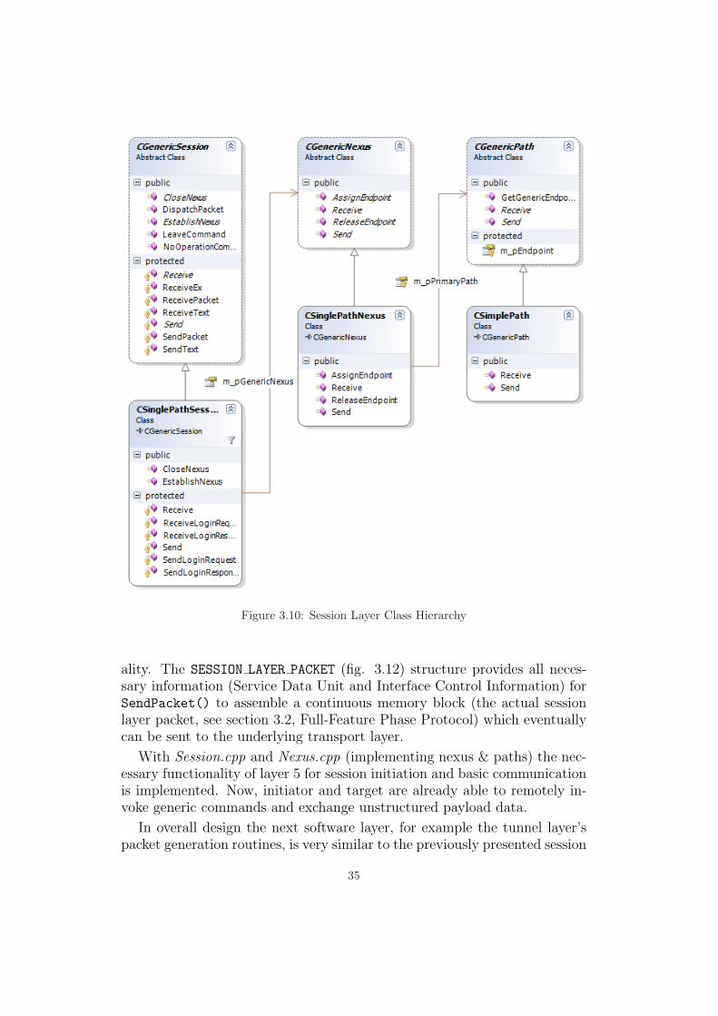
Figure 3.10: Session Layer Class Hierarchy
ality. The SESSION LAYER PACKET (fig. 3.12) structure provides all neces-sary information (Service Data Unit and Interface Control Information) forSendPacket() to assemble a continuous memory block (the actual sessionlayer packet, see section 3.2, Full-Feature Phase Protocol) which eventuallycan be sent to the underlying transport layer.
With Session.cpp and Nexus.cpp (implementing nexus & paths) the nec-essary functionality of layer 5 for session initiation and basic communicationis implemented. Now, initiator and target are already able to remotely in-voke generic commands and exchange unstructured payload data.
In overall design the next software layer, for example the tunnel layer’spacket generation routines, is very similar to the previously presented session
35
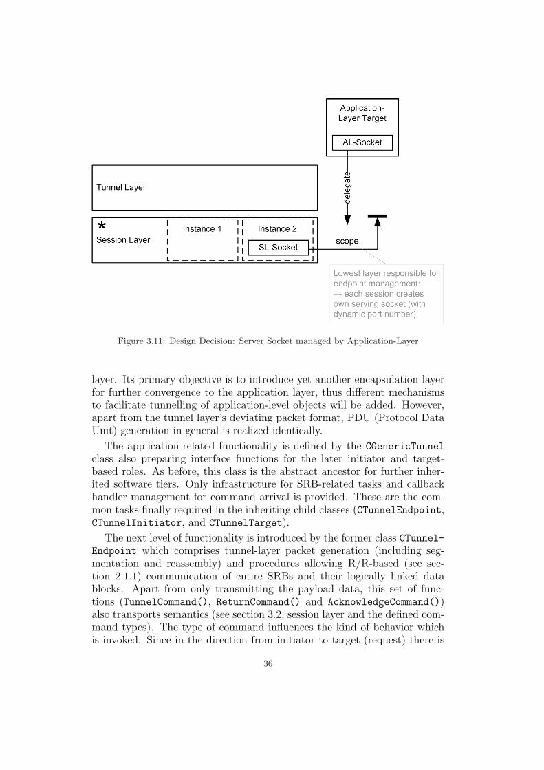
Figure 3.11: Design Decision: Server Socket managed by Application-Layer
layer. Its primary objective is to introduce yet another encapsulation layerfor further convergence to the application layer, thus different mechanismsto facilitate tunnelling of application-level objects will be added. However,apart from the tunnel layer’s deviating packet format, PDU (Protocol DataUnit) generation in general is realized identically.
The application-related functionality is defined by the CGenericTunnel
class also preparing interface functions for the later initiator and target-based roles. As before, this class is the abstract ancestor for further inher-ited software tiers. Only infrastructure for SRB-related tasks and callbackhandler management for command arrival is provided. These are the com-mon tasks finally required in the inheriting child classes (CTunnelEndpoint,CTunnelInitiator, and CTunnelTarget).
The next level of functionality is introduced by the former class CTunnel-Endpoint which comprises tunnel-layer packet generation (including seg-mentation and reassembly) and procedures allowing R/R-based (see sec-tion 2.1.1) communication of entire SRBs and their logically linked datablocks. Apart from only transmitting the payload data, this set of func-tions (TunnelCommand(), ReturnCommand() and AcknowledgeCommand())also transports semantics (see section 3.2, session layer and the defined com-mand types). The type of command influences the kind of behavior whichis invoked. Since in the direction from initiator to target (request) there is
36

enum SESSION_LAYER_PCI_TYPE{
slInvalid ,slNoOperation ,slCommand ,slDataSegment ,slAcknowledge ,slRetransmit ,slLeave
};
struct SESSION_LAYER_PCI{
SESSION_LAYER_PCI_TYPE spciType;
BYTE bySubType;
BOOL bContinued;BOOL bFinal;
};
struct SESSION_LAYER_PACKET{
UPPER_LAYER_PACKET *pBottomPdu;
SESSION_LAYER_PCI spciControlInfo;UPPER_LAYER_PACKET ulTunnelPdu;
};
Figure 3.12: Session Layer Protocol Interface
only the CMD CALL primitive (dispatched by TunnelCommand()), as responsethe two primitives CMD RETURN/ACK (dispatched by ReturnCommand() andAcknowledgeCommand(), respecitvely) are valid. The exact communicationmodel for the different types of implementation will be discussed in the sub-sequent sections. Nevertheless, the tunnel endpoint class is also responsiblefor transparent transmission of SRBs; that, is coherency between the SRB’sdata buffer pointer and the actual location of its buffer (the target uses localtemporary buffers) has to be maintained.
As already mentioned in section 3.2 probably two session layer PDUshave to be generated for a single SRB to be tunnelled. Nevertheless, sincethe session layer builds on transport layer functionality, there is no maxi-mum transfer size limitation and thus no need for any kind of fragmentation.This also applies to the generation of tunnel layer PDUs and the correspond-ing SDUs (namely, application layer SRB and data buffers). Finally, this
37
means the responsible tunnel layer may simply generate two packets andpass them to the underlying layer, if the layer’s remote instance guaranteesreassembly of both PDUs to a valid SRB. This behavior requires additionalfunctionality in the CTunnelEndpoint class which is implemented by theUpdateSrb() function taking care of correct updates to a SRB memorystructure. These updates to in-memory SRBs represent a critical task asthe contained pointers are only valid in the local domain of the executingmachine. Generally, a SRB and a data buffer are unrelated, unless the SRBpoints to this data buffer prior to execution. On a remote computer the vir-tual memory layout may look completely different requiring the correctionof all data buffer pointers. However, the additional effort confines to theprocessing of EXEC SCSI CMD request blocks (since only these SRBs containpointers). Another high level task for the tunnel layer is the maintenance ofsequence numbers which depend on the client application’s dispatch order.Especially for a multi-threaded implementation sequence numbers are im-portant as ordered queues have to be processed and acknowledgements mayarrive out of order.
The next level of inheritance is realized by the classes CTunnelInitiatorand CTunnelTarget, which customize the generic behavior (of CTunnel-
Endpoint) for the initiator and target roles of the ATP protocol. By us-ing inheritance it is possible for the child classes to override the introducedcommon functionality. For example DispatchCommands() has been imple-mented in CTunnelEndpoint realizing a dispatch loop for arriving tunnellayer packets by continuously calling DispatchCommand() (until a sessionlayer LEAVE command is encountered). By overriding DispatchCommand()
within CTunnelInitiator and CTunnelTarget, the target is able to ade-quately process CMD CALL packets and the initiator may react on CMD RETURN
and ACK messages. The exact implementation of these two classes deter-mines whether the later ATP initiator or target will act synchronously orasynchronously. In the next two sections this will be discussed in moredetail.
The final software layer is the application layer. As announced in section3.1 this layer will be relatively thin. Actually, the involved classes (in Ap-plication.cpp) do not participate in the previous class hierarchy, but they dorely on the accumulated functionality of the ATP protocol stack by creatinginstances of CTunnelInitiator and CTunnelTarget, respectively.
The main assignment for an application layer initiator class is the provi-sion of a standard ASPI programming interface (SendASPI32Command() andGetASPI32SupportInfo()) which then can be used in client applications totransparently include ASPI services or to export via DLL (Dynamic LinkLibrary). Since the CTunnelInitiator class already implements most of therequired functionality the CAtpInitiator class remains relatively compact.
38

While not being included in the current implementation the class shouldalso be responsible for providing a virtual Host Bus Adapter (which allowsaccess to a set of ATP tunnels leading to different targets/target devices)and accordingly loading an adequate configuration on initialization.
In contrast to the initiator CAtpTarget maintains connection manage-ment. On the event when a client connects to the server socket the ATP tar-get class hands over the new connection to a dynamically created CTunnel-
Target object. Before application layer communications may commenceCAtpTarget also registers a default SRB handler function with the tunneltarget class. This callback function (DefaultSrbHandler) is a static mem-ber function of CAtpTarget and acts as default implementation which simplydispatches the incoming SRB requests to the target’s local WinASPI layerfor actual execution.
For a comprehensive overview one may find a complete UML diagramin Appendix A including the entire ATP class hierarchy. It might help insurveying the solution’s principal structure and design outlined in the pastchapter. A valuable hint for easier understanding might be the recognitionof associations as links between protocol layers/software sub-layers.
3.4 Synchronous Implementation
A synchronous software implementation is characterized by its proceduraldesign. At runtime it is possible to exactly determine the algorithm’s nextinternal state if the previous state was also known. Hence, both endpointsbehave as deterministic automatons realizing a strict horizontal commu-nication protocol which under no circumstances may be violated (in con-trast to the later asynchronous implementation where these commitmentswill be relaxed by a certain degree). The actual communication sequenceof the synchronous implementation is shown in figure 3.13. Referring toprevious considerations (see chapter 1) a basic R/R-model has to be re-alized resulting in two distinct states receiving and sending, an endpointmay assume. Due to the asynchronous nature of some ASPI function calls(deferred completion notification) this fact has to be regarded when de-signing the protocol communication sequence. In the first step (1) theinitiator tunnels a SRB by invoking TunnelCommand() (which maps to aCMD CALL packet on session layer) while the target is in receiving mode.The target knows (by specification) that a single tunnel layer PDU ar-rives and executes the ASPI command after the corresponding SRB hasbeen placed properly into memory (2). When regaining program controlfrom the WinASPI layer the target changes to sending mode (3) and dis-patches a ReturnCommand() to notify the receiving initiator about this event
39

as soon as possible (since ReturnCommand() also submits the target’s up-dated SRB memory structure the initiator may evaluate the return sta-tus of SendASPI32Command()). If the issued ASPI command behaves asyn-chronously (see Tunnel.cpp, CGenericTunnel::IsAsyncSrb(LPSRB)) the tar-get has to check for SRB completion which depends on notification methodpreviously passed in the SRB Flags field. However, some of these flags willbe masked out to determine a common notification mechanism on the targetside (preferably the Windows Event Notification API (SRB EVENT NOTIFY)for low CPU overhead, see [2], p. 31). If the SRB status already is not equalto SS PENDING (see [2], p. 34) the command is completed or has failed. Oth-erwise the process ceases operation cooperatively until completion by callingthe Windows API WaitForSingleObject(). Although rendering this im-plementation suboptimal an AcknowledgeCommand PDU is sent (4) even if asynchronous SRB has been transmitted. The initiator in turn waits for bothmessages and modifies the local memory facilitating a transparent ASPIlayer emulation for the client application. The client may (legally) poll theSRB’s status field for completion or error code. The downside of this ap-proach is the inability to process multiple SRBs in parallel which might bedesirable for increased-demand scenarios. Additionally, supplemental CPUresources in form of multiple system cores cannot be used since all activitytakes place in a single thread within a process.
Figure 3.13: Synchronous Implementation: Sequence Diagram
The source of a synchronous implementation is not provided with this so-lution as the approach only marks an intermediate state of the work. Variousmodifications had to be applied to the code to allow multi-threaded opera-tion and improvements have only been incorporated into the later code base,thus both implementations might be recognized as independent branches ofthe solution. However, finally it should be easy to build an advanced syn-chronous implementation drawing benefits from the results of this work and
40
building on the presented ASPI Tunnelling Protocol stack and infrastruc-ture.
3.5 Asynchronous Implementation
For the intention to implement asynchronous protocol instances additionalcode infrastructure has to be at the programmer’s disposal since constructsto protect critical code sections are essential in multi-threaded program-ming. Furthermore, different kinds of queues acting as input and outputmechanisms between dependent threads will be needed. The most promi-nent types are the FIFO (first-in first-out) queue and especially in commu-nications software the priority heap for tasks like packet reordering. Mostof these ADTs (Abstract Data Types) provided by standard programminglibraries (e.g., Standard Template Library, STL) are not re-entrant andthus not applicable to multi-threaded programs. As the presented solu-tion will utilize the validated STL classes queue and priority queue toavoid errors being potentially introduced by custom code, the ATDs haveto be enveloped by classes responsible for adequate locking. Functionslike Enqueue() and Dequeue() have to be of atomic nature. This mightalso apply to operations on numeric values implying the need for inter-locked variable classes. The source file Queue.cpp and its header aggregatethis functionality by implementing CGenericQueue, CSimpleQueue (encap-sulates std::queue), and CSyncQueue. The priority heap is implementedby CPriorityQueue (using an instance of std::priority queue) and syn-chronized by CSyncPrioQueue. Finally, the last type of ADT is realizedby CBoundedBuffer<TYPE> (inherits from CTypedPtrArray<CPtrArray,TYPE>, provided by Microsoft Foundation Classes (MFC)). The boundedbuffer provides a number of slots in which incoming acknowledgements fromthe target can be arranged. Like previously visualized by template notation,all classes are templated and thus type-independent (as usually demandedfrom ADTs). Another important class is CSignal which facilitates signalingof events between threads by using the Windows Event Notification API.Hence, instances of CSignal (containing a Windows event handle) can alsobe used for convenience on the initiator to notify the client application ofcommand completion (ASPI layer emulation) and completion tasks on thetarget (see previous section).
Multi-threaded design primarily affects the lowest sub-tier of the tunnellayer, namely the classes CTunnelInitiator and CTunnelTarget. In theformer class two queues (m psqSendQueue, m psqSentQueue) and a boundedbuffer (m psbPendingBuffer) are introduced. With a client application dis-patching a SendASPI32Command() function call the accompanying SRB isenqueued in the Send Queue. There are also three types of threads complet-
41
ing different tasks. The Transmit Thread continuously dequeues elementsfrom the Send Queue for transmission over the ATP tunnel. After tunnellingthe SRB is categorized as sent by adding the address of the SRB to the SentQueue. However, prior to the blocking transmission the thread has to checkwhether the Sent Queue may accept another element. Otherwise it is blockeduntil an element gets freed (by using three interleaved critical section locksas internal signalling mechanism, see producer/consumer problem). This isthe sequential behavior referred to in section 2.1.3. The blocking ensuresthat when the SRB should be inserted into the Bounded Buffer simultane-ously (the buffer is accessed by increasing sequence numbers) already usedslots will not be overridden. The bounded buffer is necessary for rapid accessto pending SRBs when an acknowledgement comes in (the queue does notand must not provide random access) and since the buffer does not possessfurther access control facilities this might cause loss of data. It is just theReceive Thread which is responsible for the access to pending SRBs and theirupdate (according to the received data). Finally, completed SRBs have to bedisposed sequentially by the Dispatch Thread ; that is, only the head of theSent Queue is examined. By peeking the queue’s first element (the thread isblocked if the queue is empty) the current sequence number is determined.This sequence number defines the slot in the bounded buffer where the ac-tual state information is stored. A state value of qssGarbage indicates thatsignalling and freeing of memory structures have occurred. This behaviorinduces the existence of potential head-of-queue issues during the process ofdisposal, however, due to the fixed maximum number of pending SRBs thisbehavior is explicitly desired. Nevertheless, disposal is independent fromsignaling (which happens in the Receiver Thread), thus from the client’sperspective all ASPI tasks are still completed asynchronously (as indicatedby the target).
For an asynchronously working target different considerations have to bemade. As the initiator may employ more than just one Transmit Thread,theoretically consecutively enqueued SRBs might arrive at the target out oftheir order. Further, the target also is not restricted in its number of ReceiveThreads. To ensure correct re-ordering of the arriving SRBs the target im-plements a priority queue (m pqSrbQueue of type CSyncPrioQueue<CPrio-QueuedSrb *>). All incoming SRBs are enqueued while the element withthe highest priority, that is the earliest SRB, resides on top of the heap.The priority heap does not deal with the omission of sequence numbers,thus the target additionally maintains a sequence number for the next com-mand pending to be issued. As long as the next command is not received(the top element of the heap does not carry the pending sequence number) allWorker Threads are blocked. The blocking is realized by a signalling mech-anism which reacts to the arrival of new elements. As previously hinted
42

multiple Worker Threads may exist while the number of threads determinesthe amount of concurrently executing ASPI commands. Each thread pro-cesses an ASPI command and is responsible for its further observation; thatis, returning the return result back to the initiator, waiting for the executionto be completed, and the eventual acknowledgement of the command (seefigure 3.14). Subsequent to this process the thread may assume responsibil-ity for a new ASPI command.
Keeping advanced functionality like Multi-Path I/O in mind, the exis-tence of multiple Transmit and Receive Threads matches exquisitely to theconcept of multiple communication paths. Here, each thread is associatedwith a previously established path: upon creation each threads receives apointer to its associated path which the thread in turn uses as ICI (Inter-face Control Information) for the function call when dispatching a tunnellayer packet. The information is passed by each layer until the nexus finallydelivers the session layer packet to the responsible path object. Parts ofthis behavior (see Session.h, CMultiPathSession::Send(PCBUFFER pData,
int nLength, SESSION PCI pPci)) are already implemented yet redirect-ing all requests to the (single) primary path of a multi path nexus. Insummary, for the initiator this means for each path there must exist a trans-mitting and a receiving thread (2n + 1, whereas n is the number of paths).The target has to employ a receiving thread for each utilized path and anarbitrary number of worker threads (n + m, whereas m is the number ofconcurrent ASPI tasks). For a single path nexus these requirements areoptional; that is, the target may keep the 5 threads especially for use withSMP (Symmetric Multi-Processing) systems.
The existing code base is written in C++ for compilation with the Mi-crosoft product line of C++ compilers. Initial development was started withthe MS Visual C++ 6.0 (SP6) IDE and therefore should be still compati-ble with this environment. However, development was shifted to MS VisualStudio .NET 2003 and finally MS Visual Studio 2005 during the overallprocess. This is why the focus did not remain on backwards compatibilityto VC6 and it might be necessary to modify some portions of the code torecover compatibility. Further, the presented code should be considered ex-perimental with the primary objective to demonstrate feasibility of the givenspecifications, yet an application among end-user systems nearly might beimaginable. Especially multi-threaded programming is error-prone and sev-eral bugs are likely to be eliminated yet.
43

Figure
3.14:A
synchronousIm
plementation:
Com
prehensiveD
esignD
iagram
44

Chapter 4
Evaluation
4.1 Synchronous Implementation
The initial synchronous implementation has not been extensively analyzedduring development. While these implementations already worked (all im-portant types of SRBs were transmitted correctly), they caused high CPUloads due to the utilization of polling (busy waiting) for command com-pletion. Debugging was conducted with a client and a server application(SockClient and SockServer) acting as simple initiator and target. Here,SockClient comprises test code which performs a device discovery resultingin a listing of devices found on the remote system (see figure 4.1). On theother hand, SockServer realizes a simple target allowing the connection to asingle initiator. Incoming SRBs are forwarded to the local Windows ASPIlayer for execution. Later versions of SockServer implemented Event Noti-fication which has a diminishing effect on the excessive usage of resources.To allow further testing the current code base was incorporated into a newproject which should yield a Windows ASPI layer (Wnaspi32.dll) replace-ment library. However, this implementation remained synchronous. Theresults indicated relatively moderate performance, yet the first endeavor oferasing and burning a CD-RW medium over network connection succeeded.Further, Nero 6 Reloaded performed as ASPI client application.
Despite working properly, throughout this thesis performance will bebenchmarked by regarding the absence of Buffer Underruns (BURN) at dif-ferent data rates (i.e., recording speed). Variable buffer fill levels are strictlyconsidered unacceptable, even though todays recording devices are able toavoid corruption of media during these underrun situations. However, it isnot desirable to tolerate BURNs, as a frequent buffer refill generally pro-longs the burning process (with rising BURN count elapsing time increasesexceedingly).
45

Date: Wed Dec 14 21:58:52 2005Target Name: chiefTarget Port: 8181Target Alias: aliasHost adapter inquiry succeeded.
Manager: <NERO ASPI32 >Identifier: <atapi >Device: NEC CD -ROM DRIVE :463Device: MEGARAID LD 0 RAID 0
Figure 4.1: Console Output: Device Listing (SockClient)
Hardware ConfigurationPentium 4 1.6 GHz256 MB RIMM100 MBit/s Realtek NICPentium III 600 MHz320 MB DIMMIntel PRO/100 NICO/S: Windows XPCross-Connected CAT5
Experimental ResultsRec. Speed Data Rate Device Buffer4x: 600 KiB/s 1.788 MiB/s 80%8x: 1200 KiB/s 1.311-2.980 MiB/s < 60%10x: 1500 KiB/s peak 4.410 MiB/s not stable
Table 4.1: First Performance Results
Figure 4.1 shows the impact of the initial implementation’s triple payloadtransmission. Thus, the collected measurements range between two andthree times the actual recording speed. Stable results (relatively constantbuffer fill level of 80%) were only observed with 4x (600 KiB/s) recordingspeed, although an optimization has been deployed causing the omissionof CMD RETURN messages (the initiator waits until the target sends the finalcommand completion acknowledgement). Speeds of 8x or even 10x yieldedno stable results, hence the imprecise data rates.
4.2 Asynchronous Implementation
The SockClient source code could virtually remain unmodified, since theATP interface for initiators (with the usual ASPI interface function setof SendASPI32Command() and GetASPI32SupportInfo()) was not touched.However, the actual implementation of the ATP protocol stack changed dra-matically (see section 3.5). Also new code dispatching multiple SRBs in par-allel to test the new implementation’s capabilities was introduced. Here itis important that the initiator side of protocol correctly signals completionwith event notifications. Further, various problems with thread synchro-
46

nization occurred and compatibility to Nero had to be reconstituted. TheSocketServer, on the other hand, was now able to accept multiple clientconnections accomplished by a dedicated server socket Accept Thread. EachATP tunnel also employs multiple Receiver and Worker Threads again per-mitting asynchronous operation at this level. For evaluation purposes thetarget’s DefaultSrbHandler() dumps the current state of the internal SRBqueue as shown in figure 4.2.
[106038585] Queue Size 1, Async SRBs pending 0
Figure 4.2: Console Output: Queue Size (SockServer)
Having SockClient and SockServer approved to work correctly with thenew implementation, it is of great interest whether the ASPI wrapper (Wn-aspi32.dll) can also be suited to the new code and more importantly theyields over the former realization that might be expected. Unfortunately,the status printed by SockServer (figure 4.2) while operating together withNero Burning Rom as initiator showed a low utilization of available queuecapacity. To be more accurate, the maximum queue size was a single pendingelement (as shown in figure 4.2). This means, albeit Nero is programmedas a multi-threaded application, the main thread responsible for dispatchingcommands to the ASPI layer does not fully use its asynchronous feature set.Thus, Nero does also not make use of the queued services provided by ATP-MT (the multi-threaded implementation of the ASPI Tunnelling Protocol).That means even during a burning process always only a data block of 64KiB is in flight. Nevertheless, eventually data is buffered by the target’srecording device providing reliability for the overall process.
To achieve the prescribed objective of actual user-friendliness and easydeployment, another project is included with the solution. AtpTarget is aWindows Service which comprises the ATP implementation and additionalinfrastructure for service management (e.g., command line options to installand uninstall the service on a Windows machine; sufficient administrativerights presumed). A Windows Service can be run with SYSTEM accountpermissions without needing a user to be logged onto the machine. In thefollowing section this ATP Target Service is consulted for all further mea-surements (see Appendix D).
4.3 Experimental Results
The asynchronous implementation of ASPI Tunnelling Protocol initiator andtarget has been thoroughly tested in the following environment (see fig.4.2). As previously hinted, for the target role a properly installed AtpTargetWindows Service in conjunction with the Nero ASPI Layer (version 2.0.1.74)
47

has been employed. Nero Burning Rom 6 Reloaded (version 6.6.0.18) actedas client application for the latest Wnaspi32.dll ATP initiator.
The environment comprised two dedicated target and initiator machines(hardware configuration see below) running a copy of Windows Server 2003SP1 and Windows XP SP2, respectively.
Target Initiator NetworkAMD Duron 700 MHz AMD Athlon 1333 MHz Gigabit Ethernet Switch512 MB 512 MB 16 Gbps BackplaneIntel GbE PRO/1000MT Intel GbE PRO/1000MT 1.4881 Mpps per PortPlextor PX-W4012AWindows Server 2003 EE Windows XPService Pack 1, Build 3790 Service Pack 2
Table 4.2: Hardware Setup
To determine network performance a network latency measurement hasbeen conducted by using the traceroute utility. Traceroute can be in-structed to either use ICMP ECHO or UDP packets for operation and withthe -q option a certain number of packets can be sent. With the deter-mination of average round-trip time (RTTs) network performance can beestimated. For network layer ECHO packets (38 bytes) the average RTT is0.171 ms (171 µs) and for 128 byte transport layer UDP packets the aver-age delay is 0.365 ms (365 µs). To be able to comprehend these values theconsole output is listed in figure 4.3.
$ traceroute stef.jl.pa23.net -I -q 20traceroute to stef.jl.pa23.net (192.168.8.3), 30 hops max,38 byte packets1 stef.jl.pa23.net (192.168.8.3)0.386 ms 0.269 ms 0.153 ms 0.152 ms 0.179 ms 0.170 ms 0.164 ms0.151 ms 0.152 ms 0.152 ms 0.148 ms 0.150 ms 0.151 ms 0.152 ms0.145 ms 0.150 ms 0.149 ms 0.147 ms 0.147 ms 0.150 ms
Figure 4.3: Latency Measurements
With this configuration the highest possible (yet stable) speed could beascertained to 2,400 KiB/s. Since the applied hardware environment canbe regarded as average equipment, generally, viable burning speed with thecurrent ATP implementation was ultimately limited to 16x CD.
To further analyze the performance of the implementation in conjunc-tion with the hardware environment Ethereal as Network Protocol Analyzerhas been deployed. Prior to use possible TCP Offload Engines (TOEs)should be deactivated through the driver software, as this causes the ana-lyzer software to mark most frames (Ethernet and TCP segments) due to
48

invalid CRC values. These calculations are offloaded from the TCP stackand not made until the NIC dispatches the Ethernet frame. The analyzerrunning on the initiator machine captured an excerpt from a ATP sessionbeing busy of recording a CD. With the recorded dump the exact timingof the transmitted Ethernet frames and the corresponding TCP segmentscould be determined. Here, communication showed large delays in messageresponse that were caused unlikely by the processing on the target computer.The conclusion should be that the receiver is not able to process the dataimmediately. This adverse timing just coincided with the TCP segmentswhich were not marked with the TCP PUSH flag. The PUSH flag is locatedin the TCP header of each segment and instructs the remote TCP stack toimmediately pass the incoming data to the corresponding application pro-cess. However, the occasional absence of PUSH flags should be traced backto Nagle’s Algorithm (1984) [9] described in RFC 896. At that time, graveproblems arose due to limited bandwidth and the excessive transmissionof small packets (for example caused by usage of telnet) causing conges-tion collapse. Nagle’s proposal was to retain small packets on the sender’sside if acknowledgements are still outstanding. This behavior matches wellwith the previously observed timing issues. From a programmer’s point ofview it is not possible to influence TCP flag generation directly, but theappliance of Nagle’s Algorithm (which is deployed in virtually every modernTCP/IP implementation) can be easily deactivated. This is done by apply-ing a setsockopt() function call to the corresponding socket handle. SocketAPI documentation disadvises the usage of the TCP NODELAY socket optionwith the constraint the option yet might be applicable to code which has tosend many small messages. For this implementation the TCP NODELAY op-tion means the emulation of a datagram-like service (implicating small delay)over an established stream-oriented TCP connection. In other words, whensending a large chunk of data or a small message on the application layer,the last TCP segment (carrying the PSH flag) is sent immediately and thuscannot cause a delay any more. To realize the modified behavior the existingsource files can easily be patched, whereas in Nexus.cpp the member functionCSinglePathNexus::AssignEndpoint(CGenericEndpoint *pEndpoint) islocated allowing the change to be applied to the initiator, target, and evenall involved path endpoints. The additional code is shown in figure 4.4. Justin proximity to this modification the final code of Nexus.cpp also adjuststhe TCP receive and send windows (SO RCVBUF and SO SNDBUF options) tofurther optimize the stack behavior. These new options, however, are not oftransport layer level but of socket level (modifying the socket operation).
When reviewing the Linux iSCSI implementation (hosted on Source-Forge.net) it is not long until stumbling upon the code section where theTCP NODELAY option is activated there (linux-iscsi/daemon/iscsi-io.c, line 79).
49

101 int flag = TRUE;102103 CTransportEndpoint *pTranspEndp =104 dynamic_cast <CTransportEndpoint *>(pEndpoint );105106 _ASSERTE(pTranspEndp );107 BOOL bSuccess = pTranspEndp ->SetSockOpt(108 TCP_NODELAY , &flag , sizeof(flag), IPPROTO_TCP109 );
Figure 4.4: Application of the TCP NODELAY Option
In other words, the TCP NODELAY option is an indispensable prerequisite forcommunication protocols like iSCSI and ATP (as of equal nature). A shortEthereal dump of this datagram communication between TCP NODELAY ini-tiator and target on the data link layer (Ethernet) is shown in Appendix C.In addition to this dump Appendix C also includes a listing of the ATP con-nection establishment phase on transport level (hex dump of conversation).
With the new code the former issue is resolved and in the given configu-ration ATP now is able to operate with data rates up to 40x CD speed andyet no indication for symptoms of too high demand. Further, this perfor-mance seems to be relatively insensible against additional traffic (i.e., a filecopy process on a network share), since switched networks should be ideallycollision-free (no retransmits). Indeed, data rates of 6,000 KiB/s are quitenear the theoretically possible bandwidth of Fast Ethernet (100 MBit/s)networks.
The diagram in figure 4.5 shows the reached data rates and the usertime CPU utilization (pure user level overhead) of the ATP target during a40x CD (6,000 KiB/s) speed test run. The attached Plextor recording devicepractices ZoneCLV with distinct zones of constant burning speed (the drive’smotor is adjusted to maintain speed while otherwise the actual write speedwould continuously increase), which can be easily observed in the diagram.The user time (in percent) alone is utilized by the AtpTarget process onthe machine. With increasing write speed the moderate CPU utilizationis slightly rising. When only accounting active periods the average usertime is about 6%. This can also be put into relation with the average datarate of the corresponding zone which results in a value of 1.50% user timeCPU utilization per processed MiB/s. While being acceptable for averagecomputers, certainly, this amount of overhead can still be optimized.
With the knowledge about feasibility of various burning speeds in thegiven environment the observed behavior can be mathematically analyzed.The following formulas will calculate bandwidth and latency requirements
50
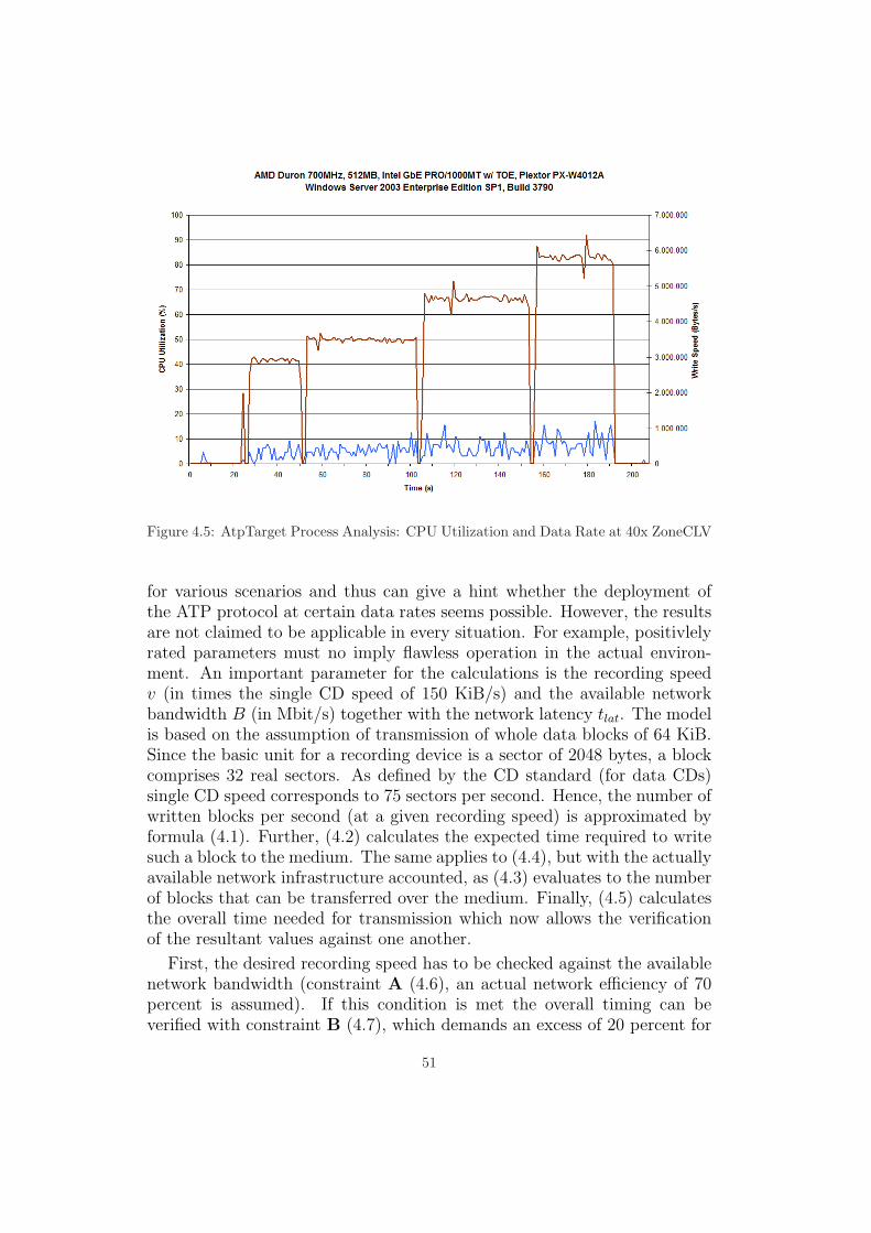
Figure 4.5: AtpTarget Process Analysis: CPU Utilization and Data Rate at 40x ZoneCLV
for various scenarios and thus can give a hint whether the deployment ofthe ATP protocol at certain data rates seems possible. However, the resultsare not claimed to be applicable in every situation. For example, positivlelyrated parameters must no imply flawless operation in the actual environ-ment. An important parameter for the calculations is the recording speedv (in times the single CD speed of 150 KiB/s) and the available networkbandwidth B (in Mbit/s) together with the network latency tlat. The modelis based on the assumption of transmission of whole data blocks of 64 KiB.Since the basic unit for a recording device is a sector of 2048 bytes, a blockcomprises 32 real sectors. As defined by the CD standard (for data CDs)single CD speed corresponds to 75 sectors per second. Hence, the number ofwritten blocks per second (at a given recording speed) is approximated byformula (4.1). Further, (4.2) calculates the expected time required to writesuch a block to the medium. The same applies to (4.4), but with the actuallyavailable network infrastructure accounted, as (4.3) evaluates to the numberof blocks that can be transferred over the medium. Finally, (4.5) calculatesthe overall time needed for transmission which now allows the verificationof the resultant values against one another.
First, the desired recording speed has to be checked against the availablenetwork bandwidth (constraint A (4.6), an actual network efficiency of 70percent is assumed). If this condition is met the overall timing can beverified with constraint B (4.7), which demands an excess of 20 percent for
51

the calculated timing requirements.
v = recording speed [x CD]B = network bandwidth [MBit/s]tlat = network latency [ms]
1x CD = 150 KiB/s1 Block = 64 KiB
Formulae
a =⌈
7532 · v
⌉(4.1)
treq =1
a · 1000(4.2)
b =⌊B · 1000 · 1000
8 · 64 · 1024
⌋(4.3)
ttrans =1
b · 1000(4.4)
t = 2 · ttrans + tlat (4.5)
Constraints
B >v · 150 · 102470% · 125000
(4.6)
t < 80% · treq (4.7)
For the given experimental setup (v = 40, B = 1000, tlat = 1) the resultis an overall block transmission time of t = 2.52 milliseconds. Apart fromthe fact that the Gigabit Ethernet definitively is capable of sustaining theassigned data rate, this is well below the required timing of treq = 10.64 ms(which corresponds to 94 Blocks per second). Even with a Fast Ethernetnetwork as interconnect (B = 100) formula (4.5) returns a feasible value of
52

t = 7.26 ms.
Of different concern is the implicated CPU utilization during operation onthe target (and also the initiator). With the previously determined value of1.50 percent utilization per MiB/s data rate the impact can be extrapolatedfor other CPU speeds (same architecture and linear scaling assumed).
U = 1.5 · v · 150
1024· 700
f(4.8)
This represents a very imprecise estimation where U means the resul-tant utilization and f the actual processor speed in megahertz. User timeutilization also implies consumption of privileged time (geater or equal, atleast). Hence, 50 percent CPU utilization should be considered as satura-tion for the processor. Nevertheless, while being potentially inaccurate theestimation might give a hint to minimum CPU requirements at a definedrecording speed v. For the present 40x (6,000 KiB/s) the lower limit seemsto be reached at some 133 MHz.
Similar tests have been conducted with the same target but a differentinitiator machine (Intel Pentium III 600 MHz, 320 MB RAM, 100 MBitNIC). By experiment, a maximum recording speed of 24x was identified.According to the previous calculations (p. 52) the timing requirements aremet, but continuous buffer underrun conditions occurred. Due to the obser-vation of relatively high CPU utilization during the test it seems likely to bethe reason of failure. Probably additional aspects remained unconsidered inthe presented set of formulas.
Finally, it might be interesting to analyze the limits of the solution ofthis thesis by exchanging the underlying physical network with a wirelesstechnology. Here, latency is the predominant limitation as air is a sharedmedium which has to be arbitrated. Unfortunately, for testing only 802.11bWLAN equipment was available, which is not even capable of providing therequired (transport layer) data rate for the lowest possible recording speedof 4x (600 KiB/s). In a real world scenario the WLAN link (11 MBit/s)yields a data rate of approximately 350 KiB/s, a fact that inevitably leadsto buffer underruns when serving as network infrastructure for an ATP tun-nel. However, despite suffering inherently from latency issues, a WirelessLAN with adequate bandwidth seems to be capable, as buffer underrunswere moderate during the tests. Experiments generally acknowledging fea-sibility of ATP over WLAN might be of further interest. Even tests over aWAN (Wide Area Network) connection were successful. While the processof erasing a rewritable medium (CD-RW) only produces few and infrequentcommands, this experiment confirmed the possibility to even use an Internetconnection with the ATP protocol.
53

54

Chapter 5
Analysis
The following chapter will analyze the collected results and discuss variousother aspects concerning the so far presented solution of this thesis. Apartfrom the many advantages and downsides associated with the given solution,it may be referred to as correct. In addition to the careful design processthe actual proof of correctness is done by the observation of overall correctoperation in normal and experimental application.
However, correctness is not sufficient in real-world scenarios as for theend-user the primary concern is reliable operation and performance of thesolution. Depending on the given network infrastructure this objective isaccomplished, viz. data rate and latency requirements at the applicationlevel are met. Last but not least, this is significantly facilitated by the usageof the TCP NODELAY option.
5.1 ASPI over IP
As demonstrated up to this point, with the developed solution it is possibleto tunnel application-level ASPI SRBs over a network interconnect. TheASPI Tunnelling Protocol (ATP) has been designed just for this purposeand realizes all specified requirements, as it actually facilitates the tunnellingof ASPI commands. Tasks like maintaining distributed memory coherency(chapter 1) and many others being associated with the primary objectiverequire careful design (with several accompanying decisions of importance)and a rather complex framework of supporting functionality.
Beginning with a layered solution paradigm and after having previouslystudied SCSI, ASPI, and network fundamentals the design was being elabo-rated by a bottom-up approach. The protocol design included the definitionof an appropriate state machine and was followed by the formulation of atext-phase and finally a full-feature phase protocol. This part of the pro-
55

tocol demanded the definition of a session layer and a tunnel layer packetformat. With the Implementation Design part and in particular the more de-tailed sections Synchronous Implementation and Asynchronous Implemen-tation the actually realized design decisions were outlined (Appendix B.1includes a detailed diagram of the layered overall architecture, p. 65). Thesubsequent chapter delved into the experimental analysis of the developedASPI Tunnelling Protocol and shows the limitations of the solution imposedby external conditions. Nevertheless, the experimental analysis facilitatedthe revelation of a software-related issue which could be identified and copedwith.
However, with the experiences gained over the course of this thesis ithas to be noticed that even while ASPI provides the functionality to lever-age multi-threaded operation, it is barely utilized by client applications (aslearned with the example of Nero). From a system architectural point ofview the multi-threaded design of an appropriate solution seems to be worth-while, yet for future work it might be reasonable to rather focus on a lesssophisticated single-threaded solution based on the insights of this thesisand the provided implementation. Since that would be sufficient, at leastfor the initiator part, inherent sources of bugs in the residual code couldbe eliminated. Some of the potential possibilities will be elaborated in thesubsequent section.
5.2 Advantages/Drawbacks (ATP)
The software architecture for the entire ASPI Tunnelling Protocol stack hasbeen thoroughly designed. The goal of a good design should finally be therealization of a straightforward and elegant implementation, however, it isimpossible to prevent a project from growing and thus with the experiencegained during implementation, it certainly would have been possible to cor-rect some of the formerly committed programming flaws. Some of the mosturging issues will be discussed in the following Outstanding Issues section.Multi-Threaded programming and especially debugging is complex, a factthat actually limited the amount of revision the code could obtain in thecourse of this study thesis. In any case, the result can be regarded as proof-of-concept.
Further, a strictly scientific design process sometimes involves an enlargedor even bloated OOP (Object Oriented Programming) hierarchy. Often thesame functionality might be accomplished with procedural programming andfewer resources. A prominent example can be found with the class compoundof CGenericSession, CGenericNexus, and CGenericPath. Inheritance isthe appropriate procedure to aggregate functionality, however, the same in-
56

heritance complicates debugging due to large call stacks and causes overheadat runtime. Certainly the ATP protocol could be redesigned to flatten theclass hierarchy with a low-level implementation of a single software layer.Probably two software layers (session and tunnel layer) might not be neces-sary. Nevertheless, in case of features like Multi-Path I/O (MPIO) the cleansoftware design of the existing class hierarchy still can ease programmabil-ity and despite the previous considerations a great deal of work and carefulthought went into the layout of particular classes and functions.
Obviously, the advanced features mentioned throughout this work likeMulti-Threading and Multi-Path I/O are aimed at the operation withNero Burning Rom (in increased-demand scenarios). With multi-threadingfinally realized and a class hierarchy prepared for operation in multi-pathmode, it is unfortunate that these features can only be utilized by softwarewhich by itself is of multi-threaded nature and prepared to asynchronouslywait for multiple commands to complete. The multi-pathing feature readiesthe ATP protocol for resilience and the benefit of multiple links betweeninitiator and target allowing the utilization of additional bandwidth. Other-wise throughput and latency would be limited by a single network adapterin the single-threaded case. Anyway, systems with multiple cores (togetherwith SMP) seem to become more common in future, even for the averagehome user and thus multi-threading still remains an interesting aspect forthe overall system architecture. In summary, it is hardly possible to antic-ipate Nero’s low requirements in terms of multi-thread awareness prior tohaving realized an actually multi-threaded implementation.
5.3 Outstanding Issues
As previously announced in 5.1 this section will discuss some possible im-provements for the existing code base towards an optimized and reliablesoftware solution which can be deployed among a production environment.First, a technique called Scatter/Gather I/O (SGIO) should be applied in thecode; that is, a vector of blocks (comprising pointer and the block’s length)is passed to a vectorized version of a function. SGIO is used in several placesof an operating system, however, for this solution the vectorized versions ofSocket API functions, namely sendv() and recvv(), are important. Similarfunctions are also provided by the WinSock API. While optimizing programefficiency SGIO can also simplify packet assembly as scattered data does nothave to be copied into a contiguous chunk of memory. For example, headerpart, payload data, and packet trailer may reside at different locations whichmight (1) avoid the allocation of memory (new) and the (2) accompanyingcopy operations (memcpy()).
57

252 PBUFFER pBuffer = new BUFFER[ulPacketLength ];253 TUNNEL_HEADER *pHeader = (TUNNEL_HEADER *) pBuffer;254255 PBUFFER pPayloadBuffer = (PBUFFER) (pHeader + 1);256257 memcpy(pPayloadBuffer , pcUpperLayerPacketBuffer ,258 ulUpperLayerPacketLength );
Figure 5.1: Packet Generation Code (Session.cpp)
Together with the generation of packet checksums these tasks cause themost processing overhead of the protocol stack. However, the well separatedstructure of Network Abstraction Layer (NAL) and its adjacent softwarelayers should constrain the effort needed for the integration of a SGIO-enabled interface (i.e., verctorized function signatures). The realization al-ready would decrease required resources, but a methodology for passing anordered list of packet fragments between protocol layers has to be intro-duced. Such an abstracted data structure is a common obstacle in layeredprotocol programming hence several approaches can be found among in-ternal operating system designs. An elegant way to overcome the problemis given with Windows’ paradigm of I/O Request Packets (IRPs) appliedwithin the Windows driver stack [8]. The IRP provides a common structureenabling each driver located in the stack to access driver-specific (or layer-specific) information. This design could also be applied to the existing ATPimplementation and facilitate (vertical) inter-layer protocol communication.Another important issue in conjunction with internal stack communicationis freeing of previously allocated memory which could also be simplified bythe use of a data structure equivalent to IRPs. The problem is caused bythe asymmetric behavior of the sending and receiving protocol instances.In the former case the memory allocation originates in the highest protocollayer (a SendPacket() request) and deallocation has to happen after thePDU has actually been dispatched on the lowest layer. In the contrary caseof the opposing protocol instance, the initial packet originates in the lowestprotocol layer where memory has to be allocated on packet arrival. Therequired memory cannot be freed until the PDU has been processed by theentire protocol stack demanding a separate packet processing behavior forthe two occurrences of protocol endpoints. Again, a common data struc-ture facilitating internal protocol communication and carrying all importantinformation for the separate protocol layers could ease the task of keepingaccount of allocated memory blocks (memory leaks).
With today’s network hardware (high bandwidth, low latency) it is pos-sible to realize the presented solution of the ATP protocol. Even the serial
58

network technology is able to provide latencies which are adequate for de-manding tasks like the transmission of storage subsystem traffic, at leastfor high level (application layer) protocols like ATP or iSCSI. This trafficcannot be compared to the raw SCSI communication over an interconnectbus or point-to-point connection. Here, with these specialized interconnecttechnologies the demands to the timing behavior are much more restrictive.The performance gains accomplished by the TCP NODELAY modifications pro-vide some headroom for the increasing data rates reached with the currentgeneration of CD/DVD recorders. However, due to restrictions caused bynetwork or computer hardware with limited resources, it might be necessaryto discover new possibilities to decrease latency requirements or further op-timizations of the ASPI Tunnelling Protocol. A potential tweak to diminishrelevancy of protocol message delay might be the premature acknowledge-ment of pending requests to the client software. This application then maydispatch further WRITE commands although the former SRBs are still aboutto be processed on the target. This, in turn, demands an mechanism todetect unexpected conditions in case of an error during execution. However,the SCSI standard already defines two mechanisms in conjunction with thisbehavior. It is explicitly legal to acknowledge WRITE commands with a GOOD
status while the request is buffered in the drive’s cache unless the so calledForce Unit Access (FUA) bit is set ([15], p. 131). In this case, subsequentcommands are obligated to indicate a Deferred Error Condition ([16], 4.5.5,p. 39). Fortunately, Nero omits the FUA bit to leverage the drives’ buffer-ing features, which also supports the possible application of this tweak infuture implementations of the ASPI Tunnelling Protocol. In other words,the immediate acknowledgement is likely to provide a mechanism to be-come virtually independent from latency issues while the single limitationof sufficient bandwidth between initiator and target remains.
Apart from this set of internal optimizations some external improvementscould also be made. The following considerations suggest completion of apurely multi-threaded implementation or an advanced single-threaded incar-nation of the protocol initiator. Certainly, the MT version would be moreversatile, however, due to the lack of support ST would be sufficient evenfor the use with Nero Burning Rom. Since the advanced ST solution onlycomprises a single main program thread it would be rendered almost un-able to implement features like Multi-Path I/O. As discussed above, packetgeneration overhead could be easily diminished by the presented mecha-nisms, yet the single-threaded initiator should allow the application clientto use the Windows event signaling system to further optimize the usageof CPU resources. Anyway, sources for bugs could be eliminated with theless complex single-thread solution, which might be the primary objectivefor eventual deployment among end user computers. In either case, the tar-
59

get’s implementation should remain multi-threaded, as for the server sideasynchronous execution might be of foremost concern.
In summary, the core of the presented ATP protocol stack may remain toprovide a reliable framework for future software utilizing the ASPI Tun-nelling Protocol. Nevertheless, some additional proposals for these im-plementations should be mentioned. First, the concept of a Virtual HostAdapter (VHA) could be enforced by the protocol initiator. This VHA thencould realize an abstraction for the management of multiple sessions to differ-ent target computers. Here, a mapping between virtual devices and sessionhas to be established. Since the transmission of SRBs is transparent betweeninitiator and target the common device addresses (HA:ID) are derived fromthe target’s local device map. This means all initiators have to support adevice address mapping from virtual addresses to target addresses, whilethe target controls access to unlocked devices for the corresponding session.Prior to initialization of the local ATP ASPI Layer the user should be ableto modify the association of Virtual Devices (VD) (to the VHA) which thencan be used in the following Nero session. If configuration changes are notlikely to happen frequently, it is also imaginable to provide access to theconfiguration in form of a Windows Control Panel applet. In figure 5.2 asuggestion for an appropriate UI is visualized.
Figure 5.2: Association Dialog UI Proposal
60

Chapter 6
Conclusion
To conclude the work of this study thesis presented in the course of theprevious five chapters, the following paragraphs will finally give a repetitiveoverview. The impetus for the given topic, ASPI over IP, was the observa-tion of an apparent lack of support for optical devices as rather importantform of mass storage in the case of already existing solutions facilitatingseparation of storage devices from the responsible host system. It is obviousthat this concept in general is applicable to various scenarios and thus hasbeen subject of recent research and commercial interest. A fact also outlinedby the sheer number of different standards (amongst others, there are forexample the most important occurrences of Fibre Channel and its siblingiSCSI), which were considered throughout the first part of this thesis.
The existing technologies allow the transparent transmission of SCSI com-mand traffic across almost any type of interconnect to achieve the objectiveof a distributed storage network and independence from local computer busesat the same time. By choosing this generic approach, namely tunnellingSCSI over serial network transports, a completely new level of storage virtu-alization is achieved. However, this type of virtualization has not yet beencarried to the domain of optical storage, its peculiar requirements, and therespective application software (at least in case of the Windows family ofoperating systems). Hence, an appropriate and equivalent solution (thatmeans taking a very similar approach to existing solutions) for the ASPIinterface, which represents an important standard for this type of applica-tion software, should be designed. While several methodologies and notionscould be adopted from the standards earlier studied, a new protocol withtext-based and full-feature phase had to be developed to facilitate the seman-tically correct transmission of SRBs. Having a functional ASPI tunnellingprotocol stack at hand, in the subsequent course of design two distinct re-alizations (single-threaded/synchronous and multi-threaded/asynchronous)were identified and also elaborated. An actual implementation in software
61

finally demonstrated the correctness of the presented solution also in itsmulti-threaded incarnation (initiator and target). Subsequently, varioustests with the final code base have been conducted in real-world scenar-ios (target computer equipped with recording device and initiator runningNero Burning Rom as client application). By identifying software-relatedissues obviously impeding network message timing, it became possible tofurther improve overall performance up to a level, which may well satisfythe requirements for most optical storage recording tasks.
Despite its preliminary status, the code base demonstrates feasibility ofthe approach and proper operation of the ATP communication protocol.At this point, together with some of the clues for further software designimprovements and the outlook to user interface optimizations identifiedthroughout the final part of this work, the conclusion of a viable solution tothe objective of this thesis can be drawn.
62

Appendix A
Class Hierarchy
63

Figure
A.1:
Com
prehensiveU
ML
Diagram
ofthe
AT
PC
lassH
ierarchy
64

Appendix B
Layered Architecture
Figure B.1: Detailed Diagram of the layered ATP Architecture
65

66

Appendix C
ASPI Tunnelling Protocol
67

10.000000
192.168.8.11
192.168.8.3
2227>8181
[SYN]
Seq=0
Ack=0
Win=65535
Len=0
MSS=1460
20.000113
192.168.8.3
192.168.8.11
8181>2227
[SYN,
ACK]
Seq=0
Ack=1
Win=16384
Len=0
MSS=1460
30.000034
192.168.8.11
192.168.8.3
2227>8181
[ACK]
Seq=1
Ack=1
Win=65535
Len=0
40.000198
192.168.8.11
192.168.8.3
2227>8181
[PSH,
ACK]
Seq=1
Ack=1
Win=65535
Len=21
50.000467
192.168.8.3
192.168.8.11
8181>2227
[PSH,
ACK]
Seq=1
Ack=22
Win=65514
Len=21
60.191807
192.168.8.11
192.168.8.3
2227>8181
[ACK]
Seq=22
Ack=22
Win=65514
Len=0
70.128133
192.168.8.11
192.168.8.3
2227>8181
[PSH,
ACK]
Seq=22
Ack=22
Win=65514
Len=128
80.000570
192.168.8.3
192.168.8.11
8181>2227
[PSH,
ACK]
Seq=22
Ack=150
Win=65386
Len=128
90.011079
192.168.8.11
192.168.8.3
2227>8181
[PSH,
ACK]
Seq=150
Ack=150
Win=65386
Len=128
10
0.000435
192.168.8.3
192.168.8.11
8181>2227
[PSH,
ACK]
Seq=150
Ack=278
Win=65258
Len=128
11
0.013139
192.168.8.11
192.168.8.3
2227>8181
[PSH,
ACK]
Seq=278
Ack=278
Win=65258
Len=128
12
0.000287
192.168.8.3
192.168.8.11
8181>2227
[PSH,
ACK]
Seq=278
Ack=406
Win=65130
Len=128
13
0.027535
192.168.8.11
192.168.8.3
2227>8181
[PSH,
ACK]
Seq=406
Ack=406
Win=65130
Len=192
14
0.169253
192.168.8.3
192.168.8.11
8181>2227
[ACK]
Seq=406
Ack=598
Win=64938
Len=0
15
0.000090
192.168.8.11
192.168.8.3
2227>8181
[PSH,
ACK]
Seq=598
Ack=406
Win=65130
Len=128
16
0.000452
192.168.8.3
192.168.8.11
8181>2227
[PSH,
ACK]
Seq=406
Ack=726
Win=64810
Len=192
17
0.149751
192.168.8.11
192.168.8.3
2227>8181
[ACK]
Seq=726
Ack=598
Win=64938
Len=0
18
0.000260
192.168.8.3
192.168.8.11
8181>2227
[PSH,
ACK]
Seq=598
Ack=726
Win=64810
Len=448
19
0.008737
192.168.8.11
192.168.8.3
2227>8181
[PSH,
ACK]
Seq=726
Ack=1046
Win=64490
Len=192
20
0.168798
192.168.8.3
192.168.8.11
8181>2227
[ACK]
Seq=1046
Ack=918
Win=64618
Len=0
21
0.000095
192.168.8.11
192.168.8.3
2227>8181
[PSH,
ACK]
Seq=918
Ack=1046
Win=64490
Len=128
22
0.000438
192.168.8.3
192.168.8.11
8181>2227
[PSH,
ACK]
Seq=1046
Ack=1046
Win=64490
Len=192
23
0.122146
192.168.8.11
192.168.8.3
2227>8181
[ACK]
Seq=1046
Ack=1238
Win=64298
Len=0
24
0.000247
192.168.8.3
192.168.8.11
8181>2227
[PSH,
ACK]
Seq=1238
Ack=1046
Win=64490
Len=448
25
0.002900
192.168.8.11
192.168.8.3
2227>8181
[PSH,
ACK]
Seq=1046
Ack=1686
Win=65535
Len=192
26
0.202279
192.168.8.3
192.168.8.11
8181>2227
[ACK]
Seq=1686
Ack=1238
Win=64298
Len=0
27
0.000085
192.168.8.11
192.168.8.3
2227>8181
[PSH,
ACK]
Seq=1238
Ack=1686
Win=65535
Len=128
28
0.000446
192.168.8.3
192.168.8.11
8181>2227
[PSH,
ACK]
Seq=1686
Ack=1366
Win=64170
Len=192
29
0.194568
192.168.8.11
192.168.8.3
2227>8181
[ACK]
Seq=1366
Ack=1878
Win=65343
Len=0
30
0.000261
192.168.8.3
192.168.8.11
8181>2227
[PSH,
ACK]
Seq=1878
Ack=1366
Win=64170
Len=448
31
0.003057
192.168.8.11
192.168.8.3
2227>8181
[PSH,
ACK]
Seq=1366
Ack=2326
Win=64895
Len=192
32
0.129667
192.168.8.3
192.168.8.11
8181>2227
[ACK]
Seq=2326
Ack=1558
Win=65535
Len=0
33
0.000095
192.168.8.11
192.168.8.3
2227>8181
[PSH,
ACK]
Seq=1558
Ack=2326
Win=64895
Len=128
34
0.000419
192.168.8.3
192.168.8.11
8181>2227
[PSH,
ACK]
Seq=2326
Ack=1686
Win=65407
Len=192
35
0.166930
192.168.8.11
192.168.8.3
2227>8181
[ACK]
Seq=1686
Ack=2518
Win=64703
Len=0
36
0.000265
192.168.8.3
192.168.8.11
8181>2227
[PSH,
ACK]
Seq=2518
Ack=1686
Win=65407
Len=448
37
0.002378
192.168.8.11
192.168.8.3
2227>8181
[PSH,
ACK]
Seq=1686
Ack=2966
Win=64255
Len=192
38
0.158045
192.168.8.3
192.168.8.11
8181>2227
[ACK]
Seq=2966
Ack=1878
Win=65215
Len=0
Figure
C.1:
Sample
AT
PC
onversation(E
therealD
ump)
68

>00000000
50
72
69
6d
69
74
69
76
65
3a
20
4c
6f
67
69
6e
Primitiv
e:
Login
>00000010
52
65
71
0a
0a
Req..
<00000000
50
72
69
6d
69
74
69
76
65
3a
20
4c
6f
67
69
6e
Primitiv
e:
Login
<00000010
52
65
73
0a
0a
Res..
>00000015
51
51
51
51
80
00
00
00
64
00
00
00
01
01
00
01
QQQQ....
d.......
>00000025
e8
03
00
00
3c
00
00
00
08
00
00
00
00
00
00
00
....<...
........
>00000035
00
00
01
00
00
00
00
00
00
00
00
00
00
00
00
00
........
........
>00000045
00
00
00
00
00
00
00
00
00
00
00
00
00
00
00
00
........
........
>00000055
00
00
00
00
00
00
00
00
00
00
00
00
00
00
00
00
........
........
>00000065
00
00
00
00
00
00
00
00
00
00
00
00
00
00
00
00
........
........
>00000075
30
01
00
00
00
00
00
00
00
00
00
00
00
00
00
00
0.......
........
>00000085
00
00
00
00
00
00
00
00
00
00
00
00
2b
02
00
00
........
....+...
<00000015
51
51
51
51
80
00
00
00
65
00
00
00
01
02
00
01
QQQQ....
e.......
<00000025
e8
03
00
00
3c
00
00
00
08
00
00
00
00
00
00
00
....<...
........
<00000035
00
01
01
00
00
00
00
00
03
ff
4e
45
52
4f
20
41
........
..NERO
A<
00000045
53
50
49
33
32
00
00
00
00
00
61
74
61
70
69
00
SPI32...
..atapi.
<00000055
00
00
00
00
00
00
00
00
00
00
00
00
02
08
00
00
........
........
<00000065
02
00
00
00
00
00
00
00
00
00
00
00
00
00
00
00
........
........
<00000075
c8
03
00
00
00
00
00
00
00
00
00
00
00
00
00
00
........
........
<00000085
00
00
00
00
00
00
00
00
00
00
00
00
2d
02
00
00
........
....-...
>00000095
51
51
51
51
80
00
00
00
66
00
00
00
01
01
00
01
QQQQ....
f.......
>000000A5
e9
03
00
00
3c
00
00
00
08
00
00
00
00
00
00
00
....<...
........
>000000B5
00
00
00
00
00
00
00
00
00
00
00
00
00
00
00
00
........
........
>000000C5
00
00
00
00
00
00
00
00
00
00
00
00
00
00
00
00
........
........
>000000D5
00
00
00
00
00
00
00
00
00
00
00
00
00
00
00
00
........
........
>000000E5
00
00
00
00
00
00
00
00
00
00
00
00
00
00
00
00
........
........
>000000F5
30
01
00
00
00
00
00
00
00
00
00
00
00
00
00
00
0.......
........
>00000105
00
00
00
00
00
00
00
00
00
00
00
00
2d
02
00
00
........
....-...
Fig
ure
C.2
:Sa
mpl
eA
TP
Con
vers
atio
n(T
rans
port
Lay
er)
69

70

Appendix D
ATP Target Service
Figure D.1: ATP Target implemented as native Windows Service
71

72
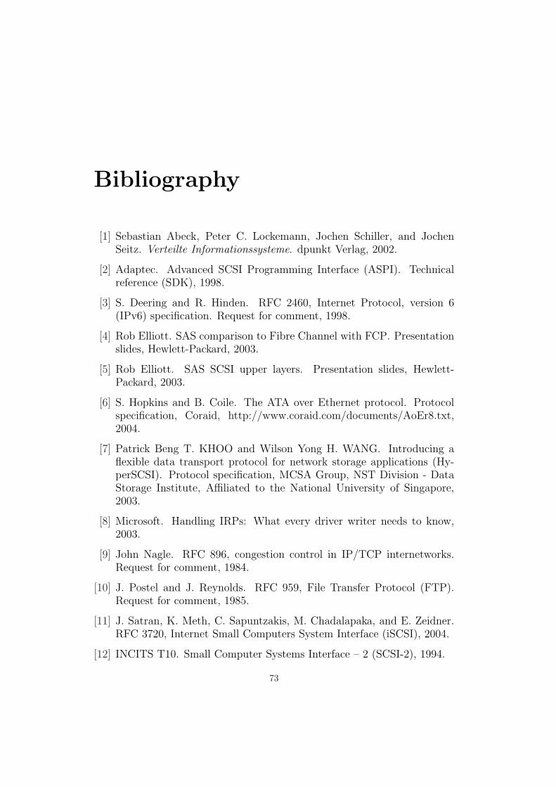
Bibliography
[1] Sebastian Abeck, Peter C. Lockemann, Jochen Schiller, and JochenSeitz. Verteilte Informationssysteme. dpunkt Verlag, 2002.
[2] Adaptec. Advanced SCSI Programming Interface (ASPI). Technicalreference (SDK), 1998.
[3] S. Deering and R. Hinden. RFC 2460, Internet Protocol, version 6(IPv6) specification. Request for comment, 1998.
[4] Rob Elliott. SAS comparison to Fibre Channel with FCP. Presentationslides, Hewlett-Packard, 2003.
[5] Rob Elliott. SAS SCSI upper layers. Presentation slides, Hewlett-Packard, 2003.
[6] S. Hopkins and B. Coile. The ATA over Ethernet protocol. Protocolspecification, Coraid, http://www.coraid.com/documents/AoEr8.txt,2004.
[7] Patrick Beng T. KHOO and Wilson Yong H. WANG. Introducing aflexible data transport protocol for network storage applications (Hy-perSCSI). Protocol specification, MCSA Group, NST Division - DataStorage Institute, Affiliated to the National University of Singapore,2003.
[8] Microsoft. Handling IRPs: What every driver writer needs to know,2003.
[9] John Nagle. RFC 896, congestion control in IP/TCP internetworks.Request for comment, 1984.
[10] J. Postel and J. Reynolds. RFC 959, File Transfer Protocol (FTP).Request for comment, 1985.
[11] J. Satran, K. Meth, C. Sapuntzakis, M. Chadalapaka, and E. Zeidner.RFC 3720, Internet Small Computers System Interface (iSCSI), 2004.
[12] INCITS T10. Small Computer Systems Interface – 2 (SCSI-2), 1994.
73

[13] INCITS T10. SCSI Architecture Model – 2 (SAM-2). Standards draft,2002.
[14] INCITS T10. SCSI RDMA Protocol (SRP). Standards draft, 2002.
[15] INCITS T10. Multimedia Commands – 5 (MMC-5). Standards draft,2005.
[16] INCITS T10. SCSI Primary Commands – 3 (SPC-3). Standards draft,2005.
[17] INCITS T13. AT Attachment – 5 with Packet Interface Draft (ATAPI-5), 2000.
[18] Fujita Tomonori and Ogawara Masanori. Performance of optimizedsoftware implementation of the iSCSI protocol. Technical report, NTTNetwork Innovation Laboratories, 2003.
74