schüco tip tronic – systemhandbuch¼co tip tronic – system handbook nutzungsbedingungen der...
TRANSCRIPT
Green Technology for the Blue PlanetClean Energy from Solar and Windows
Grüne Technologie für den Blauen PlanetenSaubere Energie aus Solar und Fenstern
Sch
üco
Tip
Tron
ic –
Sys
tem
hand
buch
Sch
üco
Tip
Tron
ic –
Sys
tem
han
dboo
k
Schüco Tip Tronic – Systemhandbuch Schüco Tip Tronic – System handbook
Nutzungsbedingungen der Schüco International KG für die Nutzung der Schüco-Kataloge (Kataloglizenz)
LizenzbedingungenDurch das Öffnen der Schutzhülle (Plastikfolie) vereinbart der Empfänger („Kunde“) des eingeschweißten Katalogs mit der Schüco International KG („Schüco“) die nachfolgenden Regelungen. Falls der Kunde diese Regelungen nicht anerkennen will, ist der eingeschweißte Katalog unge-öffnet zurückzugeben; eine Nutzung oder Weitergabe desselben ist dann nicht zu lässig. Schüco weist ausdrücklich darauf hin, dass die Abgabe von gedruckten Informationen in Bezug auf die von Schüco vertriebenen Produkte („Kataloge“) ausschließlich nach Abschluss und zu den Be-dingungen dieser Kataloglizenz vereinbarung zwischen dem Empfänger und Schüco erfolgt. Damit gelten zwischen dem die Kataloge und seine Inhalte nutzenden Kunden und Schüco die nachfolgenden Regelungen.Urheber- und NutzungsrechteDie Kataloge und die in ihnen enthaltenen Inhalte und Daten („Katalo-ginhalte“) sind rechtlich geschützt. Alle Rechte an den Kataloginhalten stehen allein Schüco zu.NutzungserlaubnisDer Katalog bleibt im Eigentum von Schüco. Er ist für den Kunden persönlich bestimmt und wird diesem leihweise überlassen. Schüco gestattet dem Kunden widerrufl ich, die Katalog inhalte zum Zwecke der Erleichterung der Arbeit mit, des Bezugs von und der Planung von und mit Schüco-Produkten zu nutzen. Jede Weitergabe des Katalogs bzw. der Katalog inhalte an Dritte sowie jede weitergehende Nutzung oder Verwertung der Kataloginhalte außerhalb der rechtlichen Grenzen – ins-besondere solcher des Urheberrechtsgesetzes, des Gesetzes gegen den unlauteren Wettbewerb und der Bestimmungen dieses Vertrages – ist ohne vorherige schriftliche Zustimmung von Schüco unzulässig. Insbe-sondere die Übernahme bzw. Speicherung der Kataloginhalte (vollständig oder teilweise) in Dateien, elektronische Datenverarbeitungsanlagen und/oder Speichermedien aller Art ist ausdrücklich untersagt. Anwendbares RechtEs gilt deutsches Recht. Für alle Streitigkeiten aus diesem Vertrag ist das Landgericht Bielefeld, Deutschland, zuständig.
Condiciones de utilización Schüco International KG para el empleo del Catálogo-Schüco (Licencia del Catálogo)
Condiciones de la licenciaAl abrir la bolsa protectora (bolsa de plástico) de este Catálogo, el receptor (cliente), se compromete y asume las normas siguientes de Schüco International KG (Schüco). En caso de no querer reconocer el cliente estas normas, tiene que devolverse este Catálogo sin abrir; la utilización o traspaso del mismo queda por tanto prohibido. Schüco in-dica expresamente, que la entrega de información impresa, respecto de los productos vendidos (Catálogos) incluso al término y para el manejo, se realiza la aceptación de concertación de la licencia del Catálogo entre el cliente y Schüco. Por tanto sirven, entre el cliente que utilice el Catálogo y su contenido y Schüco, las normas siguientes.Derechos de autor y de utilizaciónLos Catálogos y los datos contenidos (“Contenido del Catálogo”) están protegidos legalmente. Todos los derechos sobre el contenido del Catá-logo corresponden a Schüco.Permiso de utilizaciónSchüco mantiene el Catálogo en propiedad. El Catálogo es prestado a un cliente determinado. Schüco permite la utilización prescriptible, del contenido de este Catálogo, para facilitar el trabajo, respecto de la planifi cación de y con productos Schüco. Un traslado del Catálogo o su contenido a terceros o la utilización del Catálogo o su contenido fuera de los términos legales – principalmente respecto de los derechos de autor y de utilización, leyes contra la mala competencia y normas de este contrato – no esta, sin permiso escrito de Schüco, permitido. Principalmente queda expresamente prohibido, la obtención o almace-namiento de los datos contenidos en el Catálogo (totales o parciales) en elementos de almacenamiento electrónico y/o por cualquier otro medio. Aplicación de la leySe aplicará el derecho alemán. Para cualquier confl icto con este con-trato es competencia de la Audiencia Provincial de Bielefeld, Alemania.
Schüco International KG Conditions of Use for the use of Schüco manuals (catalogue licence)
Licence conditionsBy opening the protective cover (plastic foil) the recipient (“customer”) of the shrink-wrapped manual agrees with Schüco International KG (“Schüco”) to be bound by the following rules. If the customer is not prepared to accept these conditions, the shrink-wrapped manual must be returned unopened; use or circulation of the manual is then not permitted. Schüco expressly advises that printed information relating to the products sold by Schüco (“manuals”) may be transmitted only following conclusion of the catalogue licence agreement between the recipient and Schüco and on the terms given therein. The following conditions therefore apply between Schüco and the customers using the manuals and their content.Copyright and rights of useThe manuals and the content and data they contain (“catalogue content”) are protected by law. All rights to catalogue content belong exclusively to Schüco.Permission for useThe manual remains the property of Schüco. It is intended for the customer’s personal use and is given to him/her on a loan basis. Schüco gives the customer the right, which may also be revoked, to utilise the contents of the manual to facilitate their work through the use of, procurement of, and planning/design of Schüco products. Any dissemination of the manual or its contents to third parties and any additional usage or exploitation of catalogue content outside of the law – especially copyright law, the law against unfair competition and the regulations of this contract – is not permitted without the prior written consent of Schüco. In particular, the transfer and storage of catalogue content (in full or in part) to fi les, electronic data processing systems and/or storage media of any kind is expressly prohibited. Applicable lawGerman law applies. The district court in Bielefeld, Germany is responsible for all disputes arising from this contract.
Condizioni stabilite dalla Schüco Inter national KG per l’utilizzo dei cataloghi Schüco (Licenza cataloghi)
Condizioni di licenza Con l’apertura dell’involucro protettivo (foglio in plastica) il destinatario
(„cliente“) del catalogo sigillato concorda con Schüco International KG
(„Schüco“) le condizioni sottoindicate. Nel caso il cliente non intenda
riconoscere queste condizioni, il catalogo deve essere restituito sigillato,
non aperto; non è ammesso l’utilizzo e la cessione dello stesso. Schüco
precisa espressamente che la divulgazione delle informazioni pubblicate
in relazione ai prodotti commercializzati da Schüco („cataloghi“) avviene
esclusivamente in seguito ed alle condizioni descritte dal presente
accordo di licenza cataloghi tra l’utilizzatore e Schüco. Sono pertanto
valide tra i clienti utilizzatori del catalogo e del suo contenuto e Schüco
le seguenti condizioni.
Diritti d’autore e d’usoI cataloghi, i dati ed i contenuti presenti al loro interno („contenuti del
catalogo“) sono giuridicamente protetti. Tutti i diritti relativi ai contenuti
dei cataloghi spettano in esclusiva alla Schüco.
Permessi di utilizzoIl catalogo resta di proprietà della Schüco. E’ destinato al cliente
personalmente e viene ad esso ceduto in prestito. Schüco concede al
cliente, salvo revoca, i contenuti del catalogo allo scopo di facilitarne il
lavoro, in riferimento alla progettazione ed all’uso dei prodotti Schüco.
Non è ammessa alcuna cessione a terzi del catalogo o dei contenuti
in esso presenti e qualsiasi altro utilizzo o recupero dei contenuti del
catalogo oltre i limiti stabiliti dalla legge – in particolare in relazione alla
legge sulla protezione dei diritti d’autore, alla legge contro la concorrenza
sleale e alle condizioni del presente contratto – senza previo consenso
scritto da parte di Schüco. In particolare la copia o la memorizzazione
dei contenuti del catalogo (completa o parziale) in archivi, dispositivi
elettronici per l’elaborazione dati e/o apparecchiature per l’archiviazione
di tutti i tipi è espressamente vietata.
Leggi applicabiliSono valide le leggi in vigore in Germania. Nel caso di contro-versia il
foro competente è quello di Bielefeld, Germania.
Conditions, défi nies par Schüco International KG, visant l’utilisation des catalogues Schüco (licence de catalogue)
Conditions de licence En ouvrant l’enveloppe protectrice (fi lm plastique), le destinataire
(ci-après dénommé «client») du catalogue sous fi lm soudé convient
avec la Sté Schüco International KG (ci-après dénommée «Schüco»)
les règlements qui suivent. Si le client ne veut pas reconnaître
ces règlements, il devra restituer le catalogue sous son fi lm soudé
intact; toute utilisation ou communication du catalogue est dans
ce cas illicite. Schüco attire expressément l’attention sur le fait
que la fourniture d’informations imprimées (ci-après dénommées
«catalogues») afférentes aux produits distribués par Schüco a lieu
exclusivement après conclusion, entre le destinataire et Schüco, du
présent accord de licence-catalogue et aux conditions de ce même
accord. De la sorte s’appliquent entre le client utilisant les catalogues
et leurs contenus d’une part, et Schüco d‘autre part, les règlements
suivants.
Droits d’auteur et droits d’utilisation Les catalogues, les contenus et données (ci-après dénommés
«contenus des catalogues») qui y fi gurent sont juridiquement protégés.
Schüco est le propriétaire exclusif de tous les droits protégeant les
contenus des catalogues.Autorisation d‘utilisationSchüco demeure propriétaire du catalogue. Le catalogue est destiné
personnellement au client et ne lui est remis qu’à titre de prêt. Schüco
autorise le client, de façon révocable, à utiliser les contenus du
catalogue dans le but de se faciliter le travail avec les produits Schüco,
de se procurer et de planifi er des produits Schüco et de planifi er des
produits Schüco avec ces mêmes produits. Toute communication du
catalogue ou de ses contenus à des tiers ainsi que toute utilisation ou
exploitation avancée des contenus du catalogue, débordant des limites
juridiques – notamment celles fi xées par la loi sur la protection des
droits d‘auteur, la loi contre la concurrence déloyale et les dispositions
du présent contrat – sont illicites si Schüco n‘a pas au préalable fourni
son consentement écrit. Notamment la reprise ou l’enregistrement
(intégral(e) ou partiel(le)) des contenus de catalogue dans des fi chiers,
des installations de traitement électronique des données et/ou des
médias d’enregistrement de toutes sortes est expressément interdit.
Droit applicableLe droit allemand sera appliqué. Le tribunal de grande instance
de Bielefeld en Allemagne sera le seul compétent en cas de litige
résultant du présent contrat.
Gebruiksvoorwaarden van Schüco Inter national KG voor gebruik van de Schüco catalogi (catalogus licentie)
LicentievoorwaardenWanneer de ontvanger („klant“) de gesealde verpakking (plasticfolie) van de catalogus opent, verklaart de klant zich akkoord met de volgende regels van Schüco International KG („Schüco“). Als de klant niet instemt met deze regels, dient de gesealde catalogus ongeopend te worden geretourneerd. Het is dan niet toegestaan de catalogus te gebruiken of aan derden te verstrekken. Schüco benadrukt dat de verstrekking van gedrukte informatie met betrekking tot handelsproducten van Schüco („catalogi“) uitsluitend plaatsvindt na overeenstemming over en onder de voorwaarden van deze catalogusovereenkomst tussen de ontvanger en Schüco. Daarmee zijn de volgende regels van kracht tussen Schüco en de klant die de catalogi en de inhoud daarvan gebruikt.Auteurs- en gebruiksrechtenDe catalogi en de inhoud en gegevens daarin („catalogusinhoud“) zijn wettelijk beschermd. Schüco behoudt het alleenrecht op de volledige inhoud van de catalogi.Toegestaan gebruikDe catalogus blijft eigendom van Schüco. Deze is bedoeld voor persoonlijk gebruik door de klant en wordt aan de klant in bruikleen gegeven. Schüco geeft de klant herroepelijk toestemming de catalogusinhoud te gebruiken voor het werken met, verkrijgen van en plannen met Schüco-producten. Het verstrekken van de catalogus of de catalogusinhoud aan derden alsmede ieder ander gebruik of ander profi jt van de catalogusinhoud buiten de wettelijke grenzen – in het bijzonder wetten op het gebied van auteursrecht, oneerlijke concurrentie en de bepalingen van deze overeenkomst – is verboden zonder voorafgaande schriftelijke toestemming van Schüco. In het bijzonder het (geheel of gedeeltelijk) overnemen of opslaan van catalogusinhoud in bestanden, elektronische systemen voor gegevensverwerking en/of opslagmedia van welke aard dan ook is verboden. Toepasselijk rechtOp deze voorwaarden is Duits recht van toe passing. Eventuele geschillen voortvloeiende uit of samenhangende met deze voorwaarden, zullen worden voorgelegd aan de arrondissementsrechtbank in Bielefeld, Duitsland.
de
es
en
it
fr
nl
Achtung, vor dem Öffnen bitte lesen! Important: please read before opening Attention, lire ceci avant l‘ouverture! ¡Atención, léase antes de abrir! Attenzione, leggere prima di aprire! Let op! Lees dit vóór het openen!
Art.
No.
003
56/0
5.20
11Än
deru
ngen
vor
beha
lten.
Alle
Abb
ildun
gen
in d
iese
r Bro
schü
re z
eige
nle
digl
ich
Anw
endu
ngsb
eisp
iele
für S
chüc
o Pr
oduk
te.
Subj
et to
cha
nge
with
out n
otic
e. A
ll ill
ustr
atio
ns in
this
bro
chur
e ar
e on
ly
exam
ples
of S
chüc
o pr
oduc
ts.
64890_Umschlag_TipTronic_00356.indd U4-U164890_Umschlag_TipTronic_00356.indd U4-U1 21.04.11 15:3621.04.11 15:36
� Schüco InhaltContents
InhaltContents
�SchücoInhaltContents
04
16
56
72
114
120
ProduktübersichtSchücoTipTronicProductoverviewSchücoTipTronic
ProdukteProducts
RegelnundStrukturenRulesandstructures
AnwendungsbeispieleExamples
LeitungsdimensionierungCabledimensioning
DasUnternehmenThecompany

� Schüco ProduktübersichtProductoverview
SchücoTipTronicdiemechatronischeFenstergenerationSchücoTipTronic–Themechatronicwindowgeneration
VdS
ComfortSchüco TipTronic is the first fully mechatronic fitting which combines the whole world of building automation with intuitive operation. Both individual windows and whole window groups can be conveniently operated by time and sensor controls as well via ControlPanel, radio remote control or switch. It is also possible to operate windows which are out of reach. Another benefit is easy access housing for the elderly or disabled.
SecuritySchüco TipTronic also offers impressive security. Optional magnetic switches monitor and feedback on the status of windows linked to the building management and alarm systems. The tilt drive with its integrated anti-finger-trap feature and optional sensor strip means Schüco TipTronic offers safety and security.
StyleSchüco TipTronic combines narrow face widths with unbroken lines. The fully concealed fittings are a particular highlight – only the feature handle is visible. All fittings are integrated into the profile without the need for machining, saving time and money for all concerned.
Saving energySchüco TipTronic offers energy-saving ventilation times of 10, 20 and 30 minutes using the e-handle. In addition, the power management system guarantees economic use of energy by means of a power pack for 30 windows.
KomfortSchüco TipTronic ist der erste komplett mechatronische Beschlag, der die gesamte Welt der Gebäudeautomation mit einer intuitiven Bedienung verknüpft. Denn sowohl einzelne Fenster als auch Fenstergruppen können mittels Zeit- und Sensorensteuerung sowie via ControlPanel, Funkfernbedienung oder Taster komfortabel bedient werden. Dabei wird auch die Bedienung nicht erreich-barer Fenster möglich. Weiterer Vorteil: Das barrierefreie Wohnen für Senioren oder Behinderte wird ermöglicht.
SicherheitSchüco TipTronic überzeugt auch in puncto Sicherheit. Optionale Magnetschalter sorgen für die Überwachung und Meldung des Fensterzustands an Systeme der Gebäudeleit-technik sowie Alarmanlagen. Durch den Kippantrieb mit integriertem Klemmschutz und die optional ergänzbare Schaltleiste bietet Schüco TipTronic doppelte Sicherheit.
ÄsthetikSchüco TipTronic geht mit schmalen Ansichts-breiten und einer klaren Linienführung einher. Besonderes Highlight sind die vollkommen verdeckt liegenden Beschlagteile – nur der Designgriff ist sichtbar. Dabei werden alle Beschlagteile ohne Fräsarbeiten in das Profil integriert – das spart Zeit und Geld für alle Beteiligten.
EnergiesparenSchüco TipTronic ermöglicht über den e-Griff ein energiesparendes Zeitlüften von 10, 20 und 30 Minuten. Darüber hinaus gewährt das Powermanagement über ein Netzteil für 30 Fenster einen kostenbewußten Energieeinsatz.
SchücoTipTronicermöglichtfortschrittlicheGebäudeautomationbeiintuitiverBedienungSchücoTipTronicoffersadvancedbuildingautomationwithintuitiveoperation
ÜberzeugendeSicherheitdankRückmeldungüberMagnetschalter(VdSanerkannt)undintegriertenKlemmschutzImpressivesecuritywithfeedbackfrommagneticswitchesandintegrated anti-finger-trap protection.
KlareLinienführungdurchverdecktliegendeBeschläge,optionalmitGriffClean lines due to concealed fittings, withhandleoption
�SchücoProduktübersichtProductoverview
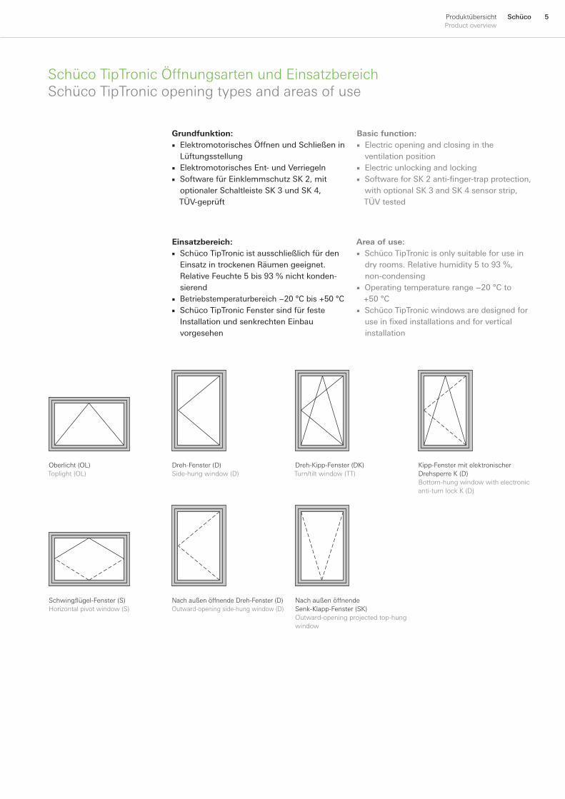
SchücoTipTronicÖffnungsartenundEinsatzbereichSchücoTipTronicopeningtypesandareasofuse
Dreh-Kipp-Fenster(DK)Turn/tiltwindow(TT)
Kipp-FenstermitelektronischerDrehsperreK(D)Bottom-hungwindowwithelectronicanti-turnlockK(D)
Dreh-Fenster(D)Side-hungwindow(D)
Oberlicht(OL)Toplight(OL)
NachaußenöffnendeDreh-Fenster(D)Outward-openingside-hungwindow(D)
NachaußenöffnendeSenk-Klapp-Fenster(SK)Outward-openingprojectedtop-hungwindow
Schwingflügel-Fenster (S)Horizontalpivotwindow(S)
Grundfunktion:Elektromotorisches Öffnen und Schließen in LüftungsstellungElektromotorisches Ent- und VerriegelnSoftware für Einklemmschutz SK 2, mit optionaler Schaltleiste SK 3 und SK 4, TÜV-geprüft
■
■■
Basic function:Electric opening and closing in the ventilation positionElectric unlocking and lockingSoftware for SK 2 anti-finger-trap protection, with optional SK 3 and SK 4 sensor strip, TÜV tested
■
■■
Einsatzbereich:Schüco TipTronic ist ausschließlich für den Einsatz in trockenen Räumen geeignet. Relative Feuchte 5 bis 93 % nicht konden-sierendBetriebstemperaturbereich −20 °C bis +50 °CSchüco TipTronic Fenster sind für feste Installation und senkrechten Einbau vorgesehen
■
■■
Area of use:Schüco TipTronic is only suitable for use in dry rooms. Relative humidity 5 to 93 %, non-condensingOperating temperature range −20 °C to +50 °CSchüco TipTronic windows are designed for use in fixed installations and for vertical installation
■
■
■
� Schüco ProduktübersichtProductoverview
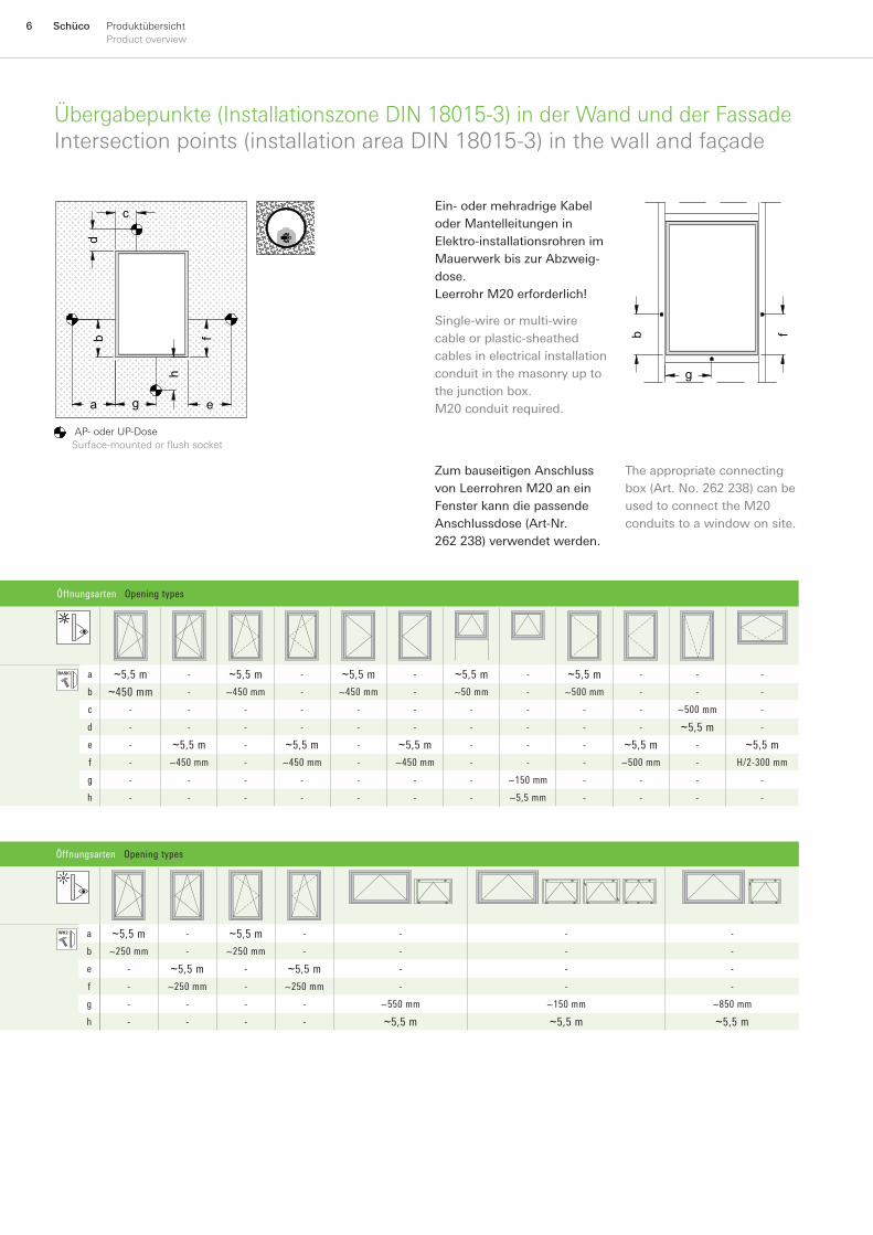
Übergabepunkte(InstallationszoneDIN18015-3)inderWandundderFassadeIntersectionpoints(installationareaDIN18015-3)inthewallandfaçade
Öffnungsarten Opening types
a ~5,5 m - ~5,5 m - ~5,5 m - ~5,5 m - ~5,5 m - - -
b ~450 mm - ~450 mm - ~450 mm - ~50 mm - ~500 mm - - -
c - - - - - - - - - - ~500 mm -
d - - - - - - - - - - ~5,5 m -
e - ~5,5 m - ~5,5 m - ~5,5 m - - - ~5,5 m - ~5,5 m
f - ~450 mm - ~450 mm - ~450 mm - - - ~500 mm - H/2-300 mm
g - - - - - - - ~150 mm - - - -
h - - - - - - - ~5,5 mm - - - -
Öffnungsarten Opening types
a ~5,5 m - ~5,5 m - - - -
b ~250 mm - ~250 mm - - - -
e - ~5,5 m - ~5,5 m - - -
f - ~250 mm - ~250 mm - - -
g - - - - ~550 mm ~150 mm ~850 mm
h - - - - ~5,5 m ~5,5 m ~5,5 m
d
a g
h
b
e
f b
g
f
c
AP-oderUP-DoseSurface-mounted or flush socket
Zum bauseitigen Anschluss von Leerrohren M20 an ein Fenster kann die passende Anschlussdose (Art-Nr. 262 238) verwendet werden.
Ein- oder mehradrige Kabel oder Mantelleitungen in Elektro-installationsrohren im Mauerwerk bis zur Abzweig-dose.Leerrohr M20 erforderlich!
d
a g
h
b
e
f b
g
f
c
Single-wire or multi-wire cable or plastic-sheathed cables in electrical installation conduit in the masonry up to the junction box.M20 conduit required.
The appropriate connecting box (Art. No. 262 238) can be used to connect the M20 conduits to a window on site.

�SchücoProduktübersichtProductoverview
AnschlussbeispieleConnectionexamples
BauseitigeAbzweigdoseJunctionboxonsite
A
AW2
AW2
TE1
optionalOptional
C
AW3
AW4
TE1
optionalOptional
E
AW2
AW2
TE1
AW2 AW2 AW2 AW2
IO
10x
1-10
IO
10x
11-20
IO
10x
21-30
GC
Biszu30FensterUpto30windows
B
AW2
AW2
TE1
AW2
D
AW4
AW4
TE1
AW4
� Schüco ProduktübersichtProductoverview
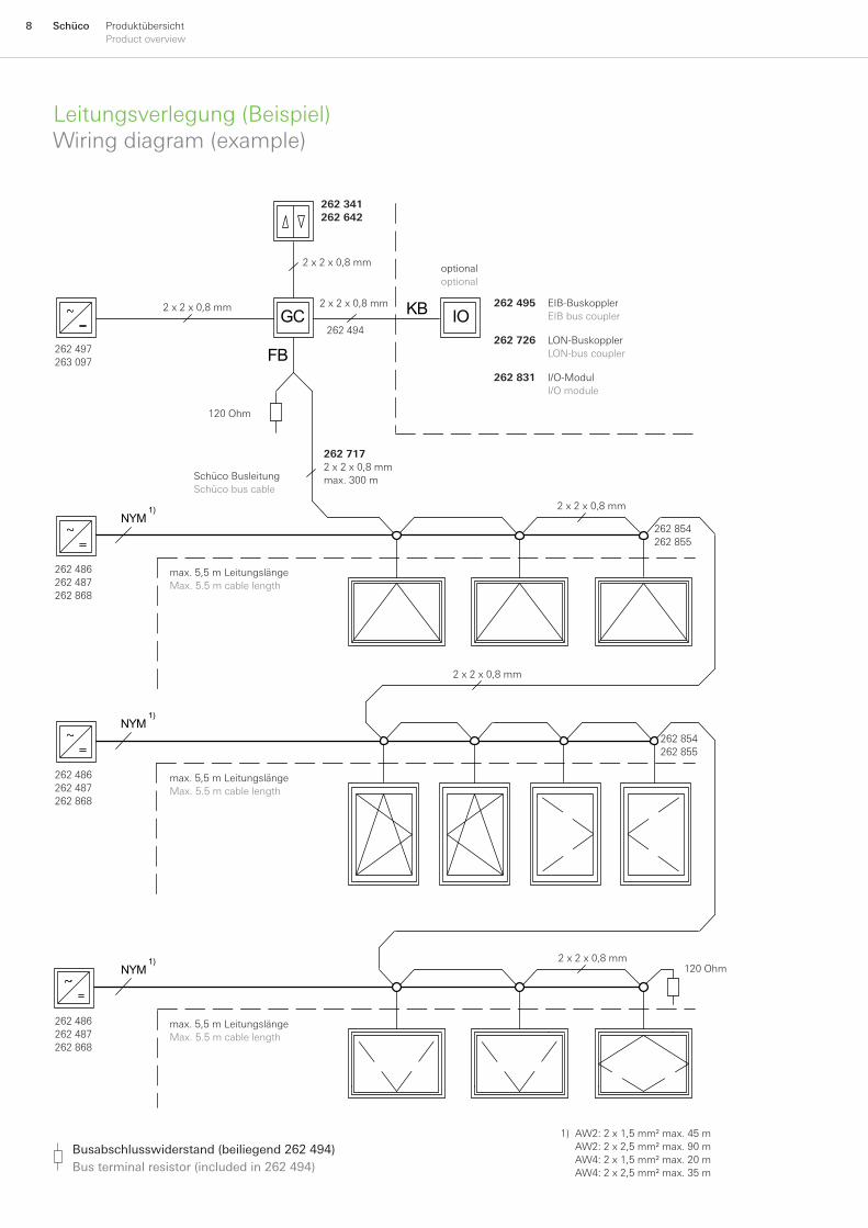
Leitungsverlegung(Beispiel)Wiringdiagram(example)
1) AW2: 2 x 1,5 mm² max. 45 m AW2: 2 x 2,5 mm² max. 90 m AW4: 2 x 1,5 mm² max. 20 m AW4: 2 x 2,5 mm² max. 35 m
Busabschlusswiderstand (beiliegend 262 494)Bus terminal resistor (included in 262 494)
NYM 1)
NYM 1)
NYM 1)
GC IOKB
FB
262 341262 642
optionaloptional
262 495 EIB-BuskopplerEIBbuscoupler
262 726 LON-BuskopplerLON-buscoupler
262 831 I/O-ModulI/Omodule
262 497263 097
SchücoBusleitungSchücobuscable
120Ohm
2x2x0,8mm
2x2x0,8mm
2x2x0,8mm
2x2x0,8mm
2x2x0,8mm
2x2x0,8mm
262 7172x2x0,8mmmax. 300 m
max. 5,5 m LeitungslängeMax. 5.5 m cable length
max. 5,5 m LeitungslängeMax. 5.5 m cable length
max. 5,5 m LeitungslängeMax. 5.5 m cable length
120Ohm
262 486262 487262868
262 854262855
262 486262 487262868
262 486262 487262868
262 854262855
262 494
Schüco Fensterautomation Schüco window automation
KNX/EIB
1
2
3
30
FB FB
1
2
3
30
Gebäudebus Building bus
Ethernet Buskoppler Ethernet bus connector
Schüco ControlPanel Schüco ControlPanel
Sensoren Sensors
Nachtauskühlung Night-time cooling
DK Turn/tilt
DK Turn/tilt
DK Turn/tilt
Kipp Bottom-hung
DK Turn/tilt
DK Turn/tilt
DK Turn/tilt
Kipp Bottom-hung
Schüco TipTronic KNX/EIB Buskoppler Schüco TipTronic KNX/EIB Bus coupler
Schüco TipTronic Gruppensteuergerät Schüco TipTronic Group control unit
Schüco TipTronic Gruppensteuergerät Schüco TipTronic Group control unit
Schüco TipTronic KNX/EIB Buskoppler Schüco TipTronic KNX/EIB Bus coupler
Wind Wind
Luftqualität Air quality
Regen Rain
Präsenz Occupancy
Licht Light
Raum-temperatur Room temperature
Außen-temperatur Outside temperature
Zeit Time
�SchücoProduktübersichtProductoverview
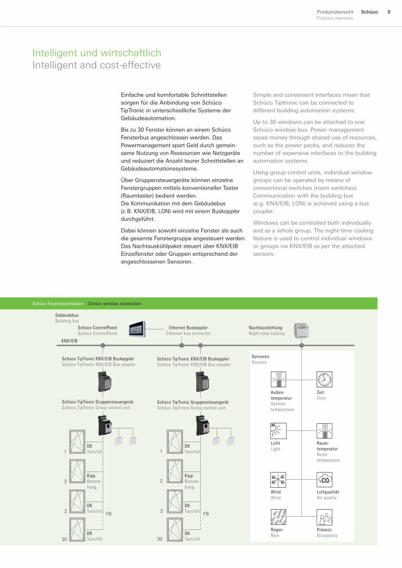
IntelligentundwirtschaftlichIntelligentandcost-effective
Simple and convenient interfaces mean that Schüco Tiptronic can be connected to different building automation systems.
Up to 30 windows can be attached to one Schüco window bus. Power management saves money through shared use of resources, such as the power packs, and reduces the number of expensive interfaces to the building automation systems.
Using group control units, individual window groups can be operated by means of conventional switches (room switches). Communication with the building bus (e.g. KNX/EIB, LON) is achieved using a bus coupler.
Windows can be controlled both individually and as a whole group. The night-time cooling feature is used to control individual windows or groups via KNX/EIB as per the attached sensors.
Einfache und komfortable Schnittstellen sorgen für die Anbindung von Schüco TipTronic in unterschiedliche Systeme der Gebäudeautomation.
Bis zu 30 Fenster können an einem Schüco Fensterbus angeschlossen werden. Das Powermanagement spart Geld durch gemein-same Nutzung von Ressourcen wie Netzgeräte und reduziert die Anzahl teurer Schnittstellen an Gebäudeautomationssysteme.
Über Gruppensteuergeräte können einzelne Fenstergruppen mittels konventioneller Taster (Raumtaster) bedient werden. Die Kommunikation mit dem Gebäudebus (z. B. KNX/EIB, LON) wird mit einem Buskoppler durchgeführt.
Dabei können sowohl einzelne Fenster als auch die gesamte Fenstergruppe angesteuert werden. Das Nachtauskühlpaket steuert über KNX/EIB Einzelfenster oder Gruppen entsprechend der angeschlossenen Sensoren.
Schüco Fensterautomation Schüco window automation
KNX/EIB
1
2
3
30
FB FB
1
2
3
30
Gebäudebus Building bus
Ethernet Buskoppler Ethernet bus connector
Schüco ControlPanel Schüco ControlPanel
Sensoren Sensors
Nachtauskühlung Night-time cooling
DK Turn/tilt
DK Turn/tilt
DK Turn/tilt
Kipp Bottom-hung
DK Turn/tilt
DK Turn/tilt
DK Turn/tilt
Kipp Bottom-hung
Schüco TipTronic KNX/EIB Buskoppler Schüco TipTronic KNX/EIB Bus coupler
Schüco TipTronic Gruppensteuergerät Schüco TipTronic Group control unit
Schüco TipTronic Gruppensteuergerät Schüco TipTronic Group control unit
Schüco TipTronic KNX/EIB Buskoppler Schüco TipTronic KNX/EIB Bus coupler
Wind Wind
Luftqualität Air quality
Regen Rain
Präsenz Occupancy
Licht Light
Raum-temperatur Room temperature
Außen-temperatur Outside temperature
Zeit Time
10 Schüco ProduktübersichtProductoverview
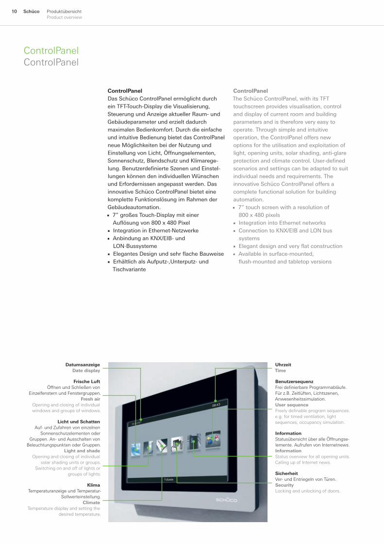
ControlPanelControlPanel
ControlPanelDas Schüco ControlPanel ermöglicht durch ein TFT-Touch-Display die Visualisierung, Steuerung und Anzeige aktueller Raum- und Gebäudeparameter und erzielt dadurch maximalen Bedienkomfort. Durch die einfache und intuitive Bedienung bietet das ControlPanel neue Möglichkeiten bei der Nutzung und Einstellung von Licht, Öffnungselementen, Sonnenschutz, Blendschutz und Klimarege-lung. Benutzerdefinierte Szenen und Einstel-lungen können den individuellen Wünschen und Erfordernissen angepasst werden. Das innovative Schüco ControlPanel bietet eine komplette Funktionslösung im Rahmen der Gebäudeautomation.
7” großes Touch-Display mit einer Auflösung von 800 x 480 PixelIntegration in Ethernet-NetzwerkeAnbindung an KNX/EIB- und LON-BussystemeElegantes Design und sehr flache BauweiseErhältlich als Aufputz-,Unterputz- und Tischvariante
■
■■
■■
ControlPanelThe Schüco ControlPanel, with its TFT touchscreen provides visualisation, control and display of current room and building parameters and is therefore very easy to operate. Through simple and intuitive operation, the ControlPanel offers new options for the utilisation and exploitation of light, opening units, solar shading, anti-glare protection and climate control. User-defined scenarios and settings can be adapted to suit individual needs and requirements. The innovative Schüco ControlPanel offers a complete functional solution for building automation.
7” touch screen with a resolution of 800 x 480 pixelsIntegration into Ethernet networksConnection to KNX/EIB and LON bus systemsElegant design and very flat constructionAvailable in surface-mounted, flush-mounted and tabletop versions
■
■■
■■
Datumsanzeige Date display
Frische LuftÖffnenundSchließenvon
Einzelfenstern und Fenstergruppen.Fresh air
Openingandclosingofindividualwindows and groups of windows.
Licht und SchattenAuf-undZufahrenvoneinzelnen
SonnenschutzelementenoderGruppen. An- und Ausschalten von
Beleuchtungspunkten oder Gruppen.Light and shade
Openingandclosingofindividualsolar shading units or groups.
Switchingonandoffoflightsorgroups of lights.
KlimaTemperaturanzeigeundTemperatur-
Sollwerteinstellung.Climate
Temperaturedisplayandsettingthedesired temperature.
SicherheitVer- und Entriegeln von Türen.SecurityLocking and unlocking of doors.
BenutzersequenzFrei definierbare Programmabläufe. Für z.B. Zeitlüften, Lichtszenen, Anwesenheitssimulation.User sequenceFreely definable program sequences. e.g. for timed ventilation, light sequences, occupancy simulation.
InformationStatusübersichtüberalleÖffnungse-lemente. Aufrufen von Internetnews.InformationStatus overview for all opening units. Calling up of Internet news.
UhrzeitTime

11SchücoProduktübersichtProductoverview
ControlPanelSoftwareControlPanelSoftware
ControlPanel SoftwareDie Schüco ControlPanel Software dient zur Erstellung und Parametrierung von individu-ellen Gebäude-Visualisierungen für ein oder mehreren Schüco ControlPanels. Datenpunkte aus der ETS 2/3, einem OPC XML/DA-Server oder einem Schüco TipTronic Gruppensteuer-gerät können importiert und zugeordnet werden. Anschließend werden diese Daten-punkte per Drag & Drop mit den Schalt- und Anzeigeelementen der Visualisierung ver-knüpft. Zusätzliche Programme wie z.B. der Internet-Explorer können direkt aus der Visualisierung heraus gestartet werden. Das Visualisierungsprojekt kann bereits vom PC aus in voller Funktion getestet und anschlie-ßend über eine CF-Karte oder über ein Netzwerk in das Schüco ControlPanel geladen werden.
ControlPanel software The purpose of the Schüco ControlPanel software is to create the parameters for individual building monitoring for one or more Schüco ControlPanels. Data can be imported and included from the ETS 2 / 3, an OPC XML/DA server or a Schüco Tiptronic group control unit. Subsequently, this data will be linked using Drag & Drop to the switch and display elements of the visualisation program. Additional programs such as Internet Explorer can be started directly from the visualisation program. The full functionality of the visualisa-tion project can be tested from a PC and then loaded into the Schüco ControlPanel using a CF card or via a network.
12 Schüco ProduktübersichtProductoverview
Schüco Fensterautomation Schüco window automation
SchücoFunksystemSchücoradio-controlledsystem
Profilintegrierte Funkempfänger für Schüco TipTronicProfile-integrated radio receiver for Schüco TipTronic
Funkempfänger extern für Sonnenschutz, usw.External radio receiver for solar shading etc.
FunksenderRadiotransmitter
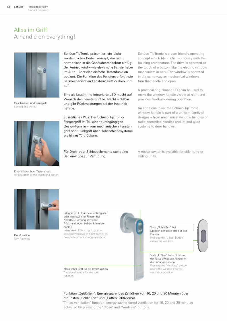
AllesimGriffAhandleoneverything!
Funktion „Zeitlüften“: Energiesparendes Zeitlüften von 10, 20 und 30 Minuten über die Tasten „Schließen“ und „Lüften“ aktivierbar.
"Timed ventilation" function: energy-saving timed ventilation for 10, 20 and 30 minutes activated by pressing the "Close" and "Ventilate" buttons.
IntegrierteLEDfürBeleuchtungalleroderausgewählterFensterbeiNachtbeleuchtungsowiefürRückmeldungenbeiderInbetrieb-nahmeIntegratedLEDstolightupallorselectedwindowsatnightaswellasprovide feedback during operation.
Taste„Lüften“beimDrückenderTasteöffnetdasFensterindieLüftungsstellungPressingthe"Ventilate"buttonopensthewindowintotheventilationposition
Taste„Schließen“beimDrückenderTasteschließtdasFensterPressingthe"Close"buttonclosesthewindow
KlassischerGrifffürdieDrehfunktionTraditionalhandlefortheturnfunction
Schüco TipTronic präsentiert ein leicht verständliches Bedienkonzept, das sich harmonisch in die Gebäudearchitektur einfügt. Der Antrieb wird – wie elektrische Fensterheber im Auto – über eine einfache Tastenfunktionbedient. Die Funktion des Fensters erfolgt wie bei mechanischen Fenstern: Griff drehen und auf!
Eine als Leuchtring integrierte LED macht auf Wunsch den Fenstergriff bei Nacht sichtbar und gibt Rückmeldungen bei der Inbetrieb-nahme.
Zusätzliches Plus: Der Schüco TipTronic-Fenstergriff ist Teil einer durchgängigen Design-Familie – vom mechanischen Fenster-griff oder Funkgriff über Hebeschiebesysteme bis hin zu Türdrückern.
Für Dreh- oder Schiebeelemente steht eine Bedienwippe zur Verfügung.
DrehfunktionTurnfunction
GeschlossenundverriegeltLockedandbolted
KippfunktionüberTastendruckTiltoperationatthetouchofabutton
A rocker switch is available for side-hung or sliding units.
Schüco TipTronic is a user-friendly operating concept which blends harmoniously with the building architecture. The drive is operated at the touch of a button, like the electric window mechanism in cars. The window is operated in the same way as mechanical windows: turn the handle and open.
A practical ring-shaped LED can be used to make the window handle visible at night and provides feedback during operation.
An additional plus: the Schüco TipTronic window handle is part of a uniform family of designs – from mechanical window handles or radio-controlled handles and lift-and-slide systems to door handles.
13SchücoProduktübersichtProductoverview
Schüco Fensterautomation Schüco window automation
SchücoFunksystemSchücoradio-controlledsystem
Profi lintegrierte Funkempfänger für Schüco TipTronicProfi le-integrated radio receiver for Schüco TipTronic
Funkempfänger extern für Sonnenschutz, usw.External radio receiver for solar shading etc.
FunksenderRadiotransmitter
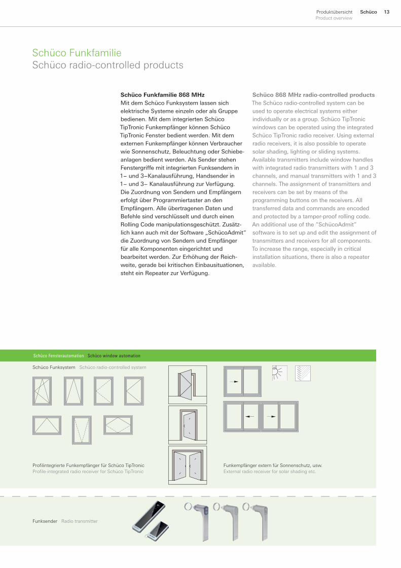
SchücoFunkfamilieSchücoradio-controlledproducts
Schüco Funkfamilie 868 MHzMit dem Schüco Funksystem lassen sich elektrische Systeme einzeln oder als Gruppe bedienen. Mit dem integrierten Schüco TipTronic Funkempfänger können Schüco TipTronic Fenster bedient werden. Mit dem externen Funkempfänger können Verbraucher wie Sonnenschutz, Beleuchtung oder Schiebe-anlagen bedient werden. Als Sender stehen Fenstergriffe mit integrierten Funksendern in 1− und 3−Kanalausführung, Handsender in 1− und 3− Kanalausführung zur Verfügung. Die Zuordnung von Sendern und Empfängern erfolgt über Programmiertaster an den Empfängern. Alle übertragenen Daten und Befehle sind verschlüsselt und durch einen Rolling Code manipulationsgeschützt. Zusätz-lich kann auch mit der Software „SchücoAdmit“die Zuordnung von Sendern und Empfänger für alle Komponenten eingerichtet und bearbeitet werden. Zur Erhöhung der Reich-weite, gerade bei kritischen Einbausituationen, steht ein Repeater zur Verfügung.
Schüco 868 MHz radio-controlled productsThe Schüco radio-controlled system can be used to operate electrical systems either individually or as a group. Schüco TipTronic windows can be operated using the integrated Schüco TipTronic radio receiver. Using external radio receivers, it is also possible to operate solar shading, lighting or sliding systems. Available transmitters include window handles with integrated radio transmitters with 1 and 3 channels, and manual transmitters with 1 and 3 channels. The assignment of transmitters and receivers can be set by means of the programming buttons on the receivers. All transferred data and commands are encoded and protected by a tamper-proof rolling code. An additional use of the “SchücoAdmit” software is to set up and edit the assignment of transmitters and receivers for all components. To increase the range, especially in critical installation situations, there is also a repeater available.
1� Schüco ProduktübersichtProductoverview
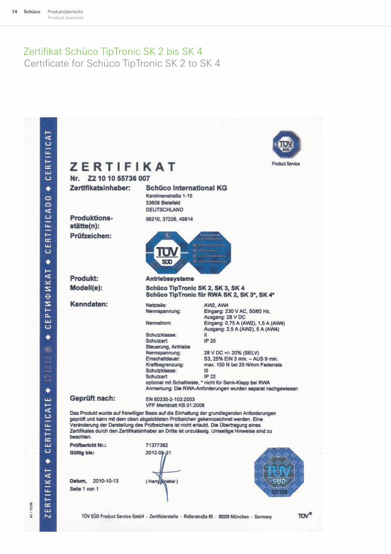
Zertifikat Schüco TipTronic SK 2 bis SK 4Certificate for Schüco TipTronic SK 2 to SK 4

1�SchücoProduktübersichtProductoverview
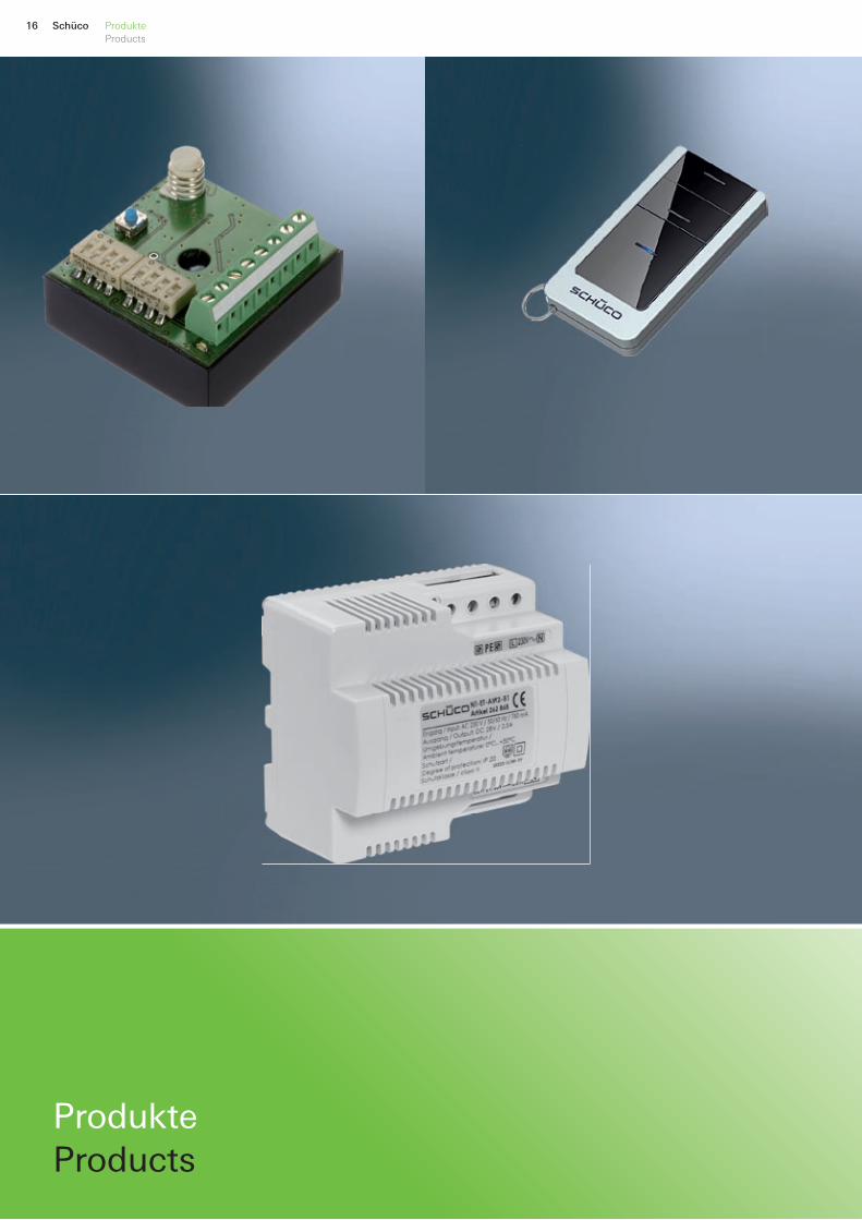
16 Schüco ProdukteProducts
Produkte Products
17SchücoProdukteProducts
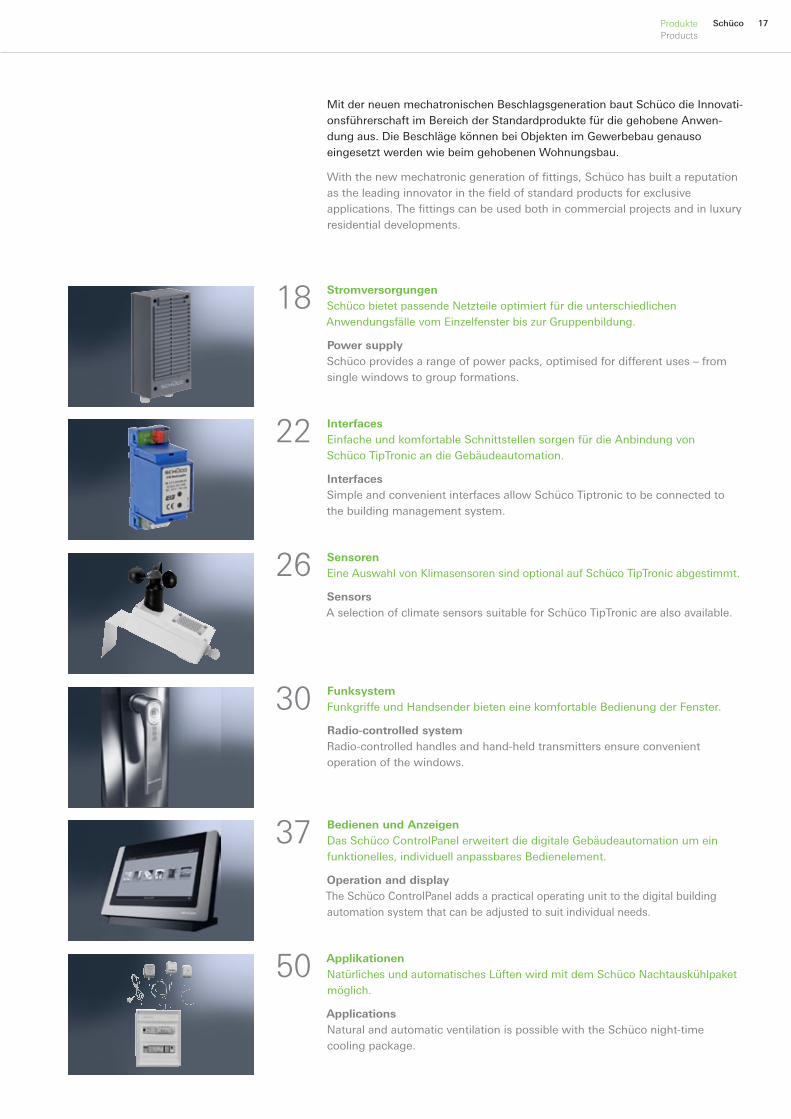
Mit der neuen mechatronischen Beschlagsgeneration baut Schüco die Innovati-onsführerschaft im Bereich der Standardprodukte für die gehobene Anwen-dung aus. Die Beschläge können bei Objekten im Gewerbebau genauso eingesetzt werden wie beim gehobenen Wohnungsbau.
With the new mechatronic generation of fittings, Schüco has built a reputation as the leading innovator in the field of standard products for exclusive applications. The fittings can be used both in commercial projects and in luxury residential developments.
FunksystemFunkgriffe und Handsender bieten eine komfortable Bedienung der Fenster.
Radio-controlled systemRadio-controlled handles and hand-held transmitters ensure convenient operation of the windows.
Bedienen und AnzeigenDas Schüco ControlPanel erweitert die digitale Gebäudeautomation um ein funktionelles, individuell anpassbares Bedienelement.
Operation and displayThe Schüco ControlPanel adds a practical operating unit to the digital building automation system that can be adjusted to suit individual needs.
ApplikationenNatürliches und automatisches Lüften wird mit dem Schüco Nachtauskühlpaket möglich.
ApplicationsNatural and automatic ventilation is possible with the Schüco night-time cooling package.
SensorenEine Auswahl von Klimasensoren sind optional auf Schüco TipTronic abgestimmt.
SensorsA selection of climate sensors suitable for Schüco TipTronic are also available.
StromversorgungenSchüco bietet passende Netzteile optimiert für die unterschiedlichen Anwendungsfälle vom Einzelfenster bis zur Gruppenbildung.
Power supplySchüco provides a range of power packs, optimised for different uses – from single windows to group formations.
InterfacesEinfache und komfortable Schnittstellen sorgen für die Anbindung von Schüco TipTronic an die Gebäudeautomation.
InterfacesSimple and convenient interfaces allow Schüco Tiptronic to be connected to the building management system.
22
18
26
50
37
30
18 Schüco Produkte • StromversorgungenProducts • Power supplies
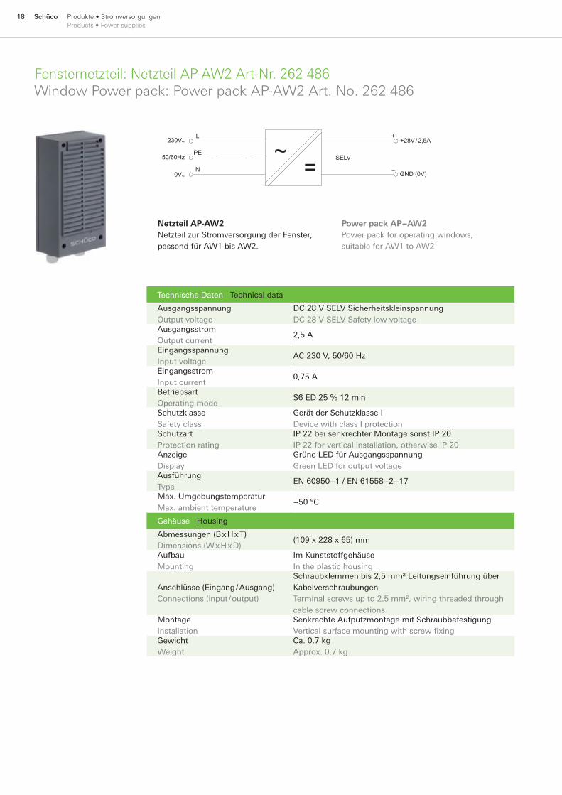
Fensternetzteil: Netzteil AP-AW2 Art-Nr. 262 486 Window Power pack: Power pack AP-AW2 Art. No. 262 486
Technische Daten Technical data
Ausgangsspannung Output voltage
DC 28 V SELV Sicherheitskleinspannung DC 28 V SELV Safety low voltage
Ausgangsstrom Output current
2,5 A
Eingangsspannung Input voltage
AC 230 V, 50/60 Hz
Eingangsstrom Input current
0,75 A
Betriebsart Operating mode
S6 ED 25 % 12 min
Schutzklasse Safety class
Gerät der Schutzklasse I Device with class I protection
Schutzart Protection rating
IP 22 bei senkrechter Montage sonst IP 20 IP 22 for vertical installation, otherwise IP 20
Anzeige Display
Grüne LED für Ausgangsspannung Green LED for output voltage
Ausführung Type
EN 60950−1 / EN 61558−2−17
Max. Umgebungstemperatur Max. ambient temperature
+50 °C
Gehäuse Housing
Abmessungen (B x H x T) Dimensions (W x H x D)
(109 x 228 x 65) mm
Aufbau Mounting
Im Kunststoffgehäuse In the plastic housing
Anschlüsse (Eingang / Ausgang) Connections (input / output)
Schraubklemmen bis 2,5 mm² Leitungseinführung über Kabelverschraubungen Terminal screws up to 2.5 mm², wiring threaded through cable screw connections
Montage Installation
Senkrechte Aufputzmontage mit Schraubbefestigung Vertical surface mounting with screw fixing
Gewicht Weight
Ca. 0,7 kg Approx. 0.7 kg
~=
230V~
0V~
50/60Hz
+28V/ 2,5A
GND (0V)
SELV
L
PE
N
+
−
Netzteil AP-AW2Netzteil zur Stromversorgung der Fenster, passend für AW1 bis AW2.
Power pack AP−AW2Power pack for operating windows, suitable for AW1 to AW2

19SchücoProdukte • StromversorgungenProducts • Power supplies
Fensternetzteil: Netzteil AP-AW4 Art-Nr. 262 487 Window Power pack: Power pack AP-AW4 Art. No. 262 487
Technische Daten Technical data
Ausgangsspannung Output voltage
DC 28 V SELV Sicherheitskleinspannung DC 28 V SELV Safety low voltage
Ausgangsstrom Output current
5,0 A
Eingangsspannung Input voltage
AC 230 V 50/60 Hz
Eingangsstrom Input current
1,5 A
Betriebsart Operating mode
S6 ED 25 % 12 min
Schutzklasse Safety class
Gerät der Schutzklasse I Device with class I protection
Schutzart Protection rating
IP 22 bei senkrechter Montage sonst IP 20 IP 22 for vertical installation, otherwise IP 20
Anzeige Display
Grüne LED für Ausgangsspannung Green LED for output voltage
Ausführung Type
EN 60950−1 / EN 61558−2−17
max. Umgebungstemperatur Max. ambient temperature
+50 °C
Gehäuse Housing
Abmessungen (B x H x T) Dimensions (W x H x D)
(109 x 228 x 65) mm
Aufbau Mounting
im Kunststoffgehäuse In the plastic housing
Anschlüsse (Eingang / Ausgang) Connections (input / output)
Schraubklemmen bis 2,5 mm² Leitungseinführung über Kabelverschraubungen Terminal screws up to 2.5 mm², wiring threaded through cable screw connections
Montage Installation
Senkrechte Aufputzmontage mit Schraubbefestigung Vertical surface mounting with screw fixing
Gewicht Weight
Ca. 0,8 kg Approx. 0.8 kg
Netzteil AP-AW4Netzteil zur Stromversorgung der Fenster, passend für AW1 bis AW4.
~=
230V~
0V~
50/60Hz
+28V/ 5,0A
GND (0V)
SELV
L
PE
N
+
−
Power pack AP-AW4Power pack for operating windows, suitable for AW1 to AW4.

20 Schüco Produkte • StromversorgungenProducts • Power supplies
Fensternetzteil: Netzteil ET-AW2 Art-Nr. 262 868 Window Power pack: Power pack ET-AW2 Art. No. 262 868
Technische Daten Technical data
Ausgangsspannung Output voltage
DC 28 V SELV Sicherheitskleinspannung DC 28 V SELV safety extra-low voltage
Ausgangsstrom Output current
2,5 A
Eingangsspannung Input voltage
AC 230 V 50/60 Hz
Eingangsstrom Input current
0,8 A
Betriebsart Operating mode
S6 ED 25 % 12 min.
Schutzklasse Safety class
Gerät der Schutzklasse II Device in safety class II
Schutzart Protection rating
IP 20 (eingebaut in Elektroverteiler) IP 20 (installed in the distributor)
max. Umgebungstemperatur Max. ambient temperature
+50 °C
Gehäuse Housing
Abmessungen (B x H x T) Dimensions (WxHxD)
6 TE (105 x 93 x 67) mm6 module (105 x 93 x 67) mm
Anschlüsse (Eingang / Ausgang) Connections (input / output)
Schraubklemmen 1,5 mm²Terminal screws 1.5 mm²
Montage Installation
Hutschienenmontage auf Normprofilschiene Top hat mounting on standardised profile rail
~=
230V~
0V~
50/60Hz
+28V/ 2,5A
GND (0V)
SELV
L
PE
N
+
−
Netzteil ET-AW2Netzteil zur Stromversorgung der Fenster, passend für AW1 bis AW2. Zur Leistungser-höhung können maximal 2 Netzteile parallel geschaltet werden, passend für AW1 bis AW4.
Power pack ET-AW2Power pack for supplying power to the window, suitable for AW1 to AW2. To increase output, up to 2 powerpacks can be operated in parallel, suitable for AW1 to AW4.
21SchücoProdukte • StromversorgungenProducts • Power supplies
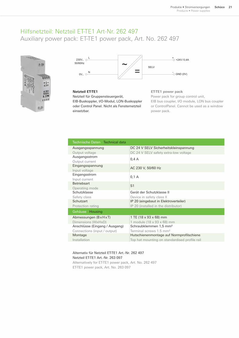
Hilfsnetzteil: Netzteil ET-TE1 Art-Nr. 262 497 Auxiliary power pack: ET-TE1 power pack, Art. No. 262 497
Technische Daten Technical data
Ausgangsspannung Output voltage
DC 24 V SELV Sicherheitskleinspannung DC 24 V SELV safety extra-low voltage
Ausgangsstrom Output current
0,4 A
Eingangsspannung Input voltage
AC 230 V, 50/60 Hz
Eingangsstrom Input current
0,1 A
Betriebsart Operating mode
S1
Schutzklasse Safety class
Gerät der Schutzklasse II Device in safety class II
Schutzart Protection rating
IP 20 (eingebaut in Elektroverteiler) IP 20 (installed in the distributor)
Gehäuse Housing
Abmessungen (B x H x T) Dimensions (WxHxD)
1 TE (18 x 93 x 68) mm1 module (18 x 93 x 68) mm
Anschlüsse (Eingang / Ausgang) Connections (input / output)
Schraubklemmen 1,5 mm²Terminal screws 1.5 mm²
Montage Installation
Hutschienenmontage auf Normprofilschiene Top hat mounting on standardised profile rail
~=
230V~
0V~
50/60Hz+24V/ 0,4A
GND (0V)
SELV
L
N
+
−
Netzteil ET-TE1Netzteil für Gruppensteuergerät, EIB-Buskoppler, I/O-Modul, LON-Buskoppler oder Control Panel. Nicht als Fensternetzteil einsetzbar.
ET-TE1 power packPower pack for group control unit, EIB bus coupler, I/O module, LON bus coupler or ControlPanel. Cannot be used as a window power pack.
Alternativ für Netzteil ET-TE1 Art.-Nr. 262 497 Netzteil ET-TE1 Art.-Nr. 263 097 Alternatively for ET-TE1 power pack, Art. No. 262 497 ET-TE1 power pack, Art. No. 263 097

22 Schüco Produkte • InterfacesProducts • Interfaces
Gruppensteuergerät GS-ET2 Art-Nr. 262 494Group control unit GS-ET2 Art. No. 262 494
Technische Daten Technical data
Spannungsversorgung Power supply
DC 24 V
Stromaufnahme Current consumption
Max. 100 mA
Busanschluss (1) Bus connection (1)
Schüco Fensterbus (FB) Schüco window Bus (FB)
Busanschluss (2) Bus connection (2)
Kommunikationsbus (KB) Communications BUS (KB)
Inbetriebnahme Commissioning
Anschluss an Busadapter-Interface über Service-Port Connection to bus adapter interface via service port
Konventionelle Steuerung Conventional control system
Eingänge zur Ansteuerung der gesamten Fenstergruppe Inputs to control the whole window group
Bedienelement Operating unit
Programmiertaster Programming button
Anzahl Fenster Number of windows
Max. 30
Schutzart Protection rating
IP 20 (eingebaut in Elektroverteiler) IP 20 (installed in the distributor)
Gehäuse Housing
Abmessungen (B x H x T) Dimensions (WxHxD)
2 TE (35 x 90 x 58) mm 2 module (35 x 90 x 58) mm
Montage Installation
Hutschienenmontage auf Normprofilschiene Top hat mounting on standardised profile rail
Gruppensteuergerät GS-ET2Basisgerät für Schüco TipTronic Fenster. Mittels Gruppensteuergerät können bis zu 30 Fenster über den Schüco Fensterbus (FB) zusammengeschlossen werden und gemein-sam durch konventionelle Taster und/oder Schalter bedient werden.
1 8
9 16
1
8
ProgrammiertasterProgramming button
LED
Service-PortService port
Kommunikationsbus (KB)Communications BUS (KB)
GS-ET2 group control unitBasic unit for Schüco TipTronic windows. Using a group control unit, up to 30 windows can be connected together using the Schüco window bus (FB) and can be operated using conventional buttons and / or switches.
23SchücoProdukte • InterfacesProducts • Interfaces
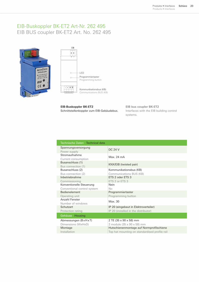
EIB-Buskoppler BK-ET2 Art-Nr. 262 495EIB BUS coupler BK-ET2 Art. No. 262 495
Technische Daten Technical data
Spannungsversorgung Power supply
DC 24 V
Stromaufnahme Current consumption
Max. 24 mA
Busanschluss (1) Bus connection (1)
KNX/EIB (twisted pair)
Busanschluss (2) Bus connection (2)
Kommunikationsbus (KB) Communications BUS (KB)
Inbetriebnahme Commissioning
ETS 2 oder ETS 3 ETS 2 or ETS 3
Konventionelle Steuerung Conventional control system
Nein No
Bedienelement Operating unit
Programmiertaster Programming button
Anzahl Fenster Number of windows
Max. 30
Schutzart Protection rating
IP 20 (eingebaut in Elektroverteiler) IP 20 (installed in the distributor)
Gehäuse Housing
Abmessungen (B x H x T) Dimensions (WxHxD)
2 TE (35 x 90 x 58) mm 2 module (35 x 90 x 58) mm
Montage Installation
Hutschienenmontage auf Normprofilschiene Top hat mounting on standardised profile rail
EIB-Buskoppler BK-ET2Schnittstellenkoppler zum EIB-Gebäudebus.
EIB
E E
BA+-
+ -
LED
Kommunikationsbus (KB)Communications BUS (KB)
ProgrammiertasterProgramming button
EIB bus coupler BK-ET2Interfaces with the EIB building control systems.
24 Schüco Produkte • InterfacesProducts • Interfaces
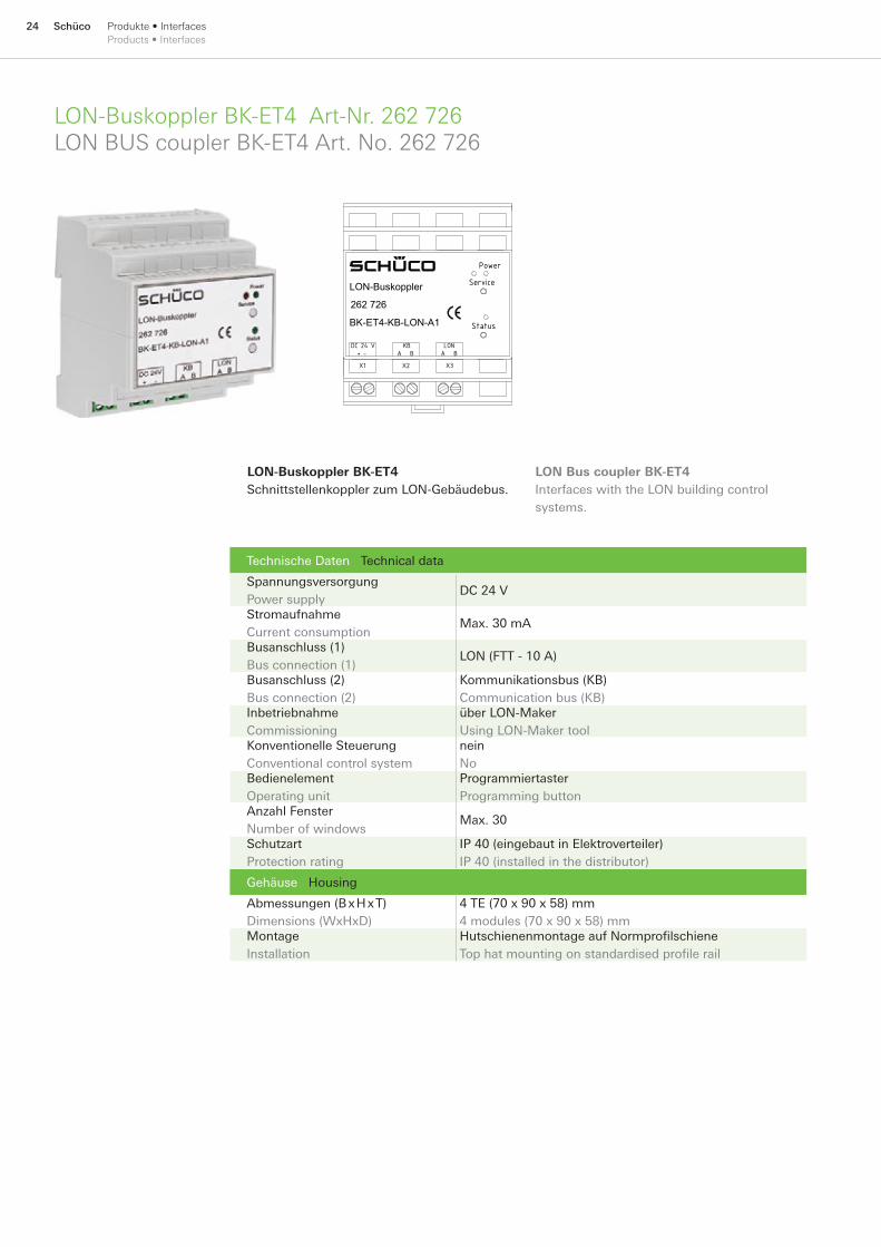
LON-Buskoppler BK-ET4 Art-Nr. 262 726LON BUS coupler BK-ET4 Art. No. 262 726
Technische Daten Technical data
Spannungsversorgung Power supply
DC 24 V
Stromaufnahme Current consumption
Max. 30 mA
Busanschluss (1) Bus connection (1)
LON (FTT - 10 A)
Busanschluss (2) Bus connection (2)
Kommunikationsbus (KB) Communication bus (KB)
Inbetriebnahme Commissioning
über LON-Maker Using LON-Maker tool
Konventionelle Steuerung Conventional control system
nein No
Bedienelement Operating unit
Programmiertaster Programming button
Anzahl Fenster Number of windows
Max. 30
Schutzart Protection rating
IP 40 (eingebaut in Elektroverteiler) IP 40 (installed in the distributor)
Gehäuse Housing
Abmessungen (B x H x T) Dimensions (WxHxD)
4 TE (70 x 90 x 58) mm 4 modules (70 x 90 x 58) mm
Montage Installation
Hutschienenmontage auf Normprofilschiene Top hat mounting on standardised profile rail
LON-Buskoppler BK-ET4Schnittstellenkoppler zum LON-Gebäudebus.
Power
Status
LON-Buskoppler
262 726
BK-ET4-KB-LON-A1
DC 24 V + -
KB A B
LON A B
Service
X1 X2 X3
LON Bus coupler BK-ET4Interfaces with the LON building control systems.

25SchücoProdukte • InterfacesProducts • Interfaces
I/O-Modul SM-ET4 Art-Nr. 262 831I/O-Modul SM-ET4 Art. No. 262 831
Technische Daten Technical data
Spannungsversorgung Power supply
DC 24 V
Stromaufnahme Current consumption
Max. 200 mA
Busanschluss Bus connection
Kommunikationsbus (KB) Communication bus (KB)
Konventionelle Steuerung Conventional control system
Eingänge zur Ansteuerung von 10 Fenstern Inputs to control of 10 windows
Anzahl der I/O-Module je Gruppen-steuergerät (GC) Number of I/O modules per group control unit (GC)
Max. 3
Anzahl Fenster Number of windows
Max. 10
Anzahl der Schaltrelais Number of switching relays
2 (max. 50 V / 1 A)
Schutzart Protection rating
IP 20 (eingebaut in Elektroverteiler) IP 20 (installed in the distributor)
Gehäuse Housing
Abmessungen (BxHxT) Dimensions (WxHxD)
4 TE (70 x 90 x 58) mm 4 modules (70 x 90 x 58) mm
I/O-Modul SM-ET4Zusatzgerät für eine Einzelsteuerung der Fenster über konventionelle Lüftungstaster.
Aufputzgehäuse KV-AP12 (262 498) separat bestellenOrder surface-mounted housing KV-AP12 (262 498) separately
1
8
Control
Service-Port
Status
1 2 3 4 5 6 7 8 9 10 11 12 13 14 15 16 17 18
19 20 21 22 23 24 25 26 27 28 29 30 31
TipTronic
I/O-Modul
262 831
32 33 34 35 36
DIP
SM-ET4 I/O moduleAdditional device for individual control of windows using conventional ventilation buttons.

26 Schüco Produkte•SensorenProducts•Sensors
Wind-undRegenmelderWRM24VArt-Nr.242164WindandrainsensorWRM24VArt.No.242164
Technische Daten Technical data
Spannungsversorgung Power supply
AC/DC 20-30 V
Stromaufnahme Current consumption
~ 100 mA
Temperaturbereich Temperature range
-20 °C bis +50 °C -20 °C to +50 °C
Relaisausgang Relay output
1 x Wechsler (30 V / 1 A) 1 x change-over contact (30 V / 1 A)
Schutzart Protection rating
IP 65 (für den Außenbereich) IP 65 (for use outside)
Gehäuse Housing
Abmessungen (BxHxT) Dimensions (WxHxD)
Ohne Windrad (82 x 160 x 55) mm Without wind wheel (82 x 160 x 55) mm
Montage Installation
Aufputzmontage mit Schraubbefestigung For surface mounting with screw fixing
Wind- und Regenmelder WRM 24VKombinierter Wind/Regenmelder für den Außenbereich zum automatischen Schließen von Schüco TipTronic Fenstergruppen, passend für Schüco TipTronic Gruppensteuer-gerät und Nachtauskühlpaket.Einstellbare Funktionen:
Schaltwert für Windgeschwindigkeit (3-20 m/s)Zeit für Einschaltverzögerung (10-30 s)Deaktivierung von Wind- oder Regenmelder
■
■
■
+24V
0V
NC
COM
WRM 24V
NOK1
Wind and rain sensor WRM 24VCombined wind/rain sensor for external use for automatic closing of Schüco TipTronic window groups, suitable for Schüco TipTronic group control unit and night-time cooling package.
Adjustable functions:Trigger value for wind speed (3-20 m/s)
Time for switch-on delay (10-30 s)
Deactivation of wind or rain sensor
■
■
■
Alternativ für Wind- und Regenmelder WRM 24V Art.-Nr. 242 164 Wind- und Regenmelder WRM/2 24V Art.-Nr. 267 732 Alternatively for Wind and rain sensor WRM 24 V Art. No. 242 164 Wind and rain sensor WRM/2 24 V Art. No. 267 732
27SchücoProdukte•SensorenProducts•Sensors
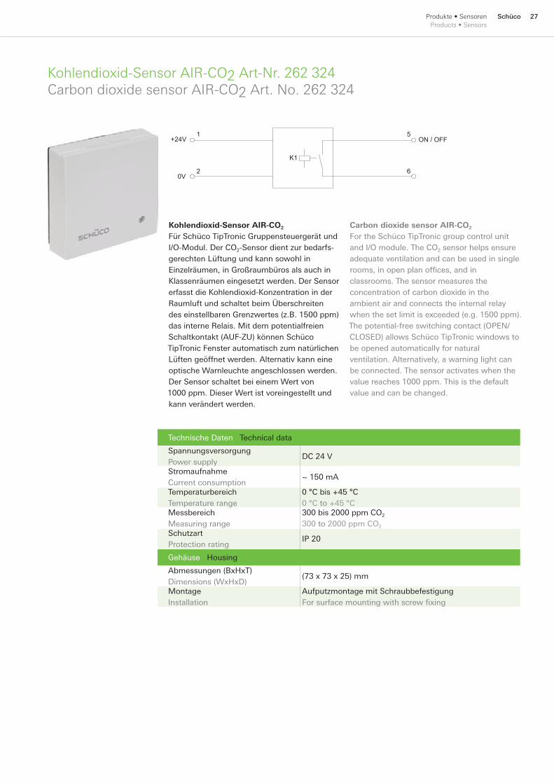
Kohlendioxid-SensorAIR-CO2Art-Nr.262324CarbondioxidesensorAIR-CO2Art.No.262324
Technische Daten Technical data
Spannungsversorgung Power supply
DC 24 V
Stromaufnahme Current consumption
~ 150 mA
Temperaturbereich Temperature range
0 °C bis +45 °C 0 °C to +45 °C
Messbereich Measuring range
300 bis 2000 ppm CO2 300 to 2000 ppm CO2
Schutzart Protection rating
IP 20
Gehäuse Housing
Abmessungen (BxHxT) Dimensions (WxHxD)
(73 x 73 x 25) mm
Montage Installation
Aufputzmontage mit Schraubbefestigung For surface mounting with screw fixing
Kohlendioxid-Sensor AIR-CO2
Für Schüco TipTronic Gruppensteuergerät und I/O-Modul. Der CO2-Sensor dient zur bedarfs-gerechten Lüftung und kann sowohl in Einzelräumen, in Großraumbüros als auch in Klassenräumen eingesetzt werden. Der Sensor erfasst die Kohlendioxid-Konzentration in der Raumluft und schaltet beim Überschreiten des einstellbaren Grenzwertes (z.B. 1500 ppm) das interne Relais. Mit dem potentialfreien Schaltkontakt (AUF-ZU) können Schüco TipTronic Fenster automatisch zum natürlichen Lüften geöffnet werden. Alternativ kann eine optische Warnleuchte angeschlossen werden. Der Sensor schaltet bei einem Wert von 1000 ppm. Dieser Wert ist voreingestellt und kann verändert werden.
+24V
0V
ON / OFF
K1
1
2
5
6
Carbon dioxide sensor AIR-CO2
For the Schüco TipTronic group control unit and I/O module. The CO2 sensor helps ensure adequate ventilation and can be used in single rooms, in open plan offices, and in classrooms. The sensor measures the concentration of carbon dioxide in the ambient air and connects the internal relay when the set limit is exceeded (e.g. 1500 ppm). The potential-free switching contact (OPEN/CLOSED) allows Schüco TipTronic windows to be opened automatically for natural ventilation. Alternatively, a warning light can be connected. The sensor activates when the value reaches 1000 ppm. This is the default value and can be changed.
28 Schüco Produkte•SensorenProducts•Sensors
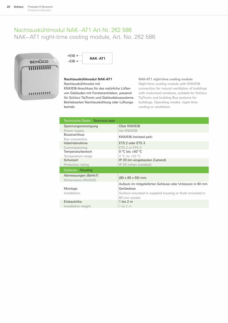
Nachtauskühlmodul NAK−AT1 Art-Nr. 262 586NAK−AT1 night-time cooling module, Art. No. 262 586
Technische Daten Technical data
Spannungsversorgung Power supply
Über KNX/EIB Via KNX/EIB
Busanschluss Bus connection
KNX/EIB (twisted pair)
Inbetriebnahme Commissioning
ETS 2 oder ETS 3 ETS 2 or ETS 3
Temperaturbereich Temperature range
0 °C bis +50 °C 0 °C to +50 °C
Schutzart Protection rating
IP 20 (im eingebauten Zustand) IP 20 (when installed)
Gehäuse Housing
Abmessungen (BxHxT) Dimensions (WxHxD)
(80 x 80 x 59) mm
Montage Installation
Aufputz im mitgelieferten Gehäuse oder Unterputz in 60 mm Gerätedose Surface-mounted in supplied housing or flush-mounted in 60 mm socket
Einbauhöhe Installation height
1 bis 2 m 1 to 2 m
+EIB−EIB
NAK−AT1
Nachtauskühlmodul NAK-AT1Nachtauskühlmodul mit KNX/EIB-Anschluss für das natürliche Lüften von Gebäuden mit Fensterantrieben, passend für Schüco TipTronic und Gebäudebussysteme. Betriebsarten Nachtauskühlung oder Lüftungs-betrieb.
NAK-AT1 night-time cooling moduleNight-time cooling module with KNX/EIB connection for natural ventilation of buildings with motorised windows, suitable for Schüco TipTronic and building Bus systems for buildings. Operating modes: night-time cooling or ventilation.
29SchücoProdukte•SensorenProducts•Sensors
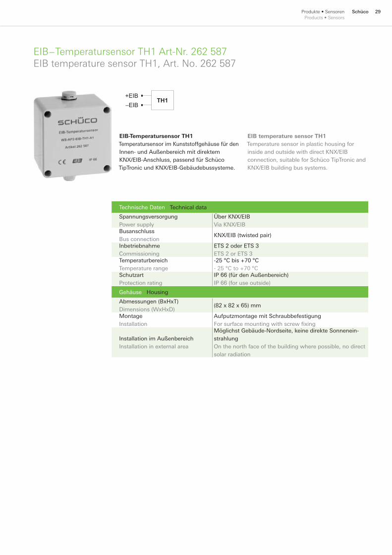
EIB−Temperatursensor TH1 Art-Nr. 262 587EIB temperature sensor TH1, Art. No. 262 587
Technische Daten Technical data
Spannungsversorgung Power supply
Über KNX/EIB Via KNX/EIB
Busanschluss Bus connection
KNX/EIB (twisted pair)
Inbetriebnahme Commissioning
ETS 2 oder ETS 3 ETS 2 or ETS 3
Temperaturbereich Temperature range
-25 °C bis +70 °C - 25 °C to +70 °C
Schutzart Protection rating
IP 66 (für den Außenbereich) IP 66 (for use outside)
Gehäuse Housing
Abmessungen (BxHxT) Dimensions (WxHxD)
(82 x 82 x 65) mm
Montage Installation
Aufputzmontage mit Schraubbefestigung For surface mounting with screw fixing
Installation im Außenbereich Installation in external area
Möglichst Gebäude-Nordseite, keine direkte Sonnenein-strahlung On the north face of the building where possible, no direct solar radiation
+EIB−EIB
TH1
EIB-Temperatursensor TH1Temperatursensor im Kunststoffgehäuse für den Innen- und Außenbereich mit direktem KNX/EIB-Anschluss, passend für Schüco TipTronic und KNX/EIB-Gebäudebussysteme.
EIB temperature sensor TH1Temperature sensor in plastic housing for inside and outside with direct KNX/EIB connection, suitable for Schüco TipTronic and KNX/EIB building bus systems.

30 Schüco Produkte • Funksystem Products • Radio-controlled system
Schüco AvanTec FunkgriffSchüco AvanTec radio-controlled handle
Technische Daten Technical data
Frequenz Frequency
868 MHz
Anzahl der Kanäle Number of channels
1
Stromversorgung Power supply
Batteriebetrieb 3 x Typ CR 1632 Battery operation: 3 x CR 1632
Umgebungstemperatur Ambient temperature
0 °C bis +50 °C 0 °C to +50 °C
Schutzart Protection rating
IP 22
Montage Installation
Kammergetriebe 23 mm Cavity-fitted gearbox 23 mm
Oberfläche Surface finish Art.-Nr. Art. No.
EV 1 247 574 RAL 9005 247 575 RAL 9010 247 576 RAL 9016 247 577 Inox-Look 247 578
Schüco AvanTec FunkgriffFür Schüco Kammergetriebe 23 mm, zur Ansteuerung von Schüco TipTronic Fenstern in Verbindung mit Funkempfänger oder externen, elektrischen Verbrauchern in Verbindung mit externem Funkempfänger (z.B. Schüco Raffstore).
Schüco AvanTec radio-controlled handleFor Schüco cavity-fitted gearbox 23 mm, for operating the Schüco TipTronic windows in conjunction with a radio receiver or external electrical consumers in conjunction with an external radio receiver (e.g. Schüco external blinds).

31SchücoProdukte • Funksystem Products • Radio-controlled system
Schüco AvanTec Funkgriff DesignSchüco AvanTec feature radio-controlled handle
Technische Daten Technical data
Frequenz Frequency
868 MHz
Anzahl der Kanäle Number of channels
1
Stromversorgung Power supply
Batteriebetrieb 3 x Typ CR 1632 Battery operation: 3 x CR 1632
Umgebungstemperatur Ambient temperature
0 °C bis +50 °C 0 °C to +50 °C
Schutzart Protection rating
IP 22
Montage Installation
Kammergetriebe 23 mm Cavity-fitted gearbox 23 mm
Oberfläche Surface finish Art.-Nr. Art. No.
EV 1 247 582 RAL 9005 247 583 RAL 9010 247 584 RAL 9016 247 585 Inox-Look 247 586
Schüco AvanTec Funkgriff DesignFür Schüco Kammergetriebe 23 mm, zur Ansteuerung von Schüco TipTronic Fenstern in Verbindung mit Funkempfänger oder externen, elektrischen Verbrauchern in Verbindung mit externem Funkempfänger (z.B. Schüco Raffstore).
Schüco AvanTec feature radio-controlled handleFor Schüco cavity-fitted gearbox 23 mm, for operating the Schüco TipTronic windows in conjunction with a radio receiver or external electrical consumers in conjunction with an external radio receiver (e.g. Schüco external blinds).
32 Schüco Produkte • Funksystem Products • Radio-controlled system
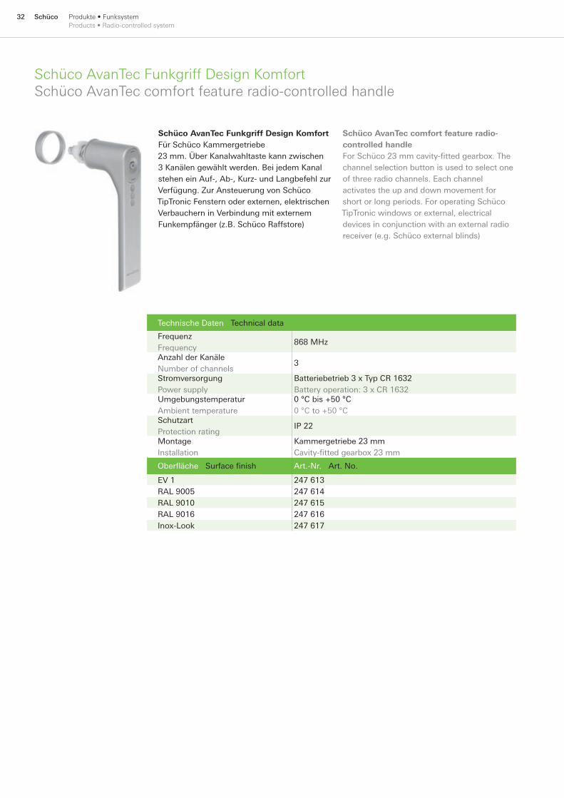
Schüco AvanTec Funkgriff Design KomfortSchüco AvanTec comfort feature radio-controlled handle
Technische Daten Technical data
Frequenz Frequency
868 MHz
Anzahl der Kanäle Number of channels
3
Stromversorgung Power supply
Batteriebetrieb 3 x Typ CR 1632 Battery operation: 3 x CR 1632
Umgebungstemperatur Ambient temperature
0 °C bis +50 °C 0 °C to +50 °C
Schutzart Protection rating
IP 22
Montage Installation
Kammergetriebe 23 mm Cavity-fitted gearbox 23 mm
Oberfläche Surface finish Art.-Nr. Art. No.
EV 1 247 613 RAL 9005 247 614 RAL 9010 247 615 RAL 9016 247 616 Inox-Look 247 617
Schüco AvanTec Funkgriff Design KomfortFür Schüco Kammergetriebe 23 mm. Über Kanalwahltaste kann zwischen 3 Kanälen gewählt werden. Bei jedem Kanal stehen ein Auf-, Ab-, Kurz- und Langbefehl zur Verfügung. Zur Ansteuerung von Schüco TipTronic Fenstern oder externen, elektrischen Verbauchern in Verbindung mit externem Funkempfänger (z.B. Schüco Raffstore)
Schüco AvanTec comfort feature radio-controlled handleFor Schüco 23 mm cavity-fitted gearbox. The channel selection button is used to select one of three radio channels. Each channel activates the up and down movement for short or long periods. For operating Schüco TipTronic windows or external, electrical devices in conjunction with an external radio receiver (e.g. Schüco external blinds)
33SchücoProdukte • Funksystem Products • Radio-controlled system
Fernbedienung 1-Kanal 868 MHz Art-Nr. 262 634remote control 1-channel 868 MHz Art. No. 262 634
Technische Daten Technical data
Frequenz Frequency
868 MHz
Anzahl der Kanäle Number of channels
1
Stromversorgung Power supply
Batteriebetrieb 1 x Typ CR 2450 Battery operation: 1 x CR 2450
Spannungsversorgung Power supply
3 V
Gewicht Weight
0,025 kg
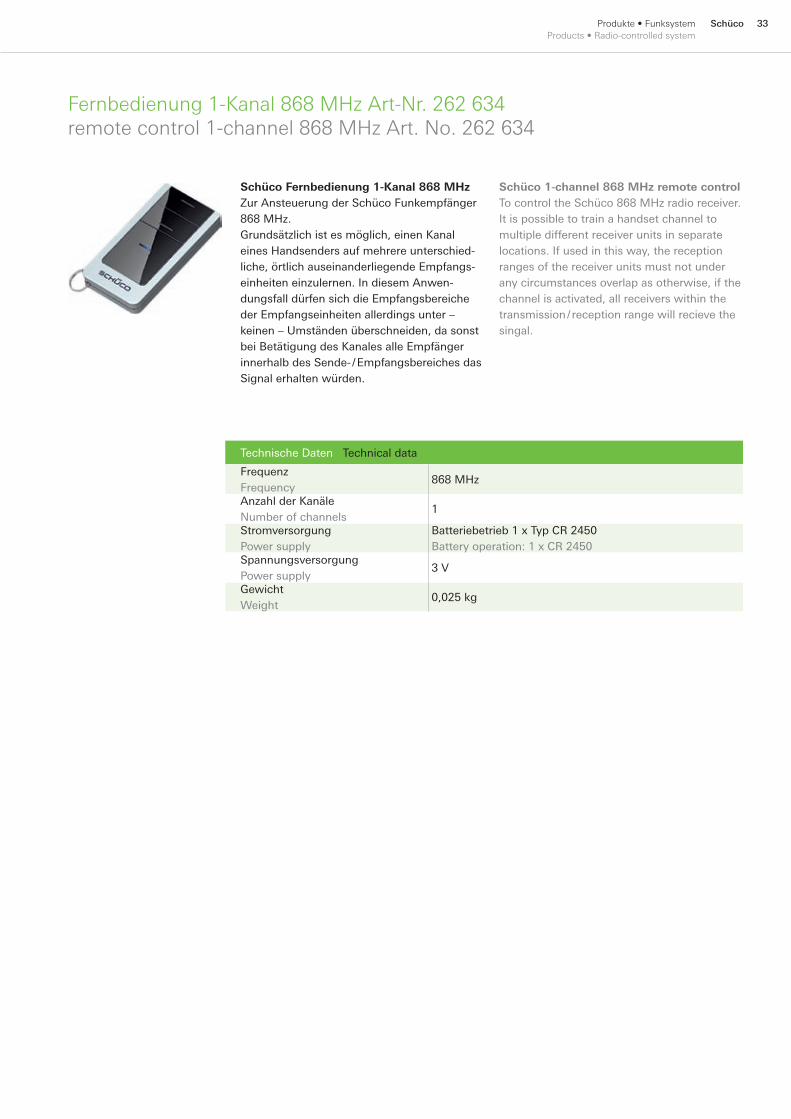
Schüco Fernbedienung 1-Kanal 868 MHzZur Ansteuerung der Schüco Funkempfänger 868 MHz.Grundsätzlich ist es möglich, einen Kanal eines Handsenders auf mehrere unterschied-liche, örtlich auseinanderliegende Empfangs-einheiten einzulernen. In diesem Anwen-dungsfall dürfen sich die Empfangsbereiche der Empfangseinheiten allerdings unter – keinen – Umständen überschneiden, da sonst bei Betätigung des Kanales alle Empfänger innerhalb des Sende- / Empfangsbereiches das Signal erhalten würden.
Schüco 1-channel 868 MHz remote controlTo control the Schüco 868 MHz radio receiver.It is possible to train a handset channel to multiple different receiver units in separate locations. If used in this way, the reception ranges of the receiver units must not under any circumstances overlap as otherwise, if the channel is activated, all receivers within the transmission / reception range will recieve the singal.
34 Schüco Produkte • Funksystem Products • Radio-controlled system
Fernbedienung 3-Kanal 868 MHz Art-Nr. 262 654Remote control 3-channel 868 MHz Art. No. 262 654
Technische Daten Technical data
Frequenz Frequency
868 MHz
Anzahl der Kanäle Number of channels
3
Stromversorgung Power supply
Batteriebetrieb 3x Typ CR 1632 Battery operation: 3 x CR 1632
Spannungsversorgung Power supply
3 V
Gewicht Weight
0,053 kg
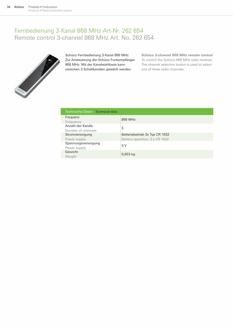
Schüco Fernbedienung 3-Kanal 868 MHzZur Ansteuerung der Schüco Funkempfänger 868 MHz. Mit der Kanalwahltaste kann zwischen 3 Schaltkanälen gewählt werden.
Schüco 3-channel 868 MHz remote controlTo control the Schüco 868 MHz radio receiver. The channel selection button is used to select one of three radio channels.
35SchücoProdukte • Funksystem Products • Radio-controlled system
Funkempfänger extern FE1−UP Art-Nr. 262 653Radio receiver external FE1−UP Art. No. 262 653
Technische Daten Technical data
Spannungsversorgung Power supply
DC 6 bis 24 V; AC 8,5 bis 24 V DC 6 to 24 V; AC 8.5 to 24 V
Stromaufnahme Power consumption
Max. 30 mA
Frequenz Frequency 868 MHz Anzahl der Kanäle Number of channels
1
Schutzart nach EN 60529 Protection rating in accordance with EN 60529
IP 22 (im eingebauten Zustand) IP 22 (when installed)
Relais-Ausgänge Relay outputs
Min. 20 mA bei AC/DC 24 V, Max. 0,5 mA bei AC/DC 24 V, Max. Schaltspannung AC/DC 30 V Min. 20 mA with AC/DC 24 V, Max. 0.5 mA with AC/DC 24 V, Max. switching voltage AC/DC 30 V
Relais-Schaltzeiten Relay switching times
Kurzbefehl: (100 ms, 250 ms, 500 ms) Langbefehl: (1 s, 2,5 s, 30 s, 60 s, 90 s, 120 s Dauerbetrieb) Short instruction: (100 ms, 250 ms, 500 ms) Long instruction: (1 s, 2.5 s, 30 s, 60 s, 90 s, 120 s continuous operation)
Gehäuse Housing
Abmessungen (B x H x T) Dimensions (W x H x D)
(40 x 40 x 26) mm
Montage Installation
In UP-Dose In flush-mounted socket
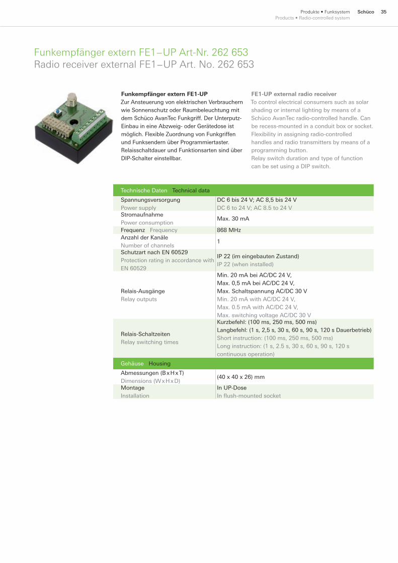
Funkempfänger extern FE1-UPZur Ansteuerung von elektrischen Verbrauchern wie Sonnenschutz oder Raumbeleuchtung mit dem Schüco AvanTec Funkgriff. Der Unterputz-Einbau in eine Abzweig- oder Gerätedose ist möglich. Flexible Zuordnung von Funkgriffen und Funksendern über Programmiertaster. Relaisschaltdauer und Funktionsarten sind über DIP-Schalter einstellbar.
FE1-UP external radio receiverTo control electrical consumers such as solar shading or internal lighting by means of a Schüco AvanTec radio-controlled handle. Can be recess-mounted in a conduit box or socket. Flexibility in assigning radio-controlled handles and radio transmitters by means of a programming button. Relay switch duration and type of function can be set using a DIP switch.
36 Schüco Produkte • Funksystem Products • Radio-controlled system
Funkempfänger FE1−PIRadio receiver FE1−PI
Technische Daten Technical data
Spannungsversorgung Power supply
DC 5 V über Steuergerät DC 5 V above control unit
Stromaufnahme Power consumption
Max. 20 mA
Frequenz Frequency
868 MHz
Anzahl der Kanäle Number of channels
1
Steckverbinder X21, X22 Push-in connectors X21, X22
JST Stecker JST plug
Schutzart nach EN 60529 Protection rating in accordance with EN 60529
IP 22 (im eingebauten Zustand im Profi l) IP 22 (when installed in the profi le)
Betriebsart Operation type
S1 Dauerbetrieb S1 continuous operation
Montage Installation
Verdeckt liegend im Schüco TipTronic Flügelprofi l Concealed in Schüco TipTronic vent profi le
Elemente Elements Art.-Nr. Art. No. LS/VE/PU Art.-Nr. Art. No. RS/VE/PU
- 262 625 1
262 703 1 262 704 1
- 262 704 1
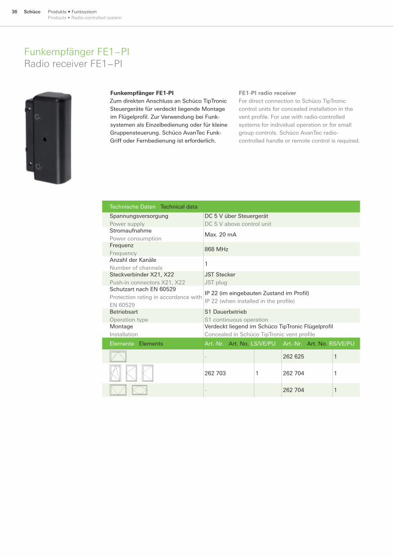
Funkempfänger FE1-PIZum direkten Anschluss an Schüco TipTronic Steuergeräte für verdeckt liegende Montage im Flügelprofi l. Zur Verwendung bei Funk-systemen als Einzelbedienung oder für kleine Gruppensteuerung. Schüco AvanTec Funk-Griff oder Fernbedienung ist erforderlich.
FE1-PI radio receiverFor direct connection to Schüco TipTronic control units for concealed installation in the vent profi le. For use with radio-controlled systems for individual operation or for small group controls. Schüco AvanTec radio-controlled handle or remote control is required.
37SchücoProdukte • Bedienen und AnzeigenProducts • Operation and display
ControlPanelControlPanel
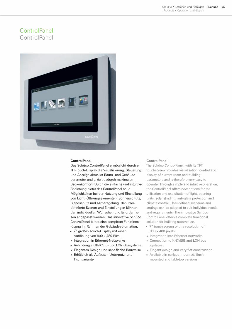
ControlPanelDas Schüco ControlPanel ermöglicht durch ein TFT-Touch-Display die Visualisierung, Steuerung und Anzeige aktueller Raum- und Gebäude-parameter und erzielt dadurch maximalen Bedienkomfort. Durch die einfache und intuitive Bedienung bietet das ControlPanel neue Möglichkeiten bei der Nutzung und Einstellung von Licht, Öffnungselementen, Sonnenschutz, Blendschutz und Klimaregelung. Benutzer-definierte Szenen und Einstellungen können den individuellen Wünschen und Erfordernis-sen angepasst werden. Das innovative Schüco ControlPanel bietet eine komplette Funktions-lösung im Rahmen der Gebäudeautomation.
7” großes Touch-Display mit einer Auflösung von 800 x 480 PixelIntegration in Ethernet-NetzwerkeAnbindung an KNX/EIB- und LON-BussystemeElegantes Design und sehr flache BauweiseErhältlich als Aufputz-, Unterputz- und Tischvariante
■
■■■■
ControlPanelThe Schüco ControlPanel, with its TFT touchscreen provides visualisation, control and display of current room and building parameters and is therefore very easy to operate. Through simple and intuitive operation, the ControlPanel offers new options for the utilisation and exploitation of light, opening units, solar shading, anti-glare protection and climate control. User-defined scenarios and settings can be adapted to suit individual needs and requirements. The innovative Schüco ControlPanel offers a complete functional solution for building automation.
7” touch screen with a resolution of 800 x 480 pixelsIntegration into Ethernet networksConnection to KNX/EIB and LON bus systemsElegant design and very flat constructionAvailable in surface-mounted, flush-mounted and tabletop versions
■
■■
■■
38 Schüco Produkte • Bedienen und AnzeigenProducts • Operation and display
ControlPanelControlPanel
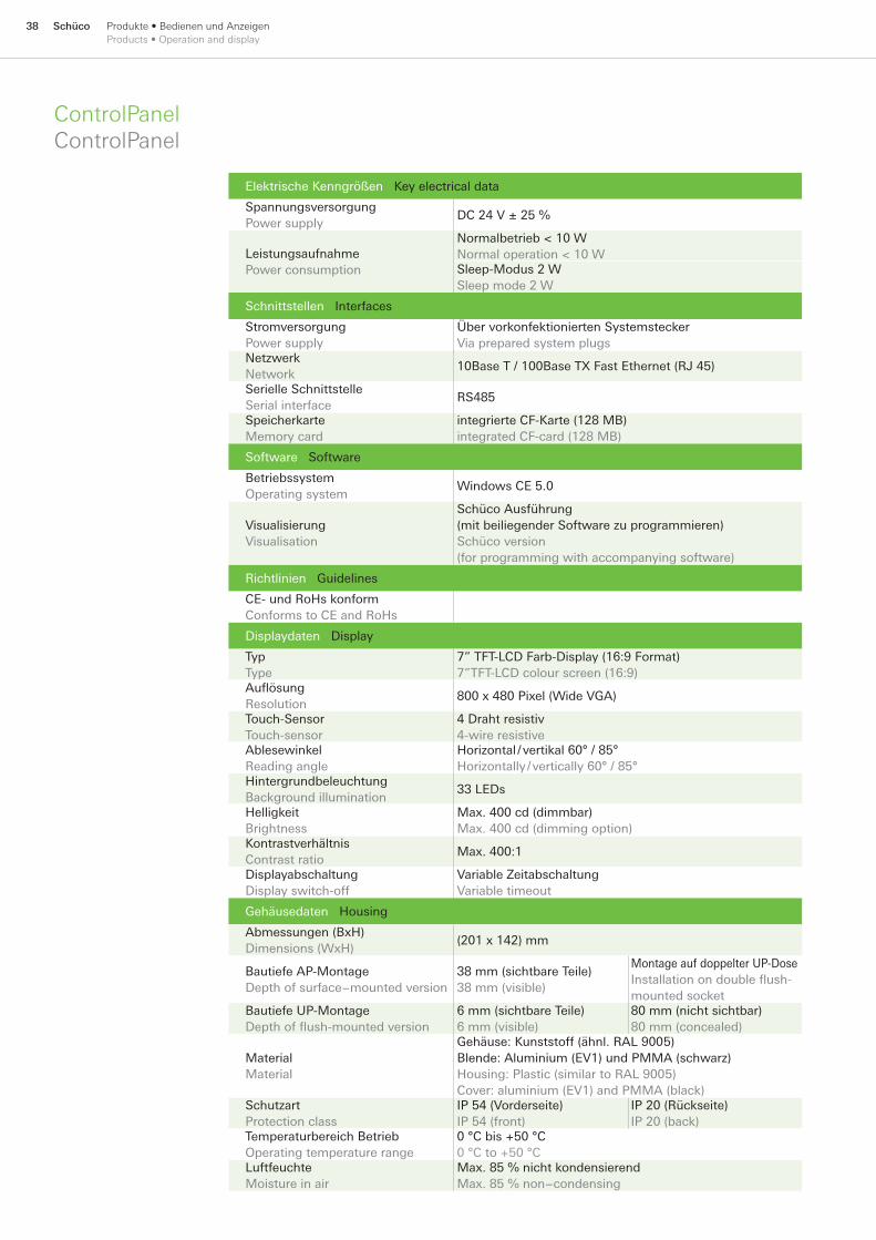
Elektrische Kenngrößen Key electrical data
SpannungsversorgungPower supply
DC 24 V ± 25 %
LeistungsaufnahmePower consumption
Normalbetrieb < 10 WNormal operation < 10 WSleep-Modus 2 WSleep mode 2 W
Schnittstellen Interfaces
StromversorgungPower supply
Über vorkonfektionierten SystemsteckerVia prepared system plugs
NetzwerkNetwork
10Base T / 100Base TX Fast Ethernet (RJ 45)
Serielle SchnittstelleSerial interface
RS485
SpeicherkarteMemory card
integrierte CF-Karte (128 MB)integrated CF-card (128 MB)
Software Software
BetriebssystemOperating system
Windows CE 5.0
VisualisierungVisualisation
Schüco Ausführung (mit beiliegender Software zu programmieren)Schüco version (for programming with accompanying software)
Richtlinien Guidelines
CE- und RoHs konformConforms to CE and RoHs
Displaydaten Display
TypType
7” TFT-LCD Farb-Display (16:9 Format)7”TFT-LCD colour screen (16:9)
AuflösungResolution
800 x 480 Pixel (Wide VGA)
Touch-SensorTouch-sensor
4 Draht resistiv4-wire resistive
AblesewinkelReading angle
Horizontal / vertikal 60° / 85°Horizontally / vertically 60° / 85°
HintergrundbeleuchtungBackground illumination
33 LEDs
HelligkeitBrightness
Max. 400 cd (dimmbar)Max. 400 cd (dimming option)
KontrastverhältnisContrast ratio
Max. 400:1
DisplayabschaltungDisplay switch-off
Variable ZeitabschaltungVariable timeout
Gehäusedaten Housing
Abmessungen (BxH)Dimensions (WxH)
(201 x 142) mm
Bautiefe AP-MontageDepth of surface−mounted version
38 mm (sichtbare Teile)38 mm (visible)
Montage auf doppelter UP-DoseInstallation on double flush-mounted socket
Bautiefe UP-MontageDepth of flush-mounted version
6 mm (sichtbare Teile)6 mm (visible)
80 mm (nicht sichtbar) 80 mm (concealed)
MaterialMaterial
Gehäuse: Kunststoff (ähnl. RAL 9005) Blende: Aluminium (EV1) und PMMA (schwarz)Housing: Plastic (similar to RAL 9005) Cover: aluminium (EV1) and PMMA (black)
SchutzartProtection class
IP 54 (Vorderseite)IP 54 (front)
IP 20 (Rückseite)IP 20 (back)
Temperaturbereich BetriebOperating temperature range
0 °C bis +50 °C0 °C to +50 °C
LuftfeuchteMoisture in air
Max. 85 % nicht kondensierendMax. 85 % non−condensing
39SchücoProdukte • Bedienen und AnzeigenProducts • Operation and display
ControlPanel SoftwareControlPanel Software
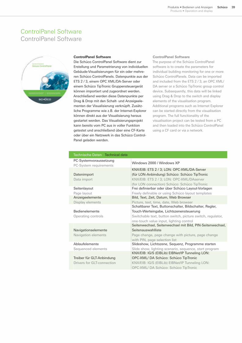
ControlPanel Software Die Schüco ControlPanel Software dient zur Erstellung und Parametrierung von individuellen Gebäude-Visualisierungen für ein oder mehre-ren Schüco ControlPanels. Datenpunkte aus der ETS 2 / 3, einem OPC XML/DA-Server oder einem Schüco TipTronic Gruppensteuergerät können importiert und zugeordnet werden. Anschließend werden diese Datenpunkte per Drag & Drop mit den Schalt- und Anzeigeele-menten der Visualisierung verknüpft. Zusätz-liche Programme wie z.B. der Internet-Explorer können direkt aus der Visualisierung heraus gestartet werden. Das Visualisierungsprojekt kann bereits vom PC aus in voller Funktion getestet und anschließend über eine CF-Karte oder über ein Netzwerk in das Schüco Control-Panel geladen werden.
Technische Daten Technical data
PC-SystemvoraussetzungPC-System requirements
Windows 2000 / Windows XP
DatenimportData import
KNX/EIB: ETS 2 / 3; LON: OPC-XML/DA-Server (für LON-Anbindung) Schüco: Schüco TipTronicKNX/EIB: ETS 2 / 3; LON: OPC-XML/DAserver (for LON connection) Schüco: Schüco TipTronic
SeitenlayoutPage layout
Frei defi nierbar oder über Schüco Layout-VorlagenFreely defi nable or using Schüco layout templates
AnzeigeelementeDisplay elements
Bild, Text, Zeit, Datum, Web BrowserPicture, text, time, date, Web browser
BedienelementeOperating controls
Schaltbarer Text, Buttonschalter, Bildschalter, Regler, Touch-Werteingabe, LichtszenensteuerungSwitchable text, button switch, picture switch, regulator, one-touch value input, lighting control
NavigationselementeNavigation elements
Seitenwechsel, Seitenwechsel mit Bild, PIN-Seitenwechsel, SeitenauswahllistePage change, page change with picture, page change with PIN, page selection list
AblaufelementeSequenced elements
Slideshow, Lichtszene, Sequenz, Programme startenSlide show, lighting scenario, sequence, start program
Treiber für GLT-AnbindungDrivers for GLT-connection
KNX/EIB: IG/S (EIBLib) EIBNet/IP Tunneling LON: OPC-XML/ DA Schüco: Schüco TipTronicKNX/EIB: IG/S (EIBLib) EIBNet/IP Tunneling LON: OPC-XML/ DA Schüco: Schüco TipTronic
ControlPanel Software The purpose of the Schüco ControlPanel software is to create the parameters for individual building monitoring for one or more Schüco ControlPanels. Data can be imported and included from the ETS 2 / 3, an OPC XML/DA server or a Schüco TipTronic group control device. Subsequently, this data will be linked using Drag & Drop to the switch and display elements of the visualisation program. Additional programs such as Internet Explorer can be started directly from the visualisation program. The full functionality of the visualisation project can be tested from a PC and then loaded into the Schüco ControlPanel using a CF card or via a network.

40 Schüco Produkte • Bedienen und AnzeigenProducts • Operation and display
ControlPanel Bestell- und PlanungshilfeControlPanel ordering and planning aid
Artikelbezeichnung Article description UP-Variante
Flush-mounted versions
AP-VarianteSurface-mounted
version
Tisch-VarianteTabletop versinos
Art.-Nr.Art. No.
ControlPanelBlende im Schüco-Design, CF-Speicherkarte mit Standard-Visualisierung (ohne Funktionsverknüpfungen) inkl. EinschaltzeitControlPanelSchüco Design Fascia, CF memory card with standard visualiation (without function links) incl. Runtimer
262 728
ControlPanelBlende im Schüco-Design, CF-Speicherkarte mit Standard-Visualisierung (ohne Funktionsverknüpfungen) inkl. EinschaltzeitControlPanelSchüco Design Fascia, CF memory card with standard visualiation (without function links) incl. Runtimer
262 729
Aufstellvorrichtungzum Aufstellen des ControlPanels auf z. B. einem TischOpening devicefor opening the control panel on a table, for example
262 735
Netzteil DC 24 V Power pack DC 24 V
262 497
NetzteilDC 24 V für Steckdose AC 230 V, Leitung zum ControlPanel inklusivePower packDC 24 V for socket AC 230 V, cable for control panel included
* 262 650
NetzteilDC 24 V für UnterputzdosePower packDC 24 V for flush-mounted socket
262 670
Ethernetleitungzur Anbindung an ein NetzwerkEthernet cablefor connecting to a network
262 753
Ethernetleitung crossoverzur Inbetriebnahme mit dem LaptopEthernet cable crossoverfor connecting to a laptop
262 754
Buskoppler Ethernet - EIB 1Linienkoppler zur Anbindung einer einzelnen KNX/EIB-LinieEthernet BUS connector EIB 1Line couple for connecting a single KNX/EIB line
OptionalOptional
OptionalOptional
OptionalOptional
262 734
Buskoppler Ethernet - EIB 2 (230 V)Bereichskoppler zur Anbindung mehrerer KNX/EIB-Linien und BereicheEthernet BUS connector EIB 2 (230 V)Group coupler for connection to several KNX/EIB lines and areas
OptionalOptional
OptionalOptional
OptionalOptional
262 755
LON OPC XML/ DA ServerZur Anbindung des ControlPanels an ein LON-NetzwerkLON OPC XML/OA ServerFor connecting the ControlPanel to a LON network
OptionalOptional
OptionalOptional
OptionalOptional
262 756
Buskoppler Ethernet RS485Zur direkten Anbindung von mehreren Schüco TipTronic-Fenstergruppen an das ControlPanelEthernet bus coupler RS485For connecting several Schüco TipTronic window groups directly to the ControlPanel
OptionalOptional
OptionalOptional
OptionalOptional
242 559
*Für die Tischvariante des ControlPanels kann nur das Steckernetzteil 262 650 verwendet werden. The table-top version of the ControlPanel will only take the plug-in power pack 262 650.

41SchücoProdukte • Zubehör Products • Accessories
Einfachtaster ET Art-Nr. 262 641ET single momentary contact switch, Art. No. 262 641
Lüftungstaster LT Art-Nr. 262 642LT ventilation momentary contact switch, Art. No. 262 642
Einfachtaster ETFür Unterputzmontage.Austauschbares Beschrif-tungsfeld. Zum Anschluss am Gruppensteuergerät Klemme 15, 16 oder I/O-Modul.
ET single momentary contact switchFor flush mounting.Interchangeable label space. For connecting to group control unit terminal 15, 16 or I/O module.
Technische Daten Technical data
Ausführung Design
Doppelwippe ohne Verriegelung Double rocker without lock
Beschriftung Labels
Symbole AUF-ZU OPEN and CLOSE symbols
Kontaktmaterial Contact material
Gold Gold
Anwendung Use
Fenster AUF-STOPP-ZU Window OPEN - STOP - CLOSED
Montage Installation
UP oder in AP in Gehäuse 262 645 Flush-mounted or surface-mounted in housing 262 645
Lüftungstaster LTFür Unterputzmontage. Austauschbares Beschrif-tungsfeld. Zum Anschluss am Gruppensteuergerät Klemme 6, 7, 8 oder I/O-Modul.
LT Ventilation momentary contact switchFor flush mounting. Interchangeable label space. For connecting to group control unit terminal 6, 7, 8 or I/O module.
Technische Daten Technical data
Ausführung Design
Einzelwippe Single rocker
Kontaktmaterial Contact material
Gold Gold
Anwendung Use
Zeitlüften, Natürliches Lüften, Entriegelung Timed ventilation, natural ventilation, unlocking
Montage Installation
UP oder in AP in Gehäuse 262 645 Flush-mounted or surface-mounted in housing 262 645

42 Schüco Produkte • Zubehör Products • Accessories
Schlüsseltaster ET Art-Nr. 262 961ET key-operated switch, Art. No. 262 961
Technische Daten Technical data
Ausführung Design
Doppeltaster AUF - O - ZU Double momentary contact switch OPEN - 0 - CLOSED
Anwendung Use
Fenster AUF - ZU, Sonnenschutz- und Lüftungsmotoren AC 230 VWindow OPEN - CLOSED, solar shading and ventilation motors AC 230 V
Montage Installation
UP oder in AP in Gehäuse 262 645 Flush-mounted or surface-mounted in housing 262 645
Schlüsseltaster ET Für Unterputzmontage. Passend für Schüco TipTronic Gruppensteuergerät und I/O-Modul. Austauschbares Beschriftungsfeld. Zum Anschluss am Gruppensteu-ergerät Klemme 15, 16 oder I/O-Modul.
ET key-operated switch For flush mounting. Suitable for Schüco TipTronic group control unit and I/O module. Interchangeable label space. For connecting to group control unit terminal 15, 16 or I/O module.
Schlüsseltaster LT Art-Nr. 262 962LT key-operated switch, Art. No. 262 962
Schlüsseltaster LTFür Unterputzmontage. Passend für Schüco TipTronic Gruppensteuergerät und I/O-Modul. Austauschbares Beschriftungsfeld. Zum Anschluss am Gruppensteu-ergerät Klemme 6, 7, 8 oder I/O-Modul.
LT key-operated switchFor flush mounting. Suitable for Schüco TipTronic group control unit and I/O module. Interchangeable label space. For connecting to group control unit terminal 6, 7, 8 or I/O module.
Technische Daten Technical data
Ausführung Design
Einfachtaster EIN-AUS Single momentary contact switch ON - OFF
Anwendung Use
Zeitlüften, Natürliches Lüften, Entriegelung Timed ventilation, natural ventilation, unlocking
Montage Installation
UP oder in AP in Gehäuse 262 645 Flush-mounted or surface-mounted in housing 262 645
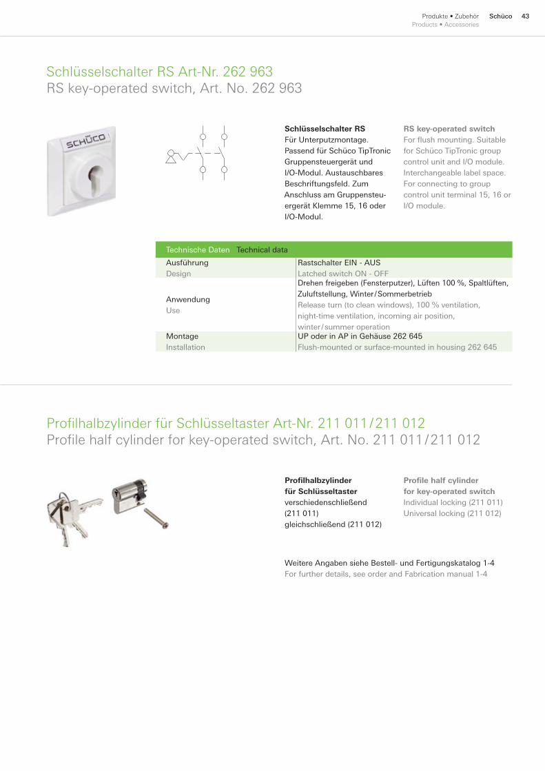
43SchücoProdukte • Zubehör Products • Accessories
Schlüsselschalter RS Art-Nr. 262 963 RS key-operated switch, Art. No. 262 963
Technische Daten Technical data
Ausführung Design
Rastschalter EIN - AUS Latched switch ON - OFF
Anwendung Use
Drehen freigeben (Fensterputzer), Lüften 100 %, Spaltlüften, Zuluftstellung, Winter / Sommerbetrieb Release turn (to clean windows), 100 % ventilation, night-time ventilation, incoming air position, winter / summer operation
Montage Installation
UP oder in AP in Gehäuse 262 645 Flush-mounted or surface-mounted in housing 262 645
Profilhalbzylinder für Schlüsseltaster Art-Nr. 211 011 / 211 012 Profile half cylinder for key-operated switch, Art. No. 211 011 / 211 012
Schlüsselschalter RSFür Unterputzmontage. Passend für Schüco TipTronic Gruppensteuergerät und I/O-Modul. Austauschbares Beschriftungsfeld. Zum Anschluss am Gruppensteu-ergerät Klemme 15, 16 oder I/O-Modul.
RS key-operated switchFor flush mounting. Suitable for Schüco TipTronic group control unit and I/O module. Interchangeable label space. For connecting to group control unit terminal 15, 16 or I/O module.
Profilhalbzylinder für Schlüsseltaster verschiedenschließend (211 011) gleichschließend (211 012)
Weitere Angaben siehe Bestell- und Fertigungskatalog 1-4 For further details, see order and Fabrication manual 1-4
Profile half cylinder for key-operated switchIndividual locking (211 011)Universal locking (211 012)
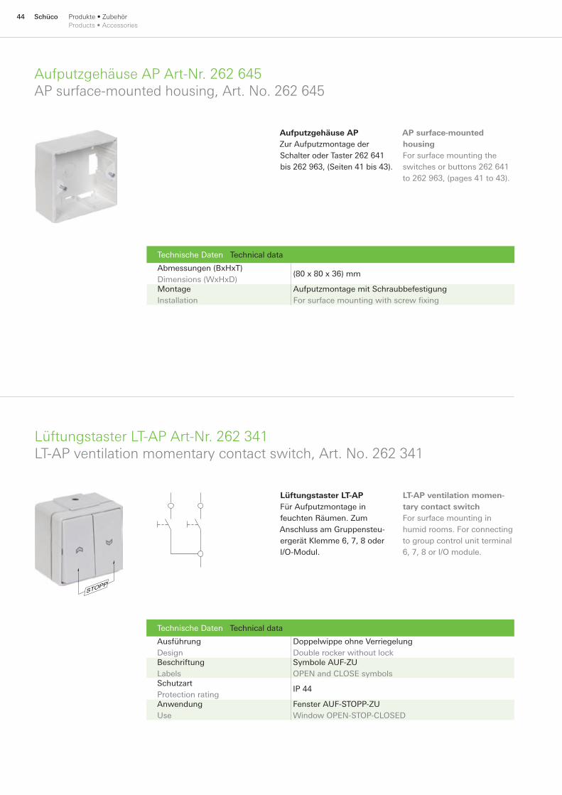
44 Schüco Produkte • Zubehör Products • Accessories
Aufputzgehäuse AP Art-Nr. 262 645 AP surface-mounted housing, Art. No. 262 645
Lüftungstaster LT-AP Art-Nr. 262 341 LT-AP ventilation momentary contact switch, Art. No. 262 341
Technische Daten Technical data
Ausführung Design
Doppelwippe ohne Verriegelung Double rocker without lock
Beschriftung Labels
Symbole AUF-ZU OPEN and CLOSE symbols
Schutzart Protection rating
IP 44
Anwendung Use
Fenster AUF-STOPP-ZU Window OPEN-STOP-CLOSED
Aufputzgehäuse APZur Aufputzmontage der Schalter oder Taster 262 641 bis 262 963, (Seiten 41 bis 43).
AP surface-mounted housingFor surface mounting the switches or buttons 262 641 to 262 963, (pages 41 to 43).
Lüftungstaster LT-APFür Aufputzmontage in feuchten Räumen. Zum Anschluss am Gruppensteu-ergerät Klemme 6, 7, 8 oder I/O-Modul.
LT-AP ventilation momen-tary contact switchFor surface mounting in humid rooms. For connecting to group control unit terminal 6, 7, 8 or I/O module.
Technische Daten Technical data
Abmessungen (BxHxT) Dimensions (WxHxD)
(80 x 80 x 36) mm
Montage Installation
Aufputzmontage mit Schraubbefestigung For surface mounting with screw fixing

45SchücoProdukte • Zubehör Products • Accessories
Schlüsselschalter Art-Nr. 262 572 Key-operated switch, Art. No. 262 572
Technische Daten Technical data
Montage Installation
In Dose In Ø 62 mm socket
Leitungstyp Cable type
2 seitiger Tastkontakt 2 sided touch contact
Funktion Function
Nicht rastend Continuous
Kontakte Contacts
2 Mikroschalter 2 microswitches
Kontaktart Contact type
Schließer Closer
Ausführung Design
Für Halbzylinder 10 / 30 For half cylinder 10 / 30
Schutzart Protection rating
IP 55
Oberfläche Surface finish
Naturfarben eloxiert Natural anodised
Schlüsselschalter UPFür Unterputzmontage. Passend für Schüco TipTronic Gruppensteuergerät und I/O-Modul.
Flush-mounted key-operated switchFor flush mounting. Suitable for Schüco TipTronic group control unit and I/O module.
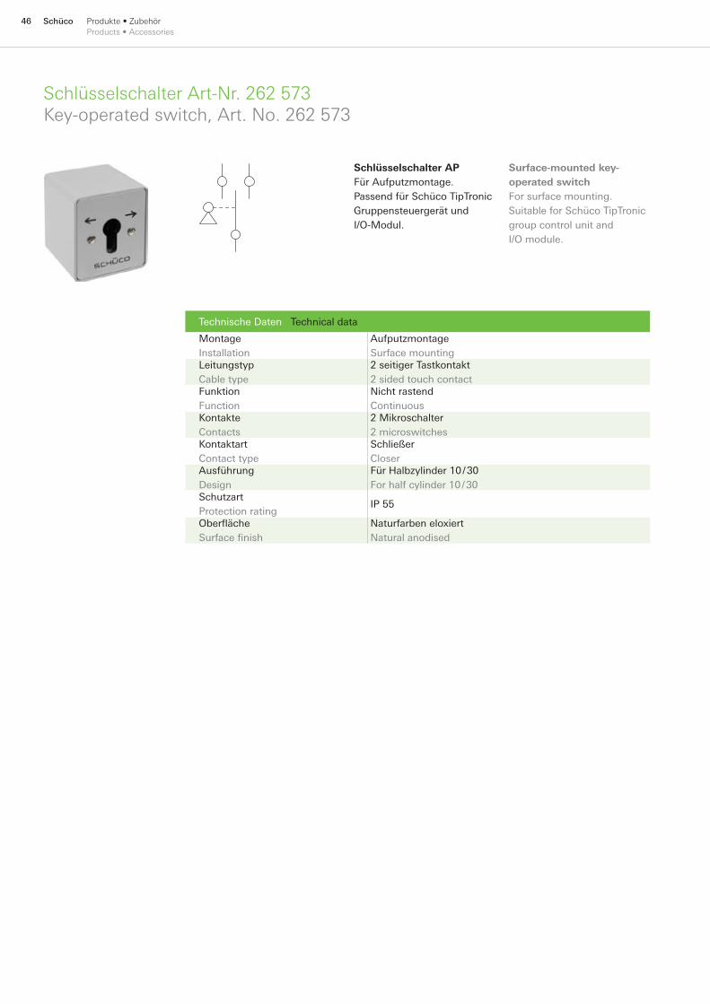
46 Schüco Produkte • Zubehör Products • Accessories
Schlüsselschalter Art-Nr. 262 573 Key-operated switch, Art. No. 262 573
Technische Daten Technical data
Montage Installation
Aufputzmontage Surface mounting
Leitungstyp Cable type
2 seitiger Tastkontakt 2 sided touch contact
Funktion Function
Nicht rastend Continuous
Kontakte Contacts
2 Mikroschalter 2 microswitches
Kontaktart Contact type
Schließer Closer
Ausführung Design
Für Halbzylinder 10 / 30 For half cylinder 10 / 30
Schutzart Protection rating
IP 55
Oberfläche Surface finish
Naturfarben eloxiert Natural anodised
Schlüsselschalter APFür Aufputzmontage. Passend für Schüco TipTronic Gruppensteuergerät und I/O-Modul.
Surface-mounted key-operated switchFor surface mounting. Suitable for Schüco TipTronic group control unit and I/O module.
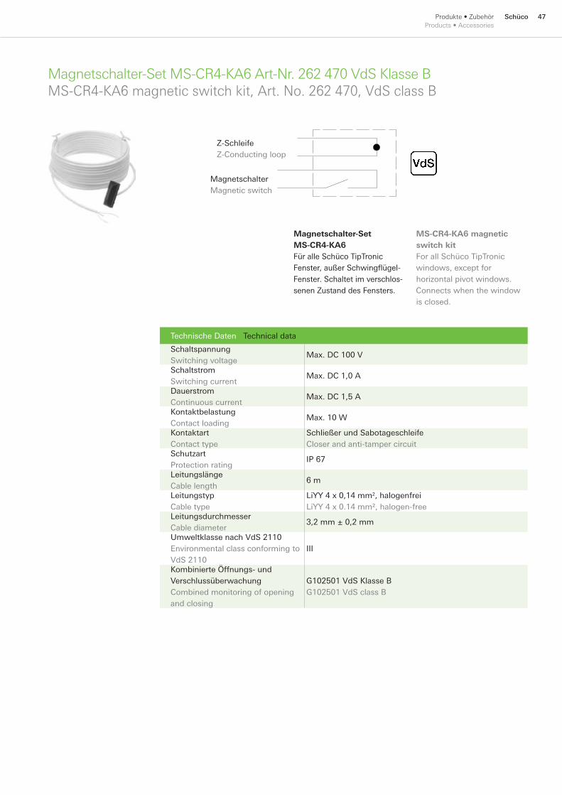
47SchücoProdukte • Zubehör Products • Accessories
Magnetschalter-Set MS-CR4-KA6 Art-Nr. 262 470 VdS Klasse B MS-CR4-KA6 magnetic switch kit, Art. No. 262 470, VdS class B
Technische Daten Technical data
Schaltspannung Switching voltage
Max. DC 100 V
Schaltstrom Switching current
Max. DC 1,0 A
Dauerstrom Continuous current
Max. DC 1,5 A
Kontaktbelastung Contact loading
Max. 10 W
Kontaktart Contact type
Schließer und Sabotageschleife Closer and anti-tamper circuit
Schutzart Protection rating
IP 67
Leitungslänge Cable length
6 m
Leitungstyp Cable type
LiYY 4 x 0,14 mm2, halogenfrei LiYY 4 x 0.14 mm², halogen-free
Leitungsdurchmesser Cable diameter
3,2 mm ± 0,2 mm
Umweltklasse nach VdS 2110 Environmental class conforming to VdS 2110
III
Kombinierte Öffnungs- und Verschlussüberwachung Combined monitoring of opening and closing
G102501 VdS Klasse B G102501 VdS class B
Magnetschalter-Set MS-CR4-KA6Für alle Schüco TipTronic Fenster, außer Schwingflügel-Fenster. Schaltet im verschlos-senen Zustand des Fensters.
MS-CR4-KA6 magnetic switch kitFor all Schüco TipTronic windows, except for horizontal pivot windows. Connects when the window is closed.
Magnetschalter Magnetic switch
Z-Schleife Z-Conducting loop
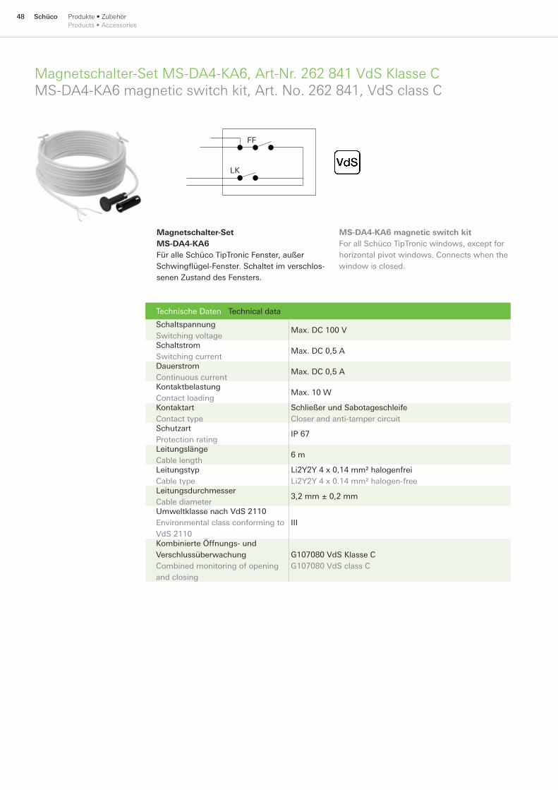
48 Schüco Produkte • Zubehör Products • Accessories
Technische Daten Technical data
Schaltspannung Switching voltage
Max. DC 100 V
Schaltstrom Switching current
Max. DC 0,5 A
Dauerstrom Continuous current
Max. DC 0,5 A
Kontaktbelastung Contact loading
Max. 10 W
Kontaktart Contact type
Schließer und Sabotageschleife Closer and anti-tamper circuit
Schutzart Protection rating
IP 67
Leitungslänge Cable length
6 m
Leitungstyp Cable type
Li2Y2Y 4 x 0,14 mm² halogenfrei Li2Y2Y 4 x 0.14 mm² halogen-free
Leitungsdurchmesser Cable diameter
3,2 mm ± 0,2 mm
Umweltklasse nach VdS 2110 Environmental class conforming to VdS 2110
III
Kombinierte Öffnungs- und Verschlussüberwachung Combined monitoring of opening and closing
G107080 VdS Klasse C G107080 VdS class C
Magnetschalter-Set MS-DA4-KA6Für alle Schüco TipTronic Fenster, außer Schwingflügel-Fenster. Schaltet im verschlos-senen Zustand des Fensters.
FF
LK
MS-DA4-KA6 magnetic switch kitFor all Schüco TipTronic windows, except for horizontal pivot windows. Connects when the window is closed.
Magnetschalter-Set MS-DA4-KA6, Art-Nr. 262 841 VdS Klasse CMS-DA4-KA6 magnetic switch kit, Art. No. 262 841, VdS class C

49SchücoProdukte • Zubehör Products • Accessories
Aufputzgehäuse KV-AP12 Art-Nr. 262 498 KV-AP12 surface-mounted housing, Art. No. 262 498
Aufputzgehäuse KV-AP12Leergehäuse für Aufputzmontage, passend für EIB-Buskoppler, Gruppensteuergerät, Netzteil und LON-Buskoppler.
Gehäuse Housing
Abmessungen (B x H x T) Dimensions (W x H x D)
(250 x 200 x 122) mm
Einbauplatz Installation space
12 TE
Montage Installation
Schraubbefestigung Screw fixing
Farbe Colour
Grau Grey
Material Material
Thermoplast Thermoplastic
Schutzart Protection rating
IP 65
Gewicht Weight
1,23 kg
KV-AP12 surface-mounted housingEmpty housing for surface-mounting, suitable for EIB bus coupler, group control unit, power pack and LON bus coupler.
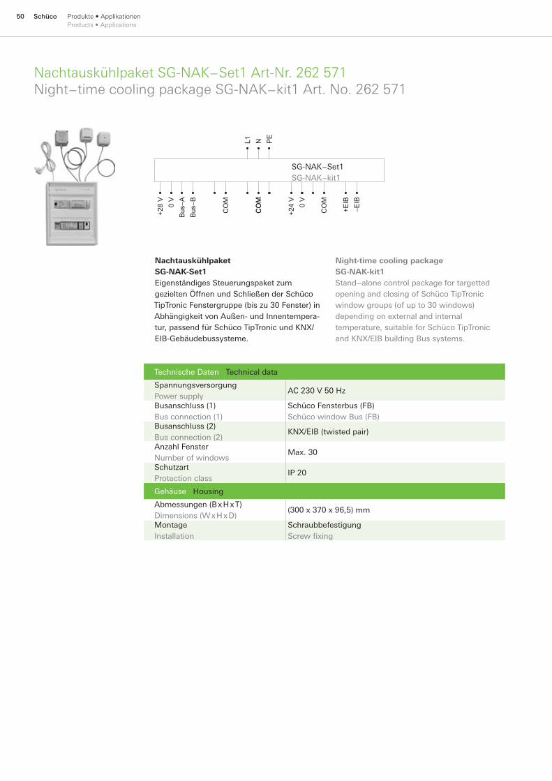
50 Schüco Produkte • Applikationen Products • Applications
Nachtauskühlpaket SG-NAK−Set1 Art-Nr. 262 571 Night−time cooling package SG-NAK−kit1 Art. No. 262 571
Technische Daten Technical data
Spannungsversorgung Power supply
AC 230 V 50 Hz
Busanschluss (1) Bus connection (1)
Schüco Fensterbus (FB) Schüco window Bus (FB)
Busanschluss (2) Bus connection (2)
KNX/EIB (twisted pair)
Anzahl Fenster Number of windows
Max. 30
Schutzart Protection class
IP 20
Gehäuse Housing
Abmessungen (B x H x T) Dimensions (W x H x D)
(300 x 370 x 96,5) mm
Montage Installation
Schraubbefestigung Screw fixing
SG-NAK−Set1 SG-NAK−kit1
+28
V 0
V B
us−A
Bus
−B
CO
M MO
CM
OC +24
V 0
V
CO
M
+EIB
−EIB
L1 N PE
Nachtauskühlpaket SG-NAK-Set1Eigenständiges Steuerungspaket zum gezielten Öffnen und Schließen der Schüco TipTronic Fenstergruppe (bis zu 30 Fenster) in Abhängigkeit von Außen- und Innentempera-tur, passend für Schüco TipTronic und KNX/EIB-Gebäudebussysteme.
Night-time cooling package SG-NAK-kit1Stand−alone control package for targetted opening and closing of Schüco TipTronic window groups (of up to 30 windows) depending on external and internal temperature, suitable for Schüco TipTronic and KNX/EIB building Bus systems.
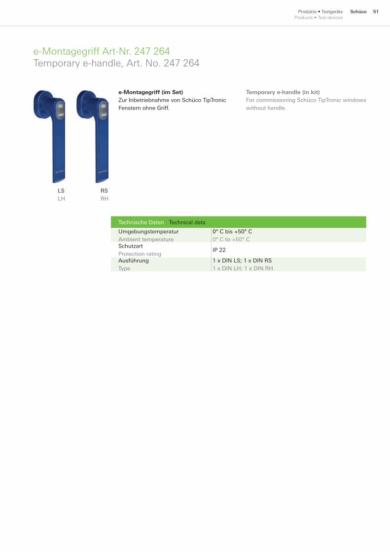
51SchücoProdukte • TestgeräteProducts • Test devices
e-Montagegriff Art-Nr. 247 264Temporary e-handle, Art. No. 247 264
Technische Daten Technical data
Umgebungstemperatur Ambient temperature
0° C bis +50° C 0° C to +50° C
Schutzart Protection rating
IP 22
Ausführung Type
1 x DIN LS; 1 x DIN RS 1 x DIN LH; 1 x DIN RH
e-Montagegriff (im Set)Zur Inbetriebnahme von Schüco TipTronic Fenstern ohne Griff.
LSLH
RSRH
Temporary e-handle (in kit)For commissioning Schüco TipTronic windows without handle.
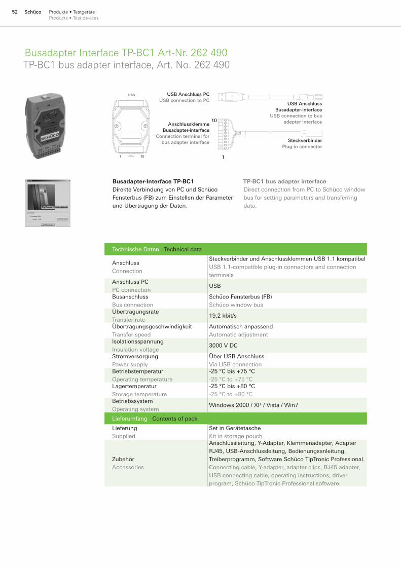
52 Schüco Produkte • TestgeräteProducts • Test devices
Busadapter Interface TP-BC1 Art-Nr. 262 490TP-BC1 bus adapter interface, Art. No. 262 490
Technische Daten Technical data
Anschluss Connection
Steckverbinder und Anschlussklemmen USB 1.1 kompatibelUSB 1.1-compatible plug-in connectors and connection terminals
Anschluss PC PC connection
USB
Busanschluss Bus connection
Schüco Fensterbus (FB) Schüco window bus
Übertragungsrate Transfer rate
19,2 kbit/s
Übertragungsgeschwindigkeit Transfer speed
Automatisch anpassend Automatic adjustment
Isolationsspannung Insulation voltage
3000 V DC
Stromversorgung Power supply
Über USB Anschluss Via USB connection
Betriebstemperatur Operating temperature
-25 °C bis +75 °C -25 °C to +75 °C
Lagertemperatur Storage temperature
-25 °C bis +80 °C -25 °C to +80 °C
Betriebssystem Operating system
Windows 2000 / XP / Vista / Win7
Lieferumfang Contents of pack
Lieferung Supplied
Set in Gerätetasche Kit in storage pouch
Zubehör Accessories
Anschlussleitung, Y-Adapter, Klemmenadapter, Adapter RJ45, USB-Anschlussleitung, Bedienungsanleitung, Treiberprogramm, Software Schüco TipTronic Professional.Connecting cable, Y-adapter, adapter clips, RJ45 adapter, USB connecting cable, operating instructions, driver program, Schüco TipTronic Professional software.
Busadapter-Interface TP-BC1Direkte Verbindung von PC und Schüco Fensterbus (FB) zum Einstellen der Parameter und Übertragung der Daten.
1
USB
1 10
USB Anschluss PCUSB connection to PC
Anschlussklemme Busadapter-interface
Connection terminal for bus adapter interface
USB Anschluss Busadapter-interface
USB connection to bus adapter interface
SteckverbinderPlug-in connector
10
TP-BC1 bus adapter interfaceDirect connection from PC to Schüco window bus for setting parameters and transferring data.
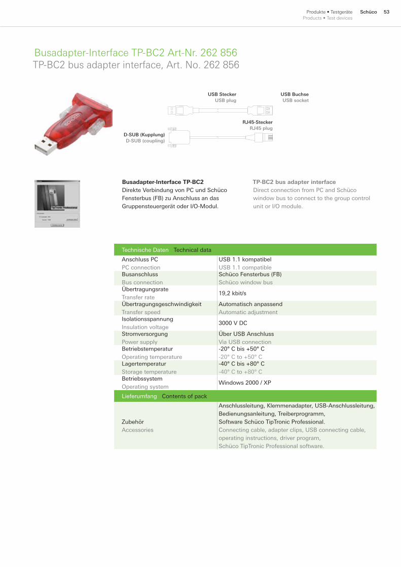
53SchücoProdukte • TestgeräteProducts • Test devices
Busadapter-Interface TP-BC2 Art-Nr. 262 856TP-BC2 bus adapter interface, Art. No. 262 856
Technische Daten Technical data
Anschluss PC PC connection
USB 1.1 kompatibel USB 1.1 compatible
Busanschluss Bus connection
Schüco Fensterbus (FB) Schüco window bus
Übertragungsrate Transfer rate
19,2 kbit/s
Übertragungsgeschwindigkeit Transfer speed
Automatisch anpassend Automatic adjustment
Isolationsspannung Insulation voltage
3000 V DC
Stromversorgung Power supply
Über USB Anschluss Via USB connection
Betriebstemperatur Operating temperature
-20° C bis +50° C -20° C to +50° C
Lagertemperatur Storage temperature
-40° C bis +80° C -40° C to +80° C
Betriebssystem Operating system
Windows 2000 / XP
Lieferumfang Contents of pack
Zubehör Accessories
Anschlussleitung, Klemmenadapter, USB-Anschlussleitung, Bedienungsanleitung, Treiberprogramm, Software Schüco TipTronic Professional.Connecting cable, adapter clips, USB connecting cable, operating instructions, driver program, Schüco TipTronic Professional software.
Busadapter-Interface TP-BC2Direkte Verbindung von PC und Schüco Fensterbus (FB) zu Anschluss an das Gruppensteuergerät oder I/O-Modul.
USB SteckerUSB plug
USB BuchseUSB socket
D-SUB (Kupplung)D-SUB (coupling)
RJ45-SteckerRJ45 plug
TP-BC2 bus adapter interfaceDirect connection from PC and Schüco window bus to connect to the group control unit or I/O module.
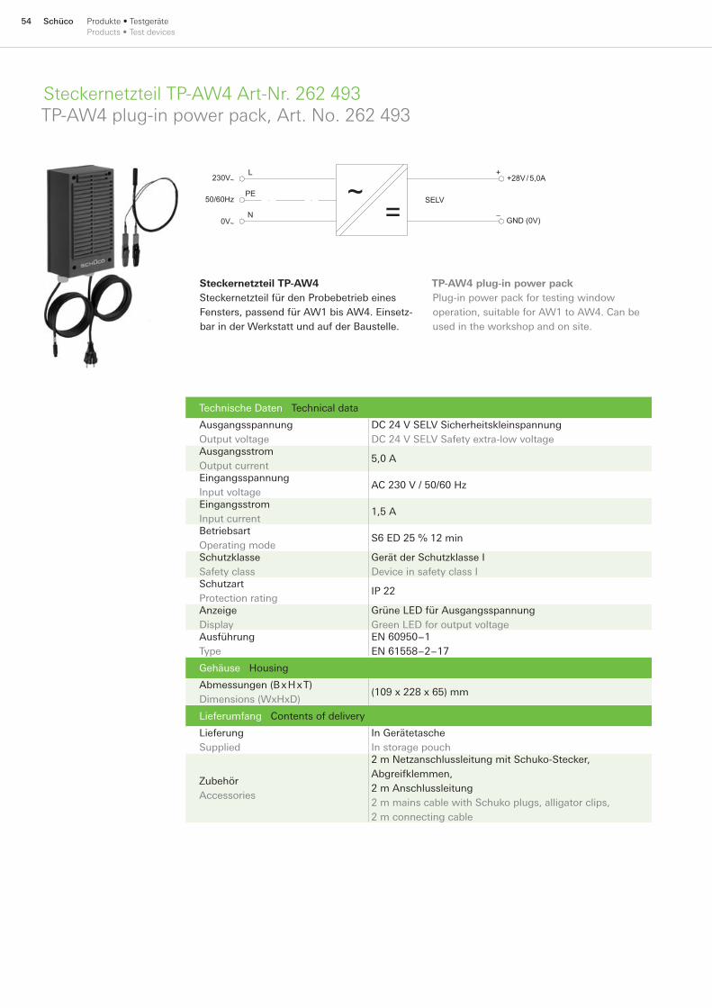
54 Schüco Produkte • TestgeräteProducts • Test devices
Steckernetzteil TP-AW4 Art-Nr. 262 493TP-AW4 plug-in power pack, Art. No. 262 493
Technische Daten Technical data
Ausgangsspannung Output voltage
DC 24 V SELV Sicherheitskleinspannung DC 24 V SELV Safety extra-low voltage
Ausgangsstrom Output current
5,0 A
Eingangsspannung Input voltage
AC 230 V / 50/60 Hz
Eingangsstrom Input current
1,5 A
Betriebsart Operating mode
S6 ED 25 % 12 min
Schutzklasse Safety class
Gerät der Schutzklasse I Device in safety class I
Schutzart Protection rating
IP 22
Anzeige Display
Grüne LED für Ausgangsspannung Green LED for output voltage
Ausführung Type
EN 60950−1 EN 61558−2−17
Gehäuse Housing
Abmessungen (B x H x T) Dimensions (WxHxD)
(109 x 228 x 65) mm
Lieferumfang Contents of delivery
Lieferung Supplied
In Gerätetasche In storage pouch
Zubehör Accessories
2 m Netzanschlussleitung mit Schuko-Stecker, Abgreifklemmen, 2 m Anschlussleitung2 m mains cable with Schuko plugs, alligator clips, 2 m connecting cable
~=
230V~
0V~
50/60Hz
+28V/ 5,0A
GND (0V)
SELV
L
PE
N
+
−
Steckernetzteil TP-AW4Steckernetzteil für den Probebetrieb eines Fensters, passend für AW1 bis AW4. Einsetz-bar in der Werkstatt und auf der Baustelle.
TP-AW4 plug-in power packPlug-in power pack for testing window operation, suitable for AW1 to AW4. Can be used in the workshop and on site.

55SchücoProdukte • TestgeräteProducts • Test devices
Schüco TipTronic Professional TP-SW1Schüco TipTronic Professional TP-SW1
Software Schüco TipTronic Professional TP-SW1Zum Betrieb der Busadapter-Interfaces TP-BC mit dem PC wird die Software Schüco TipTronic Professional benötigt. Mit diesem Programm können folgende Einstellungen und Diagnosefunktionen an den Fenstern durchgeführt werden:
Anpassen der Fahrpause für Powermanage-mentKontrollieren und Ändern der FensteradressenWechseln der BetriebsartAnsteuern der einzelnen Motoren im InbetriebnahmemodusAnpassen der maximalen Ausstellweite der KetteAktivieren bzw. Deaktivieren der Drehsperre bei DK-FensternDeaktivieren der automatischen Verriege-lung aus Drehstellung (Balkontürfunktion)Anpassen der Helligkeit der LED im e-GriffAnzeigen des Fensterstatus und Schaltleis-tenzustandsFernbedienen des Fensters für FunktionstestAuflisten der Ereignisse für FerndiagnoseAnzeige der durchgeführten Kipp- und DrehzyklenErstellen einer Protokolldatei für die DokumentationAnpassen der PWM-EinstellungenKonfigurieren der Eingänge X15 und X16 des GruppensteuergerätesAdressierung der Fenster (Notadressierung)
■
■■■
■
■
■
■■
■■■
■
■■
■
www.schueco.com
TP-SW1 Schüco TipTronic Professional softwareThe Schüco TipTronic Professional software is required to operate the TP-BC bus adapter interface using a PC. This program can be used to implement the following settings and diagnostic functions on the windows:
Adjust the break in travel for power managementCheck and change the window addressesChange the operating modeControl the individual motors in commissioning modeAdjust to the maximum length of the chainActivate and deactivate the anti-turn lock on turn/tilt windowsDeactivate the automatic locking from the turn position (balcony door function)Adjust the brightness of the LED in the e-handle
■
■■■
■■
■
■
Display the window status and status of the sensor stripRemotely operate the window for function testingList the results of the remote diagnosisDisplay the tilt and turn cycles carried outCreate a log file for the documentationAdjust the PWM settingsConfigure the X15 and X16 inputs of the group control unitSet the address of windows (emergency addressing)
■
■
■■■■■
■

56 Schüco Regeln und StrukturenRules and structures
Regeln und StrukturenRules and structures

57SchücoRegeln und StrukturenRules and structures
Planungshilfe für die bauseitige Ausführung des Schüco TipTronic Fensterbusses.
Design aid for on-site design of the Schüco TipTronic window bus.
PlanungshilfePlanning aid 58
58 Schüco Regeln und StrukturenRules and structures
Regel zur bauseitigen Installation des Schüco TipTronic FensterbussesRules for installing the Schüco TipTronic window Bus in the building
Regel Nr. 1Der GND (0 V) vom Fensterbus RS485 muss mit dem GND-Anschluss (0 V) des Schüco TipTronic Netzteils an einer definierten Stelle verbunden werden. Mehrere Verbindungsstel-len sind nicht zulässig. Werden Reiheneinbau-geräte für die Hutschiene verwendet, so erfolgt die Verbindung direkt im Schaltschrank.
Regel Nr. 2Sind mehrere Schüco TipTronic Netzteile innerhalb einer Fenstergruppe angeschlossen, so müssen alle GND-Anschlüsse (0 V) mit dem GND-Anschluss (0 V) vom Fensterbus RS485 verbunden werden. (vgl. Anwendungsbeispiel auf Seite 101)
Regel Nr. 3Die GND-Anschlüsse (0 V) aller Netzteile müssen so untereinander verbunden sein, dass sich keine Masseschleifen bilden können. Jedes Netzteil darf nur an einer Stelle mit dem GND-Potenzial (0 V) des Schüco Fensterbus RS485 verbunden werden.
Regel Nr. 4Der Schüco Fensterbus RS485 muss am Anfang und am Ende der Fensterbus-Hauptli-nie mit den mitgelieferten Busanschluss Widerständen (120 Ohm) versehen werden. Bei einer linienförmigen Busstruktur erfolgt dies in der Regel am Gruppensteuergerät und auf der Fensterseite in der letzten Abzweigdose, in der die Schüco TipTronic Rundleitung angeschlos-sen ist. (vgl. Beispiel A auf Seite 61)
Regel Nr. 5Als Busleitung für den Schüco Fensterbus kann die Steuerleitung J-Y(ST)Y 2 x 2 x 0,8 mm verwendet werden. Die maximale Gesamtlänge von Haupt- und Stichleitungen darf 300 m nicht überschreiten.
Regel Nr. 6Die Länge der einzelnen Stichleitungen zu den Schüco TipTronic Fenstern beträgt maximal 6 m. In Ausnahmefällen sind auch maximal 10 m zulässig, wenn Regel Nr. 5 beachtet wird.
Regel Nr. 7Der Schirm der Busleitung J-Y(ST)Y 2 x 2 x 0,8 mm braucht nicht angeschlossen werden.
Regel Nr. 8Sollten sich trotzdem auf der Busleitung Störungen einkoppeln, so kann der Schirm bzw. Erdungsbeidraht einseitig mit dem GND Potenzial (0 V) in der Abzweigdose verbunden werden.
Regel Nr. 9Der Schirm der Busleitung darf auf keinen Fall beidseitig angeschlossen bzw. aufgelegt werden.
Regel Nr. 10Der Schirm der Busleitung darf auf keinen Fall an den Schutzleiter PE; PEN oder an die Potenzialausgleichsschiene angeschlossen werden.
Rule No. 1The GND (0 V) of the RS485 window bus must be connected to the GND connection (0 V) on the Schüco TipTronic power pack in a specific position. Several different connection points are not admissible. If installation devices are used for the top hat rail, the connection will be made directly in the control cabinet.
Rule No. 2If there are several Schüco TipTronic power packs connected within one window group, all the GND connections (0 V) must be connected to the GND connection (0 V) of the RS485 window bus. (See example on page 101)
Rule No. 3The GND connections (0 V) of all power packs must be connected to one another in such a way that no mass loop can be formed. Each power pack can only be connected at one point with the GND potential (0 V) of the Schüco RS 485 window bus.
Rule No. 4The bus connection resistors (120 ohm) included in the pack must be fitted to the start and end of the main communication line of the Schüco RS485 window bus. If the bus structure is linear, this is generally done at the group control unit and on the window side, in the last junction box to which the Schüco TipTronic round cable is connected. (See example A on page 61)
Rule No. 5Control cable J-Y(ST)Y 2 x 2 x 0.8 mm can be used as the bus cable for the Schüco window bus. The overall length of the main and spur cables must not exceed 300 m.
Rule No. 6The length of the individual spur cables to the Schüco TipTronic windows can be a maximum of 6 m. In exceptional cases 10 m is also an option if Rule 5 is adhered to.
Rule No. 7The shield of the J-Y(ST)Y 2 x 2 x 0.8 mm bus cable does not need to be connected.
Rule No. 8If interference should link into the bus cable, the shield and earth wire can be connected on one side to the GND potential (0 V) in the junction box.
Rule No. 9Under no circumstances must the bus cable shield be connected / attached on both sides.
Rule No. 10Under no circumstances must the bus cable be attached to the protective earth conductor PE, PEN, or to the potential compensation rail.
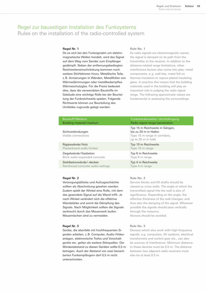
59SchücoRegeln und StrukturenRules and structures
Regel zur bauseitigen Installation des FunksystemsRules on the installation of the radio-controlled system
Regel Nr. 1Da es sich bei den Funksignalen um elektro-magnetische Wellen handelt, wird das Signal auf dem Weg vom Sender zum Empfänger gedämpft. Neben der entfernungsbedingten Reichweiteneinschränkung kommen noch weitere Störfaktoren hinzu: Metallische Teile, z. B. Armierungen in Wänden, Metallfolien von Wärmedämmungen oder metallbedampftes Wärmeschutzglas. Für die Praxis bedeutet dies, dass die verwendeten Baustoffe im Gebäude eine wichtige Rolle bei der Beurtei-lung der Funkreichweite spielen. Folgende Richtwerte können zur Beurteilung des Umfeldes zugrunde gelegt werden:
Baustoff / Medium Building material / medium
Funkstreckenweite / -durchdringung Radio signal range / penetration
Sichtverbindungen Visible connections
Typ 15 m Reichweite in Gängen, bis zu 20 m in Hallen Type 15 m range in corridors, up to 20 m in halls
Rigipswände / Holz Plasterboard walls / timber
Typ 10 m Reichweite Type 10 m range
Ziegelwände / Gasbeton Brick walls / expanded concrete
Typ 6 m Reichweite Type 6 m range
Stahlbetonwände / -decken Reinforced concrete walls / ceilings
Typ 4 m Reichweite Type 4 m range
Rule No. 1As radio signals are electromagnetic waves, the signal is damped on its path from the transmitter to the receiver. In addition to the distance-related range limitations, other interference factors also come into play: metal components, e. g. wall ties, metal foil on thermal insulation or vapour-plated insulating glass. In practice this means that the building materials used in the building will play an important role in judging the radio signal range. The following approximate values are fundamental in assessing the surroundings:
Regel Nr. 2Versorgungsblöcke und Aufzugsschächte sollten als Abschottung gesehen werden. Zudem spielt der Winkel eine Rolle, mit dem das gesendete Signal auf die Wand trifft. Je nach Winkel verändert sich die effektive Wandstärke und somit die Dämpfung des Signals. Nach Möglichkeit sollten die Signale senkrecht durch das Mauerwerk laufen. Mauernischen sind zu vermeiden.
Rule No. 2Service blocks and lift shafts should be viewed as cross walls. The angle at which the transmitted signal hits the wall is also of significance. Depending on the angle, the effective thickness of the wall changes, and thus also the damping of the signal. Wherever possible the signals should pass vertically through the masonry. Alcoves should be avoided.
Regel Nr. 3Geräte, die ebenfalls mit hochfrequenten Si-gnalen arbeiten, z. B. Computer, Audio-/Video-anlagen, elektronische Trafos und Vorschalt-geräte etc. gelten als weitere Störquellen. Der Mindestabstand zu diesen Geräten sollte 0,5 m betragen. Auch der Abstand von zwei benach- barten Funkempfängern darf 0,5 m nicht unterschreiten.
Rule No. 3Devices which also work with high-frequency signals, e.g. computers, AV systems, electrical transformers and control gear etc., can also be sources of interference. Minimum distance to these devices must be 0.5 m. The distance between two adjacent radio receivers must also be at least 0.5 m.
60 Schüco Regeln und StrukturenRules and structures
Regel zur bauseitigen Installation des FunksystemsRules on the installation of the radio-controlled system
Regel Nr. 4Bei Pfosten-Riegel-Kombinationen kann die Reichweite des Funkgriffs zu Oberlichtern durch die Abschottung des Signalweges erheblich eingeschränkt sein. Hier wird der Einsatz des Schüco Repeaters (Art.-Nr. 262 839) empfohlen.
Regel Nr. 5Pro Empfänger können max. 200 Sender (Fernbedienungen oder Funkgriffe) gespei-chert werden. Ein Empfänger kann nur einmal pro Sender (Fernbedienungen, Funkgriffe, Transponder, Funkschalter) eingelernt werden, d. h. ein Empfänger kann nicht gleichzeitig auf Kanal 1 und 2 des selben Senders eingelernt werden. Maximale Reichweite von 20 m (Frei-feld) kann im Gebäude deutlich verringert sein.
Rule No. 4With mullion and transom combinations, the range of the radio-controlled handle to the toplights can be significantly reduced by closing off the path of the signal. In this case, the use of the Schüco repeater (Art. No. 262 839) is recommended.
Rule No. 5A maximum of 200 transmitters (remote controls or radio-controlled handles) can be stored on each receiver. A receiver can only be registered once per transmitter (remote controls, radio-controlled handles, transponders, radio-controlled switches), i. e. a receiver cannot be registered on channel 1 and 2 of the same transmitter. Maximum range of 20 m (free-field) can be significantly reduced in the building.
Beispiel A Example A
GC
Abschlusswiderstand (120 Ohm)Terminator (120 Ohm)
Stichleitung max. 6 mSpur cable max. 6 m
Fensterbus HauptlinieWindow bus main communication line
UnterverteilungHousing
max. Leitungslänge = 300 mMax. cable length = 300 m
AbzweigdoseConduit box
Schüco TipTronic max. 30
2 x 2 x 0,8 mm
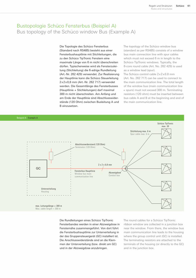
61SchücoRegeln und StrukturenRules and structures
Bustopologie Schüco Fensterbus (Beispiel A)Bus topology of the Schüco window Bus (Example A)
Die Rundleitungen eines Schüco TipTronic Fensterbandes werden in einer Abzweigdose in Fensternähe zusammengeführt. Von dort führt die Fensterbushauptlinie zur Unterverteilung in der das Gruppensteuergerät (GC) installiert ist. Die Anschlusswiderstände sind an die Klem-men der Unterverteilung (bzw. direkt am GC) und in der Abzweigdose anzubringen.
The round cables for a Schüco TipTronic ribbon window are collected in a junction box near the window. From there, the window bus main communication line leads to the housing where the group control unit (GC) is installed. The terminating resistors are attached to the terminals of the housing (or directly to the GC) and in the junction box.
Die Topologie des Schüco Fensterbus (Standard nach RS485) besteht aus einer Fensterbushauptlinie mit Stichleitungen, die zu den Schüco TipTronic Fenstern eine maximale Länge von 6 m nicht überschreiten dürfen. Typischerweise wird als Fensterzulei-tung (Stichleitung) die 6-adrige Rundleitung (Art.-Nr. 262 429) verwendet. Zur Realisierung der Hauptlinie kann die Schüco Steuerleitung 2 x 2 x 0,8 mm (Art.-Nr. 262 717) verwendet werden. Die Gesamtlänge des Fensterbusses (Hauptlinie + Stichleitungen) darf maximal 300 m nicht überschreiten. Am Anfang und am Ende der Hauptlinie sind Abschlusswider-stände (120 Ohm) zwischen Busleitung A und B einzusetzen.
The topology of the Schüco window bus (standard as per RS485) consists of a window bus main connection line with spur cables which must not exceed 6 m in length to the Schüco TipTronic windows. Typically, the 6-core round cable (Art. No. 262 429) is used as a window lead (spur). The Schüco control cable 2 x 2 x 0.8 mm (Art. No. 262 717) can be used to connect to the main communication line. The total length of the window bus (main communication line + spurs) must not exceed 300 m. Terminating resistors (120 ohm) must be inserted between bus cable A and B at the beginning and end of the main communication line.
Beispiel A Example A
GC
Abschlusswiderstand (120 Ohm)Terminator (120 Ohm)
Stichleitung max. 6 mSpur cable max. 6 m
Fensterbus HauptlinieWindow bus main communication line
UnterverteilungHousing
max. Leitungslänge = 300 mMax. cable length = 300 m
AbzweigdoseConduit box
Schüco TipTronic max. 30
2 x 2 x 0,8 mm
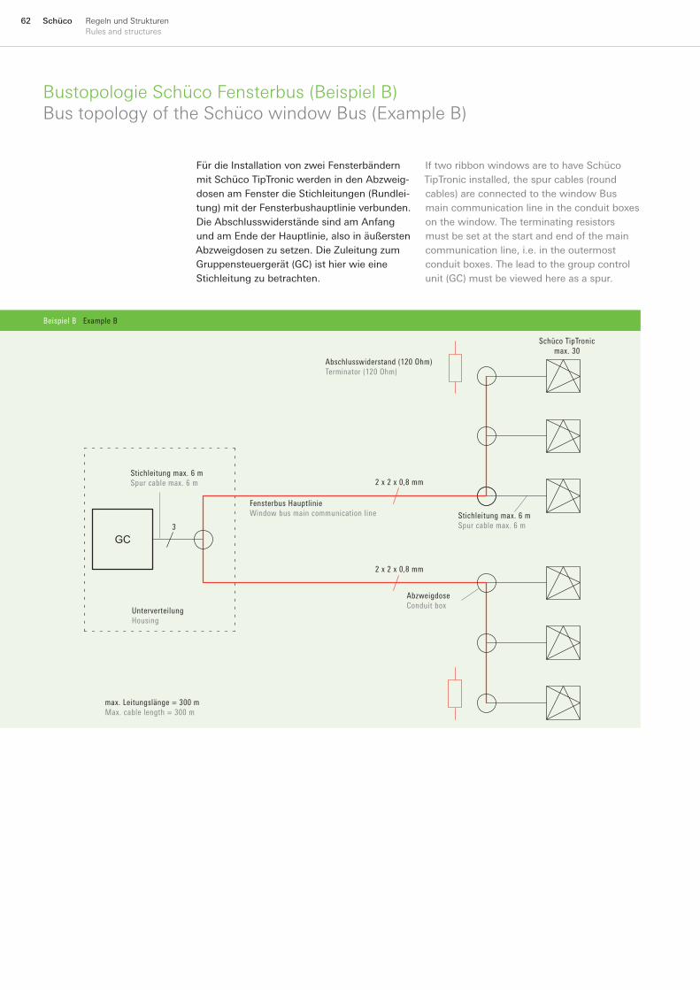
62 Schüco Regeln und StrukturenRules and structures
Bustopologie Schüco Fensterbus (Beispiel B)Bus topology of the Schüco window Bus (Example B)
Für die Installation von zwei Fensterbändern mit Schüco TipTronic werden in den Abzweig-dosen am Fenster die Stichleitungen (Rundlei-tung) mit der Fensterbushauptlinie verbunden. Die Abschlusswiderstände sind am Anfang und am Ende der Hauptlinie, also in äußersten Abzweigdosen zu setzen. Die Zuleitung zum Gruppensteuergerät (GC) ist hier wie eine Stichleitung zu betrachten.
If two ribbon windows are to have Schüco TipTronic installed, the spur cables (round cables) are connected to the window Bus main communication line in the conduit boxes on the window. The terminating resistors must be set at the start and end of the main communication line, i.e. in the outermost conduit boxes. The lead to the group control unit (GC) must be viewed here as a spur.
Beispiel B Example B
GC
Abschlusswiderstand (120 Ohm)Terminator (120 Ohm)
Stichleitung max. 6 mSpur cable max. 6 m
Fensterbus HauptlinieWindow bus main communication line
UnterverteilungHousing
max. Leitungslänge = 300 mMax. cable length = 300 m
AbzweigdoseConduit box
Schüco TipTronic max. 30
2 x 2 x 0,8 mm
2 x 2 x 0,8 mm
Stichleitung max. 6 mSpur cable max. 6 m 3
Beispiel C Example C
GC
Abschlusswiderstand (120 Ohm)Terminating resistor (120 ohm)
Stichleitung max. 6 mSpur cable max. 6 m
Fensterbus HauptlinieWindow bus main communication line
Schüco TipTronic max. 30
2 x 2 x 0,8 mm

63SchücoRegeln und StrukturenRules and structures
Bustopologie Schüco Fensterbus (Beispiel C)Bus topology of the Schüco window Bus (Example C)
Die Rundleitungen der Schüco TipTronic Fenster werden direkt in eine Unterverteilung in Fensternähe geführt. Ein Abschlusswider-stand ist direkt an den Klemmen des Gruppen-steuergerätes (GC) zu setzen, der andere an der Klemmenleiste. Die Verbindungsleitung von Gruppensteuergerät und Klemmenleiste bildet nun die Hauptleitung.
The round cables for the Schüco TipTronic windows are fed directly into a housing near the window. One terminating resistor must be set directly on the terminals of the group control unit (GC), the other on the terminal block. The connecting cable of the group control unit and terminal block now form the main communication line.
Beispiel C Example C
GC
Abschlusswiderstand (120 Ohm)Terminating resistor (120 ohm)
Stichleitung max. 6 mSpur cable max. 6 m
Fensterbus HauptlinieWindow bus main communication line
Schüco TipTronic max. 30
2 x 2 x 0,8 mm
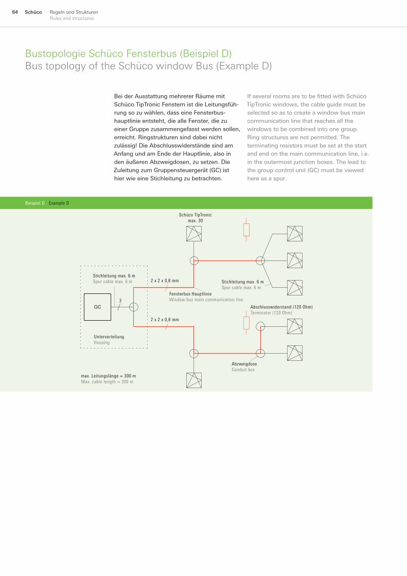
64 Schüco Regeln und StrukturenRules and structures
Bustopologie Schüco Fensterbus (Beispiel D)Bus topology of the Schüco window Bus (Example D)
Bei der Ausstattung mehrerer Räume mit Schüco TipTronic Fenstern ist die Leitungsfüh-rung so zu wählen, dass eine Fensterbus-hauptlinie entsteht, die alle Fenster, die zu einer Gruppe zusammengefasst werden sollen, erreicht. Ringstrukturen sind dabei nicht zulässig! Die Abschlusswiderstände sind am Anfang und am Ende der Hauptlinie, also in den äußeren Abzweigdosen, zu setzen. Die Zuleitung zum Gruppensteuergerät (GC) ist hier wie eine Stichleitung zu betrachten.
If several rooms are to be fitted with Schüco TipTronic windows, the cable guide must be selected so as to create a window bus main communication line that reaches all the windows to be combined into one group. Ring structures are not permitted. The terminating resistors must be set at the start and end on the main communication line, i.e. in the outermost junction boxes. The lead to the group control unit (GC) must be viewed here as a spur.
Beispiel D Example D
GC
Schüco TipTronic max. 30
Abschlusswiderstand (120 Ohm)Terminator (120 Ohm)
Stichleitung max. 6 mSpur cable max. 6 m
Fensterbus HauptlinieWindow bus main communication line
UnterverteilungHousing
max. Leitungslänge = 300 mMax. cable length = 300 m
AbzweigdoseConduit box
2 x 2 x 0,8 mm
2 x 2 x 0,8 mm Stichleitung max. 6 mSpur cable max. 6 m
3
Beispiel E Example E
3
(A)
(B)
(C)
max. 10 m
max. 15 m
max. 4 m
max
. 4 m

65SchücoRegeln und StrukturenRules and structures
Bustopologie Schüco Funkstruktur (Beispiel E)Bus topology of the Schüco radio-control structure (example E)
Mehrere Räume sind mit Schüco TipTronic Oberlichtern und Schüco AvanTec Dreh-Kipp-Fenstern mit Funkgriff ausgestattet. Die Reichweite der Handsender max. 10 m (A) ist deutlich größer, als die Reichweite der Funkgriffe (max. 4 m). Bei Reichweiten-Einschränkungen durch ausladende Pfosten-Riegel-Konstruktionen (B) max. 4 m kann durch einen Repeater (Art.-Nr. 262 839) wie (C) max. 15 m, eine Verbesserung erzielt werden.
Several rooms are fitted with Schüco TipTronic toplights and Schüco AvanTec turn / tilt windows with radio-controlled handles. At 10 m (A), the maximum range of the manual transmitters is significantly greater than the range of the radio-controlled handle (max. 4 m). The restricted range due to projecting mullion / transom constructions (B) max. 4 m can be improved by using a repeater (Art. No. 262 839) such as (C) max. 15 m.
Beispiel E Example E
3
(A)
(B)
(C)
max. 10 m
max. 15 m
max. 4 m
max
. 4 m

66 Schüco Regeln und StrukturenRules and structures
Bustopologie Schüco ControlPanel und Schüco TipTronic (Beispiel F)Bus topology of the Schüco ControlPanel and Schüco TipTronic (example F)
An die RS485 Schnittstelle des Schüco ControlPanels kann maximal ein Schüco TipTronic Gruppensteuergerät angeschlossen werden.
A maximum of one Schüco TipTronic group control unit can be connected to the RS485 interface of the Schüco ControlPanel.
Beispiel F Example F
Ethernet
TCP/IP
1 2 3 30
Einbindung an RS485 Kommunikationsbus Anbindung einer Schüco TipTronic FenstergruppeConnection into RS485 communication bus Connection of one Schüco TipTronic window group
Schüco ControlPanelSchüco ControlPanel
Schüco TipTronic GruppensteuergerätSchüco TipTronic Group control unit
Schüco TipTronic FensterSchüco TipTronic window
Schüco FensterbusSchüco window Bus
Beispiel G Example G
Ethernet
TCP/IP
1 30 1 30
Einbindung an RS485 Kommunikationsbus Anbindung mehrerer Schüco TipTronic FenstergruppenConnection into RS485 communication bus Connection of several Schüco TipTronic window groups
Buskoppler Ethernet RS485Bus coupler Ethernet RS485
Schüco ControlPanelSchüco ControlPanel
Schüco TipTronic GruppensteuergerätSchüco TipTronic Group control unit
Schüco TipTronic FensterSchüco TipTronic window
Schüco FensterbusSchüco window Bus
Schüco TipTronic GruppensteuergerätSchüco TipTronic Group control unit
Schüco TipTronic FensterSchüco TipTronic window
Schüco FensterbusSchüco window Bus

67SchücoRegeln und StrukturenRules and structures
Bustopologie Schüco ControlPanel und Schüco TipTronic (Beispiel G)Bus topology of the Schüco ControlPanel and Schüco TipTronic (example G)
Beispiel G Example G
Ethernet
TCP/IP
1 30 1 30
Einbindung an RS485 Kommunikationsbus Anbindung mehrerer Schüco TipTronic FenstergruppenConnection into RS485 communication bus Connection of several Schüco TipTronic window groups
Buskoppler Ethernet RS485Bus coupler Ethernet RS485
Schüco ControlPanelSchüco ControlPanel
Schüco TipTronic GruppensteuergerätSchüco TipTronic Group control unit
Schüco TipTronic FensterSchüco TipTronic window
Schüco FensterbusSchüco window Bus
Schüco TipTronic GruppensteuergerätSchüco TipTronic Group control unit
Schüco TipTronic FensterSchüco TipTronic window
Schüco FensterbusSchüco window Bus
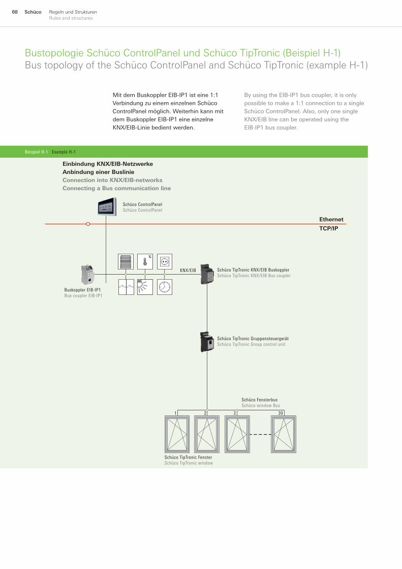
68 Schüco Regeln und StrukturenRules and structures
Bustopologie Schüco ControlPanel und Schüco TipTronic (Beispiel H-1)Bus topology of the Schüco ControlPanel and Schüco TipTronic (example H-1)
Mit dem Buskoppler EIB-IP1 ist eine 1:1 Verbindung zu einem einzelnen Schüco ControlPanel möglich. Weiterhin kann mit dem Buskoppler EIB-IP1 eine einzelne KNX/EIB-Linie bedient werden.
By using the EIB-IP1 bus coupler, it is only possible to make a 1:1 connection to a single Schüco ControlPanel. Also, only one single KNX/EIB line can be operated using the EIB-IP1 bus coupler.
Beispiel H-1 Example H-1
1 2 3 30
Ethernet
TCP/IP
KNX/EIB
Schüco ControlPanelSchüco ControlPanel
Einbindung KNX/EIB-Netzwerke Anbindung einer BuslinieConnection into KNX/EIB-networks Connecting a Bus communication line
Buskoppler EIB-IP1Bua coupler EIB-IP1
Schüco TipTronic KNX/EIB BuskopplerSchüco TipTronic KNX/EIB Bus coupler
Schüco TipTronic GruppensteuergerätSchüco TipTronic Group control unit
Schüco TipTronic FensterSchüco TipTronic window
Schüco FensterbusSchüco window Bus
Beispiel H-2 Example H-2
1 2 3 30
Ethernet
TCP/IP
KN
X/E
IB
Einbindung KNX/ EIB-Netzwerke Anbindung mehrerer BuslinienConnection into KNX/EIB-networks Connecting several Bus communication lines
Schüco ControlPanelSchüco ControlPanel
Schüco TipTronic KNX/EIB BuskopplerSchüco TipTronic KNX/EIB Bus coupler
Buskoppler EIB-IP2Bua coupler EIB-IP2
Schüco TipTronic GruppensteuergerätSchüco TipTronic Group control unit
Schüco TipTronic FensterSchüco TipTronic window
Schüco FensterbusSchüco window Bus
Auf den Buskoppler EIB-IP2 können auch mehrere Schüco ControlPanels zugreifenSeveral Schüco ControlPanels can also access the EIB-IP2 bus coupler
Linie 1Line 1
Linie 2Line 2
Linie 3Line 3
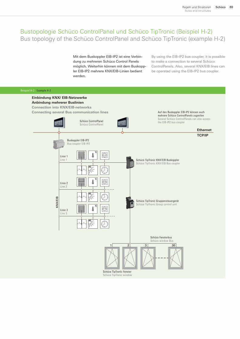
69SchücoRegeln und StrukturenRules and structures
Bustopologie Schüco ControlPanel und Schüco TipTronic (Beispiel H-2)Bus topology of the Schüco ControlPanel and Schüco TipTronic (example H-2)
Mit dem Buskoppler EIB-IP2 ist eine Verbin-dung zu mehreren Schüco Control Panels möglich. Weiterhin können mit dem Buskopp-ler EIB-IP2 mehrere KNX/EIB-Linien bedient werden.
By using the EIB-IP2 bus coupler, it is possible to make a connection to several Schüco ControlPanels. Also, several KNX/EIB lines can be operated using the EIB-IP2 bus coupler.
Beispiel H-2 Example H-2
1 2 3 30
Ethernet
TCP/IP
KN
X/E
IB
Einbindung KNX/ EIB-Netzwerke Anbindung mehrerer BuslinienConnection into KNX/EIB-networks Connecting several Bus communication lines
Schüco ControlPanelSchüco ControlPanel
Schüco TipTronic KNX/EIB BuskopplerSchüco TipTronic KNX/EIB Bus coupler
Buskoppler EIB-IP2Bua coupler EIB-IP2
Schüco TipTronic GruppensteuergerätSchüco TipTronic Group control unit
Schüco TipTronic FensterSchüco TipTronic window
Schüco FensterbusSchüco window Bus
Auf den Buskoppler EIB-IP2 können auch mehrere Schüco ControlPanels zugreifenSeveral Schüco ControlPanels can also access the EIB-IP2 bus coupler
Linie 1Line 1
Linie 2Line 2
Linie 3Line 3
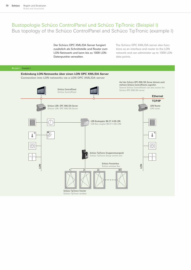
70 Schüco Regeln und StrukturenRules and structures
Bustopologie Schüco ControlPanel und Schüco TipTronic (Beispiel I)Bus topology of the Schüco ControlPanel and Schüco TipTronic (example I)
The Schüco OPC XML/DA server also func-tions as an interface and router to the LON network and can administer up to 1000 LON data points.
Der Schüco OPC XML/DA Server fungiert zusätzlich als Schnittstelle und Router zum LON-Netzwerk und kann bis zu 1000 LON-Datenpunkte verwalten.
Beispiel I Example I
Ethernet
TCP/IP
1 2 3 30
LON
LON
Schüco TipTronic GruppensteuergerätSchüco TipTronic Group control unit
Einbindung LON-Netzwerke über einen LON OPC XML/DA ServerConnection into LON networks via a LON OPC XML/DA server
Schüco ControlPanelSchüco ControlPanel
LON RouterLON router
Auf den Schüco OPC-XML/DA Server können auch mehrere Schüco ControlPanels zugreifenSeveral Schüco ControlPanels can also access the Schüco OPC-XML/DA server
Schüco TipTronic FensterSchüco TipTronic window
Schüco FensterbusSchüco window Bus
LON Buskoppler BK-ET 4-KB-LONLON Bus coupler BK-ET 4-KB-LON
Schüco LON: OPC XML/DA ServerSchüco LON: OPC XML/DA Server

71SchücoRegeln und StrukturenRules and structures

72 Schüco AnwendungsbeispieleExamples
AnwendungsbeispieleExamples
73SchücoAnwendungsbeispieleExamples
74
78
84
86
88
90
102
112
SchücobietetIhnendieMöglichkeiteineroptimalenPlanungIhrerGebäude-automation
Schücoallowsyoutocreateanoptimumdesignforyourbuildingautomationsystem
EingängeA+BamGruppen-steuergerätGS-ET2A+BinputsontheGS-ET2groupcontrolunit
EinzelfensterSinglewindow
KonventionelleEinzel-undGruppensteuerungConventionalindividualandgroupcontrol
KNX/EIBGruppen-undZentralsteuerungKNX/EIBgroupandcentralcontrol
LONGruppen-undZentral-steuerungLONgroupandcentralcontrol
FunksteuerungRadiocontrol
FenstergruppenWindowgroups
AbkürzungenAbbreviations
~=
~=
~=
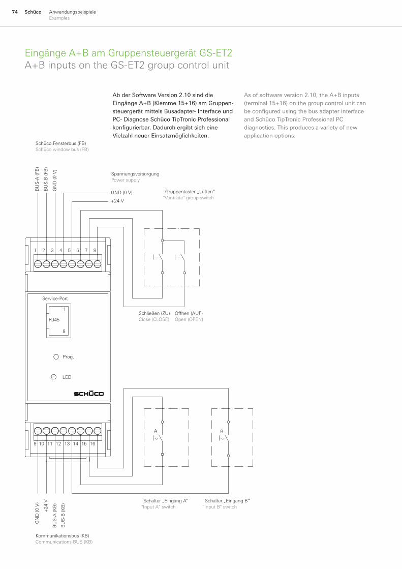
74 Schüco AnwendungsbeispieleExamples
+24
V
1
8
1 8
9 16
Service-Port
GND(0V)
GN
D(0
V)
+24V
BU
S-A
(FB
)
BU
S-B
(FB
)
BU
S-A
(KB
)
BU
S-B
(KB
)
GN
D(0
V)
BA
LED
RJ45
2 3 4 5 6 7
131210 11 14 15
EingängeA+BamGruppensteuergerätGS-ET2A+BinputsontheGS-ET2groupcontrolunit
Schließen(ZU)Close(CLOSE)
Öffnen(AUF)Open(OPEN)
Prog.
Kommunikationsbus(KB)CommunicationsBUS(KB)
SpannungsversorgungPowersupply
Gruppentaster„Lüften“"Ventilate"groupswitch
SchücoFensterbus(FB)Schücowindowbus(FB)
Schalter„EingangA“"InputA"switch
Schalter„EingangB“"InputB"switch
AbderSoftwareVersion2.10sinddieEingängeA+B(Klemme15+16)amGruppen-steuergerätmittelsBusadapter-InterfaceundPC-DiagnoseSchücoTipTronicProfessionalkonfigurierbar. Dadurch ergibt sich eine VielzahlneuerEinsatzmöglichkeiten.
Asofsoftwareversion2.10,theA+Binputs(terminal15+16)onthegroupcontrolunitcanbe configured using the bus adapter interface andSchücoTipTronicProfessionalPCdiagnostics.Thisproducesavarietyofnewapplicationoptions.
75SchücoAnwendungsbeispieleExamples
Lüftungssperre (Sicherheit)DieseFunktionwirdz.B.zumAnschlusseinesWind-undRegenmeldersgenutzt.BeistarkemWindoderbeiRegenschließendieFensterautomatisch.DiesistdieStandardbelegungvonEingangB(Schalterfunktion).
Drehsperre aufhebenDreh-Kipp-FenstermitDrehsperrekönnenzumDrehenfreigegebenwerden;Dreh-Kipp-FensterohneGriffwerdenunmittelbarinDrehstellunggeöffnet.DiesistdieStandard-belegungvonEingangA(Schalterfunktion).
Lüften 100 %DieFensteröffnenzumLüftenauf100%derÖffnungsweite(Schalterfunktion).
Spaltlüften 50 %DieFensteröffnenzumSpaltlüftenaufz.B.50%derÖffnungsweite.DieÖffnungsweiteistmittelsBusadapter-InterfaceundPC-DiagnoseSchücoTipTronicProfessionaleinstellbar(gemeinsameEinstellungfüralleFensterindieserGruppe)(Schalterfunktion).
ZeitlüftenDieFensteröffnenzumLüftenundschließenautomatischnachAblaufderLüftungsdauer(Tasterfunktion).
Natürliches LüftenDieFensteröffnenzumSpaltlüftenundschließenautomatischnachAblaufderLüftungsdauer.DieZeitistmittelsBusadapter-InterfaceundPC-DiagnoseSchücoTipTronicProfessionalvon10bis240Minuteneinstell-bar(gemeinsameEinstellungfüralleFensterindieserGruppe)(Tasterfunktion).
ZuluftstellungDieFensteröffneninZuluftstellungz.B.fürNachtauskühlungundkönnenüberdieLüftungssperre(Sicherheit)geschlossenwerdenz.B.miteinemWind-undRegenmel-der(Schalterfunktion).
EntriegelnAlleDreh-Kipp-FensterwerdenunmittelbarinDrehstellungentriegelt.FallsSienichtsofortinDrehstellunggebrachtwerden,verriegelnSieanschließendwieder(Tasterfunktion).
BediensperreDieFensterkönnennichtmehrdirektüberdenGriff,TasteroderFunkbedientwerden(Schalterfunktion).
StoppenDieFensterstoppensofort(Tasterfunktion).
Folgende Funktionen sind einstellbar:
Ventilation lock (security)Thisfunctionisusedfortheconnectionofawindandrainsensor.Thewindowscloseautomaticallyinstrongwindsorwhenitrains.This is the standard configuration for input B (maintainedcontactswitchfunction).
Override the anti-turn lockTurn/tiltwindowswithanti-turnlockcanbereleasedforturning;turn/tiltwindowswithoutahandleareimmediatelyopenedintheturnposition. This is the standard configuration for inputA(maintainedcontactswitchfunction).
100 % ventilationThewindowsopentotheirfullopeningwidthforventilation(maintainedcontactswitchfunction).
50 % night ventilationThewindowsopentoe.g.50%oftheiropeningwidthfornightventilation.TheopeningwidthcanbesetusingthebusadapterinterfaceandSchücoTipTronicProfessionalPCdiagnostics(samesettingforallwindowsinthisgroup)(maintainedcontactswitchfunction).
Timed ventilationThewindowsopenforventilationandcloseautomaticallyaftertheventilationperiodhaselapsed(momentarycontactswitchfunction).
Natural ventilationThewindowsopenfornightventilationandcloseautomaticallyaftertheventilationperiodhaselapsed.Thetimecanbesetfrom10to240minutesusingthebusadapterinterfaceandSchücoTipTronicProfessionalPCdiagnostics(samesettingforallwindowsinthisgroup)(momentarycontactswitchfunction).
Ventilation positionThewindowsopenintheventilationposition,e.g.fornight-timecooling,andcanbeclosedviatheventilationlock(security),e.g.usingawindandrainsensor(maintainedcontactswitchfunction).
UnlockAllturn/tiltwindowsareimmediatelyunlockedintheturnposition.Iftheydonotimmediatelyopenintheturnposition,theywillthenlockagain(momentarycontactswitchfunction).
Lock operationThewindowscannolongerbedirectlyoperatedviathehandle,momentarycontactswitchorradiocontrol(maintainedcontactswitchfunction).
StopThewindowsstopimmediately(momentarycontactswitchfunction).
Thefollowingfunctionscanbeset:
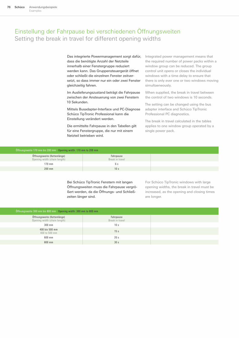
76 Schüco AnwendungsbeispieleExamples
EinstellungderFahrpausebeiverschiedenenÖffnungsweitenSettingthebreakintravelfordifferentopeningwidths
Öffnungsweite 170 mm bis 200 mm Opening width: 170 mm to 200 mm
Öffnungsweite (Kettenlänge)Opening width (chain length)
FahrpauseBreak in travel
170 mm 6 s
200 mm 10 s
DasintegriertePowermanagementsorgtdafür,dassdiebenötigteAnzahlderNetzteileinnerhalbeinerFenstergruppereduziertwerdenkann.DasGruppensteuergerätöffnetoderschließtdieeinzelnenFensterzeitver-setzt,sodassimmernureinoderzweiFenstergleichzeitigfahren.
ImAuslieferungszustandbeträgtdieFahrpausezwischenderAnsteuerungvonzweiFenstern10Sekunden.
MittelsBusadapter-InterfaceundPC-DiagnoseSchücoTipTronicProfessionalkanndieEinstellungverändertwerden.
DieermittelteFahrpauseindenTabellengiltfüreineFenstergruppe,dienurmiteinemNetzteilbetriebenwird.
Integratedpowermanagementmeansthattherequirednumberofpowerpackswithinawindowgroupcanbereduced.Thegroupcontrolunitopensorclosestheindividualwindowswithatimedelaytoensurethatthereisonlyeveroneortwowindowsmovingsimultaeneously.
Whensupplied,thebreakintravelbetweenthecontroloftwowindowsis10seconds.
ThesettingcanbechangedusingthebusadapterinterfaceandSchücoTipTronicProfessionalPCdiagnostics.
Thebreakintravelcalculatedinthetablesappliestoonewindowgroupoperatedbyasinglepowerpack.
Öffnungsweite 300 mm bis 800 mm Opening width: 300 mm to 800 mm
Öffnungsweite (Kettenlänge)Opening width (chain length)
FahrpauseBreak in travel
300 mm 10 s
400 bis 500 mm400 to 500 mm
15 s
600 mm 20 s
800 mm 30 s
BeiSchücoTipTronicFensternmitlangenÖffnungsweitenmussdieFahrpausevergrö-ßertwerden,dadieÖffnungs-undSchließ-zeitenlängersind.
ForSchücoTipTronicwindowswithlargeopeningwidths,thebreakintravelmustbeincreased,astheopeningandclosingtimesarelonger.
Öffnungsweite 170 mm bis 200 mm (ohne Griff) Opening width: 170 mm to 200 mm (without handle)
Max. Anzahl der Fenster pro NetzteilMax. number of windows per power pack
Netzteil AW2Power pack AW2
Netzteil AW4Power pack AW4
FahrpauseBreak in travel
Fenster Window
Fenster Window
AW1 AW2 AW3 AW4 AW1 AW2 AW3 AW4
0 s 3 1 - - 6 4 3 2
3 s 30 1 - - 30 30 30 30
10 s 30 30 - - 30 30 30 30
Öffnungsweite 170 mm bis 200 mm (mit Griff, Bedienwippe, Taster oder Funkempfänger) Opening width: 170 mm to 200 mm (with handle, rocker switch, momentary contact switch or radio receiver)
Max. Anzahl der Fenster pro NetzteilMax. number of windows per power pack
Netzteil AW2Power pack AW2
Netzteil AW4Power pack AW4
Fahrpause Break in travel
Fenster Window
Fenster Window
AW1 AW2 AW3 AW4 AW1 AW2 AW3 AW4
0 s 3 1 - - 6 4 3 2
3 s 5 1 - - 10 6 4 3
10 s 5 2 - - 10 6 4 3
Öffnungsweite 300 mm (ohne Funkempfänger) Opening width: 300 mm (without radio receiver)
Max. Anzahl der Fenster pro NetzteilMax. number of windows per power pack
Netzteil AW2Power pack AW2
Netzteil AW4Power pack AW4
Fahrpause Break in travel
Fenster Window
Fenster Window
AW1 AW2 AW3 AW4 AW1 AW2 AW3 AW4
0 s - 1 - - - 2 - 1
4 s - 2 - - - 30 - 2
10 s - 30 - - - 30 - 30

77SchücoAnwendungsbeispieleExamples
NetzteildimensionierungbeiverkürztenFahrpausenPowerpackdimensioningforshortenedbreaksintravel
SolldieFahrpauseverkürztwerden,somussdieAnzahlderNetzteileinnerhalbderFenstergruppeerhöhtwerdenbzw.einstärkeresNetzteilverwendetwerden(vgl.Seite102).
JekürzerdieFahrpausewird,destowenigerFensterkönnenmiteinemNetzteilbetriebenwerden.
Ifthebreakintravelisshortened,thenumberofpowerpackswithinthewindowgroupmustbeincreasedorastrongerpowerpackused(seepage102).Theshorterthebreakintravel,thefewerwindowscanbeoperatedwithasinglepowerpack.
Öffnungsweite 170 mm bis 200 mm (ohne Griff) Opening width: 170 mm to 200 mm (without handle)
Max. Anzahl der Fenster pro NetzteilMax. number of windows per power pack
Netzteil AW2Power pack AW2
Netzteil AW4Power pack AW4
FahrpauseBreak in travel
Fenster Window
Fenster Window
AW1 AW2 AW3 AW4 AW1 AW2 AW3 AW4
0 s 3 1 - - 6 4 3 2
3 s 30 1 - - 30 30 30 30
10 s 30 30 - - 30 30 30 30
Öffnungsweite 170 mm bis 200 mm (mit Griff, Bedienwippe, Taster oder Funkempfänger) Opening width: 170 mm to 200 mm (with handle, rocker switch, momentary contact switch or radio receiver)
Max. Anzahl der Fenster pro NetzteilMax. number of windows per power pack
Netzteil AW2Power pack AW2
Netzteil AW4Power pack AW4
Fahrpause Break in travel
Fenster Window
Fenster Window
AW1 AW2 AW3 AW4 AW1 AW2 AW3 AW4
0 s 3 1 - - 6 4 3 2
3 s 5 1 - - 10 6 4 3
10 s 5 2 - - 10 6 4 3
Öffnungsweite 300 mm (ohne Funkempfänger) Opening width: 300 mm (without radio receiver)
Max. Anzahl der Fenster pro NetzteilMax. number of windows per power pack
Netzteil AW2Power pack AW2
Netzteil AW4Power pack AW4
Fahrpause Break in travel
Fenster Window
Fenster Window
AW1 AW2 AW3 AW4 AW1 AW2 AW3 AW4
0 s - 1 - - - 2 - 1
4 s - 2 - - - 30 - 2
10 s - 30 - - - 30 - 30
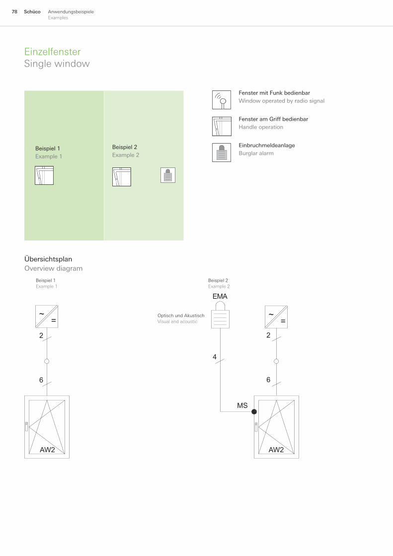
78 Schüco AnwendungsbeispieleExamples
EinzelfensterSinglewindow
ÜbersichtsplanOverviewdiagram
Beispiel1Example1
Beispiel2Example2
~=
~=
AW2
6
2
AW2
6
2
4
MS
EMA
OptischundAkustischVisualandacoustic
FenstermitFunkbedienbarWindowoperatedbyradiosignal
FensteramGriffbedienbarHandleoperation
EinbruchmeldeanlageBurglaralarm
Beispiel1Example1
Beispiel2Example2

79SchücoAnwendungsbeispieleExamples
Beispiel 1:EinzelfenstermitBedienungamGriff(vorOrt)
SchücoTipTronicermöglichtdieKippstel-lungaufTastendruckunddiekonventionelleDrehfunktionüberdenDrehgriff.KomplettverdecktliegenderBeschlag:keinevonaußenzugänglichenTeileaußerdemGriff.
Beispiel 2:EinzelfenstermitAnschlussanVdSEinbruch-meldeanlage
ZusätzlichzuBeispiel1mitkombinierterÖffnungsundVerschlussüberwachungmitMagnetschalter.SchließrollenmitintegriertenMagneterforderlich.
■
■
■
■
AnschlussplanCircuitdiagram
Beispiel1Example1
Beispiel2Example2
BU
S−A
BU
S−B
GN
D +
24V
SL-
2 S
L-1
BU
S−A
BU
S−B
GN
D +
24V
SL−
2 S
L−1
MS
28V+ −
VdS EMA28V+ −
Magnetschalterleitung4x0,14mm²magneticswitchescable4x0.14mm²
SchücoRundleitungmax.5,5mSchücoroundcablemax.5.5m
blau
/B
lue
rot
/Red
wei
ß/
Whi
te
wei
ß/
Whi
te
wei
ß/
Whi
te
wei
ß /
Whi
te
blau
/B
lue
rot
/Red
2x1,5mm²bis20m2x2,5mm²bis35m2x1.5mm²upto20m2x2.5mm²upto35m
2x1,5mm²bis20m2x2,5mm²bis35m2x1.5mm²upto20m2x2.5mm²upto35m
SchücoRundleitungmax.5,5mSchücoroundcablemax.5.5m
SchücoTipTronicFensterSchücoTipTronicwindow
SchücoTipTronicFensterSchücoTipTronicwindow
Example 1:Singlewindowwithhandleoperation(notremote)
SchücoTipTronicallowsthewindowtobetiltedatthepushofabutton,andopenedintheconventionalturnpositionusingthehandle.Fully concealed fittings: no components accessiblefromtheoutside,exceptthehandle.
Example 2:SinglewindowwithconnectiontoVdSburglaralarm
Asexample1,butwithcombinedmonitoringofopeningandclosingwithmagneticswitch.Lockingrollerswithintegratedmagnetarerequired.
■
■
■
■
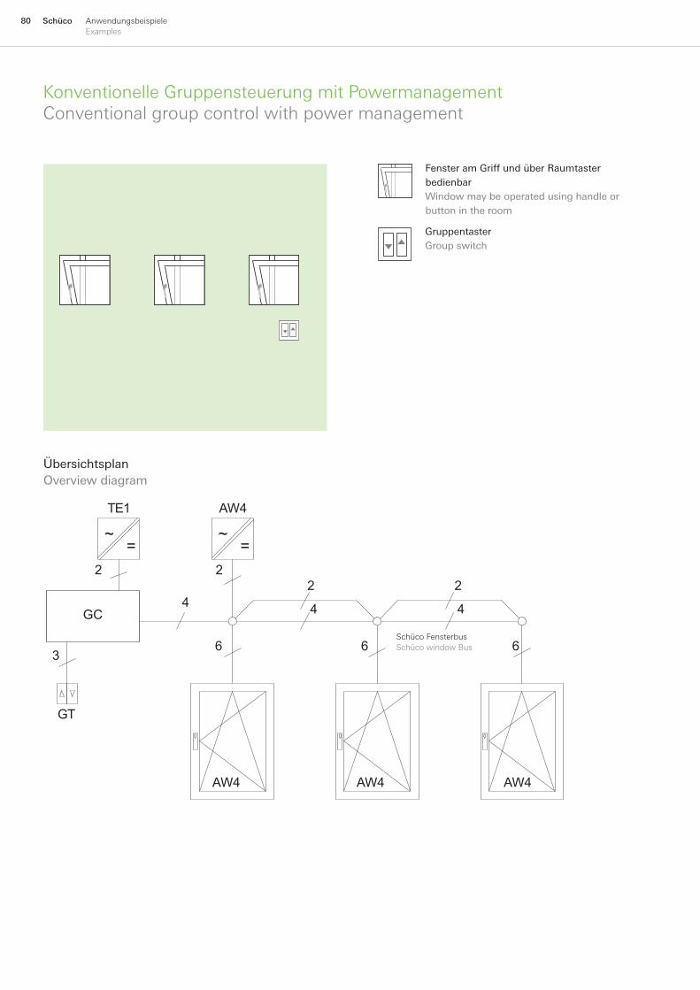
80 Schüco AnwendungsbeispieleExamples
KonventionelleGruppensteuerungmitPowermanagementConventionalgroupcontrolwithpowermanagement
ÜbersichtsplanOverviewdiagram
GC
AW4
AW4 AW4 AW4
4
3
2 22
4
66
2
4
6
GT
TE1
~=
~=
SchücoFensterbusSchücowindowBus
FensteramGriffundüberRaumtasterbedienbarWindowmaybeoperatedusinghandleorbuttonintheroom
GruppentasterGroupswitch
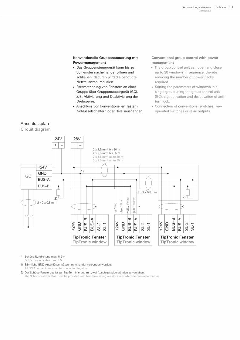
81SchücoAnwendungsbeispieleExamples
Konventionelle Gruppensteuerung mit Powermanagement
DasGruppensteuergerätkannbiszu30Fensternacheinanderöffnenundschließen,dadurchwirddiebenötigteNetzteilanzahlreduziert.ParametrierungvonFensternaneinerGruppeüberGruppensteuergerät(GC),z.B.AktivierungundDeaktivierungderDrehsperre.AnschlussvonkonventionellenTastern,
SchlüsselschalternoderRelaisausgängen.
■
■
■
AnschlussplanCircuitdiagram
BU
S−A
BU
S−B
GN
D +
24V
SL-
2 S
L-1
BU
S−A
BU
S−B
GN
D +
24V
SL-
2 S
L-1
BU
S−A
BU
S−B
GN
D +
24V
SL-
2 S
L-1
BUS−B
BUS−AGND+24V
+ −
28V+ −
24V
GC1)
2)2)
* * *
TipTronic FensterTipTronic window
TipTronic FensterTipTronic window
TipTronic FensterTipTronic window
gel
b/Y
ello
w
2x1,5mm²bis20m2x2,5mm²bis35m2x1.5mm²upto20m2x2.5mm²upto35m
rot
/Red
wei
ß/
Whi
te
blau
/B
lue
2x2x0,8mm
2x2x0,8mm
1) SämtlicheGND-Anschlüssemüssenmiteinanderverbundenwerden. AllGNDconnectionsmustbeconnectedtogether.
2) DerSchücoFensterbusistzurBus-TerminierungmitzweiAbschlusswiderständenzuversehen. TheSchücowindowBusmustbeprovidedwithtwoterminatingresistorswithwhichtoterminatetheBus.
* SchücoRundleitungmax.5,5m Schücoroundcablemax.5.5m
Conventional group control with power management
Thegroupcontrolunitcanopenandcloseupto30windowsinsequence,therebyreducingthenumberofpowerpacksrequired.Settingtheparametersofwindowsinasinglegroupusingthegroupcontrolunit(GC),e.g.activationanddeactivationofanti-turnlock.Connectionofconventionalswitches,key-operatedswitchesorrelayoutputs.
■
■
■
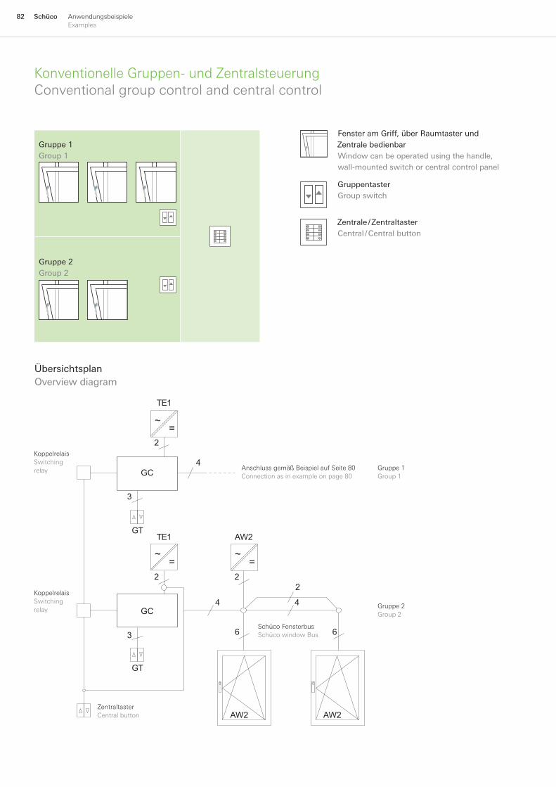
82 Schüco AnwendungsbeispieleExamples
KonventionelleGruppen-undZentralsteuerungConventionalgroupcontrolandcentralcontrol
ÜbersichtsplanOverviewdiagram
GC
GC
AW2
AW2 AW2
2
4
3
2
4
22
4
3 66
GT
GT
TE1
TE1
~=
~=
~=
ZentraltasterCentralbutton
AnschlussgemäßBeispielaufSeite80Connectionasinexampleonpage80
Gruppe1Group1
KoppelrelaisSwitchingrelay
Gruppe2Group2
KoppelrelaisSwitchingrelay
SchücoFensterbusSchücowindowBus
FensteramGriff,überRaumtasterundZentralebedienbarWindowcanbeoperatedusingthehandle,wall-mountedswitchorcentralcontrolpanel
GruppentasterGroupswitch
Zentrale/ZentraltasterCentral/Centralbutton
Gruppe1Group1
Gruppe2Group2
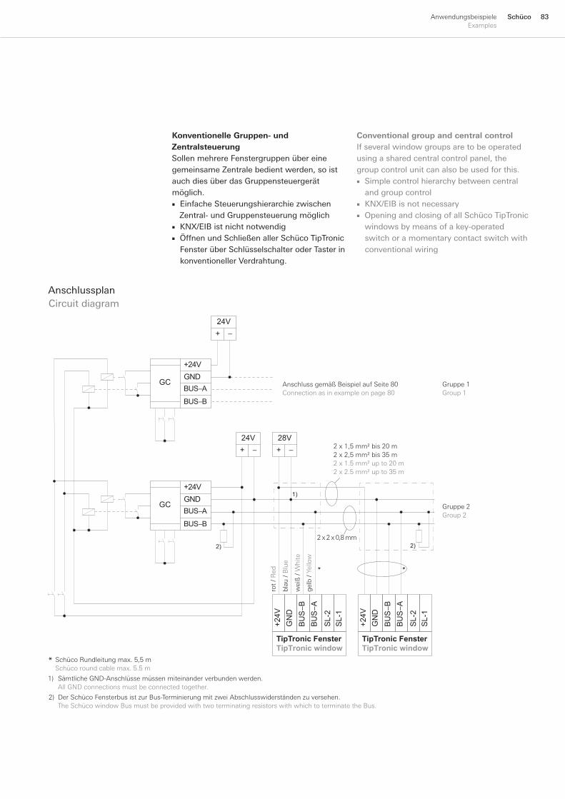
83SchücoAnwendungsbeispieleExamples
Konventionelle Gruppen- und ZentralsteuerungSollenmehrereFenstergruppenübereinegemeinsameZentralebedientwerden,soistauchdiesüberdasGruppensteuergerätmöglich.
EinfacheSteuerungshierarchiezwischenZentral-undGruppensteuerungmöglichKNX/EIBistnichtnotwendigÖffnenundSchließenallerSchücoTipTronicFensterüberSchlüsselschalteroderTasterinkonventionellerVerdrahtung.
■
■■
AnschlussplanCircuitdiagram
BUS−B
BUS−AGND+24V
GC
+ −
24V
BUS−B
BUS−AGND+24V
GC
+ −
24V+ −
28V
BU
S−A
BU
S−B
GN
D +
24V
SL-
2 S
L-1
TipTronic FensterTipTronic window
BU
S−A
BU
S−B
GN
D +
24V
SL-
2 S
L-1
1)
2)
**
2)
TipTronic FensterTipTronic window
2x1,5mm²bis20m2x2,5mm²bis35m2x1.5mm²upto20m2x2.5mm²upto35m
gel
b/Y
ello
w
rot
/ Red
wei
ß/
Whi
te
blau
/ B
lue
2x2x0,8mm
AnschlussgemäßBeispielaufSeite80Connectionasinexampleonpage80
Gruppe1Group1
Gruppe2Group2
1) SämtlicheGND-Anschlüssemüssenmiteinanderverbundenwerden. AllGNDconnectionsmustbeconnectedtogether.
2) DerSchücoFensterbusistzurBus-TerminierungmitzweiAbschlusswiderständenzuversehen. TheSchücowindowBusmustbeprovidedwithtwoterminatingresistorswithwhichtoterminatetheBus.
SchücoRundleitungmax.5,5mSchücoroundcablemax.5.5m
*
Conventional group and central controlIfseveralwindowgroupsaretobeoperatedusingasharedcentralcontrolpanel,thegroupcontrolunitcanalsobeusedforthis.
SimplecontrolhierarchybetweencentralandgroupcontrolKNX/EIBisnotnecessaryOpeningandclosingofallSchücoTipTronicwindowsbymeansofakey-operatedswitchoramomentarycontactswitchwithconventionalwiring
■
■■
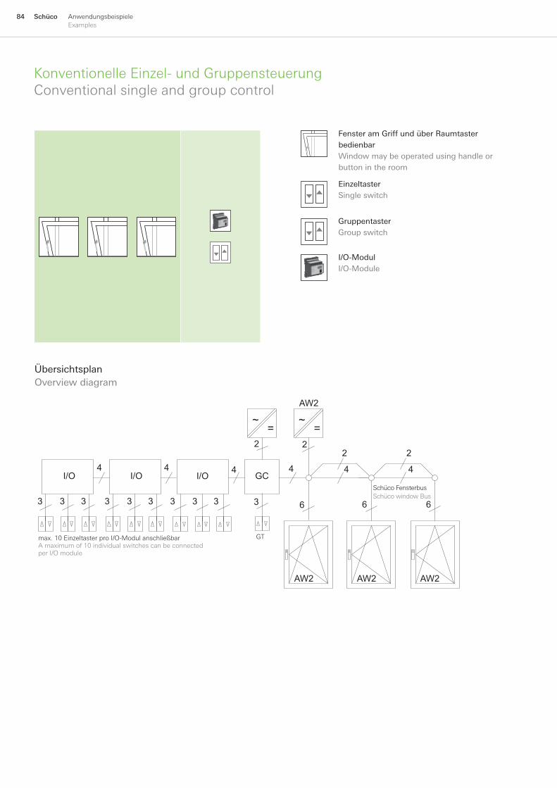
84 Schüco AnwendungsbeispieleExamples
ÜbersichtsplanOverviewdiagram
AW2
AW2 AW2 AW2
4
2
4
66
2
4
6
4I/O
3 3 3
I/O4
3 3 3
I/O
3 3 3
4GC
3
2 2
~=
~=
max.10EinzeltasterproI/O-ModulanschließbarAmaximumof10individualswitchescanbeconnectedperI/Omodule
GT
SchücoFensterbusSchücowindowBus
KonventionelleEinzel-undGruppensteuerungConventionalsingleandgroupcontrol
FensteramGriffundüberRaumtasterbedienbarWindowmaybeoperatedusinghandleorbuttonintheroom
EinzeltasterSingleswitch
I/O-ModulI/O-Module
GruppentasterGroupswitch
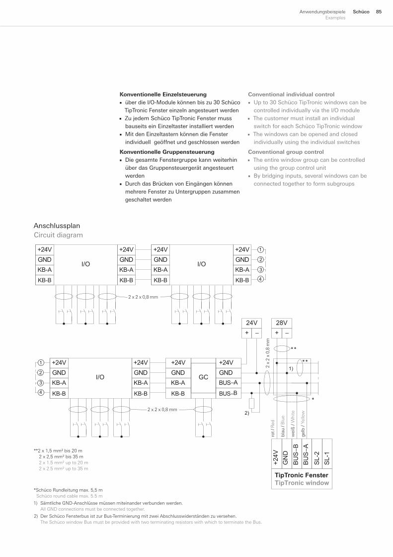
85SchücoAnwendungsbeispieleExamples
Konventionelle EinzelsteuerungüberdieI/O-Modulekönnenbiszu30SchücoTipTronicFenstereinzelnangesteuertwerdenZujedemSchücoTipTronicFenstermussbauseitseinEinzeltasterinstalliertwerdenMitdenEinzeltasternkönnendieFensterindividuellgeöffnetundgeschlossenwerden
Konventionelle GruppensteuerungDiegesamteFenstergruppekannweiterhinüberdasGruppensteuergerätangesteuertwerdenDurchdasBrückenvonEingängenkönnenmehrereFensterzuUntergruppenzusammengeschaltetwerden
■
■
■
■
■
1) SämtlicheGND-Anschlüssemüssenmiteinanderverbundenwerden. AllGNDconnectionsmustbeconnectedtogether.
2) DerSchücoFensterbusistzurBus-TerminierungmitzweiAbschlusswiderständenzuversehen. TheSchücowindowBusmustbeprovidedwithtwoterminatingresistorswithwhichtoterminatetheBus.
*SchücoRundleitungmax.5,5mSchücoroundcablemax.5.5m
AnschlussplanCircuitdiagram
−−
BU
S−A
BU
S−B
GN
D +
24V
SL-
2 S
L-1
TipTronic FensterTipTronic window
BUS−B
BUS−AGND+24V
+28V
+24V
GC
2)
I/OGND+24V
GND+24V
GND+24V1
2
3
4
I/OGND+24V
GND+24V
I/OGND+24V
KB-B
KB-AGND+24V 1
2
3
4KB-B
KB-A
KB-B
KB-A
KB-B
KB-A
KB-B
KB-A
KB-B
KB-A
KB-B
KB-A
1)
**2x1,5mm²bis20m2x2,5mm²bis35m2x1.5mm²upto20m2x2.5mm²upto35m
gel
b/Y
ello
w
rot/
Red
wei
ß/
Whi
te
blau
/B
lue
2x2x0,8mm
2x2x0,8mm
2x
2x
0,8
mm
**
**
*
Conventional individual controlUpto30SchücoTipTronicwindowscanbecontrolledindividuallyviatheI/OmoduleThecustomermustinstallanindividualswitchforeachSchücoTipTronicwindowThewindowscanbeopenedandclosedindividuallyusingtheindividualswitches
Conventional group controlTheentirewindowgroupcanbecontrolledusingthegroupcontrolunitBybridginginputs,severalwindowscanbeconnectedtogethertoformsubgroups
■
■
■
■
■
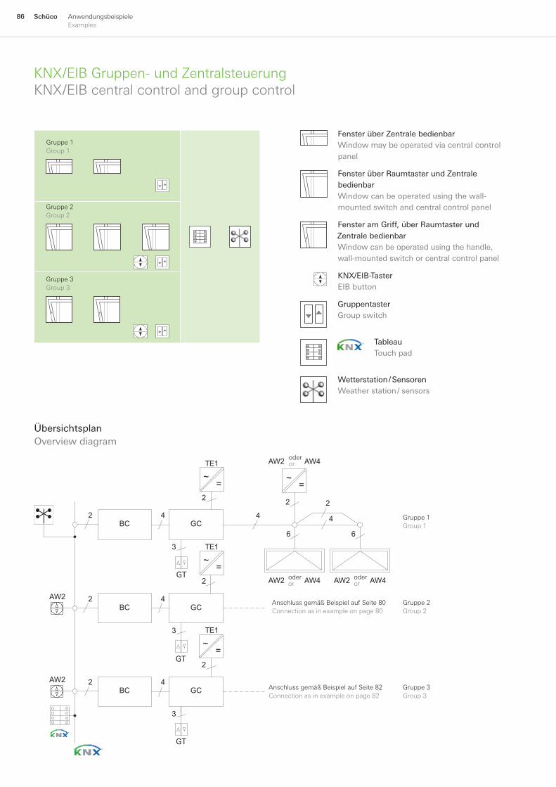
86 Schüco AnwendungsbeispieleExamples
ÜbersichtsplanOverviewdiagram
BC GC
BC GC
BC GC
2
2
2
2
2
4
4
4
3
4
3
4
22
6 6
2
AW2 AW4
TE1
TE1
AW2 AW4 AW2 AW4
AW2
AW2
TE1
3
~= ~
=
~=
~=
Gruppe1Group1
Gruppe2Group2
Gruppe3Group3
AnschlussgemäßBeispielaufSeite80Connectionasinexampleonpage80
AnschlussgemäßBeispielaufSeite82Connectionasinexampleonpage82
oderor
oderor
oderor
GT
GT
GT
KNX/EIBGruppen-undZentralsteuerungKNX/EIBcentralcontrolandgroupcontrol
GruppentasterGroupswitch
KNX/EIB-TasterEIBbutton
TableauTouchpad
FensterüberZentralebedienbarWindowmaybeoperatedviacentralcontrolpanel
FensterüberRaumtasterundZentralebedienbarWindowcanbeoperatedusingthewall-mountedswitchandcentralcontrolpanel
FensteramGriff,überRaumtasterundZentralebedienbarWindowcanbeoperatedusingthehandle,wall-mountedswitchorcentralcontrolpanel
Wetterstation/SensorenWeatherstation/sensors
Gruppe1Group1
Gruppe2Group2
Gruppe3Group3
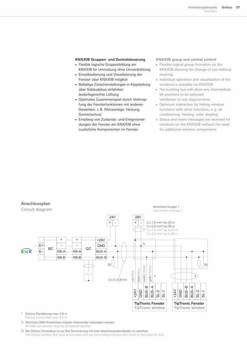
87SchücoAnwendungsbeispieleExamples
AnschlussplanCircuitdiagram
1) SämtlicheGND-Anschlüssemüssenmiteinanderverbundenwerden. AllGNDconnectionsmustbeconnectedtogether.
2) DerSchücoFensterbusistzurBus-TerminierungmitzweiAbschlusswiderständenzuversehen. TheSchücowindowBusmustbeprovidedwithtwoterminatingresistorswithwhichtoterminatetheBus.
KNX/EIB Gruppen- und ZentralsteuerungFlexiblelogischeGruppenbildungamKNX/EIBfürUmnutzungohneUmverdrahtungEinzelbedienungundVisualisierungderFensterüberKNX/EIBmöglichBeliebigeZwischenstellungeninKippstellungüberGebäudebusanfahrbar:bedarfsgerechteLüftungOptimalesZusammenspieldurchVerknüp-fungderFensterfunktionenmitanderenGewerken,z.B.Klimaanlage,Heizung,SonnenschutzEmpfangvonZustands-undEreignismel-dungenderFensteramKNX/EIBohnezusätzlicheKomponentenimFenster.
■
■
■
■
■
* SchücoRundleitungmax.5,5m Schücoroundcablemax.5.5m
BU
S−A
BU
S−B
GN
D +
24V
SL-
2 S
L-1
BU
S−A
BU
S−B
GN
D +
24V
SL-
2 S
L-1
1)
2) 2)
BUS−B
BUS−A
GND+24V
GCBCE+E−
+−
+−
+ −+ −
24V 28V
**
TipTronic FensterTipTronic window
TipTronic FensterTipTronic window
KB-B
KB-A
KB-B
KB-A
2x1,5mm²bis20m2x2,5mm²bis35m2x1.5mm²upto20m2x2.5mm²upto35m
gel
b/Y
ello
w
rot/
Red
wei
ß/
Whi
te
blau
/B
lue
2x2x0,8mm
AnschlussGruppe1Connectionofgroup1
KNX/EIB group and central controlFlexiblelogicalgroupformationontheKNX/EIBallowingforchangeofusewithoutrewiringIndividualoperationandvisualisationofthewindowsispossibleviaKNX/EIBThebuildingbuswillallowanyintermediatetiltpositionstobeselected:ventilationtosuitrequirementsOptimuminteractionbylinkingwindowfunctionswithotherfunctions,e.g.airconditioning,heating,solarshadingStatusandeventmessagesarereceivedforwindowsontheKNX/EIBwithouttheneedforadditionalwindowcomponents
■
■
■
■
■
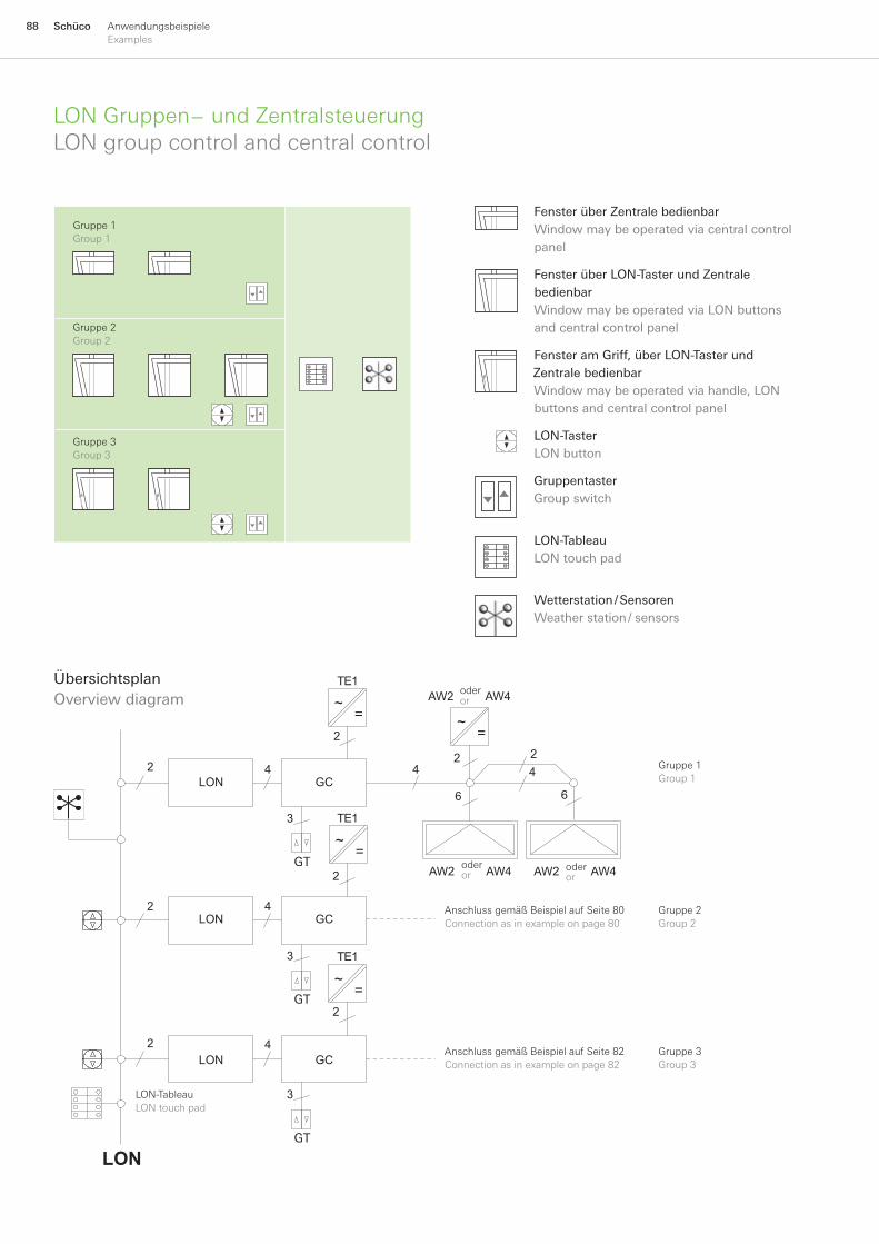
88 Schüco AnwendungsbeispieleExamples
LON Gruppen− und ZentralsteuerungLONgroupcontrolandcentralcontrol
ÜbersichtsplanOverviewdiagram
LON GC
LON GC
LON GC
2
2
2
2
4
4
4
2
2
2 24
66
4
LON
TE1
TE1
TE1
3
3
3
AW2 AW4 AW2 AW4
AW2 AW4~= ~
=
~=
~=
Gruppe1Group1
Gruppe2Group2
Gruppe3Group3
AnschlussgemäßBeispielaufSeite80Connectionasinexampleonpage80
AnschlussgemäßBeispielaufSeite82Connectionasinexampleonpage82
LON-TableauLONtouchpad
oderor
oderor
oderor
GT
GT
GT
GruppentasterGroupswitch
LON-TableauLONtouchpad
LON-TasterLONbutton
FensteramGriff,überLON-TasterundZentralebedienbarWindowmaybeoperatedviahandle,LONbuttonsandcentralcontrolpanel
FensterüberLON-TasterundZentralebedienbarWindowmaybeoperatedviaLONbuttonsandcentralcontrolpanel
Wetterstation/SensorenWeatherstation/sensors
FensterüberZentralebedienbarWindowmaybeoperatedviacentralcontrolpanel
Gruppe1Group1
Gruppe2Group2
Gruppe3Group3
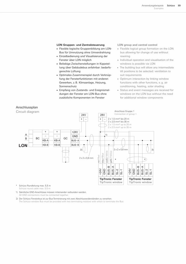
89SchücoAnwendungsbeispieleExamples
1) SämtlicheGND-Anschlüssemüssenmiteinanderverbundenwerden. AllGNDconnectionsmustbeconnectedtogether.
2) DerSchücoFensterbusistzurBus-TerminierungmitzweiAbschlusswiderständenzuversehen. TheSchücowindowBusmustbeprovidedwithtwoterminatingresistorswithwhichtoterminatetheBus.
AnschlussGruppe1Connectionofgroup1
BU
S−A
BU
S−B
GN
D +
24V
SL-
2 S
L-1
BU
S−A
BU
S−B
GN
D +
24V
SL-
2 S
L-1
1)
2) 2)
B
A
AB
+ −+ −
24V 28V
*
LON
*
TipTronic FensterTipTronic window
TipTronic FensterTipTronic window
BUS−
BUS−
GND+24V
GCBC
+−
+−
KB-B
KB-A
KB-B
KB-A
2x1,5mm²bis20m2x2,5mm²bis35m2x1.5mm²upto20m2x2.5mm²upto35m
gel
b/Y
ello
w
rot/
Red
wei
ß/
Whi
te
blau
/B
lue
2x2x0,8mm
2x2x0,8mm
* SchücoRundleitungmax.5,5m Schücoroundcablemax.5.5m
AnschlussplanCircuitdiagram
LON Gruppen- und ZentralsteuerungFlexiblelogischeGruppenbildungamLON-BusfürUmnutzungohneUmverdrahtungEinzelbedienungundVisualisierungderFensterüberLONmöglichBeliebigeZwischenstellungeninKippstel-lungüberGebäudebusanfahrbar:bedarfs-gerechteLüftungOptimalesZusammenspieldurchVerknüp-fungderFensterfunktionenmitanderenGewerken,z.B.Klimaanlage,Heizung,SonnenschutzEmpfangvonZustands-undEreignismel-dungenderFensteramLON-BusohnezusätzlicheKomponentenimFenster
■
■
■
■
■
LON group and central controlFlexiblelogicalgroupformationontheLONbusallowingforchangeofusewithoutrewiringIndividualoperationandvisualisationofthewindowsispossibleviaLONThebuildingbuswillallowanyintermediatetiltpositionstobeselected:ventilationtosuitrequirementsOptimuminteractionbylinkingwindowfunctionswithotherfunctions,e.g.airconditioning,heating,solarshadingStatusandeventmessagesarereceivedforwindowsontheLONbuswithouttheneedforadditionalwindowcomponents
■
■
■
■
■
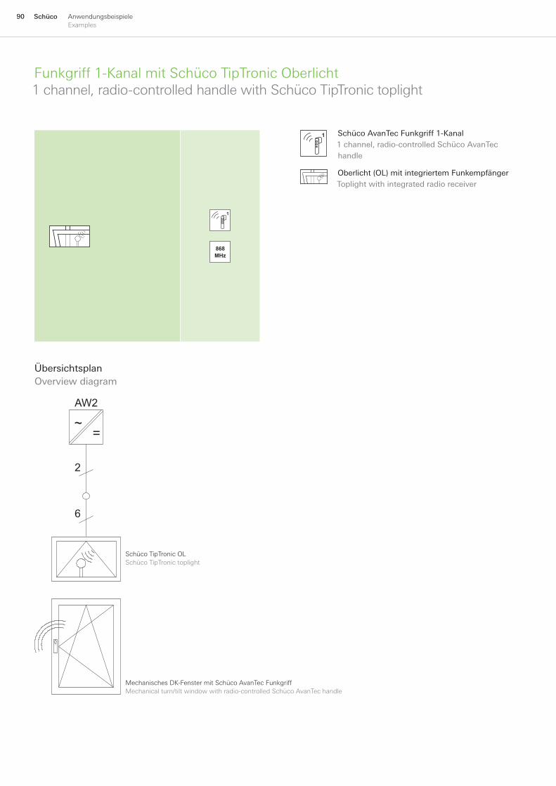
90 Schüco AnwendungsbeispieleExamples
Funkgriff1-KanalmitSchücoTipTronicOberlicht1channel,radio-controlledhandlewithSchücoTipTronictoplight
ÜbersichtsplanOverviewdiagram
6
2
AW2
~=
SchücoTipTronicOLSchücoTipTronictoplight
MechanischesDK-FenstermitSchücoAvanTecFunkgriffMechanicalturn/tiltwindowwithradio-controlledSchücoAvanTechandle
SchücoAvanTecFunkgriff1-Kanal1channel,radio-controlledSchücoAvanTechandle
Oberlicht(OL)mitintegriertemFunkempfängerToplightwithintegratedradioreceiver
868MHz

91SchücoAnwendungsbeispieleExamples
Schüco TipTronic Oberlicht über Funk bedienbar
SchücoTipTronicOberlichtfensterwirddurchdasFunksignaldesSchücoAvanTecFunkgriffsgeöffnet.
■
AnschlussplanCircuitdiagram
BU
S−A
BU
S−B
GN
D +
24V
SL−
2 S
L−1
28V+ −
FETipTronic FensterTipTronic window
247 574247 575247 576
247 578247 577
1
2x1,5mm²bis20m2x2,5mm²bis35m2x1.5mm²upto20m2x2.5mm²upto35m
SchücoRundleitungmax.5,5mSchücoroundcablemax.5.5m
rot/
Red
blau
/B
lue
Radio-controlled Schüco TipTronic toplightSchücoTipTronictoplightwindowisopenedbytheradiosignalfromtheradio-controlledSchücoAvanTechandle.
■
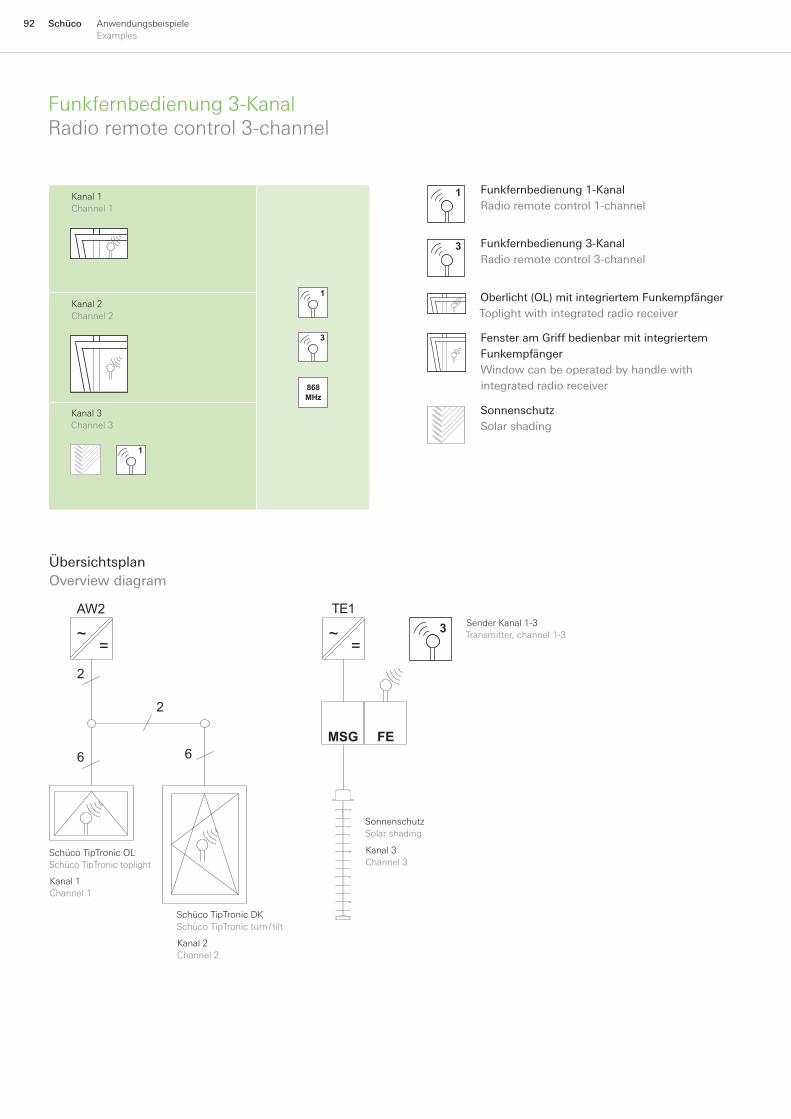
92 Schüco AnwendungsbeispieleExamples
Funkfernbedienung3-KanalRadioremotecontrol3-channel
ÜbersichtsplanOverviewdiagram
MSG FE6
2
AW2
2
6
3TE1
~=
~=
SchücoTipTronicOLSchücoTipTronictoplight
SchücoTipTronicDKSchücoTipTronicturn/tilt
SonnenschutzSolarshading
Kanal1Channel1
Kanal3Channel3
Kanal2Channel2
SenderKanal1-3Transmitter,channel1-3
Funkfernbedienung3-KanalRadioremotecontrol3-channel
Oberlicht(OL)mitintegriertemFunkempfängerToplightwithintegratedradioreceiver
SonnenschutzSolarshading
FensteramGriffbedienbarmitintegriertemFunkempfängerWindowcanbeoperatedbyhandlewithintegratedradioreceiver
Funkfernbedienung1-KanalRadioremotecontrol1-channel
1
3
Kanal1Channel1
3
1
868MHz
Kanal2Channel2
Kanal3Channel3
1
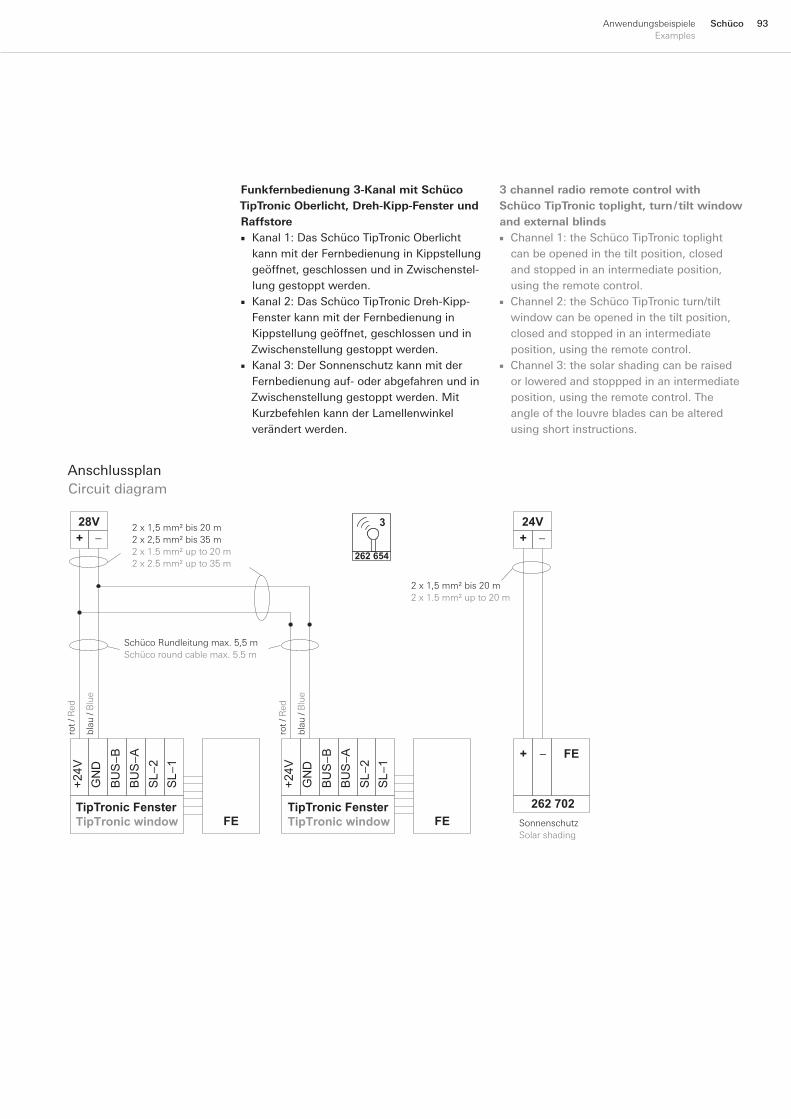
93SchücoAnwendungsbeispieleExamples
Funkfernbedienung 3-Kanal mit Schüco TipTronic Oberlicht, Dreh-Kipp-Fenster und Raffstore
Kanal1:DasSchücoTipTronicOberlichtkannmitderFernbedienunginKippstellunggeöffnet,geschlossenundinZwischenstel-lunggestopptwerden.Kanal2:DasSchücoTipTronicDreh-Kipp-FensterkannmitderFernbedienunginKippstellunggeöffnet,geschlossenundinZwischenstellunggestopptwerden.Kanal3:DerSonnenschutzkannmitderFernbedienungauf-oderabgefahrenundinZwischenstellunggestopptwerden.MitKurzbefehlenkannderLamellenwinkelverändertwerden.
■
■
■
AnschlussplanCircuitdiagram
−B B
US−
A B
US
GN
D +
24V
SL−
2 S
L−1
FE
BU
S−A
BU
S−B
GN
D +
24V
SL−
2 S
L−1
28V+ −
FE
24V+ −
262 702
FE−+
TipTronic FensterTipTronic window
TipTronic FensterTipTronic window
3
262 654
2x1,5mm²bis20m2x2,5mm²bis35m2x1.5mm²upto20m2x2.5mm²upto35m
SchücoRundleitungmax.5,5mSchücoroundcablemax.5.5m
rot/
Red
blau
/B
lue
rot/
Red
blau
/B
lue
SonnenschutzSolarshading
2x1,5mm²bis20m2x1.5mm²upto20m
3 channel radio remote control with Schüco TipTronic toplight, turn / tilt window and external blinds
Channel1:theSchücoTipTronictoplightcanbeopenedinthetiltposition,closedandstoppedinanintermediateposition,usingtheremotecontrol.Channel2:theSchücoTipTronicturn/tiltwindowcanbeopenedinthetiltposition,closedandstoppedinanintermediateposition,usingtheremotecontrol.Channel3:thesolarshadingcanberaisedorloweredandstopppedinanintermediateposition,usingtheremotecontrol.Theangleofthelouvrebladescanbealteredusingshortinstructions.
■
■
■
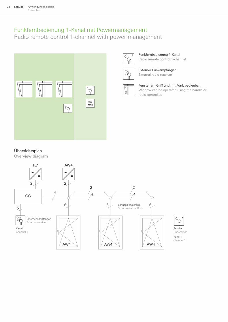
94 Schüco AnwendungsbeispieleExamples
Funkfernbedienung1-KanalmitPowermanagementRadioremotecontrol1-channelwithpowermanagement
ÜbersichtsplanOverviewdiagram
GC
AW4
AW4 AW4 AW4
4
5
22
4
66
2
4
6
2
TE1
~=
~=
SchücoFensterbusSchücowindowBus
Kanal1Channel1
ExternerEmpfängerExternalreceiver
SenderTransmitter
Kanal1Channel1
FensteramGriffundmitFunkbedienbarWindowcanbeoperatedusingthehandleorradio-controlled
ExternerFunkempfängerExternalradioreceiver
Funkfernbedienung1-KanalRadioremotecontrol1-channel
1
1
868MHz

95SchücoAnwendungsbeispieleExamples
Fenstergruppe mit Powermanagement über Funk bedienbar
DieSchücoTipTronicFensterkönnengeöffnetbzw.geschlossenwerden.EinStoppeninZwischenstellungensowieeineEinzelsteuerungistnichtmöglich.EsfahrenimmeralleOberlichternacheinander.EsisteinNetzteilfürdieFenstergruppebismax.30Fenstervorzusehen(Powermanagement).
■
■
■
1) SämtlicheGND-Anschlüssemüssenmiteinanderverbundenwerden. AllGNDconnectionsmustbeconnectedtogether.
2) DerSchücoFensterbusistzurBus-TerminierungmitzweiAbschlusswiderständenzuversehen. TheSchücowindowBusmustbeprovidedwithtwoterminatingresistorswithwhichtoterminatetheBus.
* SchücoRundleitungmax.5,5m Schücoroundcablemax.5.5m
AnschlussplanCircuitdiagram
K2−
NO
K2−
C 0
V
K1−
C K
1−N
O
262 653
BU
S−A
BU
S−B
GN
D +
24V
SL-
2 S
L-1
BU
S−A
BU
S−B
GN
D +
24V
SL-
2 S
L-1
BU
S−A
BU
S−B
GN
D +
24V
SL-
2 S
L-1
BUS−B
BUS−AGND+24V
+ −
28V+ −
24V
GC1)
2)
2)
262 634
***
6 7 8
TipTronic FensterTipTronic window
TipTronic FensterTipTronic window
TipTronic FensterTipTronic window
+24
V
2x1,5mm²bis20m2x2,5mm²bis35m2x1.5mm²upto20m2x2.5mm²upto35m
gel
b/Y
ello
w
rot/
Red
wei
ß/
Whi
te
blau
/B
lue
2x2x0,8mm
2x2x0,8mm
Radio-controlled window group with power management
TheSchücoTipTronicwindowscanbeopenedandclosed.Itisnotpossibletostoptheminintermediatepositionsnortocontrolthemindividually.Alltoplightsarealwaysoperatedinsequence.Onepowerpackisrequiredforthewindowgroupuptoamax.of30windows(powermanagement).
■
■
■

96 Schüco AnwendungsbeispieleExamples
FunkgruppensteuerungmitFunkgrifffürFensterRadio-controlledgroupcontrolwithradio-controlledhandlefürwindows
ÜbersichtsplanOverviewdiagram
AW2
2
6
AW2
2
6
AW2
2
6
~=
~=
~=
AW2
2
6
AW2
2
6
AW2
2
6
~=
~=
~=
SenderTransmitter
Kanal3Channel3
Kanal1Channel1
Kanal2Channel2
Kanal3Channel3
SenderTransmitter
Kanal1Channel1
Kanal1Channel1
Kanal1Channel1
Kanal1Channel1
SchücoAvanTecFunkgriff1-Kanal1channel,radio-controlledSchücoAvanTechandle
1
SchücoAvanTecFunkgriff3-Kanal3channel,radio-controlledSchücoAvanTechandle
3
Oberlicht(OL)mitintegriertemFunkempfängerToplightwithintegratedradioreceiver
1
3
868MHz

97SchücoAnwendungsbeispieleExamples
AnschlussplanCircuitdiagram
BU
S−A
BU
S−B
GN
D +
24V
SL-
2 S
L-1
28V+ −
BU
S−A
BU
S−B
GN
D +
24V
SL-
2 S
L-1
28V+ −
FE BU
S−A
BU
S−B
GN
D +
24V
SL-
2 S
L-1
FEFE
TipTronic FensterTipTronic window
TipTronic FensterTipTronic window
TipTronic FensterTipTronic window
3
247 613247 614247 615
247 617247 616
28V+ −
247 574247 575247 576
247 578247 577
12x1,5mm²bis20m2x2,5mm²bis35m2x1.5mm²upto20m2x2.5mm²upto35m
SchücoRundleitungmax.5,5mSchücoroundcablemax.5.5m
rot/
Red
blau
/B
lue
SchücoRundleitungmax.5,5mSchücoroundcablemax.5.5m
SchücoRundleitungmax.5,5mSchücoroundcablemax.5.5m
rot/
Red
blau
/B
lue
rot/
Red
blau
/B
lue
*
* * *
Funkgruppensteuerung mit Schüco AvanTec Funkgriff 1-Kanal mit 3 gemein-sam angesteuerten Schüco TipTronic Oberlichtern (ohne Powermanagement)
DieOberlichterkönnenüberdenSchücoAvanTecFunkgriffgleichzeitiggeöffnet,geschlossenundinZwischenstellungengestopptwerden.EineEinzelsteuerungistnichtmöglich.EsfahrenimmeralleOberlichtergleichzeitig.FürjedesOberlichtisteinseparatesNetzteilvorzusehen(keinPowermanagementmöglich).
■
■
Funkgruppensteuerung mit Schüco AvanTec Funkgriff 3-Kanal mit 3 einzeln angesteuerten Schüco TipTronic Oberlich-tern (ohne Powermanagement)
DieOberlichterkönnenüberdenSchücoAvanTecFunkgriffeinzelngeöffnet,ge-schlossenundinZwischenstellungengestopptwerden.DieAnzahlderFensterjeGruppeistabhängigvonderReichweite.
■
■
Radio-controlled group control with radio-controlled Schüco AvanTec handle 1 channel with 3 Schüco TipTronic top-lights controlled together (without power management)
Thetoplightscanbesimultaneouslyopened,closedorstoppedinintermediatepositionsusingtheradio-controlledSchücoAvanTechandle.Individualcontrolisnotpossible.Alltoplightsarealwaysoperatedatthesametime.Aseparatepowerpackisrequiredforeachtoplight(nopowermanagementpossible).
■
■
Radio-controlled group control with radio-controlled Schüco AvanTec handle 3 channel with 3 Schüco TipTronic toplights controlled individually (without power management)
Thetoplightscanbeindividuallyopened,closedorstoppedinintermediatepositionsusingtheradio-controlledSchücoAvanTechandle.Thenumberofwindowspergroupwilldependontherange.
■
■

98 Schüco AnwendungsbeispieleExamples
FunkgruppensteuerungmitFunkgriff3-KanalRadio-controlledgroupcontrolwith3channel,radio-controlledhandle
ÜbersichtsplanOverviewdiagram
MSG FE
AW2
6
2
FE
K2
2
TE1 TE1
~=
~=
~=
SonnenschutzSolarshading
Gruppe1Group1
Gruppe2Group2
Gruppe3Group3
BeleuchtungLighting
SchücoAvanTecFunkgriff3-Kanal3channel,radio-controlledSchücoAvanTechandle
3
SonnenschutzSolarshading
BeleuchtungHaus,Garten,usw.Lightingforhouse,gardenetc.
Oberlicht(OL)mitintegriertemFunkempfängerToplightwithintegratedradioreceiver
IntegrierterFunkempfängerIntegratedradioreceiver
Gruppe1Group1
3
868MHz
Gruppe2Group2
Gruppe3Group3
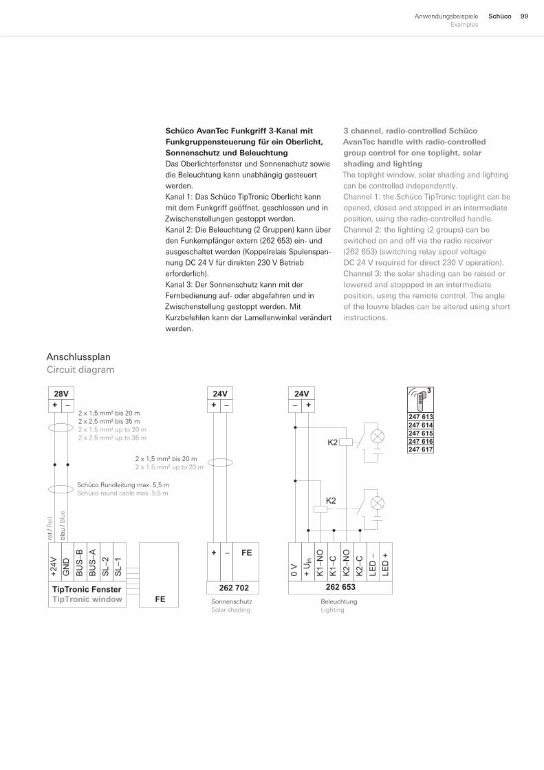
99SchücoAnwendungsbeispieleExamples
Schüco AvanTec Funkgriff 3-Kanal mit Funkgruppensteuerung für ein Oberlicht, Sonnenschutz und BeleuchtungDasOberlichterfensterundSonnenschutzsowiedieBeleuchtungkannunabhängiggesteuertwerden.Kanal1:DasSchücoTipTronicOberlichtkannmitdemFunkgriffgeöffnet,geschlossenundinZwischenstellungengestopptwerden.Kanal2:DieBeleuchtung(2Gruppen)kannüberdenFunkempfängerextern(262653)ein-undausgeschaltetwerden(KoppelrelaisSpulenspan-nungDC24Vfürdirekten230VBetrieberforderlich).Kanal3:DerSonnenschutzkannmitderFernbedienungauf-oderabgefahrenundinZwischenstellunggestopptwerden.MitKurzbefehlenkannderLamellenwinkelverändertwerden.
AnschlussplanCircuitdiagram
SonnenschutzSolarshading
24V+ −
262 702
FE−+
3
247 613247 614247 615
247 617247 616
BU
S−A
BU
S−B
GN
D +
24V
SL−
2 S
L−1
28V+ −
FETipTronic FensterTipTronic window
K1−
C K
1−N
O+
Uin
0 V
K2−
NO
K2−
C
24V+−
262 653
LED−
LE
D +
K2
K2
rot/
Red
blau
/B
lue
2x1,5mm²bis20m2x2,5mm²bis35m2x1.5mm²upto20m2x2.5mm²upto35m
SchücoRundleitungmax.5,5mSchücoroundcablemax.5.5m
2x1,5mm²bis20m2x1.5mm²upto20m
BeleuchtungLighting
3 channel, radio-controlled Schüco AvanTec handle with radio-controlled group control for one toplight, solar shading and lightingThetoplightwindow,solarshadingandlightingcanbecontrolledindependently.Channel1:theSchücoTipTronictoplightcanbeopened,closedandstoppedinanintermediateposition,usingtheradio-controlledhandle.Channel2:thelighting(2groups)canbeswitchedonandoffviatheradioreceiver(262653)(switchingrelayspoolvoltageDC24Vrequiredfordirect230Voperation).Channel3:thesolarshadingcanberaisedorloweredandstopppedinanintermediateposition,usingtheremotecontrol.Theangleofthelouvrebladescanbealteredusingshortinstructions.
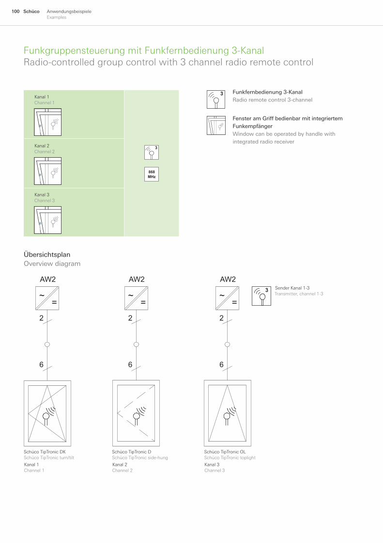
100 Schüco AnwendungsbeispieleExamples
FunkgruppensteuerungmitFunkfernbedienung3-KanalRadio-controlledgroupcontrolwith3channelradioremotecontrol
ÜbersichtsplanOverviewdiagram
AW2
6
2
3
AW2
6
2
AW2
6
2
~=
~=
~=
SchücoTipTronicDSchücoTipTronicside-hung
SchücoTipTronicOLSchücoTipTronictoplight
SchücoTipTronicDKSchücoTipTronicturn/tilt
Kanal1Channel1
Kanal3Channel3
Kanal2Channel2
SenderKanal1-3Transmitter,channel1-3
Funkfernbedienung3-KanalRadioremotecontrol3-channel
3
FensteramGriffbedienbarmitintegriertemFunkempfängerWindowcanbeoperatedbyhandlewithintegratedradioreceiver
Kanal1Channel1
3
868MHz
Kanal2Channel2
Kanal3Channel3
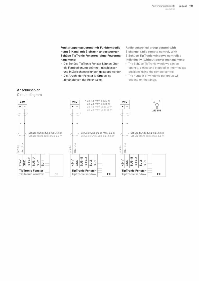
101SchücoAnwendungsbeispieleExamples
Funkgruppensteuerung mit Funkfernbedie-nung 3-Kanal mit 3 einzeln angesteuerten Schüco TipTronic Fenstern (ohne Powerma-nagement)
DieSchücoTipTronicFensterkönnenüberdieFernbedienunggeöffnet,geschlossenundinZwischenstellungengestopptwerdenDieAnzahlderFensterjeGruppeistabhängigvonderReichweite
■
■
AnschlussplanCircuitdiagram
BU
S−A
BU
S−B
GN
D +
24V
SL-
2 S
L-1
28V+ −
BU
S−A
BU
S−B
GN
D +
24V
SL-
2 S
L-1
28V+ −
FE
BU
S−A
BU
S−B
GN
D +
24V
SL-
2 S
L-1
28V+ −
FEFETipTronic FensterTipTronic window
TipTronic FensterTipTronic window
TipTronic FensterTipTronic window
262 654
32x1,5mm²bis20m2x2,5mm²bis35m2x1.5mm²upto20m2x2.5mm²upto35m
SchücoRundleitungmax.5,5mSchücoroundcablemax.5.5m
rot/
Red
blau
/B
lue
SchücoRundleitungmax.5,5mSchücoroundcablemax.5.5m
SchücoRundleitungmax.5,5mSchücoroundcablemax.5.5m
rot/
Red
blau
/B
lue
rot/
Red
blau
/B
lue
*
* * *
Radio-controlled group control with 3 channel radio remote control, with 3 Schüco TipTronic windows controlled individually (without power management)
TheSchücoTipTronicwindowscanbeopened,closedandstoppedinintermediatepositionsusingtheremotecontrol.Thenumberofwindowspergroupwilldependontherange.
■
■

102 Schüco AnwendungsbeispieleExamples
FenstergruppemitmehrerenNetzteilenWindowgroupwithseveralpowerpacks
GC
AW2
AW2 AW2 AW2
4
3
2 22
4
66
2
4
6
GT
TE1 AW2
AW2 AW2 AW2
4
2
4
66
2
4
6
2
~=
~=
~=
ÜbersichtsplanOverviewdiagram
GruppentasterGroupswitch
NetzteilPowerpack~
FensteramGriffbedienbarHandleoperation~
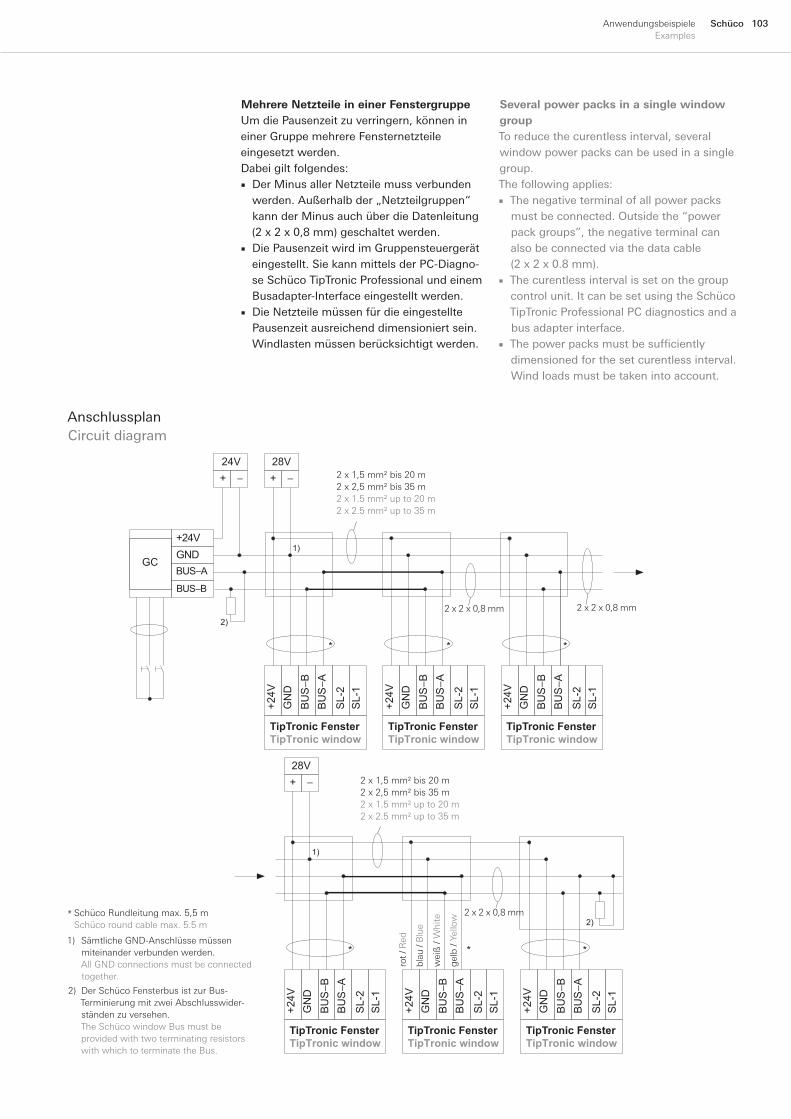
103SchücoAnwendungsbeispieleExamples
Mehrere Netzteile in einer FenstergruppeUmdiePausenzeitzuverringern,könnenineinerGruppemehrereFensternetzteileeingesetztwerden.Dabeigiltfolgendes:
DerMinusallerNetzteilemussverbundenwerden.Außerhalbder„Netzteilgruppen“kannderMinusauchüberdieDatenleitung(2x2x0,8mm)geschaltetwerden.DiePausenzeitwirdimGruppensteuergeräteingestellt.SiekannmittelsderPC-Diagno-seSchücoTipTronicProfessionalundeinemBusadapter-Interfaceeingestelltwerden.DieNetzteilemüssenfürdieeingestelltePausenzeitausreichenddimensioniertsein.Windlastenmüssenberücksichtigtwerden.
■
■
■
AnschlussplanCircuitdiagram
1) SämtlicheGND-Anschlüssemüssenmiteinanderverbundenwerden.AllGNDconnectionsmustbeconnectedtogether.
2) DerSchücoFensterbusistzurBus-TerminierungmitzweiAbschlusswider-ständenzuversehen.
TheSchücowindowBusmustbe providedwithtwoterminatingresistors withwhichtoterminatetheBus.
SchücoRundleitungmax.5,5mSchücoroundcablemax.5.5m
*
BU
S−A
BU
S−B
GN
D +
24V
SL-
2 S
L-1
BU
S−A
BU
S−B
GN
D +
24V
SL-
2 S
L-1
BU
S−A
BU
S−B
GN
D +
24V
SL-
2 S
L-1
BUS−B
BUS−AGND+24V
+ −
28V+ −
24V
GC
2)
* *
TipTronic FensterTipTronic window
TipTronic FensterTipTronic window
TipTronic FensterTipTronic window
*
1)
BU
S−A
BU
S−B
GN
D +
24V
SL-
2 S
L-1
1)
2)
*
TipTronic FensterTipTronic window
BU
S−A
BU
S−B
GN
D +
24V
SL-
2 S
L-1
BU
S−A
BU
S−B
GN
D +
24V
SL-
2 S
L-1
+ −
28V
* *
TipTronic FensterTipTronic window
TipTronic FensterTipTronic window
2x1,5mm²bis20m2x2,5mm²bis35m2x1.5mm²upto20m2x2.5mm²upto35m
gel
b/Y
ello
w
rot/
Red
wei
ß/
Whi
te
blau
/B
lue
2x2x0,8mm2x2x0,8mm
2x2x0,8mm
2x1,5mm²bis20m2x2,5mm²bis35m2x1.5mm²upto20m2x2.5mm²upto35m
Several power packs in a single window groupToreducethecurentlessinterval,severalwindowpowerpackscanbeusedinasinglegroup.Thefollowingapplies:
Thenegativeterminalofallpowerpacksmustbeconnected.Outsidethe“powerpackgroups”,thenegativeterminalcanalsobeconnectedviathedatacable(2x2x0.8mm).Thecurentlessintervalissetonthegroupcontrolunit.ItcanbesetusingtheSchücoTipTronicProfessionalPCdiagnosticsandabusadapterinterface.The power packs must be sufficiently dimensionedforthesetcurentlessinterval.Windloadsmustbetakenintoaccount.
■
■
■
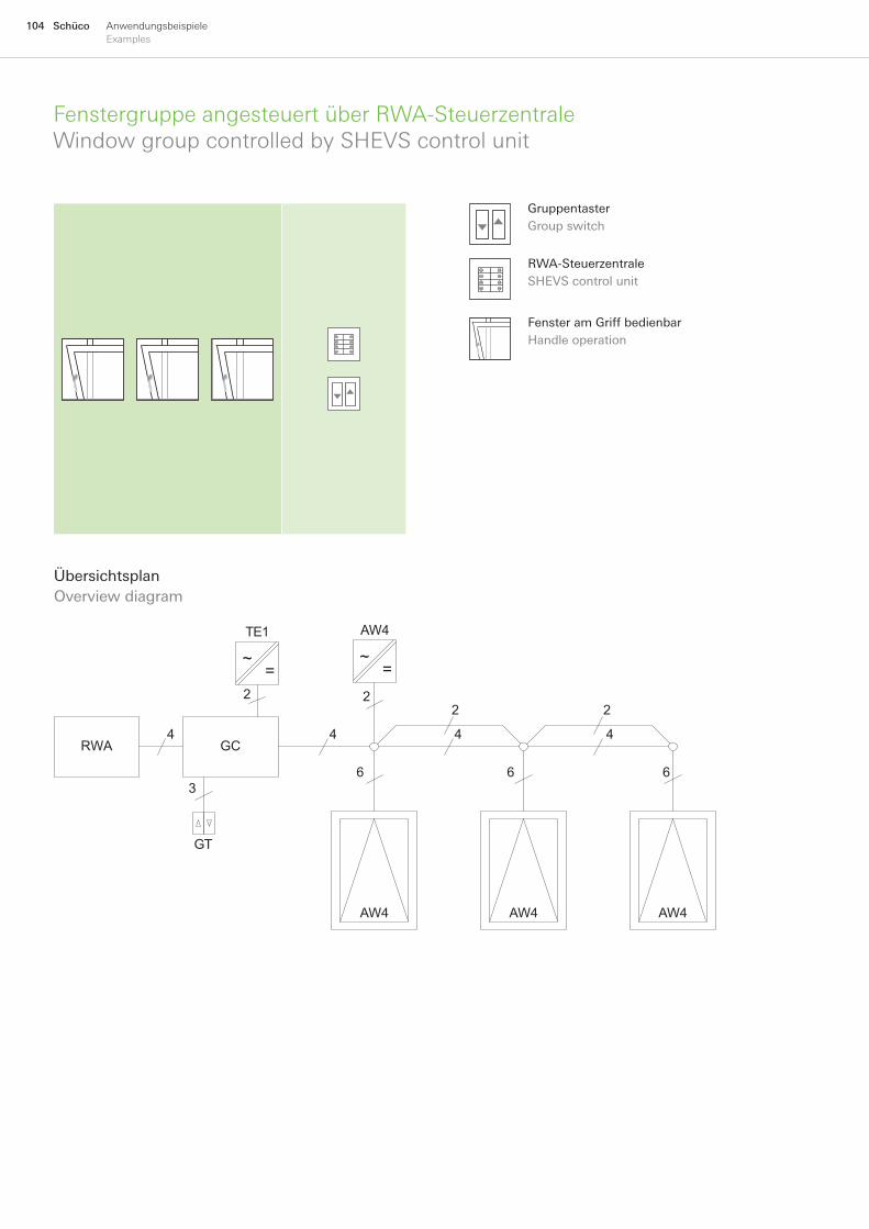
104 Schüco AnwendungsbeispieleExamples
FenstergruppeangesteuertüberRWA-SteuerzentraleWindowgroupcontrolledbySHEVScontrolunit
ÜbersichtsplanOverviewdiagram
GC
AW4
AW4 AW4 AW4
3
2
4
66
2
4
6
GT
TE1
RWA
22
44
~=
~=
RWA-SteuerzentraleSHEVScontrolunit
GruppentasterGroupswitch
FensteramGriffbedienbarHandleoperation
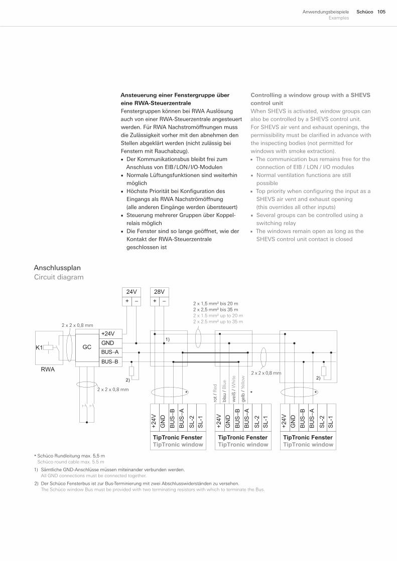
105SchücoAnwendungsbeispieleExamples
Ansteuerung einer Fenstergruppe über eine RWA-SteuerzentraleFenstergruppenkönnenbeiRWAAuslösungauchvoneinerRWA-Steuerzentraleangesteuertwerden.FürRWANachstromöffnungenmussdieZulässigkeitvorhermitdenabnehmendenStellenabgeklärtwerden(nichtzulässigbeiFensternmitRauchabzug).
DerKommunikationsbusbleibtfreizumAnschlussvonEIB/LON/I/O-ModulenNormaleLüftungsfunktionensindweiterhinmöglichHöchste Priorität bei Konfiguration des EingangsalsRWANachströmöffnung(alleanderenEingängewerdenübersteuert)SteuerungmehrererGruppenüberKoppel-relaismöglichDieFenstersindsolangegeöffnet,wiederKontaktderRWA-Steuerzentralegeschlossenist
■
■
■
■
■
AnschlussplanCircuitdiagram
SchücoRundleitungmax.5,5mSchücoroundcablemax.5.5m
*
1) SämtlicheGND-Anschlüssemüssenmiteinanderverbundenwerden. AllGNDconnectionsmustbeconnectedtogether.
2) DerSchücoFensterbusistzurBus-TerminierungmitzweiAbschlusswiderständenzuversehen. TheSchücowindowBusmustbeprovidedwithtwoterminatingresistorswithwhichtoterminatetheBus.
BU
S−A
BU
S−B
GN
D +
24V
SL-
2 S
L-1
BU
S−A
BU
S−B
GN
D +
24V
SL-
2 S
L-1
BU
S−A
BU
S−B
GN
D +
24V
SL-
2 S
L-1
BUS−B
BUS−AGND+24V
+ −
28V+ −
24V
GC
2)
* *
TipTronic FensterTipTronic window
TipTronic FensterTipTronic window
TipTronic FensterTipTronic window
*
1)
2)
RWA
K1
2x1,5mm²bis20m2x2,5mm²bis35m2x1.5mm²upto20m2x2.5mm²upto35m
gel
b/Y
ello
w
rot
/Red
wei
ß/
Whi
te
blau
/ B
lue
2x2x0,8mm
2x2x0,8mm
2x2x0,8mm
Controlling a window group with a SHEVS control unitWhenSHEVSisactivated,windowgroupscanalsobecontrolledbyaSHEVScontrolunit.ForSHEVSairventandexhaustopenings,thepermissibility must be clarified in advance with theinspectingbodies(notpermittedforwindowswithsmokeextraction).
ThecommunicationbusremainsfreefortheconnectionofEIB/LON/I/OmodulesNormalventilationfunctionsarestillpossibleTop priority when configuring the input as a SHEVSairventandexhaustopening(thisoverridesallotherinputs)SeveralgroupscanbecontrolledusingaswitchingrelayThewindowsremainopenaslongastheSHEVScontrolunitcontactisclosed
■
■
■
■
■

106 Schüco AnwendungsbeispieleExamples
FenstergruppeangesteuertüberKohlendioxid-SensorWindowgroupcontrolledbycarbondioxidesensor
GC
AW2
AW2 AW2 AW2
4
3
2
4
66
2
4
6
GT
TE1
2
22
CO2
2
~=
~=
ÜbersichtsplanOverviewdiagram
GruppentasterGroupswitch
FenstermitCO2SensorsteuerbarWindowcontrolledwithCO2sensor
FensteramGriffbedienbarHandleoperation
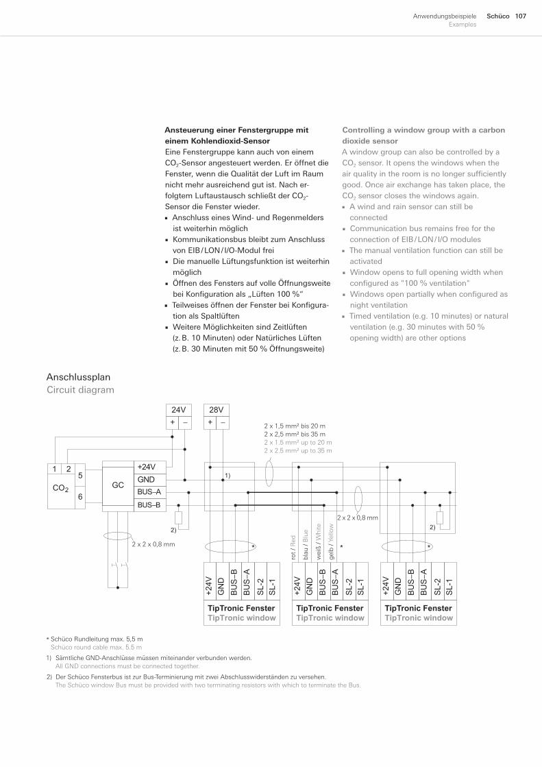
107SchücoAnwendungsbeispieleExamples
Ansteuerung einer Fenstergruppe mit einem Kohlendioxid-SensorEineFenstergruppekannauchvoneinemCO2-Sensorangesteuertwerden.EröffnetdieFenster,wenndieQualitätderLuftimRaumnichtmehrausreichendgutist.Nacher-folgtemLuftaustauschschließtderCO2-SensordieFensterwieder.
AnschlusseinesWind-undRegenmeldersistweiterhinmöglichKommunikationsbusbleibtzumAnschlussvonEIB/LON/I/O-ModulfreiDiemanuelleLüftungsfunktionistweiterhinmöglichÖffnendesFenstersaufvolleÖffnungsweitebei Konfiguration als „Lüften 100 %“Teilweises öffnen der Fenster bei Konfigura-tionalsSpaltlüftenWeitereMöglichkeitensindZeitlüften(z.B.10Minuten)oderNatürlichesLüften(z.B.30Minutenmit50%Öffnungsweite)
■
■
■
■
■
■
AnschlussplanCircuitdiagram
BU
S−A
BU
S−B
GN
D +
24V
SL-
2 S
L-1
BU
S−A
BU
S−B
GN
D +
24V
SL-
2 S
L-1
BU
S−A
BU
S−B
GN
D +
24V
SL-
2 S
L-1
BUS−B
BUS−AGND+24V
+ −
28V+ −
24V
GC
2)
* *
TipTronic FensterTipTronic window
TipTronic FensterTipTronic window
TipTronic FensterTipTronic window
*
1)
2)
CO2
215
6
2x1,5mm²bis20m2x2,5mm²bis35m2x1.5mm²upto20m2x2.5mm²upto35m
gel
b/Y
ello
w
rot
/ Red
wei
ß/
Whi
te
blau
/ B
lue
2x2x0,8mm
2x2x0,8mm
SchücoRundleitungmax.5,5mSchücoroundcablemax.5.5m
*
1) SämtlicheGND-Anschlüssemüssenmiteinanderverbundenwerden. AllGNDconnectionsmustbeconnectedtogether.
2) DerSchücoFensterbusistzurBus-TerminierungmitzweiAbschlusswiderständenzuversehen. TheSchücowindowBusmustbeprovidedwithtwoterminatingresistorswithwhichtoterminatetheBus.
Controlling a window group with a carbon dioxide sensorAwindowgroupcanalsobecontrolledbyaCO2sensor.Itopensthewindowswhentheair quality in the room is no longer sufficiently good.Onceairexchangehastakenplace,theCO2sensorclosesthewindowsagain.
AwindandrainsensorcanstillbeconnectedCommunicationbusremainsfreefortheconnectionofEIB/LON/I/OmodulesThemanualventilationfunctioncanstillbeactivatedWindowopenstofullopeningwidthwhenconfigured as "100 % ventilation"Windows open partially when configured as nightventilationTimedventilation(e.g.10minutes)ornaturalventilation(e.g.30minuteswith50%openingwidth)areotheroptions
■
■
■
■
■
■
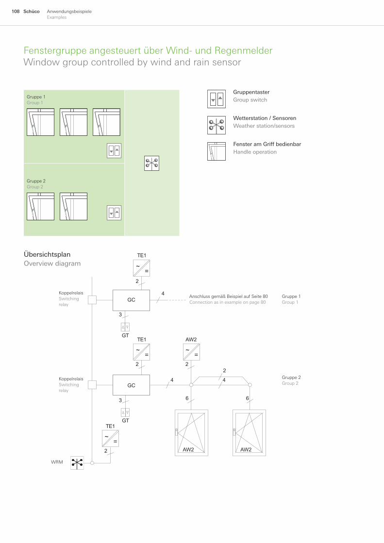
108 Schüco AnwendungsbeispieleExamples
FenstergruppeangesteuertüberWind-undRegenmelderWindowgroupcontrolledbywindandrainsensor
Gruppe1Group1
GC
GC
AW2
AW2 AW2
2
4
3
2
4
22
4
3 66
GT
GT
TE1
TE1
2
TE1
~=
~=
~=
~=
ÜbersichtsplanOverviewdiagram
Gruppe2Group2
AnschlussgemäßBeispielaufSeite80Connectionasinexampleonpage80
KoppelrelaisSwitchingrelay
KoppelrelaisSwitchingrelay
WRM
Wetterstation/SensorenWeatherstation/sensors
GruppentasterGroupswitch
FensteramGriffbedienbarHandleoperation
Gruppe1Group1
Gruppe2Group2
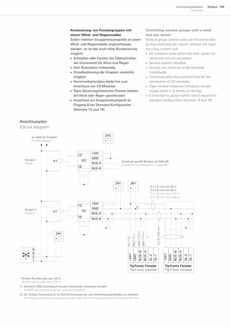
109SchücoAnwendungsbeispieleExamples
Ansteuerung von Fenstergruppen mit einem Wind- und RegenmelderSollenmehrereGruppensteuergeräteaneinenWind-undRegenmelderangeschlossenwerden,soistdasauchohneBussteuerungmöglich
SchließenallerFensterbeiÜberschreitenderGrenzwertefürWindundRegenKeinBussystemnotwendigEinzelbedienungderGruppenweiterhinmöglichKommunikationsbusbleibtfreizumAnschlussvonI/O-ModulenKlareSteuerungshierarchie(FensterbleibenbeiWindoderRegengeschlossen)AnschlussamGruppensteuergerätanEingang B bei Standard Konfiguration (Klemme13und16)
■
■■
■
■
■
AnschlussplanCircuitdiagram
1) SämtlicheGND-Anschlüssemüssenmiteinanderverbundenwerden. AllGNDconnectionsmustbeconnectedtogether.
2) DerSchücoFensterbusistzurBus-TerminierungmitzweiAbschlusswiderständenzuversehen. TheSchücowindowbusmustbeprovidedwithtwoterminatingresistorstoterminatethebus.
SchücoRundleitungmax.5,5mSchücoroundcablemax.5.5m
*
BUS−B
BUS−AGND+24V
GC
+ −
24V
BUS−B
BUS−AGND+24V
GC
+ −
24V+ −
28V
BU
S−A
BU
S−B
GN
D +
24V
SL-
2 S
L-1
TipTronic FensterTipTronic window
BU
S−A
BU
S−B
GN
D +
24V
SL-
2 S
L-1
1)
2)
**
2)
TipTronic FensterTipTronic window
+ −
24V
SA
12
13
16
13
16
K1
K1
2x1,5mm²bis20m2x2,5mm²bis35m2x1.5mm²upto20m2x2.5mm²upto35m
gel
b/Y
ello
w
rot
/ Red
wei
ß/
Whi
te
blau
/ B
lue
2x
2x
0,8
mm
zuweiterenGruppenToothergroups
Gruppe1Group1
Gruppe2Group2
AnschlussgemäßBeispielaufSeite80Connectionasinexampleonpage80
Controlling window groups with a wind and rain sensorSeveralgroupcontrolunitscanbeconnectedtoonewindandrainsensorwithouttheneedforabuscontrolunit
AllwindowsclosewhenthelimitvaluesforwindandrainareexceededNobussystemrequiredGroupscancontinuetobeoperatedindividuallyCommunicationbusremainsfreefortheconnectionofI/Omodules.Clearcontrolhierarchy(windowsremainclosedwhenitiswindyorraining)ConnectiontogroupcontrolunittoinputBforstandard configuration (terminal 13 and 16)
■
■■
■
■
■
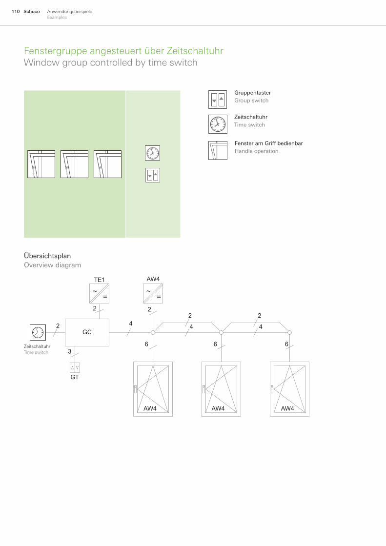
110 Schüco AnwendungsbeispieleExamples
FenstergruppeangesteuertüberZeitschaltuhrWindowgroupcontrolledbytimeswitch
ÜbersichtsplanOverviewdiagram
GC
AW4
AW4 AW4 AW4
4
3
2
4
66
2
4
6
GT
TE1
2
22
~=
~=
ZeitschaltuhrTimeswitch
GruppentasterGroupswitch
ZeitschaltuhrTimeswitch
FensteramGriffbedienbarHandleoperation
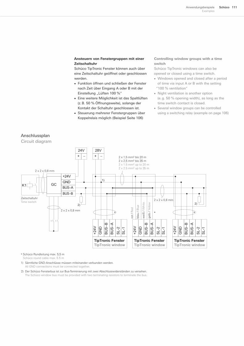
111SchücoAnwendungsbeispieleExamples
Ansteuern von Fenstergruppen mit einer ZeitschaltuhrSchücoTipTronicFensterkönnenauchübereineZeitschaltuhrgeöffnetodergeschlossenwerden.
FunktionöffnenundschließenderFensternachZeitüberEingangAoderBmitderEinstellung„Lüften100%“EineweitereMöglichkeitistdasSpaltlüften(z.B.50%Öffnungsweite),solangederKontaktderSchaltuhrgeschlossenist.SteuerungmehrererFenstergruppenüberKoppelrelaismöglich(BeispielSeite106)
■
■
■
AnschlussplanCircuitdiagram
BU
S−A
BU
S−B
GN
D +
24V
SL-
2 S
L-1
BU
S−A
BU
S−B
GN
D +
24V
SL-
2 S
L-1
BU
S−A
BU
S−B
GN
D +
24V
SL-
2 S
L-1
BUS−B
BUS−AGND+24V
+ −
28V+ −
24V
GC
2)
* *
TipTronic FensterTipTronic window
TipTronic FensterTipTronic window
TipTronic FensterTipTronic window
*
1)
2)
K1
1) SämtlicheGND-Anschlüssemüssenmiteinanderverbundenwerden. AllGNDconnectionsmustbeconnectedtogether.
2) DerSchücoFensterbusistzurBus-TerminierungmitzweiAbschlusswiderständenzuversehen. TheSchücowindowbusmustbeprovidedwithtwoterminatingresistorstoterminatethebus.
SchücoRundleitungmax.5,5mSchücoroundcablemax.5.5m
*
2x1,5mm²bis20m2x2,5mm²bis35m2x1.5mm²upto20m2x2.5mm²upto35m
gel
b/Y
ello
w
rot
/Red
wei
ß/
Whi
te
blau
/ B
lue
2x2x0,8mm
2x2x0,8mm
2x2x0,8mm
ZeitschaltuhrTimeswitch
Controlling window groups with a time switchSchücoTipTronicwindowscanalsobeopenedorclosedusingatimeswitch.
WindowsopenedandclosedafteraperiodoftimeviainputAorBwiththesetting
“100%ventilation”Nightventilationisanotheroption(e.g.50%openingwidth),aslongasthetimeswitchcontactisclosed.Severalwindowgroupscanbecontrolledusingaswitchingrelay(exampleonpage106)
■
■
■

112 Schüco AnwendungsbeispieleExamples
AbkürzungenAbbreviations
AP AufputzmontageSurfacemounting
AC WechselspannungAlternatingcurrent
AW AnschlusswertConnectedload
BC EIBBuskopplerEIBbuscoupler
DC GleichspannungDirectcurrent
EIB EuropäischerInstallationsbusEuropeaninstallationbus
EMA EinbruchmeldeanlageBurglaralarm
ET EinzeltasterIndividualswitch
TE1 HilfsnetzteilAuxiliarypowerpack
FE FunkempfängerRadioreceiver
FB SchücoFensterbusSchücowindowbus
GC GruppensteuergerätGroupcontrolunit
GT GruppentasterGroupswitch
I/O I/O-ModulI/Omodule
K1 KoppelrelaismitDC24VSpulenspannungSwitchingrelaywith24VDCspoolvoltage
K2 KoppelrelaismitSchaltspannungAC250VSwitchingrelaywith250VACswitchingvoltage
KB KommunikationsbusCommunicationsbus
LON LocalOperatingNetworkLocalOperatingNetwork
MS Magnetschalter(optional)Magneticswitch(optional)
MSG MotorsteuergerätMotorcontroldevice
NT NetzteilPowerpack
OL OberlichtToplight
SELV SafetyExtraLowVoltageSafetyExtraLowVoltage
SK SicherheitsklasseSecurityclass
WRM Wind-undRegenmelderWindandrainsensor

113SchücoAnwendungsbeispieleExamples
114 Schüco LeitungsdimensionierungCabledimensioning
Leitungsdimensionierung Cable dimensioning

115SchücoLeitungsdimensionierungCabledimensioning
116
119
LeitungslängenCable length
Anweisungen zur bauseitigen ElektroinstallationInstructions for on-site electrical installation
~=
AW 2
AW 2
~=
Nutzen Sie die Möglichkeit der Netzteilauswahl und Leitungslängendimen-sionierung zur Kostenreduzierung
Use our power pack selection and cable dimensioning options to help you reduce costs

116 Schüco LeitungsdimensionierungCabledimensioning
LeitungslängenCablelengths
Beispiel: Example:
~=
45 m
AW 2
AW 2
1.5 mm2
X m
1.0 mm2230 V ~
Bauseits sind 45 m Zuleitung (1,5 mm² Querschnitt) vom Netzteil zur Abzweigung vorgegeben. Wie groß ist die maximale Länge X der Rundleitung (1,0 mm²) zum Leitungs-übergang des Fensters?
Auf der Kurve (1,5 mm²) entlang fahren, bis 45 m Leitungslänge erreicht sindHorizontal verfahren, bis die Kurve für 1,0 mm² erreicht istAuf dieser Kurve entlang fahren, bis der max. zulässige Spannungsabfall von 4 V erreicht wirdDie Länge X beträgt 10 m
■
■
■
■
Sp
ann
un
gsa
bfa
ll U
in V
/ V
olt
age
dro
p
U in
V
nic
ht
zulä
ssig
N
ot
per
mit
ted
zu
läss
ig
Per
mit
ted
Leitungslänge L in m / Cable length L in m
1,0 mm2
6
5
4
3
2
1
05 10 15 20 25 30 35 40 45 50 55 60
1
2
3 1,5 mm2
2,5 mm2
1,0 mm
2
Mit dem nachfolgenden Diagrammen lässt sich die maximal zu verwendende Leitungs-länge in Abhängigkeit des Leitungsquer-schnittes A für Fenster mit AW2, AW3 und AW4 bestimmen.
Bestimmung der maximalen Leitungslänge AW2 Calculation of maximum cable length AW2
Spannungsabfall U bei konstanter Temperatur T = 50 °C in Abhängigkeit der Leitungslänge Voltage drop U at constant temperature T = 50 °C based on cable length
Using the following diagram, the maximum cable lengths can be calculated for AW1, AW2 and AW4 windows based on the cable cross section A.
45 m of cable (1.5 mm² cross section) from the power pack to the junction are to be provided by the customer. What is the maximum length X of the round cable (1.0 mm²) to the cable link connector for the window?
Move along the curve (1.5 mm²) until 45 m cable length is reachedMove horizontally to reach the 1.0 mm² curveMove along this curve until the maximum permitted voltage drop of 4 V is reachedThe length X is 10 m
■
■
■
■

117SchücoLeitungsdimensionierungCabledimensioning
LeitungslängenCablelengths
Bauseits sind 6 m Rundleitung (1,0 mm² Querschnitt) vom Fenster zur Abzweigung vor-gegeben. Wie groß ist die maximale Länge X der Zuleitung (1,5 mm²) vom Netzteil zur Abzweigdose?
Auf der Kurve (1,0 mm²), ausgehend vom maximal zulässigen Spannungsabfall von 4 V, entlang fahren bis 6 m Leitungslänge erreicht sindHorizontal verfahren bis die Kurve (1,5 mm²) erreicht istAuf dieser Kurve bis zum Koordinaten-ursprung entlang fahrenDie maximale Länge X der Zuleitung beträgt 30 m
■
■
■
■
Bestimmung der maximalen Leitungslänge AW3 Calculation of maximum cable length AW3
Spannungsabfall U bei konstanter Temperatur T = 50°C in Abhängigkeit der Leitungslänge Voltage drop U at constant temperature T = 50 °C based on cable length
Beispiel: Example:
~=
X m
AW 4
AW 3
1.5 mm2
6 m
1.0 mm2230 V ~
Sp
ann
un
gsa
bfa
ll U
in V
/ V
olt
age
dro
p
U in
V
nic
ht
zulä
ssig
N
ot
per
mit
ted
zu
läss
ig
Per
mit
ted
Leitungslänge L in m / Cable length L in m
30
6
5
4
3
2
1
05 10 15 20 25 30 35 40 45 50 55 60
1
2
3
1,5 mm2
2,5 mm2
1,0 m
m2
6 m of round cable (1.0 mm² cross section) from the window to the junction are to be provided by the customer. What is the maximum length X of the feed (1.5 mm²) from the power pack to the junction box?
Move along the curve (1.0 mm²), starting from the maximum permitted voltage drop of 4 V, until 6 m cable length is reachedMove horizontally to reach the 1.5 mm² curveMove along this curve to the originThe maximum length X of the feed is 30 m
■
■
■■
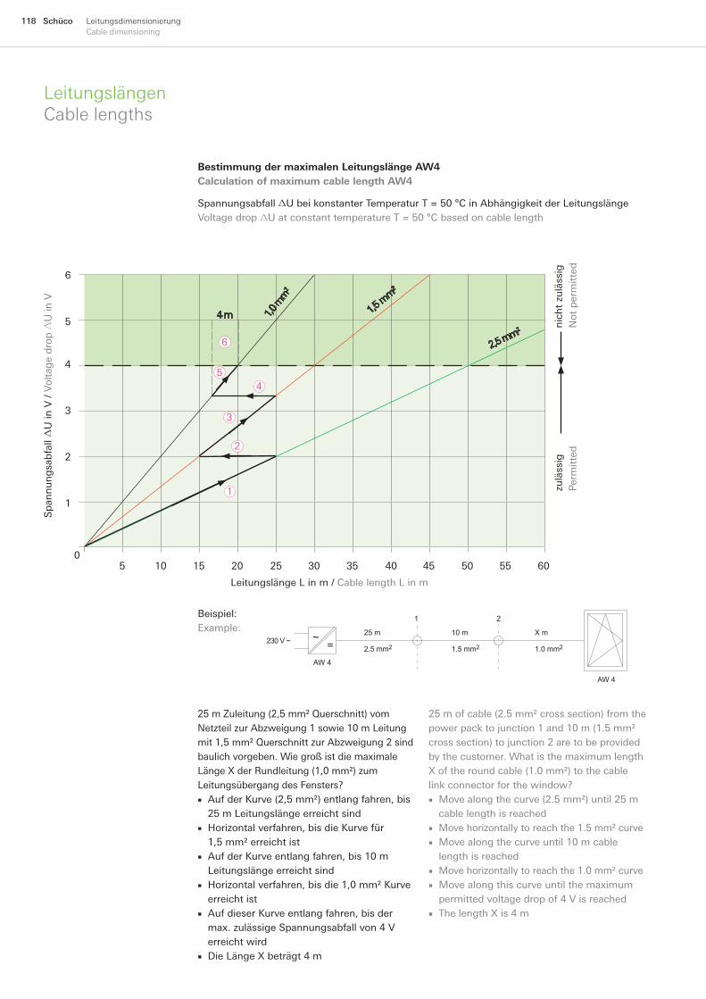
118 Schüco LeitungsdimensionierungCabledimensioning
LeitungslängenCablelengths
25 m Zuleitung (2,5 mm² Querschnitt) vom Netzteil zur Abzweigung 1 sowie 10 m Leitung mit 1,5 mm² Querschnitt zur Abzweigung 2 sind baulich vorgeben. Wie groß ist die maximale Länge X der Rundleitung (1,0 mm²) zum Leitungsübergang des Fensters?
Auf der Kurve (2,5 mm²) entlang fahren, bis 25 m Leitungslänge erreicht sindHorizontal verfahren, bis die Kurve für 1,5 mm² erreicht istAuf der Kurve entlang fahren, bis 10 m Leitungslänge erreicht sindHorizontal verfahren, bis die 1,0 mm² Kurve erreicht istAuf dieser Kurve entlang fahren, bis der max. zulässige Spannungsabfall von 4 V erreicht wirdDie Länge X beträgt 4 m
■
■
■
■
■
■
Bestimmung der maximalen Leitungslänge AW4 Calculation of maximum cable length AW4
Spannungsabfall U bei konstanter Temperatur T = 50 °C in Abhängigkeit der Leitungslänge Voltage drop U at constant temperature T = 50 °C based on cable length
Beispiel: Example:
~=
10 m
AW 4
AW 4
1.5 mm2
X m
1.0 mm2
25 m
2.5 mm2
21
230 V ~
Sp
ann
un
gsa
bfa
ll U
in V
/ V
olt
age
dro
p
U in
V
nic
ht
zulä
ssig
N
ot
per
mit
ted
zu
läss
ig
Per
mit
ted
Leitungslänge L in m / Cable length L in m
6
5
4
3
2
1
05 10 15 20 25 30 35 40 45 50 55 60
1
2
3
1,5 m
m2
2,5 mm2
1,0 m
m2
45
6
4 m
25 m of cable (2.5 mm² cross section) from the power pack to junction 1 and 10 m (1.5 mm² cross section) to junction 2 are to be provided by the customer. What is the maximum length X of the round cable (1.0 mm²) to the cable link connector for the window?
Move along the curve (2.5 mm²) until 25 m cable length is reachedMove horizontally to reach the 1.5 mm² curveMove along the curve until 10 m cable length is reachedMove horizontally to reach the 1.0 mm² curveMove along this curve until the maximum permitted voltage drop of 4 V is reachedThe length X is 4 m
■
■■
■■
■

119SchücoLeitungsdimensionierungCabledimensioning
AnweisungenzurbauseitigenElektroinstallationInstructionsforon-siteelectricalinstallation
Die Verdrahtung des Schüco Fensterbusses (FB) darf nur in einer Linie ausgeführt werden (nicht sternförmig). Am Anfang und am Ende muss je ein Busabschlusswiderstand (120 Ohm) angeschlossen werden. Die max. Länge der Busleitung (2 x 2 x 0,8 mm) beträgt 300 m.
Anweisung Nr. 2
Anweisung Nr. 1
Der Leitungsquerschnitt für die Stromversor-gung der Schüco TipTronic Fenster muss ausreichend dimensioniert werden (z. B. NYM). Die max. zulässigen Leitungslängen dürfen nicht überschritten werden.
Die Massenpotenziale (GND) der Versorgungs-netztteile (DC 28V) und der Steuerungsnetz-teile (DC 24V) müssen einmal untereinander verbunden werden.
Anweisung Nr. 4
Die Leitungslänge zwischen dem Schüco TipTronic Fenster und der bauseitigen Abzweig-dose beträgt max. 5,5 m. Die flexible Rundlei-tung muss zur Abzweigdose in einem Leerrohr (z. B. M20) verlegt werden.
Anweisung Nr. 3
Anweisung Nr. 5
Anweisung Nr. 6
The wiring for the Schüco window bus (FB) must have a linear structure (not star topology). A bus terminating resistor (120 ohm) must be connected at the beginning and at the end. The maximum length of the bus cable (2 x 2 x 0.8 mm) must not exceed 300 m.
The earth potential (GND) of the power packs (DC 28V) and the control powers packs (DC 24V) must be connected to each other once.
The cable length between the Schüco TipTronic window and the junction box on site must be a maximum of 5.5 m. The flexible round cable must be laid in a conduit (e. g. M20) to the junction box.
The individual brown and green wires of the black 6-core round cable must not be cut or connected by the customer. These are reserve wires and must be isolated.
Power packs, bus couplers and group control units must only be installed in a suitable distributor and must only be installed and operated by a qualified electrician. Electrical installation on-site must only be carried out by a qualified electrician.
Instruction No. 6
Instruction No. 5
Instruction No. 4
Instruction No. 3
Instruction No. 2
Netzteile, Buskoppler und Gruppensteuerge-räte dürfen nur in einem geeigneten Elektro-verteiler eingebaut und nur von einer Elektro-fachkraft installiert und in Betrieb genommen werden. Die bauseitige Elektroinstallation ist nur von Elektro-Fachpersonal auszuführen.
Die braune und grüne Einzelader der schwarzen 6-adrigen Rundleitung dürfen bauseits nicht abgeschnitten und auch nicht angeschlossen werden. Diese dienen als Reserveadern und sind isoliert zu verlegen.
The cable cross section for the power supply to Schüco TipTronic windows must be of sufficient dimension (e. g. NYM). The maximum permissible cable lengths must not be exceeded.
Instruction No. 1
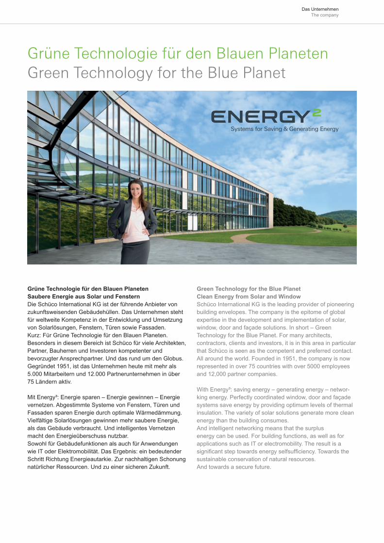
Das Unternehmen The company
Green Technology for the Blue PlanetClean Energy from Solar and WindowSchüco International KG is the leading provider of pioneering building envelopes. The company is the epitome of global expertise in the development and implementation of solar, window, door and façade solutions. In short – Green Technology for the Blue Planet. For many architects, contractors, clients and investors, it is in this area in particular that Schüco is seen as the competent and preferred contact. All around the world. Founded in 1951, the company is now represented in over 75 countries with over 5000 employees and 12,000 partner companies.
With Energy³: saving energy – generating energy – networ-king energy. Perfectly coordinated window, door and façade systems save energy by providing optimum levels of thermal insulation. The variety of solar solutions generate more clean energy than the building consumes. And intelligent networking means that the surplus energy can be used. For building functions, as well as for applications such as IT or electromobility. The result is a signifi cant step towards energy selfsuffi ciency. Towards the sustainable conservation of natural resources. And towards a secure future.
Grüne Technologie für den Blauen PlanetenSaubere Energie aus Solar und FensternDie Schüco International KG ist der führende Anbieter von zukunftsweisenden Gebäudehüllen. Das Unternehmen steht für weltweite Kompetenz in der Entwicklung und Umsetzung von Solarlösungen, Fenstern, Türen sowie Fassaden. Kurz: Für Grüne Technologie für den Blauen Planeten.Besonders in diesem Bereich ist Schüco für viele Architekten, Partner, Bauherren und Investoren kompetenter und bevorzugter Ansprechpartner. Und das rund um den Globus. Gegründet 1951, ist das Unternehmen heute mit mehr als 5.000 Mitarbeitern und 12.000 Partnerunternehmen in über 75 Ländern aktiv.
Mit Energy³: Energie sparen – Energie gewinnen – Energie vernetzen. Abgestimmte Systeme von Fenstern, Türen und Fassaden sparen Energie durch optimale Wärmedämmung. Vielfältige Solarlösungen gewinnen mehr saubere Energie, als das Gebäude verbraucht. Und intelligentes Vernetzen macht den Energieüberschuss nutzbar. Sowohl für Gebäudefunktionen als auch für Anwendungen wie IT oder Elektromobilität. Das Ergebnis: ein bedeutender Schritt Richtung Energieautarkie. Zur nachhaltigen Schonung natürlicher Ressourcen. Und zu einer sicheren Zukunft.
Grüne Technologie für den Blauen PlanetenGreen Technology for the Blue Planet
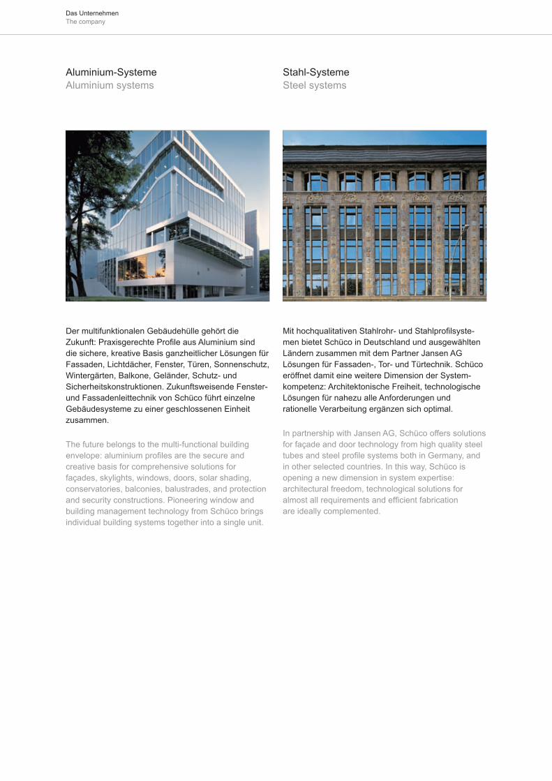
Das Unternehmen The company
Der multifunktionalen Gebäudehülle gehört die Zukunft: Praxisgerechte Profile aus Aluminium sind die sichere, kreative Basis ganzheitlicher Lösungen für Fassaden, Lichtdächer, Fenster, Türen, Sonnenschutz, Wintergärten, Balkone, Geländer, Schutz- und Sicherheitskonstruktionen. Zukunftsweisende Fenster- und Fassadenleittechnik von Schüco führt einzelne Gebäudesysteme zu einer geschlossenen Einheit zusammen.
The future belongs to the multi-functional building envelope: aluminium profiles are the secure and creative basis for comprehensive solutions for façades, skylights, windows, doors, solar shading, conservatories, balconies, balustrades, and protection and security constructions. Pioneering window and building management technology from Schüco brings individual building systems together into a single unit.
Mit hochqualitativen Stahlrohr- und Stahlprofilsyste-men bietet Schüco in Deutschland und ausgewählten Ländern zusammen mit dem Partner Jansen AG Lösungen für Fassaden-, Tor- und Türtechnik. Schüco eröffnet damit eine weitere Dimension der System- kompetenz: Architektonische Freiheit, technologische Lösungen für nahezu alle Anforderungen und rationelle Verarbeitung ergänzen sich optimal.
In partnership with Jansen AG, Schüco offers solutions for façade and door technology from high quality steel tubes and steel profile systems both in Germany, and in other selected countries. In this way, Schüco is opening a new dimension in system expertise: architectural freedom, technological solutions for almost all requirements and efficient fabrication are ideally complemented.
Aluminium-SystemeAluminium systems
Stahl-Systeme Steel systems
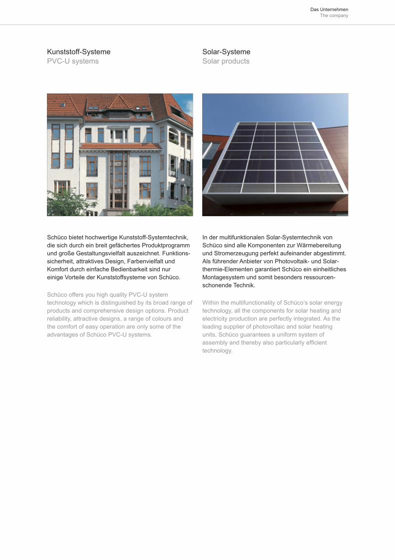
Das Unternehmen The company
Schüco bietet hochwertige Kunststoff-Systemtechnik, die sich durch ein breit gefächertes Produktprogramm und große Gestaltungsvielfalt auszeichnet. Funktions-sicherheit, attraktives Design, Farbenvielfalt und Komfort durch einfache Bedienbarkeit sind nur einige Vorteile der Kunststoffsysteme von Schüco.
Schüco offers you high quality PVC-U system technology which is distinguished by its broad range of products and comprehensive design options. Product reliability, attractive designs, a range of colours and the comfort of easy operation are only some of the advantages of Schüco PVC-U systems.
In der multifunktionalen Solar-Systemtechnik von Schüco sind alle Komponenten zur Wärmebereitung und Stromerzeugung perfekt aufeinander abgestimmt. Als führender Anbieter von Photovoltaik- und Solar-thermie-Elementen garantiert Schüco ein einheitliches Montagesystem und somit besonders ressourcen-schonende Technik.
Within the multifunctionality of Schüco’s solar energy technology, all the components for solar heating and electricity production are perfectly integrated. As the leading supplier of photovoltaic and solar heating units, Schüco guarantees a uniform system of assembly and thereby also particularly efficient technology.
Kunststoff-Systeme PVC-U systems
Solar-Systeme Solar products
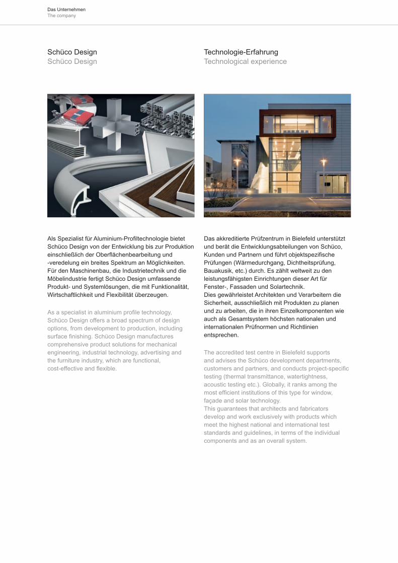
Das Unternehmen The company
Als Spezialist für Aluminium-Profiltechnologie bietet Schüco Design von der Entwicklung bis zur Produktion einschließlich der Oberflächenbearbeitung und -veredelung ein breites Spektrum an Möglichkeiten. Für den Maschinenbau, die Industrietechnik und die Möbelindustrie fertigt Schüco Design umfassende Produkt- und Systemlösungen, die mit Funktionalität, Wirtschaftlichkeit und Flexibilität überzeugen.
As a specialist in aluminium profile technology, Schüco Design offers a broad spectrum of design options, from development to production, including surface finishing. Schüco Design manufactures comprehensive product solutions for mechanical engineering, industrial technology, advertising and the furniture industry, which are functional, cost-effective and flexible.
Schüco Design Schüco Design
Technologie-Erfahrung Technological experience
Das akkreditierte Prüfzentrum in Bielefeld unterstützt und berät die Entwicklungsabteilungen von Schüco, Kunden und Partnern und führt objektspezifische Prüfungen (Wärmedurchgang, Dichtheitsprüfung, Bauakusik, etc.) durch. Es zählt weltweit zu den leistungsfähigsten Einrichtungen dieser Art für Fenster-, Fassaden und Solartechnik. Dies gewährleistet Architekten und Verarbeitern die Sicherheit, ausschließlich mit Produkten zu planen und zu arbeiten, die in ihren Einzelkomponenten wie auch als Gesamtsystem höchsten nationalen und internationalen Prüfnormen und Richtlinien entsprechen.
The accredited test centre in Bielefeld supports and advises the Schüco development departments, customers and partners, and conducts project-specific testing (thermal transmittance, watertightness, acoustic testing etc.). Globally, it ranks among the most efficient institutions of this type for window, façade and solar technology. This guarantees that architects and fabricators develop and work exclusively with products which meet the highest national and international test standards and guidelines, in terms of the individual components and as an overall system.
Das Unternehmen The company
Aluminium ist... Aluminium is...
der Bauwerkstoff der Zukunft, da im hohen Maße wertbeständig. Nur Aluminium bietet der Architektur die Gestaltungsvielfalt in Form und Farbe.
langlebig und wertbeständig, da es weder korrodiert noch verrottet. Bauelemente bleiben ein Leben lang ohne erhaltende Maßnahmen für die Oberfläche schön wie am ersten Tag.
pflegeleicht, wird eloxiert oder farbbeschichtet eingesetzt. Außer Reinigen fällt keine Wartung an.
beliebig gestaltbar, und läßt sich mit einem hohen Vorfertigungsgrad für Bauprofile verformen. Diese sind praktisch in jeder Form herstellbar.
designorientiert, also der ideale Werkstoff zum Einsatz in zeitgemäße Architektur. Alle Formen und Farben sind machbar.
nicht brennbar, es wird sogar in Verbindung mit energieverzehrenden Materialien zu Feuerschutz-türen T90 verarbeitet.
wärmedämmend, Aluminium-Profile für Fenster, Türen und Fassaden sind zweischalig und mit Wärmedämmstegen verbunden.
energiesparend, Aluminium kann unendlich oft mit geringem Energieverbrauch eingeschmolzen werden. Je öfter Aluminium recycelt wird, um so wirtschaftlicher ist es.
leicht und stabil, mit einem spezifischen Gewicht von nur 2,7 g/cm³ sehr leicht. Daher werden gerade am Bau Rohbaukosten gespart. Die Festigkeit ist sehr hoch und präzise zu berechnen – also ideal für großflächige Fenster, Türen und Fassaden.
sicher, und bedingt durch hohe Festigkeit in Verbindung mit Spezialbeschlägen besonders einbruchhemmend.
umweltverträglich, und in keiner Weise schädlich für die Umwelt. Auch im Brandfall entstehen keine umweltschädigenden Stoffe.
■
■
■
■
■
■
■
■
■
■
■
the building material of the future, as it maintains its value. Only aluminium can give architecture such a variety of combinations in form and colour.
durable and stable, as it neither corrodes nor rots. Building components last a lifetime without the need for further surface treatment. It stays as good as new.
easy to maintain, as it is anodised or colour-coated. With the exception of cleaning, no maintenance is necessary.
versatile, and can be fabricated into preformed assemblies. These can be produced in practically any shape.
a material for design, ideal for use in contemporary architecture. All kinds of shapes and colours can be produced.
non-flammable, used together with energy-absorbing materials to produce T90 fire doors.
thermal insulation, aluminium profiles for windows, doors and façades are double-chambered and rolled together with insulating bars.
energy efficient, aluminium can be melted down repeatedly, expending the minimum amount of energy. Aluminium becomes more economical each time it is recycled.
light and stable, with a specific gravity of only 2.7 g/cm³. Savings can therefore be made on the cost of the building shell. It has a high degree of stability which can be calculated with precision, making it ideal for large area windows, doors and façades.
secure, and particularly burglar-resistant both because of its strength and when used with special fittings.
ecologically harmless, and does not damage the environment. Even during fires, no environmental pollutants are released.
■
■
■
■
■
■
■
■
■
■
■
Das Unternehmen The company
Für Sie und die Umwelt ein Gewinn: Schüco-Systeme aus Aluminium
Aluminium ist leicht, fest, pflegeleicht und korrosionsbeständig – ein Werkstoff mit langer Lebensdauer.
Aluminium ist präzise formbar – für energiesparende Bauteile mit hoher Dichtigkeit, Schall- und Wärmedämmung.
Von dem Mineral Bauxit, aus dem Aluminium gewonnen wird, verfügt die Erde über nahezu unerschöpfliche Vorkommen.
Der Energiebedarf zur Gewinnung von Aluminium wird weltweit zu über 60 % aus umweltfreundlicher und immer wieder verfügbarer Wasserkraft gedeckt.
Alt-Aluminium wird schon immer recycelt und behält im Wertstoff-Kreislauf seine orginalen Qualitätseigenschaften.
Beim Einschmelzen von Alt-Aluminium sind nur noch 5 % des ursprünglichen Energieeinsatzes erforder-lich.
Bereits heute bestehen rund 35 % des Aluminium-Verbrauchs aus wiederverwertetem Aluminium. Der Anteil wächst ständig.
Im Baubereich existiert ein umfassendes Wertstoff-Kreislauf-System.
■
■
■
■
■
■
■
A success for you and the environment: Schüco aluminium systems
Aluminium is light, solid and non-corrosive – a maintenance-free, long life material.
Aluminium can be shaped with precision to make energy-saving building components, sealed against the elements and with a high degree of sound and thermal insulation.
The mineral bauxite, from which aluminium is extracted, is present in the earth in almost inexhaustible quantities.
Over 60 % of the energy required to extract aluminium worldwide is generated from environmentally friendly, renewable sources, namely water power.
After aluminium has been recycled, it still retains its quality characteristics.
When aluminium is melted down for recycling, only 5 % of the original energy input is required.
35 % of aluminium consumption today already consists of recycled aluminium. This percentage is steadily increasing.
Comprehensive resource recycling plays an important role within the building industry.
■
■
■
■
■
■
■
An organisation serving the environment
Materials recycling
Aluminium and environement in window and façade construction
Eine Gesellschaft im Dienst der Umwelt
Wertstoffkreislauf
Aluminium und Umwelt im Fenster- und Fassadenbau
Zuschnittreste aus den Betrieben und ausgebaute Alt-Bauteile werden der Wiederverwendung zugeführt. Schüco International und seine Partner fördern und nutzen diesen Kreislauf seit Jahren.
Factory cut-offs and reclaimed materials from the renovation of old buildings are all recycled for future use. For many years, Schüco International and its partners have actively employed and promoted recycling.
Aluminium und Umwelt Aluminium and environment
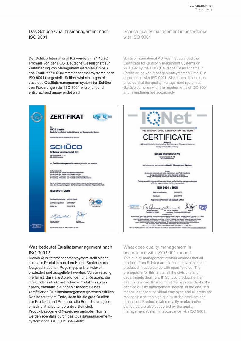
Das Unternehmen The company
Der Schüco International KG wurde am 24.10.92 erstmals von der DQS (Deutsche Gesellschaft zur Zertifizierung von Managementsystemen GmbH) das Zertifikat für Qualitätsmanagementsysteme nach ISO 9001 ausgestellt. Seither wird sichergestellt, dass das Qualitätsmanagementsystem bei Schüco den Forderungen der ISO 9001 entspricht und entsprechend angewendet wird.
Schüco International KG was first awarded the Certificate for Quality Management Systems on 24.10.92 by the DQS (Deutsche Gesellschaft zur Zertifizierung von Managementsystemen GmbH) in accordance with ISO 9001. Since then, it has been ensured that the quality management system at Schüco complies with the requirements of ISO 9001 and is implemented accordingly.
Was bedeutet Qualitätsmanagement nach ISO 9001? Dieses Qualitätsmanagementsystem stellt sicher, dass alle Produkte aus dem Hause Schüco nach festgeschriebenen Regeln geplant, entwickelt, produziert und ausgeliefert werden. Voraussetzung hierfür ist, dass alle Abteilungen und Ressorts, die direkt oder indirekt mit Schüco-Produkten zu tun haben, ebenfalls die hohen Standards eines zertifizierten Qualitätsmanagementsystemes erfüllen. Das bedeutet am Ende, dass für die gute Qualität der Produkte und Prozesse alle Bereiche und jeder einzelne Mitarbeiter verantwortlich sind. Produktbezogene Gütezeichen und/oder Normen werden ebenfalls durch das Qualitätsmanagement-system nach ISO 9001 unterstützt.
What does quality management in accordance with ISO 9001 mean? This quality management system ensures that all products from Schüco are planned, developed and produced in accordance with specific rules. The prerequisite for this is that all the divisions and departments dealing with Schüco products either directly or indirectly also meet the high standards of a certified quality management system. In the end, this means that each individual employee and all areas are responsible for the high quality of the products and processes. Product-related quality marks and/or standards are also supported by the quality management system in accordance with ISO 9001.
Das Schüco Qualitätsmanagement nach ISO 9001
Schüco quality management in accordance with ISO 9001

Das Unternehmen The company
Zusätzlich zu den Katalogen unterstützt Schüco Sie mit:
Kaufmännischer Betreuung durch den Gebiets-manager im AußendienstAusschreibungsberatung beim Planer durch den Fachberater FassadentechnikTechnischer Beratung durch den technischen InnendienstTechnische Schulungen und Methodentrainings durch die Trainingsabteilung Bestellannahme und Abwicklung im VerkaufsinnendienstVeredelung der Profile mit einer reichhaltigen Auswahl an möglichen OberflächenPlanung und Kalkulation durch Schüco Service-Software Optimierung von Fertigung und Montage durch Konzeption, Maschinen und BetriebsmittelZentralen Hotlines für Spezialgebiete (z.B. Mechatronik) Verkaufsförderungsmaterial für Werbung und SchauraumStets aktuelle Informationen im Internet
■
■
■
■
■
■
■
■
■
■
■
In addition to the provision of manuals, Schüco also supports you with:
Commerical support from the Area Sales ManagersAdvice to developers on tendering from Architectural Project Managers
Technical advice from the Technical DepartmentTechnical training and soft skills courses given by the Training Department Ordering and order processing in sales administrationSurface finishing of profiles in a wide range of colours and finishesPlanning and calculation using Schüco Service softwareFabrication and installation optimisation through workshop planning, machinery and operating materialsHotline support for special fields (e.g. mechatronics)Promotional materials for advertising and showroomUp-to-date information on our website
■
■
■
■
■
■
■
■
■
■
■
Katalog: Art.-Nr. 00356 / Ausgabe: Mai 2011 Manual No.: 00356 / Edition: May 2011
Der Inhalt dieses Kataloges ist rechtlich geschützt. Es gelten die Nutzungsbedingungen der Schüco International KG für die Nutzung der Schüco-Kataloge (Kataloglizenz) Nachdruck, auch auszugsweise, nur mit unserer Genehmigung. Wir behalten uns Änderungen, die dem technischen Fortschritt dienen, vor. Alle unsere Systeme und technischen Produkte wurden unter Berücksichtigung deutscher und europäischer Normen, Richtlinien und Empfehlungen entwickelt. Daraus können sich im Einzelfall Abweichungen zu ausländischen Normen, Richtlinien und Empfehlungen ergeben. Ein landesspezifischer Vergleich ist auf jeden Fall von unseren Kunden vorzunehmen. Es gelten unsere jeweils aktuellen Allgemeinen Verkaufs- und Lieferbedingungen - Bestellunterlagen sind nicht als Fertigungsunterlagen anzuwenden. Der Druckstand wird in den Fußzeilen gekennzeichnet mit Monat.Jahr (Beispiel 03.2011). Das Ausgabedatum der Fertigungszeichnungen wird in den Schriftfeldern als Tag.Monat.Jahr angegeben (Beispiel: 31.03.2011).
The contents of this catalogue are protected by law. The Schüco International KG conditions of use apply to the use of Schüco manuals (catalogue licence). Reproduction, even in part, is not permitted, except with our approval. We reserve the right to introduce modifications in the interest of technical progress. All our systems and technical products have been developed with due regard to the rules and conditions of DIN (Deutsches Institut für Normung e.V.). Consequently, deviations from other standards may sometimes arise. Customers should therefore make their own comparison with appropriate standards in their own country. Our general sales and delivery conditions apply. Ordering instructions are not intended for use as fabrication instructions. The print date is indicated in the page footer by Month/Year (e.g. 03.2011). The issue date of the fabrication drawings is indicated in the title box in the bottom right hand corner by Day/Month/Year (e.g. 31.03.2011).
Schüco International KG Karolinenstraße 1-15 • D-33609 Bielefeld Telefon +49 521 783-0 Telefax +49 521 783-451 www.schueco.com

Green Technology for the Blue PlanetClean Energy from Solar and Windows
Grüne Technologie für den Blauen PlanetenSaubere Energie aus Solar und Fenstern
Sch
üco
Tip
Tron
ic –
Sys
tem
hand
buch
Sch
üco
Tip
Tron
ic –
Sys
tem
han
dboo
k
Schüco Tip Tronic – Systemhandbuch Schüco Tip Tronic – System handbook
Nutzungsbedingungen der Schüco International KG für die Nutzung der Schüco-Kataloge (Kataloglizenz)
LizenzbedingungenDurch das Öffnen der Schutzhülle (Plastikfolie) vereinbart der Empfänger („Kunde“) des eingeschweißten Katalogs mit der Schüco International KG („Schüco“) die nachfolgenden Regelungen. Falls der Kunde diese Regelungen nicht anerkennen will, ist der eingeschweißte Katalog unge-öffnet zurückzugeben; eine Nutzung oder Weitergabe desselben ist dann nicht zu lässig. Schüco weist ausdrücklich darauf hin, dass die Abgabe von gedruckten Informationen in Bezug auf die von Schüco vertriebenen Produkte („Kataloge“) ausschließlich nach Abschluss und zu den Be-dingungen dieser Kataloglizenz vereinbarung zwischen dem Empfänger und Schüco erfolgt. Damit gelten zwischen dem die Kataloge und seine Inhalte nutzenden Kunden und Schüco die nachfolgenden Regelungen.Urheber- und NutzungsrechteDie Kataloge und die in ihnen enthaltenen Inhalte und Daten („Katalo-ginhalte“) sind rechtlich geschützt. Alle Rechte an den Kataloginhalten stehen allein Schüco zu.NutzungserlaubnisDer Katalog bleibt im Eigentum von Schüco. Er ist für den Kunden persönlich bestimmt und wird diesem leihweise überlassen. Schüco gestattet dem Kunden widerrufl ich, die Katalog inhalte zum Zwecke der Erleichterung der Arbeit mit, des Bezugs von und der Planung von und mit Schüco-Produkten zu nutzen. Jede Weitergabe des Katalogs bzw. der Katalog inhalte an Dritte sowie jede weitergehende Nutzung oder Verwertung der Kataloginhalte außerhalb der rechtlichen Grenzen – ins-besondere solcher des Urheberrechtsgesetzes, des Gesetzes gegen den unlauteren Wettbewerb und der Bestimmungen dieses Vertrages – ist ohne vorherige schriftliche Zustimmung von Schüco unzulässig. Insbe-sondere die Übernahme bzw. Speicherung der Kataloginhalte (vollständig oder teilweise) in Dateien, elektronische Datenverarbeitungsanlagen und/oder Speichermedien aller Art ist ausdrücklich untersagt. Anwendbares RechtEs gilt deutsches Recht. Für alle Streitigkeiten aus diesem Vertrag ist das Landgericht Bielefeld, Deutschland, zuständig.
Condiciones de utilización Schüco International KG para el empleo del Catálogo-Schüco (Licencia del Catálogo)
Condiciones de la licenciaAl abrir la bolsa protectora (bolsa de plástico) de este Catálogo, el receptor (cliente), se compromete y asume las normas siguientes de Schüco International KG (Schüco). En caso de no querer reconocer el cliente estas normas, tiene que devolverse este Catálogo sin abrir; la utilización o traspaso del mismo queda por tanto prohibido. Schüco in-dica expresamente, que la entrega de información impresa, respecto de los productos vendidos (Catálogos) incluso al término y para el manejo, se realiza la aceptación de concertación de la licencia del Catálogo entre el cliente y Schüco. Por tanto sirven, entre el cliente que utilice el Catálogo y su contenido y Schüco, las normas siguientes.Derechos de autor y de utilizaciónLos Catálogos y los datos contenidos (“Contenido del Catálogo”) están protegidos legalmente. Todos los derechos sobre el contenido del Catá-logo corresponden a Schüco.Permiso de utilizaciónSchüco mantiene el Catálogo en propiedad. El Catálogo es prestado a un cliente determinado. Schüco permite la utilización prescriptible, del contenido de este Catálogo, para facilitar el trabajo, respecto de la planifi cación de y con productos Schüco. Un traslado del Catálogo o su contenido a terceros o la utilización del Catálogo o su contenido fuera de los términos legales – principalmente respecto de los derechos de autor y de utilización, leyes contra la mala competencia y normas de este contrato – no esta, sin permiso escrito de Schüco, permitido. Principalmente queda expresamente prohibido, la obtención o almace-namiento de los datos contenidos en el Catálogo (totales o parciales) en elementos de almacenamiento electrónico y/o por cualquier otro medio. Aplicación de la leySe aplicará el derecho alemán. Para cualquier confl icto con este con-trato es competencia de la Audiencia Provincial de Bielefeld, Alemania.
Schüco International KG Conditions of Use for the use of Schüco manuals (catalogue licence)
Licence conditionsBy opening the protective cover (plastic foil) the recipient (“customer”) of the shrink-wrapped manual agrees with Schüco International KG (“Schüco”) to be bound by the following rules. If the customer is not prepared to accept these conditions, the shrink-wrapped manual must be returned unopened; use or circulation of the manual is then not permitted. Schüco expressly advises that printed information relating to the products sold by Schüco (“manuals”) may be transmitted only following conclusion of the catalogue licence agreement between the recipient and Schüco and on the terms given therein. The following conditions therefore apply between Schüco and the customers using the manuals and their content.Copyright and rights of useThe manuals and the content and data they contain (“catalogue content”) are protected by law. All rights to catalogue content belong exclusively to Schüco.Permission for useThe manual remains the property of Schüco. It is intended for the customer’s personal use and is given to him/her on a loan basis. Schüco gives the customer the right, which may also be revoked, to utilise the contents of the manual to facilitate their work through the use of, procurement of, and planning/design of Schüco products. Any dissemination of the manual or its contents to third parties and any additional usage or exploitation of catalogue content outside of the law – especially copyright law, the law against unfair competition and the regulations of this contract – is not permitted without the prior written consent of Schüco. In particular, the transfer and storage of catalogue content (in full or in part) to fi les, electronic data processing systems and/or storage media of any kind is expressly prohibited. Applicable lawGerman law applies. The district court in Bielefeld, Germany is responsible for all disputes arising from this contract.
Condizioni stabilite dalla Schüco Inter national KG per l’utilizzo dei cataloghi Schüco (Licenza cataloghi)
Condizioni di licenza Con l’apertura dell’involucro protettivo (foglio in plastica) il destinatario
(„cliente“) del catalogo sigillato concorda con Schüco International KG
(„Schüco“) le condizioni sottoindicate. Nel caso il cliente non intenda
riconoscere queste condizioni, il catalogo deve essere restituito sigillato,
non aperto; non è ammesso l’utilizzo e la cessione dello stesso. Schüco
precisa espressamente che la divulgazione delle informazioni pubblicate
in relazione ai prodotti commercializzati da Schüco („cataloghi“) avviene
esclusivamente in seguito ed alle condizioni descritte dal presente
accordo di licenza cataloghi tra l’utilizzatore e Schüco. Sono pertanto
valide tra i clienti utilizzatori del catalogo e del suo contenuto e Schüco
le seguenti condizioni.
Diritti d’autore e d’usoI cataloghi, i dati ed i contenuti presenti al loro interno („contenuti del
catalogo“) sono giuridicamente protetti. Tutti i diritti relativi ai contenuti
dei cataloghi spettano in esclusiva alla Schüco.
Permessi di utilizzoIl catalogo resta di proprietà della Schüco. E’ destinato al cliente
personalmente e viene ad esso ceduto in prestito. Schüco concede al
cliente, salvo revoca, i contenuti del catalogo allo scopo di facilitarne il
lavoro, in riferimento alla progettazione ed all’uso dei prodotti Schüco.
Non è ammessa alcuna cessione a terzi del catalogo o dei contenuti
in esso presenti e qualsiasi altro utilizzo o recupero dei contenuti del
catalogo oltre i limiti stabiliti dalla legge – in particolare in relazione alla
legge sulla protezione dei diritti d’autore, alla legge contro la concorrenza
sleale e alle condizioni del presente contratto – senza previo consenso
scritto da parte di Schüco. In particolare la copia o la memorizzazione
dei contenuti del catalogo (completa o parziale) in archivi, dispositivi
elettronici per l’elaborazione dati e/o apparecchiature per l’archiviazione
di tutti i tipi è espressamente vietata.
Leggi applicabiliSono valide le leggi in vigore in Germania. Nel caso di contro-versia il
foro competente è quello di Bielefeld, Germania.
Conditions, défi nies par Schüco International KG, visant l’utilisation des catalogues Schüco (licence de catalogue)
Conditions de licence En ouvrant l’enveloppe protectrice (fi lm plastique), le destinataire
(ci-après dénommé «client») du catalogue sous fi lm soudé convient
avec la Sté Schüco International KG (ci-après dénommée «Schüco»)
les règlements qui suivent. Si le client ne veut pas reconnaître
ces règlements, il devra restituer le catalogue sous son fi lm soudé
intact; toute utilisation ou communication du catalogue est dans
ce cas illicite. Schüco attire expressément l’attention sur le fait
que la fourniture d’informations imprimées (ci-après dénommées
«catalogues») afférentes aux produits distribués par Schüco a lieu
exclusivement après conclusion, entre le destinataire et Schüco, du
présent accord de licence-catalogue et aux conditions de ce même
accord. De la sorte s’appliquent entre le client utilisant les catalogues
et leurs contenus d’une part, et Schüco d‘autre part, les règlements
suivants.
Droits d’auteur et droits d’utilisation Les catalogues, les contenus et données (ci-après dénommés
«contenus des catalogues») qui y fi gurent sont juridiquement protégés.
Schüco est le propriétaire exclusif de tous les droits protégeant les
contenus des catalogues.Autorisation d‘utilisationSchüco demeure propriétaire du catalogue. Le catalogue est destiné
personnellement au client et ne lui est remis qu’à titre de prêt. Schüco
autorise le client, de façon révocable, à utiliser les contenus du
catalogue dans le but de se faciliter le travail avec les produits Schüco,
de se procurer et de planifi er des produits Schüco et de planifi er des
produits Schüco avec ces mêmes produits. Toute communication du
catalogue ou de ses contenus à des tiers ainsi que toute utilisation ou
exploitation avancée des contenus du catalogue, débordant des limites
juridiques – notamment celles fi xées par la loi sur la protection des
droits d‘auteur, la loi contre la concurrence déloyale et les dispositions
du présent contrat – sont illicites si Schüco n‘a pas au préalable fourni
son consentement écrit. Notamment la reprise ou l’enregistrement
(intégral(e) ou partiel(le)) des contenus de catalogue dans des fi chiers,
des installations de traitement électronique des données et/ou des
médias d’enregistrement de toutes sortes est expressément interdit.
Droit applicableLe droit allemand sera appliqué. Le tribunal de grande instance
de Bielefeld en Allemagne sera le seul compétent en cas de litige
résultant du présent contrat.
Gebruiksvoorwaarden van Schüco Inter national KG voor gebruik van de Schüco catalogi (catalogus licentie)
LicentievoorwaardenWanneer de ontvanger („klant“) de gesealde verpakking (plasticfolie) van de catalogus opent, verklaart de klant zich akkoord met de volgende regels van Schüco International KG („Schüco“). Als de klant niet instemt met deze regels, dient de gesealde catalogus ongeopend te worden geretourneerd. Het is dan niet toegestaan de catalogus te gebruiken of aan derden te verstrekken. Schüco benadrukt dat de verstrekking van gedrukte informatie met betrekking tot handelsproducten van Schüco („catalogi“) uitsluitend plaatsvindt na overeenstemming over en onder de voorwaarden van deze catalogusovereenkomst tussen de ontvanger en Schüco. Daarmee zijn de volgende regels van kracht tussen Schüco en de klant die de catalogi en de inhoud daarvan gebruikt.Auteurs- en gebruiksrechtenDe catalogi en de inhoud en gegevens daarin („catalogusinhoud“) zijn wettelijk beschermd. Schüco behoudt het alleenrecht op de volledige inhoud van de catalogi.Toegestaan gebruikDe catalogus blijft eigendom van Schüco. Deze is bedoeld voor persoonlijk gebruik door de klant en wordt aan de klant in bruikleen gegeven. Schüco geeft de klant herroepelijk toestemming de catalogusinhoud te gebruiken voor het werken met, verkrijgen van en plannen met Schüco-producten. Het verstrekken van de catalogus of de catalogusinhoud aan derden alsmede ieder ander gebruik of ander profi jt van de catalogusinhoud buiten de wettelijke grenzen – in het bijzonder wetten op het gebied van auteursrecht, oneerlijke concurrentie en de bepalingen van deze overeenkomst – is verboden zonder voorafgaande schriftelijke toestemming van Schüco. In het bijzonder het (geheel of gedeeltelijk) overnemen of opslaan van catalogusinhoud in bestanden, elektronische systemen voor gegevensverwerking en/of opslagmedia van welke aard dan ook is verboden. Toepasselijk rechtOp deze voorwaarden is Duits recht van toe passing. Eventuele geschillen voortvloeiende uit of samenhangende met deze voorwaarden, zullen worden voorgelegd aan de arrondissementsrechtbank in Bielefeld, Duitsland.
de
es
en
it
fr
nl
Achtung, vor dem Öffnen bitte lesen! Important: please read before opening Attention, lire ceci avant l‘ouverture! ¡Atención, léase antes de abrir! Attenzione, leggere prima di aprire! Let op! Lees dit vóór het openen!
Art.
No.
003
56/0
5.20
11Än
deru
ngen
vor
beha
lten.
Alle
Abb
ildun
gen
in d
iese
r Bro
schü
re z
eige
nle
digl
ich
Anw
endu
ngsb
eisp
iele
für S
chüc
o Pr
oduk
te.
Subj
et to
cha
nge
with
out n
otic
e. A
ll ill
ustr
atio
ns in
this
bro
chur
e ar
e on
ly
exam
ples
of S
chüc
o pr
oduc
ts.
64890_Umschlag_TipTronic_00356.indd U4-U164890_Umschlag_TipTronic_00356.indd U4-U1 21.04.11 15:3621.04.11 15:36