scan - georgia institute of technology
TRANSCRIPT


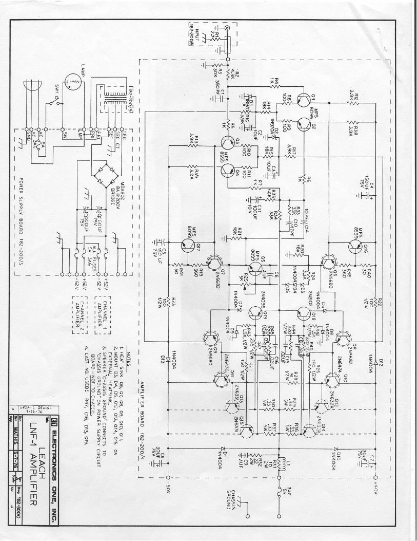

8. Drawing 182 − 100 shows resistors R44 and R45 (both 240Ω, 1/4W) near transistorsQ18 and Q19. These resistors should be replaced if they are missing. If there are noholes for them on the circuit board, they can be soldered to the backs of the circuitboard.
9. Add a 10 pF silver mica capacitor from the collector to base of transistors Q6 and Q7.These must be soldered to the backs of the circuit boards.
10. As shown on drawing 182− 100, C9 (0.1F, 100V) and R32 (10Ω, 2W) are connectedin series across the loudspeaker output binding posts on the rear of the chassis. Onsome models, this network was moved to the circuit board. If it is on the circuit board,it should be moved to the output binding posts. This is important, for the circuit canoscillate with the network on the circuit board. On drawing 282− 1002, there is a C9(incorrectly labeled C7) and R32 on the circuit board and a R48 and C18 on the outputbinding posts. Remove the network on the circuit board and change the values on theoutput binding post to the correct values. This RC network is to suppress parasiticoscillations. Although I prefer a 10Ω resistor, I believe that a 22Ω resistor is su! cient.But it and the 0.1µF capacitor must be on the output binding posts.
After the modifications are made, it is probably a good idea to check the bias current if youhave the equipment. Although it is optional, you can do this as follows:
1. The power should be turned o and the power supply capacitors discharged.
2. Adjust the bias potentiometer for maximum resistance. This is important. Use anohmmeter to verify that the resistance is a maximum and not a minimum. You canblow the output transistors if it is set for minimum.
3. Remove the dc fuse in series with either the positive or negative power supply lead tothe circuit board for one channel and clip an ammeter across the fuse terminals.
4. Power the amp up with no input signal or load. Adjust the bias potentiometer for acurrent of 100mA. Be careful. Once I accidentally blew the output transistors in onechannel of an amplifier I was building when I mistakenly tried to adjust P1 for thewrong channel.
5. As the amp warms up, the current will drift. Readjust P1 until the drift stops. Thiswill take about 10 minutes.
6. Turn the amp o. Wait until the power supply discharges, then install F2.
7. Remove F3 and repeat this procedure for the other channel.
8. You can seal the bias potentiometers with a dab of clear silicon seal.
2