scalable open-architecture m i c rowave s o luti o n s · scalable open-architecture m i c rowave s...
TRANSCRIPT
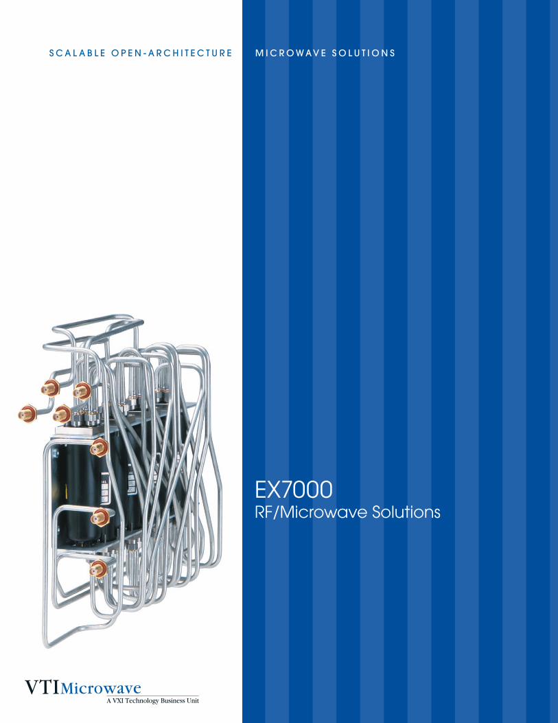
EX7000 RF/Microwave Solutions
S c a l a b l e O p e n - a r c h i t e c t u r e M i c r O w av e S O l u t i O n S
a M O D u l a r a p p r O a c h t O e n G i n e e r i n G a n D D e v e l O p i n G
ThE EX7000 FAMILYThe EX7000 family is the industry’s first series of scalable microwave subsystems built on an open-
architecture Ethernet/LXI platform. This innovative family of products simplifies the development
of custom RFIU requirements with its common hardware platform and software communications
interface, while maintaining the look and feel of a standard COTS product.
a COTS solution for custom RFIU requirements
n Configured easily into commercial-off-the-shelf products
n Supported and repeatable product builds
n Documented and designed for long-term worldwide support
n Embedded BOMs, configuration details, and component specifications are accessible via the web from anywhere in the world
common corporate-wide solution
n Based on LXI, a forward-looking Ethernet-based standard
n Provides the trust required for an OEM solution with VTI’s reputation for product longevity
n Supported by an experienced team of RF/Microwave engineers who can help you develop your system or develop one for you
n Leverage and build on your existing engineering investment
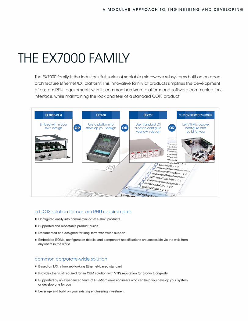
Embed within your own design
Use a platform to develop your design
Let VTI Microwave configure and build for you
Use standard LXI slices to configure your own design
OR OR OR
EX7000-OEM EX7400 EX72SF CUSTOM SERVICES GROUP
a M O D u l a r a p p r O a c h t O e n G i n e e r i n G a n D D e v e l O p i n G
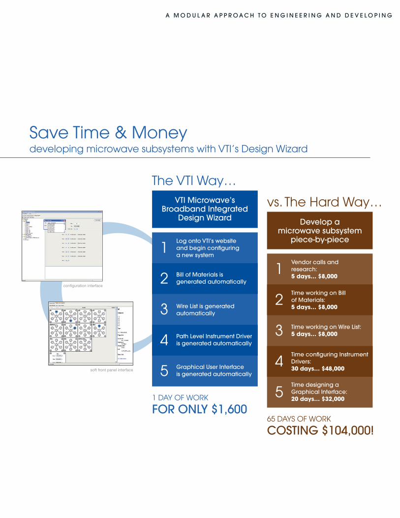
The VTI Way…
Save Time & Moneydeveloping microwave subsystems with VTI’s Design Wizard
1 DAY OF WORK
fOr Only $1,60065 DAYS OF WORK
cOStinG $104,000!
log onto vti’s website and begin configuring a new system
bill of Materials is generated automatically
wire list is generated automatically
path level instrument Driver is generated automatically
Graphical user interface is generated automatically
vti Microwave’sbroadband integrated
Design wizard Develop a microwave subsystem
piece-by-piece
vs. The hard Way…
1
2
3
4
5
1
2
3
4
5
vendor calls and research: 5 days… $8,000
time working on bill of Materials: 5 days… $8,000
time working on wire list: 5 days… $8,000
time configuring instrument Drivers: 30 days… $48,000
time designing aGraphical interface: 20 days… $32,000
configuration interface
soft front panel interface
a M O D u l a r a p p r O a c h t O e n G i n e e r i n G a n D D e v e l O p i n G
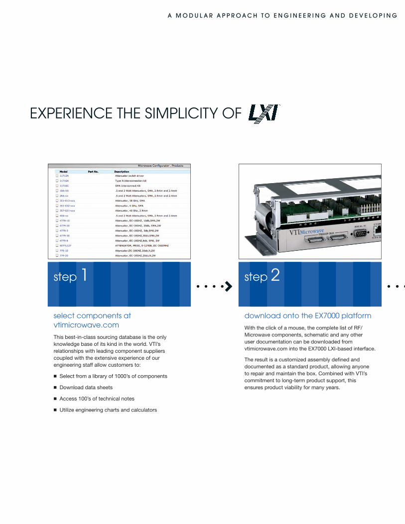
EXpERIEnCE ThE SIMpLICITY OF
select components at vtimicrowave.com
This best-in-class sourcing database is the only knowledge base of its kind in the world. VTI’s relationships with leading component suppliers coupled with the extensive experience of our engineering staff allow customers to:
n Select from a library of 1000’s of components
n Download data sheets
n Access 100’s of technical notes
n Utilize engineering charts and calculators
download onto the EX7000 platform
With the click of a mouse, the complete list of RF/Microwave components, schematic and any other user documentation can be downloaded from vtimicrowave.com into the EX7000 LXI-based interface.
The result is a customized assembly defined and documented as a standard product, allowing anyone to repair and maintain the box. Combined with VTI’s commitment to long-term product support, this ensures product viability for many years.
step 1 step 2
a M O D u l a r a p p r O a c h t O e n G i n e e r i n G a n D D e v e l O p i n G
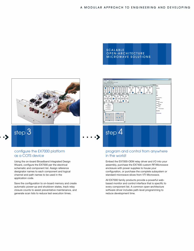
configure the EX7000 platform as a COTS device
Using the on-board Broadband Integrated Design Wizard, configure the EX7000 per the electrical schematic and component list. Assign reference designator names to each component and logical channel and path names to be used in the application code.
Save the configuration to on-board memory and create automatic power-up and shutdown states, track relay closure counts to assist preventative maintenance, and generate scan lists to reduce test execution times.
program and control from anywhere in the world!
Embed the EX7000-OEM relay driver and I/O into your assembly, purchase the EX7400 custom RF/Microwave enclosure with power supplies to house your configuration, or purchase the complete subsystem or standard microwave slices from VTI Microwave.
All EX7000 family products provide a powerful web- based monitor and control interface that is specific to every component list. A common open-architecture software driver includes path-level programming to reduce development time.
step 3 step 4
S c a l a b l e O p e n - a r c h i t e c t u r eM i c r O w a v e S O l u t i O n S
a M O D u l a r a p p r O a c h t O e n G i n e e r i n G a n D D e v e l O p i n G
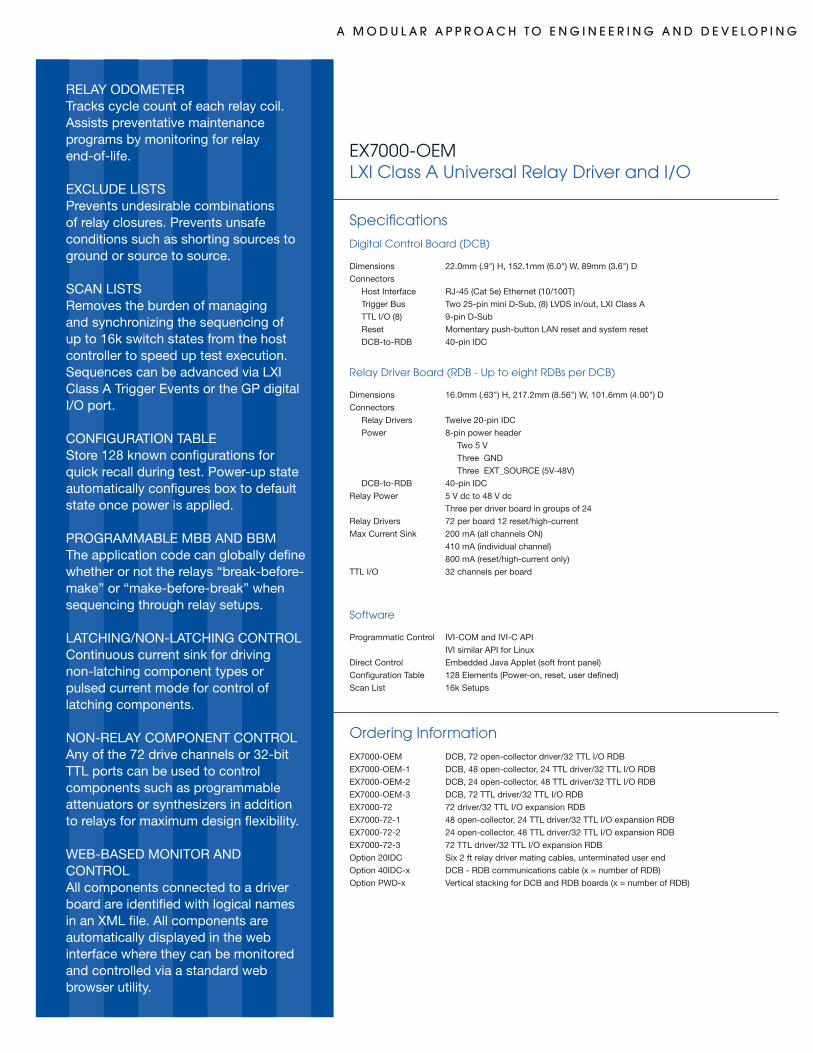
EX7000-OEM LXI CLASS A UnIVERSAL RELAY DRIVER AnD I/O
e X p e r i e n c e t h e M O D u l a r i t y O f l X i
product longevity
VTI Microwave integrates the EX7000-OEM into all LXI RF/Microwave products in support of our commitment to provide products based on open-system platforms and ensure long-term viability. The EX7000-OEM is the natural solution for engineers who wish to leverage an open-platform architecture for internal requirements, and provide a common infrastructure that can be reused for future application needs.
unmatched performance and modularity
The EX7000-OEM is controlled via a standard Ethernet interface and conforms to all the powerful features of LXI Class A, which includes an industry standard discovery method, LVDS triggering and IEEE-1588 for precise time-based synchronization with other LXI devices. An EX7000-OEM provides 72 driver channels capable of sinking 410 mA, 12 reset/control lines, and a 32-bit TTL port; all designed for controlling virtually any type of RF/Microwave relay or component.
Up to seven expansion driver boards (EX7000-72) can be added for designs that require additional drive control for a maximum of 576 high-current sink channels, 96 reset/control lines and 256 TLL I/O ports.
reduced costs through standardization
The greatest value that the EX7000-OEM brings any organization is its ability to eliminate the need to rely on a proprietary software driver and communications interface during application code development, which can result in a unique implementation for every configuration. Application programs can simply command the RFIU or assembly utilizing “path-level” IVI programming (C or COM) on either Linux or Windows machines. A powerful, very intuitive, on-board JAVA applet used in conjunction with VTI Microwave’s on-line “Best in Class” sourcing database enables the EX7000-OEM to be adapted internally for any mix of components that need to be programmatically controlled.
sustained global service and support
One of the biggest challenges often presented by an in-house development occurs years later when it is time to service or reproduce the hardware. Poor documentation and lack of access to the original designers can result in costly roadblocks that must be cleared. The EX7000-OEM allows users to maintain design-critical information, including component attributes and links to datasheets, and access this information from anywhere in the world. Relay cycle counts, which can assist in preventative maintenance, and fault indicator circuitry available on some components can also be monitored remotely to further reduce system downtime.
a M O D u l a r a p p r O a c h t O e n G i n e e r i n G a n D D e v e l O p i n G
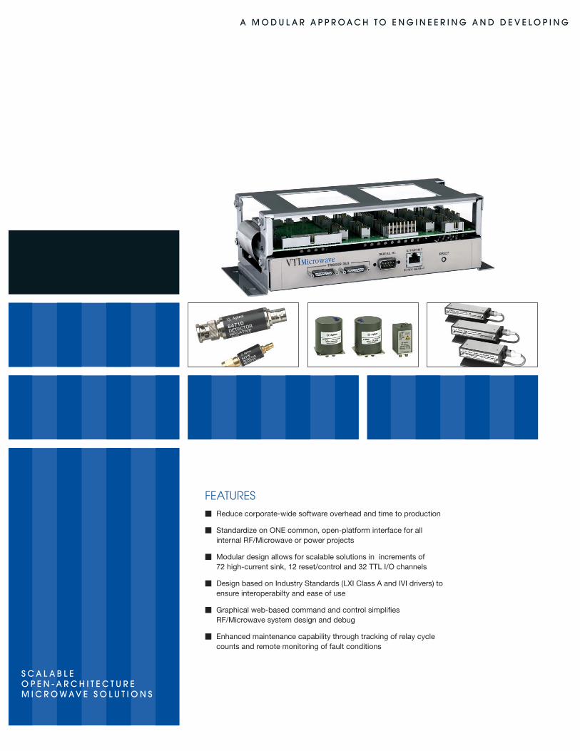
FEATURESm Reduce corporate-wide software overhead and time to production
m Standardize on ONE common, open-platform interface for all internal RF/Microwave or power projects
m Modular design allows for scalable solutions in increments of 72 high-current sink, 12 reset/control and 32 TTL I/O channels
m Design based on Industry Standards (LXI Class A and IVI drivers) to ensure interoperabilty and ease of use
m Graphical web-based command and control simplifies RF/Microwave system design and debug
m Enhanced maintenance capability through tracking of relay cycle counts and remote monitoring of fault conditions
S c a l a b l e O p e n - a r c h i t e c t u r eM i c r O w a v e S O l u t i O n S
a M O D u l a r a p p r O a c h t O e n G i n e e r i n G a n D D e v e l O p i n G
RELAy ODOMETERTracks cycle count of each relay coil. Assists preventative maintenance programs by monitoring for relay end-of-life.
EXCLUDE LISTSPrevents undesirable combinations of relay closures. Prevents unsafe conditions such as shorting sources to ground or source to source.
SCAN LISTSRemoves the burden of managing and synchronizing the sequencing of up to 16k switch states from the host controller to speed up test execution. Sequences can be advanced via LXI Class A Trigger Events or the GP digital I/O port.
CONFIGURATION TABLEStore 128 known configurations for quick recall during test. Power-up state automatically configures box to default state once power is applied.
PROGRAMMABLE MBB AND BBMThe application code can globally define whether or not the relays “break-before-make” or “make-before-break” when sequencing through relay setups.
LATChING/NON-LATChING CONTROLContinuous current sink for driving non-latching component types or pulsed current mode for control of latching components.
NON-RELAy COMPONENT CONTROLAny of the 72 drive channels or 32-bit TTL ports can be used to control components such as programmable attenuators or synthesizers in addition to relays for maximum design flexibility.
WEB-BASED MONITOR AND CONTROLAll components connected to a driver board are identified with logical names in an XML file. All components are automatically displayed in the web interface where they can be monitored and controlled via a standard web browser utility.
EX7000-OEMLXI Class A Universal Relay Driver and I/O
Specifications
Digital Control Board (DCB)
Dimensions 22.0mm (.9") h, 152.1mm (6.0") W, 89mm (3.6") D
Connectors
host Interface RJ-45 (Cat 5e) Ethernet (10/100T)
Trigger Bus Two 25-pin mini D-Sub, (8) LVDS in/out, LXI Class A
TTL I/O (8) 9-pin D-Sub
Reset Momentary push-button LAN reset and system reset
DCB-to-RDB 40-pin IDC
Relay Driver Board (RDB - Up to eight RDBs per DCB)
Dimensions 16.0mm (.63") h, 217.2mm (8.56") W, 101.6mm (4.00") D
Connectors
Relay Drivers Twelve 20-pin IDC
Power 8-pin power header
Two 5 V
Three GND
Three EXT_SOURCE (5V-48V)
DCB-to-RDB 40-pin IDC
Relay Power 5 V dc to 48 V dc
Three per driver board in groups of 24
Relay Drivers 72 per board 12 reset/high-current
Max Current Sink 200 mA (all channels ON)
410 mA (individual channel)
800 mA (reset/high-current only)
TTL I/O 32 channels per board
Software
Programmatic Control IVI-COM and IVI-C API
IVI similar API for Linux
Direct Control Embedded Java Applet (soft front panel)
Configuration Table 128 Elements (Power-on, reset, user defined)
Scan List 16k Setups
Ordering Information
EX7000-OEM DCB, 72 open-collector driver/32 TTL I/O RDB
EX7000-OEM-1 DCB, 48 open-collector, 24 TTL driver/32 TTL I/O RDB
EX7000-OEM-2 DCB, 24 open-collector, 48 TTL driver/32 TTL I/O RDB
EX7000-OEM-3 DCB, 72 TTL driver/32 TTL I/O RDB
EX7000-72 72 driver/32 TTL I/O expansion RDB
EX7000-72-1 48 open-collector, 24 TTL driver/32 TTL I/O expansion RDB
EX7000-72-2 24 open-collector, 48 TTL driver/32 TTL I/O expansion RDB
EX7000-72-3 72 TTL driver/32 TTL I/O expansion RDB
Option 20IDC Six 2 ft relay driver mating cables, unterminated user end
Option 40IDC-x DCB - RDB communications cable (x = number of RDB)
Option PWD-x Vertical stacking for DCB and RDB boards (x = number of RDB)
a M O D u l a r a p p r O a c h t O e n G i n e e r i n G a n D D e v e l O p i n G
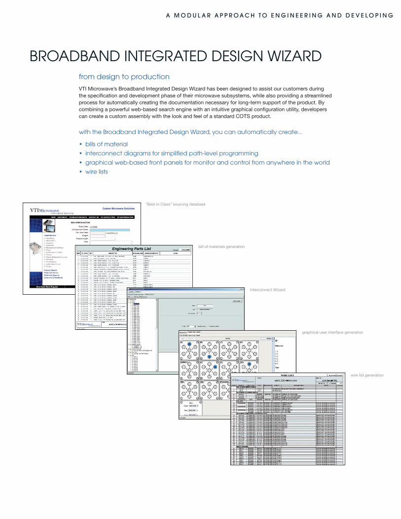
BROADBAnD InTEgRATED DESIgn WIzARDfrom design to production
VTI Microwave’s Broadband Integrated Design Wizard has been designed to assist our customers during the specification and development phase of their microwave subsystems, while also providing a streamlined process for automatically creating the documentation necessary for long-term support of the product. By combining a powerful web-based search engine with an intuitive graphical configuration utility, developers can create a custom assembly with the look and feel of a standard COTS product.
with the Broadband Integrated Design Wizard, you can automatically create...
• billsofmaterial
• interconnectdiagramsforsimplifiedpath-levelprogramming
• graphicalweb-basedfrontpanelsformonitorandcontrolfromanywhereintheworld
• wirelists
“Best in Class” sourcing database
bill of materials generation
Interconnect Wizard
graphical user interface generation
wire list generation
a M O D u l a r a p p r O a c h t O e n G i n e e r i n G a n D D e v e l O p i n G
EX7300-EX7600 LXI CLASS A CUSTOM RF/MICROWAVE EnCLOSURES
integrated enclosures simplify customization
The EX7300 (3U) - EX7600 (6U) are complete enclosures that include a 150 W power supply, the EX7000-OEM LXI digital interface and driver card, fans for cooling, and a removable tray for mounting components and cables. These units are intended for customers who wish to develop, build, and support their own RF/Microwave, optical, or power interface subassemblies while minimizing the time spent developing a software and communications interface. The power supply, along with the LXI Class A controller and relay driver boards is placed in the enclosure such that the RF signals passing through the box are not adversely impacted by any stray energy.
flexible control based on the EX7000-OEM
Consistent with all products within the EX7000 family, the EX7300 - EX7600 enclosures leverage off the powerful command and control options of the EX7000-OEM (see EX7000-OEM). A list of components used in the design can be built through www.vtimicrowave.com using a web-based interface that is coupled with an extensive component library. This list can be uploaded to the custom enclosure and a JAVA-driven graphical configuration utility is then employed to programmatically emulate the schematic, while providing a “path-level” IVI driver interface and an intuitive, soft front panel for easy debug and control.
efficient design facilitates easy development
A removable tray allows the enclosure to be easily “punched” for the mounting of components and cables. Additionally, 3D drawings of the cable tray can be made available for users who wish to mechanically design the custom tray and have either VTI Microwave or a machine shop fabricate the subassembly. The component tray also allows I/O connectors to be mounted on either the rear or front panels providing the flexibility to keep external cable lengths to the enclosure at a minimum, regardless of the connector orientation of the other system assets.
e X p e r i e n c e t h e S i M p l i c i t y O f l X i
a M O D u l a r a p p r O a c h t O e n G i n e e r i n G a n D D e v e l O p i n G
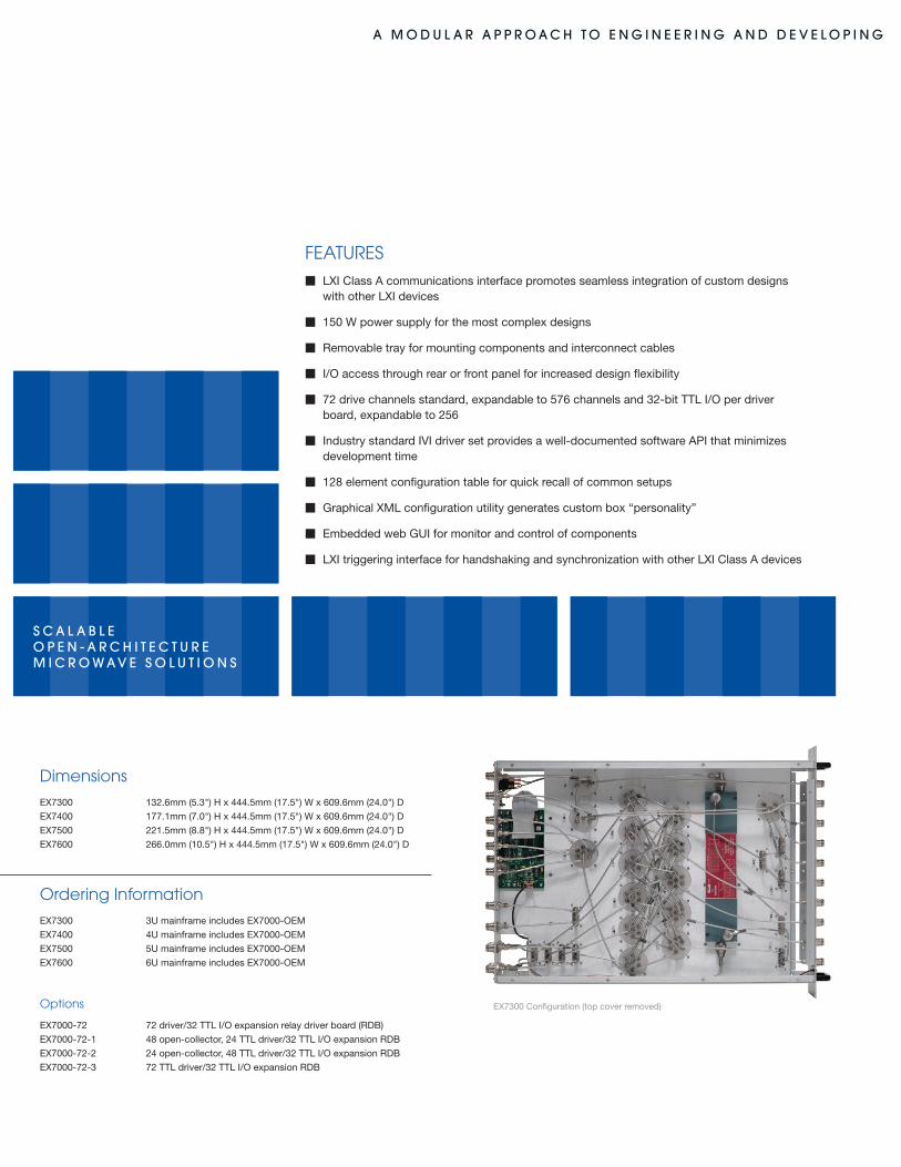
Dimensions
EX7300 132.6mm (5.3") h x 444.5mm (17.5") W x 609.6mm (24.0") D
EX7400 177.1mm (7.0") h x 444.5mm (17.5") W x 609.6mm (24.0") D
EX7500 221.5mm (8.8") h x 444.5mm (17.5") W x 609.6mm (24.0") D
EX7600 266.0mm (10.5") h x 444.5mm (17.5") W x 609.6mm (24.0") D
Ordering Information
EX7300 3U mainframe includes EX7000-OEM
EX7400 4U mainframe includes EX7000-OEM
EX7500 5U mainframe includes EX7000-OEM
EX7600 6U mainframe includes EX7000-OEM
Options
EX7000-72 72 driver/32 TTL I/O expansion relay driver board (RDB)
EX7000-72-1 48 open-collector, 24 TTL driver/32 TTL I/O expansion RDB
EX7000-72-2 24 open-collector, 48 TTL driver/32 TTL I/O expansion RDB
EX7000-72-3 72 TTL driver/32 TTL I/O expansion RDB
FEATURESm LXI Class A communications interface promotes seamless integration of custom designs with other LXI devices
m 150 W power supply for the most complex designs
m Removable tray for mounting components and interconnect cables
m I/O access through rear or front panel for increased design flexibility
m 72 drive channels standard, expandable to 576 channels and 32-bit TTL I/O per driver board, expandable to 256
m Industry standard IVI driver set provides a well-documented software API that minimizes development time
m 128 element configuration table for quick recall of common setups
m Graphical XML configuration utility generates custom box “personality”
m Embedded web GUI for monitor and control of components
m LXI triggering interface for handshaking and synchronization with other LXI Class A devices
S c a l a b l e O p e n - a r c h i t e c t u r eM i c r O w a v e S O l u t i O n S
EX7300 Configuration (top cover removed)
a M O D u l a r a p p r O a c h t O e n G i n e e r i n G a n D D e v e l O p i n G
modularity and density
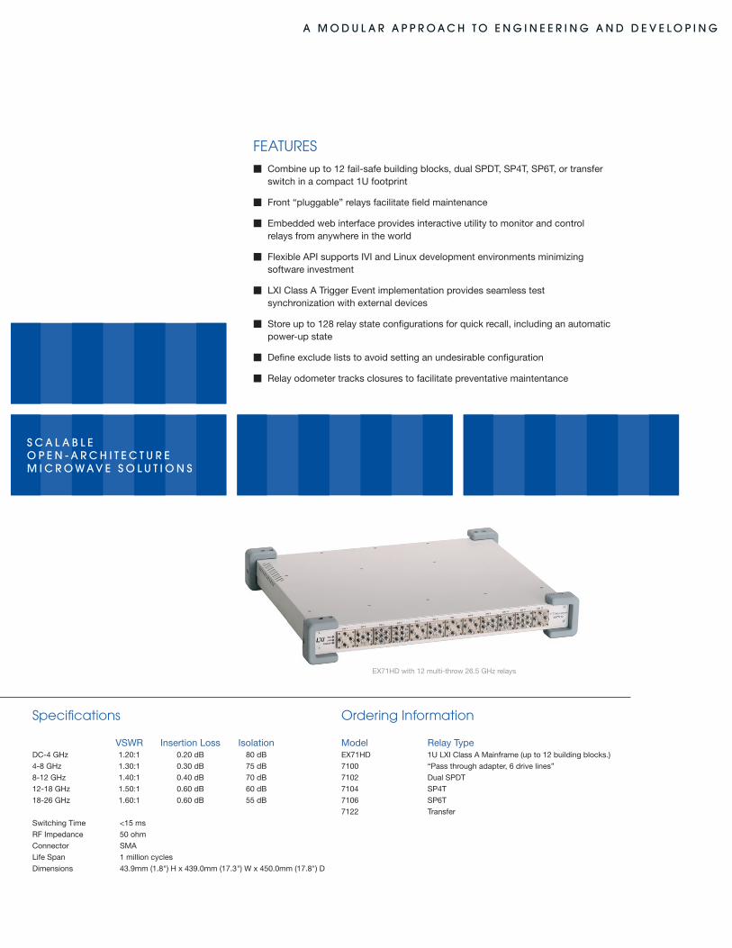
The EX71hD is the highest density microwave switching platform in the industry and is designed to address applications that require non-latching relays and an operating range of up to 26.5 Ghz. Any combination of up to twelve building blocks can be housed in a single 1U rack LXI Class A enclosure. Building block topologies include dual SPDTs, SP4T, SP6T, and transfer switches, as well as a 6-line pass through adapter that can be used to drive external circuitry.
To configure your switch simply follow these three steps
Step 1 Start with the EX71hD base unit. It holds up to twelve microwave building blocks in one 1U rack (1.75") height.
Step 2 Select up to twelve microwave building blocks
Step 3 Contact VTI Microwave for price and delivery
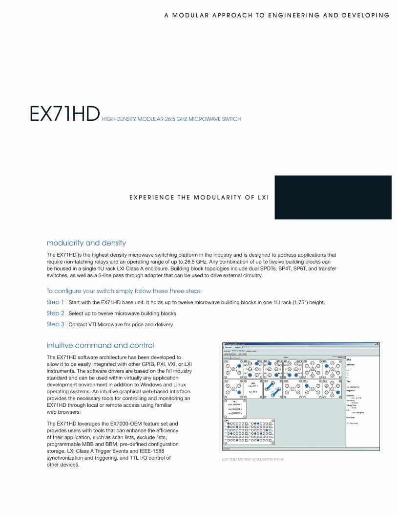
EX71hD hIgh-DEnSITY, MODULAR 26.5 ghz MICROWAVE SWITCh
EX71hD Monitor and Control Panel
intuitive command and control
The EX71hD software architecture has been developed to allow it to be easily integrated with other GPIB, PXI, VXI, or LXI instruments. The software drivers are based on the IVI industry standard and can be used within virtually any application development environment in addition to Windows and Linux operating systems. An intuitive graphical web-based interface provides the necessary tools for controlling and monitoring an EX71hD through local or remote access using familiar web browsers.
The EX71hD leverages the EX7000-OEM feature set and provides users with tools that can enhance the efficiency of their application, such as scan lists, exclude lists, programmable MBB and BBM, pre-defined configuration storage, LXI Class A Trigger Events and IEEE-1588 synchronization and triggering, and TTL I/O control of other devices.
e X p e r i e n c e t h e M O D u l a r i t y O f l X i
a M O D u l a r a p p r O a c h t O e n G i n e e r i n G a n D D e v e l O p i n G
FEATURESm Combine up to 12 fail-safe building blocks, dual SPDT, SP4T, SP6T, or transfer switch in a compact 1U footprint
m Front “pluggable” relays facilitate field maintenance
m Embedded web interface provides interactive utility to monitor and control relays from anywhere in the world
m Flexible API supports IVI and Linux development environments minimizing software investment
m LXI Class A Trigger Event implementation provides seamless test synchronization with external devices
m Store up to 128 relay state configurations for quick recall, including an automatic power-up state
m Define exclude lists to avoid setting an undesirable configuration
m Relay odometer tracks closures to facilitate preventative maintentance
EX71hD with 12 multi-throw 26.5 Ghz relays
Specifications
VSWR Insertion Loss IsolationDC-4 Ghz 1.20:1 0.20 dB 80 dB
4-8 Ghz 1.30:1 0.30 dB 75 dB
8-12 Ghz 1.40:1 0.40 dB 70 dB
12-18 Ghz 1.50:1 0.60 dB 60 dB
18-26 Ghz 1.60:1 0.60 dB 55 dB
Switching Time <15 ms
RF Impedance 50 ohm
Connector SMA
Life Span 1 million cycles
Dimensions 43.9mm (1.8") h x 439.0mm (17.3") W x 450.0mm (17.8") D
Ordering Information
Model Relay TypeEX71hD 1U LXI Class A Mainframe (up to 12 building blocks.)
7100 “Pass through adapter, 6 drive lines”
7102 Dual SPDT
7104 SP4T
7106 SP6T
7122 Transfer
S c a l a b l e O p e n - a r c h i t e c t u r eM i c r O w a v e S O l u t i O n S
a M O D u l a r a p p r O a c h t O e n G i n e e r i n G a n D D e v e l O p i n G
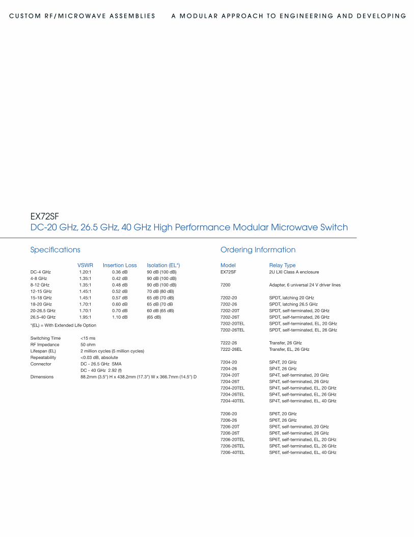
excellent performance in a compact footprint
The EX72SF is a high-density microwave switching platform that is designed to address applications that demand maximum performance, flexible design options, and an operating range to either 20 Ghz, 26.5 Ghz or 40 Ghz. Configuration options include self-termination of unused ports and an expected lifetime of > 5 million cycles. Any combination of up to twelve latching building blocks can be housed in a single 2U rack LXI Class A enclosure. Building block topologies include SPDT, SP4T, SP6T, and transfer switches, as well as a 6-line pass-through adapter and 32-bit TTL I/O bus that can be used to drive external circuitry.
To configure your switch simply follow these three steps
Step 1 Start with the EX72SF base unit. It holds up to twelve microwave building blocks in two rack U (3.5") height
Step 2 Select up to six SPDT and six multiport switches
Step 3 Contact VTI Microwave for price and delivery
EX72SF DC-20 ghz, 26.5 ghz, 40 ghz hIgh pERFORMAnCE MODULAR MICROWAVE SWITCh
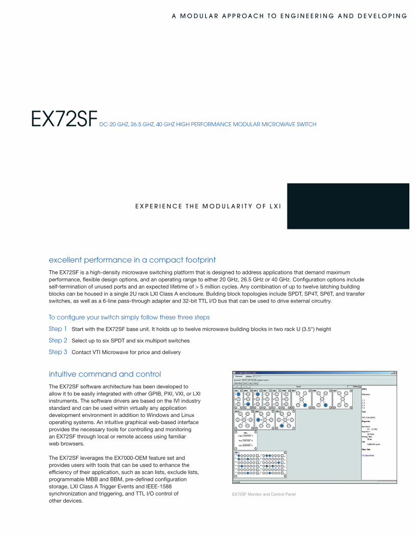
intuitive command and control
The EX72SF software architecture has been developed to allow it to be easily integrated with other GPIB, PXI, VXI, or LXI instruments. The software drivers are based on the IVI industry standard and can be used within virtually any application development environment in addition to Windows and Linux operating systems. An intuitive graphical web-based interface provides the necessary tools for controlling and monitoring an EX72SF through local or remote access using familiar web browsers.
The EX72SF leverages the EX7000-OEM feature set and provides users with tools that can be used to enhance the efficiency of their application, such as scan lists, exclude lists, programmable MBB and BBM, pre-defined configuration storage, LXI Class A Trigger Events and IEEE-1588 synchronization and triggering, and TTL I/O control of other devices.
e X p e r i e n c e t h e M O D u l a r i t y O f l X i
EX72SF Monitor and Control Panel
a M O D u l a r a p p r O a c h t O e n G i n e e r i n G a n D D e v e l O p i n G
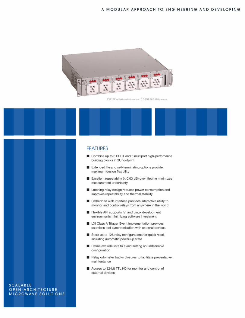
EX72SF with 6 multi-throw and 6 SPDT 26.5 Ghz relays
S c a l a b l e O p e n - a r c h i t e c t u r eM i c r O w a v e S O l u t i O n S
FEATURESm Combine up to 6 SPDT and 6 multiport high-perfomance building blocks in 2U footprint
m Extended life and self-terminating options provide maximum design flexibility
m Excellent repeatablity (< 0.03 dB) over lifetime minimizes measurement uncertainty m Latching relay design reduces power consumption and improves repeatability and thermal stability
m Embedded web interface provides interactive utility to monitor and control relays from anywhere in the world
m Flexible API supports IVI and Linux development environments minimizing software investment
m LXI Class A Trigger Event implementation provides seamless test synchronization with external devices
m Store up to 128 relay configurations for quick recall, including automatic power-up state
m Define exclude lists to avoid setting an undesirable configuration
m Relay odometer tracks closures to facilitate preventative maintentance
m Access to 32-bit TTL I/O for monitor and control of external devices
a M O D u l a r a p p r O a c h t O e n G i n e e r i n G a n D D e v e l O p i n G
measurement integrity, repeatability and long life
The goal of a system engineer is to make a switching interface as invisible as possible to the rest of the system in order to maximize the integrity of the signals passing through it. The EX72SF uses relays that employ superior design technology and deliver unmatched isolation and minimal crosstalk resulting in a high-degree of confidence in measurement accuracy. however, the quality of a system design also depends on its ability to deliver repeatable measurement performance. Repeatability specifies the measure of change that occurs in insertion loss over the rated life of the switch, and systems that utilize relays with performance that drifts over time drive the need for costly recalibration of the system. EX72SF switches guarantee an industry-leading repeatability of insertion loss within a maximum of 0.03 dB throughout their rated lifetime to provide consistent measurement performance.
The EX72SF platform further drives down the total cost of ownership by providing operating life of > 2 million cycles. Many automated test systems can execute thousands of cycles per day on a single relay, and for demanding applications such as these, extended life (EL) options are available to extend the operating life to > 5 million cycles. With a powerful combination of economical price and outstanding performance, the EX72SF is capable of handling a wide array of application spaces ranging from aerospace and defense to commercial wireless products.
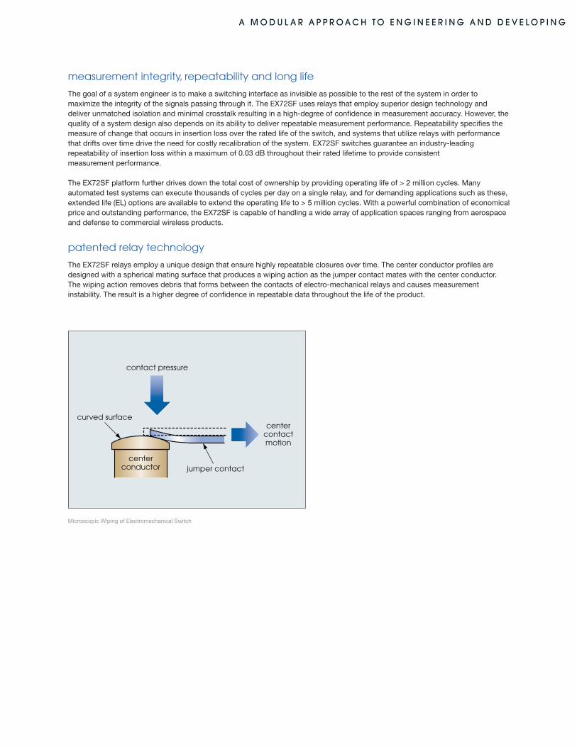
patented relay technology
The EX72SF relays employ a unique design that ensure highly repeatable closures over time. The center conductor profiles are designed with a spherical mating surface that produces a wiping action as the jumper contact mates with the center conductor. The wiping action removes debris that forms between the contacts of electro-mechanical relays and causes measurement instability. The result is a higher degree of confidence in repeatable data throughout the life of the product.
contact pressure
centercontactmotion
centerconductor
curved surface
jumper contact
Microscopic Wiping of Electromechanical Switch
a M O D u l a r a p p r O a c h t O e n G i n e e r i n G a n D D e v e l O p i n G c u S t O M r f / M i c r O w a v e a S S e M b l i e S
Ordering Information
Model Relay TypeEX72SF 2U LXI Class A enclosure
7200 Adapter, 6 universal 24 V driver lines
7202-20 SPDT, latching 20 Ghz
7202-26 SPDT, latching 26.5 Ghz
7202-20T SPDT, self-terminated, 20 Ghz
7202-26T SPDT, self-terminated, 26 Ghz
7202-20TEL SPDT, self-terminated, EL, 20 Ghz
7202-26TEL SPDT, self-terminated, EL, 26 Ghz
7222-26 Transfer, 26 Ghz
7222-26EL Transfer, EL, 26 Ghz
7204-20 SP4T, 20 Ghz
7204-26 SP4T, 26 Ghz
7204-20T SP4T, self-terminated, 20 Ghz
7204-26T SP4T, self-terminated, 26 Ghz
7204-20TEL SP4T, self-terminated, EL, 20 Ghz
7204-26TEL SP4T, self-terminated, EL, 26 Ghz
7204-40TEL SP4T, self-terminated, EL, 40 Ghz
7206-20 SP6T, 20 Ghz
7206-26 SP6T, 26 Ghz
7206-20T SP6T, self-terminated, 20 Ghz
7206-26T SP6T, self-terminated, 26 Ghz
7206-20TEL SP6T, self-terminated, EL, 20 Ghz
7206-26TEL SP6T, self-terminated, EL, 26 Ghz
7206-40TEL SP6T, self-terminated, EL, 40 Ghz
EX72SFDC-20 ghz, 26.5 ghz, 40 ghz high performance Modular Microwave Switch
Specifications
VSWR Insertion Loss Isolation (EL*)DC-4 Ghz 1.20:1 0.36 dB 90 dB (100 dB)
4-8 Ghz 1.35:1 0.42 dB 90 dB (100 dB)
8-12 Ghz 1.35:1 0.48 dB 90 dB (100 dB)
12-15 Ghz 1.45:1 0.52 dB 70 dB (80 dB)
15-18 Ghz 1.45:1 0.57 dB 65 dB (70 dB)
18-20 Ghz 1.70:1 0.60 dB 65 dB (70 dB
20-26.5 Ghz 1.70:1 0.70 dB 60 dB (65 dB)
26.5-40 Ghz 1.95:1 1.10 dB (65 dB)
*(EL) = With Extended Life Option
Switching Time <15 ms
RF Impedance 50 ohm
Lifespan (EL) 2 million cycles (5 million cycles)
Repeatability <0.03 dB, absolute
Connector DC - 26.5 Ghz SMA
DC - 40 Ghz 2.92 (f)
Dimensions 88.2mm (3.5") h x 438.2mm (17.3") W x 366.7mm (14.5") D
a M O D u l a r a p p r O a c h t O e n G i n e e r i n G a n D D e v e l O p i n G
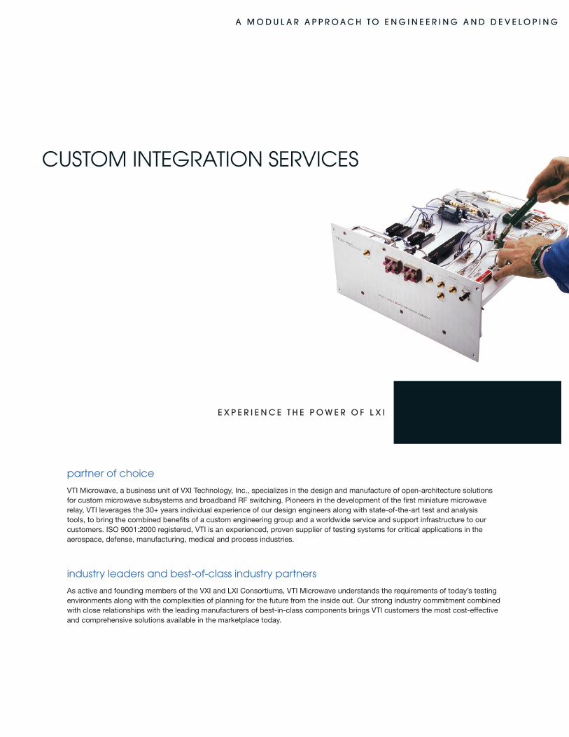
partner of choice
VTI Microwave, a business unit of VXI Technology, Inc., specializes in the design and manufacture of open-architecture solutions for custom microwave subsystems and broadband RF switching. Pioneers in the development of the first miniature microwave relay, VTI leverages the 30+ years individual experience of our design engineers along with state-of-the-art test and analysis tools, to bring the combined benefits of a custom engineering group and a worldwide service and support infrastructure to our customers. ISO 9001:2000 registered, VTI is an experienced, proven supplier of testing systems for critical applications in the aerospace, defense, manufacturing, medical and process industries.
industry leaders and best-of-class industry partners
As active and founding members of the VXI and LXI Consortiums, VTI Microwave understands the requirements of today’s testing environments along with the complexities of planning for the future from the inside out. Our strong industry commitment combined with close relationships with the leading manufacturers of best-in-class components brings VTI customers the most cost-effective and comprehensive solutions available in the marketplace today.
CUSTOM InTEgRATIOn SERVICES
e X p e r i e n c e t h e p O w e r O f l X i
a M O D u l a r a p p r O a c h t O e n G i n e e r i n G a n D D e v e l O p i n G
cost-effective and flexible solutions
VTI solutions leverage a unique combination of modularity and reusability,providing the greatest level of flexibility throughout the operational life of a system, from both a hardware and software perspective. Whether VTIMicrowave solutions are used as an in-house development platform, embedded within a design, or configured and built to specification by VTI’s Custom Engineering group, VTI customers have confidence in using the best performing, highest quality products available.
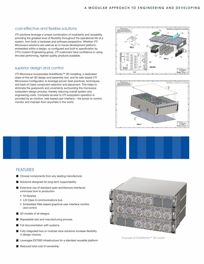
superior design and control
VTI Microwave incorporates SolidWorks™ 3D modeling, a dedicatedstate-of-the-art 3D design and assembly tool, and its web-based VTIMicrowave Configurator, to leverage proven best practices, techniques, and best-of-class component selection and placement. This helps to eliminate the guesswork and uncertainty surrounding the microwave subsystem design process, thereby reducing overall system and engineering costs. Complete access to VTI subsystem operation is provided by an intuitive, web-based user interface – the power to control, monitor and maintain from anywhere in the world.
Example of SolidWorks™ 3D model
FEATURESm Choose components from any leading manufacturer
m Solutions designed for long-term supportability
m Extensive use of standard open-architecture interfaces minimizes time to production
• IVIlibraries
• LXIClassAcommunicationsbus
• EmbeddedWeb-basedgraphicaluserinterfacemonitor and control
m 3D models of all designs
m Repeatable test and manufacturing process
m Full documentation with systems
m Fully integrated box or modular slice solutions increase flexibility in design choices
m Leverages EX7000 infrastructure for a standard reusable platform
m Reduced total cost of ownership
VTI Microwave, a VXI Technology Business Unit, combines the benefits of
a local integrator with those of a worldwide product manufacturer. For
close to 20 years we have led the industry with modular high-density
solutions. We manufacture and support all key control hardware
and software. Our RF/Microwave engineers have over 30 plus years
experience designing the same types of products our customers test.
VTI Microwave ensures our customers get:
•measurementintegrity
•modularityanddensity
•productlongevity
•lowesttotalcostofownership
w w w .v t i m i c r o w a v e . c o m
949.955.1894•Fax:949.955.3041