sampling and analysis procedure for the determination of ... fileleaving cooling towers in...
TRANSCRIPT
Istituto di Geoscienze e Georisorse – IGG HEAD OFFICES
Istituto di Chimica dei Composti Organometallici – ICCOM Unità Organizzativa di Supporto di Pisa
Area Ricerca CNR di Pisa - via G. Moruzzi, 1 - 56124 Pisa
Sampling and analysis procedure for the determination of mercury
leaving cooling towers in geothermal power stations
IGG-ICCOM/CNR-3 METHOD
(M3)
Authors: Alessandro Lenzi4, Antonio Caprai1, Alessandro D’Ulivo2, Massimo Onor2, Marco Carlo
Mascherpa2, Marco Paci4, Romina Taccone4, Alessandro Bettini4, Antonio Ciompi4
In collaboration with ARPAT - Geothermal Sector, ARPAT Laboratory Sector AVS Siena3
1C.N.R.- National Research Council (CNR),
Institute of Geo-Sciences and Geo-Resources
2C.N.R.- National Research Council (CNR),
Institute of Organometallic Chemistry, Scuola Superiore di Pisa
3Tuscany Regional Environmental Protection Agency - ARPAT
4Enel Green Power
Method: IGG-ICCOM/CNR -3 (M3) Rev: 2 Edition: 13.09.2017
IGG/CNR-3 METHOD
2
CONTENTS
1. PURPOSE AND SCOPE OF APPLICATION .................................................................................................... 4
2. REFERENCE DOCUMENTS .......................................................................................................................... 4
3. TERMS AND DEFINITIONS .......................................................................................................................... 4
4. PRINCIPLE .................................................................................................................................................. 5
5. SAMPLING EQUIPMENT ............................................................................................................................. 6
5.1 SAMPLING CONDITIONS ........................................................................................................................ 6
5.2 GENERAL REQUIREMENTS ..................................................................................................................... 6
5.3 SAMPLING EQUIPMENT ......................................................................................................................... 7
5.4 ABSORBERS ............................................................................................................................................ 7
5.5 CONNECTIONS ....................................................................................................................................... 8
5.6 STORAGE FLASKS AND CONTAINERS ..................................................................................................... 8
5.7 MATERIALS FOR SAMPLING EQUIPMENT .............................................................................................. 8
5.8 SUCTION UNIT ....................................................................................................................................... 9
5.9 GAS VOLUME MEASURING UNIT ........................................................................................................... 9
5.10 ADDITIONAL EQUIPMENT ...................................................................................................................... 9
6. REAGENTS .................................................................................................................................................. 9
6.1 GENERAL INFORMATION ....................................................................................................................... 9
6.2 REAGENTS FOR PRE-CLEANING OF SAMPLING EQUIPMENT .............................................................. 10
6.3 SELECTING ABSORPTION SOLUTIONS .................................................................................................. 10
6.3.1 General Information ........................................................................................................................ 10
6.3.2 Absorption solution (KMnO4 0.14M / H2SO4 1.08M) ....................................................................... 10
6.4 REAGENTS FOR RINSING THE SAMPLING LINE AFTER SAMPLING ....................................................... 10
6.4.1 Solution of HNO3, 10%m/m ............................................................................................................. 10
6.4.2 Rinsing solution for absorbers. ........................................................................................................ 11
7. PROCEDURE ............................................................................................................................................. 11
7.1 GENERAL REQUIREMENTS ................................................................................................................... 11
7.2 PRE-CLEANING THE EQUIPMENT ......................................................................................................... 11
7.3 PREPARING AND INSTALLING THE EQUIPMENT .................................................................................. 12
7.3.1 Installing the absorbers ................................................................................................................... 12
7.3.2 Seal tests .......................................................................................................................................... 12
7.3.3 Installing the equipment in the sampling position .......................................................................... 12

IGG/CNR-3 METHOD
3
7.4 BLANK SAMPLING ................................................................................................................................ 13
7.5 SAMPLING PERFORMANCES ................................................................................................................ 13
7.6 DISMANTLING THE EQUIPMENT ......................................................................................................... 13
7.6.1 Rinse the connection pipes on the first absorber ........................................................................... 13
7.6.2 Collecting absorption solutions from absorbers ............................................................................. 13
7.6.3 Rinsing the sampling equipment .................................................................................................... 14
7.7 SAMPLE STORAGE REQUIREMENTS..................................................................................................... 14
7.8 PRE-TREATMENT PRIOR TO ANALYSIS ................................................................................................. 14
7.8.1 General Information ........................................................................................................................ 14
7.8.2 Absorption solution ......................................................................................................................... 14
7.8.3 Rinsing solution ............................................................................................................................... 14
7.9 ANALYSIS .............................................................................................................................................. 14
8. REPORTING THE RESULTS ........................................................................................................................ 14
8.1 TOTAL MERCURY CONTENT ................................................................................................................. 14
8.2 VOLUME OF GAS UNDER REFERENCE CONDITIONS ............................................................................ 15
8.3 CALCULATING THE GAS FLOW FROM THE COOLING TOWERS ............................................................ 15
8.4 ACCEPTABLE OF REPLICATIONS ........................................................................................................... 16
8.5 PERFORMANCE CHARACTERISTICS ...................................................................................................... 16
9. TEST REPORT ............................................................................................................................................ 16
APPENDIX A: SAMPLING EQUIPMENT CLEANING PROCEDURE ...................................................................... 18
APPENDIX B: ACCEPTABLE OF REPLICATED DATA (THREE REPLICATIONS IN PARALLEL) ................................ 19

IGG/CNR-3 METHOD
4
Sampling and analysis procedure for the determination of mercury leaving cooling
towers in geothermal power stations
1. PURPOSE AND SCOPE OF APPLICATION
This method is an adaptation of the UNI EN 13211:2003 standard "Air Quality, Stationary Source Emission,
Manual Method for the Determination of Total Mercury" for correct sampling and analysis of total mercury
in gaseous effluents emitted by cooling towers in geothermal power stations. This method extends the field
of application to the emissions by geothermal power stations and the measurement range of the above-
mentioned UNI EN 13211:2003 method to the following values:
Concentration of mercury between 20 ng/Nm3 and 500 µg/Nm3 (the original standard is validated for concentrations of mercury between 1 µg/Nm3 and 500 µg/Nm3).
Oxygen in the sampled fluid ≤ 21% vol. on dry gas (the original standard is validated for concentrations of oxygen between 8% and 15% vol.).
Temperature of the sampled fluid between 10°C and 60°C (the original standard is validated for temperatures of the sampled gas between 60 and 140 °C).
2. REFERENCE DOCUMENTS
This method refers to dispositions contained in other publications. These references to standards with
related updates are indicated at appropriate points in the text and are listed below.
[1] UNI EN 1483:2008 “Water quality – Determination of mercury”
[2] UNI EN 13284-1:2003 “Stationary source emissions - Determination of low range mass concentrations of dust - Manual gravimetric method”
[3] EPA 7470A:1994 “Mercury in liquid waste (manual cold-vapor technique)”
[4] EPA 6010D:2014 “Inductively Coupled Plasma - Atomic Emission Spectrometry”
[5] UNI EN ISO 16911-1:2013 “Emissioni da sorgente fissa, determinazione manuale e automatica della velocità di flussi in condotti, parte 1: metodo di riferimento manuale”
[6] UNI EN 15259:2008 “Qualità dell’aria, misurazione di emissione da sorgente fissa, requisiti delle sezioni e dei siti di misurazione e dell’obiettivo, del piano e del rapporto di misurazione”
[7] EPA 29 “Determination of metals emissions from stationary sources”.
3. TERMS AND DEFINITIONS
For the purposes of this method, the following terms and definitions apply:
Mercury: mercury and mercury in its compounds.
IGG/CNR-3 METHOD
5
Total mercury: total amount of mercury in the gaseous effluent regardless of its physical state (gaseous,
dissolved in drops, solid, absorbed into particles).
Typical sampling: sampling at constant flow at the minimum number of sampling points indicated in the
sampling plan, as specified in UNI EN 13284-1:2003. Unlike European standard UNI EN 13211:2003, there is
no need to ensure isokinetics for typical sampling since there is no solid particulate matter and/or droplets
above 1 μ g/Nm3.
Absorber: device, such as IMPINGER (Appendix B, fig. B1, method as per UNI EN 13211: 2003) where
gaseous mercury (and mercury linked to small particles that are not filtered) is absorbed into an absorption
solution.
Drift: drops of water circulating in the cooling tower that become incorporated into the air flow from the
tower and emitted into the atmosphere
4. PRINCIPLE
The fluid is sampled near the cooling tower outlet mouth using a probe connected to teflon pipes to convey
the sampled gas to the absorbers. There is no dry solid particulate in the cooling tower effluent of
geothermal plant, so that it is not necessary to use a filter in the sampling system. Three absorbers are
used: the first is empty to collect the condensing vapour and drift carried; the second and third contain the
mercury capture solution based on acid KMnO4.
A sample flow of effluent is extracted in a representative manner from the stack of one of the coolant
tower cells for a given period of time at a controlled flow rate of 5L/min and volume between 1500L and
1800L.
At the end of the sampling period, the absorption solution is collected and taken to the laboratory where
subsequent analyses are performed: analytical determination must be performed within two weeks.
Sampling and analysis data are combined and the results are expressed in micrograms of total mercury per
each standard cubic metre (µg/Nm3) of dry1 gas effluent.
Mercury analysis can be performed in accordance with UNI EN 1483:1999, EPA 7470A:1990 (cold vapours in
atomic absorption), EPA 6010D:2014 (cold vapours in atomic emission) or EPA 29. The measurement of the
aeriform flow rate emitted by the cooling tower, which is needed in order to calculate the mass flow of
analytes, is performed by means of a precise measurement of speed using a turbine gauge at points
defined in accordance with UNI EN ISO 16911-1:2013UNI EN ISO 16911-1:2013.
The flow rate measured refers to the aeriform moisture at the temperature and pressure conditions of the
tower at the sampling point; the dry to wet correction is calculated by assuming that the aeriform on
1 m3 expressed as m3 in dry conditions, standardised at 0°C and 101.325 kPa.

IGG/CNR-3 METHOD
6
output from the tower is in saturation conditions (the error introduced by this approximation is negligible
compared to the flow measurement error). This correction is necessary because the analytical
concentration measured in the field is related to dry gas since it is carried out downline of the silica gel trap
(see paragraph 8).
5. SAMPLING EQUIPMENT
5.1 SAMPLING CONDITIONS
As highlighted in Sections 3 and 4, sampling is carried out in a non-isokinetic manner. Sampling can in fact
be carried out in non-isokinetic mode since no powders are present and the concentration of mercury in
the drift2 is always less than 1µg/Nm3 (section 5.1 UNI EN 13211:2003)
5.2 GENERAL REQUIREMENTS
The sampling equipment comprises:
A probe with 10mm diameter teflon tubes. This application uses a non-controlled probe without a nozzle. The probe does not have a thermostat because the temperature of the sampled gases is similar to ambient temperature.
A series of absorbers
A water/ice bath thermostation system to hold the absorbers
Silica gel to eliminate residual moisture
A suction pump to ensure the required flow of sampled gas (5L/min). This pump must be fitted with a volumetric (positive displacement) meter to quantify the volume of sampled gas (1500L - 1800L).
Errore. L'argomento parametro è sconosciuto. Illustrates the layout of the sampling system used to
determine only mercury in gaseous form leaving the cooling towers of geo-thermoelectric power stations.
2 A small amount of geothermal fluid droplets carried out of the cooling towers and which can fall in the area around the
plant

IGG/CNR-3 METHOD
7
Figure 1 – Sampling system used to sample mercury.
This study used a complete line, as shown in Figure 2, since it represents the sampling line commonly used
for the simultaneous determination of other metals (EPA 29 - [7])
Figure 2 – Sampling system used to sample metals and mercury in a cooled bath.
5.3 SAMPLING EQUIPMENT
The equipment includes a non-heated sampling probe in one of the materials listed in paragraph 5.7
5.4 ABSORBERS
To ensure efficient collection, absorbers must be positioned in series. An additional vacuum absorbent
(volume about 250ml) is used up-line of these absorbers as a condensation trap. For concentrations of
mercury above 1µg/Nm3 the amount of mercury collected in the second absorber must be less than 30% of
the total amount of mercury3 determined in both absorbers.
3 Extension of paragraph 7.3.3 UNI EN 13211:2003
IGG/CNR-3 METHOD
8
If concentrations below 1µg/Nm3 are measured, the foregoing spread does not necessarily have to be
upheld for the purposes of acceptability of the sample.
5.5 CONNECTIONS
Guidance concerning the choice of materials for connections between the different parts of the sampling
equipment is provided in paragraph 5.7 and must be applied for parts in contact with the gaseous effluent
containing mercury.
The silicon connections connecting the various traps should be short and the surface in contact with the
fluid should be less than 2 cm 2 for each coupling.
NOTE: these silicone connections must be replaced downline of each sampling to avoid absorption and
subsequent release of sampled mercury.
5.6 STORAGE FLASKS AND CONTAINERS
The material used for bottle storing absorption solutions is indicated in para 5.7. Storage flasks for the
absorption solution (6.3.2) must be darkened and kept away from sunlight to prevent the formation of
MnO2.
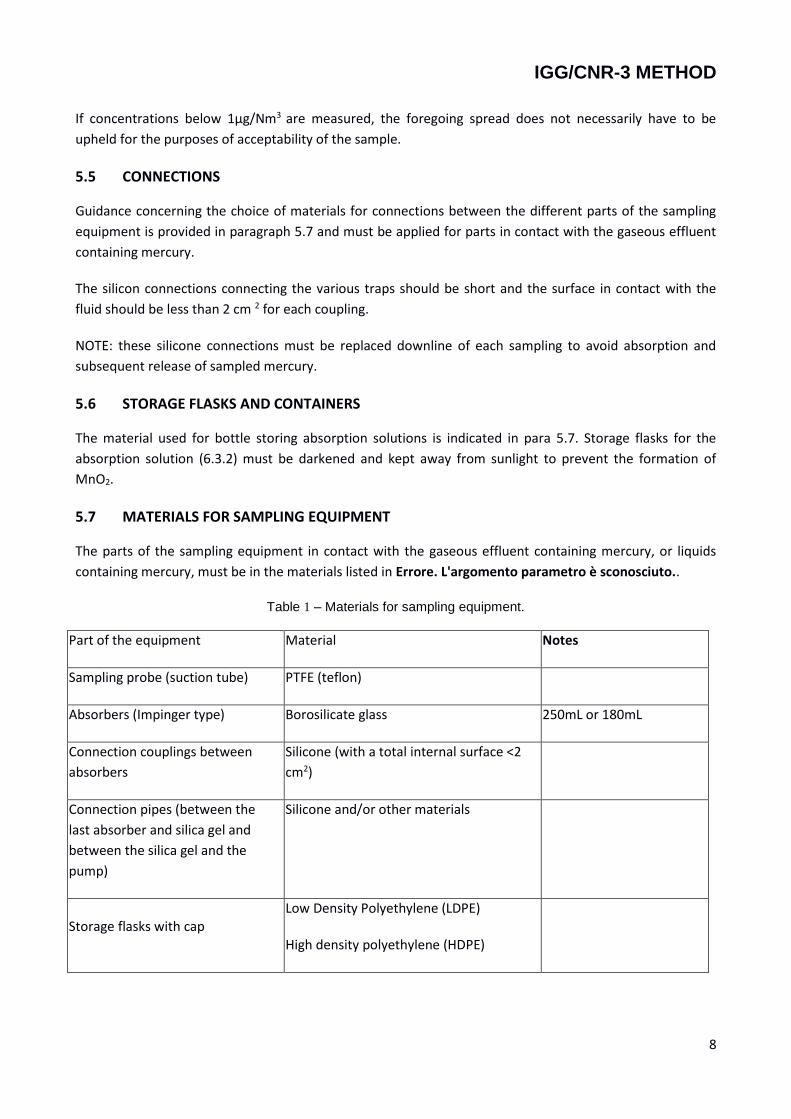
5.7 MATERIALS FOR SAMPLING EQUIPMENT
The parts of the sampling equipment in contact with the gaseous effluent containing mercury, or liquids
containing mercury, must be in the materials listed in Errore. L'argomento parametro è sconosciuto..
Table 1 – Materials for sampling equipment.
Part of the equipment Material Notes
Sampling probe (suction tube) PTFE (teflon)
Absorbers (Impinger type) Borosilicate glass 250mL or 180mL
Connection couplings between
absorbers
Silicone (with a total internal surface <2
cm2)
Connection pipes (between the
last absorber and silica gel and
between the silica gel and the
pump)
Silicone and/or other materials
Storage flasks with cap Low Density Polyethylene (LDPE)
High density polyethylene (HDPE)
IGG/CNR-3 METHOD
9
5.8 SUCTION UNIT
The suction unit must be gas-tight (see 7.3.2) and able extract at least the required gas flow rates from the
duct (5L/min).
Non-return valves can also be used to stop gas flow or backflow caused by low pressure on the sampling
line.
Flowmeters (variable section regulator, plate with orifice, etc.) are strongly recommended in order to
monitor the flow rate. The flowmeters must be subjected to sealing tests and be calibrated at regular
intervals.
5.9 GAS VOLUME MEASURING UNIT
Dry-base flow measurements must be used to measure gas volumes. The requirements for dry-base flow
measurements are as follows:
Presence of a silica gel filter up-line of the pump
Gas-tight pump
Flow adjustment flowmeter
Dry gas volume meter (uncertainty <2% at required flow rate of 5L/min) with absolute associated pressure and temperature measurement (measurement uncertainty <1%).
5.10 ADDITIONAL EQUIPMENT
In order to ensure a constant fixing solution temperature during sampling, the absorbers must be housed in
a water/ice-type thermostat system4
6. REAGENTS
6.1 GENERAL INFORMATION
Only use recognized analytical reagents and distilled or deionized water, all of which with the least possible
mercury content:
Potassium permanganate with low Hg content (≤ 0.05ppm)
Sulphuric acid 95-97% with low Hg content (≤0.005ppm)
Nitric acid 65% with low Hg content
Hydrochloric acid 37% m/m with low Hg content
4 Figure 29-1 EPA 29 method [7]
IGG/CNR-3 METHOD
10
Hydroxylammonium chloride (HONH3CI),
CAUTION Use reagents in accordance with the applicable health and safety regulations.
6.2 REAGENTS FOR PRE-CLEANING OF SAMPLING EQUIPMENT
Use appropriate reagents for pre-cleaning the sampling equipment; see point 7.2 below
6.3 SELECTING ABSORPTION SOLUTIONS
6.3.1 General Information
With reference to the UNI EN 13211:2003 standard, the following solution was chosen to absorb gaseous
mercury: solution of potassium permanganate/sulphuric acid (KMnO4 0.14M / H2SO4 1.08M). In any case,
alternative choices will require the use of high purity reagents for analysis, with the lowest mercury content
among those available.
The maximum absorption solution storage time before sampling is one week.
WARNING: the solutions must be kept in the dark and in flasks fitted with a cap that allows venting of the
gas produced by the decomposition of the solutions themselves (oxygen).
Note: If the sampling line is complete and includes the metal absorption line (fig.2), all the other reagents
used must be characterized by low mercury content.
6.3.2 Absorption solution (KMnO4 0.14M / H2SO4 1.08M)
Slowly add 60mL di H2SO4 (d=1.84kg/L, from 95%m/m to 97%m/m) to 800mL of distilled or deionized water
solution. Weigh 22g of KMnO4, mix gradually with the H2SO4 solution and agitate until the KMnO4 dissolves.
Top up with water to 980mL and mix. Add 2mL of HCl 1M5, top up with water to a volume of 1000mL, mix
and store in a dark place. The solution must be prepared within three days prior to sampling.
6.4 REAGENTS FOR RINSING THE SAMPLING LINE AFTER SAMPLING
6.4.1 Solution of HNO3, 10%m/m
Prepare a solution of HN03 10%m/m by adding 150mL of HNO3 (d=1.41kg/L 65% m/m) to 1L of distilled
water.
5 Add 8.3mL of HCl (d=1.17kg/L at 37%) to 100mL of distilled water

IGG/CNR-3 METHOD
11
6.4.2 Rinsing solution for absorbers.
Use a solution ofhydroxylammonium chloride (HONH3CI) 10%m/m to rinse the absorbers obtained by
dissolving 10.16g of 6.1.5 in 100mL of distilled water.
WARNING: Observe health and safety requirements when using hydroxylammonium chloride.
7. PROCEDURE
7.1 GENERAL REQUIREMENTS
Sampling must be performed at various plunge depths depending on the type of cooling tower:
Natural draught tower - a sampling pipe is of appropriate dimensions (diameter 10mm) is anchored to corridor handrail at representative points of surfaces (circular crowns) with equivalent flow; the average radius of this type of tower is about 19m and the sampling pipe is positioned at about 1.2m, 4.0m, 7.5m and 12.5m from the edge. The collection must be in equal volumes.
Forced draught tower - four sampling and measuring apertures arranged at 90° to each other having two diameters at about 0.90m above the fans of the cell in question. The probe is inserted into the cell and placed in contact with the gas through these above-mentioned apertures. The average radius of these cells is about 4.50 metres and the sampling points are located at about 0.50m, 1.20m, 2.00m and 3.20m from the edge. Whenever possible for this type of tower, two or more adjacent radii of a cell should be analysed.
Sampling must be performed by taking the same volume of gas in all towers specified in the previous points
(approximately 450L, in the event of 4 plunges).
Sampling can be simplified and executed at a single point on the section of the duct in the event of highly
uniform flow when preliminary survey measurements indicate that the following criteria are met:
The standard experimental speed deviation is less than 10% of the average speed value;
Local temperature differences vary by less than 10 °C.
In this case, the sampling point should be positioned at the point where the highest speed was measured.
When sampling is performed in such conditions, at least 0.1 m,. from the wall, this choice must be justified
in the test report and supported by the results of preliminary survey measurements.
7.2 PRE-CLEANING THE EQUIPMENT
All parts of the sampling equipment (Table 1, section 5.7) and reagent storage containers (point 6) that may
come into contact with mercury must be cleaned before taking samples.
Cleaning should be performed using the procedure indicated in Appendix A.2 for the probe and the
connection pipes and in accordance with section A.3 of the same appendix for the absorbers and reagent
storage containers.

IGG/CNR-3 METHOD
12
Check the quality of the washing procedure by keeping the washing solutions used to wash the absorbers in
order to determine the content of mercury whenever necessary in the event that non-conforming
measurements are taken.
It is advisable to prepare washing solutions as required and prepare them fresh at the beginning of each
experimental sequence.
It is advisable to perform a blank sampling of the entire process (paragraph 7.4).
The quality of the reagents used must comply with paragraph 6.1.
7.3 PREPARING AND INSTALLING THE EQUIPMENT
7.3.1 Installing the absorbers
Three absorbers are used: the first is empty to collect the condensing vapour and drift carried; the second
and third contain:
100mL of absorption solution (paragraph 6.3.2) for 250mL absorbers.
60mL of absorption solution (paragraph 6.3.2) for 180mL absorbers.
The above-mentioned absorbers must be installed in a cooler or water/ice bath to ensure a constant
temperature of the sampled gas throughout the sampling procedure.
WARNING Since absorption solutions are highly corrosive, appropriate safety measures must be taken to
prevent personal injury and/or damage to the equipment in the event of breakage or leaks affecting the
absorbers.
7.3.2 Seal tests
It is advisable to perform a sealing test before each sampling. The sealing test is carried out by sealing the
nozzle and starting up the suction unit. Once the minimum pressure has been reached, the leak flow rate
must be less than 2% of the rated sampling flow rate.
7.3.3 Installing the equipment in the sampling position
Install the assembled and complete sampling equipment in the sampling position on the walkway and place
the sampling probe in the sampling aperture of the cooling tower cell selected for measurements. All
sampling equipment installed on the walkway must comply with applicable safety regulations. Avoid any
unintentional gas flow through the sampling equipment before taking samples if there is low pressure in
the cell. The sampling probe comprises one or more teflon tubes (10mm diameter) secured to a rigid beam
that can be fitted inside the cell through a flanged pipe located about 2m from the walkway. Four flanged
couplings are provided to allow sampling along 4 radii at right angles to each other.
IGG/CNR-3 METHOD
13
7.4 BLANK SAMPLING
In order to check the complete process, blank samples of reagents must be taken as well as absorber
washing samples to ensure an appropriate measurement quality level. It is also advisable to perform a
blank process. If positive results are found higher than the LOQ (Limit of Quantification), the value is
subtracted from the analytical results (in concentration).
7.5 SAMPLING PERFORMANCES
Assemble the equipment and check if there any leaks. Note the readings shown on the gas and ambient
pressure measuring device. Start the sampling pumps, set the sampling rate and extract gaseous effluent
from the duct. Note the temperature and pressure readings shown on the gas measuring device at the
outset and for every plunge.
Take samples in conformity with UNI EN ISO 16911-1:2013 and UNI EN 15259:2008. Three replicas must be
performed in parallel for each sampling session. After the sampling time required, stop extracting the
gaseous effluent. Note the readings shown on the gas measuring device, the ambient pressure and the
temperature of the sampled gas.
If the absorption solution as per paragraph 6.3.2 becomes discoloured during sampling, the sampling itself
is no longer valid.
7.6 DISMANTLING THE EQUIPMENT
7.6.1 Rinse the connection pipes on the first absorber
See Appendix A.2.
7.6.2 Collecting absorption solutions from absorbers
Use new and separate flasks to collect the absorption solution for each labelled and identified absorber.
In order to ensure complete transfer of the sample solution to the storage flasks, apply the following
procedure in 2-3 consecutive steps:
1. Wash the absorbers with 0.5-1mL of the solution as per paragraph 6.4.2 and 1-2mL of the nitric acid solution as per paragraph 6.4.1
2. If absorbers still show traces of absorption solution or the presence of MnO2 (brown traces), repeat the washing with 1-2 ml of nitric acid solution as per paragraph 6.4.1.
The above-mentioned washing solutions must be combined with the corresponding absorption solutions
for subsequent analysis.

IGG/CNR-3 METHOD
14
7.6.3 Rinsing the sampling equipment
For the washing procedure after each measurement, refer to Appendix A.2. The washing solutions as per
paragraph 7.6.1 and this paragraph must be combined stored in labelled, identified bottles for subsequent
analysis.
7.7 SAMPLE STORAGE REQUIREMENTS
Samples in HDPE or LDPE storage flasks should be stored at a temperature of less than 6 °C (refrigerator) in
the dark. The samples should be analysed within two weeks of sampling.
7.8 PRE-TREATMENT PRIOR TO ANALYSIS
7.8.1 General Information
Pre-treatment is required before analysing the various samples. This pre-treatment is described in
paragraphs 7.8.2 and 7.8.3 and thereafter. The concentrations of the reagents required are indicated in the
reference analytical standards UNI EN 1483, EPA 7470, EPA 6010D
7.8.2 Absorption solution
Gradually add the rinse solution as per paragraph 6.4.2 to the entire sample until complete discoloration
occurs, to avoid leaks of gaseous mercury (Hgo) from the reaction vessel prior to analysis. Make sure there
is no MnO2 in the solution or on the walls of the storage container (brown traces) without exceeding the
amount of solution 6.4.2 added until a persistent pink colour of the absorption solution is obtained.
Determine and record the final weight of the solution. Take a sub-sample for analysis and analyse it
immediately. If the analysis is not carried out immediately, stabilize the sample by adding a few drops of
absorption solution 6.3.2 until a pink colour is obtained.
7.8.3 Rinsing solution
It is advisable to determine and record the weight or volume of the line rinsing liquid, the first absorber
(empty) and the interconnecting tubes. Take a sub-sample for analysis and analyse it immediately.
7.9 ANALYSIS
Analysis of the solutions pre-treated in accordance with paragraph 7.8 may be performed using the
following methods:
- UNI EN 1483: “Water quality – Determination of mercury” - EPA 7470A: 1994 “Mercury in liquid waste (manual cold-vapour technique)” - EPA 6010D:2014 “Inductively Coupled Plasma - Atomic Emission Spectrometry” + cold vapours
8. REPORTING THE RESULTS
8.1 TOTAL MERCURY CONTENT
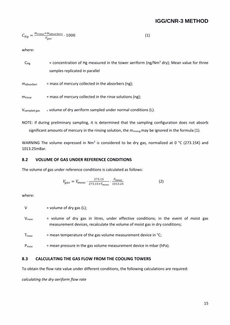
The concentration of Hg in the gaseous effluent is calculated using the following formula:
IGG/CNR-3 METHOD
15
𝐶𝐻𝑔 =𝑚𝑟𝑖𝑛𝑠𝑒+𝑚𝑎𝑏𝑠𝑜𝑟𝑏𝑒𝑟𝑠
𝑉𝑔𝑎𝑠⋅ 1000 (1)
where:
CHg = concentration of Hg measured in the tower aeriform (ng/Nm3 dry); Mean value for three
samples replicated in parallel
mabsorberi = mass of mercury collected in the absorbers (ng);
mrinse = mass of mercury collected in the rinse solutions (ng);
Vsampled gas = volume of dry aeriform sampled under normal conditions (L).
NOTE: if during preliminary sampling, it is determined that the sampling configuration does not absorb
significant amounts of mercury in the rinsing solution, the mrinsing may be ignored in the formula (1).
WARNING The volume expressed in Nm3 is considered to be dry gas, normalized at 0 °C (273.15K) and
1013.25mBar.
8.2 VOLUME OF GAS UNDER REFERENCE CONDITIONS
The volume of gas under reference conditions is calculated as follows:
𝑉𝑔𝑎𝑠 = 𝑉𝑚𝑒𝑎𝑠 ⋅273.15
273.15+𝑇𝑚𝑒𝑎𝑠⋅𝑃𝑚𝑒𝑎𝑠
1013.25 (2)
where:
V = volume of dry gas (L);
Vmeas = volume of dry gas in litres, under effective conditions; in the event of moist gas
measurement devices, recalculate the volume of moist gas in dry conditions;
Tmeas = mean temperature of the gas volume measurement device in °C;
Pmeas = mean pressure in the gas volume measurement device in mbar (hPa).
8.3 CALCULATING THE GAS FLOW FROM THE COOLING TOWERS
To obtain the flow rate value under different conditions, the following calculations are required:
calculating the dry aeriform flow rate

IGG/CNR-3 METHOD
16
𝑄dry =𝑄moist⋅(𝑃amb−𝑃𝐻2𝑂)
𝑃amb (3)
calculating the dry aeriform flow rate under normal conditions
QNdry =𝑃amb⋅𝑄dry
1013,25⋅(𝑇tower+273,15)⋅ 273,15 (4)
calculating the moist aeriform flow rate under normal conditions
QNmoist =𝑃amb⋅𝑄moist
1013,25⋅(𝑇tower+273,15)⋅ 273,15 (5)
Where:
Qdry = tower flow rate - dry aeriform (m3/h)
Qmoist = measured flow rate of the tower - moist aeriform (m3/h)
Pamb = atmospheric pressure at the time of sampling (mbar)
PH2O = water vapour tension at sampling point (mbar)
Ttower = temperature of the tower at the sampling point (°C)
QNdry = flow rate of the tower - dry aeriform under normal conditions (Nm3/h)
QNmoist = flow rate of the tower - moist aeriform under normal conditions (Nm3/h)
8.4 ACCEPTABLE OF REPLICATIONS
See appendix B
8.5 PERFORMANCE CHARACTERISTICS Statistical tests were carried out in collaboration between CNR, Arpat and Enel Green Power in order to
validate this modification to the European standard. These inter-calibration tests made it possible to
identify reference values for the quantification of:
- Lower detection limit estimated at 20 ng/Nm3;
- standard experimental deviation equal to 105 ng/Nm3 for a mean concentration of 310 ng/Nm3.
9. TEST REPORT
The test report must contain at least the following information:
a) reference to this method;
b) reference to the sampling report

IGG/CNR-3 METHOD
17
c) identification and number of sample(s);
d) description of plant and process;
e) plant operating conditions;
f) position of sampling points;
g) number of sampling points and identification of the sampled cell;
h) sampling time;
i) sampling volume(s);
j) type of absorbers;
k) total content of mercury as concentration in mass;
Certain information may be recorded in the sampling report referenced by the test report.

IGG/CNR-3 METHOD
18
APPENDIX A: SAMPLING EQUIPMENT CLEANING PROCEDURE
A.1 General Information
Cleaning must be carried out in the laboratory in accordance with good laboratory practice. This appendix
provides a number of options for cleaning equipment, absorbers and vials.
A.2 Sampling line
After each measurement, wash the sampling line, connection pipes and the first absorber (empty) with a
solution of HNO3 as per paragraph 6.4.1.
WARNING The amount of mercury present in the wash solution can be used to calculate the concentration
of mercury in the aeriform from the cooling towers. If preliminary sampling indicate that this level does not
absorb detectable amounts of mercury, the solution in question may be ignored.
A.3 Absorbers and storage containers for reagents
The washing procedure for absorbers and reagent storage containers can be divided into 5 consecutive
steps:
1. Pre-wash with 50mL of HNO3 solution as per paragraph 6.4.1, agitating for about 5 minutes. 2. Rinse with distilled water 3. Wash with 50mL of absorption solution as per paragraph 6.3.2, agitating for about 10 minutes. 4. When storing cleaning solutions in P.E. bottles, make sure to identify the air-locks and their washing
(for possible analytical checks). 5. Rinse the absorbers with 2mL of rinse solution as per paragraph 6.4.2
The containers must be new. The material of the sample storage bottles (PE) must not be contaminated
with mercury.

IGG/CNR-3 METHOD
19
APPENDIX B: ACCEPTABLE OF REPLICATED DATA (THREE REPLICATIONS IN PARALLEL)
Once the acceptability of an individual sample is assessed in accordance with paragraph 5.4 of this method,
the consistency of the values obtained from three replications can be verified. The most appropriate
statistical method for identifying any abnormal data in the three replications is the one based on the use of
the 99% Confidence Interval (CI) defined in advance on the basis of a study involving 6 replications of an
emission at an average concentration of 310ng / Nm3 performed by ARPAT.
CALCULATING THE 99% CONFIDENCE INTERVAL (CI) BY MEANS OF A PREPARATORY STUDY
The following formulas were used to define the range of acceptability:
𝐼𝐶99 = 𝑡99 ⋅𝑠
√𝑛 eq. 1
Where:
IC99 - 99% confidence interval calculated through 6 replications
t99 - Student t (α 0.01; n. 6 tests)
s - standard experimental deviation for the 6 replications
𝑠 = √∑ (𝑥𝑖−�̅�)
2𝑛1
𝑛−1 eq. 2
𝑥𝑖 is the i-nth measurement
x̅ is the arithmetic mean of the measurements
n is the number of measurements performed
CI99% is given by the following formula:
𝐼𝐶99% =𝐼𝐶99
�̅�100 eq. 3
The following table (B.1) lists the measurements made by Arpat and ENEL at a geothermal power plant
during the preliminary study to calculate the 99% confidence interval (CI)
IGG/CNR-3 METHOD
20
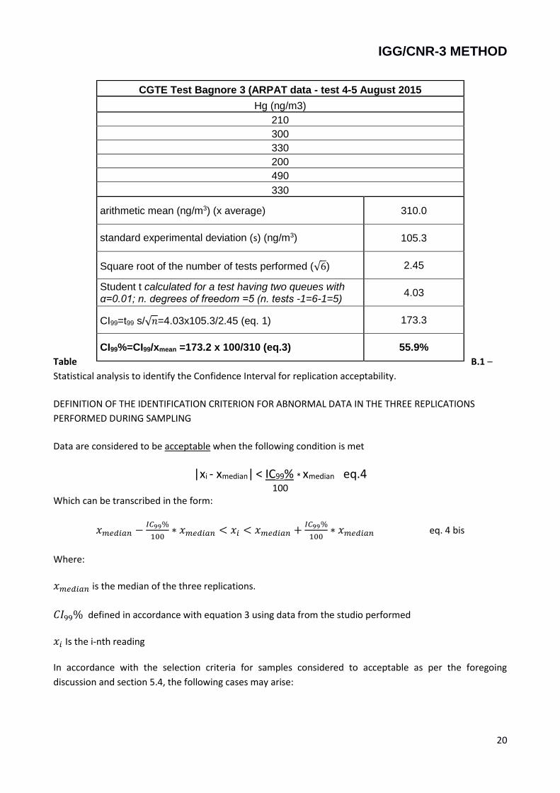
Table B.1 –
Statistical analysis to identify the Confidence Interval for replication acceptability.
DEFINITION OF THE IDENTIFICATION CRITERION FOR ABNORMAL DATA IN THE THREE REPLICATIONS
PERFORMED DURING SAMPLING
Data are considered to be acceptable when the following condition is met
|xi - xmedian| < IC99% * xmedian eq.4
100 Which can be transcribed in the form:
𝑥𝑚𝑒𝑑𝑖𝑎𝑛 −𝐼𝐶99%
100∗ 𝑥𝑚𝑒𝑑𝑖𝑎𝑛 < 𝑥𝑖 < 𝑥𝑚𝑒𝑑𝑖𝑎𝑛 +
𝐼𝐶99%
100∗ 𝑥𝑚𝑒𝑑𝑖𝑎𝑛 eq. 4 bis
Where:
𝑥𝑚𝑒𝑑𝑖𝑎𝑛 is the median of the three replications.
𝐶𝐼99% defined in accordance with equation 3 using data from the studio performed
𝑥𝑖 Is the i-nth reading
In accordance with the selection criteria for samples considered to acceptable as per the foregoing
discussion and section 5.4, the following cases may arise:
CGTE Test Bagnore 3 (ARPAT data - test 4-5 August 2015
Hg (ng/m3)
210
300
330
200
490
330
arithmetic mean (ng/m3) (x average) 310.0
standard experimental deviation (s) (ng/m3) 105.3
Square root of the number of tests performed (√6) 2.45
Student t calculated for a test having two queues with α=0.01; n. degrees of freedom =5 (n. tests -1=6-1=5)
4.03
CI99=t99 s/√𝑛=4.03x105.3/2.45 (eq. 1) 173.3
CI99%=CI99/xmean =173.2 x 100/310 (eq.3) 55.9%
IGG/CNR-3 METHOD
21
Table B.1 lists the measurements taken and the values of the CI 99% confidence interval calculated on the
basis of measurements taken by Arpatat the Enel Green Power geothermal power plant Bagnore 3.
Table B.1 – Statistical analysis to identify the Confidence Interval for replication acceptability.
The results obtained from the three replications carried out in the sampling stage must be evaluated in
order to identify any outliers using the following condition:
In the light of the data obtained, equation (4) becomes:
|𝑥𝑖 − 𝑥𝑚𝑒𝑑𝑖𝑎𝑛| < 0.559 ∗ 𝑥𝑚𝑒𝑑𝑖𝑎𝑛 data acceptability condition
This is the acceptability condition for values found in the field.
Ed. Note :the median was considered rather than the mean median because the median is a statistically
more robust parameter; moreover, if the mean had been used, a combination might have occurred
whereby none of the three samples would be acceptable, thereby invalidating the entire sampling process.
On the basis of the selection criteria for samples considered to acceptable as per the foregoing discussion
and section 5.4, the following cases may arise:
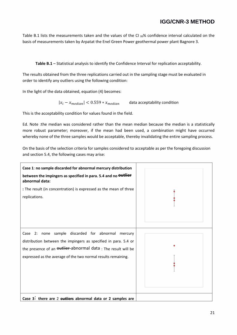
Case 1: no sample discarded for abnormal mercury distribution
between the impingers as specified in para. 5.4 and no outlier abnormal data:
: The result (in concentration) is expressed as the mean of three
replications.
Case 2: none sample discarded for abnormal mercury
distribution between the impingers as specified in para. 5.4 or
the presence of an outlier abnormal data : The result will be
expressed as the average of the two normal results remaining.
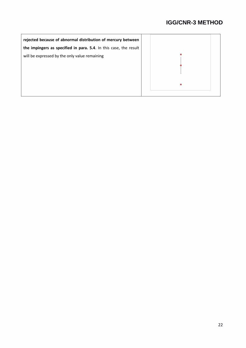
Case 3: there are 2 outliers abnormal data or 2 samples are
IGG/CNR-3 METHOD
22
rejected because of abnormal distribution of mercury between
the impingers as specified in para. 5.4. In this case, the result
will be expressed by the only value remaining