rx2 installation guide with ce update - catlog.net · rx2 installation guide with ce update...
TRANSCRIPT

1 © 2011 Flex Radio Systems. All rights reserved.
RX2 INSTALLATION GUIDE WITH CE
UPDATE Revised: August 15 2011
2 © 2011 Flex Radio Systems. All rights reserved.
RX2 Installation Guide Congratulations on your purchase of a second receiver (RX2) for the FLEX-5000. This will allow you to enjoy the wonderful world of diversity reception and SO2R in a single box.
You will need the following tools to complete the installation:
1. T-20 Torx driver 2. #1 and #2 Phillips screwdriver 3. 3/16” or smaller Flat blade screwdriver 4. 1/4” Hex Nut driver or a Pair of pliers 5. Side or wire cutters 6. Multimeter
The following steps will assist you in the installation and setup of the second receiver.
Before you start the installation of RX2, be sure to UNPLUG the power cord from the radio. NOT doing so can
cause serious damage to the radio and void your warranty!
Prerequisites for Installing the RX2
The RX2 is designated as a user or field installable upgrade only if the FLEX-VU5K (V/U module) is NOT previously
installed. If a FLEX-VU5K is installed in your FLEX-5000, then you must return it to an authorized FlexRadio Systems
Service Center for installation. Installation charges are applicable.
Before starting, remember to observe proper ESD (electrostatic discharge) procedures before attempting the
installation of the FLEX-5000 RX2 in order to prevent damage that may occur from static charges that can build up
on your body or work surfaces. This is especially a concern during the winter months or in climates where the
relative humidity can be very low.
Remove the FLEX-5000 from the Operating Position
a. Turn off the Power to the FLEX-5000 and remove the power connector and all other connecting cables. b. Place the FLEX-5000 on a flat, well lit working surface.
3 © 2011 Flex Radio Systems. All rights reserved.
Preparing the FLEX-5000 for RX2 Installation
Remove the Side Panels.
In addition to the instructions below, you may refer to the KB article, How to Remove and Install the FLEX-5000A Top and Side Panels as a supplementary resource for removing the covers of the FLEX-5000A. http://kc.flex-radio.com/KnowledgebaseArticle50382.aspx)
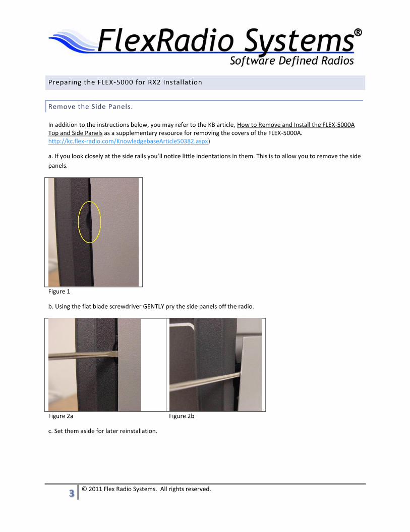
a. If you look closely at the side rails you’ll notice little indentations in them. This is to allow you to remove the side
panels.
Figure 1
b. Using the flat blade screwdriver GENTLY pry the side panels off the radio.
Figure 2a Figure 2b
c. Set them aside for later reinstallation.
4 © 2011 Flex Radio Systems. All rights reserved.
Remove the Top and Bottom Panels.
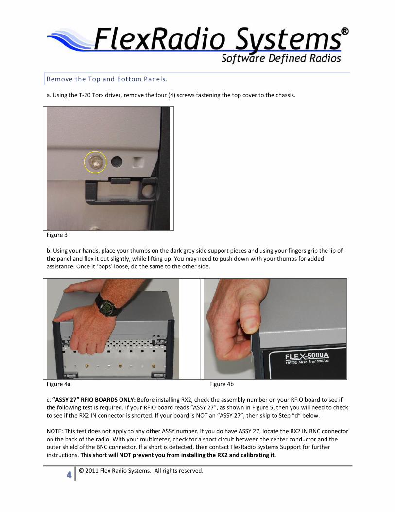
a. Using the T-20 Torx driver, remove the four (4) screws fastening the top cover to the chassis.
Figure 3 b. Using your hands, place your thumbs on the dark grey side support pieces and using your fingers grip the lip of the panel and flex it out slightly, while lifting up. You may need to push down with your thumbs for added assistance. Once it ‘pops’ loose, do the same to the other side.
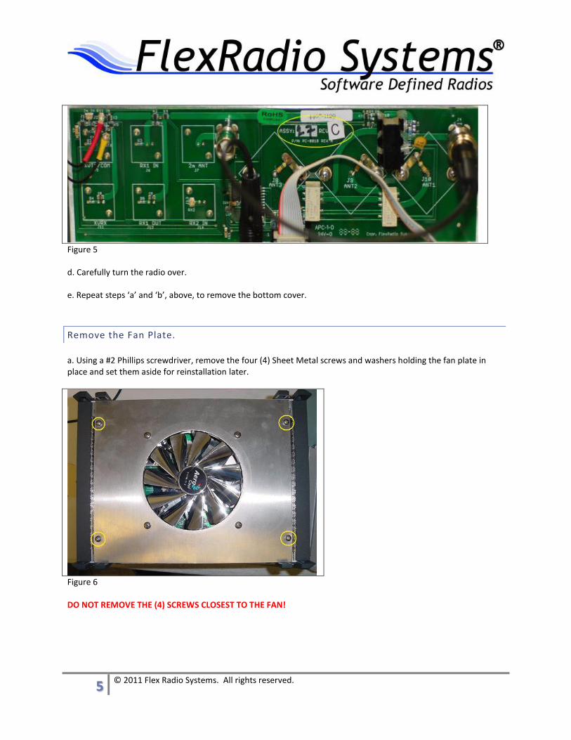
Figure 4a Figure 4b c. “ASSY 27” RFIO BOARDS ONLY: Before installing RX2, check the assembly number on your RFIO board to see if the following test is required. If your RFIO board reads “ASSY 27”, as shown in Figure 5, then you will need to check to see if the RX2 IN connector is shorted. If your board is NOT an “ASSY 27”, then skip to Step “d” below. NOTE: This test does not apply to any other ASSY number. If you do have ASSY 27, locate the RX2 IN BNC connector on the back of the radio. With your multimeter, check for a short circuit between the center conductor and the outer shield of the BNC connector. If a short is detected, then contact FlexRadio Systems Support for further instructions. This short will NOT prevent you from installing the RX2 and calibrating it.
5 © 2011 Flex Radio Systems. All rights reserved.
Figure 5 d. Carefully turn the radio over. e. Repeat steps ‘a’ and ‘b’, above, to remove the bottom cover.
Remove the Fan Plate.
a. Using a #2 Phillips screwdriver, remove the four (4) Sheet Metal screws and washers holding the fan plate in place and set them aside for reinstallation later.
Figure 6 DO NOT REMOVE THE (4) SCREWS CLOSEST TO THE FAN!
6 © 2011 Flex Radio Systems. All rights reserved.
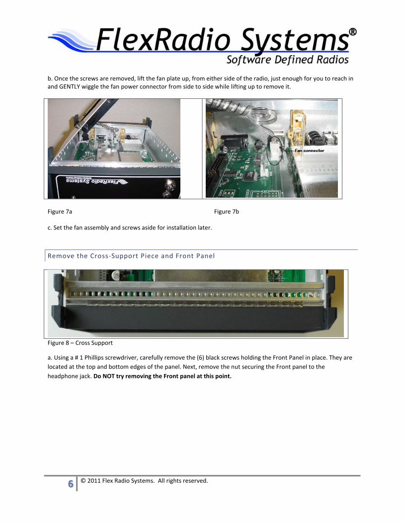
b. Once the screws are removed, lift the fan plate up, from either side of the radio, just enough for you to reach in and GENTLY wiggle the fan power connector from side to side while lifting up to remove it.
Figure 7a Figure 7b c. Set the fan assembly and screws aside for installation later.
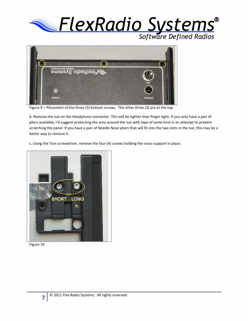
Remove the Cross-Support Piece and Front Panel
Figure 8 – Cross Support
a. Using a # 1 Phillips screwdriver, carefully remove the (6) black screws holding the Front Panel in place. They are
located at the top and bottom edges of the panel. Next, remove the nut securing the Front panel to the
headphone jack. Do NOT try removing the Front panel at this point.
7 © 2011 Flex Radio Systems. All rights reserved.
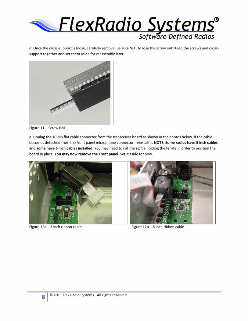
Figure 9 – Placement of the three (3) bottom screws. The other three (3) are at the top
b. Remove the nut on the Headphone connector. This will be tighter than finger tight. If you only have a pair of
pliers available, I’d suggest protecting the area around the nut with tape of some kind in an attempt to prevent
scratching the panel. If you have a pair of Needle Nose pliers that will fit into the two slots in the nut, this may be a
better way to remove it.
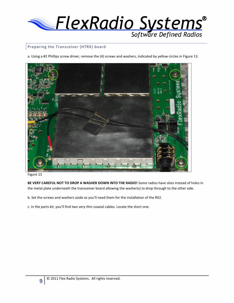
c. Using the Torx screwdriver, remove the four (4) screws holding the cross-support in place.
Figure 10
8 © 2011 Flex Radio Systems. All rights reserved.
d. Once the cross-support is loose, carefully remove. Be sure NOT to lose the screw rail! Keep the screws and cross-
support together and set them aside for reassembly later.
Figure 11 – Screw Rail
e. Unplug the 10-pin flat cable connector from the transceiver board as shown in the photos below. If the cable
becomes detached from the front panel microphone connector, reinstall it. NOTE: Some radios have 3 inch cables
and some have 6 inch cables installed. You may need to cut the zip tie holding the ferrite in order to position the
board in place. You may now remove the Front panel. Set it aside for now.
Figure 12a – 3 inch ribbon cable Figure 12b – 6 inch ribbon cable
9 © 2011 Flex Radio Systems. All rights reserved.
Preparing the Transceiver (HTRX) board
a. Using a #2 Phillips screw driver, remove the (4) screws and washers, indicated by yellow circles in Figure 13.
Figure 13
BE VERY CAREFUL NOT TO DROP A WASHER DOWN INTO THE RADIO! Some radios have slots instead of holes in
the metal plate underneath the transceiver board allowing the washer(s) to drop through to the other side.
b. Set the screws and washers aside as you’ll need them for the installation of the RX2.
c. In the parts kit, you’ll find two very thin coaxial cables. Locate the short one.
10 © 2011 Flex Radio Systems. All rights reserved.
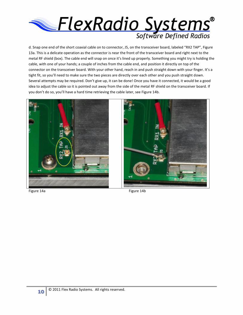
d. Snap one end of the short coaxial cable on to connector, J5, on the transceiver board, labeled “RX2 TAP”, Figure
13a. This is a delicate operation as the connector is near the front of the transceiver board and right next to the
metal RF shield (box). The cable end will snap on once it’s lined up properly. Something you might try is holding the
cable, with one of your hands; a couple of inches from the cable end, and position it directly on top of the
connector on the transceiver board. With your other hand, reach in and push straight down with your finger. It’s a
tight fit, so you’ll need to make sure the two pieces are directly over each other and you push straight down.
Several attempts may be required. Don’t give up, it can be done! Once you have it connected, it would be a good
idea to adjust the cable so it is pointed out away from the side of the metal RF shield on the transceiver board. If
you don’t do so, you’ll have a hard time retrieving the cable later, see Figure 14b.
Figure 14a Figure 14b

11 © 2011 Flex Radio Systems. All rights reserved.
Installing the RX2 in the FLEX-5000
Install the RX2 Board
a. In the parts kit, you’ll find four (4) standoffs, four (4) flat washers and four (4) internal tooth lock washers. Install
the flat washer, internal tooth washer and standoff in the four (4) mounting holes where you removed the four (4)
screws. Refer to Figure 15 for assembly details.
Figure 15
b. Carefully align the four (4) mounting holes on the RX2 with the four (4) standoffs you installed on the transceiver
board.
c. Install the screw/washer stack, you removed from the transceiver board earlier, through the RX2 into the
standoffs. Make sure the flat washer goes on first, then the internal tooth washer, then the screw. Tighten snugly
but do not over tighten.
Install RX2 RF and Control Cables.
a. Attach the other end of the short coaxial cable, which you connected to J5 “RX2 TAP” on the transceiver board,
to the connector J6 “RX2 TAP” on the RX2 board. It’s located in the same place as on the transceiver board. See
Figure 16 below.
12 © 2011 Flex Radio Systems. All rights reserved.
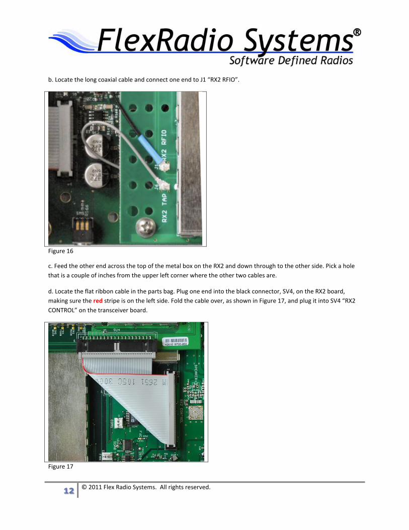
b. Locate the long coaxial cable and connect one end to J1 “RX2 RFIO”.
Figure 16
c. Feed the other end across the top of the metal box on the RX2 and down through to the other side. Pick a hole
that is a couple of inches from the upper left corner where the other two cables are.
d. Locate the flat ribbon cable in the parts bag. Plug one end into the black connector, SV4, on the RX2 board,
making sure the red stripe is on the left side. Fold the cable over, as shown in Figure 17, and plug it into SV4 “RX2
CONTROL” on the transceiver board.
Figure 17
13 © 2011 Flex Radio Systems. All rights reserved.
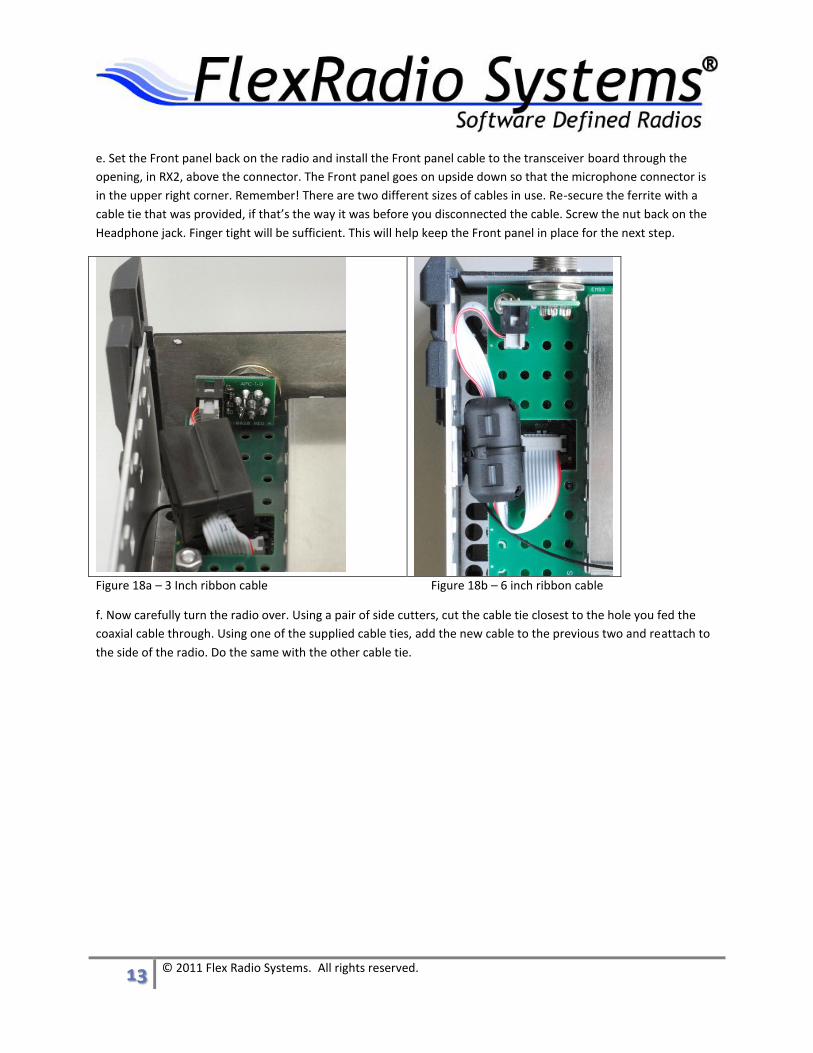
e. Set the Front panel back on the radio and install the Front panel cable to the transceiver board through the
opening, in RX2, above the connector. The Front panel goes on upside down so that the microphone connector is
in the upper right corner. Remember! There are two different sizes of cables in use. Re-secure the ferrite with a
cable tie that was provided, if that’s the way it was before you disconnected the cable. Screw the nut back on the
Headphone jack. Finger tight will be sufficient. This will help keep the Front panel in place for the next step.
Figure 18a – 3 Inch ribbon cable Figure 18b – 6 inch ribbon cable
f. Now carefully turn the radio over. Using a pair of side cutters, cut the cable tie closest to the hole you fed the
coaxial cable through. Using one of the supplied cable ties, add the new cable to the previous two and reattach to
the side of the radio. Do the same with the other cable tie.

14 © 2011 Flex Radio Systems. All rights reserved.
g. Find the loose end of the long coaxial cable you fed through from the other side, and connect it to the RX2
connector on the HRFIO board on the rear panel as shown in the photos below. Note that there are two versions
of the HRFIO board that have a slight difference in the RX2 connector location. It might make things easier if you
temporarily removed the BNC connection in front of the HRFIO card. Once you have the coaxial connector
connected, be sure to reinstall the BNC connector! Failure to do so will result in High SWR and NO power out.
Figure 19a – HRFIO 27 Figure 19b – HRFIO 34
15 © 2011 Flex Radio Systems. All rights reserved.
Install Reassemble the FLEX-5000
NOTE: The installation of finger stock is not required for FLEX-5000 owners in the United States where CE
compliance is not required. For radios that do not need CE compliance, please ignore the instructions below
that are applicable to the installation of finger stock. All other re-assembly steps are applicable.
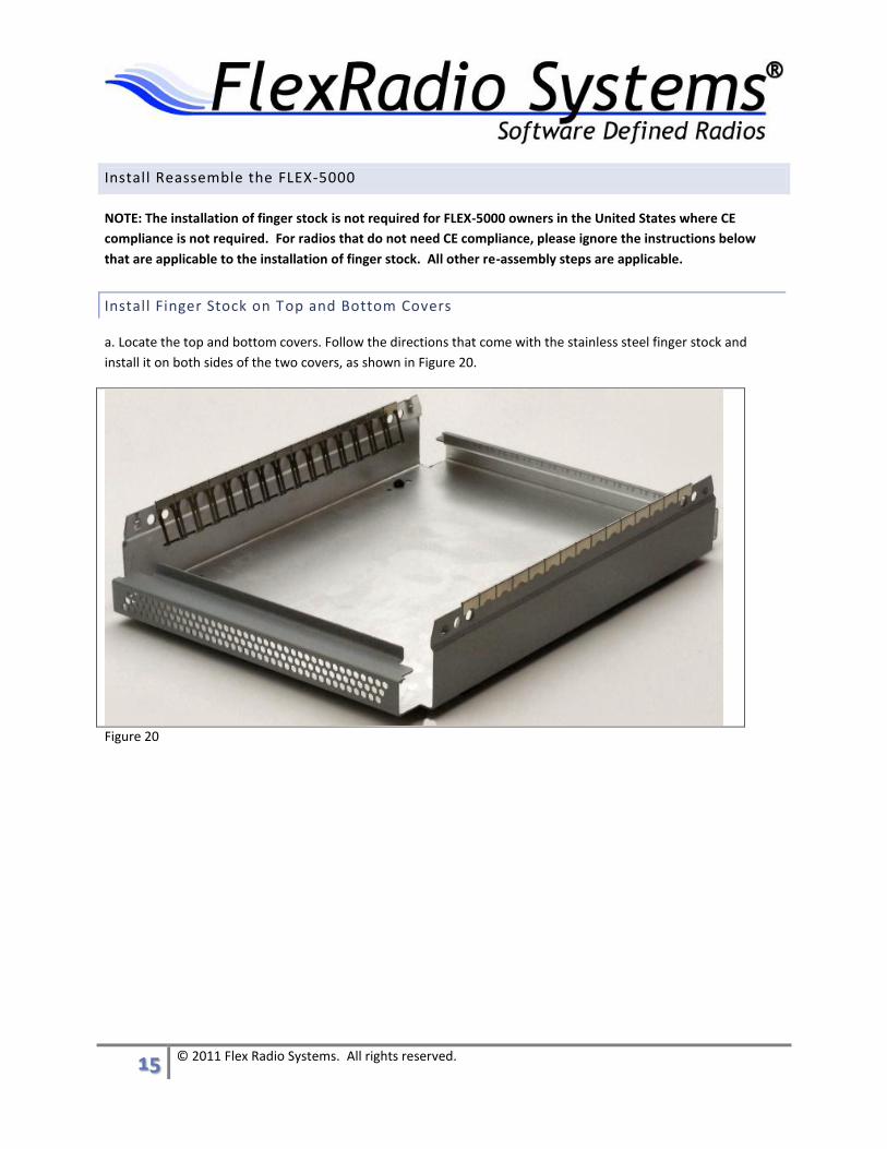
Install Finger Stock on Top and Bottom Covers
a. Locate the top and bottom covers. Follow the directions that come with the stainless steel finger stock and
install it on both sides of the two covers, as shown in Figure 20.
Figure 20

16 © 2011 Flex Radio Systems. All rights reserved.
Remove the Side Support Pieces
a. Looking at the front of the radio, remove the two side support pieces. As shown in Figure 21, remove the LONG
screw closest to the front of the radio. Leave the short screw in place. Do this to the top and bottom of both sides.
Set the pieces aside.
Figure 21
b. Loosely install (3) of the black screws, to the top of the Front panel, to help hold it in place. Refer to Figure 9
above.
c. Carefully turn the radio over.
Install the cross-support.
a. Set the cross-support in place as shown in Figure 8 above.
b. Install the short screws as noted in Figure 21 above.
Install the Front Panel
a. Install the other three (3) black screws to hold the Front panel in place. Lightly tighten all six (6) black screws.
17 © 2011 Flex Radio Systems. All rights reserved.
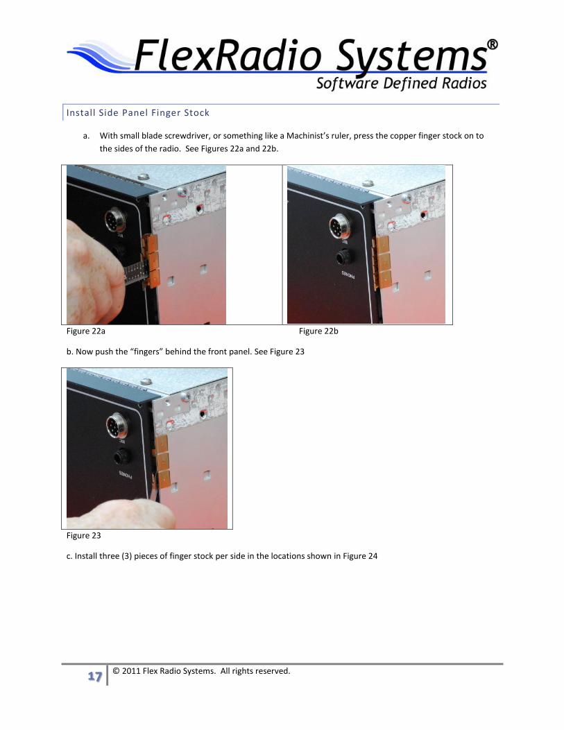
Install Side Panel Finger Stock
a. With small blade screwdriver, or something like a Machinist’s ruler, press the copper finger stock on to
the sides of the radio. See Figures 22a and 22b.
Figure 22a Figure 22b
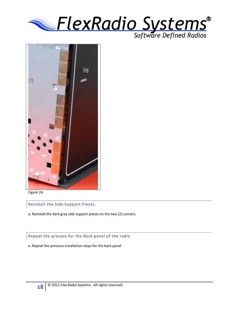
b. Now push the “fingers” behind the front panel. See Figure 23
Figure 23
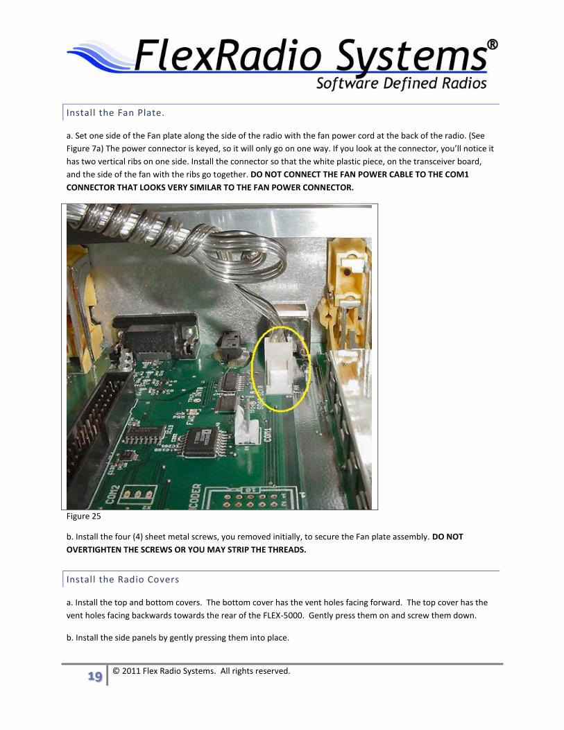
c. Install three (3) pieces of finger stock per side in the locations shown in Figure 24
18 © 2011 Flex Radio Systems. All rights reserved.
Figure 24
Reinstall the Side Support P ieces.
a. Reinstall the dark gray side support pieces on the two (2) corners.
Repeat the process for the Back panel of the radio
a. Repeat the previous installation steps for the back panel
19 © 2011 Flex Radio Systems. All rights reserved.
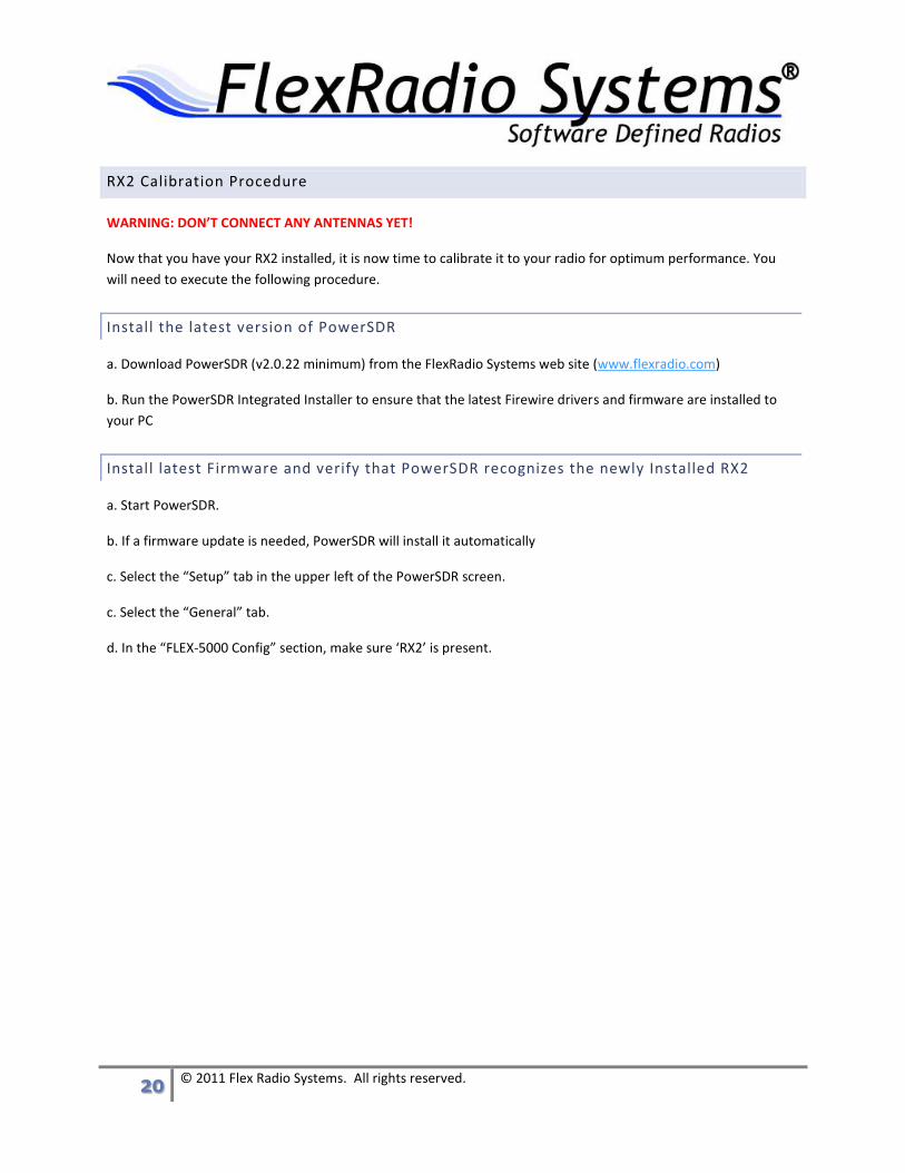
Install the Fan Plate.
a. Set one side of the Fan plate along the side of the radio with the fan power cord at the back of the radio. (See
Figure 7a) The power connector is keyed, so it will only go on one way. If you look at the connector, you’ll notice it
has two vertical ribs on one side. Install the connector so that the white plastic piece, on the transceiver board,
and the side of the fan with the ribs go together. DO NOT CONNECT THE FAN POWER CABLE TO THE COM1
CONNECTOR THAT LOOKS VERY SIMILAR TO THE FAN POWER CONNECTOR.
Figure 25
b. Install the four (4) sheet metal screws, you removed initially, to secure the Fan plate assembly. DO NOT
OVERTIGHTEN THE SCREWS OR YOU MAY STRIP THE THREADS.
Install the Radio Covers
a. Install the top and bottom covers. The bottom cover has the vent holes facing forward. The top cover has the
vent holes facing backwards towards the rear of the FLEX-5000. Gently press them on and screw them down.
b. Install the side panels by gently pressing them into place.
20 © 2011 Flex Radio Systems. All rights reserved.
RX2 Calibration Procedure
WARNING: DON’T CONNECT ANY ANTENNAS YET!
Now that you have your RX2 installed, it is now time to calibrate it to your radio for optimum performance. You
will need to execute the following procedure.
Install the latest version of PowerSDR
a. Download PowerSDR (v2.0.22 minimum) from the FlexRadio Systems web site (www.flexradio.com)
b. Run the PowerSDR Integrated Installer to ensure that the latest Firewire drivers and firmware are installed to
your PC
Install latest Firmware and verify that PowerSDR recognizes the newly Installed RX2
a. Start PowerSDR.
b. If a firmware update is needed, PowerSDR will install it automatically
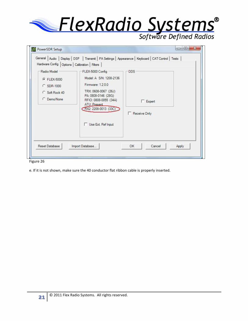
c. Select the “Setup” tab in the upper left of the PowerSDR screen.
c. Select the “General” tab.
d. In the “FLEX-5000 Config” section, make sure ‘RX2’ is present.
21 © 2011 Flex Radio Systems. All rights reserved.
Figure 26
e. If it is not shown, make sure the 40 conductor flat ribbon cable is properly inserted.

22 © 2011 Flex Radio Systems. All rights reserved.
Calibrate the RX2 module
a. Make sure PowerSDR is running (the Start button clicked)
b. Press ‘CTRL+SHIFT+R’ to bring up the RX2 Calibration screen.
c. In the section entitled “Tests”, click on the “None” box.
Figure 27
d. Now click on the box entitled “Run Selected”. This will start the calibration process and optimize it for your
radio.
Figure 28
23 © 2011 Flex Radio Systems. All rights reserved.
e. Wait for the calibrations routines to complete
f. Close the RX2 Calibration / Tests window.
g. Your RX2 is now ready to use.