rothenberger worldwide robull 2
TRANSCRIPT

Germany Headquarters
Australia
Austria
Belgium
Brazil
Bulgaria
China
Czech Republic
Denmark
France
Greece
Hungary
India
Ireland
ROTHENBERGER AGIndustriestrasse 7 • D-65779 Kelkheim/GermanyTel. + 49 (0) 61 95 / 800 - 1 • Fax + 49 (0) 61 95 / 7 44 [email protected] • www.rothenberger.comROTHENBERGER Produktion GmbHLilienthalstrasse 71 - 87 • D-37235 Hessisch-LichtenauTel. + 49 (0) 56 02 / 93 94 - 0 • Fax + 49 (0) 56 02 / 93 94 36ROTHENBERGER Werkzeuge GmbHIndustriestrasse 7 • D-65779 Kelkheim/GermanyTel. + 49 (0) 61 95 / 800 - 1 • Fax + 49 (0) 61 95 / 7 44 [email protected]
ROTHENBERGER Australia Pty. Ltd.Unit 12 • 5 Hudson Avenue • Castle Hill • N.S.W. 2154Tel. + 61 2 / 98 99 75 77 • Fax + 61 2 / 98 99 76 [email protected]
ROTHENBERGER Werkzeuge- und Maschinen Handelsgesellschaft m.b.H.Gewerbeparkstrasse 9 • A-5081 Anif near SalzburgTel. + 43 (0) 62 46 / 7 20 91-45 • Fax + 43 (0) 62 46 / 7 20 91 [email protected] • www.rothenberger.at
ROTHENBERGER Benelux bvbaAntwerpsesteenweg 59 • B-2630 AartselaarTel. + 32 (0) 3 / 8 77 22 77 • Fax + 32 (0) 3 / 8 77 03 [email protected]
ROTHENBERGER do Brasil Ltda.Rua marinho de Carvalho, No. 72 - Vila Marina09921-005 Diadema - Sao Paulo - BrazilTel. + 55 11 / 40 44 47-48 • Fax + 55 11 / 40 44 [email protected] • www.rothenberger.com.br
ROTHENBERGER Bulgaria GmbHBoul. Sitniakovo 79 • BG-1111 SofiaTel. + 35 9 / 2 9 46 14 59 • Fax + 35 9 / 2 9 46 12 [email protected] • www.rothenberger.bg
SHANGHAI ROTHENBERGER I/E CO., LTDNo. 199 Jiugan Road, Sijing Town Songjiang District, Shanghai, (201601) ChinaTel. + 86 / 21 57 61 76 88 • 0086 / 21 5761 7959Fax + 86 / 21 57 62 60 62 • [email protected]
ROTHENBERGER CZ, nárˇadí a stroje, spol. s.r.o.Vinohradská 100 (1710) • CZ-130 00 Praha 3Tel. + 42 02 / 71 73 01 83 • Fax + 42 02 / 67 31 01 [email protected] • www.rothenberger.cz ROTHENBERGER Scandinavia A/SFåborgvej 8 • DK-9220 Aalborg ØstTel. + 45 98 / 15 75 66 • Fax + 45 98 / 15 68 [email protected]
ROTHENBERGER France S.A.24, rue des Drapiers, BP 45033 • F-57071 Metz Cedex 3Tel. + 33 3 / 87 74 92 92 • Fax + 33 3 / 87 74 94 [email protected]
ROTHENBERGER Hellas S.A.249 Syngrou Avenue • GR-171 22 Nea Smyrni, AthensTel. + 30 210 / 94 07 302 • Fax + 30 210 / 94 07 [email protected]
ROTHENBERGER Hungary Kft.Gubacsi út 26 • H-1097 BudapestTel. + 36 1 / 3 47 - 50 40 • Fax + 36 1 / 3 47 - 50 [email protected]
ROTHENBERGER India Private LimitedB-1/D-5,Ground Floor Mohan Cooperative Industrial EstateMathura Road, New Delhi 110044Tel. + 91 11 / 51 69 90 40, 51 69 90 50 • Fax + 91 11 / 51 69 90 [email protected]
ROTHENBERGER Ireland Ltd.Bay N. 119, Shannon Industrial EstateIRL-Shannon, Co. ClareTel. + 35 3 61 / 47 21 88 • Fax + 35 3 61 / 47 24 [email protected]
ROTHENBERGER WorldwideItaly
Mexico
Netherlands
Poland
Portugal
Singapore
South Africa
Spain
Switzerland
Turkey
UK
USA
Russia
ROTHENBERGER Italiana s.r.l.Via G. Reiss Romoli 17 • I-20019 Settimo MilaneseTel. + 39 02 / 33 50 12 12 • Fax + 39 02 / 33 50 [email protected] • www.rothenberger.it
Rothenberger S.A. Sucursal MéxicoBosques de Duraznos No. 69-1006Bosques de las Lomas • México D.F. 11700Tel. + 52 / 55 85 89 - 39 48 ext 21/22Fax + 52 / 55 85 89 - 57 70 ext 11
ROTHENBERGER Nederland bvPostbus 45 • NL-5120 AA RijenTel. + 31 (0) 1 61 / 29 35 79 • Fax + 31 (0) 1 61 / 29 39 [email protected] • www.rothenberger.nl
ROTHENBERGER Polska Sp.z.o.o.ul. Cyklamenów 1 • PL-04-798 WarszawaTel. + 48 22 / 6 12 77 01 • Fax + 48 22 / 6 12 72 [email protected] • www.rothenberger.pl
SUPER-EGO TOOLS FERRAMENTAS, S.A.Apartado 62 - 2894-909 Alcochete - PORTUGALTel. + 3 51 / 9 12 21 80 80 • Fax + 3 51 / 2 26 00 40 [email protected]
ROTHENBERGER TOOLS (FE) PTE LTD147 Thyrwhitt RoadSingapore 207561Tel. + 65 / 6296 - 2031 • Fax + 65 / 6296 - 4031www.rothenberger.com.sg
ROTHENBERGER-TOOLS SA (PTY) Ltd.P.O. Box 4360 • Edenvale 1610165 Vanderbijl Street, Meadowdale GermistonGauteng (Johannesburg), South AfricaTel. + 27 11 / 3 72 96 33 • Fax + 27 11 / 3 72 96 [email protected]
ROTHENBERGER S.A.Ctra. Durango-Elorrio, Km 2 • E-48220 Abadiano (Vizcaya)(P.O. Box) 117 • E-48200 Durango (Vizcaya)Tel. + 34 94 / 6 21 01 00 • Fax + 34 94 / 6 21 01 [email protected] • www.rothenberger.es
ROTHENBERGER Schweiz AGHerostr. 9 • CH-8048 ZürichTel. + 41 / 14 01 08 00 • Fax + 41 / 1 4 01 06 [email protected]
ROTHENBERGER Tes. Alet ve Mak. San. Tic. Ltd. Sti Poyraz Sok. No: 20/3 - Detay Is MerkeziTR-34722 Kadiköy-IstanbulTel. + 90 / 216 449 24 85 pbx • Fax + 90 / 216 449 24 85 [email protected]
ROTHENBERGER UK Limited2, Kingsthorne Park, Henson WayKettering • GB-Northants NN16 8PXTel. + 44 15 36 / 31 03 00 • Fax + 44 15 36 / 31 06 [email protected]
ROTHENBERGER USA LLC4455 Boeing Drive; USA-Rockford, IL 61109Tel. + 1 / 8 15 3 97 70 70 • Fax + 1 / 8 15 3 97 82 89www.rothenberger-usa.com
ROTHENBERGER USA Inc.Western Regional Office • USA-955 Monterey Pass RoadMonterey Park, CA 91754Tel. + 13 23 / 2 68 13 81 • Fax + 13 23 / 26 04 97
ROTHENBERGER Agency
OLMAX2-d Verkhny Mikhailovsky pr-d, 9 build.2 115419 MoscowTel. +7/09 57 92 59 44 • Fax +7/09 57 92 59 [email protected] • www.olmax.ru
Service Hotline +49 (0) 61 95-99 52-12
www.rothenberger.com
ROBULL 2"Bedienungsanleitung
Instructions for useInstruction d'utilisation
Instrucciones de usoIstruzioni d'uso
Instruções de uso
www.rothenberger.com/manuals
5.7950X
5.7966X
5.7961X
5.7969X
5.7973X
5.7972X
9992
079
02.
08

1. Allgemeine Merkmale . . . 2
2.Inbetriebnahme und Einsatz der Rohrbiegesystem (aufklappbare Variante) . . . . . . . . . . . . . . . . . . . . . . . . 2
3. Instandhaltung und Wartung . . . . . . . . . . . . . . . . . . . . . . . . . . . . . . . . . . . . . . . . . . . . . . . . . . . . . . . . . . . . . . 3
4. Mögliche Störungen und deren Behebung . . . . . . . . . . . . . . . . . . . . . . . . . . . . . . . . . . . . . . . . . . . . . . . . . . . 3
4.1 Wenn der Kolben nicht vorläuft . . . . . . . . . . . . . . . . . . . . . . . . . . . . . . . . . . . . . . . . . . . . . . . . . . . . . . . 3
4.2 Wenn der Kolben nur im lastfreien Zustand vorläuft, nicht jedoch unter Last . . . . . . . . . . . . . . . . . 3
4.3 Wenn der Kolben zwar vorläuft, jedoch vor Hubende anhält . . . . . . . . . . . . . . . . . . . . . . . . . . . . . . . 3
4.4 Wenn der Kolben bei jedem Pumpvorgang zunächst vor- und danach zurückläuft: . . . . . . . . . . . . 3
4.5 Wenn der Kolben problemlos unter Last vorläuft, jedoch der Hebel abrupt zurückschlägt: . . . . . . 3
5. Anweisungshandbuch . . . 4-5
444 5
Mit den rothenberger Rohrbiegesystemen können galvanisierte oder schwarze Eisenrohre oder den Einsatz von Innendrückformen kaltgebogen werden, wenn sie folgenden Rohrqualitäten entsprechen:
Eisenrohr EN 10255 Mittlere und Schwere Baureihe
Mit diesen Rohrbiegesystem können Winkel zwischen 0º und 180º gebogen werden, wobei 90º direkt und die übrigen Winkel in mehreren Kurven anzufertigen sind.
Die Hydraulikpumpe ist der typische von Hand (oder Elektrisch) betätigte Monoblock und wird hydraulisch bedingt automatisch zurückgeführt.
Hauptmerkmale:
Arbeitsleistung: 8 Tn (manuell)Höchsthub: 270 mm.Kolbendurchmesser: 34 mm.Durchmesser des Pumpenkolbens: 16 mm (manuell) y 10 mm (elektro).Auszuwechselndes Ölvolumen: 850 cc.
••••
•
Zu verwendendes Öl: Tipo ISO 32 o similar.
Führungsplatten im vorderen Flansch der Hydraulikpumpe einsetzen und mit den Stiften befestigen.
Seitenformen an der unteren Biegeform entsprechend des Durchmessers des zu biegenden Rohrgröße in Stellung bringen.
Am Ende des Kolbens die dem Rohrdurchmesser entsprechende Biegeform anbringen, das Rohr auflegen und die obere Biegeform aufsetzen.
Falls das zu biegende Rohr eine Schweißnaht aufweist, sollte das Rohr mit der Schweißnaht entweder nach oben oder nach unten aufgelegt werden.
Vor Inbetriebnahme des Rohrbiegesystems ist der Hydraulikkreislauf zu entlüften. Hierfür den Rücklaufschlüssel öffnen und mehrmals mit dem Hebel pumpen oder mit dem Schalter.
•
1.
2.
3.
4.
5.
Allgemeine Merkmale1.Inbetriebnahme und Einsatz der Rohrbiegesystem (aufklappbare Variante)
2.
Stellen Sie sicher, dass das Rücklaufventil gut verschlossen und der Behälterstopfen offen ist.
Anschließend kann mit der Betätigung des Pumpenhebels begonnen werden oder mit dem Schalter.
Sobald der Biegevorgang beendet ist, erfolgt der Rücklauf des Kolbens durch Lösen des Rücklaufventils, das sich seitlich am Verteiler befindet.
Regelmäßig den Ölstand prüfen.
Das Nachfüllen von Öl unter besonderer Sorgfalt beim Filtern vornehmen, um die Eindringen von Fremdkörpern zu vermeiden. Die Ölstandsprüfung erfolgt durch Anheben des vorderen Gerätateils um etwa 45º. Hierbei muß sichergestellt sein, daß das Öl bis an die Markierung der Ölbefüllungsöffnung reicht.
6.
7.
8.
Sobald die Befüllung vorgenommen wurde, die Hand-Hydraulikpumpe in fast senkrechte Schrägstellung bringen (Kolben nach oben), das Rücklaufventil öffnen und den Hebel der Pumpe betätigen, bis ein einwandfreies Ansaugen festgestellt wird. Die Hand-Hydraulikpumpe kurz in dieser Stellung belassen und die Ansaugung in waagrechter Position überprüfen.
Sollte Öl nachzufüllen sein, sollte dies mit einem erstklassigen Hydrauliköl erfolgen und niemals mit Bremsflüssigkeit. Berücksichtigen Sie dabei, dass das Gerät bei Überfüllung nicht betriebsfähig ist. Füllen Sie daher etwa 70% des Behälterfüllvermögens (1250 cm3) nach.
Behälterstopfen im Transportfall schließen
Instandhaltung und Wartung3.
Mögliche Störungen und deren Behebung4.
Ursache LösungWenn der Kolben nicht vorläuft
Es fehlt Öl Überprüfen Sie den Ölstand
Rücklaufventil nicht richtig geschlossen Rücklaufventil schließen
Im System befindet sich Luft (Pumpe)Rücklauf öffnen und den Hebel der Pumpe bis zum Entlüften betätigen; das Gerät hierfür mit dem Kolben nach oben stellen, damit das Öl zum Verteiler abläuft
Wenn der Kolben nur im lastfreien Zustand vorläuft, nicht jedoch unter Last
Rücklaufventil nicht richtig geschlossen Rücklaufventil schließen
Fremdkörper im AnsaugventilAnsaugventil zerlegen und gut reinigen; wobei der Kolben vorher zurückzuführen ist
Wenn der Kolben zwar vorläuft, jedoch vor Hubende anhält
Sehr niedriger Ölstand Öl nachfüllen
Behälterstopfen ist geschlossen Behälterstopfen öffnen
Wenn der Kolben bei jedem Pumpvorgang zunächst vor- und danach zurückläuft
Fremdkörper im Ausblasventil oder Luft in den Leitungen
Zylinder senkrecht stellen und den Kolben zuvor zurückführen. Ausblasventil zerlegen und reinigen.
Fremdkörper im Ansaugventil Ansaugventil zerlegen und reinigen
Wenn der Kolben problemlos unter Last vorläuft, jedoch der Hebel abrupt zurückschlägt
Fremdkörper im Rückschlagventil Rückschlagventil zerlegen und reinigen
BEDIENUNGSANLEITUNG
BEDIENUNGSANLEITUNGINDEX

666 7
106
108
2107
6
105
8
9
10
11
16
51
50
48
46
45
44
4342
41
40
39
31
22
29
61
3233
34
63
62
60
13
14
15
2120
47
12
30
38
56
59
58
49
Art. Nr. Beschreibung Nº Art. Nr. Nº Art. Nr.
5.7985 Mit kurzem Radius 3/8” 2 8.4852 46 8.48665.8010 Mit langem Radius 3/8” 6 8.4855 47 8.48855.7986 Mit kurzem Radius 1/2” 8 8.4864 48 8.48855.8011 Mit langem Radius 1/2” 9 8.4858 49 8.48845.7987 Mit kurzem Radius 3/4” 10 8.4859 50 8.48835.8012 Mit langem Radius 3/4” 11 8.4857 51 8.48865.7988 Mit kurzem Radius 1” 12 8.4860 56 77701375.8013 Mit langem Radius 1” 14 8.4849 58 77701185.7989 Mit kurzem Radius 1.1/4” 15 8.4850 59 77701325.8014 Mit langem Radius 1.1/4” 20 8.4871 60 77701315.7990 Mit kurzem Radius 1.1/2” 21 8.4880 61 77701335.8015 Mit langem Radius 1.1/2” 22 8.4879 62 21101345.7991 Mit kurzem Radius 2” 23 8.4877 63 21100195.8016 Mit langem Radius 2” 28 8.4627 106 77700205.7981 Biegerahmen 2”, offen 29 8.4878 105 77700245.7979 Steckbolzen 30 8.4882 107 77700255.7982 Seitenformen rechts (für Biegerahmen, offen) 31 8.4874 108 77700265.7983 Seitenformen links (für Biegerahmen, offen) 32 8.48755.7352 Dreibein-Untergestell 33 8.4873
R 5.8185 Hydraulik-öl (1 Liter) 35 8.48615.8002 Biegerahmen 2”, aufklappbar 38 8.48715.7979 Steckbolzen 39 8.48725.8004 Seitenformen rechts 40 8.78705.8004 Seitenformen links 42 8.48815.7950 Hand-Hydraulikpumpe 43 8.4867
Art. Nr. Beschreibung Nº Art. Nº Nº Art. Nº
5.7985 Mit kurzem Radius 3/8” 2 8.4852 76 8.42415.8010 Mit langem Radius 3/8” 6 8.4855 77 8.42325.7986 Mit kurzem Radius 1/2” 8 8.4864 78 77701355.8011 Mit langem Radius 1/2” 9 8.4858 79 77701295.7987 Mit kurzem Radius 3/4” 10 8.4859 80 77701285.8012 Mit langem Radius 3/4” 11 8.4857 82 77701275.7988 Mit kurzem Radius 1” 12 8.4860 83 77701325.8013 Mit langem Radius 1” 14 8.4849 84 77701315.7989 Mit kurzem Radius 1.1/4” 15 8.4850 85 77701335.8014 Mit langem Radius 1.1/4” 20 8.4871 86 77701345.7990 Mit kurzem Radius 1.1/2” 21 8.4880 87 21100195.8015 Mit langem Radius 1.1/2” 22 8.4879 88 77701135.7991 Mit kurzem Radius 2” 23 8.4877 89 77701185.8016 Mit langem Radius 2” 29 8.4878 90 77701385.7981 Biegerahmen 2”, offen 30 8.4882 91 77701145.7979 Steckbolzen 31 8.4874 92 77701435.7982 Seitenformen rechts (für Biegerahmen, offen) 32 8.4875 93 77701425.7983 Seitenformen links (für Biegerahmen, offen) 33 8.4873 100 77700205.7352 Dreibein-Untergestell 35 8.4861 102 7770024
R 5.8185 Hydraulik-öl (1 Liter) 38 8.4871 103 77700255.8002 Biegerahmen 2”, aufklappbar 39 8.4872 104 77700265.7979 Steckbolzen 40 8.78705.8004 Seitenformen rechts 72 8.42425.8004 Seitenformen links 73 8.42495.7968 Elektro-Hydraulikpumpe 230V 74 8.4250
54
37
38
39
40
29
28
20
19
21
22
29
35
2324
2526
27
12
11
16
15
14
1310
9
87
85
51
50
49
48
58
59
60
61 62
63
47
46
64
65
66
67
70
69
70
71
72
74
73
75
77
76
92
42
93
44
45
55
56
57
17
48
49
88
91
85
87
86
8483
31
3233
3430
51
101
102
8
103
2
104
100
90
89
ANWEISUNGSHANDBUCH ANWEISUNGSHANDBUCH
elektromanuell

1. General characteristics . . . 6
2. Starting up and using the two-plate pipe bender . . . . . . . . . . . . . . . . . . . . . . . . . . . . . . . . . . . . . . . . . . . . . 6
3. Training and maintenance 7
4. Troubleshooting . . . . . . . . . 7
4.1 The piston fails to advance . . . . . . . . . . . . . . . . . . . . . . . . . . . . . . . . . . . . . . . . . . . . . . . . . . . . . . . . . . . 7
4.2 The piston advances only in the absence of load . . . . . . . . . . . . . . . . . . . . . . . . . . . . . . . . . . . . . . . . . 7
4.3 The piston stops before reaching the end of its stroke . . . . . . . . . . . . . . . . . . . . . . . . . . . . . . . . . . . . 7
4.4 The piston advances and returns with each pump stroke . . . . . . . . . . . . . . . . . . . . . . . . . . . . . . . . . . 7
4.5 The piston advances well under load but the lever returns suddenly . . . . . . . . . . . . . . . . . . . . . . . . . 7
5. Exploded drawing . . . . . . 8-9
888 9
With the rothenberger pipe bender you can cold bend galvanized or black steel pipes of the following types, without filling, and without reamers on the inside:
Steel Pipe EN 10255 Medium and heavy series
The angles we can effect with these benders range from 0º to 180º. A right angle can be made directly, while others can be effected with several curves.
These angles can be in different planes. The equipment could be hand operated or electrically, with automatic, piston return.
Its main features are:
Nominal power: 8 TnMaximum travel: 270 mm.Piston diameter: 34 mm.Pump piston diameter: 16 mm (hand operated) y 10 mm (electric).Volume of top-up oil: 850 cc.
••••
•
Oil to be used: ISO 32 or similar.
Fit the guide plates to the front flange and secure them with pins.
Fit the diabolos to the lower plate, in the position corresponding to the size of the pipe to be bent. At the same time fit the diabolo in position in accordance with the size of the pipe.
At the end of the piston, fit the former corresponding to the size of the pipe that it is desired to bend. Place the pipe in position and put down the upper plate.
In the event that the pipe to be bent is welded, the weld beam should be placed either in the upper or lower side position.
Before starting to use the pipe bender, release any pressure there may be in the valve system of the hydraulic circuit. Do this by opening the return cock and pumping several times with the lever or switch on the motor.
•
1.
2.
3.
4.
5.
General characteristics1.Starting up and using the two-plate pipe bender
2.
Make sure the return valve is well closed, and the tank plug open
You can then begin to operate the pump lever or switch on the motor.
When the bend has been finished, return the piston by loosening the return valve on the side of the distributor.
Check oil level at regular intervals. When topping up, be especially sure to filter the oil so that it is free of extraneous matter. Check its level by lifting the front part of the unit about 45º and looking in. The oil should reach the level of the hole used for loading it in.
6.
7.
8.
When the oil has been topped up, fit the unit in inclined position, i.e. almost vertical, and with the piston upward. Open the return valve and work the pump with the lever until suction is as it should be. After a short space of time with the position unchanged, and when suction is satisfactory, fit in horizontal working position.
In the event that it is necessary to top up, use a high-quality hydraulic oil. Never use brake fluid. Bear in mind that excess of oil will render the equipment inoperative. Accordingly fill to about 70% of tank capacity (1250 cc), first removing the cap.
Close the tank plug for transportation
Training and maintenance3.
Troubleshooting4.
Cause SolutionThe piston fails to advance
Insufficient oil Check oil level
Return valve not closed Close return valve
Air in the system (pump)
Open the return valve and operate the pump lever until the air is released. To do this, position the unit with the piston upward, so that the oil will descend to the distributor
The piston advances only in the absence of load
Return valve is poorly closed Close the return valve
There is a foreign body in the intake valveDisassemble the intake valve and clean it thoroughly, first having made the piston return
The piston stops before reaching the end of its stroke
Very low oil level Top up the oil
Tank plug closed Open the tank plug
The piston advances and returns with each pump stroke
Foreign body in the output valve, or air in the pipesPosition the cylinder vertically, first having made the cylinder return. Take apart the output valve and clean it.
Foreign body in the intake valveTake apart the intake valve and clean it, first having made the piston return.
The piston advances well under load but the lever returns suddenly
Foreign body in the check valveRemove the check valve, disassemble it, and clean it, first having made the piston return.
INSTRUCTIONS FOR USE
INSTRUCTIONS FOR USEINDEX

101010 11
106
108
2107
6
105
8
9
10
11
16
51
50
48
46
45
44
4342
41
40
39
31
22
29
61
3233
34
63
62
60
13
14
15
2120
47
12
30
38
56
59
58
49
Code Item Nº Art. Nº Nº Art. Nº
5.7985 Short radius 3/8” wafer 2 8.4852 46 8.48665.8010 Long radius 3/8” wafer 6 8.4855 47 8.48855.7986 Short radius 1/2” wafer 8 8.4864 48 8.48855.8011 Long radius 1/2” wafer 9 8.4858 49 8.48845.7987 Short radius 3/4” wafer 10 8.4859 50 8.48835.8012 Long radius 3/4” wafer 11 8.4857 51 8.48865.7988 Short radius 1” wafer 12 8.4860 56 77701375.8013 Long radius 1” wafer 14 8.4849 58 77701185.7989 Short radius 1.1/4” wafer 15 8.4850 59 77701325.8014 Long radius 1.1/4” wafer 20 8.4871 60 77701315.7990 Short radius 1.1/2” wafer 21 8.4880 61 77701335.8015 Long radius 1.1/2” wafer 22 8.4879 62 21101345.7991 Short radius 2” wafer 23 8.4877 63 21100195.8016 Long radius 2” wafer 28 8.4627 106 77700205.7981 2” single plate 29 8.4878 105 77700245.7979 Fastening bolt 30 8.4882 107 77700255.7982 Right diabolo. Single plate 31 8.4874 108 77700265.7983 Left diabolo. Single plate 32 8.48755.7352 Tripod 33 8.4873
R 5.8185 Hydraulic Oil (1 Litre) 35 8.48615.8002 2” double plate 38 8.48715.7979 Fastening bolt 39 8.48725.8004 2” double plate right diabolo 40 8.78705.8004 2” double plate left diabolo 42 8.48815.7950 Hand-operated hydraulic pump 43 8.4867
Code Item Nº Art. Nº Nº Art. Nº
5.7985 Short radius 3/8” wafer 2 8.4852 76 8.42415.8010 Long radius 3/8” wafer 6 8.4855 77 8.42325.7986 Short radius 1/2” wafer 8 8.4864 78 77701355.8011 Long radius 1/2” wafer 9 8.4858 79 77701295.7987 Short radius 3/4” wafer 10 8.4859 80 77701285.8012 Long radius 3/4” wafer 11 8.4857 82 77701275.7988 Short radius 1” wafer 12 8.4860 83 77701325.8013 Long radius 1” wafer 14 8.4849 84 77701315.7989 Short radius 1.1/4” wafer 15 8.4850 85 77701335.8014 Long radius 1.1/4” wafer 20 8.4871 86 77701345.7990 Short radius 1.1/2” wafer 21 8.4880 87 21100195.8015 Long radius 1.1/2” wafer 22 8.4879 88 77701135.7991 Short radius 2” wafer 23 8.4877 89 77701185.8016 Long radius 2” wafer 29 8.4878 90 77701385.7981 2” single plate 30 8.4882 91 77701145.7979 Fastening bolt 31 8.4874 92 77701435.7982 Right diabolo. Single plate 32 8.4875 93 77701425.7983 Left diabolo. Single plate 33 8.4873 100 77700205.7352 Tripod 35 8.4861 102 7770024
R 5.8185 Hydraulic Oil (1 Litre) 38 8.4871 103 77700255.8002 2” double plate 39 8.4872 104 77700265.7979 Fastening bolt 40 8.78705.8004 2” double plate right diabolo 72 8.42425.8004 2” double plate left diabolo 73 8.42495.7968 Electro hydraulic pump 230 V 74 8.4250
54
37
38
39
40
29
28
20
19
21
22
29
35
2324
2526
27
12
11
16
15
14
1310
9
87
85
51
50
49
48
58
59
60
61 62
63
47
46
64
65
66
67
70
69
70
71
72
74
73
75
77
76
92
42
93
44
45
55
56
57
17
48
49
88
91
85
87
86
8483
31
3233
3430
51
101
102
8
103
2
104
100
90
89
EXPLODED DRAWING EXPLODED DRAWING
electric hand operated

1. Caracteristiques generales . . . . . . . . . . . . . . . . . . . . . . . . . . . . . . . . . . . . . . . . . . . . . . . . . . . . . . . . . . . . . . . 10
2.Mise en marchet et utilisation de la cintreuse (flasque double) . . . . . . . . . . . . . . . . . . . . . . . . . . . . . . . . . 10
3. Entretient . . . . . . . . . . . . . 11
4. Pannes possibles et solutions . . . . . . . . . . . . . . . . . . . . . . . . . . . . . . . . . . . . . . . . . . . . . . . . . . . . . . . . . . . . . 11
4.1 Le piston n’avance pas . . . . . . . . . . . . . . . . . . . . . . . . . . . . . . . . . . . . . . . . . . . . . . . . . . . . . . . . . . . . . 11
4.2 Le piston n’avance pas en position de travail . . . . . . . . . . . . . . . . . . . . . . . . . . . . . . . . . . . . . . . . . . . 11
4.3 Le piston avance mais s’arrête avant la fin du parcours . . . . . . . . . . . . . . . . . . . . . . . . . . . . . . . . . . . 11
4.4 Le piston avance et recule à chaque coup de pompe . . . . . . . . . . . . . . . . . . . . . . . . . . . . . . . . . . . . . 11
4.5 Le piston avance en position de travail mais le levier recule brusquement . . . . . . . . . . . . . . . . . . 11
5. Liste de pièces de rechange . . . . . . . . . . . . . . . . . . . . . . . . . . . . . . . . . . . . . . . . . . . . . . . . . . . . . . . . . . . . 12-13
121212 13
Avec les cintreuses Rothenberger, il est possible de cintrer à froid et sans aucune déformation des tubes en fer noir ou galvanisé du type:
Tube Fer EN 10255 Série Moyenne et Lourde
Les angles de cintrage sont compris entre 0° et 180°, le cintrage à 90° se faisant directement en 1 seule opération et le reste en plusieures opérations.
Ces angles de cintrage peuvent être sur des plans différents. Vérin monobloc manuel ou électrique avec retour automatique du piston.
Caractéristiques principales:
Puissance de travail: 8 TnParcours: 270 mm.Diamètre du piston: 34 mm.Diamètre du piston pompe: 16 mm (manuelle) y 10 mm (électrique).Volume d’huile à remettre: 850 cc.
••••
•
Type d’huile conseillée: ISO 32.
Placer les flasques guides dans la plaque frontale du vérin et les fixer avec les goupilles.
Placer les diabolos dans leur position corréspondante sur le flasque inférieur selon les mesures des tubes à cintrer.
Emboîter sur le piston la forme corréspondante à la mesure du tube qu’on va cintrer, placer le tube et fermer l’ensemble avec le flasque supérieur.
Si le tube à cintrer a été soudé, placer la soudure perpendiculairement par rapport au-sol.
Avant d’utiliser la cintreuse, il faut d’abbord s’assurer qu’il n’y a pas de l’air dans les système de soupapes du circuit hydraulique. Il faut donc ouvrir la manette de décharge et pomper plusieures fois avec le levier ou mise en marche.
S’assurer que le clapet anti-retour est bien fermé, et
•
1.
2.
3.
4.
5.
6.
Caracteristiques generales1.
Mise en marchet et utilisation de la cintreuse (flasque double)
2.
que le bouchon du réservoir est ouvert
On peut alors commencer à pomper avec le levier ou mise en marche.
Dès que le cintrage est fini, le retour du piston se fait en desserrant la manette de décharge qui est placée sur un côté du distributeur.
Il faut absolument éviter les démontages inutiles et vérifier périodiquement le niveau d’huile. Le remplissage d’huile doit se réaliser en faisant bien attention de filtrer celle-ci pour ne pas introduire des débris. La vérification du niveau d’huile se fait en soulevant de 45° la partie frontale du verin: le niveau d’huile doit atteindre le trou de remplissage du réservoir.
7.
8.
Dès que l’opération de remplissage a été réalisée, placer le vérin en position presque verticale (le piston vers le haut), ouvrir la manette de décharge et pomper jusqu’à ce que l’aspiration soit parfaitement vérifiée. Après un moment dans cette position et vérification de l’aspiration, replacer le vérin en position horizontale de travail.
Au cas où il faudrait remettre de l’huile, utiliser une huile d’application hydraulique de bonne qualité. Ne jamais utiliser de liquide pour freins. Le remplissage doit se faire jusqu’à peu près le 70% de la capacité du réservoir (1.250 cc.). Un éxcés d’huile rend le vérin inopérant.
Fermer le bouchon du réservoir pour le transport
Entretient3.
Pannes possibles et solutions4.
Cause SolutionLe piston n’avance pas
Manque d’huile Vérifier le niveau d’huile
La manette de décharge est mal fermée Fermer la manette de décharge
Il y a de l’air dans le circuit hydrauliqueOuvrir la manette de décharge et pomper en plaçant le vérin avec le piston vers le haut pour que l’huile tombe dans le distributeur
Le piston n’avance pas en position de travail
La manette de décharge est mal fermée Fermer la manette de décharge
Il y a des débris dans la soupape d’aspirationFaire reculer le piston, puis démonter et nettoyer la soupape d’aspiration
Le piston avance mais s’arrête avant la fin du parcours
Le niveau d’huile est en dessous du normal Remettre de l’huile jusqu’à atteindre le niveau souhaitable
Bouchon du réservoir fermé Ouvrir le bouchon du réservoir
Le piston avance et recule à chaque coup de pompe
Il y a des débris dans la soupape d’expulsión, ou de l’air dans le circuit
Faire reculer le piston et placer le cylindre en position verticale, en le faisant reposer sur le distributeur, puis démonter et nettoyer la soupape d’éxpulsion
Il y a des débris dans la soupape d’aspirationFaire reculer le piston, puis démonter et nettoyer la soupape d’aspiration.
Le piston avance en position de travail mais le levier recule brusquement
Il y a des débris dans la soupape de rétentionFaire reculer le piston puis démonter et nettoyer la soupape de rétention
INSTRUCTION D'UTILISATION
INSTRUCTION D'UTILISATIONTABLE DES MATIÈRES

141414 15
106
108
2107
6
105
8
9
10
11
16
51
50
48
46
45
44
4342
41
40
39
31
22
29
61
3233
34
63
62
60
13
14
15
2120
47
12
30
38
56
59
58
49
Código Descripción Nº Art. Nº Nº Art. Nº
5.7985 Forme 3/8” Rayon court. 2 8.4852 46 8.48665.8010 Forme 3/8” Rayon long. 6 8.4855 47 8.48855.7986 Forme 1/2” Rayon court. 8 8.4864 48 8.48855.8011 Forme 1/2” Rayon long. 9 8.4858 49 8.48845.7987 Forme 3/4” Rayon court. 10 8.4859 50 8.48835.8012 Forme 3/4” Rayon long. 11 8.4857 51 8.48865.7988 Forme 1” Rayon court. 12 8.4860 56 77701375.8013 Forme 1” Rayon long. 14 8.4849 58 77701185.7989 Forme 1.1/4” Rayon court. 15 8.4850 59 77701325.8014 Forme 1.1/4” Rayon long. 20 8.4871 60 77701315.7990 Forme 1.1/2” Rayon court. 21 8.4880 61 77701335.8015 Forme 1.1/2” Rayon long. 22 8.4879 62 21101345.7991 Forme 2” Rayon court. 23 8.4877 63 21100195.8016 Forme 2” Rayon long. 28 8.4627 106 77700205.7981 Flasque 2” 29 8.4878 105 77700245.7979 Boulon d’attache. 30 8.4882 107 77700255.7982 Diabolo droit. Monofasque. 31 8.4874 108 77700265.7983 Diabolo gauche. Monofasque. 32 8.48755.7352 Trépied. 33 8.4873
R 5.8185 Huile hydraulique (1 Litre) 35 8.48615.8002 Flasque double 2” 38 8.48715.7979 Boulon d’attache. 39 8.48725.8004 Diabolo droit flasque double 2” 40 8.78705.8004 Diabolo gauche flasque double 2” 42 8.48815.7950 Verin Hydraulique (Manuelle) 43 8.4867
Código Descripción Nº Art. Nº Nº Art. Nº
5.7985 Forme 3/8” Rayon court. 2 8.4852 76 8.42415.8010 Forme 3/8” Rayon long. 6 8.4855 77 8.42325.7986 Forme 1/2” Rayon court. 8 8.4864 78 77701355.8011 Forme 1/2” Rayon long. 9 8.4858 79 77701295.7987 Forme 3/4” Rayon court. 10 8.4859 80 77701285.8012 Forme 3/4” Rayon long. 11 8.4857 82 77701275.7988 Forme 1” Rayon court. 12 8.4860 83 77701325.8013 Forme 1” Rayon long. 14 8.4849 84 77701315.7989 Forme 1.1/4” Rayon court. 15 8.4850 85 77701335.8014 Forme 1.1/4” Rayon long. 20 8.4871 86 77701345.7990 Forme 1.1/2” Rayon court. 21 8.4880 87 21100195.8015 Forme 1.1/2” Rayon long. 22 8.4879 88 77701135.7991 Forme 2” Rayon court. 23 8.4877 89 77701185.8016 Forme 2” Rayon long. 29 8.4878 90 77701385.7981 Flasque 2” 30 8.4882 91 77701145.7979 Boulon d’attache. 31 8.4874 92 77701435.7982 Diabolo droit. Monofasque. 32 8.4875 93 77701425.7983 Diabolo gauche. Monofasque. 33 8.4873 100 77700205.7352 Trépied. 35 8.4861 102 7770024
R 5.8185 Huile hydraulique (1 Litre) 38 8.4871 103 77700255.8002 Flasque double 2” 39 8.4872 104 77700265.7979 Boulon d’attache. 40 8.78705.8004 Diabolo droit flasque double 2” 72 8.42425.8004 Diabolo gauche flasque double 2” 73 8.42495.7968 Électrique Hydraulique 230 V 74 8.4250
54
37
38
39
40
29
28
20
19
21
22
29
35
2324
2526
27
12
11
16
15
14
1310
9
87
85
51
50
49
48
58
59
60
61 62
63
47
46
64
65
66
67
70
69
70
71
72
74
73
75
77
76
92
42
93
44
45
55
56
57
17
48
49
88
91
85
87
86
8483
31
3233
3430
51
101
102
8
103
2
104
100
90
89
LISTE DE PIÈCES DE RECHANGE LISTE DE PIÈCES DE RECHANGE
électriquemanuelle
1. Caracteristicas generales 14
2. Puesta en servicio y utilización del curvatubos (placa doble) . . . . . . . . . . . . . . . . . . . . . . . . . . . . . . . . . . . 14
3. Mantenimiento . . . . . . . . 15
4. Posibles fallos y sus solucicones . . . . . . . . . . . . . . . . . . . . . . . . . . . . . . . . . . . . . . . . . . . . . . . . . . . . . . . . . . . 15
4.1 Si el émbolo no avanza . . . . . . . . . . . . . . . . . . . . . . . . . . . . . . . . . . . . . . . . . . . . . . . . . . . . . . . . . . . . . 15
4.2 Si el émbolo avanza en vacío pero no en carga . . . . . . . . . . . . . . . . . . . . . . . . . . . . . . . . . . . . . . . . . 15
4.3 Si el émbolo avanza pero se para antes del fin del curso . . . . . . . . . . . . . . . . . . . . . . . . . . . . . . . . . 15
4.4 Si el émbolo avanza y retrocede a cada golpe de bomba: . . . . . . . . . . . . . . . . . . . . . . . . . . . . . . . . . 15
4.5 Si el émbolo avanza bien en carga pero retrocede bruscamente la palanca: . . . . . . . . . . . . . . . . . . 15
5. Despieces . . . . . . . . . . . 16-17
161616 17
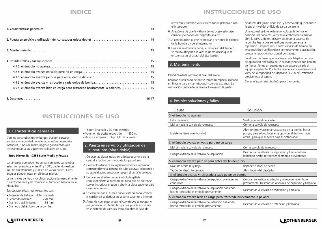
Con los curvatubos rothenberger, pueden curvarse en frio, sin necesidad de rellenar, ni utilizar mandriles interiores, tubos de hierro negro o galvanizado que correspondan a las siguientes calidades de tubo:
Tubo Hierro EN 10255 Serie Media y Pesada
Los ángulos que podemos curvar con estos curvatubos están comprendicos entre 0° y 180°, pudiendo realizar los 90° directamente y el resto en varias curvas. Estos ángulos pueden estar en distintos planos.
La central es del tipo monobloc, accionada manualmente o eléctricamente y de retroceso automático basada en la hidráulica.
Sus características más relevantes son:
Potencia de trabajo: 8 Tn (manual).Recorrido máximo: 270 mm.Diámetro del émbolo: 34 mm.Diámetro del émbolo de la bomba:
••••
16 mm (manual) y 10 mm (eléctrica).Volumen de aceite reposición: 850 cc. Aceite a emplear: Tipo ISO 32 o similar.
Colocar las placas guias en la brida delantera de la central y fijarlos por medio de los pasadores.
Colocar los diábolos en la placa inferior, en la posición correspondiente al tamaño de tubo a curvar, colocando a su vez el diábolo en posición según el tamaño de tubo.
Colocar en el extremo del émbolo la galleta correspondiente al tamaño del tubo que se pretende curvar, introducir el tubo y abatir la placa superior para cerrar el conjunto.
En caso de que el tubo a curvar esté soldado, colocar el cordón de soldadura en la parte superior o inferior.
Antes de comenzar a usar el curvatubos es necesario purgar el circuito hidráulico ya que puede existir aire en el sistema de válvulas. Para ello abra la llave de
••
1.
2.
3.
4.
5.
Caracteristicas generales1.
Puesta en servicio y utilización del curvatubos (placa doble)
2.
retroceso y bombee varias veces con la palanca o con el interruptor.
Asegúrese de que la válvula de retroceso está bien cerrada, y el tapón del depósito abierto.
A continuación puede comenzar a accionar la palanca de la bomba o con el interruptor.
Una vez realizada la curva, el retroceso del émbolo se realiza aflojando la válvula de retroceso que se encuentra en el lateral del distribuidor.
Periódicamente verificar el nivel del aceite.
Realizar el rellenado de aceite teniendo especial cuidado en filtrarlo para evitar introducir cuerpos extraños. La verificación del aceite se realizará elevando la parte
6.
7.
8.
delantera del grupo unos 45°, y observando que el aceite llegue al nivel del orificio de carga de aceite.
Una vez realizado el rellenado, colocar la central en posición inclinada casi vertical (el émbolo hacia arriba), abrir la válvula de retroceso y accionar la palanca de la bomba hasta que se verifique correctamente la aspiración. Después de un corto espacio de tiempo en esta posición y verificándose correctamente la aspiración, colocar en posición horizontal de trabajo.
En el caso de tener que reponer aceite hágalo con uno de aplicación hidráulica de 1ª calidad y nunca con líquido de frenos. Tenga en cuenta que un exceso dejaría el equipo inoperante. Por tanto rellene aproximadamente el 70% de la capacidad del depósito (1.250 cc), retirando previamente el tapón.
Cerrar el tapón del depósito para transporte.
Mantenimiento3.
Posibles soluciones y fallos4.
Causa SoluciónSi el émbolo no avanza
Falta de aceite Verificar el nivel de aceite
Mal cerrada la válvula de retroceso Cerrar la válvula de retroceso
El sistema tiene aire (bomba)Abrir retorno y accionar la palanca de la bomba hasta purgar, para ello colocar el grupo con el émbolo hacia arriba, para que el aceite baje al distribuidor
Si el émbolo avanza en vacío pero no en carga
Mal cerrada la válvula de retroceso Cerrar válvula de retroceso
Cuerpo extraño en la válvula de aspiraciónDesmontar la válvula de aspiración y limpiarla bien, habiendo hecho retroceder el émbolo previamente
Si el émbolo avanza pero se para antes del fin del curso
Nivel de aceite muy bajo Reponer el nivel de aceite
Tapón del depósito cerrado Abrir tapón del depósito
Si el émbolo avanza y retrocede a cada golpe de bomba
Cuerpo extraño en la válvula de expulsión o aire en los conductos
Colocar en vertical el cilindro y retroceder el émbolo previamente. Desmontar la válvula de expulsión y limpiarla.
Cuerpo extraño en la válvula de aspiración habiendo hecho retroceder el émbolo previamente
Desmontar la válvula de aspiración y limpiarla
Si el émbolo avanza bien en carga pero retrocede bruscamente la palanca
Cuerpo extraño en la válvula de retención habiendo hecho retroceder el émbolo previamente
Desmontar la válvula de retención y limpiarla
INSTRUCCIONES DE USO
INSTRUCCIONES DE USOINDICE

181818 19
106
108
2107
6
105
8
9
10
11
16
51
50
48
46
45
44
4342
41
40
39
31
22
29
61
3233
34
63
62
60
13
14
15
2120
47
12
30
38
56
59
58
49
Código Descripción Nº Art. Nº Nº Art. Nº
5.7985 Galleta 3/8” radio corto 2 8.4852 46 8.48665.8010 Galleta 3/8” radio largo 6 8.4855 47 8.48855.7986 Galleta 1/2” radio corto 8 8.4864 48 8.48855.8011 Galleta 1/2” radio largo 9 8.4858 49 8.48845.7987 Galleta 3/4” radio corto 10 8.4859 50 8.48835.8012 Galleta 3/4” radio largo 11 8.4857 51 8.48865.7988 Galleta 1” radio corto 12 8.4860 56 77701375.8013 Galleta 1” radio largo 14 8.4849 58 77701185.7989 Galleta 1.1/4” radio corto 15 8.4850 59 77701325.8014 Galleta 1.1/4” radio largo 20 8.4871 60 77701315.7990 Galleta 1.1/2” radio corto 21 8.4880 61 77701335.8015 Galleta 1.1/2” radio largo 22 8.4879 62 21101345.7991 Galleta 2” radio corto 23 8.4877 63 21100195.8016 Galleta 2” radio largo 28 8.4627 106 77700205.7981 Placa única 2” 29 8.4878 105 77700245.7979 Bulón sujección 30 8.4882 107 77700255.7982 Diábolo derecho. Placa única 31 8.4874 108 77700265.7983 Diábolo izquierdo. Placa única 32 8.48755.7352 Trípode 33 8.4873
R 5.8185 Aceite hidraúlico (1 Litro) 35 8.48615.8002 Placa doble 2” 38 8.48715.7979 Bulón sujección. 39 8.48725.8004 Diábolo derecho placa doble 2” 40 8.78705.8004 Diábolo izquierdo placa doble 2” 42 8.48815.7950 Central hidraúlica manual 43 8.4867
Código Descripción Nº Art. Nº Nº Art. Nº
5.7985 Galleta 3/8” radio corto 2 8.4852 76 8.42415.8010 Galleta 3/8” radio largo 6 8.4855 77 8.42325.7986 Galleta 1/2” radio corto 8 8.4864 78 77701355.8011 Galleta 1/2” radio largo 9 8.4858 79 77701295.7987 Galleta 3/4” radio corto 10 8.4859 80 77701285.8012 Galleta 3/4” radio largo 11 8.4857 82 77701275.7988 Galleta 1” radio corto 12 8.4860 83 77701325.8013 Galleta 1” radio largo 14 8.4849 84 77701315.7989 Galleta 1.1/4” radio corto 15 8.4850 85 77701335.8014 Galleta 1.1/4” radio largo 20 8.4871 86 77701345.7990 Galleta 1.1/2” radio corto 21 8.4880 87 21100195.8015 Galleta 1.1/2” radio largo 22 8.4879 88 77701135.7991 Galleta 2” radio corto 23 8.4877 89 77701185.8016 Galleta 2” radio largo 29 8.4878 90 77701385.7981 Placa única 2” 30 8.4882 91 77701145.7979 Bulón sujección 31 8.4874 92 77701435.7982 Diábolo derecho. Placa única 32 8.4875 93 77701425.7983 Diábolo izquierdo. Placa única 33 8.4873 100 77700205.7352 Trípode 35 8.4861 102 7770024
R 5.8185 Aceite hidraúlico (1 Litro) 38 8.4871 103 77700255.8002 Placa doble 2” 39 8.4872 104 77700265.7979 Bulón sujección. 40 8.78705.8004 Diábolo derecho placa doble 2” 72 8.42425.8004 Diábolo izquierdo placa doble 2” 73 8.42495.7968 Central hidraúlica motorizada 230 V 74 8.4250
54
37
38
39
40
29
28
20
19
21
22
29
35
2324
2526
27
12
11
16
15
14
1310
9
87
85
51
50
49
48
58
59
60
61 62
63
47
46
64
65
66
67
70
69
70
71
72
74
73
75
77
76
92
42
93
44
45
55
56
57
17
48
49
88
91
85
87
86
8483
31
3233
3430
51
101
102
8
103
2
104
100
90
89
DESPIECES DESPIECES
eléctricamanual

1. Caratteristiche generali . 20
2. Messa in servizio ed uso del curvatubi (piastra doppia) . . . . . . . . . . . . . . . . . . . . . . . . . . . . . . . . . . . . . . . 20
3. Manutenzione . . . . . . . . . 21
4. Possibili problemi e le loro soluzioni . . . . . . . . . . . . . . . . . . . . . . . . . . . . . . . . . . . . . . . . . . . . . . . . . . . . . . . 21
4.1 Se il pistone non avanza . . . . . . . . . . . . . . . . . . . . . . . . . . . . . . . . . . . . . . . . . . . . . . . . . . . . . . . . . . . . 21
4.2 Se il pistone avanza a vuoto però non in carico . . . . . . . . . . . . . . . . . . . . . . . . . . . . . . . . . . . . . . . . . 21
4.3 Se il pistone avanza però si ferma prima della fine della corsa . . . . . . . . . . . . . . . . . . . . . . . . . . . . 21
4.4 Se il pistone avanza e retrocede ad ogni colpo di pompa . . . . . . . . . . . . . . . . . . . . . . . . . . . . . . . . 21
4.5 Se il pistone avanza bene in carico però retrocede bruscamente la leva . . . . . . . . . . . . . . . . . . . . . 21
5. Quadro pezzi smontati . . . . . . . . . . . . . . . . . . . . . . . . . . . . . . . . . . . . . . . . . . . . . . . . . . . . . . . . . . . . . . . . 22-23
202020 21
Con i curvatubi Rothenberger, si possono curvare a freddo, senza la necessità di riempire, né di utilizzare mandrini interni, tubi di ferro nero o zincato che corrispondono alle seguenti qualità di tubo:
Tubo Ferro EN 10255 Serie Media e Pesante
Gli angoli che si possono curvare con questi curvatubi sono compresi tra 0° e 180°, potendo realizzare i 90° direttamente ed il resto in varie curve. Questi angoli possono essere su diversi piani.
La centralina è del tipo monobloc, azionata manualmente o elettricamente e a ritorno automatico basata nell’idraulica.
Le sue caratteristiche più rilevanti sono:
Potenza di lavoro: 8 Tn (manuale).Corsa max: 270 mm.Diametro del pistone: 34 mm.Diametro del pistone della pompa:
••••
16 mm (manuale) y 10 mm (elettrica). Volume cambio dell’olio: 850 cc. Olio da impiegare: Tipo ISO 32 o simile.
Collocare le piastre guida sulla flangia anteriore della centralina e fissarle per mezzo delle spine.
Collocare i nottolini sulla piastra inferiore, nella posizione relativa al formato del tubo da curvare, collocando a sua volta il nottolino in posizione secondo il formato del tubo.
Collocare sull’estremità del pistone la matrice relativa al formato del tubo che si vuole curvare, inserire il tubo e ripiegare la piastra superiore per chiudere l’insieme.
Nei casi in cui il tubo da curvare fosse saldato, collocare il cordone di saldatura nella parte superiore o inferiore.
Prima d’iniziare ad usare il curvatubi è necessario spurgare il circuito idraulico poiché ci può essere dell’aria nel sistema a valvole. Per far ciò aprire la chiave di ritorno e pompare varie volte con la leva o con l’interruttore.
••
1.
2.
3.
4.
5.
Caratteristiche generali1.
Messa in servizio ed uso del curvatubi (piastra doppia)
2.
Assicurarsi che la valvola di ritorno sia perfettamente chiusa, e il tappo del serbatoio aperto.
Di seguito si può iniziare ad azionare la leva della pompa o con l’interruttore.
Una volta realizzata la curva, il ritorno del pistone si realizza allentando la valvola di ritorno che si trova sulla parte laterale del distributore.
Periodicamente verificare il livello dell’olio.
Realizzare il rabbocco dell’olio avendo cura di filtrarlo per evitare l’introduzione di corpi estranei. La verifica dell’olio si realizzerà sollevando la parte anteriore del gruppo 45° circa, ed osservando che l’olio arrivi al livello dell’orifizio di carico dell’olio.
6.
7.
8.
Una volta realizzato il rabbocco, collocare la centralina in posizione inclinata quasi verticale (il pistone verso l’alto), aprire la valvola di ritorno ed azionare la leva della pompa sino a che avvenga in modo corretto l’aspirazione. Poi un breve spazio di tempo in questa posizione e verificata la corretta aspirazione, collocare in posizione orizzontale di lavoro.
Nel caso di dover rabboccare dell’olio farlo con uno di applicazione idraulica di 1ª qualità e mai con liquido per freni. Tener conto che un eccesso lascia l’attrezzatura inoperante. Pertanto riempire all’incirca il 70% della capacità del serbatoio (1.250 cc), togliendo prima il tappo.
Chiudere il tappo del serbatoio per il trasporto.
Manutenzione3.
Possibili soluzioni e problemi4.
Problemi SoluzioneSe il pistone non avanza
Mancanza d’olio Verificare il livello dell’olio
Valvola di ritorno chiusa male Chiudere la valvola di ritorno
C’è dell’aria nel sistema (pompa)Aprire ritorno ed azionare la leva della pompa sino a spurgarla, per far ciò collocare il gruppo con il pistone verso l’alto, affinché l’olio scenda al distributore
Se il pistone avanza a vuoto però non in carico
Valvola di ritorno chiusa male Chiudere la valvola di ritorno
Corpo estraneo nella valvola di aspirazioneSmontare la valvola di aspirazione e pulirla bene, avendo prima fatto retrocedere il pistone
Se il pistone avanza però non si ferma prima della fine della corsa
Livello dell’olio molto basso Ripristinare il livello dell’olio
Tappo del serbatoio chiuso Aprire il tappo del serbatoio
Se il pistone avanza e retrocede ad ogni colpo di pompa
Corpo estraneo nella valvola di espulsione o aria nei condotti
Collocare in verticale il cilindro e prima retrocedere il pistone. Smontare la valvola di espulsione e pulirla.
Corpo estraneo nella valvola di aspirazione avendo prima fatto retrocedere il pistone
Smontare la valvola di aspirazione e pulirla
Se il pistone avanza bene in carico però retrocede bruscamente la leva
Corpo estraneo nella valvola di ritegno avendo prima fatto retrocedere il pistone
Smontare la valvola di ritegno e pulirla
ISTRUZIONI D’USO
ISTRUZIONI D’USOINDICE

222222 23
106
108
2107
6
105
8
9
10
11
16
51
50
48
46
45
44
4342
41
40
39
31
22
29
61
3233
34
63
62
60
13
14
15
2120
47
12
30
38
56
59
58
49
Código Descripción Nº Art. Nº Nº Art. Nº
5.7985 Matrice 3/8” raggio corto 2 8.4852 46 8.48665.8010 Matrice 3/8” raggio lungo 6 8.4855 47 8.48855.7986 Matrice 1/2” raggio corto 8 8.4864 48 8.48855.8011 Matrice 1/2” raggio lungo 9 8.4858 49 8.48845.7987 Matrice 3/4” raggio corto 10 8.4859 50 8.48835.8012 Matrice 3/4” raggio lungo 11 8.4857 51 8.48865.7988 Matrice 1” raggio corto 12 8.4860 56 77701375.8013 Matrice 1“ raggio lungo 14 8.4849 58 77701185.7989 Matrice 1.1/4” raggio corto 15 8.4850 59 77701325.8014 Matrice 1.1/4” raggio lungo 20 8.4871 60 77701315.7990 Matrice 1.1/2” raggio corto 21 8.4880 61 77701335.8015 Matrice 1.1/2” raggio lungo 22 8.4879 62 21101345.7991 Matrice 2” raggio corto 23 8.4877 63 21100195.8016 Matrice 2” raggio lungo 28 8.4627 106 77700205.7981 Piastra unica 2” 29 8.4878 105 77700245.7979 Perno di fissaggio 30 8.4882 107 77700255.7982 Nottolino dx Piastra unica 31 8.4874 108 77700265.7983 Nottolino sx Piastra unica 32 8.48755.7352 Treppiede 33 8.4873
R 5.8185 Olio idraulico (1 Litro) 35 8.48615.8002 Piastra doppia 2” 38 8.48715.7979 Perno di fissaggio. 39 8.48725.8004 Nottolino dx piastra doppia 2” 40 8.78705.8004 Nottolino sx piastra doppia 2” 42 8.48815.7950 Centralina idraulica manuale 43 8.4867
Código Descripción Nº Art. Nº Nº Art. Nº
5.7985 Matrice 3/8” raggio corto 2 8.4852 76 8.42415.8010 Matrice 3/8” raggio lungo 6 8.4855 77 8.42325.7986 Matrice 1/2” raggio corto 8 8.4864 78 77701355.8011 Matrice 1/2” raggio lungo 9 8.4858 79 77701295.7987 Matrice 3/4” raggio corto 10 8.4859 80 77701285.8012 Matrice 3/4” raggio lungo 11 8.4857 82 77701275.7988 Matrice 1” raggio corto 12 8.4860 83 77701325.8013 Matrice 1“ raggio lungo 14 8.4849 84 77701315.7989 Matrice 1.1/4” raggio corto 15 8.4850 85 77701335.8014 Matrice 1.1/4” raggio lungo 20 8.4871 86 77701345.7990 Matrice 1.1/2” raggio corto 21 8.4880 87 21100195.8015 Matrice 1.1/2” raggio lungo 22 8.4879 88 77701135.7991 Matrice 2” raggio corto 23 8.4877 89 77701185.8016 Matrice 2” raggio lungo 29 8.4878 90 77701385.7981 Piastra unica 2” 30 8.4882 91 77701145.7979 Perno di fissaggio 31 8.4874 92 77701435.7982 Nottolino dx Piastra unica 32 8.4875 93 77701425.7983 Nottolino sx Piastra unica 33 8.4873 100 77700205.7352 Treppiede 35 8.4861 102 7770024
R 5.8185 Olio idraulico (1 Litro) 38 8.4871 103 77700255.8002 Piastra doppia 2” 39 8.4872 104 77700265.7979 Perno di fissaggio. 40 8.78705.8004 Nottolino dx piastra doppia 2” 72 8.42425.8004 Nottolino sx piastra doppia 2” 73 8.42495.7968 Centralina idraulica motorizzata 230 V 74 8.4250
54
37
38
39
40
29
28
20
19
21
22
29
35
2324
2526
27
12
11
16
15
14
1310
9
87
85
51
50
49
48
58
59
60
61 62
63
47
46
64
65
66
67
70
69
70
71
72
74
73
75
77
76
92
42
93
44
45
55
56
57
17
48
49
88
91
85
87
86
8483
31
3233
3430
51
101
102
8
103
2
104
100
90
89
QUADRO PEZZI SMONTATI QUADRO PEZZI SMONTATI
elettricamanuale

1. Caracteristicas gerais . . . 24
2. Colocação em funcionamento e utilização do curva-tubos (placa dupla) . . . . . . . . . . . . . . . . . . . . . . . . . 24
3. Manutenção . . . . . . . . . . 25
4. Possíveis falhas e suas soluções . . . . . . . . . . . . . . . . . . . . . . . . . . . . . . . . . . . . . . . . . . . . . . . . . . . . . . . . . . . 25
4.1 Se o êmbolo avança vazio mas não em carga . . . . . . . . . . . . . . . . . . . . . . . . . . . . . . . . . . . . . . . . . . . 25
4.2 Si el émbolo avanza en vacío pero no en carga . . . . . . . . . . . . . . . . . . . . . . . . . . . . . . . . . . . . . . . . . 25
4.3 Se o êmbolo avança mas se pára antes do fim do percurso . . . . . . . . . . . . . . . . . . . . . . . . . . . . . . . . 25
4.4 Se o êmbolo avança e retrocede a cada golpe de bomba . . . . . . . . . . . . . . . . . . . . . . . . . . . . . . . . 25
4.5 Se o êmbolo avança bem em carga mas retrocede bruscamente a alavanca . . . . . . . . . . . . . . . . . 25
5. Lista de peças . . . . . . . 26-27
242424
Com os curva-tubos rothenberger, podem ser curvadas em frio, sem necessidade de encher, nem utilizar mandris interiores, tubos de ferro negro ou galvanizado que correspondam às seguintes qualidades de tubo:
Tubo Ferro EN 10255 Série Média e Pesada
Os ângulos que podemos curvar com estes curva-tubos estão compreendidos entre 0° e 180°, podendo realizar os 90° directamente e o resto em várias curvas. Estes ângulos podem estar em distintos planos.
A central é do tipo monobloc, acionada manualmente ou eléctricamente e de retrocesso automático baseada na hidráulica.
Suas características mais relevantes são:
Potência de trabalho: 8 Tn (manual).Percurso máximo: 270 mm.Diâmetro do êmbolo: 34 mm.Diâmetro do êmbolo da bomba:
••••
16 mm (manual) y 10 mm (eléctrica).Volume de óleo reposição: 850 cc. Óleo a ser utilizado: Tipo ISO 32 ou parecido.
Colocar as placas guias na brida dianteira da central e fixá-las por meio dos passadores.
Colocar os diábolos na placa inferior, na posição correspondente ao tamanho de tubo a curvar, colocando ao mesmo tempo o diábolo em posição conforme o tamanho de tubo.
Colocar na extremidade do êmbolo a galheta correspondente ao tamanho do tubo que se queira curvar, introduzir o tubo e abater a placa superior para fechar o conjunto.
Em caso de que o tubo que vai ser curvado esteja soldado, colocar o cordão de soldadura na parte superior ou inferior.
Antes de começar a usar o curva-tubos é necessário
••
1.
2.
3.
4.
5.
Características Gerais1.
Colocação em fucionamento e utilização do curva-tubos (placa dupla)
2.
INSTRUÇÕES DE USO
ÍNDICE
25
purgar o circuíto hidráulico já que pode existir ar no sistema de válvulas. Para isso abrir a chave de retrocesso e bombear várias vezes com a alavanca ou com o interruptor.
Certifique-se que a válvula de retrocesso esteja bem fechada, e a tampa do depósito aberto.
A seguir pode começar a acionar a alavanca da bomba ou com o interruptor. Periódicamente verificar el nivel del aceite.
Uma vez realizada a curva, o retrocesso do êmbolo realiza-se afrouxando a válvula de retrocesso que se encontra na lateral do distribuidor.
Periódicamente verificar o nível do óleo.
Realizar o enchimento de óleo tendo especial cuidado em filtrá-lo para evitar introduzir corpos estranhos.
6.
7.
8.
A verificação do óleo será realizada elevando a parte dianteira do grupo uns 45°, e observando que o óleo chegue ao nível do orifício de carga de óleo.
Uma vez realizado o enchimento, colocar a central em posição inclinada quase vertical (o êmbolo para cima), abrir a válvula de retrocesso e acionar a alavanca da bomba até que se verifique correctamente a aspiração. Depois de um curto espaço de tempo nesta posição e verificando correctamente a aspiração, colocar em posição horizontal de trabalho.
No caso de ter que repor óleo faça com um de aplicação hidráulica de 1ª qualidade e nunca com líquido de freios. Tome muito cuidado porque um excesso deixaria o equipamento inoperante. Portanto encha aproximadamente um 70% da capacidade do depósito (1.250 cc), retirando previamente a tampa.
Fechar a tampa do depósito para transporte
Mantenimiento3.
Possíveis soluções e falhas4.
Causa SoluçãoSe o êmbolo não avança
Falta de óleo Verificar o nível de óleo
Mal fechada a válvula de retrocesso Fechar a válvula de retrocesso
O sistema tem ar (bomba)Abrir retorno e accionar a alavanca da bomba até purgar, para isso colocar o grupo com o êmbolo para cima, para que o óleo desça ao distribuidor
Se o êmbolo avança em vazio mas não em carga
Mal fechada a válvula de retrocesso Fechar válvula de retrocesso
Corpo estranho na válvula de aspiraçãoDesmontar a válvula de aspiração e limpá-la bem, fazendo retroceder o êmbolo previamente
Se o êmbolo avança mas se pára antes do fim do percurso
Nivel de óleo muito baixo Repor o nível de óleo
Tampa do depósito fechado Abrir tampa do depósito
Se o êmbolo avança e retrocede a cada golpe de bomba
Corpo estranho na válvula de expulsão ou ar nos condutos
Colocar em vertical o cilindro e retroceder o êmbolo previamente. Desmontar a válvula de expulsão e limpá-la.
Corpo estranho na válvula de aspiração fazendo retroceder o êmbolo previamente
Desmontar a válvula de aspiração e limpá-la
Se o êmbolo avança bem em carga mas retrocede bruscamente a alavanca
Corpo estranho na válvula de retenção fazendo retroceder o êmbolo previamente
Desmontar a válvula de retenção e limpá-la
INSTRUCCIONES DE USO

262626
106
108
2107
6
105
8
9
10
11
16
51
50
48
46
45
44
4342
41
40
39
31
22
29
61
3233
34
63
62
60
13
14
15
2120
47
12
30
38
56
59
58
49
Código Descrição Nº Art. Nº Nº Art. Nº
5.7985 Fôrma 3/8” raio curto 2 8.4852 46 8.48665.8010 Fôrma 3/8” radio longo 6 8.4855 47 8.48855.7986 Fôrma 1/2” raio curto 8 8.4864 48 8.48855.8011 Fôrma 1/2” radio longo 9 8.4858 49 8.48845.7987 Fôrma 3/4” raio curto 10 8.4859 50 8.48835.8012 Fôrma 3/4” radio longo 11 8.4857 51 8.48865.7988 Fôrma 1” raio curto 12 8.4860 56 77701375.8013 Fôrma 1” radio longo 14 8.4849 58 77701185.7989 Fôrma 1.1/4” raio curto 15 8.4850 59 77701325.8014 Fôrma 1.1/4” radio longo 20 8.4871 60 77701315.7990 Fôrma 1.1/2” raio curto 21 8.4880 61 77701335.8015 Fôrma 1.1/2” radio longo 22 8.4879 62 21101345.7991 Fôrma 2” raio curto 23 8.4877 63 21100195.8016 Fôrma 2” radio longo 28 8.4627 106 77700205.7981 Chapa única 2” 29 8.4878 105 77700245.7979 Bulón sujección 30 8.4882 107 77700255.7982 Diábolo dereito. Placa única 31 8.4874 108 77700265.7983 Diábolo esquerdo. Placa única 32 8.48755.7352 Tripé 33 8.4873
R 5.8185 Óleo hidráulico (1 Litro) 35 8.48615.8002 Chapa doble 2” 38 8.48715.7979 Bulón sujección. 39 8.48725.8004 Diábolo dereito placa doble 2” 40 8.78705.8004 Diábolo esquerdo placa doble 2” 42 8.48815.7950 Central hidráulica manual 43 8.4867
PEÇAS DE DESMONTAGEM
manual
27
Código Descrição Nº Art. Nº Nº Art. Nº
5.7985 Fôrma 3/8” raio curto 2 8.4852 76 8.42415.8010 Fôrma 3/8” radio longo 6 8.4855 77 8.42325.7986 Fôrma 1/2” raio curto 8 8.4864 78 77701355.8011 Fôrma 1/2” radio longo 9 8.4858 79 77701295.7987 Fôrma 3/4” raio curto 10 8.4859 80 77701285.8012 Fôrma 3/4” radio longo 11 8.4857 82 77701275.7988 Fôrma 1” raio curto 12 8.4860 83 77701325.8013 Fôrma 1” radio longo 14 8.4849 84 77701315.7989 Fôrma 1.1/4” raio curto 15 8.4850 85 77701335.8014 Fôrma 1.1/4” radio longo 20 8.4871 86 77701345.7990 Fôrma 1.1/2” raio curto 21 8.4880 87 21100195.8015 Fôrma 1.1/2” radio longo 22 8.4879 88 77701135.7991 Fôrma 2” raio curto 23 8.4877 89 77701185.8016 Fôrma 2” radio longo 29 8.4878 90 77701385.7981 Chapa única 2” 30 8.4882 91 77701145.7979 Bulón sujección 31 8.4874 92 77701435.7982 Diábolo dereito. Placa única 32 8.4875 93 77701425.7983 Diábolo esquerdo. Placa única 33 8.4873 100 77700205.7352 Tripé 35 8.4861 102 7770024
R 5.8185 Óleo hidráulico (1 Litro) 38 8.4871 103 77700255.8002 Chapa doble 2” 39 8.4872 104 77700265.7979 Bulón sujección. 40 8.78705.8004 Diábolo dereito placa doble 2” 72 8.42425.8004 Diábolo esquerdo placa doble 2” 73 8.42495.7968 Central hidráulica motorizada 230 V 74 8.4250
54
37
38
39
40
29
28
20
19
21
22
29
35
2324
2526
27
12
11
16
15
14
1310
9
87
85
51
50
49
48
58
59
60
61 62
63
47
46
64
65
66
67
70
69
70
71
72
74
73
75
77
76
92
42
93
44
45
55
56
57
17
48
49
88
91
85
87
86
8483
31
3233
3430
51
101
102
8
103
2
104
100
90
89
PEÇAS DE DESMONTAGEM
eléctrica

José Ignacio Pikaza
EC-DECLARATION OF CONFORMITYWe declare on our sole accountability that thisproduct conforms to the standards and guidelinesstated.
CE-KONFORMITÄTSERKLÄRUNGWir erklären in alleiniger Verantwortung, dassdieses Produkt mit den angegebenen Normen undRichtlinien übereinstimmt.
DECLARATION CE DE CONFORMITÉNous déclarons sous notre propre responsabilité quece produit est conforme aux normes et directivesindiquées.
DECLARACION DE CONFORMIDAD CEDeclaramos, bajo nuestra responsabilidad exclusiva,que este producto cumple con las normas y directivas mencionadas.
DICHARAZIONE DI CONFORMITÀ CEDichiariamo su nostra unica responsabilità, chequesto prodotto è conforme alle norme ed alledirettive indicate.
DECLARAÇÃO DE CONFORMIDADE CEDeclaramos, sob responsabilidade exclusiva, que opresente produto está conforme com as Normas eDirectivas indicadas.
EN 50144.2.989392 EEC91368 EEC89/336 EEC73/23 EEC
EC-DECLARATION OF CONFORMITY
282828
DEUTSCHBedienungsanleitung bitte lesen und aufbewahren! Nicht wegwerfen!Bei Schäden durch Bedienungsfehler erlischt die Garantie! Technische Änderungen vorbehalten!
29
ENGLISHPlease read and retain these directions for use. Do not throw them away! The warranty does not coverdamage caused by incorrect use of the equipment! Subject to technical modifications.
FRANÇAISLire attentivement le mode d’emploi et le ranger à un endroit sûr! Ne pas le jeter ! La garantie estannulée lors de dommages dûs à une manipulation erronée ! Sous réserve de modifications techniques
ESPAÑOL¡Por favor, lea y conserve el manual de instrucciones! ¡No lo tire! ¡En caso de daños por errores demanejo, la garantía queda sin validez! Modificaciones técnicas reservadas,
PORTUGUESQueiram ler e guardar o manual de instruções! Não deitar fora! Em caso de avarias por utilizaçãoincorrecta, extingue-se a garantia! Reservado o direito de alterações técnicas.
ITALIANOPer favore leggere e conservare le istruzioni per l´uso! Non gettarle via! In caso di danni dovuti ad errorinell´uso, la garanzia si estingue! Ci si riservano modifiche tecniche
D Nach Ablauf ihrer nützlichen Lebensdauer werfen Sie die Maschine bitte nicht in den Hausmüll, sondern überreichen Sie sie zum Recycling einer zugelassenen Entsorgungsstelle.
GB When its useful life is over, do not dipose or the machine into the domestic waste, please send it to auhorised places for recycling.
F Une fois la vie utile de la machine terminée, ne la jetez pas à la poubelle, veuillez la remettre en vue de son recyclage dans les endroits autorisés.
E Una vez acabada la vida útil de la máquina, no la tire en la basura doméstica, por favor entréguela para su reciclaje en los lugares autorizados.
I Una volta esaurita la durata utile della macchina, non gettarla nella spazzatura domestica, per favore portarla nei luoghi autorizzati per il riciclaggio. (apparecchio, si es un pequeño electrodoméstico).
P Quando termine a vida útil da máquina, não a jogue no lixo doméstico, por favor entregue-a em lugares autorizados para a sua reciclagem.