risa-tekla link general reference manual reference_risa-teklalink_v2… ·...
TRANSCRIPT
RISA-Tekla LinkVersion 2.0 - General Reference Manual
26632 Towne Centre Drive, Suite 210
Foothill Ranch, California 92610
(949) 951-5815(949) 951-5848 (FAX)www.risa.com

Copyright 2013 by RISA Technologies, LLC All rights reserved. No portion of the contentsof this publication may be reproduced or transmitted in any means without the express
written permission of RISA Technologies, LLC.
We have done our best to insure that the material found in this publication is both usefuland accurate. However, please be aware that errors may exist in this publication, and thatRISA Technologies, LLC makes no guarantees concerning accuracy of the information
found here or in the use to which it may be put.
Table of Contents
Table of Contents
General Reference Manual I
Before You Begin 1
Overview 1
Program Capabilities 1
System Requirements 2
License Agreement 2
Technical Support 4
Installation 4
Application Interface 5
Toolbar 5
RISA Tekla Link Browser 6
Graphical Results View 7
Folder Structure 8
RISA-Tekla Link Integration Procedure 9
1. Completing the Tekla Structures Model 9
2. Sending the Model to RISAConnection 9
3. Configuring Connections and Solving inRISAConnection 10
4. Connection Results Viewing/Updating inTekla Structures 11
Workflow Diagrams 12
RISAConnection Behavior from a TeklaModel 14
Connection Grouping 14
Grouping Behavior 15
Loading 17
Solving Connections 17
Viewing Results (in RISAConnection) 18
Viewing Results (in Tekla Structures) 19
Round-tripping between Tekla Structuresand RISAConnection 20
Mapping Behavior 21
Read-Only Properties 21
Editable Properties 21
Ignored Properties 21
How Mapping Works 21
Tekla Structures Mapping Priority 22
Other Mapping Considerations 24
Warning and Error Log 28
Warning Messages in the RISA-Tekla Link 28
Error Messages in the RISA-Tekla Link 33
Technical Support 37

Before You Begin
Before You BeginWelcome to the RISA-Tekla Link General Reference manual. Please read this topic prior to installing the pro-gram and pay particular attention to the License Agreement. If you agree to the terms of the license then viewthe Installation section to navigate to our website and install the program. If you are a first time user of theRISA-Tekla Link it would be beneficial to browse through this manual to become familiar with the interface andconnection design capabilities.
OverviewThe RISA-Tekla Link gives a new capability to Tekla users to be able to get engineering calculations for con-nections. The interface allows you to directly call up RISAConnection once you have your Tekla model fullydetailed and complete with connection loads. RISAConnection can then be used to adjust the connection as neces-sary to get a connection that passes all code prescribed checks. From there you can have the Tekla model auto-matically update the connections .
Please see the Integration topic for more details on how the Tekla-Connection Link works.
Program Capabilities
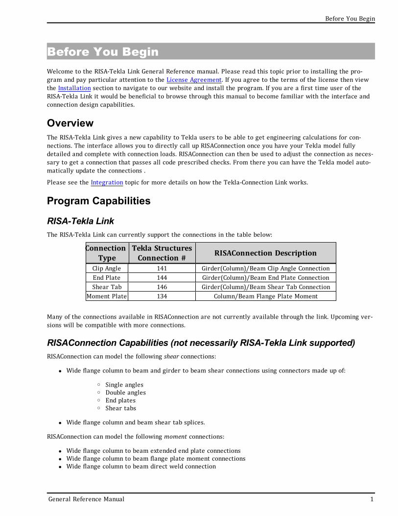
RISA-Tekla LinkThe RISA-Tekla Link can currently support the connections in the table below:
ConnectionType
Tekla StructuresConnection # RISAConnection Description
Clip Angle 141 Girder(Column)/Beam Clip Angle ConnectionEnd Plate 144 Girder(Column)/Beam End Plate ConnectionShear Tab 146 Girder(Column)/Beam Shear Tab Connection
Moment Plate 134 Column/Beam Flange Plate Moment
Many of the connections available in RISAConnection are not currently available through the link. Upcoming ver-sions will be compatible with more connections.
RISAConnection Capabilities (not necessarily RISA-Tekla Link supported)RISAConnection can model the following shear connections:
l Wide flange column to beam and girder to beam shear connections using connectors made up of:
o Single angleso Double angleso End plateso Shear tabs
l Wide flange column and beam shear tab splices.
RISAConnection can model the following moment connections:
l Wide flange column to beam extended end plate connectionsl Wide flange column to beam flange plate moment connectionsl Wide flange column to beam direct weld connection
General Reference Manual 1
l Wide flange column and beam end plate splicesl Wide flange column and beam flange plate splicesl Wide flange column and beam direct weld splices
RISAConnection can model the following brace connections:
l Single or double angle diagonal vertical brace connections with wide flange columns and beamsl Single or double angle chevron vertical brace connections with wide flange beams
Again, not all of these connections are currently supported with the RISA-Tekla link.
System Requirements
Operating SystemOne of the following operating systems is required:
l Microsoft Windows 8 (32 bit or 64 bit)l Microsoft Windows 7 SP1 (32 bit or 64 bit)l Microsoft Windows Vista SP2 (32 bit or 64 bit)l Microsoft Windows XP SP3 (32 bit only)
SoftwareThe following programs and versions required:
l Tekla Structures V18, V18.1, V19 and higherl RISAConnection V3.0.1, RISAConnection V3.0.1 Demo and higher
Demonstration Version: The RISA-Tekla Link will let you go from Tekla Structures to RISAConnection Demo. Todo this make sure that the RISAConnection Demo is open before pressing from Tekla Structures. The lim-itation is that the RISA-Tekla link will not let you transfer back to Tekla Structures to update the Tekla Struc-tures model, or give any results information in Tekla Structures. This does, however, allow you to work with anengineer who owns RISAConnection. For more information on this behavior see the RISA-Tekla Link IntegrationProcedure topic.
HardwareThe following hardware is required:
l 1 GHz or faster processorl 1024x768 or higher monitor resolutionl 2 (or more) button mouse, mouse wheel recommendedl 1 GB of RAMl 4 GB of hard disk space
License AgreementEND-USER LICENSE AGREEMENT FOR RISA TECHNOLOGIES, LLC® SOFTWARE
The RISA-Tekla Link software product (SOFTWARE PRODUCT) includes computer software, the associated media,any printed materials, and any electronic documentation. By installing, copying or otherwise using theSOFTWARE PRODUCT, you agree to be bound by the terms of this agreement. If you do not agree with the termsof this agreement RISA Technologies, LLC is unwilling to license the SOFTWARE PRODUCT to you. In such eventyou must delete any installations and destroy any copies of the SOFTWARE PRODUCT.
2 RISA-Tekla Link V2.0
Before You Begin
Before You Begin
Copyright 2013 by RISA Technologies, LLC. All rights reserved. The SOFTWARE PRODUCT is protected by UnitedStates copyright laws and various international treaties. All rights not specifically granted under this agreementare reserved by RISA TECHNOLOGIES, LLC.
1. SOFTWARE LICENSE. The SOFTWARE PRODUCT is licensed, not sold. All right, title and interest is andremains vested in RISA TECHNOLOGIES, LLC. You may not rent, lease, or lend the SOFTWARE PRODUCT. You arespecifically granted a license to the use of this program on no more than one CPU at any given time. The Net-work Version of the SOFTWARE PRODUCT is licensed for simultaneous use on a certain maximum number of net-work stations that varies on a per license basis. As part of the license to use the SOFTWARE PRODUCT, theprogram user acknowledges the reading, understanding and acceptance of all terms of this agreement. TheSOFTWARE PRODUCT may not be reviewed, compared or evaluated in any manner in any publication withoutexpressed written consent of RISA Technologies, LLC. You may not disassemble, decompile, reverse engineer ormodify in any way the SOFTWARE PRODUCT. If the SOFTWARE PRODUCT was purchased at a discounted pricefor educational purposes it may in no event be used for professional design purposes. The terms of this licenseagreement are binding in perpetuity.
2. DISCLAIMER. We intend that the information contained in the SOFTWARE PRODUCT be accurate and reliable,but it is entirely the responsibility of the program user to verify the accuracy and applicability of any resultsobtained from the SOFTWARE PRODUCT. The SOFTWARE PRODUCT is intended for use by professional engineersand architects who possess an understanding of structural mechanics. In no event will RISA Technologies, LLC orits officers be liable to anyone for any damages, including any lost profits, lost savings or lost data. In no eventwill RISA Technologies, LLC or its officers be liable for incidental, special, punitive or consequential damages orprofessional malpractice arising out of or in connection with the usage of the SOFTWARE PRODUCT, even if RISATechnologies, LLC or its officers have been advised of or should be aware of the possibility of suchdamages. RISA TECHNOLOGIES' entire liability shall be limited to the purchase price of the SOFTWAREPRODUCT.
3. LIMITED WARRANTY. RISA Technologies, LLC warrants that the SOFTWARE PRODUCT will operate but doesnot warrant that the SOFTWARE PRODUCT will operate error free or without interruption. RISA Technologiessole obligation and your exclusive remedy under this warranty will be to receive software support from RISATechnologies, LLC via telephone, email or fax. RISA Technologies, LLC shall only be obligated to provide supportfor the most recent version of the SOFTWARE PRODUCT. If your version of the SOFTWARE PRODUCT is not themost recent version RISA Technologies, LLC shall have no obligation to provide support in any form. Except asstated above the SOFTWARE PRODUCT is provided without warranty, express or implied, including without lim-itation the implied warranties of merchantability and fitness for a particular purpose.
4. PROTECTION DEVICE. In the event the SOFTWARE PRODUCT requires the use of a PROTECTION DEVICE tooperate, you are specifically prohibited from attempting to bypass the functionality of the PROTECTION DEVICEby any means. A lost or stolen PROTECTION DEVICE will not be replaced by RISA Technologies, LLC.
5. TERMINATION. RISA Technologies, LLC may terminate your right to use the SOFTWARE PRODUCT if you failto comply with the terms and conditions of this agreement. In such event you must delete any installations anddestroy any copies of the SOFTWARE PRODUCT and promptly return the SOFTWARE PRODUCT to RISA Tech-nologies.
6. CHOICE OF LAW. By entering into this Agreement in accordance with Paragraph 1, above, you have agreedto the exclusive jurisdiction of the State and Federal courts of the State of California, USA for resolution of anydispute you have relating to the SOFTWARE PRODUCT or related goods and services provided by RISA Tech-nologies, LLC. All disputes therefore shall be resolved in accordance with the laws of the State of California, USAand all parties to this Agreement expressly agree to exclusive jurisdiction within the State of California, USA. Nochoice of law rules of any jurisdiction apply.
"RISA" as applied to structural engineering software is a trademark of RISA Technologies, LLC.
General Reference Manual 3
Technical SupportComplete program support is available to registered owners of RISAConnection. This support is provided for thelife of the program. The "life of the program" is defined as the time period for which that version of the programis the current version. In other words. whenever a new version of RISAConnection is released, the life of the pre-vious version is considered to be ended.Technical support is a limited resource; first priority will always begiven to those clients who are current on their maintenance.
See Technical Support for a list of your support options.
InstallationPlease visit our website at: http://www.risa.com/forms/tekla_request.html
4 RISA-Tekla Link V2.0
Before You Begin
Application Interface
Application InterfaceHere we will give you a quick outline of the interface. See the RISA-Tekla Link Integration Procedure andRISAConnection Behavior topics for more information.
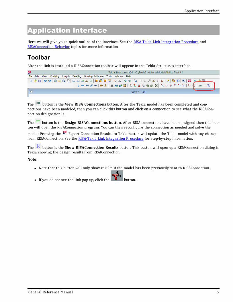
ToolbarAfter the link is installed a RISAConnection toolbar will appear in the Tekla Structures interface.
The button is the View RISA Connections button. After the Tekla model has been completed and con-nections have been modeled, then you can click this button and click on a connection to see what the RISACon-nection designation is.
The button is the Design RISAConnections button. After RISA connections have been assigned then this but-ton will open the RISAConnection program. You can then reconfigure the connection as needed and solve the
model. Pressing the Export Connection Results to Tekla button will update the Tekla model with any changesfrom RISAConnection. See the RISA-Tekla Link Integration Procedure for step-by-step information.
The button is the Show RISAConnection Results button. This button will open up a RISAConnection dialog inTekla showing the design results from RISAConnection.
Note:
l Note that this button will only show results if the model has been previously sent to RISAConnection.
l If you do not see the link pop up, click the button.
General Reference Manual 5
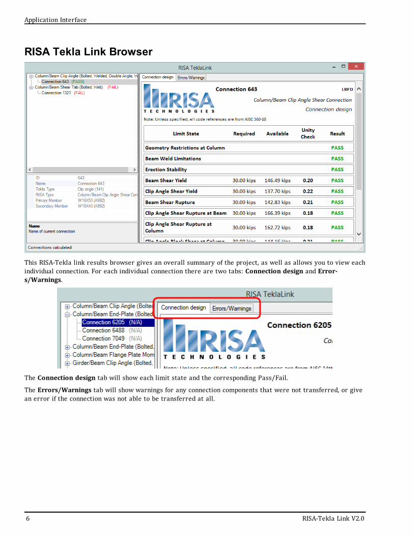
RISA Tekla Link Browser
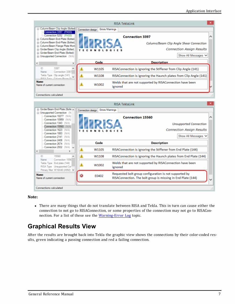
This RISA-Tekla link results browser gives an overall summary of the project, as well as allows you to view eachindividual connection. For each individual connection there are two tabs: Connection design and Error-s/Warnings.
The Connection design tab will show each limit state and the corresponding Pass/Fail.
The Errors/Warnings tab will show warnings for any connection components that were not transferred, or givean error if the connection was not able to be transferred at all.
6 RISA-Tekla Link V2.0
Application Interface
Application Interface
Note:
l There are many things that do not translate between RISA and Tekla. This in turn can cause either theconnection to not go to RISAConnection, or some properties of the connection may not go to RISACon-nection. For a list of these see the Warning-Error Log topic.
Graphical Results ViewAfter the results are brought back into Tekla the graphic view shows the connections by their color-coded res-ults, green indicating a passing connection and red a failing connection.
General Reference Manual 7
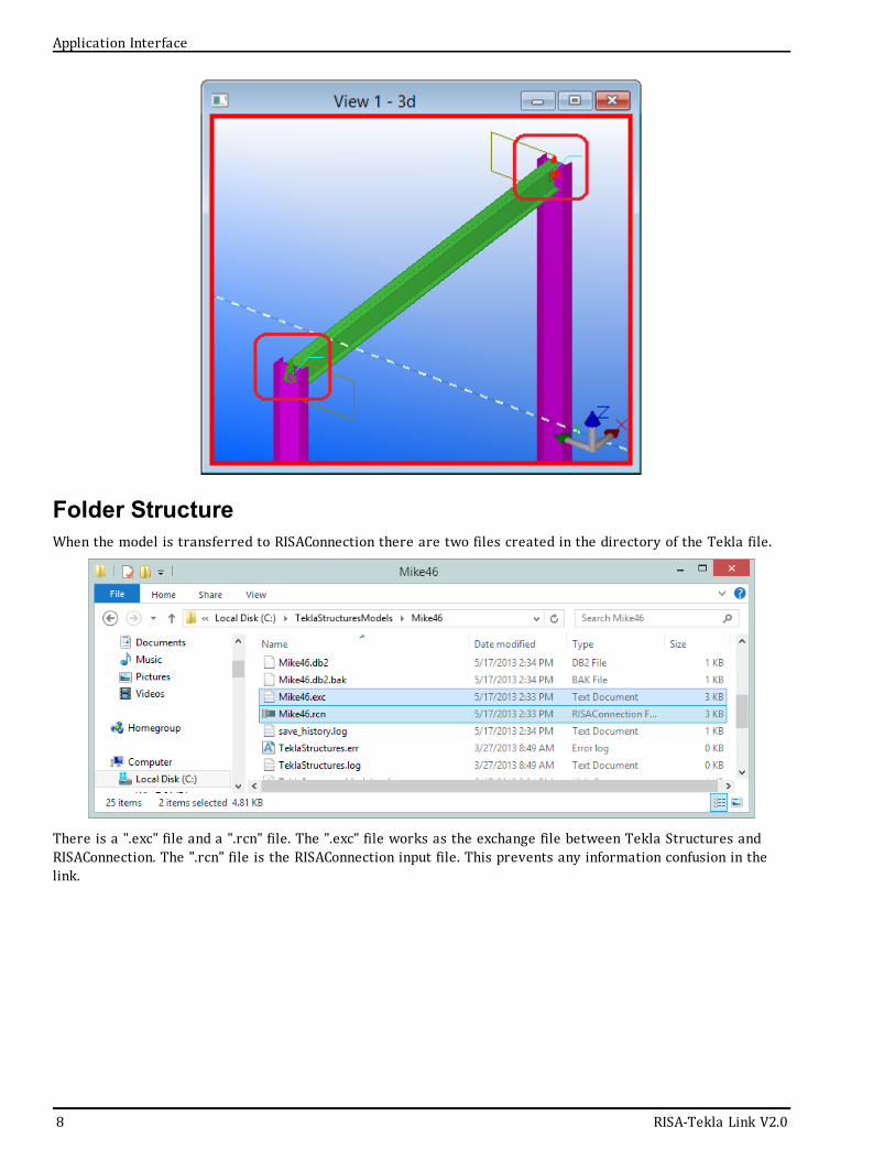
Folder StructureWhen the model is transferred to RISAConnection there are two files created in the directory of the Tekla file.
There is a ".exc" file and a ".rcn" file. The ".exc" file works as the exchange file between Tekla Structures andRISAConnection. The ".rcn" file is the RISAConnection input file. This prevents any information confusion in thelink.
8 RISA-Tekla Link V2.0
Application Interface
RISA-Tekla Link Integration Procedure
RISA-Tekla Link Integration ProcedureThe RISA-Tekla link sends the geometry, connection loads, shape types and connection types automatically fromTekla into RISAConnection. This allows you to design your connections in RISAConnection and then bring the res-ults back into Tekla to have your structure updated and to view the results.
Here we will walk through the steps required to design connections using this integration.
1. Completing the Tekla Structures ModelYou must first model your structure in Tekla, including the connections and the loading. RISA only supports spe-cific connections with the RISA-Tekla link. This list can be found in the Before You Begin topic. If a connection isnot one of these supported connections then it will show up as an Unsupported Connection in the RISA-Teklalink.
For information on loads see the RISAConnection Behavior topic.
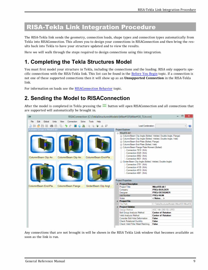
2. Sending the Model to RISAConnectionAfter the model is completed in Tekla pressing the button will open RISAConnection and all connections thatare supported will automatically be brought in.
Any connections that are not brought in will be shown in the RISA Tekla Link window that becomes available assoon as the link is run.
General Reference Manual 9
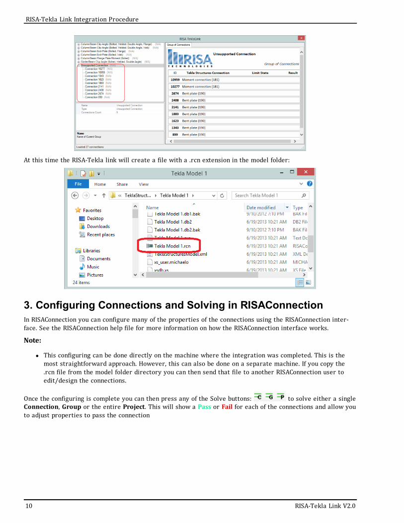
At this time the RISA-Tekla link will create a file with a .rcn extension in the model folder:
3. Configuring Connections and Solving in RISAConnectionIn RISAConnection you can configure many of the properties of the connections using the RISAConnection inter-face. See the RISAConnection help file for more information on how the RISAConnection interface works.
Note:
l This configuring can be done directly on the machine where the integration was completed. This is themost straightforward approach. However, this can also be done on a separate machine. If you copy the.rcn file from the model folder directory you can then send that file to another RISAConnection user toedit/design the connections.
Once the configuring is complete you can then press any of the Solve buttons: to solve either a singleConnection, Group or the entire Project. This will show a Pass or Fail for each of the connections and allow youto adjust properties to pass the connection
10 RISA-Tekla Link V2.0
RISA-Tekla Link Integration Procedure
RISA-Tekla Link Integration Procedure
.
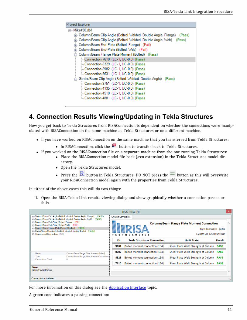
4. Connection Results Viewing/Updating in Tekla StructuresHow you get back to Tekla Structures from RISAConnection is dependent on whether the connections were manip-ulated with RISAConnection on the same machine as Tekla Structures or on a different machine.
l If you have worked on RISAConnection on the same machine that you transferred from Tekla Structures:
l In RISAConnection, click the button to transfer back to Tekla Structures.l If you worked on the RISAConnection file on a separate machine from the one running Tekla Structures:
l Place the RISAConnection model file back (.rcn extension) in the Tekla Structures model dir-ectory.
l Open the Tekla Structures model.
l Press the button in Tekla Structures. DO NOT press the button as this will overwriteyour RISAConnection model again with the properties from Tekla Structures.
In either of the above cases this will do two things:
1. Open the RISA-Tekla Link results viewing dialog and show graphically whether a connection passes orfails.
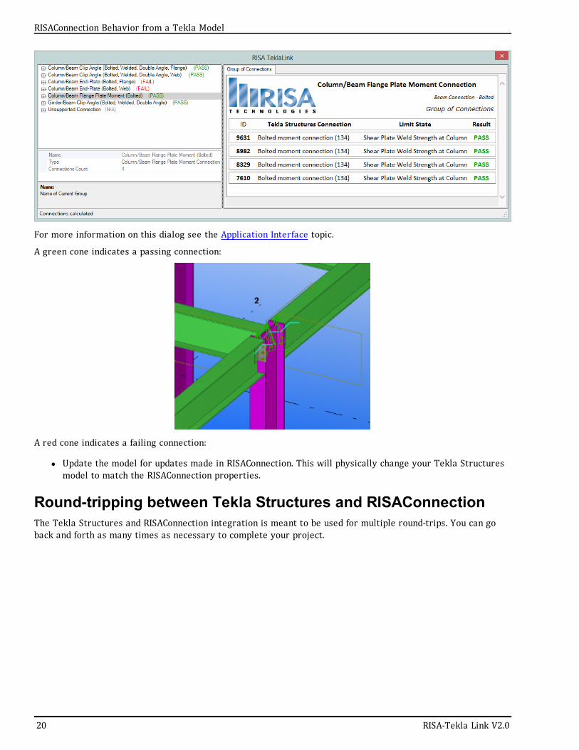
For more information on this dialog see the Application Interface topic.
A green cone indicates a passing connection:
General Reference Manual 11
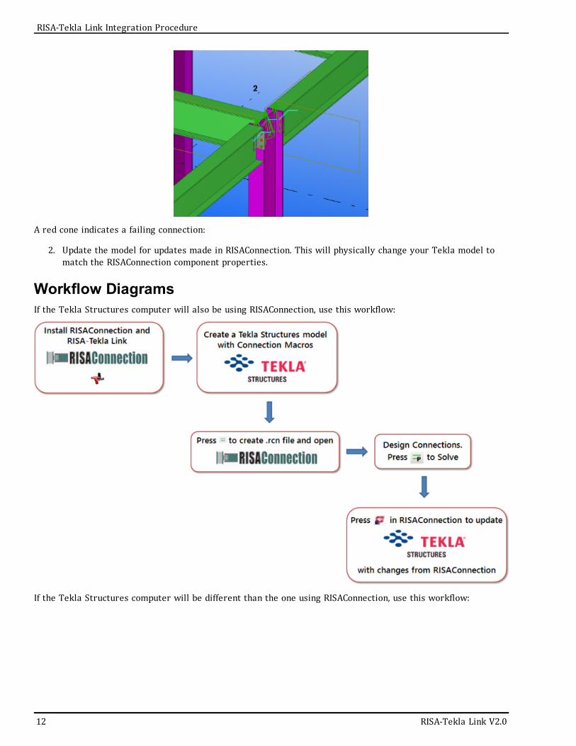
A red cone indicates a failing connection:
2. Update the model for updates made in RISAConnection. This will physically change your Tekla model tomatch the RISAConnection component properties.
Workflow DiagramsIf the Tekla Structures computer will also be using RISAConnection, use this workflow:
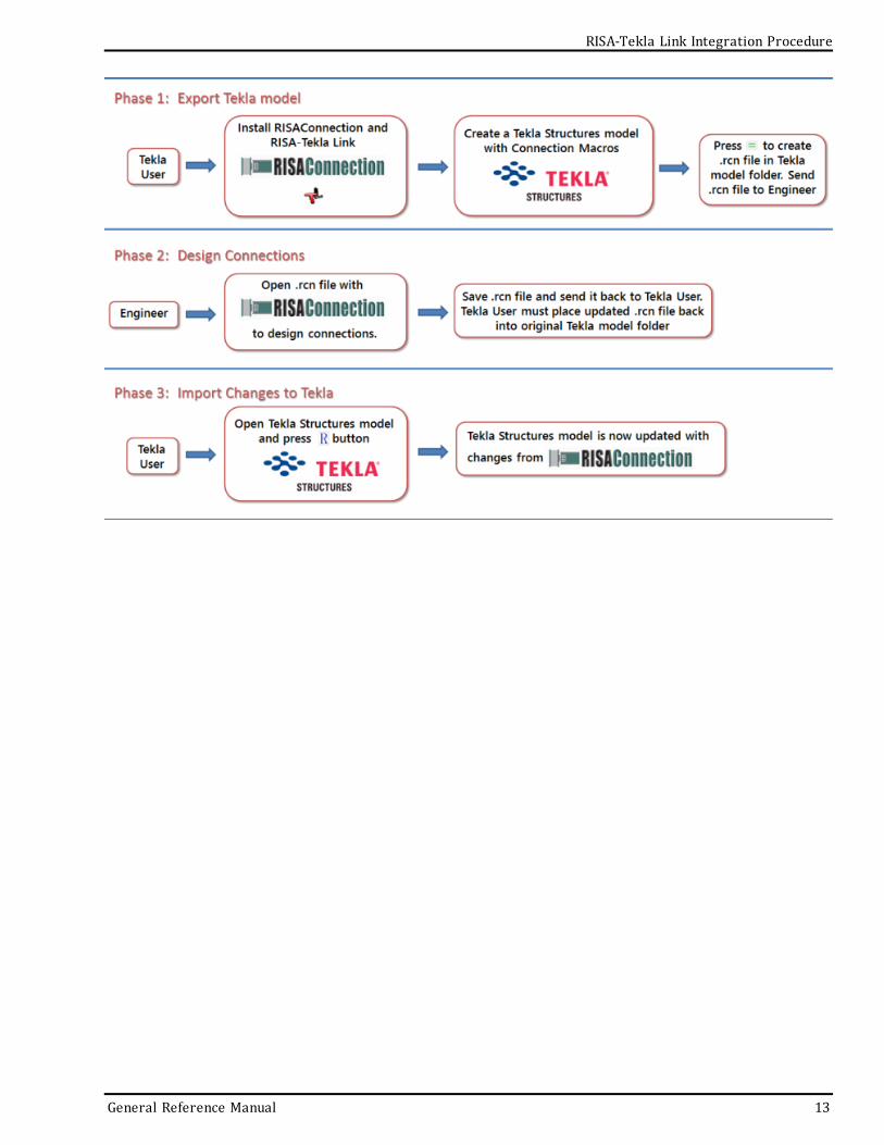
If the Tekla Structures computer will be different than the one using RISAConnection, use this workflow:
12 RISA-Tekla Link V2.0
RISA-Tekla Link Integration Procedure
RISA-Tekla Link Integration Procedure
General Reference Manual 13
RISAConnection Behavior from a Tekla ModelWhen transferring Tekla connections to RISAConnection the majority of the behavior is similar to standaloneRISAConnection. For this behavior view the RISAConnection General Reference which can be found on the Docu-mentation page of our website at http://www.risa.com/d_documentation.html
This topic details specific variations from the standard RISAConnection behavior. To learn the steps of taking theTekla model to RISAConnection, view the Tekla Connection Procedure topic.
When first coming into RISAConnection from Tekla you will see that the file is populated with all of theVALID connections. Thus, only connections that RISAConnection can actually design will be brought over. The actof invoking RISAConnection from Tekla (using the button) will create a RISAConnection file (with a .rcn exten-sion) and a RISA-Tekla Link exchange file (with a .exc extension) and will be located in the same directory.
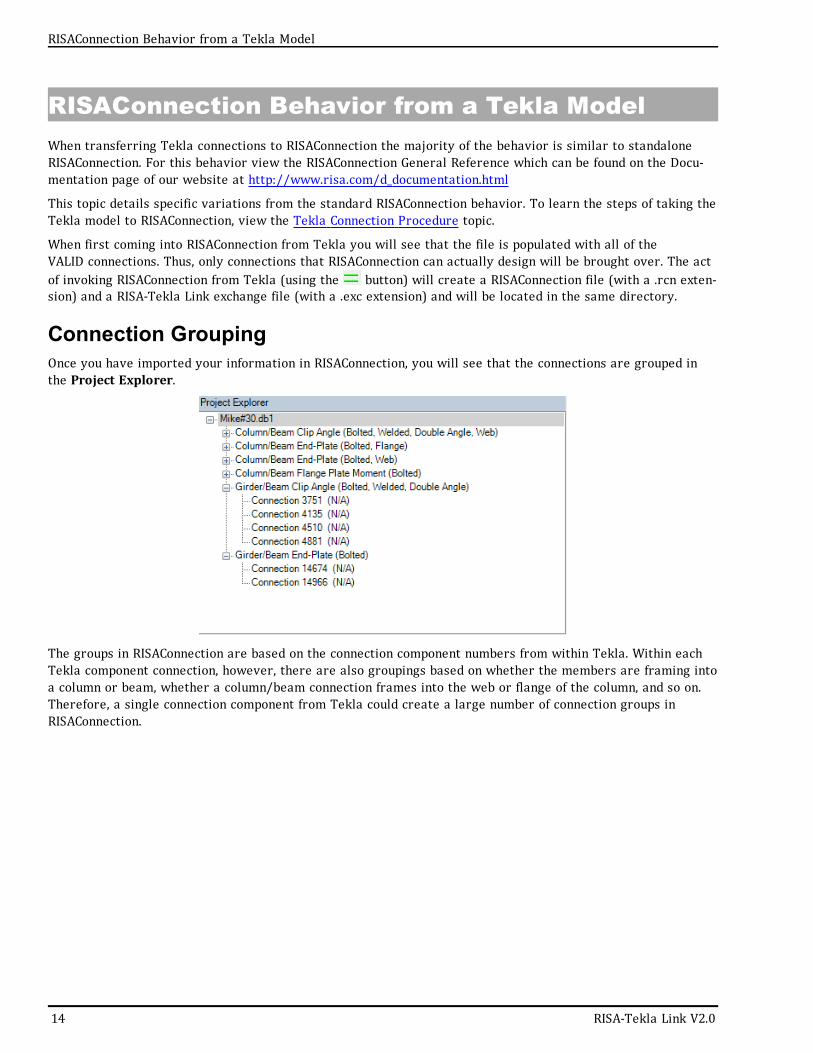
Connection GroupingOnce you have imported your information in RISAConnection, you will see that the connections are grouped inthe Project Explorer.
The groups in RISAConnection are based on the connection component numbers from within Tekla. Within eachTekla component connection, however, there are also groupings based on whether the members are framing intoa column or beam, whether a column/beam connection frames into the web or flange of the column, and so on.Therefore, a single connection component from Tekla could create a large number of connection groups inRISAConnection.
14 RISA-Tekla Link V2.0
RISAConnection Behavior from a Tekla Model

RISAConnection Behavior from a Tekla Model
Grouping BehaviorIn the Project Explorer there are three levels: Project level, Group level, and Connection level. These levels arenested within each other and allow you to change design and connection properties quickly and easily. There arealso properties that can only be changed within Tekla Structures. Here we will discuss these different connectionproperty categories and how to use them properly.
Tekla Structures LevelItems that can only be modified from Tekla Structures:
l Connection Typesl Connection Categories (bolted vs welded, single angle vs double angle, etc)l Loadingl Member Shapes
If you wish to modify any of these properties you need to go back to the Tekla Structures model, make thechange, and then re-export to RISAConnection.
Project LevelWhen you click the project label in the Project Explorer, the Project Properties are then shown.
General Reference Manual 15
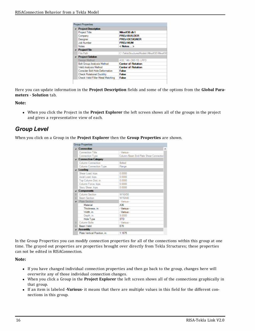
Here you can update information in the Project Description fields and some of the options from the Global Para-meters - Solution tab.
Note:
l When you click the Project in the Project Explorer the left screen shows all of the groups in the projectand gives a representative view of each.
Group LevelWhen you click on a Group in the Project Explorer then the Group Properties are shown.
In the Group Properties you can modify connection properties for all of the connections within this group at onetime. The grayed out properties are properties brought over directly from Tekla Structures; these propertiescan not be edited in RISAConnection.
Note:
l If you have changed individual connection properties and then go back to the group, changes here willoverwrite any of those individual connection changes.
l When you click a Group in the Project Explorer the left screen shows all of the connections graphically inthat group.
l If an item is labeled -Various- it means that there are multiple values in this field for the different con-nections in this group.
16 RISA-Tekla Link V2.0
RISAConnection Behavior from a Tekla Model
RISAConnection Behavior from a Tekla Model
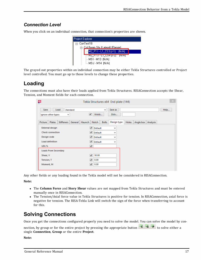
Connection LevelWhen you click on an individual connection, that connection's properties are shown.
The grayed out properties within an individual connection may be either Tekla Structures controlled or Projectlevel controlled. You must go up to those levels to change these properties.
LoadingThe connections must also have their loads applied from Tekla Structures. RISAConnection accepts the Shear,Tension, and Moment fields for each connection.
Any other fields or any loading found in the Tekla model will not be considered in RISAConnection.
Note:
l The Column Force and Story Shear values are not mapped from Tekla Structures and must be enteredmanually once in RISAConnection.
l The Tension/Axial force value in Tekla Structures is positive for tension. In RISAConnection, axial force isnegative for tension. The RISA-Tekla Link will switch the sign of the force when transferring to accountfor this.
Solving ConnectionsOnce you get the connections configured properly you need to solve the model. You can solve the model by con-
nection, by group or for the entire project by pressing the appropriate button to solve either asingle Connection, Group or the entire Project.
Note:
General Reference Manual 17
l If you are using RISAConnection as a standalone program then these solve buttons have no use becausethe model is re-solved automatically each time a change is made.
Viewing Results (in RISAConnection)Once you have a connection, a group, or the entire project solved you will be able to view results via the ProjectExplorer or Reports tab.
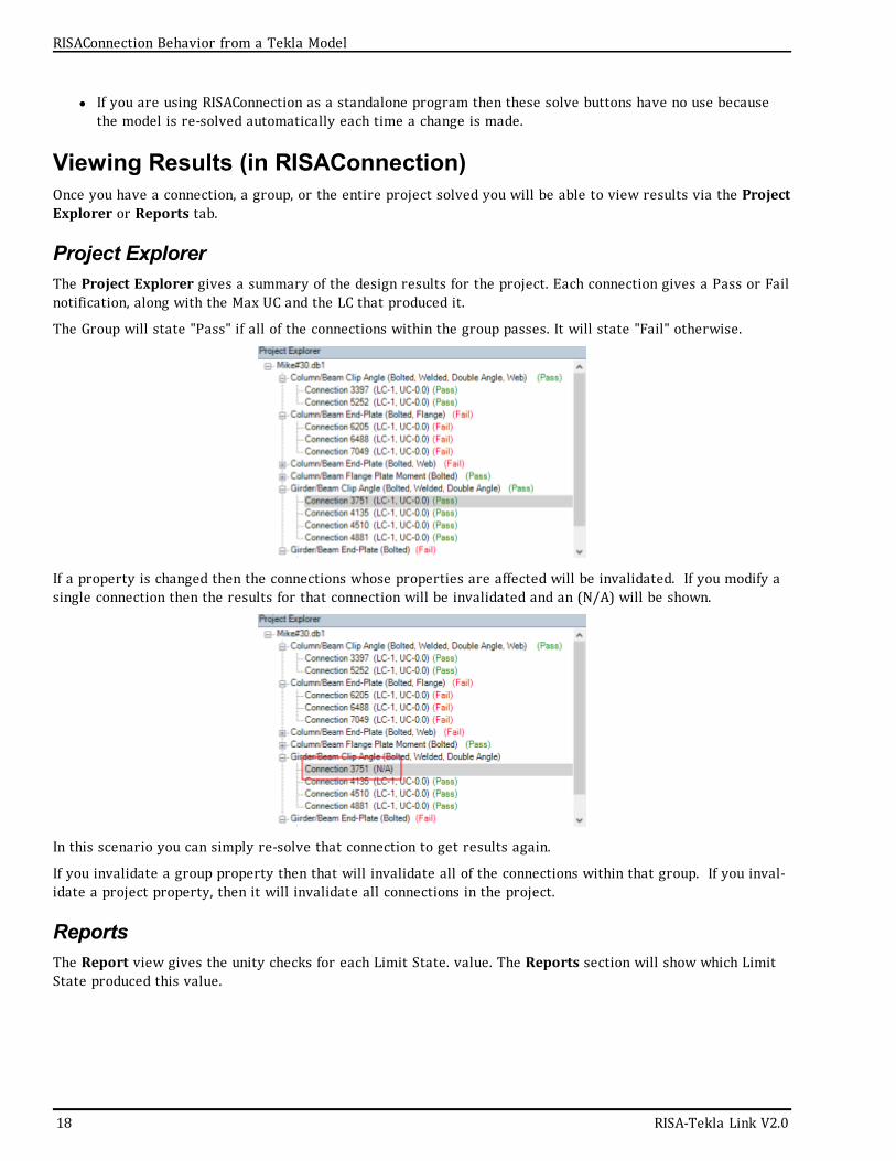
Project ExplorerThe Project Explorer gives a summary of the design results for the project. Each connection gives a Pass or Failnotification, along with the Max UC and the LC that produced it.
The Group will state "Pass" if all of the connections within the group passes. It will state "Fail" otherwise.
If a property is changed then the connections whose properties are affected will be invalidated. If you modify asingle connection then the results for that connection will be invalidated and an (N/A) will be shown.
In this scenario you can simply re-solve that connection to get results again.
If you invalidate a group property then that will invalidate all of the connections within that group. If you inval-idate a project property, then it will invalidate all connections in the project.
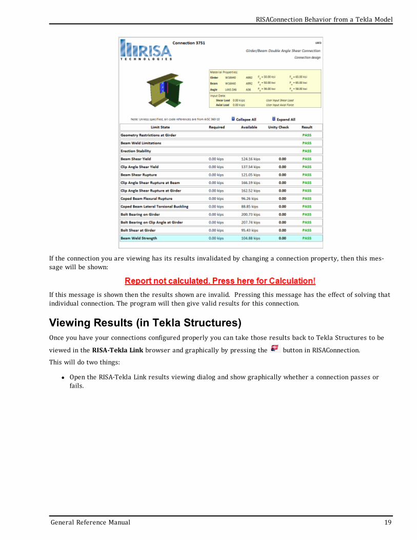
ReportsThe Report view gives the unity checks for each Limit State. value. The Reports section will show which LimitState produced this value.
18 RISA-Tekla Link V2.0
RISAConnection Behavior from a Tekla Model
RISAConnection Behavior from a Tekla Model
If the connection you are viewing has its results invalidated by changing a connection property, then this mes-sage will be shown:
If this message is shown then the results shown are invalid. Pressing this message has the effect of solving thatindividual connection. The program will then give valid results for this connection.
Viewing Results (in Tekla Structures)Once you have your connections configured properly you can take those results back to Tekla Structures to be
viewed in the RISA-Tekla Link browser and graphically by pressing the button in RISAConnection.
This will do two things:
l Open the RISA-Tekla Link results viewing dialog and show graphically whether a connection passes orfails.
General Reference Manual 19
For more information on this dialog see the Application Interface topic.
A green cone indicates a passing connection:
A red cone indicates a failing connection:
l Update the model for updates made in RISAConnection. This will physically change your Tekla Structuresmodel to match the RISAConnection properties.
Round-tripping between Tekla Structures and RISAConnectionThe Tekla Structures and RISAConnection integration is meant to be used for multiple round-trips. You can goback and forth as many times as necessary to complete your project.
20 RISA-Tekla Link V2.0
RISAConnection Behavior from a Tekla Model
Mapping Behavior
Mapping BehaviorWhen transferring Tekla Structures connections to RISAConnection the properties are mapped over from TeklaStructures to RISAConnection and vice-versa.. Tekla Structures and RISAConnection are very different and werebuilt for different applications. However, many properties can be mapped directly between the two programs.
Properties are characterized as one of three different classifications: read-only properties, editable propertiesand ignored properties. Here we will explore each classification.
Read-Only PropertiesRead-only properties are properties brought in from Tekla Structures that can not be updated in RISAConnection.These are properties inherent to the structure itself. These include section properties, material properties andloading. These are items that in most cases the connection designer does not have control of. Thus, these mustbe considered in the Tekla Structures model and only this information comes into RISAConnection. There arealso some other properties that for mapping purposes are brought over as read-only as well.
Bolt Hole ConfigurationIn RISAConnection you can have multiple configurations that Tekla Structures does not support. Because of this itis required to set the bolt hole types in Tekla Structures only.
For more information see the Bolt Hole Mapping section ahead.
Editable PropertiesEditable properties are properties brought in from Tekla Structures that can be updated in RISAConnection.These are properties specific to connection design that the connection designer would have control over. Thisincludes welds, bolt criteria, plate and clip angle criteria, offsets, etc. These properties, if updated in RISACon-nection, will be updated in the Tekla Structures model when the results are exported back from RISAConnection.
Ignored PropertiesIgnored properties are properties completely ignored by the RISA-Tekla Link. These are generally elements inTekla Structures that are not supported in RISAConnection. Some examples of properties ignored by the link:
l Haunch plate informationl Fill information for Connection 134l Folded plates and fitting plates for Connection 144l Seat angles and seat platesl Column stiffeners on shear connections
How Mapping WorksTekla Structures and RISAConnection have different nomenclatures for how elements are named. To map thesenames between the two programs a mapping file is generated in the RISA-Tekla Link install location:
General Reference Manual 21
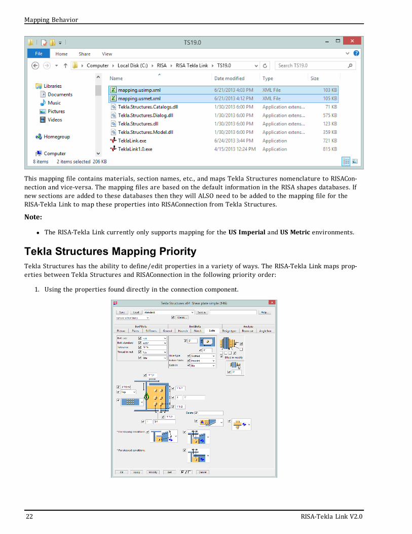
This mapping file contains materials, section names, etc., and maps Tekla Structures nomenclature to RISACon-nection and vice-versa. The mapping files are based on the default information in the RISA shapes databases. Ifnew sections are added to these databases then they will ALSO need to be added to the mapping file for theRISA-Tekla Link to map these properties into RISAConnection from Tekla Structures.
Note:
l The RISA-Tekla Link currently only supports mapping for the US Imperial and US Metric environments.
Tekla Structures Mapping PriorityTekla Structures has the ability to define/edit properties in a variety of ways. The RISA-Tekla Link maps prop-erties between Tekla Structures and RISAConnection in the following priority order:
1. Using the properties found directly in the connection component.
22 RISA-Tekla Link V2.0
Mapping Behavior
Mapping Behavior
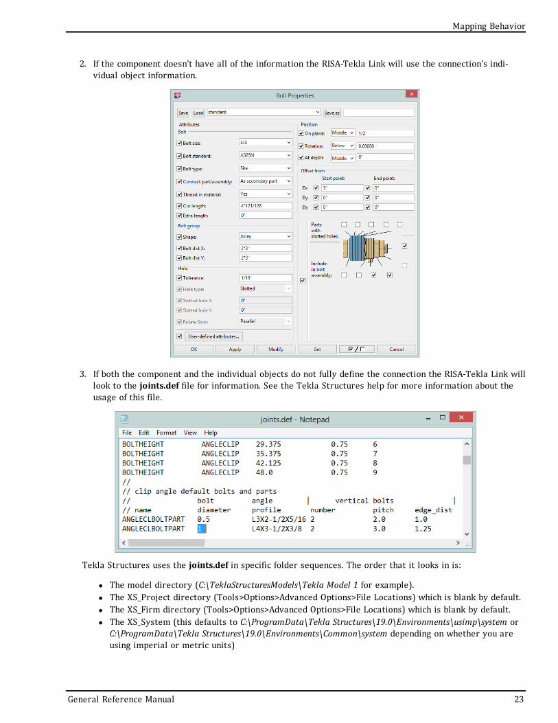
2. If the component doesn't have all of the information the RISA-Tekla Link will use the connection's indi-vidual object information.
3. If both the component and the individual objects do not fully define the connection the RISA-Tekla Link willlook to the joints.def file for information. See the Tekla Structures help for more information about theusage of this file.
Tekla Structures uses the joints.def in specific folder sequences. The order that it looks in is:
l The model directory (C:\TeklaStructuresModels\Tekla Model 1 for example).l The XS_Project directory (Tools>Options>Advanced Options>File Locations) which is blank by default.l The XS_Firm directory (Tools>Options>Advanced Options>File Locations) which is blank by default.l The XS_System (this defaults to C:\ProgramData\Tekla Structures\19.0\Environments\usimp\system or
C:\ProgramData\Tekla Structures\19.0\Environments\Common\system depending on whether you areusing imperial or metric units)
General Reference Manual 23
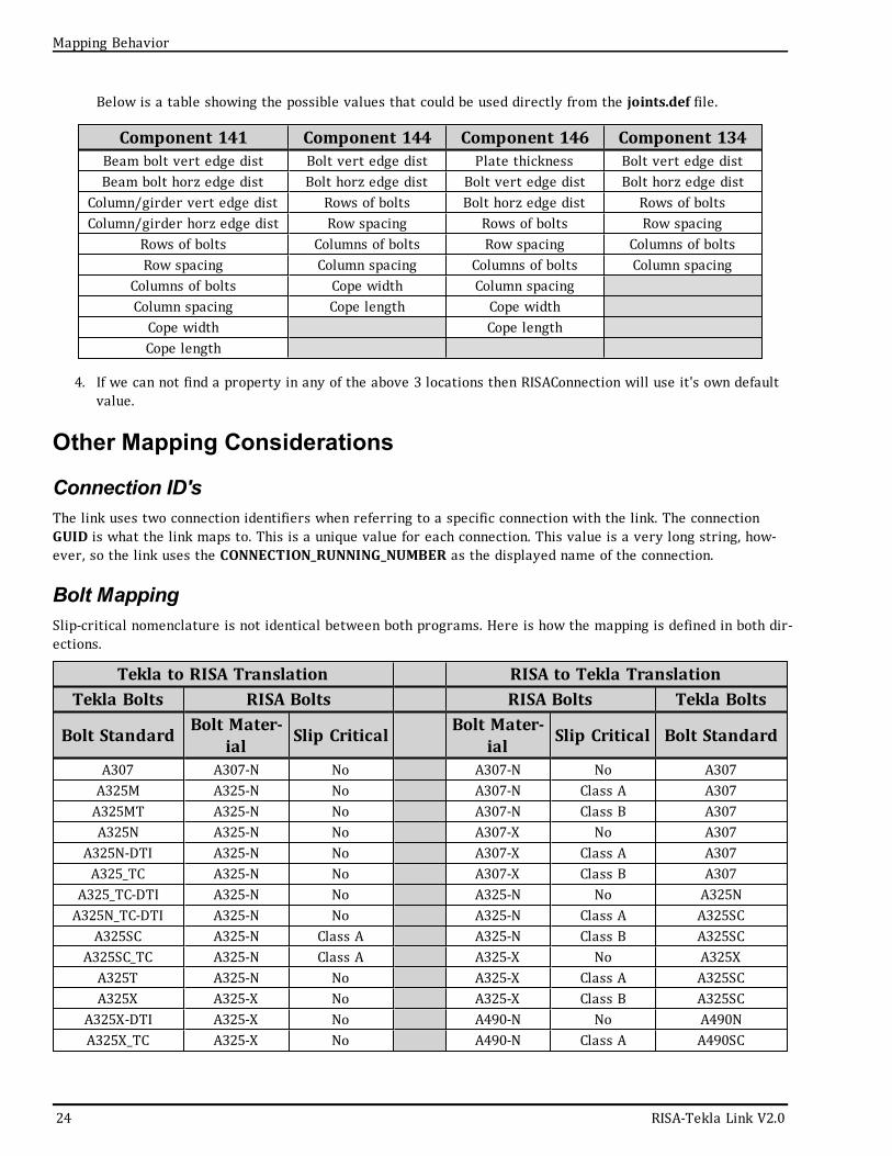
Below is a table showing the possible values that could be used directly from the joints.def file.
Component 141 Component 144 Component 146 Component 134Beam bolt vert edge dist Bolt vert edge dist Plate thickness Bolt vert edge distBeam bolt horz edge dist Bolt horz edge dist Bolt vert edge dist Bolt horz edge dist
Column/girder vert edge dist Rows of bolts Bolt horz edge dist Rows of boltsColumn/girder horz edge dist Row spacing Rows of bolts Row spacing
Rows of bolts Columns of bolts Row spacing Columns of boltsRow spacing Column spacing Columns of bolts Column spacing
Columns of bolts Cope width Column spacingColumn spacing Cope length Cope widthCope width Cope lengthCope length
4. If we can not find a property in any of the above 3 locations then RISAConnection will use it's own defaultvalue.
Other Mapping Considerations
Connection ID'sThe link uses two connection identifiers when referring to a specific connection with the link. The connectionGUID is what the link maps to. This is a unique value for each connection. This value is a very long string, how-ever, so the link uses the CONNECTION_RUNNING_NUMBER as the displayed name of the connection.
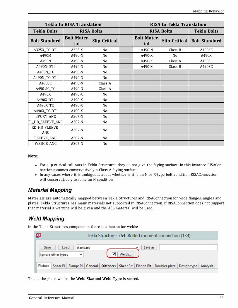
Bolt MappingSlip-critical nomenclature is not identical between both programs. Here is how the mapping is defined in both dir-ections.
Tekla to RISA Translation RISA to Tekla TranslationTekla Bolts RISA Bolts RISA Bolts Tekla Bolts
Bolt Standard Bolt Mater-ial Slip Critical Bolt Mater-
ial Slip Critical Bolt Standard
A307 A307-N No A307-N No A307A325M A325-N No A307-N Class A A307A325MT A325-N No A307-N Class B A307A325N A325-N No A307-X No A307
A325N-DTI A325-N No A307-X Class A A307A325_TC A325-N No A307-X Class B A307
A325_TC-DTI A325-N No A325-N No A325NA325N_TC-DTI A325-N No A325-N Class A A325SC
A325SC A325-N Class A A325-N Class B A325SCA325SC_TC A325-N Class A A325-X No A325XA325T A325-N No A325-X Class A A325SCA325X A325-X No A325-X Class B A325SC
A325X-DTI A325-X No A490-N No A490NA325X_TC A325-X No A490-N Class A A490SC
24 RISA-Tekla Link V2.0
Mapping Behavior
Mapping Behavior
Tekla to RISA Translation RISA to Tekla TranslationTekla Bolts RISA Bolts RISA Bolts Tekla Bolts
Bolt Standard Bolt Mater-ial Slip Critical Bolt Mater-
ial Slip Critical Bolt Standard
A325X_TC-DTI A325-X No A490-N Class B A490SCA490M A490-N No A490-X No A490XA490N A490-N No A490-X Class A A490SC
A490N-DTI A490-N No A490-X Class B A490SCA490N_TC A490-N No
A490N_TC-DTI A490-N NoA490SC A490-N Class A
A490 SC_TC A490-N Class AA490X A490-X No
A490X-DTI A490-X NoA490X_TC A490-X No
A490X_TC-DTI A490-X NoEPOXY_ANC A307-N No
FL_HD_SLEEVE_ANC A307-N NoRD_HD_SLEEVE_
ANC A307-N No
SLEEVE_ANC A307-N NoWEDGE_ANC A307-N No
Note:
l For slip-critical call-outs in Tekla Structures they do not give the faying surface. In this instance RISACon-nection assumes conservatively a Class A faying surface.
l In any cases where it is ambiguous about whether is it is an N or X-type bolt condition RISAConnectionwill conservatively assume an N condition.
Material MappingMaterials are automatically mapped between Tekla Structures and RISAConnection for wide flanges, angles andplates. Tekla Structures has many materials not supported in RISAConnection. If RISAConnection does not supportthat material a warning will be given and the A36 material will be used.
Weld MappingIn the Tekla Structures components there is a button for welds:
This is the place where the Weld Size andWeld Type is stored.
General Reference Manual 25

A couple of notes on this dialog:
l By default a large amount of welds are defined. Most likely all of these welds will not be used and a warn-ing message will be created in the RISA-Tekla Link.
l For doubler plates in connection 134 it is weld 2 which controls the weld parameters for the weld fromthe doubler plate to the column. In Tekla Structures there is a single input for the doubler plate weld allthe way around. In RISAConnection there is a left/right input and a top/bottom input where these weldscan be not. Because of this, any edits to the weld type or weld size must be done in Tekla Structures.
In Tekla Structures the Electrode Classification is almost never stored in the component. You must click on theindividual weld object to view this information. The table shows how this information is mapped.
Tekla Electrode Classification RISA Electrode Type35 Unsupported (use E70)42 Unsupported (use E70)50 Unsupported (use E70)
E60XX E60E70XX E70E80XX E80E90XX E90E70XX* E100E70XX* E110
Note:
l It is possible in RISAConnection to use E100 or E110 electrode types. However, Tekla Structures does notsupport these and the link will default to E70XX.
l Because the Electrode Classification is not stored in the component (only in the individual weld object),any modifications to the component will overwrite this information from the individual weld object withblank information. This will cause RISAConnection to bring in the default again the next time the model islinked.
Bolt Hole MappingIn RISAConnection you can have multiple configurations that Tekla Structures does not support. Because of this itis required to set the bolt hole types in Tekla Structures only.
In Tekla it is possible to map the type of bolt holes to RISAConnection.
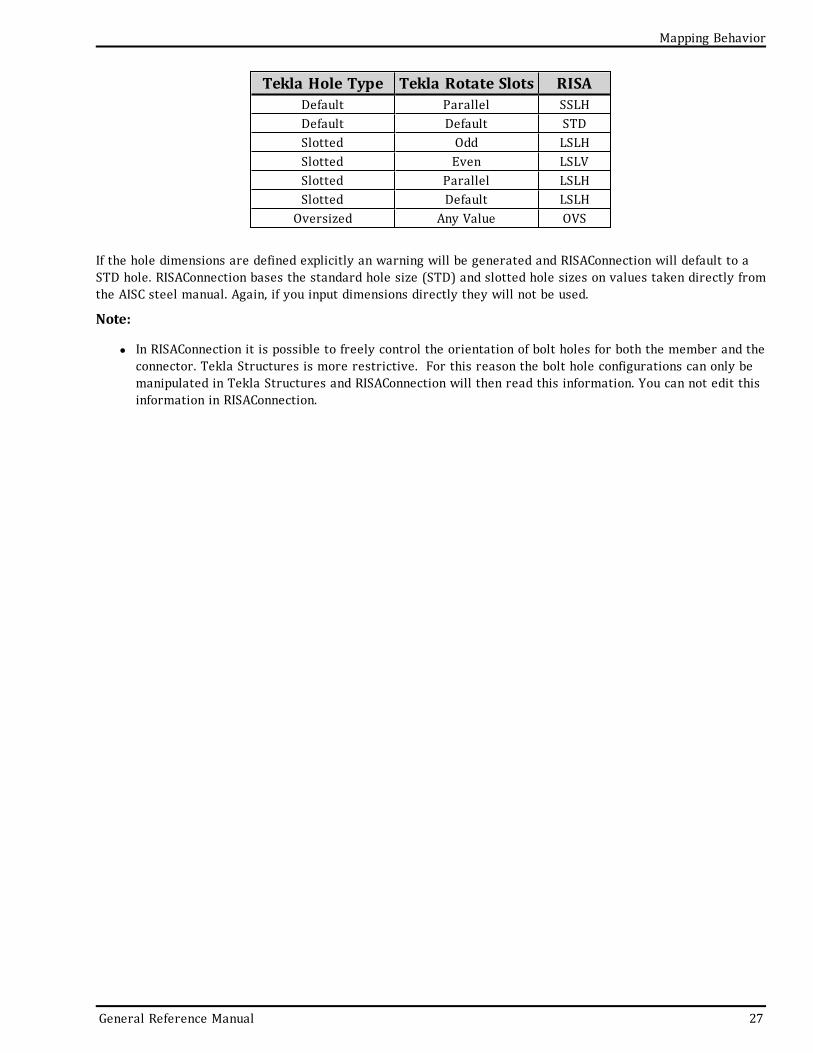
This is the nomenclature that is used:
Tekla Hole Type Tekla Rotate Slots RISADefault Odd SSLHDefault Even SSLV
26 RISA-Tekla Link V2.0
Mapping Behavior
Mapping Behavior
Tekla Hole Type Tekla Rotate Slots RISADefault Parallel SSLHDefault Default STDSlotted Odd LSLHSlotted Even LSLVSlotted Parallel LSLHSlotted Default LSLHOversized Any Value OVS
If the hole dimensions are defined explicitly an warning will be generated and RISAConnection will default to aSTD hole. RISAConnection bases the standard hole size (STD) and slotted hole sizes on values taken directly fromthe AISC steel manual. Again, if you input dimensions directly they will not be used.
Note:
l In RISAConnection it is possible to freely control the orientation of bolt holes for both the member and theconnector. Tekla Structures is more restrictive. For this reason the bolt hole configurations can only bemanipulated in Tekla Structures and RISAConnection will then read this information. You can not edit thisinformation in RISAConnection.
General Reference Manual 27
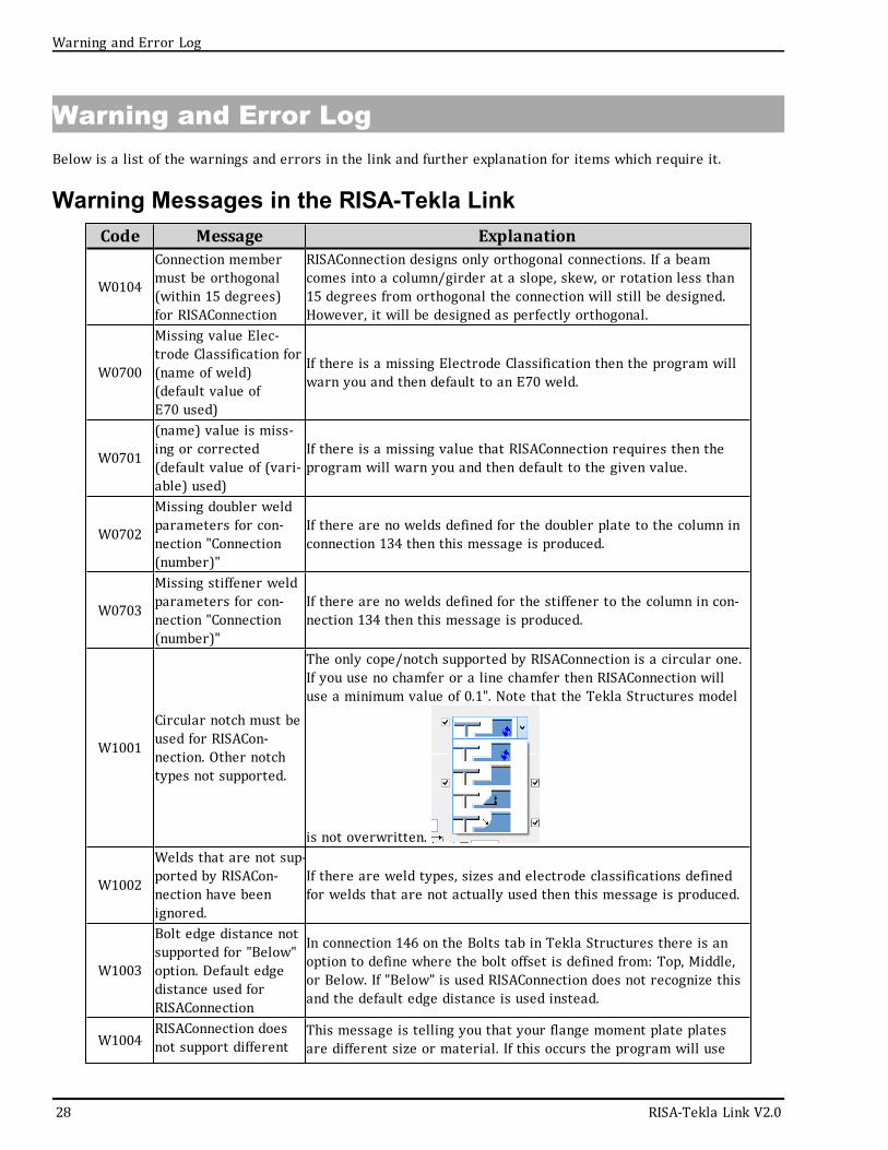
Warning and Error LogBelow is a list of the warnings and errors in the link and further explanation for items which require it.
Warning Messages in the RISA-Tekla LinkCode Message Explanation
W0104
Connection membermust be orthogonal(within 15 degrees)for RISAConnection
RISAConnection designs only orthogonal connections. If a beamcomes into a column/girder at a slope, skew, or rotation less than15 degrees from orthogonal the connection will still be designed.However, it will be designed as perfectly orthogonal.
W0700
Missing value Elec-trode Classification for(name of weld)(default value ofE70 used)
If there is a missing Electrode Classification then the program willwarn you and then default to an E70 weld.
W0701
(name) value is miss-ing or corrected(default value of (vari-able) used)
If there is a missing value that RISAConnection requires then theprogram will warn you and then default to the given value.
W0702
Missing doubler weldparameters for con-nection "Connection(number)"
If there are no welds defined for the doubler plate to the column inconnection 134 then this message is produced.
W0703
Missing stiffener weldparameters for con-nection "Connection(number)"
If there are no welds defined for the stiffener to the column in con-nection 134 then this message is produced.
W1001
Circular notch must beused for RISACon-nection. Other notchtypes not supported.
The only cope/notch supported by RISAConnection is a circular one.If you use no chamfer or a line chamfer then RISAConnection willuse a minimum value of 0.1". Note that the Tekla Structures model
is not overwritten.
W1002
Welds that are not sup-ported by RISACon-nection have beenignored.
If there are weld types, sizes and electrode classifications definedfor welds that are not actually used then this message is produced.
W1003
Bolt edge distance notsupported for "Below"option. Default edgedistance used forRISAConnection
In connection 146 on the Bolts tab in Tekla Structures there is anoption to define where the bolt offset is defined from: Top, Middle,or Below. If "Below" is used RISAConnection does not recognize thisand the default edge distance is used instead.
W1004RISAConnection doesnot support different
This message is telling you that your flange moment plate platesare different size or material. If this occurs the program will use
28 RISA-Tekla Link V2.0
Warning and Error Log
Warning and Error Log
Code Message Explanationsizes or materials formoment plates. Bothmoment plates mustbe the same for "Con-nection (number)"
the top plate parameters, updating the Tekla Structures model aswell.
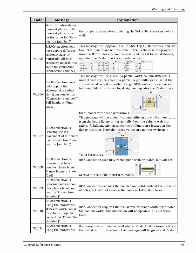
W1005
RISAConnection doesnot support differentstiffener sizes ormaterials. All fourstiffeners must be thesame for connection"Connection (number)"
This message will appear if the Top NS, Top FS, Bottom NS, and Bot-tom FS stiffeners are not the same. If this is the case the programuses the Bottom NS size and material and uses it for all stiffeners,updating the Tekla Structures model as well.
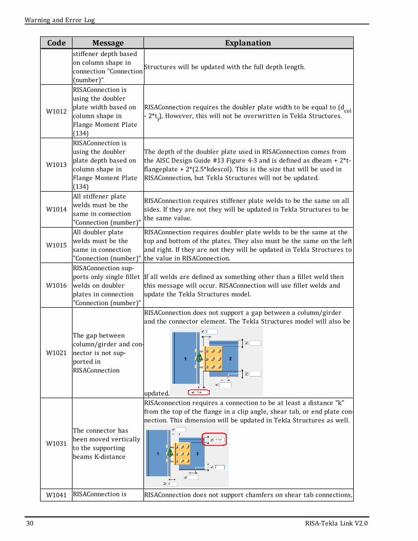
W1006
RISAConnection doesnot support thestiffener size reduc-tion from connection"Connection (number)".Full height stiffenerused.
This message will be given if a partial width column stiffener isused. It will also be given if a partial depth stiffener is used if thestiffener is attached to neither flange. RISAConnection assumes afull height/depth stiffener for design and updates the Tekla Struc-
tures model with these dimensions.
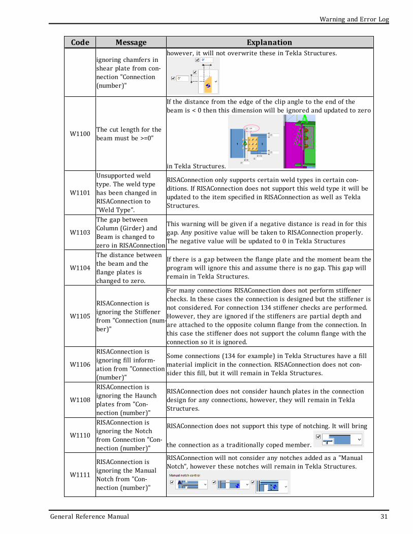
W1007
RISAConnection isignoring the dis-placement of stiffenersfrom connection "Con-nection (number)"
This message will be given if column stiffeners are offset verticallyfrom the beam flange or horizontally from the column web loc-ations. RISAConnection assumes the stiffeners are located at theflange locations. Note that these values are not overwritten in
Tekla Structures.
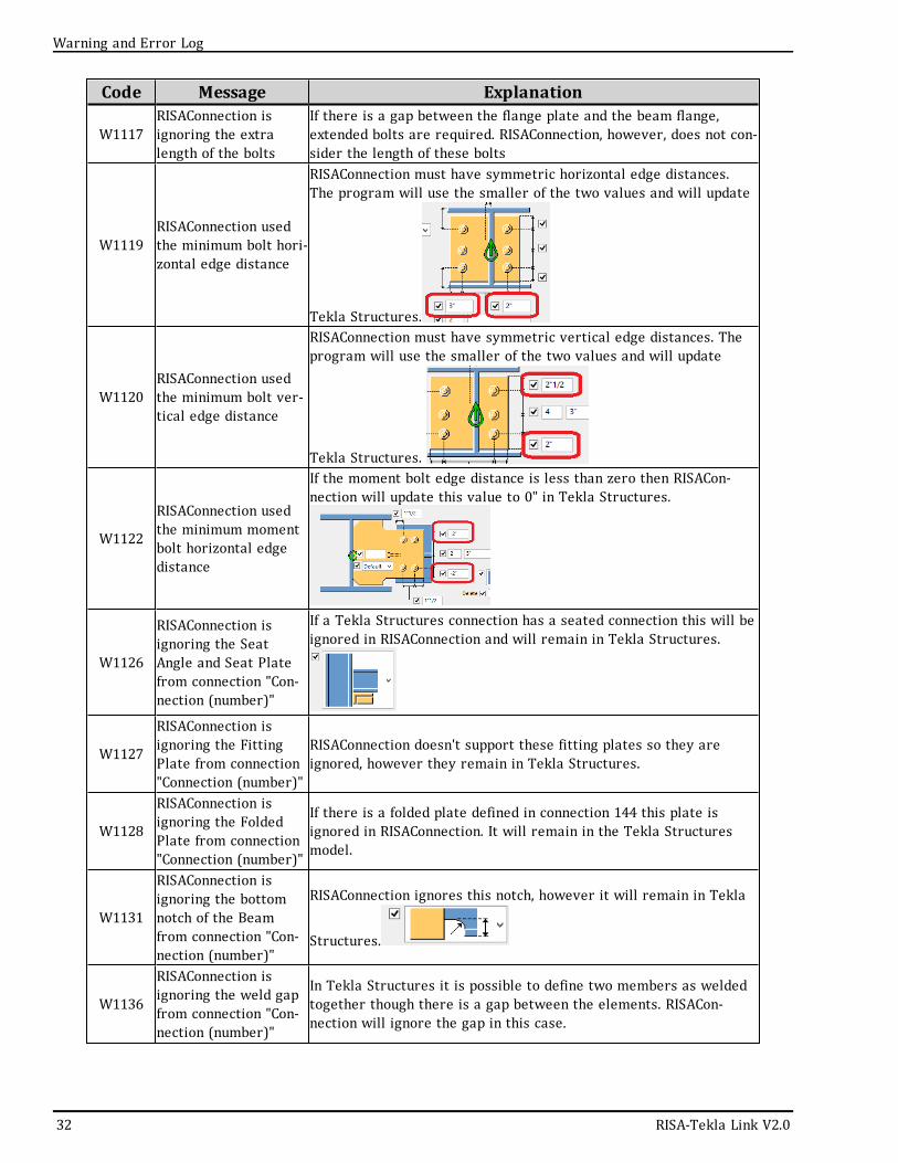
W1008
RISAConnection isignoring the bevel indoubler plates fromFlange Moment Plate(134)
RISAConnection uses fully rectangular doubler plates, but will not
overwrite the Tekla Structures model.
W1009
RISAConnection isignoring holes in dou-bler plates from con-nection "Connection(number)"
RISAConnection assumes the doubler are solid, without the presenceof holes, but will not remove the holes in Tekla Structures.
W1010
RISAConnection isusing the transversestiffener width basedon column shape inconnection "Connection(number)"
RISAConnection requires the transverse stiffener width must matchthe column width. This dimension will be updated in Tekla Struc-tures.
W1011RISAConnection isusing the transverse
If a transverse stiffener is used where the depth dimension is largerthan what will fit the column this message will be given and Tekla
General Reference Manual 29
Code Message Explanationstiffener depth basedon column shape inconnection "Connection(number)"
Structures will be updated with the full depth length.
W1012
RISAConnection isusing the doublerplate width based oncolumn shape inFlange Moment Plate(134)
RISAConnection requires the doubler plate width to be equal to (dcol- 2*tf), However, this will not be overwritten in Tekla Structures.
W1013
RISAConnection isusing the doublerplate depth based oncolumn shape inFlange Moment Plate(134)
The depth of the doubler plate used in RISAConnection comes fromthe AISC Design Guide #13 Figure 4-3 and is defined as dbeam + 2*t-flangeplate + 2*(2.5*kdescol). This is the size that will be used inRISAConnection, but Tekla Structures will not be updated.
W1014
All stiffener platewelds must be thesame in connection"Connection (number)"
RISAConnection requires stiffener plate welds to be the same on allsides. If they are not they will be updated in Tekla Structures to bethe same value.
W1015
All doubler platewelds must be thesame in connection"Connection (number)"
RISAConnection requires doubler plate welds to be the same at thetop and bottom of the plates. They also must be the same on the leftand right. If they are not they will be updated in Tekla Structures tothe value in RISAConnection.
W1016
RISAConnection sup-ports only single filletwelds on doublerplates in connection"Connection (number)"
If all welds are defined as something other than a fillet weld thenthis message will occur. RISAConnection will use fillet welds andupdate the Tekla Structures model.
W1021
The gap betweencolumn/girder and con-nector is not sup-ported inRISAConnection
RISAConnection does not support a gap between a column/girderand the connector element. The Tekla Structures model will also be
updated.
W1031
The connector hasbeen moved verticallyto the supportingbeams K-distance
RISAconnection requires a connection to be at least a distance "k"from the top of the flange in a clip angle, shear tab, or end plate con-nection. This dimension will be updated in Tekla Structures as well.
W1041 RISAConnection is RISAConnection does not support chamfers on shear tab connections,
30 RISA-Tekla Link V2.0
Warning and Error Log
Warning and Error Log
Code Message Explanation
ignoring chamfers inshear plate from con-nection "Connection(number)"
however, it will not overwrite these in Tekla Structures.
W1100 The cut length for thebeam must be >=0"
If the distance from the edge of the clip angle to the end of thebeam is < 0 then this dimension will be ignored and updated to zero
in Tekla Structures.
W1101
Unsupported weldtype. The weld typehas been changed inRISAConnection to"Weld Type".
RISAConnection only supports certain weld types in certain con-ditions. If RISAConnection does not support this weld type it will beupdated to the item specified in RISAConnection as well as TeklaStructures.
W1103
The gap betweenColumn (Girder) andBeam is changed tozero in RISAConnection
This warning will be given if a negative distance is read in for thisgap. Any positive value will be taken to RISAConnection properly.The negative value will be updated to 0 in Tekla Structures
W1104
The distance betweenthe beam and theflange plates ischanged to zero.
If there is a gap between the flange plate and the moment beam theprogram will ignore this and assume there is no gap. This gap willremain in Tekla Structures.
W1105
RISAConnection isignoring the Stiffenerfrom "Connection (num-ber)"
For many connections RISAConnection does not perform stiffenerchecks. In these cases the connection is designed but the stiffener isnot considered. For connection 134 stiffener checks are performed.However, they are ignored if the stiffeners are partial depth andare attached to the opposite column flange from the connection. Inthis case the stiffener does not support the column flange with theconnection so it is ignored.
W1106
RISAConnection isignoring fill inform-ation from "Connection(number)"
Some connections (134 for example) in Tekla Structures have a fillmaterial implicit in the connection. RISAConnection does not con-sider this fill, but it will remain in Tekla Structures.
W1108
RISAConnection isignoring the Haunchplates from "Con-nection (number)"
RISAConnection does not consider haunch plates in the connectiondesign for any connections, however, they will remain in TeklaStructures.
W1110
RISAConnection isignoring the Notchfrom Connection "Con-nection (number)"
RISAConnection does not support this type of notching. It will bring
the connection as a traditionally coped member.
W1111
RISAConnection isignoring the ManualNotch from "Con-nection (number)"
RISAConnection will not consider any notches added as a "ManualNotch", however these notches will remain in Tekla Structures.
General Reference Manual 31
Code Message Explanation
W1117RISAConnection isignoring the extralength of the bolts
If there is a gap between the flange plate and the beam flange,extended bolts are required. RISAConnection, however, does not con-sider the length of these bolts
W1119RISAConnection usedthe minimum bolt hori-zontal edge distance
RISAConnection must have symmetric horizontal edge distances.The program will use the smaller of the two values and will update
Tekla Structures.
W1120RISAConnection usedthe minimum bolt ver-tical edge distance
RISAConnection must have symmetric vertical edge distances. Theprogram will use the smaller of the two values and will update
Tekla Structures.
W1122
RISAConnection usedthe minimum momentbolt horizontal edgedistance
If the moment bolt edge distance is less than zero then RISACon-nection will update this value to 0" in Tekla Structures.
W1126
RISAConnection isignoring the SeatAngle and Seat Platefrom connection "Con-nection (number)"
If a Tekla Structures connection has a seated connection this will beignored in RISAConnection and will remain in Tekla Structures.
W1127
RISAConnection isignoring the FittingPlate from connection"Connection (number)"
RISAConnection doesn't support these fitting plates so they areignored, however they remain in Tekla Structures.
W1128
RISAConnection isignoring the FoldedPlate from connection"Connection (number)"
If there is a folded plate defined in connection 144 this plate isignored in RISAConnection. It will remain in the Tekla Structuresmodel.
W1131
RISAConnection isignoring the bottomnotch of the Beamfrom connection "Con-nection (number)"
RISAConnection ignores this notch, however it will remain in Tekla
Structures.
W1136
RISAConnection isignoring the weld gapfrom connection "Con-nection (number)"
In Tekla Structures it is possible to define two members as weldedtogether though there is a gap between the elements. RISACon-nection will ignore the gap in this case.
32 RISA-Tekla Link V2.0
Warning and Error Log
Warning and Error Log
Code Message Explanation
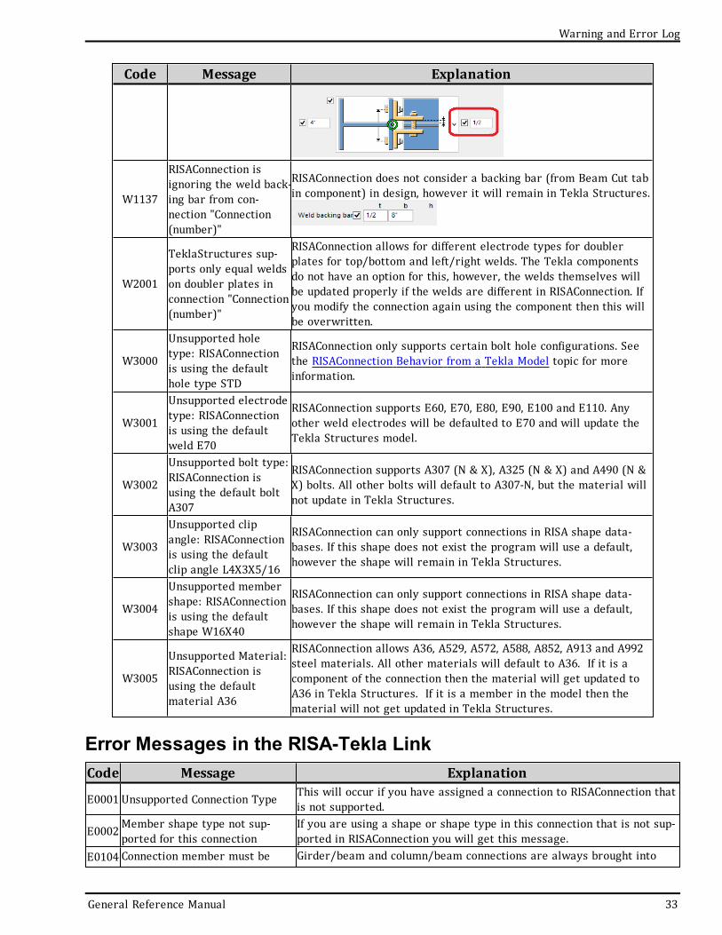
W1137
RISAConnection isignoring the weld back-ing bar from con-nection "Connection(number)"
RISAConnection does not consider a backing bar (from Beam Cut tabin component) in design, however it will remain in Tekla Structures.
W2001
TeklaStructures sup-ports only equal weldson doubler plates inconnection "Connection(number)"
RISAConnection allows for different electrode types for doublerplates for top/bottom and left/right welds. The Tekla componentsdo not have an option for this, however, the welds themselves willbe updated properly if the welds are different in RISAConnection. Ifyou modify the connection again using the component then this willbe overwritten.
W3000
Unsupported holetype: RISAConnectionis using the defaulthole type STD
RISAConnection only supports certain bolt hole configurations. Seethe RISAConnection Behavior from a Tekla Model topic for moreinformation.
W3001
Unsupported electrodetype: RISAConnectionis using the defaultweld E70
RISAConnection supports E60, E70, E80, E90, E100 and E110. Anyother weld electrodes will be defaulted to E70 and will update theTekla Structures model.
W3002
Unsupported bolt type:RISAConnection isusing the default boltA307
RISAConnection supports A307 (N & X), A325 (N & X) and A490 (N &X) bolts. All other bolts will default to A307-N, but the material willnot update in Tekla Structures.
W3003
Unsupported clipangle: RISAConnectionis using the defaultclip angle L4X3X5/16
RISAConnection can only support connections in RISA shape data-bases. If this shape does not exist the program will use a default,however the shape will remain in Tekla Structures.
W3004
Unsupported membershape: RISAConnectionis using the defaultshape W16X40
RISAConnection can only support connections in RISA shape data-bases. If this shape does not exist the program will use a default,however the shape will remain in Tekla Structures.
W3005
Unsupported Material:RISAConnection isusing the defaultmaterial A36
RISAConnection allows A36, A529, A572, A588, A852, A913 and A992steel materials. All other materials will default to A36. If it is acomponent of the connection then the material will get updated toA36 in Tekla Structures. If it is a member in the model then thematerial will not get updated in Tekla Structures.
Error Messages in the RISA-Tekla LinkCode Message Explanation
E0001 Unsupported Connection Type This will occur if you have assigned a connection to RISAConnection thatis not supported.
E0002Member shape type not sup-ported for this connectionIf you are using a shape or shape type in this connection that is not sup-ported in RISAConnection you will get this message.
E0104 Connection member must be Girder/beam and column/beam connections are always brought into
General Reference Manual 33
Code Message Explanation
orthogonal (within 15 degrees)for RISAConnection
RISAConnection orthogonally. If the connection slope, skew or rotation isnot within 15 degrees from orthogonal then the connection will not goto RISAConnection.
E0201Member center line must alignfor a valid RISAConnection
For columns the vertical (or horizontal) position must be defined as"Middle" so that the beam is centered on the column. For beams theplane position must be defined as "Middle". If these options are not setto be centered the connection will not go to RISAConnection.
E0202 Invalid member rotation for avalid RISAConnection
For girder/beam connections the girder rotation position must be "Top"or "Below". For column/beam or girder/beam connections the beamrotation position must be "Top" or "Below". If these options are set toanything else they will not go to RISAConnection.
E0203 Column orientation not sup-ported for this connectionThe flange-plated moment connection is only supported in RISACon-nection if the connection is attached to the column flange.
E0204Connection 134 is supportedbetween column and beam con-nection only
Flange-plated moment connections are not supported in RISAConnectionfor girder/beam connections.
E0401Requested clip angle con-figuration is not supported byRISAConnection
If there is not a single or double clip angle configuration on this con-nection this message will be given. Deleting both clip angles will givethis message.
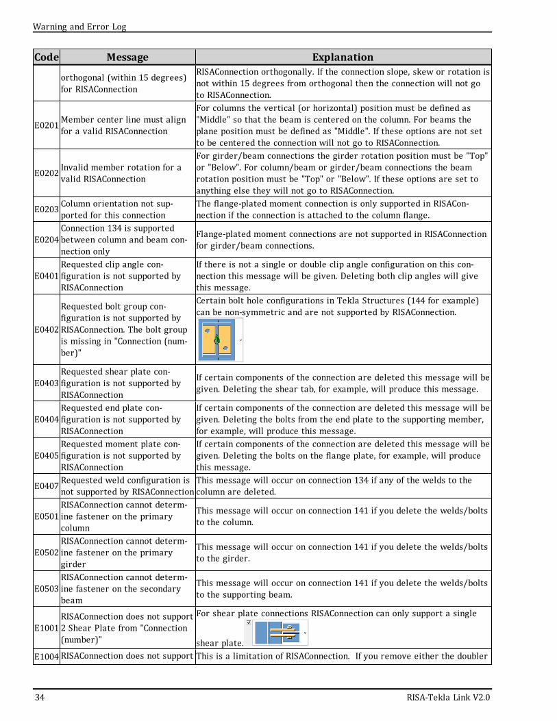
E0402
Requested bolt group con-figuration is not supported byRISAConnection. The bolt groupis missing in "Connection (num-ber)"
Certain bolt hole configurations in Tekla Structures (144 for example)can be non-symmetric and are not supported by RISAConnection.
E0403Requested shear plate con-figuration is not supported byRISAConnection
If certain components of the connection are deleted this message will begiven. Deleting the shear tab, for example, will produce this message.
E0404Requested end plate con-figuration is not supported byRISAConnection
If certain components of the connection are deleted this message will begiven. Deleting the bolts from the end plate to the supporting member,for example, will produce this message.
E0405Requested moment plate con-figuration is not supported byRISAConnection
If certain components of the connection are deleted this message will begiven. Deleting the bolts on the flange plate, for example, will producethis message.
E0407 Requested weld configuration isnot supported by RISAConnectionThis message will occur on connection 134 if any of the welds to thecolumn are deleted.
E0501RISAConnection cannot determ-ine fastener on the primarycolumn
This message will occur on connection 141 if you delete the welds/boltsto the column.
E0502RISAConnection cannot determ-ine fastener on the primarygirder
This message will occur on connection 141 if you delete the welds/boltsto the girder.
E0503RISAConnection cannot determ-ine fastener on the secondarybeam
This message will occur on connection 141 if you delete the welds/boltsto the supporting beam.
E1001RISAConnection does not support2 Shear Plate from "Connection(number)"
For shear plate connections RISAConnection can only support a single
shear plate.E1004 RISAConnection does not support This is a limitation of RISAConnection. If you remove either the doubler
34 RISA-Tekla Link V2.0
Warning and Error Log
Warning and Error Log
Code Message Explanationconnections with both trans-verse stiffeners and doublerplates in "Connection (number)"
plates or the stiffeners and send it back to RISAConnection then you canget a design.
E1012 Bolt groups must be uniform andsymmetric for RISAConnection
If you delete bolts from a bolt configuration or have non-uniform ver-tical or horizontal spacing between bolts then you will get this message.
E1018 RISAConnection does not supportstaggered bolt configuration.
Connections with bolt configurations that are not rectangular and ortho-
gonal will not be brought into RISAConnection.
E1021 Bolts must be concentric withthe connection.
Where there are bolts on either side of a centerline of a connecting ele-
ment the bolts must be centered on that element.
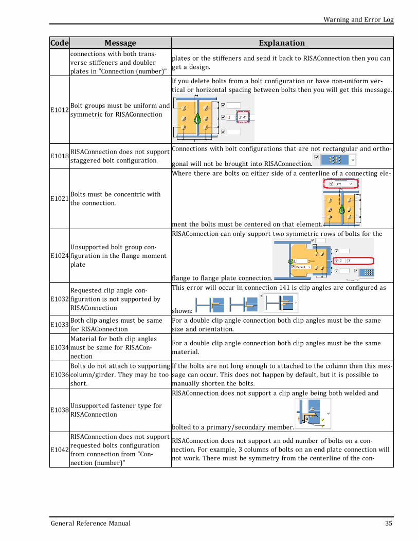
E1024Unsupported bolt group con-figuration in the flange momentplate
RISAConnection can only support two symmetric rows of bolts for the
flange to flange plate connection.
E1032Requested clip angle con-figuration is not supported byRISAConnection
This error will occur in connection 141 is clip angles are configured as
shown:
E1033 Both clip angles must be samefor RISAConnectionFor a double clip angle connection both clip angles must be the samesize and orientation.
E1034Material for both clip anglesmust be same for RISACon-nection
For a double clip angle connection both clip angles must be the samematerial.
E1036Bolts do not attach to supportingcolumn/girder. They may be tooshort.
If the bolts are not long enough to attached to the column then this mes-sage can occur. This does not happen by default, but it is possible tomanually shorten the bolts.
E1038 Unsupported fastener type forRISAConnection
RISAConnection does not support a clip angle being both welded and
bolted to a primary/secondary member.
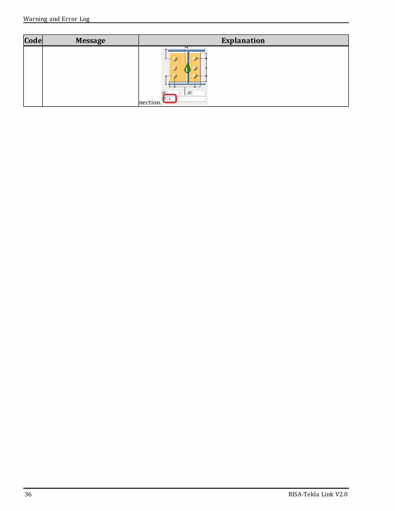
E1042
RISAConnection does not supportrequested bolts configurationfrom connection from "Con-nection (number)"
RISAConnection does not support an odd number of bolts on a con-nection. For example, 3 columns of bolts on an end plate connection willnot work. There must be symmetry from the centerline of the con-
General Reference Manual 35
Code Message Explanation
nection.
36 RISA-Tekla Link V2.0
Warning and Error Log
Technical Support
Technical SupportTechnical support is an important part of the RISA package. There is no charge for technical support for alllicensed owners of the current versions of our software.
Hours: 6AM to 5PM Pacific Standard Time, Monday through Friday (excluding holidays)
Before contacting technical support, you should typically do the following:
1. Please search the Help File or General Reference Manual. Most questions asked about RISA products areanswered in the Help File or General Reference Manual. Use the table of contents or index to find specifictopics and appropriate sections.
2. If you have access to the Internet, you can visit our website at www.risa.com and check out our Down-loads and Support section for release notes, updates, downloads, and frequently asked questions. We listknown issues and product updates that you can download. So, if you think the program is in error youshould see if the problem is listed and make sure you have the latest release. The FAQ (FrequentlyAsked Questions) section may also address your question.
3. Make sure you understand the problem, and make sure your question is related to the program or struc-tural modeling. Technical Support does not include engineering consulting.
4. Take a few minutes to experiment with the problem to try to understand and solve it.
For all modeling support questions, please be prepared to send us your model input file via email. We often willneed to have your model in hand to debug a problem or answer your questions.
Email: [email protected]: This method is the best way to send us a model you would like help with. Make sureyou tell us your name, company name, Key ID, phone number, and give a sufficient problem description.
Phone Support:(949) 951-5815: You can also call. But keep in mind that this works best only if your question isnot model specific and therefore doesn't require us to look at your file.
General Reference Manual 37

Index
Index
General Reference Manual i
A
Application Interface 5
B
Before You Begin 1
Bolt Hole Configuration 21
Bolt Hole Mapping 26
Bolt Mapping 24
C
Completing the Tekla Model 9
Configuring Connections 10
Connection Grouping 14
Connection Results Viewing in Tekla 11
Copyright 2
E
Error Messages 33
F
Folder Structure 8
G
Graphical Results View 7
Grouping Behavior 15
I
Installation 4
L
License Agreement 2
Loading 17
M
Mapping 21
Material Mapping 25
O
Overview 1
P
Program Capabilities 1
R
RISA Tekla Link Browser 6
RISAConnection Behavior 14
Round-tripping 20
S
Sending the Model to RISAConnection 9
Solving Connections 17
Solving in RISAConnection 10
System Requirements 2
T
Technical Support 4, 37
Toolbar 5
V
Viewing Results (in RISAConnection) 18
Viewing Results (in Tekla) 19
W
Warning Messages 28
Weld Mapping 25