tekla structures 2017i€¦ · link tekla structures with an analysis application (page 12) select...
TRANSCRIPT

Tekla Structures 2017iAnalysis
September 2017
©2017 Trimble Solutions Corporation

Contents
1 Get started with analysis..............................................................71.1 What is an analysis model................................................................................7
Analysis model objects............................................................................................................91.2 About analysis applications...........................................................................121.3 Link Tekla Structures with an analysis application.................................... 121.4 Structural analysis workflow in Tekla Structures....................................... 13
2 Create and group loads...............................................................152.1 Set the load modeling code............................................................................17
Use non-standard load combination factors..................................................................... 172.2 Group loads together......................................................................................18
Create or modify a load group............................................................................................. 19Set the current load group................................................................................................... 20Load group compatibility......................................................................................................20Delete a load group............................................................................................................... 21
2.3 Create loads..................................................................................................... 22Define the properties of a load............................................................................................22
Load magnitude................................................................................................................23Load form..........................................................................................................................24
Create a point load................................................................................................................ 25Create a line load................................................................................................................... 25Create an area load............................................................................................................... 26Create a uniform load........................................................................................................... 27Create a temperature load or a strain................................................................................ 27Create wind loads.................................................................................................................. 28
Wind load examples.........................................................................................................29
3 Distribute and modify loads.......................................................323.1 Attach loads to parts or locations.................................................................323.2 Apply loads to parts........................................................................................ 33
Define load-bearing parts by name.....................................................................................33Define load-bearing parts by selection filter...................................................................... 34Bounding box of a load.........................................................................................................34
3.3 Change the loaded length or area of a load.................................................353.4 Modify the distribution of a load.................................................................. 363.5 Modify the location or layout of a load........................................................ 383.6 Move a load end or corner using handles.................................................... 40
4 Work with loads and load groups.............................................. 414.1 Scale loads in model views.............................................................................41
2

4.2 Check loads and load groups......................................................................... 42Inquire load properties......................................................................................................... 42Find out to which load group a load belongs.....................................................................43Find out which loads belong to a load group.....................................................................44Check loads using reports.................................................................................................... 44
4.3 Move loads to another load group................................................................ 454.4 Export load groups.......................................................................................... 454.5 Import load groups......................................................................................... 46
5 Create analysis models............................................................... 475.1 Define basic properties for an analysis model............................................ 475.2 Objects included in analysis models.............................................................48
Analysis model creation method......................................................................................... 49Analysis model filter.............................................................................................................. 49
5.3 Select the analysis application...................................................................... 505.4 Create an analysis model............................................................................... 51
Create an analysis model of entire physical and load models.........................................51Create an analysis model for specific parts and loads......................................................52Create a modal analysis model............................................................................................52
6 Modify analysis models.............................................................. 546.1 Check which objects are included in an analysis model............................ 546.2 Modify the properties of an analysis model................................................ 55
Change the creation method of an analysis model...........................................................56Define the axis settings of an analysis model....................................................................56Define seismic loads for an analysis model....................................................................... 57Define modal masses for an analysis model..................................................................... 58Define the design properties of an analysis model...........................................................59Define analysis model rules................................................................................................. 59
Open the Analysis Model Rules dialog box................................................................... 59Add an analysis model rule.............................................................................................60Organize analysis model rules........................................................................................61Delete analysis model rules............................................................................................ 61Test analysis model rules................................................................................................ 61Save analysis model rules............................................................................................... 62
6.3 Add objects to an analysis model..................................................................626.4 Remove objects from an analysis model......................................................626.5 Create an analysis node................................................................................. 63
Analysis node colors..............................................................................................................636.6 Create a rigid link............................................................................................ 646.7 Merge analysis nodes..................................................................................... 656.8 Copy an analysis model.................................................................................. 666.9 Delete an analysis model............................................................................... 67
7 Modify analysis parts.................................................................. 687.1 About analysis part properties......................................................................687.2 Modify the properties of an analysis part....................................................69
3

7.3 Define support conditions............................................................................. 71Define the support conditions of a part end......................................................................71Define the support conditions of a plate............................................................................72Support condition symbols.................................................................................................. 73
7.4 Define design properties for analysis parts.................................................74Omit analysis parts from design..........................................................................................76Define the buckling lengths of a column............................................................................ 76
Kmode options................................................................................................................. 777.5 Define the location of analysis parts............................................................78
Define or modify the axis location of an analysis part......................................................79Define offsets for an analysis part.......................................................................................80Reset the editing of analysis parts.......................................................................................80
7.6 Copy an analysis part......................................................................................817.7 Delete an analysis part...................................................................................82
8 Combine loads..............................................................................838.1 About load combinations............................................................................... 838.2 Create load combinations automatically.....................................................848.3 Create a load combination.............................................................................858.4 Modify a load combination............................................................................ 868.5 Copy load combinations between analysis models.................................... 87
Save load combinations for later use..................................................................................87Copy load combinations from another analysis model....................................................87
8.6 Delete load combinations.............................................................................. 88
9 Work with analysis and design models.....................................899.1 Check warnings about an analysis model....................................................899.2 Export an analysis model............................................................................... 909.3 Merge analysis models using analysis applications................................... 91
Merge analysis models using SAP2000...............................................................................91How to merge a Tekla Structures analysis model with a model in SAP2000..................92Reset merged analysis models............................................................................................ 93
9.4 Save analysis results.......................................................................................93Save analysis results as user-defined attributes of parts................................................. 94
9.5 View the analysis results of a part................................................................ 949.6 Show analysis class in model views.............................................................. 959.7 Show analysis bar, member, and node numbers........................................ 959.8 Show the utilization ratio of parts................................................................ 96
10 Analysis and design settings...................................................... 9810.1 Load group properties.................................................................................... 9810.2 Load properties............................................................................................. 100
Point load properties.......................................................................................................... 100Line load properties............................................................................................................ 101Area load properties........................................................................................................... 102Uniform load properties..................................................................................................... 102Temperature load properties............................................................................................. 103
4

Wind load properties.......................................................................................................... 104Load panel settings............................................................................................................. 105
10.3 Load combination properties...................................................................... 107Load modeling code options..............................................................................................107Load combination factors...................................................................................................107Load combination types..................................................................................................... 108
10.4 Analysis model properties........................................................................... 11010.5 Analysis part properties............................................................................... 116
Analysis class options and colors...................................................................................... 126Analysis axis options........................................................................................................... 129
10.6 Analysis node properties..............................................................................13110.7 Analysis rigid link properties....................................................................... 13210.8 Analysis bar position properties................................................................. 13410.9 Analysis area position properties............................................................... 13410.10 Analysis area edge properties..................................................................... 135
11 Disclaimer...................................................................................137
5

6

1 Get started with analysis
This section explains some basic concepts and procedures you need to knowto get started with structural analysis in Tekla Structures.
Click the links below to find out more:
What is an analysis model (page 7)
About analysis applications (page 12)
Link Tekla Structures with an analysis application (page 12)
Structural analysis workflow in Tekla Structures (page 13)
1.1 What is an analysis modelWhen you use Tekla Structures to model, analyze, and design structures, youwill become familiar with the following concepts:
A physical model is a structural 3D model that includes the parts you createusing Tekla Structures, and information related to them. Each part in thephysical model will exist in the completed structure.
Get started with analysis 7 What is an analysis model

The load model contains information about loads and load groups that act onphysical model parts. It also contains information about the building code thatTekla Structures uses in the load combination process.
An analysis model is a structural model that is created from a physical model. Itis used for analyzing structural behavior and load bearing, and for design.
Get started with analysis 8 What is an analysis model
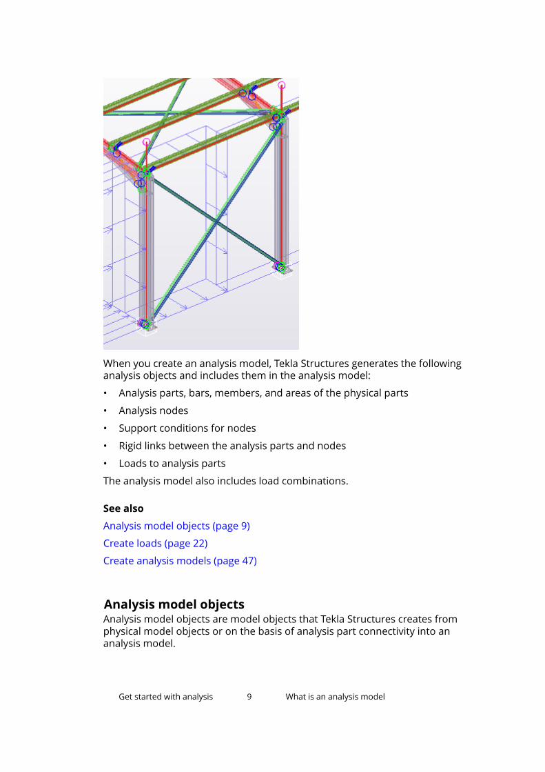
When you create an analysis model, Tekla Structures generates the followinganalysis objects and includes them in the analysis model:
• Analysis parts, bars, members, and areas of the physical parts
• Analysis nodes
• Support conditions for nodes
• Rigid links between the analysis parts and nodes
• Loads to analysis parts
The analysis model also includes load combinations.
See also
Analysis model objects (page 9)
Create loads (page 22)
Create analysis models (page 47)
Analysis model objectsAnalysis model objects are model objects that Tekla Structures creates fromphysical model objects or on the basis of analysis part connectivity into ananalysis model.
Get started with analysis 9 What is an analysis model

Object DescriptionAnalysis part A representation of a physical part in an analysis
model.
In different analysis models, a physical part isrepresented by different analysis parts.
Analysis bar An analysis object that Tekla Structures createsfrom a physical part (beam, column, or brace) orfrom a part segment.
Tekla Structures creates more than one analysisbar from a physical part if:
• The part is a polybeam
• The part cross section changes non-linearly
An analysis bar consists of one or more analysismembers.
Analysis member An analysis object that Tekla Structures createsbetween two nodes.
Tekla Structures creates more than one analysismember from an analysis bar if the bar intersectswith other bars and needs to be split.
Every physical part that you include in an analysismodel produces one or more analysis members. Asingle physical part produces several analysismembers if the physical part intersects with otherphysical parts. Tekla Structures splits the physicalpart at the intersection points of the analysis axes.For example, a physical model beam that supportstwo other beams is split into three analysismembers between nodes.
Analysis area An analysis object that represents a plate, slab, orpanel in an analysis model.
Analysis element An analysis object that the analysis applicationcreates from an analysis area.
The analysis application creates an element meshthat includes several analysis elements.
Get started with analysis 10 What is an analysis model

Object DescriptionAnalysis node An analysis object that Tekla Structures creates at a
defined point in an analysis model on the basis ofanalysis part connectivity.
Tekla Structures creates analysis nodes at:
• The ends of members
• The intersection points of analysis axes
• The corners of elements
Rigid link An analysis object that connects two analysisnodes so that they do not move in relation to eachother.
Rigid links have the following properties in TeklaStructures analysis models:
• Profile = PL300.0*300.0
• Material = RigidlinkMaterial
• Density = 0.0
• Modulus of elasticity = 100*109 N/m2
• Poisson’s ratio = 0.30
• Thermal dilatation coefficient = 0.0 1/K
The analysis application that you use may modelrigid links by dedicated rigid link objects.
Rigid diaphragm An analysis object that connects more than twoanalysis nodes that move with exactly the samerotation and translation.
Some analysis applications work on analysis members whereas others workon analysis bars. This also affects how analysis models are shown in TeklaStructures model views. Either member numbers or bar numbers are shown.
See also
Create an analysis node (page 63)
Create a rigid link (page 64)
Modify analysis parts (page 68)
Objects included in analysis models (page 48)
Show analysis bar, member, and node numbers (page 95)
Get started with analysis 11 What is an analysis model

1.2 About analysis applicationsAn analysis application is an external analysis and design software that you usewith Tekla Structures to analyze and design structures.
The analysis application calculates the forces, moments, and stresses on thestructures. It also calculates the displacements, deflections, rotations, andwarping of objects under various loading conditions.
Tekla Structures links with a number of analysis applications and also supportsexport with them in several formats. The analysis application in which you runstructural analysis uses data from the Tekla Structures analysis models togenerate analysis results.
To analyze Tekla Structures analysis models with an analysis application, youneed to install a direct link between Tekla Structures and the analysisapplication.
See also
Link Tekla Structures with an analysis application (page 12)
Select the analysis application (page 50)
1.3 Link Tekla Structures with an analysis applicationTo use an external analysis application with Tekla Structures analysis models,you need to install a direct link between Tekla Structures and the analysisapplication.
Before you start, ensure that you have:
• Access to the Tekla User Assistance service
• Administrator rights to your computer
1. Log in to your computer as an administrator.
2. Install Tekla Structures if you do not already have it installed.
3. Install the analysis application if you do not already have it installed.
4. Log in to the Tekla User Assistance service and browse for the linkinstallation instructions in Support Articles --> Analysis and Design .
5. Click an appropriate article, for example, Linking Tekla Structures withSAP2000.
6. Follow the instructions in the support article to download the link for theanalysis application.
7. If needed, install the IFC and CIS/2 formats as advised in the supportarticle.
Get started with analysis 12 About analysis applications

NOTE If you need to uninstall and reinstall Tekla Structures and/or the analysisapplication for some reason, you will also need to reinstall the link afterinstalling Tekla Structures and/or the analysis application.
See also
About analysis applications (page 12)
1.4 Structural analysis workflow in Tekla StructuresHere is one example of the steps you may need to take when you analyzestructures using Tekla Structures. Depending on your project, some of thesteps may not be needed, some may be repeated or carried out in a differentorder.
Before you start, create the main load-bearing parts that you need to analyze.There is no need to detail or create connections at this stage. If you have adetailed model, or more parts in the physical model than you need to analyze,you can exclude these parts from the analysis.
To carry out a structural analysis in Tekla Structures:
1. Set the load modeling code (page 16).
2. Create load groups (page 18).
3. Create loads (page 22).
4. Define the basic analysis model properties (page 47).
5. If you do not want to create an analysis model of the entire physical andload models, define which objects to include in the analysis model(page 48).
6. Select the analysis application (page 50).
7. Create a new analysis model (page 50) using the default analysis modelproperties.
8. Check the analysis model and analysis parts (page 54) in a TeklaStructures model view.
9. Export the analysis model to the analysis application so as to run a test inthe analysis application.
10. If needed, modify the analysis model (page 54) or analysis parts(page 68) or their properties. For example, you can:
• Define the support conditions (page 71) for analysis parts, and forconnections if you have them.
• Define other analysis properties for individual analysis parts.
• Define design properties.
Get started with analysis 13 Structural analysis workflow in Tekla Structures

• Add (page 63), move, and merge (page 65) analysis nodes.
• Create rigid links (page 64).
• Add (page 62) or remove (page 62) parts and/or loads.
11. If needed, create alternative or sub-analysis models.
12. Create load combinations (page 83).
13. Export the analysis model (page 90) to the analysis application and runthe analysis.
14. If needed, add special loads and other required settings in the analysisapplication.
15. If needed, use the analysis application to postprocess the analysis modelor analysis results. For example, you can change part profiles.
16. Import the analysis results to Tekla Structures, examine (page 94) them,and use them, for example, in connection design.
17. If the analysis results required changes in part profiles, import thechanges to Tekla Structures.
See also
Save analysis results (page 93)
Get started with analysis 14 Structural analysis workflow in Tekla Structures
2 Create and group loads
This section introduces the different types of loads available in TeklaStructures and explains how to create and group them.
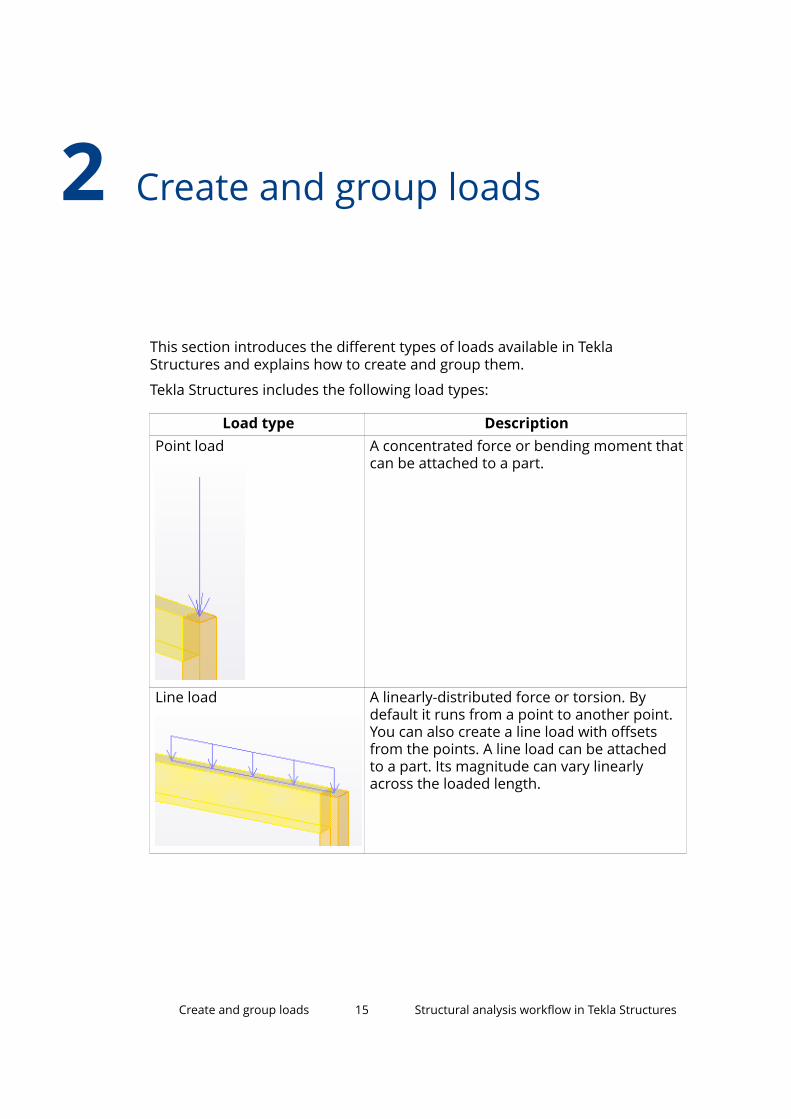
Tekla Structures includes the following load types:
Load type DescriptionPoint load A concentrated force or bending moment that
can be attached to a part.
Line load A linearly-distributed force or torsion. Bydefault it runs from a point to another point.You can also create a line load with offsetsfrom the points. A line load can be attachedto a part. Its magnitude can vary linearlyacross the loaded length.
Create and group loads 15 Structural analysis workflow in Tekla Structures

Load type DescriptionArea load A linearly-distributed force bounded by a
triangle or quadrangle. You do not have tobind the boundary of the area to parts.
Uniform load A uniformly-distributed force bounded by apolygon. You do not have to bind the polygonto parts. Uniform loads can have openings.
Wind load Area loads defined by pressure factors, alongthe height of and on all sides of a building.
Temperature load • A uniform change in temperature that isapplied to specified parts and that causesaxial elongation in parts.
• A temperature difference between twosurfaces of a part that causes the part tobend.
Strain An initial axial elongation or shrinkage of apart.
To ensure that load analysis is correct, use area and uniform loads for loads onfloors. For example, when the layout of beams changes, Tekla Structuresrecalculates the loads to the beams. It will not do this if you use point or lineloads on individual beams. Tekla Structures also distributes area and uniformloads automatically if they act on parts that have openings.
See also
Set the load modeling code (page 16)
Group loads together (page 18)
Create loads (page 22)
Load properties (page 100)
Create and group loads 16 Set the load modeling code

2.1 Set the load modeling codeLoad modeling code settings determine the building code, safety factors, andload group types that Tekla Structures uses in the load combination process.
NOTE You should not need to change these settings during the project. Ifyou change the settings, you will also need to change the load grouptypes and check the load combinations.
To set the load modeling code and to use the standard building code specificload combination factors:
1. On the File menu, click Settings --> Options , and go to the Loadmodeling settings.
2. On the Current code tab, select a code from the Load modeling codelist.
3. Check the load combination factors on the appropriate tab.
4. If you use the Eurocode, enter the reliability class factor and select theformula to be used on the Eurocode tab.
5. Click OK.
See also
Load modeling code options (page 107)
Load combination factors (page 107)
Use non-standard load combination factors (page 17)
Use non-standard load combination factorsIf necessary, you can change the values of building code specific loadcombination factors and create your own settings to be used in the loadcombination process.
NOTE You should not need to change these settings during the project. Ifyou change the settings, you will also need to change the load grouptypes and check the load combinations.
1. On the File menu, click Settings --> Options , and go to the Loadmodeling settings.
2. On the Current code tab, select a code from the Load modeling code listthat is the most appropriate to your needs.
3. Change the load combination factors on the appropriate tab.
4. Save the settings using a new name.
a. Enter a name in the box next to the Save as button.
Create and group loads 17 Set the load modeling code

b. Click Save as.
Tekla Structures saves the settings in the \attributes folder underthe current model folder with the file name extension .opt.
To later use the saved settings, select the name of the settings file fromthe Load list, and then click Load.
5. Click OK.
See also
Load combination factors (page 107)
Set the load modeling code (page 16)
2.2 Group loads togetherEach load in a Tekla Structures model has to belong to a load group. A loadgroup is a set of loads and loadings that are caused by the same action and towhich you want to refer collectively. Loads that belong to the same load groupare treated alike during the load combination process.
Tekla Structures assumes that all loads in a load group:
• Have the same partial safety and other combination factors
• Have the same action direction
• Occur at the same time and all together
You can include as many loads as you like in a load group, of any load type.
You need to create load groups because Tekla Structures creates loadcombinations on the basis of load groups. We recommend that you define theload groups before you create loads.
See also
Create or modify a load group (page 18)
Set the current load group (page 19)
Load group compatibility (page 20)
Delete a load group (page 21)
Load group properties (page 98)
Work with loads and load groups (page 41)
Combine loads (page 83)
Create and group loads 18 Group loads together

Create or modify a load groupYou can create a load group by adding a new group or by modifying the defaultload group. You can modify any existing load group in the same way as thedefault load group.
Before you start, ensure that you have the appropriate load modeling codeselected in File menu --> Settings --> Options --> Load modeling --> Currentcode. See Set the load modeling code (page 16).
1. On the Analysis & design tab, click Load groups.
2. In the Load Groups dialog box, do one of the following:
• Click Add to create a new load group.
• Select the default load group from the list to modify it.
• Select an existing load group from the list to modify it.
3. Click the load group name to modify it.
4. Click the load group type and select a type from the list.
5. Click the load group direction to modify it.
6. To indicate compatibility with existing load groups:
a. In the Compatible column, enter the number you have used for theload groups that are compatible with this load group.
b. In the Incompatible column, enter the number you have used for theload groups that are incompatible with this load group.
7. Click the load group color and select a color from the list.
Tekla Structures uses this color when it shows the loads of this load groupin the model views.
8. Click OK to close the dialog box.
See also
Load group properties (page 98)
Set the current load group (page 19)
Load group compatibility (page 20)
Delete a load group (page 21)
Work with loads and load groups (page 41)
Create and group loads 19 Group loads together

Set the current load groupYou can define one of the load groups as current. Tekla Structures adds all newloads you create in the current load group.
Before you start, create at least one load group.
1. On the Analysis & design tab, click Load groups.
2. In the Load Groups dialog box:
a. Select a load group.
b. Click Set current.
Tekla Structures marks the current load group with the @ character inthe Current column.
c. Click OK to close the dialog box.
See also
Create or modify a load group (page 18)
Load group properties (page 98)
Load group compatibilityWhen Tekla Structures creates load combinations for structural analysis, itfollows the building code you select in File menu --> Settings --> Options -->Load modeling --> Current code.
To accurately combine loads which have the same load group type, you needto use compatibility indicators (numbers) to identify which load groups:
• Can occur at the same time (are compatible)
• Exclude each other (are incompatible)
Compatible load groups can act together or separately. They can actually beone single loading, for example, a live loading that needs to be split in partsthat act on different spans of a continuous beam. Tekla Structures thenincludes none, one, several, or all of the compatible load groups in a loadcombination.
Incompatible load groups always exclude each other. They cannot occur at thesame time. For example, a wind loading from the x direction is incompatiblewith a wind loading from the y direction. In load combinations Tekla Structuresonly takes into account one load group in an incompatible grouping at a time.
Tekla Structures automatically applies basic compatibility facts, such as self-weight being compatible with all other loads, or live loads being compatiblewith wind load.
Create and group loads 20 Group loads together

Tekla Structures does not combine loads in the x direction with those in the ydirection.
Compatibility indicators are all 0 by default. This indicates that Tekla Structurescombines the load groups as defined in the building code.
See also
Load group properties (page 98)
Create or modify a load group (page 18)
Combine loads (page 83)
Set the load modeling code (page 16)
Delete a load groupYou can delete one or several load groups at a time.
WARNING When you delete a load group, Tekla Structures also deletes allthe loads in the load group.
If you try to delete the only load group, Tekla Structures will warnyou. At least one load group must exist.
1. On the Analysis & design tab, click Load groups.
2. In the Load Groups dialog box:
a. Select the load group you want to delete.
To select multiple load groups, hold down the Ctrl or Shift key.
b. Click Delete.
3. If there are loads in any of the deleted load groups, Tekla Structuresdisplays a warning dialog box.
Do one of the following:
• Click Cancel to not delete the load group and the loads in the loadgroup.
• Click Delete to delete the load group and the loads in the load group.
See also
Group loads together (page 18)
Create or modify a load group (page 18)
Work with loads and load groups (page 41)
Load group properties (page 98)
Create and group loads 21 Group loads together

2.3 Create loadsWhen you create loads, you have two choices: you can set the properties of aload before you create it, or you can modify the properties after you havecreated a load.
NOTE You cannot attach a load to a part after you have created the load.
You can detach a load from a part after you have created the load.
TIP To create loads perpendicular to sloped parts, you can shift the work plane.
Before you start creating loads, define the load groups and set the currentload group.
See also
Define the properties of a load (page 22)
Create a point load (page 25)
Create a line load (page 25)
Create an area load (page 26)
Create a uniform load (page 26)
Create a temperature load or a strain (page 27)
Create wind loads (page 28)
Distribute and modify loads (page 32)
Work with loads and load groups (page 41)
Group loads together (page 18)
Combine loads (page 83)
Define the properties of a loadBefore you create a load, it is a good idea to define or check the loadproperties.
1. On the Analysis & design tab, click Load properties, and then click arelevant load type.
For example, click Area load to define area load properties.
2. In the load properties dialog box:
a. Enter or modify the properties.
• Select a load group.
• Define the load magnitude, and the load form if needed.
Create and group loads 22 Create loads

• Attach the load to a part or to a position.
You cannot attach a load to a part after you have created the load.
You can detach a load from a part after you have created the load.
• Define the load-bearing parts.
• If needed, adjust the loaded length or area.
• If needed, modify the load distribution on the Load panel tab.
b. Click OK to save the properties.
Tekla Structures uses these properties when you create new loads of this type.
See also
Load properties (page 100)
Load magnitude (page 23)
Load form (page 24)
Distribute and modify loads (page 32)
Group loads together (page 18)
Load magnitudeLoad magnitude can occur in x, y, and z directions. The coordinate system isthe same as the current work plane. Positive coordinates indicate a positiveload direction.
For example, when you create loads perpendicular to sloped parts, shifting thework plane helps you to place loads accurately.
Some load types can have several magnitude values. For example, themagnitude of line loads may vary along the loaded length.
In the load properties dialog boxes, the following letters denote differentmagnitude types:
Create and group loads 23 Create loads

• P is for a force acting on a position, along a line, or across an area.
• M is for bending moments acting on a position or along a line.
• T is for torsional moments acting along a line.
The units depend on the settings in File menu --> Settings --> Options -->Units and decimals.
In the load properties dialog boxes, the numbering of the magnitude valuesrelates to the order in which you pick points when you create loads.
See also
Load properties (page 100)
Load formDistributed loads (line and area loads) can have different load forms.
The load form of a line load defines how the load magnitude varies along theloaded length. The options are:
Option DescriptionThe load magnitude is uniform across the loadedlength.
The load has different magnitudes at the ends of theloaded length. The magnitude changes linearlybetween the ends.The load magnitude changes linearly, from zero at theends of the loaded length, to a fixed value in themiddle of the loaded length.The load magnitude changes linearly, from zero at oneend of the loaded length, through two (different)values, back to zero at the other end.
The load form of an area load defines the shape of the loaded area. It can be:
Option DescriptionQuadrangular
Triangular
Create and group loads 24 Create loads

See also
Line load properties (page 101)
Area load properties (page 102)
Create a point loadYou can create a concentrated force or a bending moment acting on aposition.
Before you start, shift the work plane if you need to create a loadperpendicular to a sloped part.
1. On the Analysis & design tab, click Load properties --> Point load .
2. In the Point Load Properties dialog box:
a. Enter or modify the load properties.
b. On the Distribution tab, select whether you want to attach the loadto a part.
c. Click OK to save the changes.
3. On the Analysis & design tab, click Load --> Point load .
4. If you selected to attach the load to a part, select the part.
5. Pick the position of the load.
See also
Point load properties (page 100)
Define the properties of a load (page 22)
Attach loads to parts or locations (page 32)
Create a line loadYou can create a linearly-distributed force or torsion between two points youpick.
Before you start, shift the work plane if you need to create a loadperpendicular to a sloped part.
1. On the Analysis & design tab, click Load properties --> Line load .
2. In the Line Load Properties dialog box:
a. Enter or modify the load properties.
b. On the Distribution tab, select whether you want to attach the loadto a part.
c. Click OK to save the changes.
Create and group loads 25 Create loads

3. On the Analysis & design tab, click Load --> Line load .
4. If you selected to attach the load to a part, select the part.
5. Pick the start point of the load.
6. Pick the end point of the load.
See also
Line load properties (page 101)
Define the properties of a load (page 22)
Attach loads to parts or locations (page 32)
Create an area loadArea loads affect triangular or quadrangular areas. If you select the triangularload form, the points you pick define the loaded area. To create aquadrangular load form, pick three points, and Tekla Structures automaticallydetermines the fourth corner point.
Before you start, shift the work plane if you need to create a loadperpendicular to a sloped part.
1. On the Analysis & design tab, click Load properties --> Area load .
2. In the Area Load Properties dialog box:
a. Enter or modify the load properties.
b. On the Distribution tab, select whether you want to attach the loadto a part.
c. Click OK to save the changes.
3. On the Analysis & design tab, click Load --> Area load .
4. If you selected to attach the load to a part, select the part.
5. Pick three corner points for the load.
See also
Area load properties (page 102)
Define the properties of a load (page 22)
Attach loads to parts or locations (page 32)
Create and group loads 26 Create loads

Create a uniform loadUniform load is an area load distributed uniformly on a polygonal area. Thebounding polygon is defined by at least three corner points you pick. Uniformloads can have openings.
Before you start, shift the work plane if you need to create a loadperpendicular to a sloped part.
1. On the Analysis & design tab, click Load properties --> Uniform load .
2. In the Uniform Load Properties dialog box:
a. Enter or modify the load properties.
b. On the Distribution tab, select whether you want to attach the loadto a part.
c. Click OK to save the changes.
3. On the Analysis & design tab, click Load --> Uniform load .
4. If you selected to attach the load to a part, select the part.
5. Pick three corner points for the load.
6. If needed, pick more corner points.
7. Pick the first point again.
8. If you want to create an opening:
a. Pick the corner points of the opening.
b. Pick the first point of the opening again.
9. Click the middle mouse button to finish picking.
See also
Uniform load properties (page 102)
Define the properties of a load (page 22)
Attach loads to parts or locations (page 32)
Create a temperature load or a strainYou can model a temperature change in a part, or a temperature differencebetween two part surfaces, or a strain.
1. On the Analysis & design tab, click Load properties --> Temperatureload .
2. In the Temperature Load Properties dialog box:
a. Enter or modify the load properties.
b. On the Magnitude tab, do one of the following:
Create and group loads 27 Create loads

• Use the Temperature difference section to define a temperatureload.
If you want to apply a temperature load to an entire structure,enter the load in the Temperature change for axial elongationbox.
• Use the Strain section to define a strain.
c. On the Distribution tab, select whether you want to attach the loadto a part.
If you want to apply a temperature load to an entire structure, adjustthe bounding box to surround all the beams and columns in thestructure.
d. Click OK to save the changes.
3. On the Analysis & design tab, click Load --> Temperature load .
4. If you selected to attach the load to a part, select the part.
5. Pick the start point of the load.
6. Pick the end point of the load.
See also
Temperature load properties (page 103)
Define the properties of a load (page 22)
Attach loads to parts or locations (page 32)
Create wind loadsYou can model the effects of wind on a building.
1. On the Analysis & design tab, click Load properties --> Wind load .
2. In the Wind Load Generator (28) dialog box:
a. Enter or modify the load properties.
b. Click OK to save the changes.
3. On the Analysis & design tab, click Load --> Wind load .
4. Pick points to indicate the shape of the building on the bottom level.
5. Click the middle mouse button to finish.
Tekla Structures does the following automatically:
• Creates area loads to model the effects of wind
• Includes wind loads in load combinations
Create and group loads 28 Create loads

• Distributes wind loads if they act on plates, slabs, or panels that haveopenings
TIP To select or modify wind loads:
• Use the Select components switch for all loads created as a group.
• Use the Select objects in components switch for individual loads in agroup.
See also
Wind load properties (page 104)
Wind load examples (page 29)
Wind load examplesHere are examples on how you can use Wind Load Generator (28) to createwind loads.
Example 1
In this example, there are concentrated wind loads at the corners of a building.
The loads induced by the wind in the global x direction are multiplied by 3 atboth corners of wall 1 (windward wall), and at the other corner of walls 2 and 4(side walls). The zone widths are defined by using dimensions.
Create and group loads 29 Create loads

The walls are numbered according to the picking order of the building shape.In this example, points were picked clockwise starting from the bottom leftcorner of the building.
Example 2
In this example, wind loads vary along the height of the building.
Create and group loads 30 Create loads

The z profile is defined in terms of pressure factors.
See also
Create wind loads (page 28)
Wind load properties (page 104)
Create and group loads 31 Create loads

3 Distribute and modify loads
This section explains how Tekla Structures distributes loads to parts and howyou can modify loads and load distribution.
Click the links below to find out more:
Attach loads to parts or locations (page 32)
Apply loads to parts (page 33)
Change the loaded length or area of a load (page 35)
Modify the distribution of a load (page 36)
Modify the location or layout of a load (page 38)
Move a load end or corner using handles (page 40)
3.1 Attach loads to parts or locationsYou can attach loads to parts or locations for modeling purposes.
Attaching a load to a part binds the load and the part together in the model. Ifthe part is moved, copied, deleted, etc., it affects the load. For example, youcan attach a prestressing load to a part, so that the load moves with the part,and disappears if the part is deleted.
If you do not attach a load to a part, Tekla Structures fixes the load to thepositions you pick when you create the load.
NOTE You cannot attach a load to a part after you have created the load.
You can detach a load from a part after you have created the load.
See also
Apply loads to parts (page 33)
Distribute and modify loads 32 Attach loads to parts or locations

3.2 Apply loads to partsTo apply loads in a structural analysis model, Tekla Structures searches forparts in the areas that you specify. For each load, you can define the load-bearing parts by name or selection filter, and the search area (the boundingbox of the load).
Define load-bearing parts by nameYou can list the parts that carry a load or the parts that do not carry a load.
1. Double-click the load that you want to distribute to parts.
The load properties dialog box opens.
2. On the Distribution tab:
a. In the Load-bearing parts list, select one of the following:
• Include parts by name to define the parts that carry the load.
• Exclude parts by name to define the parts that do not carry theload.
b. Enter the part names.
You can use wildcards when listing the part names.
3. Click Modify to save the change.
Example
In this example, braces do not carry this uniform load:
Distribute and modify loads 33 Apply loads to parts

Define load-bearing parts by selection filterYou can define the load-bearing parts by using selection filters.
Before you start, check if there is a selection filter available that suits yourneeds. If not, create one.
1. Double-click the load that you want to distribute to parts.
The load properties dialog box opens.
2. On the Distribution tab:
a. In the Load-bearing parts list, select one of the following:
• Include parts by filter to define the parts that carry the load.
• Exclude parts by filter to define the parts that do not carry theload.
b. Select the selection filter in the second list.
3. Click Modify to save the changes.
Example
In this example, parts that match the Beam_Steel filter carry this uniformload:
Bounding box of a loadA bounding box is the volume around a load where Tekla Structures searchesfor load-bearing parts.
Distribute and modify loads 34 Apply loads to parts

In addition to selection filters or part name filters, you can use a load’sbounding box to search for the parts that carry the load.
Each load has its own bounding box. You can define the dimensions of abounding box in the x, y, and z directions of the current work plane. Thedimensions are measured from the reference point, line, or area of the load.
Offset distances (page 35) from the reference line or area do not affect thesize of the bounding box.
3.3 Change the loaded length or area of a loadIf a line, area, or uniform load affects a length or an area that is difficult toselect in the model, select a length or an area close to it. Then define offsetdistances from the load reference points to set the length or area. You canshorten, lengthen, or divide the loaded length, and enlarge or reduce theloaded area. Offset distances only apply to the outer edges of loads, not theopenings in uniform loads.
To define offset distances for a load:
1. Double-click a load to open its properties dialog box.
2. On the Distribution tab, enter the distance values in the Distancesboxes:
• To shorten or divide the length of a line load, enter positive values fora and/or b.
• To lengthen a line load, enter negative values for a and/or b.
• To enlarge an area load or a uniform load, enter a positive value for a.
• To reduce an area load or a uniform load, enter a negative value for a.
3. Click Modify to save the changes.
Distribute and modify loads 35 Change the loaded length or area of a load

See also
Modify the location or layout of a load (page 38)
Move a load end or corner using handles (page 40)
3.4 Modify the distribution of a loadYou can modify the way Tekla Structures distributes loads.
1. Double-click a load to open its properties dialog box.
2. Go to the Load panel tab.
3. In the Spanning list, select whether to distribute the load in one or twodirections.
4. If you set Spanning to Single, define the primary axis direction. If you setSpanning to Double, you need to define the primary axis direction to beable to manually define the primary axis weight.
Do one of the following:
• To align the primary axis direction with a part, click Parallel to part orPerpendicular to part, and then select the part in the model.
• To distribute the load in the global x, y, or z direction, enter 1 in thecorresponding Primary axis direction box.
• To distribute the load between several global directions, enter thecomponents of the direction vector in the relevant Primary axisdirection boxes.
To check the primary axis direction of a selected load in a model view, clickShow direction on selected loads. Tekla Structures indicates the primarydirection using a red line.
5. In the Automatic primary axis weight list, select whether TeklaStructures automatically weights the primary direction in loaddistribution.
If you select No, enter a value in the Weight box.
6. In the Load dispersion angle box, define the angle by which the load isprojected onto the surrounding parts.
Distribute and modify loads 36 Modify the distribution of a load

7. In the Use continuous structure load distribution list of a uniform load,define the distribution of support reactions in the first and last spans ofcontinuous slabs.
• Select Yes for the 3/8 and 5/8 distribution.
• Select No for the 1/2 and 1/2 distribution.
8. Click Modify to save the changes.
Example
When using double spanning, automatic primary axis weight and the weightvalue affect the proportions of the load which is applied to the primary axisand to the perpendicular axis.
• If Automatic primary axis weight is Yes, the proportions will be inproportion to the third power of the span lengths in these two directions.This means that the shorter the span, the bigger the proportion of the load.The Weight value does not matter.
• If Automatic primary axis weight is No, the given Weight value (0.50 inthis example) is used to divide the load.
See also
Load panel settings (page 105)
Distribute and modify loads (page 32)
Distribute and modify loads 37 Modify the distribution of a load

3.5 Modify the location or layout of a loadYou can modify the location or layout of loads using direct modification.
Before you start:
• Ensure that the Direct modification switch is active.
• Select the load.
Tekla Structures displays the handles and dimensions that you can use tomodify the load.
When you select a handle and move the mouse pointer over , TeklaStructures displays a toolbar with more modification options. The availableoptions depend on the type of the load you are modifying.
To modify the location or layout of a load:
To Do this Available forSet a loadreference point tomove in one, two,or any direction
1. Select the handle in the loadreference point.
2. To define in which directions thehandle can move, select anoption from the list on thetoolbar:
You can also press Tab to cyclethrough the options.
3. To move the handle in a certainplane only, click and selectthe plane.
Point loads, lineloads, area loads,temperatureloads, wind loads
Move a point loador a load end orcorner
Drag the handle in the load referencepoint to a new location.
All loads
Move a line loador a load edge
Drag a line handle to a new location. Line loads, arealoads, uniformloads,temperatureloads, wind loads
Distribute and modify loads 38 Modify the location or layout of a load

To Do this Available forShow or hidedirect modificationdimensions
1. Select a handle.
2. On the toolbar, click .
3. Click the eye button to show orhide orthogonal and totaldimensions:
Line loads, arealoads, uniformloads,temperatureloads, wind loads
Change adimension
Drag a dimension arrowhead to anew location, or:
1. Select the dimension arrowheadwhich you want to move.
To change the dimension at bothends, select both arrowheads.
2. Using the keyboard, enter thevalue with which you want thedimension to change.
To start with the negative sign (-),use the numeric keypad.
To enter an absolute value forthe dimension, first enter $, thenthe value.
3. Press Enter, or click OK in theEnter a Numeric Locationdialog box.
Line loads, arealoads, uniformloads,temperatureloads, wind loads
Show or hide themidpoint handlesof a uniform load
1. Select a handle.
2. On the toolbar, click .
Uniform loads
Add corner pointsto a uniform load Drag a midpoint handle to a new
location.
Uniform loads
Remove pointsfrom a uniformload
1. Select one or more referencepoints.
2. Press Delete.
Uniform loads
See also
Move a load end or corner using handles (page 40)
Distribute and modify loads 39 Modify the location or layout of a load

3.6 Move a load end or corner using handlesTekla Structures indicates the ends and corners of loads with handles. You canuse these handles to move load ends and corners when you do not want touse direct modification.
1. Ensure that the Direct modification switch is not active.
2. Select a load to display its handles.
When you select a load, the handles are magenta. For line loads, thehandle of the first end is yellow.
3. Click the handle you want to move.
Tekla Structures highlights the handle.
4. Move the handle like any other object in Tekla Structures.
If you have the Drag & drop check box selected in File menu --> Settings--> Switches, just drag the handle to a new position.
See also
Modify the location or layout of a load (page 38)
Distribute and modify loads 40 Move a load end or corner using handles

4 Work with loads and loadgroups
This section explains how to work with loads and load groups.
Click the links below to find out more:
Scale loads in model views (page 41)
Check loads and load groups (page 42)
Move loads to another load group (page 44)
Export load groups (page 45)
Import load groups (page 46)
4.1 Scale loads in model viewsYou can have Tekla Structures scale loads when you are modeling. Thisensures that loads are not too small to see, or so large that they hide thestructure.
1. On the File menu, click Settings --> Options , and go to the Loadmodeling settings.
2. On the Arrow length tab, enter the minimum and maximum sizes forload types.
3. Click OK.
Example
Define that point loads with magnitude of 1 kN or less are 500 mm high in themodel, and that point loads with magnitude of 10 kN or more are 2500 mmhigh. Tekla Structures linearly scales all point loads that have magnitudesbetween 1 kN and 10 kN between 500 mm and 2500 mm.
Work with loads and load groups 41 Scale loads in model views

The units depend on the settings in File menu --> Settings --> Options -->Units and decimals.
See also
Work with loads and load groups (page 41)
4.2 Check loads and load groupsYou can use several methods to check loads and load groups.
Inquire load propertiesYou can check the load group and the magnitude of a load and show them in amodel view. Tekla Structures also shows more information about the load inthe Inquire Object dialog box. If you have an analysis model selected in theAnalysis & Design Models dialog box, Tekla Structures also highlights theparts that carry the load in that analysis model.
1. In the Analysis & Design Models dialog box, select an analysis model.
2. In a model view, select a load.
3. Right-click and select Inquire.
Tekla Structures shows the load group and the magnitude in the model viewand highlights the parts that carry the load in the selected analysis model. The
Work with loads and load groups 42 Check loads and load groups
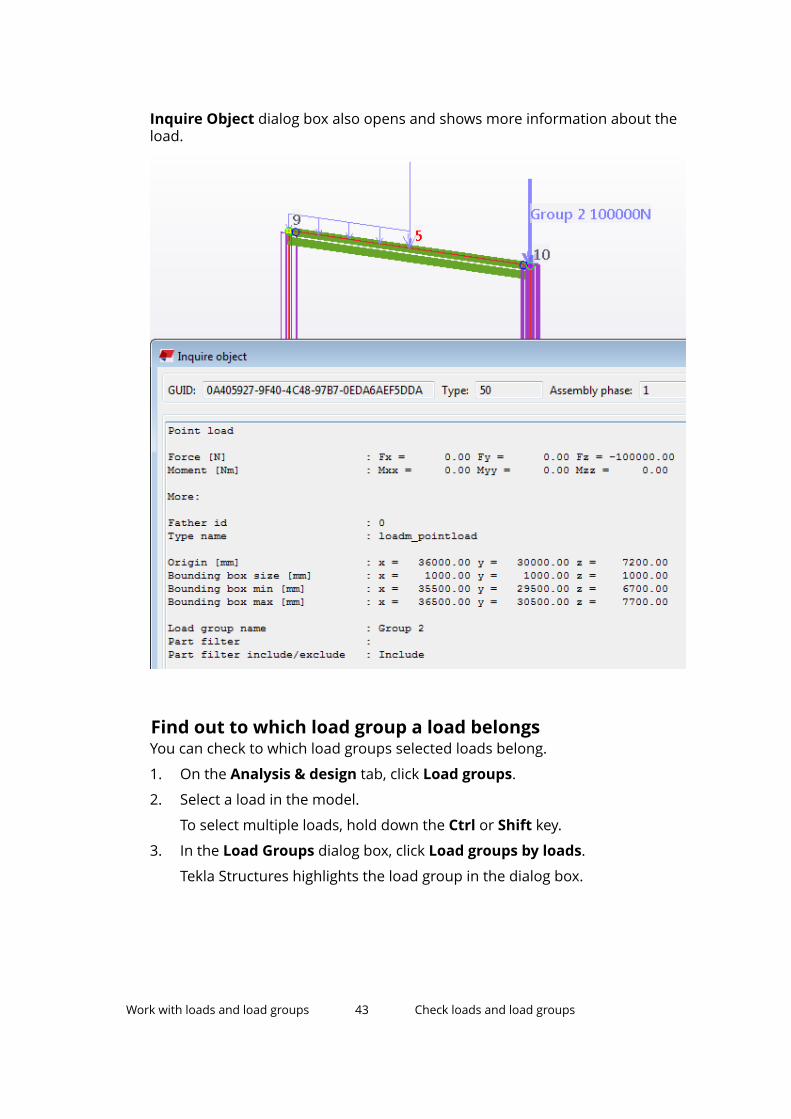
Inquire Object dialog box also opens and shows more information about theload.
Find out to which load group a load belongsYou can check to which load groups selected loads belong.
1. On the Analysis & design tab, click Load groups.
2. Select a load in the model.
To select multiple loads, hold down the Ctrl or Shift key.
3. In the Load Groups dialog box, click Load groups by loads.
Tekla Structures highlights the load group in the dialog box.
Work with loads and load groups 43 Check loads and load groups

Find out which loads belong to a load groupYou can check which loads belong to a selected load group.
1. On the Analysis & design tab, click Load groups.
2. In the Load Groups dialog box:
a. Select a load group from the list.
b. Click Loads by load groups.
Tekla Structures highlights the loads of the load group in the model.
Check loads using reportsYou can create reports of loads and load groups, and use them to check loadand load group information.
When you select a row that contains an ID number in a load report, TeklaStructures highlights and selects the corresponding load in the model.
Tekla Structures includes the following standard report templates for loadsand load groups:
• L_Loaded_Part• L_Loadgroups• L_Loadgroups_and_loads• L_Loads• L_Part_Loads
Example
This example report uses the L_Loadgroups_and_loads template:
Work with loads and load groups 44 Move loads to another load group

4.3 Move loads to another load groupYou can change the load group of a load, or move several loads at the sametime to another load group.
To move loads to another load group, do one of the following:
To Do thisChange the load group of aload
1. Double-click a load in the model.
2. In the load properties dialog box:
a. Select a new load group in the Load groupname list.
b. Click Modify.Move loads to another loadgroup
1. Select the loads in the model.
2. On the Analysis & design tab, click Loadgroups.
3. In the Load Groups dialog box:
a. Select a load group.
b. Click Change load group.
See also
Group loads together (page 18)
Work with loads and load groups (page 41)
4.4 Export load groupsYou can export load groups to a file and then use them in another TeklaStructures model.
Before you start, ensure that you have created the relevant load groups.
1. On the Analysis & design tab, click Load groups.
2. In the Load Groups dialog box:
a. Select the load group or groups to export.
To select multiple load groups, hold down the Ctrl or Shift key.
b. Click Export.
3. In the Export Load Groups dialog box:
a. Browse for the folder to which you want to save the load group file.
b. Enter a name for the file in the Selection box.
Work with loads and load groups 45 Export load groups

c. Click OK.
The file name extension of a load group file is .lgr.
See also
Import load groups (page 46)
Group loads together (page 18)
4.5 Import load groupsYou can import load groups from another Tekla Structures model if they havebeen exported to a file.
Before you start, ensure that you have the relevant load groups exported to afile.
1. On the Analysis & design tab, click Load groups.
2. In the Load Groups dialog box, click Import.
3. In the Import Load Groups dialog box:
a. Browse for the folder where the load group file is.
b. Select the load group file (.lgr) to import.
c. Click OK.
See also
Export load groups (page 45)
Group loads together (page 18)
Work with loads and load groups 46 Import load groups

5 Create analysis models
This section explains how to create analysis models in Tekla Structures.
Click the links below to find out more:
Define basic properties for an analysis model (page 47)
Objects included in analysis models (page 48)
Select the analysis application (page 50)
Create an analysis model (page 50)
5.1 Define basic properties for an analysis modelBefore you create an analysis model, first define the basic analysis modelproperties, such as analysis model name, creation method, and analysismethod.
1. On the Analysis & design tab, click A&D models.
2. In the Analysis & Design Models dialog box, click New.
3. In the Analysis Model Properties dialog box:
a. Enter a unique name for the analysis model.
For example, you can use a name that describes the portion of thephysical model you want to analyze.
b. Select the creation method for the analysis model.
Whichever method you choose, you can easily add and removeobjects later.
If you select By selected parts and loads or Floor model byselected parts and loads, select the parts and loads in the physicalmodel.
c. To make the analysis model more accurate, select a filter from theSecondary member filter list.
Create analysis models 47 Define basic properties for an analysis model
d. On the Analysis tab, change the analysis method if you need to run anon-linear analysis.
e. If needed, define other analysis model properties.
f. Click OK.
See also
Analysis model properties (page 110)
Objects included in analysis models (page 48)
Select the analysis application (page 50)
Create an analysis model (page 50)
5.2 Objects included in analysis modelsYou can define which objects to include in an analysis model. Tekla Structuresincludes or ignores some objects automatically.
The following factors affect which objects Tekla Structures includes in analysismodels:
• Which objects you select, add, remove, or ignore
• Analysis model creation method
• Analysis model filter
Tekla Structures ignores the following objects in the analysis, even if you haveincluded them in an analysis model:
• Parts and loads that are filtered out
• Component objects, such as minor parts, bolts, and reinforcing bars
• Parts whose analysis class is Ignore
• Parts whose analysis part has been deleted
The following components set the analysis properties of the parts they create,so these parts are included in analysis models:
• Shed (S57)
• Building (S58) and (S91)
• Slab generation (61) and (62)
• Truss (S78)
See also
Analysis model creation method (page 49)
Analysis model filter (page 49)
Create analysis models 48 Objects included in analysis models

Add objects to an analysis model (page 62)
Remove objects from an analysis model (page 62)
Delete an analysis part (page 82)
Analysis class options and colors (page 126)
Analysis model creation methodYou can define which objects to include in an analysis model by selecting thecreation method for the analysis model.
The available analysis model creation methods are:
Option DescriptionFull model Includes all main parts and loads, except for parts
whose analysis class is Ignore. Tekla Structuresautomatically adds physical objects to the analysismodel when they are created.
By selected parts andloads
Only includes selected parts and loads, and partscreated by components.
To later add or remove parts and loads, use thefollowing buttons in the Analysis & Design Modelsdialog box:
• Add selected parts
• Remove selected partsFloor model by selectedparts and loads
Only includes selected columns, slabs, floor beams,and loads. Tekla Structures replaces columns in thephysical model with supports.
See also
Analysis model filter (page 49)
Create an analysis model (page 50)
Add objects to an analysis model (page 62)
Remove objects from an analysis model (page 62)
Change the creation method of an analysis model (page 55)
Analysis model filterYou can use an analysis model filter to select parts to include in or excludefrom an analysis model.
Create analysis models 49 Objects included in analysis models

The analysis model filter works in a similar way to the selection filter, but TeklaStructures saves the settings with the analysis model properties. This meansthat you can check the criteria you used to select objects.
Tekla Structures automatically adds the new objects you create in the physicalmodel to the analysis model if they fulfill the criteria in the analysis modelfilter.
TIP Use the analysis model filter to filter out non-structural parts, such as railings,from the analysis model.
See also
Objects included in analysis models (page 48)
5.3 Select the analysis applicationYou can use various analysis applications with Tekla Structures. You can alsotransfer analysis data in several formats.
Before you start, ensure that you have the relevant analysis application, orapplications, and Tekla Structures installed on your computer. You also have toinstall a direct link between Tekla Structures and each analysis application. Ifyou do not have these installed, you will not be able to see and select anyanalysis application options.
To define which analysis application, or format, to use for an analysis model:
1. In Tekla Structures, go to the Analysis & design tab and click A&Dmodels.
2. In the Analysis & Design Models dialog box, do one of the following:
• To set the analysis application for a new analysis model, click New.
• To change the analysis application of an existing analysis model, selectthe analysis model, and then click Properties.
3. In the Analysis Model Properties dialog box:
a. Select the analysis application from the Analysis application list onthe Analysis model tab.
b. Click OK.
See also
About analysis applications (page 12)
Link Tekla Structures with an analysis application (page 12)
Create analysis models 50 Select the analysis application

5.4 Create an analysis modelThere are several methods to create an analysis model in Tekla Structures.
Click the links below to find out more:
Create an analysis model of entire physical and load models (page 51)
Create an analysis model for specific parts and loads (page 51)
Create a modal analysis model (page 52)
Copy an analysis model (page 66)
Create an analysis model of entire physical and loadmodelsYou can create an analysis model that includes all parts and loads you have ina physical model.
Before you start, create the parts and loads you want to include in the analysismodel.
1. On the Analysis & design tab, click A&D models.
2. In the Analysis & Design Models dialog box, click New.
3. In the Analysis Model Properties dialog box:
a. Define the basic analysis model properties.
b. In the Creation method list on the Analysis model tab, select Fullmodel.
c. If needed, enter or modify the remaining analysis model properties.
d. Click OK.
Tekla Structures automatically adds physical objects to the Full model analysismodels when the objects are created.
See also
Define basic properties for an analysis model (page 47)
Analysis model properties (page 110)
Modify analysis models (page 54)
Change the creation method of an analysis model (page 55)
Create analysis models 51 Create an analysis model

Create an analysis model for specific parts and loadsYou can create an analysis model that includes the selected parts and loads.
Before you start, create the parts and loads you want to include in the analysismodel.
1. Select the objects you want to include in the analysis model.
2. On the Analysis & design tab, click A&D models.
3. In the Analysis & Design Models dialog box, click New.
4. In the Analysis Model Properties dialog box:
a. Define the basic analysis model properties.
b. In the Creation method list on the Analysis model tab, select Byselected parts and loads or Floor model by selected parts andloads.
c. If needed, enter or modify the remaining analysis model properties.
d. Click OK.
Limitations
If you create an analysis model for selected objects and then use a filter toleave out more objects, you cannot revert to the original objects, even if youremove the filtering.
See also
Define basic properties for an analysis model (page 47)
Analysis model creation method (page 49)
Analysis model properties (page 110)
Add objects to an analysis model (page 62)
Remove objects from an analysis model (page 62)
Change the creation method of an analysis model (page 55)
Create a modal analysis modelYou can create modal analysis models of Tekla Structures models. In modalanalysis models, resonant frequency and the associated pattern of structuraldeformation called mode shapes are determined, instead of performing stressanalysis.
Before you start, create the parts you want to include in the analysis model.
1. If you want to create an analysis model for specific parts, select them inthe model.
2. On the Analysis & design tab, click A&D models.
Create analysis models 52 Create an analysis model

3. In the Analysis & Design Models dialog box, click New.
4. In the Analysis Model Properties dialog box:
a. Define the basic analysis model properties.
b. On the Analysis tab, select Yes in the Modal analysis model list.
c. Click OK.
See also
Define modal masses for an analysis model (page 58)
Define basic properties for an analysis model (page 47)
Analysis model properties (page 110)
Create analysis models 53 Create an analysis model

6 Modify analysis models
This section explains how to modify analysis models and how to work withanalysis model objects.
Click the links below to find out more:
Check which objects are included in an analysis model (page 54)
Modify the properties of an analysis model (page 55)
Add objects to an analysis model (page 62)
Remove objects from an analysis model (page 62)
Create an analysis node (page 63)
Create a rigid link (page 64)
Merge analysis nodes (page 65)
Copy an analysis model (page 66)
Delete an analysis model (page 67)
6.1 Check which objects are included in an analysismodelYou can check which parts and loads are included in an analysis model.
1. On the Analysis & design tab, click A&D models.
2. In the Analysis & Design Models dialog box:
a. Select an analysis model.
b. Click Select objects.
Tekla Structures highlights and selects the parts and loads in thephysical model.
To remove the highlighting, click the view background.
Modify analysis models 54 Check which objects are included in an analysismodel

See also
Objects included in analysis models (page 48)
Add objects to an analysis model (page 62)
Remove objects from an analysis model (page 62)
6.2 Modify the properties of an analysis model1. On the Analysis & design tab, click A&D models.
2. In the Analysis & Design Models dialog box:
a. Select the analysis model to modify.
b. Click Properties.
3. In the Analysis Model Properties dialog box:
a. Modify the properties.
b. If you change the secondary member filter, select the Reapply to allparts check box to apply the change to all parts in the analysis model.
If you do not select the Reapply to all parts check box, TeklaStructures will use the new filter only for the new parts in the analysismodel.
c. Click OK to save the changes.
See also
Change the creation method of an analysis model (page 55)
Define the axis settings of an analysis model (page 56)
Define seismic loads for an analysis model (page 57)
Define modal masses for an analysis model (page 58)
Define the design properties of an analysis model (page 59)
Define analysis model rules (page 59)
Analysis model properties (page 110)
Modify analysis models 55 Modify the properties of an analysis model

Change the creation method of an analysis modelYou can change the creation method of existing analysis models.
If you change the creation method of an analysis model to Full model, TeklaStructures automatically adds all parts and loads in the physical model to theanalysis model.
1. On the Analysis & design tab, click A&D models.
2. In the Analysis & Design Models dialog box:
a. Select the analysis model to modify.
b. Click Properties.
3. In the Analysis Model Properties dialog box:
a. On the Analysis model tab, select the required option from theCreation method list.
b. Click OK to save the analysis model properties.
Example
To change the analysis model creation method from Full model to Selectedparts and loads:
1. Copy an analysis model that has been created using the Full modelcreation method.
2. Change the creation method of the copied analysis model to By selectedparts and loads.
3. Remove the unwanted parts and loads from the analysis model.
See also
Analysis model creation method (page 49)
Copy an analysis model (page 66)
Remove objects from an analysis model (page 62)
Add objects to an analysis model (page 62)
Define the axis settings of an analysis modelYou can define and modify the analysis axis settings of an entire analysismodel so that the settings apply to all parts in the analysis model.
1. On the Analysis & design tab, click A&D models.
2. In the Analysis & Design Models dialog box, do one of the following:
• To define the axis settings for a new analysis model, click New.
• To modify the axis settings of an existing analysis model, select theanalysis model, and then click Properties.
Modify analysis models 56 Modify the properties of an analysis model

3. In the Analysis Model Properties dialog box:
a. Click More settings on the Analysis model tab.
b. In the Member axis location list, select an option.
If you select Model default, Tekla Structures uses the axis propertiesof individual analysis parts.
c. Click OK.
See also
Define or modify the axis location of an analysis part (page 79)
Define the location of analysis parts (page 78)
Define seismic loads for an analysis modelYou can define additional lateral seismic loads for analysis models. The seismicloads are created in the x and y directions according to several building codesusing a static equivalent approach.
Before you start, ensure that you have the appropriate load modeling codeselected in File menu --> Settings --> Options --> Load modeling --> Currentcode.
1. On the Analysis & design tab, click A&D models.
2. In the Analysis & Design Models dialog box, do one of the following:
• To create a new seismic analysis model, click New.
• To modify an existing analysis model, select the analysis model, andthen click Properties.
The Analysis Model Properties dialog box opens.
3. On the Seismic tab:
a. In the Type list, select the building code to be used in the seismicanalysis to generate seismic loads.
b. Define the seismic properties.
4. On the Seismic masses tab, define the loads and load groups to beincluded in the seismic analysis:
a. To include the self-weight of parts, select the Include self weight asseismic mass check box.
b. If needed, click Copy modal analysis masses to include the sameload groups in the seismic analysis as in the modal analysis.
c. To move the appropriate load groups to the Included load groupstable, select them and use the arrow buttons.
Modify analysis models 57 Modify the properties of an analysis model

d. For each load group in the Included load groups table, enter a loadfactor.
5. Click OK.
See also
Analysis model properties (page 110)
Define modal masses for an analysis modelYou can perform a modal analysis instead of a stress analysis. In the modalanalysis, resonant frequencies and the associated patterns of structuraldeformation called mode shapes are determined. For the modal analysis, youcan define modal masses to be used instead of static load combinations.
1. On the Analysis & design tab, click A&D models.
2. In the Analysis & Design Models dialog box, do one of the following:
• To create a new modal analysis model, click New.
• To modify an existing analysis model, select the analysis model, andthen click Properties.
The Analysis Model Properties dialog box opens.
3. On the Analysis tab, select Yes from the Modal analysis model list.
This forces Tekla Structures to ignore static load combinations.
4. On the Modal analysis tab, define the modal analysis properties and theload groups to be included as masses in the modal analysis:
a. Enter the count of modes to calculate.
b. Enter the maximum frequency to calculate.
c. Select the appropriate Include self weight check boxes to indicatethe directions for which Tekla Structures includes the self-weight ofparts in the modal analysis.
d. If suitable, click Copy seismic masses to include the same loadgroups in the modal analysis as in the seismic analysis.
e. To move the appropriate load groups to the Included load groupstable, select them and use the arrow buttons.
f. For each load group in the Included load groups table, enter a loadfactor and set the mass direction.
In the Mass direction column, select either:
• XYZ to include the load in all three directions.
• Model default to include the load only in the direction of the load.
5. Click OK.
Modify analysis models 58 Modify the properties of an analysis model
See also
Create a modal analysis model (page 52)
Analysis model properties (page 110)
Define the design properties of an analysis modelYou can define and modify the design properties of an entire analysis modelso that the properties apply to all parts in the analysis model.
1. On the Analysis & design tab, click A&D models.
2. In the Analysis & Design Models dialog box, do one of the following:
• To define the design properties for a new analysis model, click New.
• To modify the design properties of an existing analysis model, selectthe analysis model, and then click Properties.
3. In the Analysis Model Properties dialog box:
a. Go to a Design tab.
There are separate Design tabs for steel, concrete, and timber.
b. Select the design code and design method for the material.
c. If needed, modify the design properties.
Click an entry in the Value column, and then enter a value or selectan option.
d. Click OK.
See also
Define design properties for analysis parts (page 74)
Analysis model properties (page 110)
Define analysis model rulesYou can create analysis model rules to define how Tekla Structures handlesindividual parts when it creates analysis models, and how parts are connectedwith each other.
Open the Analysis Model Rules dialog boxUse the Analysis Model Rules dialog box to work with the rules of an analysismodel.
1. On the Analysis & design tab, click A&D models.
2. In the Analysis & Design Models dialog box:
Modify analysis models 59 Modify the properties of an analysis model

a. Select an analysis model.
b. Click Properties.
3. In the Analysis Model Properties dialog box:
a. Click More settings on the Analysis model tab.
b. Click Analysis model rules.
The Analysis Model Rules dialog box opens.
Add an analysis model rule1. Open the Analysis Model Rules dialog box.
2. Click Add to define how two groups of parts are connected with eachother in the analysis.
3. In the Selection filter 1 column, select a filter to define the first partgroup.
If you need to create a new selection filter that suits your needs, clickSelection filter.
4. In the Selection filter 2 column, select a filter to define the second partgroup.
5. If you want to prevent connections between the part groups, selectDisabled in the Status column.
6. In the Linkage column, select one of the following options:
• (blank): Merges nodes or creates a rigid link.
• Merge: Always merges nodes when parts matching the first selectionfilter connect with parts matching the second selection filter.
• Rigid link: Creates a rigid link when parts matching the first selectionfilter connect with parts matching the second selection filter.
• Rigid link, moment release at node 1: Creates a rigid link and amoment release at the nodes of parts matching the first selectionfilter.
• Rigid link, moment release at node 2: Creates a rigid link and amoment release at the nodes of parts matching the second selectionfilter.
• Rigid link, moment release at both nodes: Creates a rigid link andmoment releases at the nodes of parts matching the first and thesecond selection filter.
7. Click OK to save the rules.
8. In the Analysis Model Properties dialog box, click OK to save the rules asproperties of the current analysis model.
Modify analysis models 60 Modify the properties of an analysis model

Organize analysis model rulesYou can change the order of the analysis model rules that you have created foran analysis model. The last rule in the Analysis Model Rules dialog boxoverrides the previous ones.
1. Open the Analysis Model Rules dialog box.
2. Select a rule.
3. To move the rule up in the list, click Move up.
To move the rule down in the list, click Move down.
4. Click OK to save the changes.
5. In the Analysis Model Properties dialog box, click OK to save the rules asproperties of the current analysis model.
Delete analysis model rulesYou can delete one or more selected analysis model rules from an analysismodel.
1. Open the Analysis Model Rules dialog box.
2. Select the rule or rules to delete.
To select multiple rules, hold down the Ctrl or Shift key.
3. Click Remove.
4. Click OK to save the changes.
5. In the Analysis Model Properties dialog box, click OK.
Test analysis model rulesYou can test the analysis model rules that you have created on the selectedparts before you bring the rules into use.
1. In the model, select the parts on which you want to test the rules.
2. In the Analysis Model Rules dialog box:
a. Click Test selected parts.
Tekla Structures opens the Analysis model rules test report that liststhe IDs of the selected parts, matching selection filters, and theresults of using the rules.
b. If needed, modify or reorganize the rules and test again.
c. When the rules work as you desired, click OK to save the rules.
3. In the Analysis Model Properties dialog box, click OK to save the rules asproperties of the current analysis model.
Modify analysis models 61 Modify the properties of an analysis model
Save analysis model rulesYou can save analysis model rules for later use in the same or another analysismodel.
1. In the Analysis Model Rules dialog box:
a. If needed, save the rules for later use:
Enter a unique name in the box next to the Save as button, and thenclick Save as.
Tekla Structures saves the rules file in the \attributes folder underthe current model folder.
The file name extension of an analysis model rules file is .adrules.
b. Click OK.
2. In the Analysis Model Properties dialog box, click OK to save the rules asproperties of the current analysis model.
6.3 Add objects to an analysis modelYou can modify existing analysis models by adding parts and loads to them.
1. In the physical model, select the parts and loads to add.
2. On the Analysis & design tab, click A&D models.
3. In the Analysis & Design Models dialog box:
a. Select the analysis model to modify.
b. Click Add selected.
Tekla Structures adds the selected objects to the selected analysismodel.
See also
Check which objects are included in an analysis model (page 54)
Remove objects from an analysis model (page 62)
Copy an analysis part (page 81)
Create an analysis node (page 63)
Create a rigid link (page 64)
6.4 Remove objects from an analysis modelYou can modify existing analysis models by removing parts and loads fromthem.
Modify analysis models 62 Add objects to an analysis model

1. In the physical model, select the parts and loads to remove.
2. On the Analysis & design tab, click A&D models.
3. In the Analysis & Design Models dialog box:
a. Select the analysis model to modify.
b. Click Remove selected.
Tekla Structures removes the selected objects from the selectedanalysis model.
See also
Check which objects are included in an analysis model (page 54)
Add objects to an analysis model (page 62)
Delete an analysis part (page 82)
6.5 Create an analysis nodeYou can create nodes on analysis parts. The analysis nodes you manually addare not moved with the analysis part if you move the analysis part.
1. On the Analysis & design tab, click A&D models.
2. In the Analysis & Design Models dialog box, select the analysis model towhich you want to add the node.
3. On the Analysis & design tab, click Node .
4. Pick the location where you want to add the node.
See also
Analysis model objects (page 9)
Analysis node properties (page 130)
Analysis node colors (page 63)
Merge analysis nodes (page 65)
Analysis node colorsAnalysis nodes can have different colors in analysis models.
Modify analysis models 63 Create an analysis node
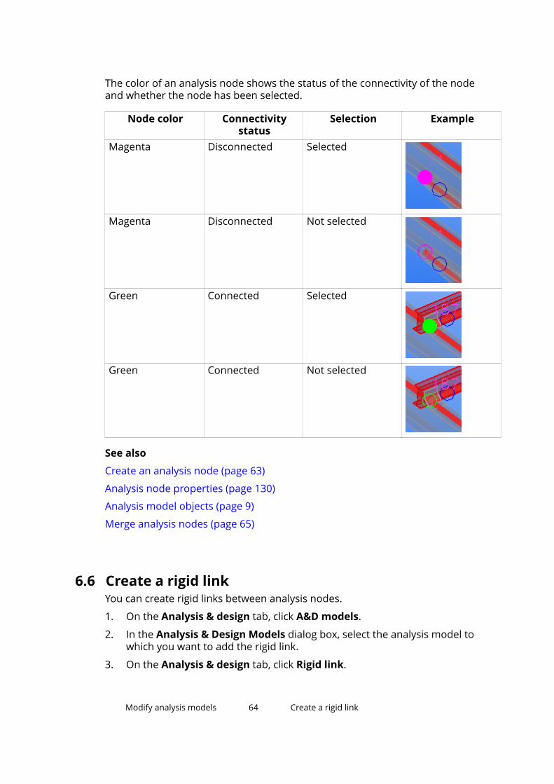
The color of an analysis node shows the status of the connectivity of the nodeand whether the node has been selected.
Node color Connectivitystatus
Selection Example
Magenta Disconnected Selected
Magenta Disconnected Not selected
Green Connected Selected
Green Connected Not selected
See also
Create an analysis node (page 63)
Analysis node properties (page 130)
Analysis model objects (page 9)
Merge analysis nodes (page 65)
6.6 Create a rigid linkYou can create rigid links between analysis nodes.
1. On the Analysis & design tab, click A&D models.
2. In the Analysis & Design Models dialog box, select the analysis model towhich you want to add the rigid link.
3. On the Analysis & design tab, click Rigid link.
Modify analysis models 64 Create a rigid link

4. Pick the start point for the rigid link.
5. Pick the end point for the rigid link.
See also
Analysis model objects (page 9)
Analysis rigid link properties (page 132)
Create an analysis node (page 63)
6.7 Merge analysis nodesYou can merge analysis nodes that are located close to each other into a singlenode.
1. On the Analysis & design tab, click A&D models.
2. In the Analysis & Design Models dialog box, select the analysis model inwhich you want to merge nodes.
3. Select the nodes you want to merge.
4. On the Analysis & design tab, click Merge nodes.
Modify analysis models 65 Merge analysis nodes

5. If you are merging nodes on analysis parts that have Keep axis positionset to Yes, Tekla Structures prompts you to change it to No. To accept thechange, click Set keep axis as No.
6. Pick the location to which you want the nodes to be merged.
Tekla Structures merges the nodes into a single node and extends theanalysis parts accordingly.
See also
Create an analysis node (page 63)
Analysis node properties (page 130)
Analysis node colors (page 63)
6.8 Copy an analysis modelYou can create copies of existing analysis models. You can then use the copies,for example, to create multiple calculations with different settings.
1. On the Analysis & design tab, click A&D models.
2. In the Analysis & Design Models dialog box:
a. Select the analysis model to copy.
b. Click Copy.
Tekla Structures adds the new analysis model to the list with thename <original model name> - Copy.
See also
Modify analysis models (page 54)
Modify analysis models 66 Copy an analysis model

Modify analysis parts (page 68)
6.9 Delete an analysis modelYou can delete unnecessary analysis models.
1. On the Analysis & design tab, click A&D models.
2. In the Analysis & Design Model dialog box:
a. Select an analysis model.
b. Click Delete.
3. Click Yes to confirm.
See also
Modify analysis models (page 54)
Create analysis models (page 47)
Modify analysis models 67 Delete an analysis model

7 Modify analysis parts
This section explains how to modify analysis parts and their properties.
Click the links below to find out more:
About analysis part properties (page 68)
Modify the properties of an analysis part (page 69)
Define support conditions (page 71)
Define design properties for analysis parts (page 74)
Define the location of analysis parts (page 78)
Copy an analysis part (page 81)
Delete an analysis part (page 82)
7.1 About analysis part propertiesYou can view, define, or modify analysis part properties before or aftercreating analysis models. You can define analysis part propertiesindependently from analysis models, or modify them according to an analysismodel. Analysis parts can have different properties in different analysismodels.
You can define analysis properties for parts before you create analysis models.Tekla Structures applies the analysis part properties when the parts are addedto an analysis model. You can also modify analysis part properties after youhave created analysis models.
If you view the analysis properties of a part before you have modified theproperties or created any analysis models, Tekla Structures displays theanalysis properties according to the part type. For example, all steel beamsfirst have identical analysis properties. These settings are called currentanalysis properties.
If you modify the analysis properties of a part before you create analysismodels, Tekla Structures saves the modified settings as the default analysis
Modify analysis parts 68 About analysis part properties
properties of the part in the AnalysisPartDefaults.db6 file under thecurrent model folder. These default analysis properties override the currentanalysis properties and will be used when you add the part to an analysismodel.
When you create analysis models and then view the analysis properties of apart, Tekla Structures displays the properties according to the selected analysismodel. If you do not have an analysis model selected in the Analysis & DesignModels dialog box, Tekla Structures displays the current analysis propertiesfor unchanged parts and the default analysis properties for modified parts.
See also
Modify the properties of an analysis part (page 69)
7.2 Modify the properties of an analysis partYou can view, define, and modify the properties of analysis parts using theanalysis part properties dialog box.
To access the properties of an analysis part, do one of the following:
To Do thisDefine or modify thecurrent analysisproperties of a part typeindependently fromanalysis models
1. On the Analysis & design tab, click Part analysisproperties, and then click a relevant part type.
2. In the analysis properties dialog box:
a. Modify the properties.
b. Click Apply or OK to save the changes as thecurrent analysis properties of the part type.
Tekla Structures will use these current analysisproperties for new parts of this type that you create inthe model.
Define or modify thedefault analysisproperties of a partindependently fromanalysis models
1. Ensure that you do not have an analysis modelselected in the Analysis & Design Models dialogbox.
2. In the physical model, select a part.
3. Right-click and select Analysis Properties.
4. In the part’s analysis properties dialog box:
a. Modify the properties.
Modify analysis parts 69 Modify the properties of an analysis part
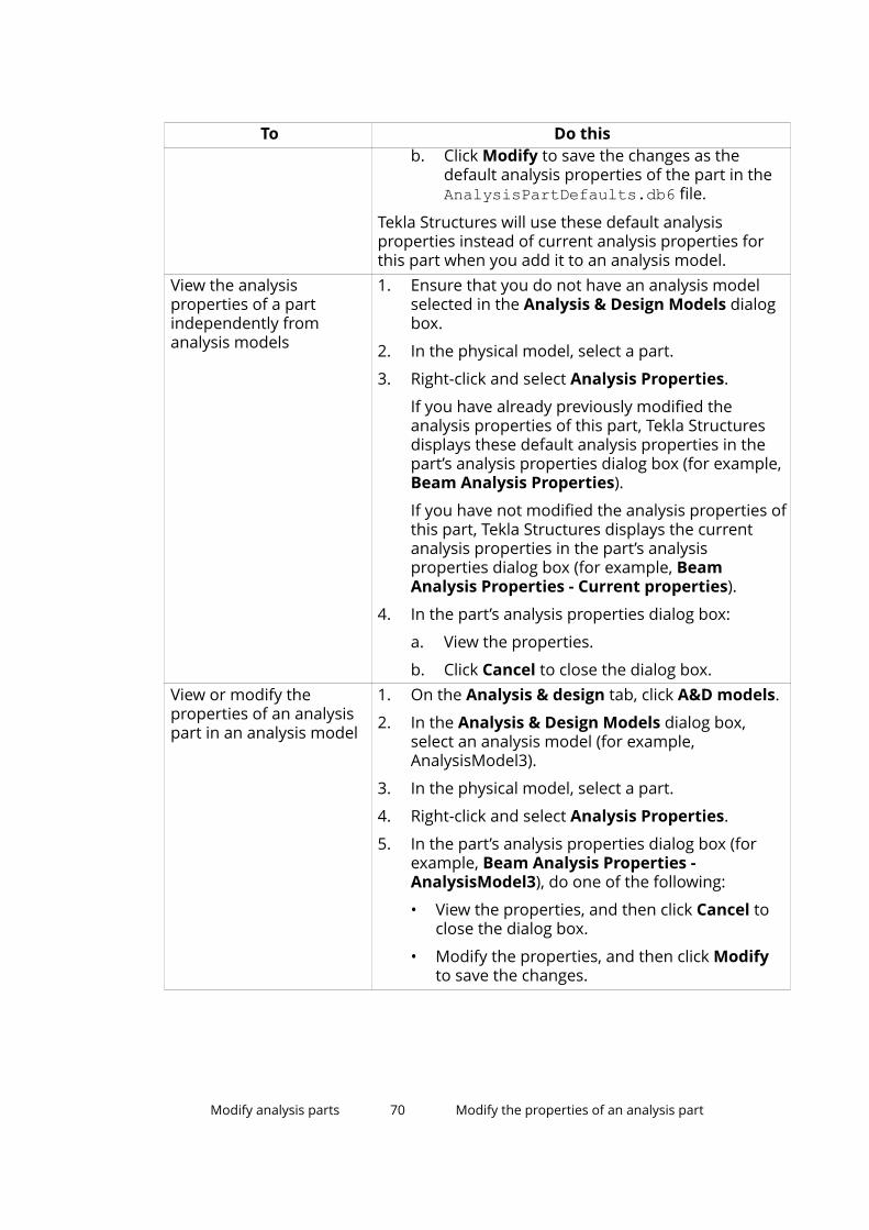
To Do thisb. Click Modify to save the changes as the
default analysis properties of the part in theAnalysisPartDefaults.db6 file.
Tekla Structures will use these default analysisproperties instead of current analysis properties forthis part when you add it to an analysis model.
View the analysisproperties of a partindependently fromanalysis models
1. Ensure that you do not have an analysis modelselected in the Analysis & Design Models dialogbox.
2. In the physical model, select a part.
3. Right-click and select Analysis Properties.
If you have already previously modified theanalysis properties of this part, Tekla Structuresdisplays these default analysis properties in thepart’s analysis properties dialog box (for example,Beam Analysis Properties).
If you have not modified the analysis properties ofthis part, Tekla Structures displays the currentanalysis properties in the part’s analysisproperties dialog box (for example, BeamAnalysis Properties - Current properties).
4. In the part’s analysis properties dialog box:
a. View the properties.
b. Click Cancel to close the dialog box.View or modify theproperties of an analysispart in an analysis model
1. On the Analysis & design tab, click A&D models.
2. In the Analysis & Design Models dialog box,select an analysis model (for example,AnalysisModel3).
3. In the physical model, select a part.
4. Right-click and select Analysis Properties.
5. In the part’s analysis properties dialog box (forexample, Beam Analysis Properties -AnalysisModel3), do one of the following:
• View the properties, and then click Cancel toclose the dialog box.
• Modify the properties, and then click Modifyto save the changes.
Modify analysis parts 70 Modify the properties of an analysis part

See also
Analysis part properties (page 116)
About analysis part properties (page 68)
Modify analysis parts (page 68)
7.3 Define support conditionsIn structural analysis, the stresses and deflections of a part depend on how itis supported by, or connected to, other parts. You normally use restraints orsprings to model connections. These determine how analysis parts move,deflect, warp, and deform in relation to each other, or to nodes.
Part ends and nodes have degrees of freedom (DOF) in three directions. Thedisplacement of a part end can be free or fixed, and the rotation can bepinned or fixed. If the degree of connectivity is between free, or pinned, andfixed, use springs with different elastic constants to model them.
Tekla Structures uses analysis part, connection, or detail properties todetermine how to connect parts in the analysis model.
The analysis part properties determine the degrees of freedom for each end ofa part. The first end of a part has a yellow handle, the second end has amagenta handle.
See also
Define the support conditions of a part end (page 71)
Define the support conditions of a plate (page 72)
Support condition symbols (page 73)
Define the support conditions of a part endBefore you start, in the Analysis & Design Models dialog box, select theanalysis model in which you want to define the support conditions.
1. Select a part.
2. Right-click and select Analysis Properties.
3. In the part’s analysis properties dialog box:
• To define the support conditions for the start of the part (yellowhandle), go to the Start releases tab.
• To define the support conditions for the end of the part (magentahandle), go to the End releases tab.
4. In the Start or End list, select an option.
Modify analysis parts 71 Define support conditions

5. If needed for a supported part end, define the rotation.
6. If needed, modify the translational and rotational degrees of freedom.
7. If you selected Spring for any of the degrees of freedom, enter the springconstant.
The units depend on the settings in File menu --> Settings --> Options -->Units and decimals.
8. If you selected Partial release for any of the rotational degrees offreedom, specify the degree of connectivity.
Enter a value between 0 (fixed) and 1 (pinned).
9. Click Modify.
See also
Define the support conditions of a plate (page 72)
Support condition symbols (page 73)
Analysis part properties (page 116)
About analysis part properties (page 68)
Define the support conditions of a plateYou can define support conditions for contour plates, concrete slabs, andconcrete panels. Tekla Structures creates supports for the bottom edge of apanel, for all edge nodes of a slab or a plate, or for all nodes of a beam. Forpanels, the bottom edge can be inclined.
Before you start, in the Analysis & Design Models dialog box, select theanalysis model in which you want to define the support conditions.
1. Select a plate.
2. Right-click and select Analysis Properties.
3. In the plate’s analysis properties dialog box:
a. On the Area attributes tab, select an option in the Supported list:
• No: No supports are created.
• Simply (translations): Only translations are fixed.
• Fully: Both translations and rotations are fixed.
b. Click Modify.
See also
Define the support conditions of a part end (page 71)
Support condition symbols (page 73)
Modify analysis parts 72 Define support conditions

Analysis part properties (page 116)
About analysis part properties (page 68)
Support condition symbolsTekla Structures displays symbols for nodes that indicate the supportconditions of a node.
Symbol Support conditionNo supports
Pinned connection
Fixed connection
Translational direction fixed
Modify analysis parts 73 Define support conditions

Symbol Support conditionTranslational direction spring
Rotational fixed
Rotational spring
If you do not want to show the support condition symbols in model views, setthe advanced option XS_AD_SUPPORT_VISUALIZATION to FALSE in File menu--> Settings --> Advanced Options --> Analysis & Design .
See also
Define support conditions (page 71)
7.4 Define design properties for analysis partsYou can define design properties for individual analysis parts. Designproperties are properties which can vary according to the design code and thematerial of the part (for example, design settings, factors, and limits).
Modify analysis parts 74 Define design properties for analysis parts

The properties you see when you first open the Design tab in an analysis partproperties dialog box are the properties that apply to the entire analysis modelyou have selected in the Analysis & Design Models dialog box.
You can modify the design properties of specific analysis parts using theappropriate analysis part properties dialog boxes. When you change a value orselect an option in the Value column, the check box in the Use defaultcolumn is cleared indicating that the analysis model properties are not in usefor this particular analysis part and design property.
Example
If an analysis model contains parts with different material grades, define themost common material grade using the analysis model properties. Thenchange the material grade of specific parts in the analysis part properties.
See also
Omit analysis parts from design (page 75)
Define the buckling lengths of a column (page 76)
Define the design properties of an analysis model (page 59)
Analysis part properties (page 116)
Modify analysis parts 75 Define design properties for analysis parts

Omit analysis parts from designYou can omit individual analysis parts from the design check during theanalysis.
Before you start, in the Analysis & Design Models dialog box, select theanalysis model in which you want to modify the analysis part properties.
1. In the physical model, select a part.
2. Right-click and select Analysis Properties.
3. In the part’s analysis properties dialog box:
a. Go to the Design tab.
b. In the Value column, select No for Check design - Enable designcheck of member.
c. Click Modify.
See also
Define design properties for analysis parts (page 74)
About analysis part properties (page 68)
Define the buckling lengths of a columnYou can define buckling lengths for columns and column segments. Columnsegments represent the building levels. Tekla Structures automatically dividescolumns into segments at the point where a support in the buckling directionexists, or where the column profile changes.
Effective buckling length is K*L, where K is the length factor and L is thebuckling length.
A column can have different buckling lengths in different analysis models.
Before you start, in the Analysis & Design Models dialog box, select theanalysis model in which you want to define the buckling lengths.
1. Select a column.
2. Right-click and select Analysis Properties.
3. In the column’s analysis properties dialog box:
a. Go to the Design tab and the Value column.
b. Select an option for Kmode.
c. Enter one or more values for K - Length factor for buckling in the yand/or z direction.
Modify analysis parts 76 Define design properties for analysis parts

The number of values you can enter depends on the option youselected for Kmode.
To enter multiple values, enter a value for each column segmentstarting from the lowest segment, and use spaces to separate thevalues. You can also use multiplication to repeat factors, for example,3*2.00.
d. Enter one or more values for L - Buckling length in the y and/or zdirection.
• To automatically calculate length values, leave the fields blank.
• To override one or more length values, enter values in the relevantbuckling length fields. The number of values you need to enterdepends on the option you selected for Kmode. You can usemultiplication to repeat buckling lengths, for example, 3*4000.
e. Click Modify.
See also
Kmode options (page 77)
About analysis part properties (page 68)
Kmode optionsUse the Kmode options to define how Tekla Structures calculates the bucklinglengths of columns.
The options are:
Option DescriptionPhysical member L is the length of the column.Column segment L is the length of one column segment.Column segment,multiple values
L is the length of one column segment with user-defined factors and lengths for each column segment.
Analytical member L is the length of the member in the analysis model.Analytical member,multiple values
L is the length of the member in the analysis modelwith user-defined factors and lengths for eachmember.
Modify analysis parts 77 Define design properties for analysis parts

See also
Define the buckling lengths of a column (page 76)
7.5 Define the location of analysis partsYou can define and modify the analysis axis location of individual parts in ananalysis model, or you can use the axis settings of the analysis model thatapply to all parts in the analysis model.
You can also define offsets for analysis parts and use handles to move analysisparts.
If you move an analysis part handle, you can view the offsets in the followingdialog boxes:
• Analysis Bar Position Properties
• Analysis Area Position Properties
Modify analysis parts 78 Define the location of analysis parts

• Analysis Area Edge Properties
If you move a physical part or an analysis part, these handle offsets will bereset. The Reset editing of selected parts command also resets the changesyou have made using the analysis part handles.
See also
Define or modify the axis location of an analysis part (page 79)
Define offsets for an analysis part (page 80)
Reset the editing of analysis parts (page 80)
Analysis bar position properties (page 134)
Analysis area position properties (page 134)
Analysis area edge properties (page 135)
Analysis part properties (page 116)
Define the axis settings of an analysis model (page 56)
Define or modify the axis location of an analysis partYou can define and modify the analysis axis location of individual parts. Theanalysis axis defines the location of an analysis part in relation to thecorresponding physical part. For example, the analysis part can be located onthe neutral axis or the reference line of the physical part.
Before you start:
• In the Analysis & Design Models dialog box, select the analysis model inwhich you want to modify the analysis part properties.
• For the selected analysis model, ensure that Member axis location isModel default in the Analysis Model Properties dialog box.
1. In the physical model, select a part.
2. Right-click and select Analysis Properties.
3. In the part’s analysis properties dialog box:
a. Go to the Position tab.
b. In the Axis list, select an option.
c. In the Keep axis position list, define whether the part’s analysis axiscan move, and in which direction when the part is connected withother parts.
d. If needed, use the Axis modifier boxes to define whether the axis isbound to global coordinates, to the nearest grid line, or neither.
e. Click Modify.
Modify analysis parts 79 Define the location of analysis parts

See also
Define offsets for an analysis part (page 80)
Analysis part properties (page 116)
About analysis part properties (page 68)
Define the axis settings of an analysis model (page 56)
Define offsets for an analysis partYou can define offsets for an analysis part. Offsets move the analysis part inrelation to the default location of the analysis axis.
Before you start, in the Analysis & Design Models dialog box, select theanalysis model in which you want to define offsets.
1. In the physical model, select a part.
2. Right-click and select Analysis Properties.
3. In the part’s analysis properties dialog box:
a. Go to the Position tab.
b. In the Offset boxes, define the offset of the analysis part from thephysical part’s analysis axis in the global x, y, and z directions.
These values change if you move the analysis part in the model.
These values do not reset if you move the physical part.
c. In the Longitudinal offset mode list, select whether the longitudinalend offsets Dx of the physical part are taken into account.
End offsets determine where Tekla Structures creates the end nodesof the analysis part.
d. Click Modify.
See also
Define or modify the axis location of an analysis part (page 79)
Analysis part properties (page 116)
Reset the editing of analysis partsIf you have changed the location of analysis parts using handles, you can resetthe selected analysis parts to the default analysis settings.
1. On the Analysis & design tab, click A&D models.
2. In the Analysis & Design Models dialog box, select the analysis model inwhich you want to reset parts.
Modify analysis parts 80 Define the location of analysis parts

3. Select the parts to reset.
4. On the Analysis & design tab, click Reset editing of selected parts.
See also
Define the location of analysis parts (page 78)
Modify analysis parts (page 68)
7.6 Copy an analysis partYou can create copies of existing analysis parts together with the appliedproperties and node offsets.
For example, you can use copying to apply analysis settings to multiplerepeated frames. First apply the correct analysis settings to one frame. Thencopy the settings to other similar frames.
1. On the Analysis & design tab, click A&D models.
2. In the Analysis & Design Models dialog box, select the analysis modelthat includes the part you want to copy and uses the analysis partproperties you want to use.
3. In the physical model, select the part to copy.
4. Do one of the following:
• On the Edit tab, click Copy.
• Right-click and select Copy.
5. Pick the origin for the copying.
6. Pick one or more destination points.
If there is an identical physical part at a destination point, Tekla Structurescreates an analysis part with settings identical to the original.
If there already was an analysis part at a destination point, TeklaStructures modifies the analysis part.
If a physical part at the destination point is not yet included in the analysismodel, Tekla Structures adds the part to the analysis model.
7. To stop copying, do one of the following:
• Press Esc.
• Right-click and select Interrupt.
See also
Modify analysis parts (page 68)
Modify analysis parts 81 Copy an analysis part

7.7 Delete an analysis partYou can remove parts from analysis models by deleting analysis parts.
If the analysis model creation method is Full model and you delete an analysispart, Tekla Structures ignores the part in the analysis. If the analysis modelcreation method is By selected parts and loads or Floor model by selectedparts and loads, and you delete an analysis part, Tekla Structures removesthe part from the analysis model.
1. On the Analysis & design tab, click A&D models.
2. In the Analysis & Design Models dialog box, select the analysis modelthat includes the part you want to delete.
3. Select the analysis part to delete.
4. Do one of the following:
• Right-click and select Delete.
• Press Delete.
TIP To undo the Delete command:
• For Full model analysis models, change the analysis class of the deleted partfrom Ignore to the original setting.
• For other analysis models, add the deleted part again to the analysis model.
See also
Remove objects from an analysis model (page 62)
Modify analysis models (page 54)
Analysis model creation method (page 49)
Modify analysis parts 82 Delete an analysis part

8 Combine loads
This section explains the load combination process in Tekla Structures.
Load combination is a process in which some simultaneously acting loadgroups are multiplied by their partial safety factors and combined with eachother according to specific rules.
Load combination rules are specific to a design process and are defined inbuilding or design codes. One of the most typical design processes is the limitstate design.
Load combination properties define how Tekla Structures combines loads. Thefollowing properties control the load combination process:
• Load modeling code (page 107)
• Load combination factors (page 107)
• Load combination types (page 108)
• Load group compatibility (page 20)
See also
About load combinations (page 83)
Create load combinations automatically (page 84)
Create a load combination (page 85)
Modify a load combination (page 86)
Copy load combinations between analysis models (page 87)
Delete load combinations (page 88)
8.1 About load combinationsA load combination is a set of load groups that is created in the loadcombination process. Each load combination represents a real loadingsituation, which means that permanent load should always be included ineach load combination.
Combine loads 83 About load combinations
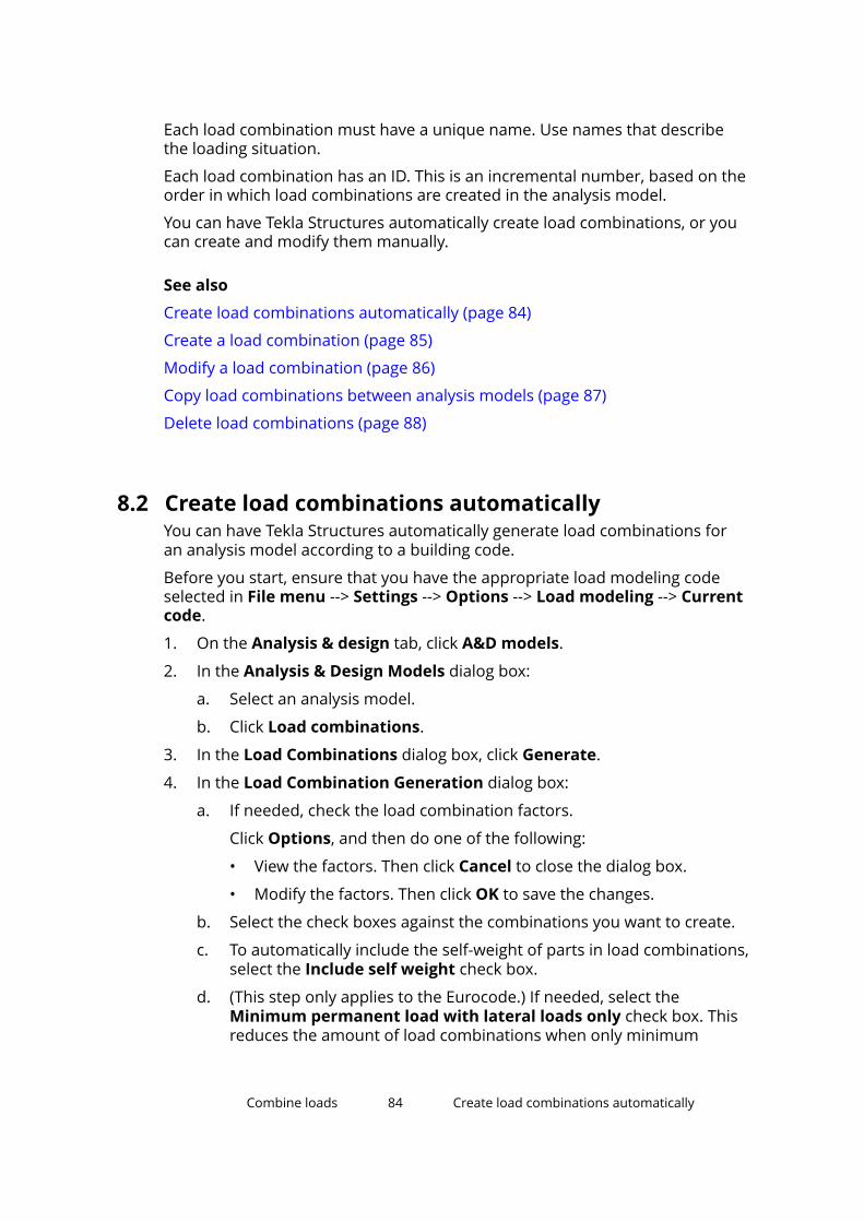
Each load combination must have a unique name. Use names that describethe loading situation.
Each load combination has an ID. This is an incremental number, based on theorder in which load combinations are created in the analysis model.
You can have Tekla Structures automatically create load combinations, or youcan create and modify them manually.
See also
Create load combinations automatically (page 84)
Create a load combination (page 85)
Modify a load combination (page 86)
Copy load combinations between analysis models (page 87)
Delete load combinations (page 88)
8.2 Create load combinations automaticallyYou can have Tekla Structures automatically generate load combinations foran analysis model according to a building code.
Before you start, ensure that you have the appropriate load modeling codeselected in File menu --> Settings --> Options --> Load modeling --> Currentcode.
1. On the Analysis & design tab, click A&D models.
2. In the Analysis & Design Models dialog box:
a. Select an analysis model.
b. Click Load combinations.
3. In the Load Combinations dialog box, click Generate.
4. In the Load Combination Generation dialog box:
a. If needed, check the load combination factors.
Click Options, and then do one of the following:
• View the factors. Then click Cancel to close the dialog box.
• Modify the factors. Then click OK to save the changes.
b. Select the check boxes against the combinations you want to create.
c. To automatically include the self-weight of parts in load combinations,select the Include self weight check box.
d. (This step only applies to the Eurocode.) If needed, select theMinimum permanent load with lateral loads only check box. Thisreduces the amount of load combinations when only minimum
Combine loads 84 Create load combinations automatically

permanent loading needs to be considered in lateral loadingsituations.
e. Click OK to create the load combinations.
If the analysis model has imperfection loads, Tekla Structuresautomatically creates load combinations with both the positive andnegative directions (x and -x, or y and -y).
5. In the Load Combinations dialog box, click OK to save the loadcombinations.
See also
Set the load modeling code (page 16)
Load combination factors (page 107)
Load combination types (page 108)
Create a load combination (page 85)
Modify a load combination (page 86)
Delete load combinations (page 88)
8.3 Create a load combinationIf needed, you can create load combinations for an analysis model one by one.
Before you start, ensure that you have the appropriate load modeling codeselected in File menu --> Settings --> Options --> Load modeling --> Currentcode.
1. On the Analysis & design tab, click A&D models.
2. In the Analysis & Design Models dialog box:
a. Select an analysis model.
b. Click Load combinations.
3. In the Load Combinations dialog box, click New.
4. In the Load Combination dialog box:
a. Select a load combination type from the Type list.
b. Enter a unique name for the load combination.
c. Use the arrow buttons to move load groups between the Loadgroups list and the Load combination table.
d. If needed, modify the signs (+ or -) and combination factors in theLoad combination table by clicking a value.
e. Click Apply to create the load combination.
Combine loads 85 Create a load combination

f. If needed, repeat steps a–e to create more load combinations.
g. Click OK to create the last load combination and close the dialog box.
5. In the Load Combinations dialog box, click OK to save the loadcombinations.
See also
Set the load modeling code (page 16)
Load combination types (page 108)
Load combination factors (page 107)
Create load combinations automatically (page 84)
Modify a load combination (page 86)
Delete load combinations (page 88)
8.4 Modify a load combinationYou can modify the load combinations of an analysis model by changing theload combination name and factors.
You cannot change the load combination type or ID, or add or remove loadgroups after you have created the load combination.
1. On the Analysis & design tab, click A&D models.
2. In the Analysis & Design Models dialog box:
a. Select an analysis model.
b. Click Load combinations.
3. In the Load Combinations dialog box:
a. To change the name of a load combination, select it and enter a newname.
b. To change a load combination factor, select it and enter a new value.
c. Click OK to save the changes.
See also
Create load combinations automatically (page 84)
Create a load combination (page 85)
Copy load combinations between analysis models (page 87)
Delete load combinations (page 88)
Combine loads 86 Modify a load combination

8.5 Copy load combinations between analysis modelsYou can copy load combinations between analysis models within a physicalmodel. You can also copy between physical models if they have the sameenvironment and load groups.
First you need to save the load combinations that you want to copy to a .lcofile. If you want to make the load combinations available in another physicalmodel, you need to copy the .lco file to the \attributes folder of thedestination model, or to the project or firm folder. Then you can load the loadcombinations to another analysis model.
Save load combinations for later useYou can save the load combinations of an analysis model for later use in otheranalysis models.
1. On the Analysis & design tab, click A&D models.
2. In the Analysis & Design Models dialog box:
a. Select an analysis model.
b. Click Load combinations.
3. In the Load Combinations dialog box:
a. Enter a name for the saved load combinations in the box next to Saveas.
b. Click Save as.
Tekla Structures saves the load combinations as a .lco file in the\attributes folder under the current model folder.
4. Click OK to close the dialog boxes.
Copy load combinations from another analysis modelYou can copy load combinations from another analysis model that has thesame load groups and environment.
1. Ensure that the load combinations you want to copy have been saved ina .lco file.
2. Check that the .lco file is located in the \attributes folder under thecurrent model folder, or in the project or firm folder. If not, copy the .lcofile.
3. If you are copying load combinations between two physical models, openthe model to copy to. If you are copying within a physical model, reopenthe model.
Combine loads 87 Copy load combinations between analysis models

4. On the Analysis & design tab, click A&D models.
5. In the Analysis & Design Models dialog box:
a. Select the analysis model to copy to.
b. Click Load combinations.
6. In the Load Combinations dialog box:
a. Select a load combinations file (.lco) from the list next to Load.
b. Click Load.
7. Click OK to close the dialog boxes.
8.6 Delete load combinationsYou can delete load combinations one by one, or several selected or all loadcombinations of an analysis model at once.
1. On the Analysis & design tab, click A&D models.
2. In the Analysis & Design Models dialog box:
a. Select the analysis model whose load combinations you want todelete.
b. Click Load combinations.
3. In the Load Combinations dialog box, do one of the following:
• Select the load combination to delete, and then click Remove.
• Hold down the Ctrl or Shift key and select the load combinations todelete. Then click Remove.
• To delete all load combinations, click Remove all.
4. Click OK to close the dialog boxes.
See also
Modify a load combination (page 86)
Create load combinations automatically (page 84)
Create a load combination (page 85)
Combine loads 88 Delete load combinations

9 Work with analysis and designmodels
This section explains how to export, merge, and view analysis and designmodels and how to save and view analysis results.
Click the links below to find out more:
Check warnings about an analysis model (page 89)
Export an analysis model (page 90)
Merge analysis models using analysis applications (page 91)
Save analysis results (page 93)
View the analysis results of a part (page 94)
Show analysis class in model views (page 95)
Show analysis bar, member, and node numbers (page 95)
Show the utilization ratio of parts (page 96)
9.1 Check warnings about an analysis modelIf there were problems in creating an analysis model, Tekla Structures shows awarning sign in the Analysis & Design Models dialog box when you select theanalysis model.
1. On the Analysis & design tab, click A&D models.
2. In the Analysis & Design Models dialog box:
a. Select an analysis model.
b. If a warning sign appears, click Display warnings.
Work with analysis and design models 89 Check warnings about an analysis model

3. In the warning dialog box, click Details to find out more.
Tekla Structures displays a list of warnings:
• If you select a row with an object ID, Tekla Structures highlights thecorresponding object in the physical model.
• If you right-click a row with an object ID, you can access the object’smenu.
See also
Create analysis models (page 47)
Work with analysis and design models (page 89)
9.2 Export an analysis modelTo run structural analysis on a Tekla Structures analysis model using ananalysis application, you need to export the analysis model into a folder. Bydefault, the export folder is the current model folder. If you have a direct linkto an analysis application, and you export an analysis model from TeklaStructures using that particular analysis application, the analysis model isopened in the application.
1. On the Analysis & design tab, click A&D models.
2. If needed, define the export folder.
Work with analysis and design models 90 Export an analysis model

a. In the Analysis & Design Models dialog box, select the analysismodel to export, and then click Properties.
b. In the Analysis Model Properties dialog box, click Browse forexport folder on the Analysis model tab.
c. In the Browse For Folder dialog box, browse for the export folder,and then click OK.
d. Click OK to save the export folder settings with the analysis modelproperties.
3. In the Analysis & Design Models dialog box:
a. Select the analysis model to export.
b. Click Export.
See also
Structural analysis workflow in Tekla Structures (page 13)
Work with analysis and design models (page 89)
9.3 Merge analysis models using analysis applicationsYou can merge Tekla Structures analysis models with models in some externalanalysis applications. This means that you can make changes to TeklaStructures physical and analysis models even after you have exported them toan analysis application, and still keep the additions you have made to theexported models in the analysis application.
For example, you can create a Tekla Structures model, create an analysismodel of it, export the analysis model to an analysis application, add specialloads to the model in the analysis application, and then run the analysis. If youthen need to make changes to the physical or analysis model in TeklaStructures, you can merge models in the analysis application. If you do notmerge models and you re-export the changed Tekla Structures analysis modelto the analysis application, you will lose the additions you have made to themodel in the analysis application.
For more information, see Analysis and design systems.
Merge analysis models using SAP2000You can merge Tekla Structures analysis models with models in SAP2000.
Work with analysis and design models 91 Merge analysis models using analysis applications

By default, Tekla Structures and SAP2000 analysis models are not merged. Thismeans that a new SAP2000 model is created always when you export a TeklaStructures analysis model to SAP2000.
If you choose to merge a Tekla Structures analysis model with a model inSAP2000, the changes in the Tekla Structures physical or analysis model aremerged to the model in SAP2000. Additional objects and definitions, such asparts, bars, loads, and load combinations, created in SAP2000 are retained inSAP2000. Additional objects created in SAP2000 cannot be imported to TeklaStructures, but they are taken into account in the analysis. They affect theanalysis results, which you can import to Tekla Structures.
When exported to SAP2000, the objects created in Tekla Structures will receivea prefix "_" to their names. The prefix distinguishes the objects created in TeklaStructures from the objects created in SAP2000.
Additional loads created in SAP2000 will be added to the load combinationsthat are created in SAP2000. If you add additional loads to the loadcombinations that are created in Tekla Structures, the loads will be removedfrom these load combinations when you merge models and export a TeklaStructures analysis model to SAP2000.
Merging Tekla Structures and SAP2000 analysis models helps in retaining theexisting analysis node and bar numbers in SAP2000.
• Existing node numbers are kept if the node coordinates stay the same.
• Existing bar numbers are kept if the start and end node numbers stay thesame.
• Old node and bar numbers are not re-used.
Limitations
Changes in the following properties in Tekla Structures are not updated inSAP2000 even if you merge models:
• The profile and material properties of parts if a profile or material namealready exists in SAP2000
• Load combinations if the name of the load combination already exists inSAP2000
To keep the changes made in SAP2000 when you re-export a changed TeklaStructures analysis model, you can adjust the profile and material propertiesand the load combination type in SAP2000.
If you change the support condition settings in SAP2000 and then re-export aTekla Structures analysis model, you will lose these changes.
How to merge a Tekla Structures analysis model with amodel in SAP20001. On the Analysis & design tab, click A&D models.
Work with analysis and design models 92 Merge analysis models using analysis applications

2. In the Analysis & Design Models dialog box, do one of the following:
• To merge an existing analysis model, select the analysis model, andthen click Properties to check and modify its properties.
• To create a new analysis model and merge it, click New.
3. In the Analysis Model Properties dialog box:
a. In the Analysis application list, select SAP2000.
b. Click More settings on the Analysis model tab.
c. In the Model merging with analysis application list, select Enabled.
d. If you are merging a new analysis model, modify the other analysismodel properties if needed.
e. Click OK to save the analysis model properties.
Tekla Structures merges the models the next time you export the TeklaStructures analysis model to SAP2000 to run the analysis.
Reset merged analysis modelsYou can reset model merging between Tekla Structures and external analysisapplications.
1. On the Analysis & design tab, click A&D models.
2. In the Analysis & Design Models dialog box:
a. Select the analysis model to reset.
b. Click Properties.
3. In the Analysis Model Properties dialog box:
a. Click More settings on the Analysis model tab.
b. In the Model merging with analysis application list, selectDisabled.
c. Click OK to save the analysis model properties.
9.4 Save analysis resultsWhen you save the analysis results and then save the physical model, TeklaStructures saves the results of all load combinations in a database,analysis_results.db5, in the current model folder.
If you do not want to create the analysis results database analysis_results.db5, set XS_AD_RESULT_DATABASE_ENABLED to FALSEin File menu --> Settings --> Advanced Options --> Analysis & Design .
Work with analysis and design models 93 Save analysis results

Use the following advanced options in File menu --> Settings --> AdvancedOptions --> Analysis & Design to define the analysis member points whoseresults are saved in the database:
• XS_AD_MEMBER_RESULT_DIVISION_COUNT
• XS_AD_MEMBER_RESULT_DISP_DIVISION_COUNT
• XS_AD_MEMBER_RESULT_MIN_DISTANCE
• XS_AD_MEMBER_RESULT_GRID_SIZE
See also
Save analysis results as user-defined attributes of parts (page 94)
Save analysis results as user-defined attributes of partsAfter running the analysis, you can save the maximum axial force, shear force,and bending moment at the part ends as user-defined attributes in the partproperties. You can save the results for each part in an analysis model or forspecific parts.
Before you start, run the analysis.
1. On the Analysis & design tab, click A&D models.
2. In the Analysis & Design Models dialog box:
a. Select an analysis model.
b. Do one of the following:
• To save the results for each part in the analysis model, click Getresults.
• To save the results for specific parts, select the parts in thephysical model, and then click Get results for selected.
See also
View the analysis results of a part (page 94)
Show the utilization ratio of parts (page 96)
9.5 View the analysis results of a partYou can view a part’s analysis results using the user-defined attributes.
Before you start, ensure that you have saved the analysis results using the Getresults or Get results for selected command on the correct analysis model.
1. Double-click a part in the physical model.
Work with analysis and design models 94 View the analysis results of a part

2. In the part properties dialog box, click User-defined attributes on theAttributes tab.
3. In the user-defined attributes dialog box:
• Go to the End Conditions tab to view the analysis results at the partends.
• Go to the Analysis tab to view the utilization ratio of a steel part or therequired area of reinforcement in a concrete part.
To access the analysis results database, use the .NET interface or TeklaStructures’s excel design interface.
See also
Save analysis results as user-defined attributes of parts (page 94)
Save analysis results (page 93)
9.6 Show analysis class in model viewsThe analysis class defines how Tekla Structures handles individual parts in theanalysis. You can show the analysis class of parts in an object group usingdifferent colors in the analysis model.
Before you start, create an object group that includes the parts whose analysisclass you want to show.
1. On the Analysis & design tab, click A&D models.
2. In the Analysis & Design Models dialog box, select an analysis model.
3. On the View tab, click Representation.
4. In the Object Representation dialog box:
a. Select an object group.
b. In the Color column, select Color by analysis type from the list.
c. Click Modify.
See also
Analysis class options and colors (page 126)
9.7 Show analysis bar, member, and node numbersYou can show analysis bar, member, and analysis node numbers in modelviews.
Work with analysis and design models 95 Show analysis class in model views

Use the following advanced options in File menu --> Settings --> AdvancedOptions --> Analysis & Design to define which numbers are shown:
• XS_AD_MEMBER_NUMBER_VISUALIZATION
• XS_AD_NODE_NUMBER_VISUALIZATION
• XS_AD_NODE_NUMBER_BY_Z
Some analysis applications work on analysis members whereas others workon analysis bars. This also affects how analysis models are shown in TeklaStructures model views. Either member numbers or bar numbers are shown.
See also
Analysis model objects (page 9)
Analysis node colors (page 63)
9.8 Show the utilization ratio of partsOnce you have exported an analysis model to an analysis application and runthe analysis, you can view the analysis results. To perform a visual check, youcan use different colors to show the utilization ratio of the steel parts in anobject group in the physical model.
Before you start, ensure that you have saved the analysis results using the Getresults or Get results for selected command on the correct analysis model.
1. Create an object group that includes the parts whose utilization ratio youwant to show.
2. On the View tab, click Representation.
3. In the Object Representation dialog box:
a. Select the object group whose utilization ratios you want to show.
b. In the Color column, select Color by analysis utility check from thelist.
4. In the Utility Ratio Ranges dialog box:
a. Set the ranges of ratio for each of the colors that Tekla Structuresuses to show safe and unsafe parts.
b. Click OK.
5. In the Object Representation dialog box, click Modify.
Work with analysis and design models 96 Show the utilization ratio of parts

Tekla Structures shows the utilization ratio of the steel parts in the selectedanalysis model using the following colors:
See also
Export an analysis model (page 90)
Save analysis results as user-defined attributes of parts (page 94)
View the analysis results of a part (page 94)
Work with analysis and design models 97 Show the utilization ratio of parts

10 Analysis and design settings
This section provides information about the various analysis and designsettings you can modify in Tekla Structures.
Click the links below to find out more:
Load group properties (page 98)
Load properties (page 100)
Load combination properties (page 107)
Analysis model properties (page 110)
Analysis part properties (page 116)
Analysis node properties (page 130)
Analysis rigid link properties (page 132)
Analysis bar position properties (page 134)
Analysis area position properties (page 134)
Analysis area edge properties (page 135)
10.1 Load group propertiesUse the Load Groups dialog box to view, define, and modify the load groupproperties and to work with load groups.
Option DescriptionCurrent The @ character identifies the current load group.
When you create loads in the model, Tekla Structuresadds them to the current load group. You can onlydefine one load group as current.
To change the current load group, select a load groupand click Set current.
Analysis and design settings 98 Load group properties

Option DescriptionName Unique name of the load group.
Use load group names to define the visibility andselectability of loads. For example, you can select,modify, or hide loads based on their load group.
Type The type of a load group is the type of action thatcauses the loads.
Actions causing loads are building code specific anddepend on the load modeling code (page 16) selectedin File menu --> Settings --> Options --> Loadmodeling --> Current code.
Most building codes use some or all of the followingactions and load group types:
• Permanent, dead, and/or prestressing loads
• Live, imposed, traffic, and/or crane loads
• Snow loads
• Wind loads
• Temperature loads
• Accidental and/or earthquake loads
• Imperfection loadsDirection The direction of a load group is the global direction of
the action that causes the loads. Individual loads in aload group retain their own magnitudes in the globalor local x, y, and z directions.
The load group direction affects which loads TeklaStructures combines in a load combination:
• z direction groups are combined with both x and ydirection groups.
• x or y direction groups are not combined with eachother.
Compatible A number that identifies all the load groups that arecompatible with each other.
Incompatible A number that identifies all the load groups that areincompatible with each other.
Color The color that Tekla Structures uses to show the loadsin the group.
See also
Group loads together (page 18)
Analysis and design settings 99 Load group properties

Work with loads and load groups (page 41)
10.2 Load propertiesThis section provides information about the properties of specific loads.
Use the load properties dialog boxes to view, define, and modify the loadproperties. Each load type has its own properties dialog box.
Click the links below to find out more:
Point load properties (page 100)
Line load properties (page 101)
Area load properties (page 102)
Uniform load properties (page 102)
Temperature load properties (page 103)
Wind load properties (page 104)
Load panel settings (page 105)
Point load propertiesUse the Point Load Properties dialog box to view and modify the propertiesof a point load or a bending moment. The file name extension of a point loadproperties file is .lm1.
Option DescriptionLoad group name The load group to which the load belongs.
To view load group properties or to create a new loadgroup, click Load groups.
Magnitude tab Load magnitudes in the x, y, and z directions of thework plane.
Load attachment Indicates if the load is attached to a part.Load-bearing parts Parts to which the load is applied, or not applied, on
the basis of part names or selection filters.Bounding box of theload
Dimensions of the bounding box in the x, y, and zdirections.
Load panel tab See Load panel settings (page 105).
See also
Create a point load (page 25)
Analysis and design settings 100 Load properties
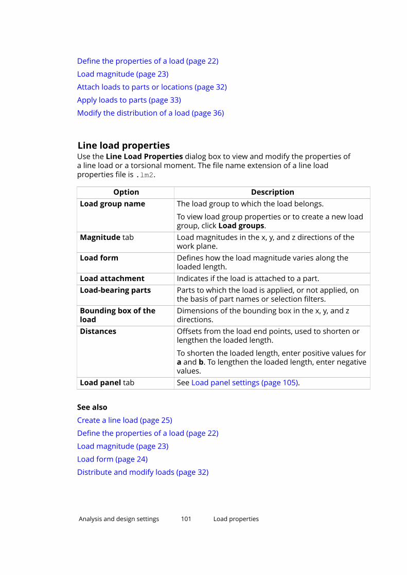
Define the properties of a load (page 22)
Load magnitude (page 23)
Attach loads to parts or locations (page 32)
Apply loads to parts (page 33)
Modify the distribution of a load (page 36)
Line load propertiesUse the Line Load Properties dialog box to view and modify the properties ofa line load or a torsional moment. The file name extension of a line loadproperties file is .lm2.
Option DescriptionLoad group name The load group to which the load belongs.
To view load group properties or to create a new loadgroup, click Load groups.
Magnitude tab Load magnitudes in the x, y, and z directions of thework plane.
Load form Defines how the load magnitude varies along theloaded length.
Load attachment Indicates if the load is attached to a part.Load-bearing parts Parts to which the load is applied, or not applied, on
the basis of part names or selection filters.Bounding box of theload
Dimensions of the bounding box in the x, y, and zdirections.
Distances Offsets from the load end points, used to shorten orlengthen the loaded length.
To shorten the loaded length, enter positive values fora and b. To lengthen the loaded length, enter negativevalues.
Load panel tab See Load panel settings (page 105).
See also
Create a line load (page 25)
Define the properties of a load (page 22)
Load magnitude (page 23)
Load form (page 24)
Distribute and modify loads (page 32)
Analysis and design settings 101 Load properties
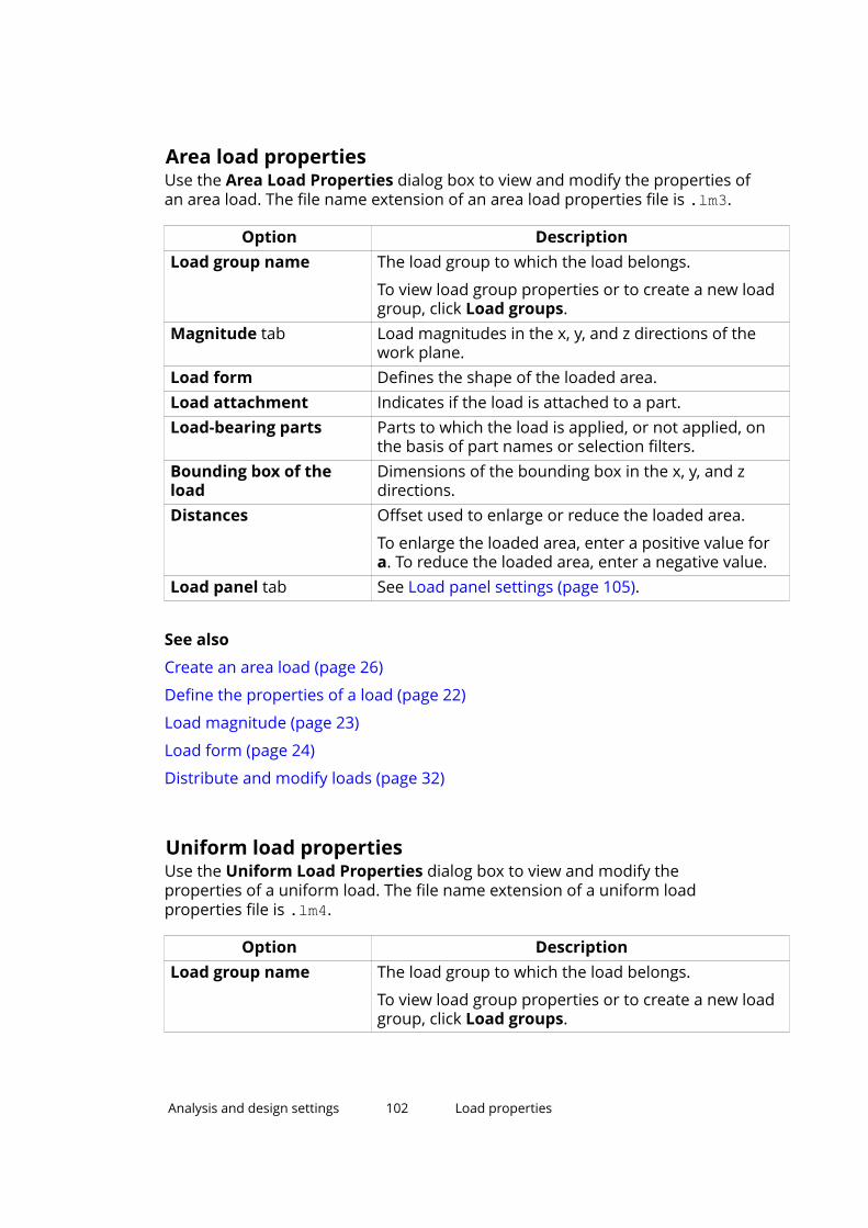
Area load propertiesUse the Area Load Properties dialog box to view and modify the properties ofan area load. The file name extension of an area load properties file is .lm3.
Option DescriptionLoad group name The load group to which the load belongs.
To view load group properties or to create a new loadgroup, click Load groups.
Magnitude tab Load magnitudes in the x, y, and z directions of thework plane.
Load form Defines the shape of the loaded area.Load attachment Indicates if the load is attached to a part.Load-bearing parts Parts to which the load is applied, or not applied, on
the basis of part names or selection filters.Bounding box of theload
Dimensions of the bounding box in the x, y, and zdirections.
Distances Offset used to enlarge or reduce the loaded area.
To enlarge the loaded area, enter a positive value fora. To reduce the loaded area, enter a negative value.
Load panel tab See Load panel settings (page 105).
See also
Create an area load (page 26)
Define the properties of a load (page 22)
Load magnitude (page 23)
Load form (page 24)
Distribute and modify loads (page 32)
Uniform load propertiesUse the Uniform Load Properties dialog box to view and modify theproperties of a uniform load. The file name extension of a uniform loadproperties file is .lm4.
Option DescriptionLoad group name The load group to which the load belongs.
To view load group properties or to create a new loadgroup, click Load groups.
Analysis and design settings 102 Load properties

Option DescriptionMagnitude tab Load magnitudes in the x, y, and z directions of the
work plane.Load attachment Indicates if the load is attached to a part.Load-bearing parts Parts to which the load is applied, or not applied, on
the basis of part names or selection filters.Bounding box of theload
Dimensions of the bounding box in the x, y, and zdirections.
Distances Offset used to enlarge or reduce the loaded area.Load panel tab See Load panel settings (page 105).
See also
Create a uniform load (page 26)
Define the properties of a load (page 22)
Load magnitude (page 23)
Distribute and modify loads (page 32)
Temperature load propertiesUse the Temperature Load Properties dialog box to view and modify theproperties of a temperature load or a strain. The file name extension of atemperature load properties file is .lm6.
Option DescriptionLoad group name The load group to which the load belongs.
To view load group properties or to create a new loadgroup, click Load groups.
Temperature change foraxial elongation
Temperature change in the part.
Temperaturedifferential from side toside
Difference in temperature between the left side andthe right side of a part.
Temperaturedifferential from top tobottom
Difference in temperature between the top surfaceand the bottom surface of a part.
Initial axial elongation Axial strain of a part.
A positive value indicates elongation, a negative valueindicates shrinkage.
Load attachment Indicates if the load is attached to a part.
Analysis and design settings 103 Load properties

Option DescriptionLoad-bearing parts Parts to which the load is applied, or not applied, on
the basis of part names or selection filters.Bounding box of theload
Dimensions of the bounding box in the x, y, and zdirections.
See also
Create a temperature load or a strain (page 27)
Define the properties of a load (page 22)
Apply loads to parts (page 33)
Wind load propertiesUse the Wind Load Generator (28) dialog box to view and modify theproperties of wind loads.
Option DescriptionWind load direction The main direction of the wind.
The options are:
• Global X
• Global -X
• Global Y
• Global -Y
• Global X, -X, Y, -Y (for all directions)Nominal wind pressure The nominal value of wind pressure.Top level The highest level of the wind loads.Bottom level The lowest level of the wind loads.Ground level The level of the ground around the building.Part names Parts to which the load is applied, or not applied.
See also Define load-bearing parts by name (page 33).Front The external exposure factors for the windward,
leeward, and side walls.
A positive value indicates pressure, a negative valueindicates suction.
Left sideBackRight sideInternal The internal exposure factor.Z profile tab The distribution of wind load along the height of the
building, in terms of pressure factors. Starts from theground level.
Analysis and design settings 104 Load properties

Option DescriptionGlobal X, Global Y,Global -X, Global -Y tabs
A tab for each wind direction, where you can definezones for concentrated corner loads on each wall.
Each zone is the height of the wall. Define the width ofthe zone using either dimensions or proportions. Youcan define up to five zones for each wall.
Walls are numbered according to the order you pickpoints to indicate the shape of the building on thebottom level.
See also
Create wind loads (page 28)
Wind load examples (page 29)
Load panel settingsUse the options on the Load panel tab in a load properties dialog box tomodify the way Tekla Structures distributes the load.
Option DescriptionSpanning Defines the directions in which Tekla Structures
distributes the load.
• Single distributes the load only in the direction ofthe primary axis.
• Double distributes the load along the primary andsecondary axes.
Primary axis direction Defines the direction of the primary axis using one ofthe following methods:
• A value (1) in the x, y, or z box distributes the loadin the corresponding global direction.
• Values in multiple boxes distribute the loadbetween the corresponding global directions. Thevalues are the components of the direction vector.
• Clicking Parallel to part, or Perpendicular topart, and then selecting a part in the model alignsthe primary axis direction with the part.
If Spanning is Double, you need to define the primaryaxis direction to be able to manually define theprimary axis weight.
To check the primary axis direction of a selected loadin a model view, click Show direction on selected
Analysis and design settings 105 Load properties
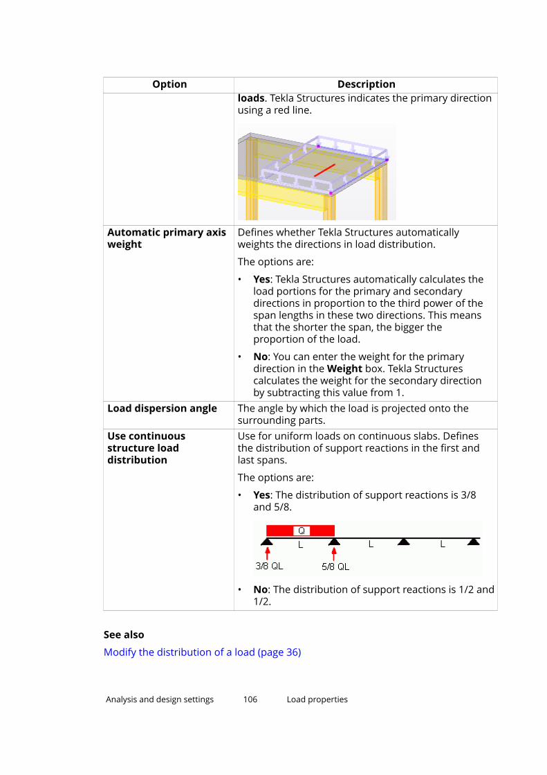
Option Descriptionloads. Tekla Structures indicates the primary directionusing a red line.
Automatic primary axisweight
Defines whether Tekla Structures automaticallyweights the directions in load distribution.
The options are:
• Yes: Tekla Structures automatically calculates theload portions for the primary and secondarydirections in proportion to the third power of thespan lengths in these two directions. This meansthat the shorter the span, the bigger theproportion of the load.
• No: You can enter the weight for the primarydirection in the Weight box. Tekla Structurescalculates the weight for the secondary directionby subtracting this value from 1.
Load dispersion angle The angle by which the load is projected onto thesurrounding parts.
Use continuousstructure loaddistribution
Use for uniform loads on continuous slabs. Definesthe distribution of support reactions in the first andlast spans.
The options are:
• Yes: The distribution of support reactions is 3/8and 5/8.
• No: The distribution of support reactions is 1/2 and1/2.
See also
Modify the distribution of a load (page 36)
Analysis and design settings 106 Load properties

10.3 Load combination propertiesThis section provides information about the settings that control the loadcombination process.
Click the links below to find out more:
• Load modeling code options (page 107)
• Load combination factors (page 107)
• Load combination types (page 108)
Load modeling code optionsThese are the load modeling codes available in Tekla Structures in File menu --> Settings --> Options --> Load modeling --> Current code:
Option DescriptionEurocode European codeBritish British codeAISC (US) American Institute of Steel Construction, US codeUBC (US) Uniform building code, US codeCM66 (F) French code for steel structuresBAEL91 (F) French code for concrete structuresIBC (US) International building code, US codeACI American Concrete Institute’s publication 318
Each of the available codes has a separate tab in the Options dialog box. TheOptions dialog box lists the partial safety factors in limit states and othercombination factors for the code, based on load group types. For theEurocode, you can also set the reliability class factor and the formula to beused in load combination.
See also
Set the load modeling code (page 16)
Load combination factors (page 107)
Load combination factorsIn the load combination process, Tekla Structures uses partial safety factorsand, for example, reduction factors on load groups to create loadcombinations.
Analysis and design settings 107 Load combination properties

The partial safety factors needed in the limit state design are:
• Unfavorable partial safety factor in the ultimate limit state (γsup)
• Favorable partial safety factor in the ultimate limit state (γinf)
• Unfavorable partial safety factor in the serviceability limit state (γsup)
• Favorable partial safety factor in the serviceability limit state (γinf)
Depending on the codes you use, you may need to use other combinationfactors. For example, the Eurocode contains three reduction factors (ψ0, ψ1, ψ2).Reduction factors exclude the impractical effects of simultaneous loads.
You can use values for load combination factors that are building code specificor user-defined.
See also
Set the load modeling code (page 16)
Use non-standard load combination factors (page 17)
Load combination typesYou can perform several load combination types which vary according to thebuilding code you use.
Use the Load Combination Generation dialog box, or the Load Combinationdialog box, to select the load combination types you want to create. Theoptions are:
Combination type Description Applies toUltimate limit state(ULS)
Combines load groups that occurpersistently and transiently. Uses thepartial safety factors of the ultimatelimit state when combining loads.
Eurocode,British, AISC(US)
Serviceability limit state(SLS)
Combines load groups that occurquasi-permanently. Uses the partialsafety factors of the serviceabilitylimit state when combining loads.
Eurocode, AISC(US)
Serviceability limit state– Rare (SLS RC)
Combines load groups that occurquasi-permanently and rarely. Usesthe partial safety factors of theserviceability limit state whencombining loads.
Eurocode
Serviceability limit state– Quasi-permanent (SLSQP)
Combines load groups that occurquasi-permanently. Uses the partialsafety factors of the serviceabilitylimit state when combining loads.
Eurocode
Analysis and design settings 108 Load combination properties

Combination type Description Applies toNormal loads Combines load groups and uses
factors according to the French codesCM66 or BAEL91.
CM66, BAEL91Extreme loads CM66Displacement loads CM66Accidental loads CM66,
EurocodeUltimate loads BAEL91Ultimate accidentalloads
BAEL91
Earthquake loads Combines load groups and usesfactors according to the Eurocode.
Eurocode
Loads for publicstructures
Combines load groups according tothe US IBC code (InternationalBuilding Code).
IBC (US)
Loads for publicstructures with driftedsnow
IBC (US)
Loads for non publicstructures
IBC (US)
Loads for non publicstructures with driftedsnow
IBC (US)
Loads for public nonconcrete and masonrystructures
Combines load groups according tothe US UBC code (Uniform BuildingCode).
UBC (US)
Loads for public nonconcrete and masonrystructures with driftedsnow
UBC (US)
Loads for non concreteand masonry structures
UBC (US)
Loads for non concreteand masonry structureswith drifted snow
UBC (US)
Loads for publicconcrete and masonrystructures
UBC (US)
Loads for publicconcrete and masonrystructures with driftedsnow
UBC (US)
Loads for concrete andmasonry structures
UBC (US)
Analysis and design settings 109 Load combination properties
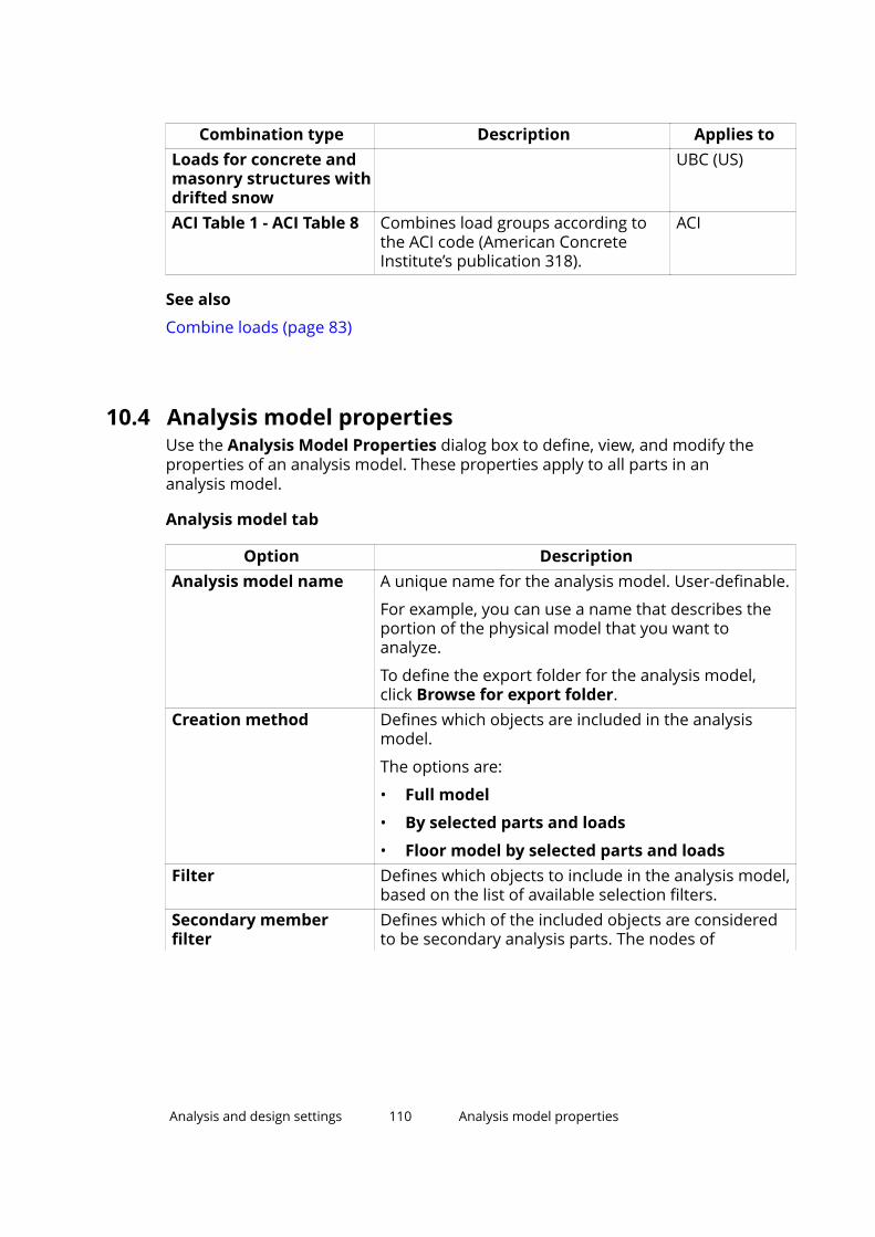
Combination type Description Applies toLoads for concrete andmasonry structures withdrifted snow
UBC (US)
ACI Table 1 - ACI Table 8 Combines load groups according tothe ACI code (American ConcreteInstitute’s publication 318).
ACI
See also
Combine loads (page 83)
10.4 Analysis model propertiesUse the Analysis Model Properties dialog box to define, view, and modify theproperties of an analysis model. These properties apply to all parts in ananalysis model.
Analysis model tab
Option DescriptionAnalysis model name A unique name for the analysis model. User-definable.
For example, you can use a name that describes theportion of the physical model that you want toanalyze.
To define the export folder for the analysis model,click Browse for export folder.
Creation method Defines which objects are included in the analysismodel.
The options are:
• Full model
• By selected parts and loads
• Floor model by selected parts and loadsFilter Defines which objects to include in the analysis model,
based on the list of available selection filters.Secondary memberfilter
Defines which of the included objects are consideredto be secondary analysis parts. The nodes of
Analysis and design settings 110 Analysis model properties

Option Descriptionsecondary analysis parts can move more freely thanthe ones of primary analysis parts.
To have Tekla Structures automatically recognize, forexample, skewed parts as secondary parts, selectAuto-detect secondary members.
If you change this setting for an existing analysismodel, select the Reapply to all parts check box toapply the change to all parts in the analysis model. Ifyou do not select the check box, Tekla Structures willuse the new setting only for the new parts in theanalysis model.
Analysis application The analysis application or format used in the analysisof the analysis model.
To use the same application or format by default forother new analysis models, select the Set as thedefault check box.
More settings: Click to show the following settings.Use rigid links Use to allow or prevent rigid links in the analysis
model.
The options are:
• Enabled
Rigid links are created if they are needed toconnect analysis parts.
• Disabled, with keep axis: Default
No rigid links are created. The Keep axis positionsettings of the analysis parts are not changed.
• Disabled, with keep axis: No
No rigid links are created. The Keep axis positionsettings of the connected analysis parts arechanged to No.
Default keep axis forsecondary members
Defines whether the axis of the secondary analysisparts is free to move.
The options are:
• No
• Yes - Ignore out-of-plane eccentricities
• Yes
• Yes - Keep end positions alsoAnalysis model rules Click to create rules to define how Tekla Structures
handles individual parts in the analysis model, and
Analysis and design settings 111 Analysis model properties

Option Descriptionhow parts are connected with each other in theanalysis.
Curved beams Defines whether beams are analyzed as curved beamor as straight segments. Select either:
• Split into straight segments
• Use curved member
Use the advanced optionXS_AD_CURVED_BEAM_SPLIT_ACCURACY_MM in Filemenu --> Settings --> Advanced Options --> Analysis& Design to define how closely straight segmentsfollow the curved beam.
Consider twin profiles Defines whether twin profiles are considered as onepart (Enabled) or as two parts (Disabled) in theanalysis.
Member axis location Defines the location of each analysis part in relation tothe corresponding physical part.
The options are:
• Neutral axis
The neutral axis is the analysis axis for all parts.The location of the analysis axis changes if theprofile of the part changes.
• Reference axis (eccentricity by neutral axis)
The part reference line is the analysis axis for allparts. The location of the neutral axis defines axiseccentricity.
• Reference axis
The part reference line is the analysis axis for allparts.
• Model default
The analysis axis of each part is definedindividually according to the analysis partproperties.
To define the axis location of specific parts, use thePosition tab in the appropriate analysis partproperties dialog box.
If you select Neutral axis, Tekla Structures takes thepart location and end offsets into account when itcreates nodes. If you select either of the Referenceaxis options, Tekla Structures creates nodes at partreference points.
Analysis and design settings 112 Analysis model properties

Option DescriptionMember end releasemethod by connection
Defines whether the support conditions of parts (No)or connections (Yes) are used.
Automatic update Defines if the analysis model is updated according tothe changes in the physical model.
The options are:
• Yes - Physical model changes are considered
• No - Physical model changes are ignoredModel merging withanalysis application
Use when changes occur in the Tekla Structuresphysical or analysis model that has already beenexported to the analysis application.
Defines whether the changed analysis model ismerged with the previously exported model in theanalysis application.
The options are:
• Disabled
Models are not merged. Additions made in theanalysis application to the previously exportedmodel are lost. A new model is created every timeyou export the analysis model to the analysisapplication.
• Enabled
Models are merged. Additions made in the analysisapplication to the previously exported model areretained when you re-export the analysis model tothe analysis application. The model in the analysisapplication is updated with the changes from TeklaStructures.
Analysis tab
Option DescriptionAnalysis method Defines whether second order stresses are taken into
consideration.
The options are:
• 1st order
Linear analysis method.
• P-Delta
A simplified second order analysis method. Thismethod gives accurate results when deflections aresmall.
Analysis and design settings 113 Analysis model properties

Option Description• Non-linear
Non-linear analysis method.Maximum number ofiterations
Tekla Structures repeats second order iteration until itreaches one of these values.
Accuracy of theiterationModal analysis model Select Yes to create a modal analysis model and to use
modal analysis properties instead of static loadcombinations.
Job tab
Defines the job information in STAAD.Pro reports.
Output tab
Defines the contents of the STAAD.Pro analysis results file.
Seismic tab
Use the Seismic tab to define which building code to follow in the seismicanalysis and the properties required by the seismic analysis. These propertiesvary depending on the code you select.
Option DescriptionType The building code to use to generate seismic loads.
The options are:
• None: Seismic analysis not run.
• UBC 1997: Uniform Building Code 1997
• UBC 1994: Uniform Building Code 1994
• IBC 2000: International Building Code 2000
• IS 1893-2002: Indian Standard. Criteria forEarthquake Resistant Design of Structures
• IBC 2003: International Building Code 2003
• IBC 2006: International Building Code 2006
• IBC 2006 (ZIP): International Building Code 2006,with an option to add a ZIP code in the properties
• IBC 2006 (Longitude/Latitude): InternationalBuilding Code 2006, with an option to addlongitude and latitude information in theproperties
• AIJ: Japanese code
Analysis and design settings 114 Analysis model properties

Option Description• Response spectrum: Response spectrum
specificationSeismic properties Depending on the code you select, you can define
various seismic properties.
Seismic masses tab
The loads and load groups included in the seismic analysis.
Modal analysis tab
Use the Modal analysis tab to define the properties required by the modalanalysis.
Option DescriptionCount of modes The number of natural mode shapes in the structure.Max frequency The maximum natural resonant frequency of the
structure.Modal analysis masses The loads and load groups included in the modal
analysis.
Design tabs
Use the Design tabs for steel, concrete, and timber to define the codes andmethods to use in structural design. The design options available varydepending on the material.
Option DescriptionDesign code Design codes for different materials.
The design code options available vary depending onthe analysis application you use.
Design method The material-specific principle used to comparestresses and material capacities.
The options are:
• None
Tekla Structures only runs a structural analysis andcreates data on stresses, forces, anddisplacements.
Available for steel, concrete, and timber.
• Check design
Tekla Structures checks whether the structuresfulfill the criteria in the design code (whether crosssections are adequate).
Available for steel and timber.
Analysis and design settings 115 Analysis model properties

Option Description• Calculate required area
Tekla Structures defines the required area ofreinforcement.
Available for concrete.Design properties The design code and method specific design
properties of the analysis model that apply to all partsin the analysis model.
When you select a design code and method for amaterial, Tekla Structures lists the design properties inthe lower part of the Design tab.
To change the value of a particular property, click onan entry in the Value column.
The units depend on the settings in File menu -->Settings --> Options --> Units and decimals.
To change the design properties of a specific part, usethe Design tab in the appropriate analysis partproperties dialog box.
See also
Create analysis models (page 47)
Define basic properties for an analysis model (page 47)
Modify the properties of an analysis model (page 55)
10.5 Analysis part propertiesUse the options in a part’s analysis properties dialog box (for example, BeamAnalysis Properties) to define how Tekla Structures handles the part in theanalysis. The settings you have available in the dialog box vary depending onthe part type and analysis class. The table below lists all settings regardless ofthe part type and the analysis class.
Analysis tab
Use the Analysis tab to define the analysis properties of a part.
Option DescriptionClass Defines how the part is handled in the analysis.
The selected Class defines which analysis propertiesare available. For example, plates have differentproperties from columns.
Analysis and design settings 116 Analysis part properties

Option DescriptionFilter
(Rigid diaphragmproperties)
Only available when the Class is Contour plate - Rigiddiaphragm or Slab - Rigid diaphragm.
Defines the filter used when filtering objects for a rigiddiaphragm.
Nodes that belong to a part matching the filter will beconnected to the rigid diaphragm. For example, youcan use column_filter to connect only column nodesto rigid diaphragms.
Built-up section mode Indicates the role of the part in a built-up section thatconsists of a main part and one or more sub-parts. Inthe analysis, sub-parts are merged to the main part.
The options are:
• Automatic
• Not part of built-up section
Disconnects the part from a built-up section.
• Main part of built-up section
Always use to define the main part of a built-upsection.
• Sub-part of built-up section
• Beam sub-part of built-up section
Defines that the part is a part of the built-upsection when the main part of the built-up sectionis a beam.
• Column sub-part of built-up section
Defines that the part is a part of the built-upsection when the main part of the built-up sectionis a column.
Design group Defines to which design group the part belongs. Usedin optimization.
Automatic update Defines if the analysis part is updated according to thechanges in the physical model.
The options are:
• Yes - Physical model changes are considered
• No - Physical model changes are ignored
Start releases tab, End releases tab
Use the Start releases and End releases tabs to define the supportconditions and the degrees of freedom for the part ends.
Analysis and design settings 117 Analysis part properties
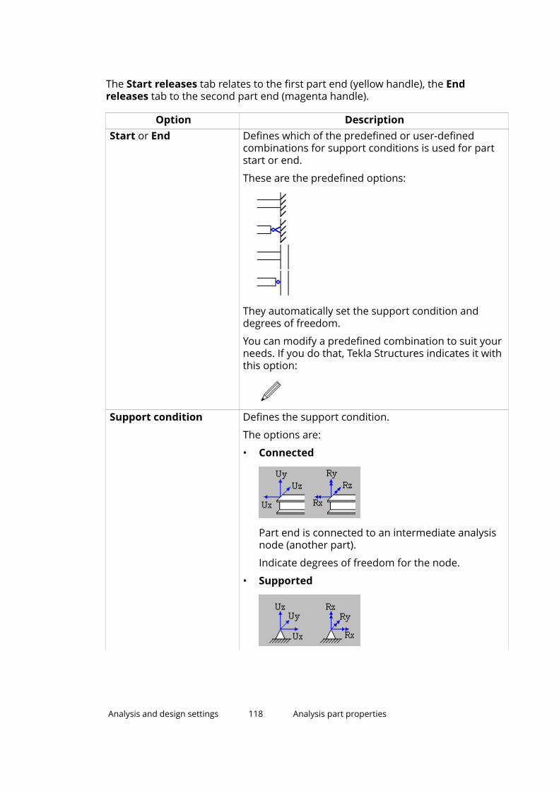
The Start releases tab relates to the first part end (yellow handle), the Endreleases tab to the second part end (magenta handle).
Option DescriptionStart or End Defines which of the predefined or user-defined
combinations for support conditions is used for partstart or end.
These are the predefined options:
They automatically set the support condition anddegrees of freedom.
You can modify a predefined combination to suit yourneeds. If you do that, Tekla Structures indicates it withthis option:
Support condition Defines the support condition.
The options are:
• Connected
Part end is connected to an intermediate analysisnode (another part).
Indicate degrees of freedom for the node.
• Supported
Analysis and design settings 118 Analysis part properties

Option DescriptionPart end is the ultimate support for asuperstructure (for example, the foot of a columnin a frame).
Indicate degrees of freedom for the support.Rotation Only available if Support condition is Supported.
Defines whether the support is rotated.
The options are:
• Not rotated
• Rotated
If you select Rotated, you can define the rotationaround the local x or y axis, or you can set the rotationby the current work plane by clicking Set rotation bycurrent work plane.
Ux
Uy
Uz
Define the translational degrees of freedom(displacements) in the global x, y, and z directions.
The options are:
• Free
• Fixed
• Spring
If you select Spring, enter the translational springconstant. The units depend on the settings in Filemenu --> Settings --> Options --> Units anddecimals.
Rx
Ry
Rz
Define the rotational degrees of freedom (rotations) inthe global x, y, and z directions.
The options are:
• Pinned
• Fixed
• Spring
• Partial release
If you select Spring, enter the rotational springconstant. The units depend on the settings in Filemenu --> Settings --> Options --> Units anddecimals.
Use Partial release to specify if the degree ofconnectivity is between fixed and pinned. Enter avalue between 0 (fixed) and 1 (pinned).
Analysis and design settings 119 Analysis part properties

Composite tab
Use the Composite tab with STAAD.Pro to define the analysis properties of theslab in a composite beam.
Option DescriptionComposite beam Defines whether the composition is a:
• Non-composite beam
• Composite beam
• Automatic composite beamMaterial Defines the material of the slab.Thickness Defines the thickness of the slab.Effective slab width Defines if the effective slab width is calculated
automatically or based on the values you enter.
You can define different values for the left and rightside of the beam.
Automatic values are calculated in relation to the spanlength.
Spanning tab
Use the Spanning tab to define the analysis and load distribution propertiesof a one-way or two-way slab system.
Option DescriptionSpanning Defines in which directions the part carries loads.
The options are:
• Single spanning plate carries loads in the directionof the primary axis. Beams or columns parallel tothe spanning direction are not connected to thepart, and will not carry loads from the part.
• Double spanning part carries loads along theprimary and secondary axes. Beams or columns inboth directions will carry loads from the part.
Primary axis direction Defines the direction of the primary axis in one of thefollowing ways:
• Enter 1 in the box (x, y, or z) which is parallel to theprimary axis direction.
• Enter values in multiple boxes to define thecomponents of a direction vector.
• Click Parallel to part, and then select a part in themodel that is parallel to the direction.
Analysis and design settings 120 Analysis part properties

Option Description• Click Perpendicular to part, and then select a part
in the model that is perpendicular to the direction.
To check the primary spanning direction of a selectedpart in a model view, click Show direction onselected members. Tekla Structures indicates theprimary direction using a red line.
Loading tab
Use the Loading tab to include a part as loads in analysis models.
Option DescriptionGenerate self weightload
Analysis models include the part weight, for example adeck, as a load even if the part is not otherwiseincluded in the analysis models.
If the part is included in an analysis model, so is itsself-weight. The option No works only with theanalysis classes Ignore and Rigid diaphragm.
List boxes for additionalloads
Enter slab live load or additional self-weight (screed,services) using three additional loads with a loadgroup name and magnitude. The directions of theseloads follow the direction of the load group to whichthey belong.
Part names Use this filter to ensure that the area load from theslab is transferred to the correct parts, for example,beams supporting the slab. Typically, you would enterthe beam name as the filter value.
Use continuousstructure loaddistribution
Use to assign most of the load to the middle supportson continuous structures.
Analysis and design settings 121 Analysis part properties

Design tab
Use the Design tab in the analysis part properties dialog box to view andmodify the design properties of an individual part in an analysis model. Designproperties are properties which can vary, according to the design code and thematerial of the part (for example, design settings, factors, and limits).
Position tab
Use the Position tab to define the location and offsets of an analysis part.
Option DescriptionAxis Defines the location of the analysis part in relation to
the corresponding physical part.
The location of the analysis axis of a part defineswhere the part meets with other parts and whereTekla Structures creates nodes in analysis models.
The options are:
If you select Neutral axis, Tekla Structures takes thepart location and end offsets into account when itcreates nodes. If you select either of the Referenceaxis options, Tekla Structures creates nodes at partreference points.
Keep axis position Defines whether the axis position is kept or changedaccording to changes in the physical model.
The options are:
Analysis and design settings 122 Analysis part properties

Option Description• No
The axis is free to move when snapping endpositions to nearby objects. Use this option forsecondary members.
• Partial - keep in major direction
The axis is free to move partially, but the memberis not moved in the major (stronger) direction ofthe part profile.
• Partial - keep in minor direction
The axis is free to move partially, but the memberis not moved in the minor (weaker) direction of thepart profile.
• Yes
The axis is not moved, but the end positions canmove along the axis (thus extending or shorteningthe member).
• Yes - Keep end positions also
The axis and the end positions of the member arenot changed.
Connectivity Defines whether the member snaps or connects withrigid links to other members.
The options are:
• Automatic
The member snaps or connects with rigid links toother members.
• Manual
The member does not snap or connect with rigidlinks to other members. Automatic connectivity toother members is created only if the memberposition matches the other member exactly.
Axis modifier X
Axis modifier Y
Axis modifier Z
Define whether the member location is bound toglobal coordinates, grid line, or neither.
The options are:
• None
The member location is not bound.
• Fixed coordinate
The member location is bound to the coordinateyou enter in the X, Y, or Z box.
Analysis and design settings 123 Analysis part properties

Option Description• Nearest grid
The member is bound to the nearest grid line (thesnap zone is 1000 mm).
Offset Use to move the analysis part in the global x, y, and zdirections.
Longitudinal offsetmode
Defines whether the longitudinal end offsets Dx of thephysical part are used from the Position tab of thepart properties dialog box.
The options are:
• Offsets are not considered
• Only extensions are considered
• Offsets are always considered
Bar attributes tab
Use the Bar attributes tab in a frame object’s (beam, column, or brace)analysis properties dialog box to define the properties of its analysis bars.
You can use the options on this tab when the analysis class of the analysis partis Beam, Column, or Secondary.
Option DescriptionStart offset
End offset
Calculate offsets to account for longitudinaleccentricity at the member end (resulting in a bendingmoment).
These offsets have no effect on the topology on theanalysis model. The offset value is only passed as amember attribute to the analysis.
Replacement profilename
Select a profile from the profile catalog. You can usedifferent analysis profiles at the start and end of partsif the analysis application you use supports it.
To use different profiles at part ends, enter twoprofiles separated by a pipe character, for example:HEA120|HEA140If the part is a built-up section in an analysis model,the name of the built-up section can be entered here.Any name can be entered, but if the name matches anexisting catalog profile name, the physical propertiesof the section will be the same as the catalog profileproperties.
Curved beam mode Defines whether a beam is analyzed as a curved beamor as straight segments.
The options are:
Analysis and design settings 124 Analysis part properties

Option Description• Use model default
• Use curved member
• Split into straight segments
If you select Use model default, Tekla Structures usesthe option selected from the Curved beams list in theAnalysis Model Properties dialog box.
Use the advanced optionXS_AD_CURVED_BEAM_SPLIT_ACCURACY_MM in Filemenu --> Settings --> Advanced Options --> Analysis& Design to define how closely straight segmentsfollow the curved beam.
No. of split nodes Use to create additional nodes or analyze a beam asstraight segments, for example, a curved beam.
Enter the number of nodes.Split distances To define additional nodes in the member, enter
distances from the part starting point to the node.
Enter distances, separated by spaces, for example:
1000 1500 3000Bar start number Defines the start number for analysis bars.Member start number Defines the start number for analysis members.
Area attributes tab
Use the Area attributes tab in a plate’s (contour plate, concrete slab, orconcrete panel) analysis properties dialog box to define the properties of itsanalysis elements.
You can use the options on this tab when the analysis class of the analysis partis Contour plate, Slab, or Wall.
Option DescriptionElement type The shape of the elements.Rotation of local XY Defines the rotation of the local xy plane.Element size x and y: The approximate dimensions of the elements,
in the local x and y direction of the plate. Fortriangular elements, the approximate dimensions ofthe bounding box around each element.
Holes: The approximate size of the elements aroundopenings.
Area start number Defines the start number for the plate.Simple area (ignore cutsetc)
Select Yes to create a simpler analysis model of theplate, where cuts and openings are not considered.
Analysis and design settings 125 Analysis part properties
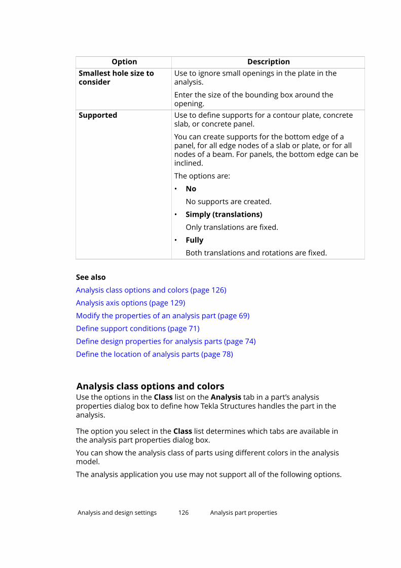
Option DescriptionSmallest hole size toconsider
Use to ignore small openings in the plate in theanalysis.
Enter the size of the bounding box around theopening.
Supported Use to define supports for a contour plate, concreteslab, or concrete panel.
You can create supports for the bottom edge of apanel, for all edge nodes of a slab or plate, or for allnodes of a beam. For panels, the bottom edge can beinclined.
The options are:
• No
No supports are created.
• Simply (translations)
Only translations are fixed.
• Fully
Both translations and rotations are fixed.
See also
Analysis class options and colors (page 126)
Analysis axis options (page 129)
Modify the properties of an analysis part (page 69)
Define support conditions (page 71)
Define design properties for analysis parts (page 74)
Define the location of analysis parts (page 78)
Analysis class options and colorsUse the options in the Class list on the Analysis tab in a part’s analysisproperties dialog box to define how Tekla Structures handles the part in theanalysis.
The option you select in the Class list determines which tabs are available inthe analysis part properties dialog box.
You can show the analysis class of parts using different colors in the analysismodel.
The analysis application you use may not support all of the following options.
Analysis and design settings 126 Analysis part properties

Option Description ColorBeam Line object of two nodes.
Part can take any load, including temperature.
Dark red
Beam - Truss Part can only take axial forces, not bending ortorsion moments, or shear forces. Usually used forbraces.
Green
Beam - Truss-Compressiononly
Part can only take compressive axial forces, notmoments or shear forces. If this part goes intotension, it is ignored in the analysis.
Yellow
Beam - Truss-Tension only
Part can only take tensile axial forces, notmoments or shear forces. If this part goes intocompression, it is ignored in the analysis.
Pink
Beam - Ignore Part ignored in the analysis.
Self-weight load is taken into account if you haveset Generate self weight load to Yes on theLoading tab.
Part notshown inthe model
Column Vertical line object of two nodes. Modeled frombottom to top.
Part can take any load, including temperature.
Dark red
Column - Truss Part can only take axial forces, not bending ortorsion moments, or shear forces. Usually used forbraces.
Green
Column - Truss-Compressiononly
Part can only take compressive axial forces, notmoments or shear forces. If this part goes intotension, it is ignored in the analysis.
Yellow
Column - Truss-Tension only
Part can only take tensile axial forces, notmoments or shear forces. If this part goes intocompression, it is ignored in the analysis.
Pink
Column - Ignore Part ignored in the analysis.
Self-weight load is taken into account if you haveset Generate self weight load to Yes on theLoading tab.
Part notshown inthe model
Secondary Line object of two nodes.
Part can take any load, including temperature.
For parts whose analysis class is Secondary, Keepaxis position is off by default. Secondary partssnap to nearest nodes instead of part end nodes.
Dark red
Secondary -Truss
Part can only take axial forces, not bending ortorsion moments, or shear forces. Usually used forbraces.
Green
Analysis and design settings 127 Analysis part properties

Option Description ColorSecondary -Truss-Compressiononly
Part can only take compressive axial forces, notmoments or shear forces. If this part goes intotension, it is ignored in the analysis.
Yellow
Secondary -Truss-Tensiononly
Part can only take tensile axial forces, notmoments or shear forces. If this part goes intocompression, it is ignored in the analysis.
Pink
Secondary -Ignore
Part ignored in the analysis.
Self-weight load is taken into account if you haveset Generate self weight load to Yes on theLoading tab.
Part notshown inthe model
Wall - Shell Part can take any load, except temperature. AquaWall - Plate Same as Wall - Shell but plate elements are used
in the analysis application.Aqua
Slab - Shell Part can take any load, except temperature. AquaSlab - Plate Same as Slab - Shell but plate, membrane, or mat
foundation elements are used in the analysisapplication.
AquaSlab -MembraneSlab - MatfoundationSlab - Rigiddiaphragm
Only applies to parts parallel to a global xy plane.
Filter: Nodes that belong to a part matching thefilter will be connected with rigid links whichtogether affect displacement. For example, you canuse column_filter to connect only column nodesto rigid diaphragms.
Lilac
Slab - Ignore Part is ignored in the analysis.
Self-weight load is taken into account if you haveset Generate self weight load to Yes on theLoading tab.
Part notshown inthe model
Contour plate -Shell
Part can take any load, except temperature. Aqua
Contour plate -Plate
Same as Contour plate - Shell but plate ormembrane elements are used in the analysisapplication.
Aqua
Contour plate -Membrane
Aqua
Contour plate -Rigiddiaphragm
Only applies to parts parallel to a global xy plane.
Filter: Nodes that belong to a part matching thefilter will be connected with rigid links whichtogether affect displacement. For example, you can
Lilac
Analysis and design settings 128 Analysis part properties

Option Description Coloruse column_filter to connect only column nodesto rigid diaphragms.
Contour plate -Ignore
Part ignored in the analysis.
Self-weight load is taken into account if you haveset Generate self weight load to Yes on theLoading tab.
Part notshown inthe model
See also
Show analysis class in model views (page 95)
Analysis part properties (page 116)
Analysis axis optionsUse the options in the Axis list on the Position tab in a part’s analysisproperties dialog box to define the location of the analysis part in relation tothe physical part.
Option Description Use forNeutral axis The neutral axis is the analysis axis
for this part. The location of theanalysis axis changes if the profile ofthe part changes.
Reference axis(eccentricity by neutralaxis)
The part reference line is the analysisaxis for this part. The location of theneutral axis defines the axiseccentricity.
Reference axis The part reference line is the analysisaxis for this part.
Top left The analysis axis is located in the topleft corner of the part.
Beam objects(beams,columns,braces)
Top center The analysis axis is located in the topcenter point of the part cross section.
Beam objects
Top right The analysis axis is located in the topright corner of the part.
Beam objects
Middle left The analysis axis is located in themiddle of the left side of the part.
Beam objects
Middle center The analysis axis is located in thecenter point of the part cross section.
Beam objects
Middle right The analysis axis is located in themiddle of the right side of the part.
Beam objects
Analysis and design settings 129 Analysis part properties

Option Description Use forBottom left The analysis axis is located in the
bottom left corner of the part.Beam objects
Bottom center The analysis axis is located in thebottom center point of the part crosssection.
Beam objects
Bottom right The analysis axis is located in thebottom right corner of the part.
Beam objects
Top plane The analysis axis is bound to the topplane.
Plate objects(plates, slabs,panels)
Middle plane The analysis axis is bound to themiddle plane.
Plate objects
Bottom plane The analysis axis is bound to thebottom plane.
Plate objects
Left plane The analysis axis is bound to the leftplane.
Plate objects
Right plane The analysis axis is bound to the rightplane.
Plate objects
Middle plane (of left/right)
The analysis axis is bound to themiddle plane of left/right.
Plate objects
Tekla Structures uses the options above for each part when you select Modeldefault from the Member axis location list in the Analysis Model Propertiesdialog box.
If you select Neutral axis, Tekla Structures takes the part location and endoffsets into account when it creates nodes. If you select either of theReference axis options, Tekla Structures creates nodes at part referencepoints.
See also
Analysis part properties (page 116)
Analysis model properties (page 110)
Analysis and design settings 130 Analysis node properties

10.6 Analysis node propertiesUse the Analysis node properties dialog box to view and modify theproperties of a node in an analysis model.
To access the dialog box, double-click an analysis node.
Option DescriptionSupports Defines which support conditions are used for the
node.
The options are:
• Get supports from part(s)
The support conditions of a corresponding partend are used for the node.
• User-defined node supports
You can define the support conditions for thenode.
If you select User-defined node supports, you canselect one of the following options:
These options automatically set the degrees offreedom for the node.
You can modify a predefined combination to suit yourneeds. If you do that, Tekla Structures indicates it withthis option:
Rotation If you selected User-defined node supports, you candefine the rotation of the node.
The options are:
• Not rotated
• Rotated
If you select Rotated, you can define the rotation, oryou can set the rotation by the current work plane byclicking Set rotation by current work plane.
Analysis and design settings 131 Analysis node properties

Option DescriptionUx
Uy
Uz
Rx
Ry
Rz
Define the translational (U) and rotational (R) degreesof freedom (displacements and rotations) of the nodein the global x, y, and z directions.
The options are:
• Free
• Fixed
• Spring
If you select Spring, enter the spring constant. Theunits depend on the settings in File menu --> Settings--> Options --> Units and decimals.
See also
Create an analysis node (page 63)
Merge analysis nodes (page 65)
Analysis model objects (page 9)
Analysis node colors (page 63)
10.7 Analysis rigid link propertiesUse the Analysis rigid link properties dialog box to view and modify the endconditions of a rigid link.
To access the dialog box, double-click a rigid link.
Option DescriptionReleases Defines which releases are used for a rigid link start or
end.
The options are:
• Automatic releases (by rules)
• User-defined releasesStart or End Defines which of the predefined or user-defined
combinations for releases is used for a rigid link startor end.
These are the predefined options:
Analysis and design settings 132 Analysis rigid link properties

Option DescriptionThese options automatically set the degrees offreedom.
You can modify a predefined combination to suit yourneeds. If you do that, Tekla Structures indicates it withthis option:
Ux
Uy
Uz
Define the translational degrees of freedom(displacements) in the global x, y, and z directions.
The options are:
• Free
• Fixed
• Spring
If you select Spring, enter the translational springconstant. The units depend on the settings in Filemenu --> Settings --> Options --> Units anddecimals.
Rx
Ry
Rz
Define the rotational degrees of freedom (rotations) inthe global x, y, and z directions.
The options are:
• Pinned
• Fixed
• Spring
• Partial release
If you select Spring, enter the rotational springconstant. The units depend on the settings in Filemenu --> Settings --> Options --> Units anddecimals.
Use Partial release to specify if the degree ofconnectivity is between fixed and pinned. Enter avalue between 0 (fixed) and 1 (pinned).
Local Y direction Defines the local y direction of the rigid link. Theoptions are the global x, y, and z directions.
The local x direction is always the direction of the rigidlink.
Analysis and design settings 133 Analysis rigid link properties

See also
Create a rigid link (page 64)
Analysis model objects (page 9)
10.8 Analysis bar position propertiesUse the Analysis Bar Position Properties dialog box to view and modify theposition of an analysis bar.
To access the dialog box, select an analysis bar, and then double-click a handleat an end of the analysis bar.
Option DescriptionOffset mode Defines whether the automatic (Automatic offset) or
user-defined (Manual offset) offset values are usedfor the analysis bar end.
Offset Defines the offset values in the global x, y, and zdirections.
See also
Define the location of analysis parts (page 78)
10.9 Analysis area position propertiesUse the Analysis Area Position Properties dialog box to view and modify theposition of an analysis area.
To access the dialog box, select an analysis area, and then double-click ahandle at an analysis area corner.
Option DescriptionOffset mode Defines whether the automatic (Automatic offset) or
user-defined (Manual offset) offset values are usedfor the analysis bar end.
Offset Defines the offset values in the global x, y, and zdirections.
See also
Define the location of analysis parts (page 78)
Analysis and design settings 134 Analysis bar position properties

10.10 Analysis area edge propertiesUse the Analysis Area Edge Properties dialog box to view and modify theposition and connectivity of an analysis area edge.
To access the dialog box, select an analysis area, and then double-click ahandle at the mid-point of an analysis area edge.
Option DescriptionOffset mode Defines whether the automatic (Automatic offset) or
user-defined (Manual offset) offset values are usedfor the analysis bar end.
Offset Defines the offset values in the global x, y, and zdirections.
Releases Defines which of the predefined or user-definedcombinations for releases is used for the analysis areaedge.
These are the predefined options:
These options automatically set the degrees offreedom.
You can modify a predefined combination to suit yourneeds. If you do that, Tekla Structures indicates it withthis option:
Ux
Uy
Uz
Define the translational degrees of freedom(displacements) in the global x, y, and z directions.
The options are:
• Free
• Fixed
• Spring
If you select Spring, enter the translational springconstant. The units depend on the settings in Filemenu --> Settings --> Options --> Units anddecimals.
Analysis and design settings 135 Analysis area edge properties

Option DescriptionRx
Ry
Rz
Define the rotational degrees of freedom (rotations) ofa member end in the global x, y, and z directions.
The options are:
• Pinned
• Fixed
• Spring
• Partial release
If you select Spring, enter the rotational springconstant. The units depend on the settings in Filemenu --> Settings --> Options --> Units anddecimals.
Use Partial release to specify if the degree ofconnectivity is between fixed and pinned. Enter avalue between 0 (fixed) and 1 (pinned).
See also
Define the location of analysis parts (page 78)
Analysis and design settings 136 Analysis area edge properties

11Disclaimer
© 2017 Trimble Solutions Corporation and its licensors. All rights reserved.
This Software Manual has been developed for use with the referencedSoftware. Use of the Software, and use of this Software Manual are governedby a License Agreement. Among other provisions, the License Agreement setscertain warranties for the Software and this Manual, disclaims otherwarranties, limits recoverable damages, defines permitted uses of theSoftware, and determines whether you are an authorized user of the Software.All information set forth in this manual is provided with the warranty set forthin the License Agreement. Please refer to the License Agreement for importantobligations and applicable limitations and restrictions on your rights. Trimbledoes not guarantee that the text is free of technical inaccuracies ortypographical errors. Trimble reserves the right to make changes andadditions to this manual due to changes in the software or otherwise.
In addition, this Software Manual is protected by copyright law and byinternational treaties. Unauthorized reproduction, display, modification, ordistribution of this Manual, or any portion of it, may result in severe civil andcriminal penalties, and will be prosecuted to the full extent permitted by law.
Tekla, Tekla Structures, Tekla BIMsight, BIMsight, Tekla Civil, Tedds, Solve,Fastrak and Orion are either registered trademarks or trademarks of TrimbleSolutions Corporation in the European Union, the United States, and/or othercountries. More about Trimble Solutions trademarks: http://www.tekla.com/tekla-trademarks. Trimble is a registered trademark or trademark of TrimbleInc. in the European Union, in the United States and/or other countries. Moreabout Trimble trademarks: http://www.trimble.com/trademarks.aspx. Otherproduct and company names mentioned in this Manual are or may betrademarks of their respective owners. By referring to a third-party product orbrand, Trimble does not intend to suggest an affiliation with or endorsementby such third party and disclaims any such affiliation or endorsement, exceptwhere otherwise expressly stated.
Portions of this software:
D-Cubed 2D DCM © 2010 Siemens Industry Software Limited. All rightsreserved.
Disclaimer 137 Analysis area edge properties
EPM toolkit © 1995-2006 Jotne EPM Technology a.s., Oslo, Norway. All rightsreserved.
Open Cascade Express Mesh © 2015 OPEN CASCADE S.A.S. All rights reserved.
PolyBoolean C++ Library © 2001-2012 Complex A5 Co. Ltd. All rights reserved.
FLY SDK - CAD SDK © 2012 VisualIntegrity™. All rights reserved.
Teigha © 2002-2016 Open Design Alliance. All rights reserved.
CADhatch.com © 2017. All rights reserved.
FlexNet Publisher © 2014 Flexera Software LLC. All rights reserved.
This product contains proprietary and confidential technology, informationand creative works owned by Flexera Software LLC and its licensors, if any. Anyuse, copying, publication, distribution, display, modification, or transmission ofsuch technology in whole or in part in any form or by any means without theprior express written permission of Flexera Software LLC is strictly prohibited.Except where expressly provided by Flexera Software LLC in writing,possession of this technology shall not be construed to confer any license orrights under any Flexera Software LLC intellectual property rights, whether byestoppel, implication, or otherwise.
To see the third party open source software licenses, go to Tekla Structures,click File menu --> Help --> About Tekla Structures and then click the 3rdparty licenses option.
The elements of the software described in this Manual are protected byseveral patents and possibly pending patent applications in the United Statesand/or other countries. For more information go to page http://www.tekla.com/tekla-patents.
Disclaimer 138 Analysis area edge properties

Index
Aadding
analysis model rules............................... 59objects to analysis model.......................62
analysis & design.............................................7analysis and design.........................................7
settings..................................................... 98workflow...................................................13
analysis and design applications.................12analysis and design models
working with............................................ 89analysis and design systems....................... 12analysis applications.....................................12
linking to Tekla Structures......................12merging models...................................... 91selecting for analysis model.................. 50
analysis areasedge properties..................................... 135position properties............................... 134
analysis axisof analysis models...................................56of parts................................................ 78,79options for parts................................... 129
analysis bars.................................................... 9position properties............................... 134showing numbers....................................95
analysis class.......................................... 95,126analysis members........................................... 9
showing numbers....................................95analysis model rules
adding.......................................................59creating.....................................................59
analysis models............................................... 7adding objects......................................... 62adding rules............................................. 59axis settings............................................. 56changing creation method.....................55checking objects...................................... 54copying..................................................... 66creating.......................................... 47,50,51
creating by copying................................. 66creating modal models...........................52creating rules........................................... 59creation method......................................49defining properties................................. 47deleting.....................................................67exporting.................................................. 90filtering objects........................................49including objects..................................... 48merging.................................................... 91modifying................................................. 54modifying properties.............................. 55objects........................................................ 9properties...............................................110removing objects.....................................62resetting editing...................................... 80resetting model merging........................91viewing results......................................... 96warnings...................................................89working with............................................ 89
analysis nodes................................................. 9colors........................................................ 63creating.....................................................63merging.................................................... 65properties...............................................130showing numbers....................................95
analysis parts...................................................9axis location........................................78,79copying..................................................... 81defining properties............................ 68,69deleting.....................................................82modifying................................................. 68modifying properties......................... 68,69offsets....................................................... 80position.....................................................78properties...............................................116resetting editing...................................... 80viewing properties...................................69
analysis resultssaving........................................................93saving as user-defined attributes..........94
139

viewing......................................................94analysis type................................................ 126applying loads to parts.................................33area loads.......................................................26
properties...............................................102attaching
loads to parts...........................................32axis settings
defining for analysis models..................56axis
of analysis parts...................................... 79
Bbounding box................................................ 33buckling length.............................................. 76
Kmode options........................................ 77
Ccheck design.................................................. 75checking
analysis models....................................... 54load groups.............................................. 42loads......................................................... 42
colorsby analysis type................................95,126by analysis utility check.......................... 96of analysis nodes.....................................63
combiningloads......................................................... 83
compatibility of load groups........................20copying
analysis models....................................... 66analysis parts........................................... 81load combinations.................................. 87
creatinganalysis model rules............................... 59analysis models.............................47,50,51analysis models by copying....................66analysis nodes......................................... 63area loads.................................................26line loads.................................................. 25load combinations............................. 84,85load groups.........................................15,18loads.................................................... 15,22modal analysis models........................... 52
point loads............................................... 25rigid links.................................................. 64strain.........................................................27temperature loads.................................. 27uniform loads.......................................... 26wind loads................................................ 28
creation methodchanging for analysis model.................. 55of analysis model.................................... 49
Ddefining
analysis model properties......................47analysis part properties.................... 68,69design properties of analysis models...59design properties of analysis parts.......74load groups.............................................. 18modal masses for analysis models.......58seismic loads for analysis models.........57
deletinganalysis models....................................... 67analysis parts........................................... 82load combinations.................................. 88load groups.............................................. 21
design propertiesdefining for analysis models..................59defining for analysis parts......................74
designomitting parts.......................................... 75
direct links......................................................12distances
of loads.....................................................35distributing loads.......................................... 32
Eeffective buckling length.............................. 76
Kmode options........................................ 77examples
creating wind loads.................................29exporting
analysis models....................................... 90load groups.............................................. 45
140

Ffiltering
analysis model objects........................... 49filters
in analysis models...................................49
Ggrouping
loads.................................................... 15,18
Hhandles
of loads.....................................................40
Iimporting
load groups.............................................. 46
KKmode options.............................................. 77
Lline loads........................................................ 25
properties...............................................101linking
Tekla Structures with analysisapplications..............................................12
load attachment............................................32load combination process............................83
using non-standard factors....................17load combination
factors.....................................................107properties...............................................107settings................................................... 107types....................................................... 108
load combinations........................................ 83copying..................................................... 87creating................................................84,85deleting.....................................................88
modifying................................................. 86saving for later use..................................87
load forms......................................................24load groups....................................................18
checking....................................................42compatibility............................................ 20creating................................................15,18defining.....................................................18deleting.....................................................21exporting.................................................. 45importing..................................................46modifying................................................. 18moving loads to another group.............44properties.................................................98setting current......................................... 19working with............................................ 41
load modeling code...................................... 16options................................................... 107
load modelingnon-standard combination factors....... 17
load models..................................................... 7load panel............................................... 36,105load types.......................................................15load-bearing parts........................................ 33loaded area....................................................35loaded length.................................................35loads
applying.................................................... 33attaching...................................................32bounding box...........................................33changing length or area......................... 35changing load group............................... 44checking....................................................42combining................................................ 83creating................................................15,22defining properties................................. 22distribution...............................................32forms........................................................ 24grouping..............................................15,18load panel properties........................... 105magnitude................................................23modal........................................................58modifying.......................................32,35,40modifying distribution............................ 36modifying location or layout..................38moving to another load group...............44properties...............................................100scaling in model views............................ 41
141

seismic...................................................... 57types......................................................... 15working with............................................ 41
Mmember axis location............................56,129merging
analysis models....................................... 91analysis nodes......................................... 65models using analysis applications.......91models using SAP2000........................... 91resetting................................................... 91
modal analysis...............................................58creating analysis models........................ 52
modal masses................................................58model merging.............................................. 91
resetting................................................... 91modifying
analysis model properties......................55analysis models....................................... 54analysis part properties.................... 68,69analysis parts........................................... 68load combinations.................................. 86load groups.............................................. 18load location or layout............................38loads......................................................... 32
movingload ends or corners...............................40
Nnodes, see analysis nodes........................... 63
Ooffsets
of analysis parts...................................... 80
Ppartial safety factors...................................107parts
analysis properties................................116physical models...............................................7point loads..................................................... 25
properties...............................................100position
of analysis parts...................................... 78properties
analysis models.....................................110analysis parts.........................................116load combination.................................. 107loads....................................................... 100
Rreduction factors.........................................107removing
objects from analysis model..................62reports
of loads.....................................................42resetting
editing of analysis parts......................... 80rigid diaphragms............................................. 9rigid links.......................................................... 9
creating.....................................................64properties...............................................132
SSAP2000
merging analysis models........................91saving
analysis results........................................ 93analysis results as user-definedattributes..................................................94load combinations.................................. 87
scalingloads in model views...............................41
seismic analysis.............................................57seismic loads................................................. 57seismic masses..............................................57setting
current load group.................................. 19load modeling code................................ 16
settingsanalysis and design properties..............98analysis area edge properties............. 135analysis area position properties........134analysis bar position properties..........134analysis model properties....................110analysis node properties......................130
142

analysis part properties....................... 116area load properties............................. 102line load properties...............................101load combination properties...............107load group properties.............................98load panel properties........................... 105load properties...................................... 100point load properties............................100rigid link properties...............................132temperature load properties...............103uniform load properties.......................102wind load properties.............................104
showinganalysis bar numbers............................. 95analysis member numbers.................... 95analysis node numbers.......................... 95
strain...............................................................27support conditions........................................71
defining for part ends.............................71defining for plates................................... 72symbols.................................................... 73
Ttemperature loads........................................ 27
properties...............................................103
Uuniform loads................................................ 26
properties...............................................102utilization ratio.............................................. 96
Vviewing
analysis results........................................ 94
Wwarnings
about analysis models............................89Wind Load Generator (28)...................... 28,29
properties...............................................104wind loads
creating.....................................................28
examples.................................................. 29properties...............................................104
workflowin analysis and design.............................13
143

144