risa revit link help - structural engineering...
TRANSCRIPT

RISA-Revit 2017 Link (v17.1)User's Manual
RISA Technologies, Inc.
26632 Towne Centre Drive, Suite 210
Foothill Ranch, California 92610
(949) 951-5815
(949) 951-5848 (FAX)
risa.com

Copyright 2016 by RISA Technologies, Inc All rights reserved. No portion of the contents ofthis publication may be reproduced or transmitted in any means without the express written
permission of RISA Technologies, Inc.
We have done our best to ensure that the material found in this publication is both useful andaccurate. However, please be aware that errors may exist in this publication. RISA Tech-
nologies, Inc makes no guarantees concerning accuracy of the information found here or in theuse to which it may be put.

Table of Contents
Table of Contents
General Reference Manual I
Introduction 1
How will using Revit and RISA togetherhelp me? 1
Installing the RISA-Revit Link 1
License Agreement 2
Version Information 4
Link Information 4
Compatibility Information 4
Workflow 5
Which Program Should I Start In? 5
Two-Way Integration (Round-Tripping) 6
Examples 7
What if Something Goes Wrong? 9
Getting Started 10
Export Revit Model to RISAFloor or RISA-3D 10
Import RISAFloor or RISA-3D model toRevit 15
RISA Parameters 21
Tagging Beams 25
Loading Tags 25
Procedure 25
Technical Support 29
Appendix A - Element Linking Details 30
Floors/Levels 30
Beams 30
Analytical Links 34
Braces 34
Columns 35
Walls 38
Footings 40
Foundation Slabs 41
Foundation Slab Pedestals 42
Grids 42
Decks/Diaphragms/Floor Slabs 42
Rebar 44
Materials 44
Boundary Conditions 44
Loads 44
Appendix B - Mapping Files 46
Shape Mapping 46
Material Mapping 47
RISAFloor Load Case Mapping 48

Introduction
IntroductionThe RISA-Revit Link is intended to provide a seamless and thorough transfer of data between RISA and Revit.This data transfer is constantly improving and evolving, and this version of the RISA-Revit Link represents anevolution of many previous versions of the Link. The level of integration between the two programs is made pos-sible by the Revit API, which provides a back door into Revit for RISA to communicate through. The close part-nership between RISA and Autodesk means that RISA developers have unrestricted access to the Revit API,resulting in the most seamless third-party Revit Link on the market.
How will using Revit and RISA together help me?The fundamental advantage of linking RISA and Revit together is that it helps you to avoid mistakes, and elim-inate redundancies (duplication of effort). Traditionally, structural models were created in RISA either fromscratch or based off of existing drawings. The model was solved, and then results were printed and used to manu-ally update drawings. Any simple oversight or typo could cause serious problems. A mistakenly entered beamsize on the drawings meant that an undersized beam would be erected, which could potentially fail. Furthermore,hours were wasted manually transcribing text from one program to another. Eventually RISA developed a DXFImport/Export process that eliminated some of these problems. DXF drawings could be imported to and exportedfrom RISA, but they could not 'update' existing drawings, so most of the drafting work on framing plans had towait until the structural engineer's analysis was complete. Any changes made to the structure during a projecthad to separately be made to both RISA and CAD drawings.
With BIM (Building Information Modeling) these limitations no longer exist. By creating a 3D model of smart 'ele-ments' (rather than just linework) it is possible to link large amounts of information between the drawings(Revit) and the analysis model (RISA). The concept of round-tripping is part of the standard BIM workflow,whereby changes and updates can be continuously shared between models. By utilizing the BIM workflow youcan ensure that your analysis model and drawings match each other, even after multiple revisions over the lifeof the project.
Installing the RISA-Revit LinkThe RISA-Revit Link works best when both RISA and Revit are installed on the same computer. This is not astrict requirement though. For this reason the installation instructions below present steps for both the Revitcomputer and the RISA computer. If both programs are present on one machine then ensure that all steps are fol-lowed for that machine:
Revit Computer
1. Ensure that Revit is installed, and that the version matches that shown on the Version Information page.2. Find the Autodesk Application Manager in the Windows Start Menu. Use that program to determine if
Revit updates are available. If Revit updates are listed as available then install them.3. Download the latest RISA-Revit Link from the RISA website: http://risa.com/partners/prt_revit.html4. Close Revit (if it is currently open) and run the installer. Once the installation is complete you are ready
to begin using the RISA-Revit Link.
General Reference Manual 1

RISA Computer (may be separate from Revit Computer)
1. Launch RISA-3D, and go to the Help menu. Click on 'Check for Update'. If an update is available then down-load and install it.
2. Repeat Step 1 for RISAFloor if applicable.3. Repeat Step 1 for RISAFoundation if applicable.
License AgreementEND-USER LICENSE AGREEMENT FOR
RISA TECHNOLOGIES, INC. SOFTWARE
The RISA-Revit Link software product (SOFTWARE PRODUCT) includes computer software, the associated media,any printed materials, and any electronic documentation. By installing, copying, accessing or otherwise using theSOFTWARE PRODUCT, you agree to be bound by the terms of this agreement. If you do not agree with the termsof this agreement RISA Technologies, Inc. is unwilling to license the SOFTWARE PRODUCT to you. In such eventyou must delete any installations and destroy any copies of the SOFTWARE PRODUCT and return the SOFTWAREPRODUCT to RISA Technologies, Inc. within 60 days of purchase for a full refund.2016by RISA Technologies, Inc.All rights reserved. The SOFTWARE PRODUCT is protected by United States copyright laws and various inter-national treaties. All rights not specifically granted under this agreement are reserved by RISA Technologies.“RISA” as applied to structural engineering software is a registered trademark of RISA Technologies, Inc.
1. SOFTWARE LICENSE.The SOFTWARE PRODUCT is licensed, not sold. All right, title and interest is andremains vested in RISA Technologies, Inc. You may not rent, lease, or lend the SOFTWARE PRODUCT. You are spe-cifically granted a license to the use of this program on no more than one CPU at any given time. The NetworkVersion of the SOFTWARE PRODUCT is licensed for simultaneous use on a certain maximum number of networkstations that varies on a per license basis. The Subscription Version of the SOFTWARE PRODUCT is licensed forsimultaneous use on a certain maximum number of CPU’s that varies on a per license basis. As part of thelicense to use the SOFTWARE PRODUCT, the program user acknowledges the reading, understanding and accept-ance of all terms of this agreement. The SOFTWARE PRODUCT may not be reviewed, compared or evaluated inany manner in any publication without expressed written consent of RISA Technologies, Inc. You may not dis-assemble, decompile, reverse engineer or modify in any way the SOFTWARE PRODUCT. If the SOFTWAREPRODUCT was purchased at a discounted price for educational purposes it may in no event be used for pro-fessional design purposes. The terms of this license agreement are binding in perpetuity.
2. DISCLAIMER.We intend that the information contained in the SOFTWARE PRODUCT be accurate and reliable,but it is entirely the responsibility of the program user to verify the accuracy and applicability of any resultsobtained from the SOFTWARE PRODUCT. The SOFTWARE PRODUCT is intended for use by professional engineersand architects who possess an understanding of structural mechanics. In no event will RISA Technologies, Inc. orits officers be liable to anyone for any damages, including any lost profits, lost savings or lost data. In no eventwill RISA Technologies, Inc. or its officers be liable for incidental, special, punitive or consequential damages orprofessional malpractice arising out of or in connection with the usage of the SOFTWARE PRODUCT, even if RISATechnologies, Inc. or its officers have been advised of or should be aware of the possibility of such damages. RISATechnologies, Inc’s entire liability shall be limited to the purchase price or subscription price of the SOFTWAREPRODUCT.
3. LIMITED WARRANTY.RISA Technologies, Inc. warrants that the SOFTWARE PRODUCT will operate but doesnot warrant that the SOFTWARE PRODUCT will operate error free or without interruption. RISA Technologies,Inc sole obligation and your exclusive remedy under this warranty will be to receive software support from RISA
2 RISA-Revit Link General Reference
Introduction
Introduction
Technologies, Inc via telephone, email or fax. RISA Technologies, Inc shall only be obligated to provide supportfor the most recent version of the SOFTWARE PRODUCT. If your version of the SOFTWARE PRODUCT is not themost recent version RISA Technologies, Inc shall have no obligation to provide support in any form. Except asstated above the SOFTWARE PRODUCT is provided without warranty, express or implied, including without lim-itation the implied warranties of merchantability and fitness for a particular purpose.
4. PROTECTION DEVICE.In the event the SOFTWARE PRODUCT requires the use of a PROTECTION DEVICE tooperate, you are specifically prohibited from attempting to bypass the functionality of the PROTECTION DEVICEby any means. A lost or stolen PROTECTION DEVICE will not be replaced by RISA Technologies, Inc.
5. SUBSCRIPTION SERVICE.In the event the SOFTWARE PRODUCT is accessed via a SUBSCRIPTION SERVICE,RISA Technologies, Inc shall make the SUBSCRIPTION SERVICE available for your use via an internet connectionfor the Term of the Subscription Agreement. At the end of the Term of the Subscription Agreement your right toaccess the SOFTWARE PRODUCT via the SUBSCRIPTION SERVICE will terminate unless the Subscription Agree-ment is renewed. RISA Technologies, Inc does not guarantee the SUBSCRIPTION SERVICE will be available error-free or uninterrupted. You acknowledge RISA Technologies, Inc does not control the transfer of information overthe internet and that the SUBSCRIPTION SERVICE may be subject to interruptions or delays beyond the controlof RISA Technologies, Inc. RISA Technologies, Inc is not responsible of any delivery failures or any other damagesresulting from any problems with the SUBSCRIPTION SERVICE.
6. TERMINATION.RISA Technologies, Inc may terminate your right to use the SOFTWARE PRODUCT if you fail tocomply with the terms and conditions of this agreement. In such event you must delete any installations and des-troy any copies of the SOFTWARE PRODUCT and promptly return the SOFTWARE PRODUCT to RISA Tech-nologies, Inc.
7. CHOICE OF LAW.By entering into this Agreement in accordance with Paragraph 1, above, you have agreed tothe exclusive jurisdiction of the State and Federal courts of Orange County, California, USA for resolution of anydispute you have relating to the SOFTWARE PRODUCT or related goods and services provided by RISA Tech-nologies, Inc. All disputes therefore shall be resolved in accordance with the laws of the State of California, USAand all parties to this Agreement expressly agree to exclusive jurisdiction of, and venue in, the courts in OrangeCounty, California, USA. No choice of law rules of any jurisdiction apply.
"RISA" as applied to structural engineering software is a trademark of RISA Technologies, Inc.
General Reference Manual 3

Version Information
Link InformationRISA-Revit 2017 Link (Version 17.1)
Compatibility InformationProduct Required VersionRevit 2017.1.1RISA–3D 15.0.1 (or Higher)RISAFloor 11.0.1 (or Higher)RISAFoundation 9.0.1 (or Higher)
The RISA-Revit Link is not compatible with Revit LT because Revit LT does not have an API to communicate withthird-party applications.
One of the following operating systems is required:
l Microsoft Windows 10l Microsoft Windows 8.1l Microsoft Windows 7 SP1
4 RISA-Revit Link General Reference
Version Information

Workflow
WorkflowThere are a variety of options for workflow between RISA and Revit. Before using the RISA-Revit Link it is bestto understand what these are, and how they can best be used for your project.
Which Program Should I Start In?The RISA-Revit Link encompasses four programs (RISA-3D, RISAFloor, RISAFoundation, and Revit). Each programhas its own purpose, but all four fully integrate for one complete building design. The reasons for starting ineach program are listed below:
Starting in RevitThis is the most common workflow. Remember that the goal of the Revit model is to represent the physicalmodel as accurately as possible, whereas the goal of the RISA model is to represent the analytical model asaccurately as possible. There are many circumstances where physical arrangements are better represented indifferent ways from each other.
A Revit model may have a very complex physical arrangement that can be greatly simplified for structural ana-lysis. By starting in Revit you can model these physical complexities, and assign an analytical arrangement forRISA to use. If you instead start in RISA, the link will create members in Revit, but it will create them with themost basic physical geometry, since it does not know your intentions for details.
Take the detail shown below for example. On the left is the Revit representation of a column and beam. On theright is the RISA representation. The connection details shown in Revit are necessary for construction drawings,however in RISA a simple 'fixed' connection is sufficient to give an accurate analysis.
A proficient Revit user can assemble a structure in Revit as fast as a proficient RISA user can assemble a struc-ture in RISA. Therefore, especially if the architect has already started a Revit model, it may be fastest to gen-erate a model first in Revit which uses the architect's model as a template.
Be aware that your Revit model must be in good condition prior to exporting to RISA. This means that the ana-lytical model especially should be thoroughly reviewed to ensure that all elements properly connect to eachother. A messy Revit model will create a messy RISA model full of instabilities.
General Reference Manual 5

Starting in RISAFloorThis is the second most common workflow. RISAFloor and Revit are very similar in their scope, in that they areboth designed around building-type structures which have floors, roofs, and gridlines. This is as opposed to indus-trial structures which do not fit this profile. Most users who start in RISAFloor do so for the following reasons:
1. There is no Revit model from the architect, or the structural analysis must be underway prior to its avail-ability.
2. Your proficiency in RISAFloor modeling exceeds that of Revit modeling, so you can create a building modelmuch faster by working within RISAFloor.
There are many users who prefer to start the model in RISAFloor, just be aware that after importing to Revit forthe first time your Revit model may need some massaging in order to be ready for construction documentation.
Any RISA-3D elements that are present in the RISAFloor model (from RISAFloor-3D integration) will auto-matically be transferred over to Revit.
Starting in RISA-3DIt is less common that RISA-3D and Revit would be linked together without also using RISAFloor. While RISA-3Ddoes link with Revit, it is not constrained by some of the limitations that both Revit and RISAFloor have withregards to structure type. Revit is a Building Information Modeling program, so some structures which RISA-3Dis well suited for (tanks, bridges, oil platforms, etc) do not fit Revit's mold of clearly defined floor levels andgrids. Since the creation of RISAFloor, and due to its complete integration with RISA-3D, it is rare that RISA-3D isused on its own for building modeling purposes.
Two-Way Integration (Round-Tripping)
Initial Linking Between RISA and Revit ElementsWhenever a RISA model is imported to Revit for the first time, or vice versa, a link is formed between the ele-ments. This link is maintained by the Exchange File, which handles all of the bookkeeping between the two mod-els. For this reason it is important to always use the same Exchange File when transferring back and forthmultiple times (round-tripping). Whenever an Exchange File is exported and "overwrites" a previous version ofthe exchange file, it is actually a "merge" of new data into the existing exchange file.
The exchange file maps RISA element ID's with Revit element ID's. For example, a beam in the RISA model withthe label M16 may be represented as a Revit beam with BIM ID #949. The Exchange File maintains a relationshipbetween M16 and BIM ID #949 in order to track changes and map them between the two programs.
Round Trips (Exporting Revit to RISA)Whenever a Revit model is exported to RISA, the Link performs a sophisticated comparison using theRevit model and the Exchange File to determine what has changed between the Revit model as it currentlyexists, and what was imported from RISA during the last RISA to Revit import. This optimizes the export processand prevents the Link from making unintended modifications to existing RISA elements, resulting in much fastertransfers if few changes were made within the Revit model.
Certain RISA properties are not mapped to Revit, such as unbraced lengths. These properties are not modified bythe RISA-Revit Link, so they will always remain as whatever they have been set to in RISA.
Round Trips (Importing RISA into Revit)Whenever a RISA model is imported to Revit, the Link performs a sophisticated comparison using the RISA modeland the Exchange File to determine what has changed between the RISA model as it currently exists, and what
6 RISA-Revit Link General Reference
Workflow
Workflow
was exported from Revit during the last Revit to RISA export. Certain element properties which are associatedwith a "solution" in RISA are always transferred into Revit regardless. These include:
l RISAFloor beam and column sizes (when members are set to be optimized)l Number of composite studsl Beam camberl Beam end reactions
With other element properties such as a beam's location or material, the Link performs a sophisticated com-parison using the RISA model and the Exchange File to determine what has changed between the RISA model asit currently exists, and what was exported to RISA during the last Revit to RISA export. This optimizes the importprocess and prevents the Link from making unintended modifications to existing Revit elements, resulting inmuch faster transfers if few changes were made within the RISA model.
Updating Member Sizes OnlyThe Import from RISA dialog box contains an option to update only the member sizes. This forces the Link toignore any changes to element geometry (such as the location of a beam or the slope of a roof).
The primary reason for using this option is when a discrepancy in geometry between both models ought to bemaintained. These circumstances have become rare since the analytical adjustment tools in Revit have beenimproved. However, there may be circumstances where it is necessary within a RISA model to create "DummyMembers" which should not be transferred to the Revit model, and this option will prevent those members frombeing imported into the Revit model.
ExamplesThe examples below can help illustrate typical workflow and Link behavior in a way that is easy to understand.
Example A (Model Originating in Revit)A typical workflow process can be easily understood from the example below:
1. An engineer exported his Revit model to RISAFloor, however the Link reported that some elements werenot transferred to RISA because the Revit model had errors in it.
2. Before working in RISAFloor, the engineer corrected problems with the Revit model, then exported toRISAFloor again, this time without any errors.
3. Loads were added to the RISA model, the model was solved, and the beams were sized. From within RISAa Revit Exchange File was exported, overwriting the existing Exchange File for that project (which wascreated upon the first successful export from Revit).
4. The Exchange File was imported back into Revit, completing the first round trip. Because the size of everymember in the model had changed, the import to Revit took several minutes.
General Reference Manual 7

Example B (Model Originating in RISA)A typical workflow process can be easily understood from the example below:
1. An engineer built a RISA model based on architectural drawings, as the architect is not using Revit.2. From within RISA a Revit Exchange File was exported.3. A new (blank) Revit model was created, and the Exchange File was imported using the RISA-Revit Link.
This populated the Revit model with all of the members, levels, gridlines, etc. Because the RISA modelwas large this import process took several minutes.
4. The engineer then cleaned up the Revit model so that the physical geometry of the elements wouldappear correctly on the construction drawings. This required changes such as moving beams downwardusing their z-direction offset so that their top flanges were all at the same elevation.
5. The Revit model was then exported back to RISA, therefore completing the first round-trip. Because theRISA-Revit Link ignores z-direction offsets the transfer back to RISA was fast, since no changes in theRevit model would impact the RISA model.
Example C (Subsequent Round Trips)The Link's behavior when dealing with changes to models is illustrated in the example below. Assume for thisexample that the model has already completed a successful roundtrip such as those illustrated in Example A orExample B, and that all of the members have been initially sized in both the RISA and Revit models:
1. The location of a shaft opening was moved in the Revit model. The location and spacing of the beams sur-rounding the shaft opening was changed accordingly (within the Revit model).
2. The model was then exported to RISAFloor. The RISAFloor Design Method was set to Analyze sizes fromRevit Model, ensuring that RISAFloor would merely check the already established member sizes ratherthan automatically resizing the members.
3. The model was solved in RISAFloor, and the engineer had to manually upsize several beams and columns.From within RISA a Revit Exchange File was exported, overwriting the existing Exchange File for that pro-ject.
4. Concurrently with Step 3, another engineer added a penthouse structure to the roof of the Revit model.This means that both the Revit and RISA model were being modified simultaneously, and were no longerin sync with each other.
5. The RISA Exchange File was imported into Revit. The import process was very quick, as only a few mem-bers (those that had been modified in RISA) were updated in the Revit model. The import process ignoredthe penthouse from Step 4, because the import only affects items that were modified in RISA.
6. Some columns were then moved in the RISA model, and some beams were upsized accordingly.7. The Revit model was then exported back to RISA so that the penthouse could be designed. The penthouse
came over, and the changes made in Step 6 were retained, since nothing relating to the columns had beenmodified in Revit.
8. The two models have been out of sync with each other since Step 4, which should be avoided wheneverpossible. At this point the column locations are inconsistent between the two models. In order to resyn-chronize the models so that they are once again identical the engineer exported the RISA model to Revit,at which point the columns were moved in the Revit model.
The link therefore supports concurrent work to be done on both models as described above, so long as the RISAuser and the Revit user are not working on the same element at the same time. If the penthouse addition in Step4 would have affected anything the columns from Step 6 then the Link would have changed the affected RISA ele-ments to match the Revit model (since the Revit model was being exported to RISA and not the other wayaround).
8 RISA-Revit Link General Reference
Workflow

Workflow
What if Something Goes Wrong?Occasionally a lack of communication between multiple people working on a given model can lead to unintendedmistakes. For this reason the RISA-Revit Link always creates a backup of the entire project (RISA and Revitfiles) immediately before any import or export operations. Whenever importing or exporting, save your Revitmodel first. Then, before any import or export operation is performed an ImportBackup or ExportBackup folderwill be created in the same location as your Revit model. This folder contains your entire project in the state itwas in immediately prior to importing/exporting. If anything goes wrong with your Revit or RISA models you candelete the current versions and retrieve the prior versions from the ImportBackup or ExportBackup folder,depending on whether you were importing to or exporting from Revit.
General Reference Manual 9

Getting StartedPrior to using the features of the RISA-Revit Link it is advisable to learn the proper workflow procedures out-lined in the previous chapter. Also, ensure that the link has been installed on the Revit computer.
Export Revit Model to RISAFloor or RISA-3D
Once the Revit model is ready to be exported to RISA, be sure to save the model .
Click on the Add-Ins tab, and then click on the Export to RISA button.
The Export dialog will appear as shown below:
10 RISA-Revit Link General Reference
Getting Started

Getting Started
Export to...Click on the logo of a RISA application in order to specify which one the Revit model should be exported to.
Note:
l RISAFloor models contain a RISA-3D model embedded within them. By exporting to RISAFloor you are alsoexporting RISA-3D information to the RISAFloor model. You can access this 3D-only information by usingthe Director tool within RISAFloor.
l Foundation data from the Revit model is always exported to the RISAFoundation model embedded in everyRISA-3D and/or RISAFloor model.
Export OptionsLaunch RISA Application exports an Exchange File to the specified destination, then launches the RISA applic-ation and automatically imports that Exchange File into the RISA application. This option is unavailable if RISA isnot installed on the Revit Computer. If this box is left unchecked then the Link exports an Exchange File to thespecified destination. To load the exchange file as a model in RISA go to File\Import\Autodesk Revit ExchangeFile.
Export only Selected objects exports only the elements currently selected in the Revit Model.
Coordinates specifies which Revit base point will be used to establish an origin (0,0,0) for coordinates in theRISA model. Either the "Project Base Point" or the "Survey Base Point" may be used to define the origin for allthree Global Axes in RISA. The Survey Base Point is typically used with the Shared Coordinates feature in Revit,which allows a common coordinate system to be used across multiple Revit models.
It is important to choose one of the two base points, and maintain the use of that base point throughout all trans-fers back and forth. To see the location of both points in the Revit Model look under the Architecture Filter Listin the Visibility/Graphic Overrides, under the Site category.
RISA X-Axis Alignment allows the export of Revit models to RISA using "True North" as the vertical plan dir-ection, as opposed to "Project North". Revit allows a discrepancy between True North as dictated by surveyingand "Project North" (Plan North) such that floor plans are not shown as skewed on drawings. If a structure isexported to RISA using True North then it is unlikely that the framing will align with RISA's Global Axes, whichmakes the generation of lateral loads difficult.
Revit Model to Export allows the export of either the Revit Physical or Revit Analytical model to be exported toRISAFloor. For RISA-3D only the Revit Analytical model may be exported.
RISAFloor Design Method is a RISAFloor specific option. In RISAFloor a Shape Group may be assigned to mem-bers (beams, columns, etc) from which the program will automatically choose an optimum size. An example of aShape Group would be "Wide Flange", as opposed to an explicit Shape such as "W24x55"
When "Optimize Member Sizes" is chosen the RISA-Revit Link will ignore the explicit member size specified inthe Revit model, and instead assign a corresponding shape group to the member in RISAFloor. This means thatthe member size in Revit will be ignored, and that RISAFloor will optimize the member size. Otherwise, if "Ana-lyze Sizes from Revit Model" is chosen then RISAFloor will perform analysis and code checks for the membersizes in Revit without optimization.
General Reference Manual 11

Elements to Link With RISAWalls specifies whether walls (and their openings) should be linked to the RISA model.
Boundary Conditions specifies whether boundary conditions should be linked to the RISA model.
Footings specifies whether Isolated Structural Foundations in Revit should be linked to RISA as Footing elementsin RISAFoundation. Because RISA requires a boundary condition at footing locations, boundary conditions mustalso be included.
Project Grids specifies whether Revit project grids should be linked to the RISA model.
Diaphragms specifies whether the Revit Floors should be linked to RISAFloor as Decks and Diaphragm Edges.
Loads specifies whether loads should be linked between the RISA and Revit models.
Load Combinations specifies whether load combinations should be linked between the RISA and Revit models.
Foundation Slabs specifies whether Structural Foundation Slab elements in the Revit model should be linked toMat Slab elements in RISAFoundation.
Elevated Slabs specifies whether Levels with the RISA Elevated Slab parameter turned on should be exported toRISAFloor as Concrete Slab Floors. A RISAFloor ES license is required in order to open a model exported withthis feature.
File NamesExchange File Name designates the name of the Exchange File that will be created by the Link. Browse to a tar-get folder in which this file will be created, or browse to an existing Exchange File that is to be updated.
The Exchange File acts an intermediary between RISA and Revit. It contains data that is not stored in either theRISA or Revit files. This data allows the link to keep track of both models to ensure that they are linked cor-rectly.
If you already have an Exchange File for the current project then be sure to specify that same file (as opposed tospecifying a new one). The new information will be merged into the existing Exchange File.
Base File Name designates the name of the base file (RISA model file) that will be created from the exchangefile. By default this will be given the same name and placed in the same location as the exchange file. Browse toa target folder in which this file will be created, or browse to an existing base file that is to be updated.
12 RISA-Revit Link General Reference
Getting Started

Getting Started
Advanced OptionsPrefix for RISA Labels specifies the prefix to applied to all RISA element names. For example, with the "REV_"prefix member M1 will be created in RISA with the name "REV_M1".
Merge Tolerance specifies a tolerance below which the RISA-Revit Link will automatically connect elements thatare very close to each other. This is especially useful in the case of beams that (accidentally) only nearly inter-sect in the Revit model.
Coordinate Precision controls the rounding off of joint coordinates during export. Using the 1/8" option elim-inates some issues that RISA's finite element mesher has with the extreme precision (1/256") that Revit uses.
The Export Process will Export only changed items by default. However you can override that behavior withthis setting and export all of the Revit elements to RISA, regardless of whether they were changed since the lastimport from RISA.
Reset Revit Structural Tolerances automatically adjusts the following tolerance values in the Revit model tothe indicated value. The default values in Revit are very large (6" to 12") which can cause problems with round-tripping with RISA, so the RISA-Revit Link resets these to 1" by default.
l Support Distancel Analytical-to-physical model distancel Analytical auto detect - Horizontall Analytical auto detect - Verticall Analytical Link auto detect
Export ProcessClick OK to begin the export process. A progress bar will be shown during this process.
Once the export process is complete a Report window will pop up which provides any error messages related tothe export, along with a summary of elements exported.
General Reference Manual 13

Errors will be grouped together by type. Use the +/- buttons to expand the trees and read each error. It is bestto correct problems with the Revit model which generate errors before moving forward with the RISA model.
If the Launch Program option was selected during export then the RISA program will automatically be launched.
If Write to File was selected then you must import the exchange file into RISA. Launch the relevantRISA program, and Import the Autodesk Revit Exchange File using the File Menu.
After importing the Exchange File, RISA automatically creates a corresponding base (model) file in the samefolder as the exchange file.
14 RISA-Revit Link General Reference
Getting Started

Getting Started
Import RISAFloor or RISA-3D model to RevitSave the latest changes (including results) in the RISAFloor or RISA-3D model, then Export an Exchange Fileusing the File Menu. If you already have an Exchange Eile for the current project then be sure to overwrite thatsame file (as opposed to creating a new one). Any changes will be merged into that file during the "overwrite"process.
If the exchange file was created successfully, an export confirmation dialog appears.
Note:
l The default Exchange File import/export directory can be set using the Tools > Application Settings menuof the RISA program.
Open Revit if it is not already open, and either open an existing model or create a new model into which theRISA model will be imported.
Once the Revit model is ready for RISA Import, be sure to save the model .
Be sure that the current (active) view in Revit is a 3D view.
Click on the Add-Ins tab, and then click on the Import from RISA button.
General Reference Manual 15

The Update From RISA dialog will appear:
Coordinates specifies which Revit base point will be used to establish a link to the origin (0,0,0) for coordinatesin the RISA model. Either the "Project Base Point" or the "Survey Base Point" may be used to define the originfor all three Global Axes in RISA. The Survey Base Point is typically used with the Shared Coordinates feature inRevit, which allows a common coordinate system to be used across multiple Revit models.
It is important to choose one of the two base points, and maintain the use of that base point throughout all trans-fers back and forth. To see the location of both points in the Revit Model look under the Architecture Filter Listin the Visibility/Graphic Overrides, under the Site category.
RISA X-Axis Alignment allows the import of RISA models to Revit using "True North" as the vertical plan dir-ection, as opposed to "Project North". Revit allows a discrepancy between True North as dictated by surveyingand "Project North" (Plan North) such that floor plans are not shown as skewed on drawings.
Import Process sets whether geometry changes should be brought in from the RISA model, or whether onlymember size changes should be brought over. The "Update Member Sizes Only" option should be used where adiscrepancy between the geometry of the RISA model and the Revit model ought to be maintained. See the Work-flow topic for more information on this option.
Revit Levels is only available to set when importing from RISA-3D. This allows the user to prevent new levelsfrom being created in the Revit model. When "Use Only Existing Levels" is selected all elements will be assigned
16 RISA-Revit Link General Reference
Getting Started

Getting Started
to the nearest existing Level in Revit. Otherwise the Link will create new levels in the Revit model for each elev-ation that RISA-3D elements exist.
General Reference Manual 17
Elements to Link With RISAWalls specifies whether walls (and their openings) should be linked to the RISA model.
Diaphragms specifies whether the Revit Floors should be linked to RISAFloor as Decks and Diaphragm Edges.
Boundary Conditions specifies whether boundary conditions should be linked to the RISA model.
Footings specifies whether Isolated Structural Foundations in Revit should be linked to RISA as Footing elementsin RISAFoundation. Because RISA requires a boundary condition at footing locations, boundary conditions mustalso be included.
Reactions specifies whether beam end reactions should be imported to the Revit model. An option exists to scalethe end reactions, or specify a minimum value which smaller reactions should be rounded up to.
Project Grids specifies whether Revit project grids should be linked to the RISA model.
Loads specifies whether loads should be linked between the RISA and Revit models.
Load Combinations specifies whether load combinations should be linked between the RISA and Revit models.
Foundation Slabs specifies whether Structural Foundation Slab elements in the Revit model should be linked toMat Slab elements in RISAFoundation.
Elevated Slabs specifies whether Concrete Slab Floors from the RISAFloor model should be imported to theRevit model.
Rebar may be imported into Revit as Rebar elements tied to concrete columns/footings/pedestals in Revit. Thisis currently only available for import to Revit, not export to RISA. RISA is seeking as much feedback as possibleon this new feature. Please provide any feedback that you have regarding this feature to RISA so that the futuredevelopment can proceed in a direction that makes this feature as useful as possible.
File NamesExchange File Name designates the name of the Exchange File that will be loaded by the Link. Browse to thefolder in which this file exits.
Base File Name designates the name of the base file (RISA model file) that is linked to the exchange file.
18 RISA-Revit Link General Reference
Getting Started

Getting Started
Advanced TabMerge Tolerance specifies a tolerance below which the RISA-Revit Link will automatically connect elements thatare very close to each other. This is especially useful in the case of beams that (accidentally) only nearly inter-sect in the Revit model.
The Import Process will Import only changed items by default. However you can override that behavior withthis setting and import all of the RISA elements to Revit, regardless of whether they were changed since the lastexport to RISA.
Beam Horizontal Projection is automatically detected by default. However, in models where beams are placedvery close to other elements (such as beams or walls) Revit automatically snaps the beam's analytical line toalign with the other element. Using the "Centerline" option effectively disables that auto-snapping feature, andmaintains correct analytical geometry. The "Centerline" option will set all beams to have a centerline horizontalprojection though, so any intentional horizontal projections within the Revit model will also be reset. This is typ-ically only used when troubleshooting an import where beams were incorrectly snapped to nearby elements.
Remove Link is useful for changing which Revit model your RISA model is linked to. Once a RISA model is linkedwith a Revit model, that RISA model cannot be then linked to a different Revit model without removing the linkto the first Revit model. In other words, a given RISA model may only be linked to one Revit model at a time.Check this box if your RISA model was previously linked to a different Revit model, and this is the first time youare importing it to this new Revit model.
The Correct Alignment option is only available when importing to a new (blank) Revit model. Revit has beenknown to incorrectly imports member geometries from certain RISA models (not RISA's fault) causing the align-ment of some members to be slightly off. This can result in members that were connected to each other in theRISA model to be unconnected in the Revit model. This option fixes those alignment issues, but is unchecked bydefault because it slows down the import process.
Reset Revit Structural Tolerances automatically adjusts the following tolerance values in the Revit model tothe indicated value. The default values in Revit are very large (6" to 12") which can cause problems with round-tripping with RISA, so the RISA-Revit Link resets these to 1" by default.
l Support Distancel Analytical-to-physical model distancel Analytical auto detect - Horizontall Analytical auto detect - Verticall Analytical Link auto detect
Shape Library Options allows you to specify which Revit libraries are used to load shapes when importing fromRISA. When the Link searches for a shape to be loaded into the Revit model it will look at these libraries insequential order.
The Imperial and Metric library paths are set in the Revit File Locations defaults. To modify where the Revitdefault libraries are go to the File Menu and choose Options/File Locations/Places
You can also specify a path to a custom library (by checking the Use Custom Library box), which the Link will useif it cannot find the shapes in the Revit libraries.
When using custom libraries you must browse to a folder which has subfolders titled Structural Columns andStructural Framing.Those folders must then have material-specific folder names, which contain the custom fam-ilies. This folder hierarchy matches the Revit default folder hierarchy.
Import ProcessClick OK to begin the import process. A progress bar will be shown during this process.
General Reference Manual 19

Once the import process is complete a Report window will pop up which provides any error messages related tothe export, along with a summary of elements added, modified, or deleted.
Errors will be grouped together by type. Use the +/- buttons to expand the trees and read each error. It is bestto correct problems with the RISA model which generate errors before moving forward with the Revit model.
After the import is complete a new view is created in the Revit model. It is a 3D view titled RISA Import Sum-mary. This view shows the entire model color coded, new elements colored green, modified elements colored yel-low, and unchanged elements colored black.
20 RISA-Revit Link General Reference
Getting Started

RISA Parameters
RISA ParametersIn order to make the mapping of element properties more complete, RISA has the capability to add parametersto Revit elements. These parameters do not exist by default in a Revit model which has been created fromscratch, but they can be enable (and disabled) with the RISA Parameters button:
The button icon shows the current status, whether the RISA Parameters are turned on or off. Below is a list ofall of the parameters that are created by the Link:
Composite (Yes/No)This parameter affects Analytical Beams. When it is enabled it maps to the "Composite" option on the Hot RolledTab of the Beams spreadsheet in RISAFloor, and controls whether the beams will be designed as composite mem-bers in RISAFloor. This parameter has no impact on RISA-3D.
Member/Wall LabelsFor beams, columns, braces, and walls both the Physical and Analytical Element has RISA member/wall labelinformation imported from RISA. This does not export back to RISA, and these labels are overwritten with eachimport from RISA.
General Reference Manual 21

Beam End ReactionsFor beams (Structural Framing) the Physical Element has RISA end reactions (shear and moment) imported fromRISA. This does not export back to RISA, and these reactions are overwritten with each import from RISA. The"Start" Reaction refers to the maximum shear at the i-end of the beam. The "End" Reaction refers to the max-imum shear at the j-end of the beam. The same convention also applies to end moments.
Wood Wall DesignFor wood walls the Physical Element has design information imported from RISA. This does not export back toRISA, and this information is overwritten with each import from RISA. Parameters are created for the sheathinggrade, sheathing thickness (including whether sheathing is one sided or on both sides of the wall), and the nail-ing required at the edge of each piece of sheathing.
22 RISA-Revit Link General Reference
RISA Parameters

RISA Parameters
RISA Structural FloorWhen exporting from Revit to RISAFloor this Level parameter controls whether the "Level" is brought intoRISAFloor as a "Floor". By unchecking this box for Levels which are irrelevant in RISAFloor (such as levels thatexist in the Revit model for architectural reasons only) the RISA model is greatly simplified.
RISA Elevated SlabThe state of this parameter (on/off) is ignored if "RISA Structural Floor" is unchecked. When this parameter isunchecked the Level will be exported to RISAFloor as a Beam Supported Floor. When the is parameter is checkedthe Level will be exported as a Concrete Slab Floor. You must have a RISAFloor ES license in order to use Con-crete Slab Floors.
General Reference Manual 23

RISA PedestalThis parameter is only used for concrete columns. It is used to differentiate between column members and ped-estal members. When specifying a concrete column as a RISA Pedestal it will be ignored by RISA-3D andRISAFloor, and will instead be brought over into RISAFoundation as a Pedestal.
RISA Drop PanelThis parameter allows RISA to remember which Floor Slab elements are Drop Panels versus Thickened Regionswhen round-tripping. Do not ever manually edit this parameter.
24 RISA-Revit Link General Reference
RISA Parameters

Tagging Beams
Tagging BeamsBeams within the Revit model contain parameters (member data such as beam size, camber, end reactions, etc)that can be displayed on framing plans. This information is automatically transferred from RISA models. TheRISA-Revit Link comes with several useful tags to display this information.
The directions below explain how to tag all of the beams in a framing plan at once. Specific tags may be omittedfrom this process if desired.
Loading TagsIf you have not already done so, load the RISA tags into your Revit model. To do so, click on the Insert tab, andclick on the Load Family button.
Navigate to the following folder:
Documents\Revit Link 2016\Beam Tags\
Note:
l If the Revit Link has been installed to a custom location such as C:\RISA then look for the Revit Link 2016folder under the C:\RISA folder.
Select all of the files in that folder and click the Open button. This will load the RISA tags into your Revit model.
ProcedureEnsure that the Revit model has had a RISA model imported, and that end reactions were also imported (if applic-able). The tagging process much be done for each framing plan separately, so open the first relevant framingplan.
Click on the Annotate tab within Revit, and then click on the "Beam Annotations" button:
The Beam Annotation Dialog will open. If the beams already have tags you may want to check the box "Removeexisting beam tags...", which will replace the existing tags with the new RISA tags. Choose between the "Levelbeams in plan" and "Sloped beams in plan" tabs as applicable.
General Reference Manual 25

The procedure for each tag is shown below:
Loading Tag #1
Click on the Load Tag button .
Choose the "Structural Framing Tag" radio button, then click in the "Type" dropdown and choose RISA Start Reac-tions.
26 RISA-Revit Link General Reference
Tagging Beams

Tagging Beams
Loading Tag #2Repeat the procedure for Tag #1, loading the Beam Size tag instead (or the RISA Label tag to get theRISA member name)
Loading Tag #3Repeat the procedure for Tag #1, loading the RISA End Reactions tag instead.
Loading Tag #4Repeat the procedure for Tag #1, loading the RISA Start Moments tag instead.
Loading Tag #5Repeat the procedure for Tag #1, loading the Studs and Camber tag instead.
Loading Tag #6Repeat the procedure for Tag #1, loading the RISA End Moments tag instead.
Applying TagsThe framing tags should now be shown as below:
General Reference Manual 27
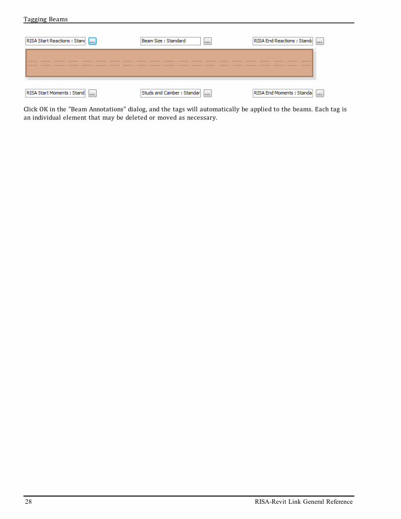
Click OK in the "Beam Annotations" dialog, and the tags will automatically be applied to the beams. Each tag isan individual element that may be deleted or moved as necessary.
28 RISA-Revit Link General Reference
Tagging Beams

Technical Support
Technical SupportTechnical support is an important part of the RISA-Revt Link. There is no charge for technical support for alllicensed owners of the current version of RISA-3D and/or RISAFloor. Technical support is very important to thestaff at RISA Technologies. We want our users to able to reach us when they are having difficulties with the Link.However, this service is not to be used as a way to avoid learning the program or learning how to perform struc-tural modeling in general.
Hours: 6am to 5pm Pacific Time, Monday through Friday
Before contacting technical support, please do the following:
1. Search the Help File or User's Manual. Most questions asked about the RISA-Revit Link are alreadyanswered there. Use the table of contents or index to find specific topics and appropriate sections. We goto great lengths to provide extensive written and online documentation for the link. We do this in order tohelp you understand the link and make it easier to use.
2. Open the Import from RISA or Export to RISA dialog in Revit. Go to the Advanced tab and click the Checkfor Updates button. If a newer version of the link is available, download and install it.
3. Within RISA-3D or RISAFloor click on the Help Menu and select Check for Updates. Occasionally there areknown issues which get corrected in periodic updates released by RISA.
4. Look at your analytical model in Revit to see if anything is wrong with it. Nine times out of ten the errorsthat occur during transfer are due to incorrect analytical models.
5. Take a few minutes to experiment with the problem to try to understand and solve it.
If none of the steps above correct your problem then contact support via e-mail for instructions on how to uploadyour files to the website. We will need those files to recreate the problem on our computers.
l If you encountered a problem importing from RISA to Revit, send us the entire contents of the auto-matically created ImportBackup folder.
l If you encountered a problem exporting from Revit to RISA, send us the entire contents of the auto-matically created ExportBackup folder.
E-Mail: [email protected]
This method is the only way to send us a model you would like help with. Make sure you tell us your name, com-pany name, RISA Key ID (go to Help\About), phone number, and give a decent problem description. Make sure tospecify which program you are integrating with, and whether you are using the "Export Selected Items Only"option.
Phone Support: (949) 951-5815
Feel free to call, especially if you need a quick answer and your question is not model specific and thereforedoesn’t require us to look at your file.
General Reference Manual 29

Appendix A - Element Linking DetailsThis appendix lists every type of element that is linked between RISA and Revit, and explains in detail the linkingthat is performed between RISA and Revit for that element type. If a given parameter from RISA or Revit is notlisted in this document then it is not linked between the two programs. In that case the RISA-Revit Link will notmodify that particular piece o f data. For example, the RISA-Revit Link does not impact unbraced lengths in RISA,or z-direction offsets in Revit.
Floors/LevelsFloors within RISAFloor are linked to Revit as Levels. Each Level within Revit has a RISA parameter called "RISAStructural Floor". This parameter is turned on by default for all Levels, but it can be disabled in order to preventthat level from being linked with RISAFloor. This is useful when there are many non-structural related levels ina Revit model, where the presence of those levels would only clutter up the RISAFloor model with extra floors.Structural elements assigned to a floor where the "RISA Structural Floor" parameter has been turned off will notbe linked to the RISAFloor model. This parameter is ignored when linking to RISA-3D.
An additional parameter called "RISA Elevated Slab" is also present. The state of this parameter (on/off) isignored if "RISA Structural Floor" is unchecked. When this parameter is unchecked the Level will be exported toRISAFloor as a Beam Supported Floor. When the is parameter is checked the Level will be exported as a Con-crete Slab Floor. You must have a RISAFloor ES license in order to use Concrete Slab Floors.
Note:
l The RISA Elevated Slab parameter is only available in Revit 2016 and newer.l Revit Level names may not exceed 32 characters when used with the RISA-Revit Link.l RISAFloor ES does not support non-concrete beams on Concrete Slab Floors. Therefore if theRISA Elevated Slab box is checked, any non-concrete beams on that Level will not be exported to RISA.
l RISAFloor Floors are mapped to Revit Levels on a one-to-one basis. Each RISAFloor Floor must have a cor-responding Revit Level, however there may be additional Revit Levels with the "RISA StructuralFloor" parameter turned off, RISAFloor will ignore those.
l When importing from RISA-3D to Revit new Revit Levels will be created as necessary unless the "Use onlyExisting Levels" option is selected.
BeamsBeams within RISAFloor and Members assigned to Member Type "Beam" in RISA-3D are both transferred toRevit as Structural Framing Beams. Revit Structural Framing Beams are transferred to RISAFloor as Beams, andto RISA-3D as Members assigned to Member Type "Beam".
ShapeThe Mapping File is used to match RISA Shape names with Revit Family Instance names. When exporting to RISA-3D or RISAFloor, if a matching shape name cannot be found in the mapping file then the beam is created as arectangular 1"x1" shape.
When importing from RISA-3D or RISAFloor into Revit, if a matching shape name cannot be found in the mappingfile then the shape is brought over using a random family instance (such as a W12x30). These members are colorcoded purple in the RISA Import Summary view, for easy identification.
A notification will be made in the warning log if a shape cannot be mapped.
RISAFloor members which are not assigned an explicit beam size are assigned to a Shape Group. The RISA-RevitLink does not transfer shape groups. Therefore the RISAFloor model must be solved, and the results must besaved in order to transfer the beam sizes chosen by RISAFloor during solution.
RISA-3D Members are assigned a Design List of "None" when transferred from Revit.
30 RISA-Revit Link General Reference
Appendix A - Element Linking Details

Appendix A - Element Linking Details
Reference LevelThis parameter is only used when linking the Revit Physical model to RISAFloor. When linking to RISAFloor, theReference Level parameter of the Revit beam is used to determine which floor the beam should exist on.
Level OffsetWhen linking to RISAFloor, the Start Level Offset and End Level Offset parameters of the Revit beam are used toassign Elevation Offsets in the RISAFloor model. The Elevation Offsets in RISAFloor are used to defined slopingbeams. Because RISAFloor only supports sloping at the top-most Floor, any beams assigned to Reference Levelother than the top-most Floor will be flattened during export (i.e. all Level Offsets are set to zero).
RISAFloor does not support negative Elevation Offsets, so the Level Offsets in Revit must always be positive val-ues. This means that the sloped roof "Level" in Revit should be at the base of the slope.
Cross-Section RotationThe Cross-Section Rotation parameter in Revit is used to set the "Orientation" parameter in the Beams spread-sheet in RISAFloor, and the Members spreadsheet in RISA-3D. Because RISAFloor only supports "Strong Axis" or"Weak Axis" orientation, RISAFloor will analyze the member with either a 0 degree or 90 degree orientation,depending on which angle the Revit rotation is closest to. This will not reset the orientation in Revit duringround-tripping, so it is safe to bring geometry back and forth for any rotation angle.
MaterialThe Revit Material is linked to the Material designated in the RISAFloor Beams spreadsheet or the RISA-3D Members spreadsheet. For more information on Material linking see the Materials topic.
Start/End (Moment) ConnectionsThe Start Connection and End Connection parameters in Revit are used to indicate Cantilevers in a RISAFloormodel. These parameters are ignored by RISA-3D. Below are guidelines for usage of these parameters:
l RISAFloor has two different types of cantilever members:1. Cantilever Beams are beams which are continuous over a support, and unsupported on at least one
end. In the example below, beams M1, M3, M5, and M6 are all cantilever beams. They are eithercontinuous passing over supporting member M2 (and Columns B1 and B2) or they are two membersthat have moment connections to each other at that support location. Either way the analysiswould be treated the same, so RISAFloor does not differentiate between these two possibilities.Cantilever beams always have a backspan.
General Reference Manual 31

2. Outriggers are beams which cantilever directly off of a column, and which have no backspan. There-fore the entire moment generated by the outrigger beam is carried by the column it is projectingfrom. In the example below, beams M10 and M11 are outriggers from columns A1 and A2 respect-ively. An outrigger must connect to a column at its supported end in RISAFloor. Outriggers may notbe supported by other beams, or by walls.
l A cantilever beam must be drawn as two members in Revit in order to transfer correctly into RISAFlooras a cantilever beam. Otherwise, modeling the beam as a single element in Revit will result in an instabil-ity in RISAFloor. Below is an example of how the cantilever beams in the above example import toRISAFloor. Note that each beam is modeled as two elements in Revit, with a Cantilever Moment con-nection on each beam.
l An outrigger may be drawn as one member in Revit. As long as the member attaches to a column, and hasa Cantilever Moment connection defined at that column, and no backspan beam is present that also has aCantilever Moment connection defined, then the outrigger will be correctly identified.
Structural UsageThe Structural Usage parameter in Revit is used to identify whether a beam is acting as a girder, joist, hori-zontal brace, etc. Most of the available designations in Revit are irrelevant to RISA. RISA exports all beams asstructural usage "Other" in Revit. The only relevant designation for the RISA-Revit link is "Horizontal Bracing".All beams in Revit that are designated with Structural Usage: Horizontal Bracing are imported as HorizontalBrace (HBrace) members to RISA. Because RISAFloor does not model horizontal bracing, an HBrace member isonly visible in the RISA-3D model embedded in RISAFloor.
32 RISA-Revit Link General Reference
Appendix A - Element Linking Details
Appendix A - Element Linking Details
Camber SizeThe camber size parameter in Revit is filled in by the camber values in the RISAFloor solution. This is a one waylink, which means that Camber Size is only transferred from RISA to Revit, not from Revit to RISA. This field isnot used when linking to RISA-3D.
Number of StudsThe Number of Studs parameter in Revit is filled in by the stud values in the RISAFloor solution. This is a oneway link, which means that studs are only transferred from RISA to Revit, not from Revit to RISA. This field isnot used when linking to RISA-3D, and it is not used for non-composite beams.
Enable Analytical ModelThis flag in Revit allows the user to designate a beam as non-analytical. Any element that does not have its Ana-lytical Model enabled is ignored by the RISA-Revit Link. Therefore this flag is a useful way to have the Linkignore miscellaneous framing members that are not intended for RISA analysis.
RISA ReactionsBeam end reactions are transferred to Revit from both RISA-3D and RISAFloor.
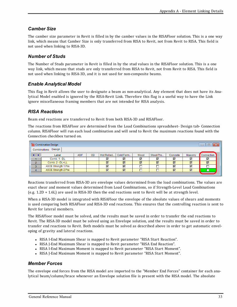
The reactions from RISAFloor are determined from the Load Combinations spreadsheet- Design tab- Connectioncolumn. RISAFloor will run each load combination and will send to Revit the maximum reactions found with theConnection checkbox turned on.
Reactions transferred from RISA-3D are envelope values determined from the load combinations. The values areexact shear and moment values determined from Load Combinations, so if Strength-Level Load Combinations(e.g. 1.2D + 1.6L) are used in RISA-3D then the end reactions sent to Revit will be at strength level.
When a RISA-3D model is integrated with RISAFloor the envelope of the absolute values of shears and momentsis used comparing both RISAFloor and RISA-3D end reactions. This ensures that the controlling reaction is sent toRevit for lateral members.
The RISAFloor model must be solved, and the results must be saved in order to transfer the end reactions toRevit. The RISA-3D model must be solved using an Envelope solution, and the results must be saved in order totransfer end reactions to Revit. Both models must be solved as described above in order to get automatic envel-oping of gravity and lateral reactions.
l RISA I-End Maximum Shear is mapped to Revit parameter "RISA Start Reaction".l RISA J-End Maximum Shear is mapped to Revit parameter "RISA End Reaction".l RISA I-End Maximum Moment is mapped to Revit parameter "RISA Start Moment".l RISA J-End Maximum Moment is mapped to Revit parameter "RISA Start Moment".
Member ForcesThe envelope end forces from the RISA model are imported to the "Member End Forces" container for each ana-lytical beam/column/brace whenever an Envelope solution file is present with the RISA model. The absolute
General Reference Manual 33

value maximum force is imported to Revit without a sign. In the case of lateral beams and columns the maximumforce between RISAFloor and RISA-3D is imported.
CompositeThis analytical parameter is a RISA parameter used to designate whether a steel beam should be designed ascomposite in RISAFloor. It is ignored for non-steel beams, and for RISA-3D. This setting links to the compositeflag in the RISAFloor Beams spreadsheet, on the Hot Rolled tab.
RISABeam LabelThe RISABeam Label parameter in Revit is a RISA parameter which is filled in by the member label from theRISA model. This is a one way link, which means that RISA beam label is only transferred from RISA to Revit, notfrom Revit to RISA.
Analyze AsThis analytical parameter is used to designate which members are part of the lateral force resisting systemversus the members which are intended to support gravity loads only. This maps to the "Function" parameter inthe Beams spreadsheet in RISAFloor, and in the Members spreadsheet, Hot Rolled tab in RISA-3D. Members des-ignated as Lateral will appear in both RISAFloor and the RISA-3D model embedded under RISAFloor. Membersdesignated as Gravity will appear only in RISAFloor, and not in the RISA-3D model embedded under RISAFloor.
End ReleasesThis analytical parameter is linked to the end releases in RISAFloor and RISA-3D. RISAFloor only supports"Pinned" or "Fixed" end releases. If the end releases of a Revit Beam do not correspond with standard Pinned orFixed releases then the link chooses the closest match when transferring to RISAFloor. The Revit end releases inthis circumstance are not affected when transferring back to Revit.
Curved BeamsCurved beams in Revit are split into multiple straight-line segment members in RISA-3D. The member size,material, and other parameters from the first segment are then linked back to the entire curved beam in Revit.It is important to set the unbraced lengths correctly in RISA-3D, so that each segment uses the full length of thebeam as its unbraced length if appropriate. Leaving the unbraced lengths blank in RISA-3D will result in the pro-gram assuming brace points between each segment.
Curved beams may not be exported to RISAFloor.
Analytical LinksAnalytical links in Revit are linked to Rigid Links in RISA-3D, regardless of whether the analytical link was auto-matically generated in Revit or whether it was manually drawn. Rigid Links that are drawn in RISA-3D are notbrought into Revit as analytical links though. The analytical link must originate in Revit, at which point it canround-trip to RISA mapped as a rigid link. Analtyical links in Revit are ignored by RISAFloor.
BracesBraces assigned to Member Type "VBrace" in RISA-3D are transferred to Revit as Structural Framing Braces.Revit Structural Framing Braces are transferred to RISA-3D as Members assigned to Member Type "VBrace".Because RISAFloor does not model horizontal bracing, a VBrace member is only visible in the RISA-3D modelembedded in RISAFloor.
34 RISA-Revit Link General Reference
Appendix A - Element Linking Details

Appendix A - Element Linking Details
ShapeThe Mapping File is used to match RISA Shape names with Revit Family Instance names. When exporting to RISA-3D or RISAFloor, if a matching shape name cannot be found in the mapping file then the beam is created as arectangular 1"x1" shape.
When importing from RISA-3D or RISAFloor into Revit, if a matching shape name cannot be found in the mappingfile then the shape is brought over using a random family instance (such as a W12x30). These members are colorcoded purple in the RISA Import Summary view, for easy identification.
A notification will be made in the warning log if a shape cannot be mapped.
Cross-Section RotationThe Cross-Section Rotation parameter in Revit is linked to the "x-axis Rotation" parameter in the Membersspreadsheet in RISA-3D.
MaterialThe Revit Material is linked to the Material designated in the RISA-3D Members spreadsheet. For more inform-ation on Material linking see the Materials topic.
Enable Analytical ModelThis flag in Revit allows the user to designate a brace as non-analytical. Any element that does not have its Ana-lytical Model enabled is ignored by the RISA-Revit Link. Therefore this flag is a useful way to have the Linkignore miscellaneous framing members that are not intended for RISA analysis.
RISABrace LabelThe RISABrace Label parameter in Revit is a RISA parameter which is filled in by the member label from theRISA model. This is a one way link, which means that RISA brace label is only transferred from RISA to Revit, notfrom Revit to RISA.
Analyze AsThis analytical parameter is used to designate which members are part of the lateral force resisting systemversus the members which are intended to support gravity loads only. Braces are always part of the lateralforce resisting system, so they are always designated as "Lateral" in Revit and they therefore always createdwith function type "Lateral" in the Hot Rolled tab of the RISA-3D Members spreadsheet.
End ReleasesThis analytical parameter is linked to the end releases in RISA-3D, as defined in the Members spreadsheet,Advanced tab.
ColumnsColumns within RISAFloor and Members assigned to Member Type "Column" in RISA-3D are both transferred toRevit as Structural Columns. Revit Structural Columns are transferred to RISAFloor as Columns, and to RISA-3Das Members assigned to Member Type "Column".
ShapeThe Mapping File is used to match RISA Shape names with Revit Family Instance names. When exporting to RISA-3D or RISAFloor, if a matching shape name cannot be found in the mapping file then the beam is created as a
General Reference Manual 35

rectangular 1"x1" shape.
When importing from RISA-3D or RISAFloor into Revit, if a matching shape name cannot be found in the mappingfile then the shape is brought over using a random family instance (such as a W12x30). These members are colorcoded purple in the RISA Import Summary view, for easy identification.
A notification will be made in the warning log if a shape cannot be mapped.
RISAFloor members which are not assigned an explicit beam size are assigned to a Shape Group. The RISA-RevitLink does not transfer shape groups. Therefore the RISAFloor model must be solved, and the results must besaved in order to transfer the beam sizes chosen by RISAFloor during solution.
RISA-3D Members are assigned a Design List of "None" when transferred from Revit.
MaterialThe Revit Material is linked to the Material designated in the RISA-3D Members spreadsheet. For more inform-ation on Material linking see the Materials topic.
Base Level/OffsetThese parameters are only used when linking the Revit Physical model to RISAFloor. When linking to RISAFloor,the Base Level parameter of the Revit column is used to determine the base of the structure. The Base Levelshould not include structural framing, and there should be no structural framing below the Base Level other thanfoundation elements. The Base Offset is then used to set the "Splice Distance Below" parameter in the RISAFloorColumns spreadsheet.
For columns not terminating at the "base" of the structure, the Base Level sets the bottom-most Floor wherethat column exists. See the example below where the middle column terminates at a transfer beam. The BaseLevel for this column should be the Reference Level for the transfer beam.
36 RISA-Revit Link General Reference
Appendix A - Element Linking Details

Appendix A - Element Linking Details
These Parameters are not used when linking to RISA-3D.
Top Level/OffsetThese parameters are only used when linking the Revit Physical model to RISAFloor. When linking to RISAFloor,the Top Level parameter of the Revit column is used to set the top-most floor where the column exists. The TopOffset is then used to set the Elevation point for sloping members (along with the member End Offsets). Neg-ative values of Top Offset are not allowed, and are rounded to zero during export to RISA. Positive values of TopOffset are only allowed on the top-most floor, and will be rounded to zero during export if the Top Level is notthe top-most structural Level.
These Parameters are not used when linking to RISA-3D.
SplicesThere are three different hierarchies of columns in RISAFloor:
l Column: Defines the column from Floor-to-Floor.l Lift: Defines the physical column, as it would be cut by the fabricator. Spans at least one floor, terminatesat splices.
l Stack: Defines all Lifts that share the same horizontal coordinates.
For a single story structure there would only be one Lift per Stack because there are no splices. However, for asix story structure there may be two or three lifts per column stack, depending on how many splices arepresent.
General Reference Manual 37

Columns in Revit should be modeled to match Column Lifts. That is, each column element in the Revit modelshould be the same length as the physical piece that will be fabricated. The RISA-Revit Link automaticallyincludes column splices in between Column Elements that are stacked in the Revit model. The splice type isdetermined by the Top Connection parameter of the lower column. Specifying a Shear Connection or MomentConnection for the Top Connection of the lower column at the splice results in RISAFloor using a Shear orMoment connection at that location. Specifying "None" for a top connection results in RISAFloor using the Defaultsplice type, as defined in the Floors spreadsheet.
Enable Analytical ModelThis flag in Revit allows the user to designate a brace as non-analytical. Any element that does not have its Ana-lytical Model enabled is ignored by the RISA-Revit Link. Therefore this flag is a useful way to have the Linkignore miscellaneous framing members that are not intended for RISA analysis.
RISAColumn LabelThe RISAColumn Label parameter in Revit is a RISA parameter which is filled in by the member label from theRISA model. This is a one way link, which means that RISA column label is only transferred from RISA to Revit,not from Revit to RISA.
RISA PedestalThis parameter is only used for concrete columns. It is used to differentiate between column members and ped-estal members. When specifying a concrete column as a RISA Pedestal it will be ignored by RISA-3D andRISAFloor, and will instead be brought over into RISAFoundation as a Pedestal.
Analyze AsThis analytical parameter is used to designate which members are part of the lateral force resisting systemversus the members which are intended to support gravity loads only. This maps to the "Function" parameter inthe Columns spreadsheet in RISAFloor, and in the Members spreadsheet, Hot Rolled tab in RISA-3D. Members des-ignated as Lateral will appear in both RISAFloor and the RISA-3D model embedded under RISAFloor. Membersdesignated as Gravity will appear only in RISAFloor, and not in the RISA-3D model embedded under RISAFloor.
Note:
l Gravity Columns from Revit are automatically created as Lateral in RISA-3D and RISAFloor if they share anode with any lateral elements.
End ReleasesThese analytical parameters are linked to the end releases in RISA-3D, in the Members spreadsheet, Advancedtab. These parameters are not used when linking to RISAFloor.
WallsWall Panel elements in RISAFloor and RISA-3D are linked to Revit as Walls.
Structure/AssemblyEach Wall Type in Revit has a "Structure" assembly which defines the makeup of the wall. Only the layer that ismarked as the "Structural Material" is linked to RISA. The Material determines the wall type (Wood, Masonry,Concrete) and the thickness determines the wall thickness (or stud thickness for wood walls). This information islinked to the Wall Panels spreadsheet in RISAFloor and RISA-3D, specifically the "Material Type" and"Thickness" fields.
38 RISA-Revit Link General Reference
Appendix A - Element Linking Details

Appendix A - Element Linking Details
OpeningsWall openings may be modeled in Revit as "Wall Openings", "Door" Elements, "Window" Elements, or by Editingthe Profile of the wall. All of these opening types are linked to RISA as openings in the wall panel. Openingswhich are Excluded from the Analytical Model in Revit (accessible through the Analytical Adjust mode) areignored by the Link. Openings which violate the limitations of wall openings in RISA are not transferred to theRISA model, such as door openings at the corner of a wall (resulting in an L-shaped wall). Only rectangular open-ings are supported.
GeometryRISA-3D only supports rectangular walls. RISAFloor supports rectangular walls, and walls with a monoslope ontop only if the top of the wall is at the top-most level of the building. Walls which do not meet the limitations ofRISA are either flattened on top, modified to be rectangular based on the smallest possible bounding rectangle,or not brought over at all. The link provides a warning whenever the wall is modified during transfer to RISA,due to RISA limitations.
Embedded ColumnsRISAFloor does not support embedded columns within walls. Therefore, walls in Revit that have embeddedcolumns are split into multiple walls in RISA, with each wall butting up against the column. The Link keeps trackof these split walls, and brings them back as a single wall element during round trips to Revit. In the case of wallparameters not matching (e.g. different wall thicknesses) the properties from one of the two walls fromRISA will be assigned to the single wall in Revit.
Note:
l Do not rename the split walls in RISA. Otherwise the Link will no longer be able to recombine them to thesingle wall in Revit, since the Link uses the wall name to keep track of the splitting/recombining.
Base Constraint/OffsetThese parameters are only used when linking the Revit Physical model to RISAFloor. When linking to RISAFloor,the Base Constraint parameter of the Revit Wall is used to determine the base of the structure. The Base Levelshould not include structural framing, and there should be no structural framing below the Base Level other thanfoundation elements. The Base Constraint is then used to set the "Distance Below" parameter in the RISAFloorWall Panels spreadsheet.
For walls not terminating at the "base" of the structure, the Base Constraint sets the bottom-most Floor wherethat wall exists. This sets the "Bottom Floor" parameter in the RISAFloor Wall Panels spreadsheet. See theColumns topic for more information.
These Parameters are not used when linking to RISA-3D.
General Reference Manual 39

Top ConstraintThis parameter is only used when linking the Revit Physical model to RISAFloor. When linking to RISAFloor, theTop Constraint parameter of the Revit column is used to set the top-most floor where the column exists. Thissets the "Top Floor" parameter in the RISAFloor Wall Panels spreadsheet.
These Parameters are not used when linking to RISA-3D.
Wall StacksFor masonry and concrete walls, with consistent thickness, material, reinforcing, etc over their entire height itis best to define a single wall spanning multiple stories, as opposed to wood walls where it is best to define aseparate wall at each story, with the walls stacking atop each other. The RISA-Revit Link also supports the"Stacked Wall" element in Revit. The stacked wall is split into multiple elements when transferring into RISA,similar to the behavior of Embedded Columns (see above). Each wall in RISA that was split from the StackedWall in Revit links its information back to Revit for the specific location in the stacked wall.
Enable Analytical ModelThis flag in Revit allows the user to designate a wall as non-analytical. Any element that does not have its Ana-lytical Model enabled is ignored by the RISA-Revit Link. Therefore this flag is a useful way to have the Linkignore walls that are not intended for RISA analysis, such as partition walls.
Wood Wall DesignFor wood walls the Physical Wall Element has design information imported from RISA. This does not export backto RISA, and this information is overwritten with each import from RISA. Parameters are created for the sheath-ing grade, sheathing thickness (including whether sheathing is one sided or on both sides of the wall), and thenailing required at the edge of each piece of sheathing.
Analyze AsThis analytical parameter is used to designate which walls are part of the lateral force resisting system (shearwalls) versus the walls which are intended to support gravity loads only (bearing walls). This maps to the "Func-tion" parameter in the Wall Panels spreadsheet in RISAFloor. Walls designated as "Lateral" or "Gravity and Lat-eral" will appear in both RISAFloor and the RISA-3D model embedded under RISAFloor. Walls designated as"Gravity" will appear only in RISAFloor, and not in the RISA-3D model embedded under RISAFloor. This para-meter is not used when linking only to RISA-3D.
RISAWall LabelThe RISAWall Label parameter in Revit is a RISA parameter which is filled in by the wall label from theRISA model. This is a one way link, which means that RISA wall label is only transferred from RISA to Revit, notfrom Revit to RISA.
FootingsFootings within RISAFoundation (embedded under RISAFloor or RISA-3D) are linked to Revit as Isolated Struc-tural Foundations. To import footings from RISAFoundation into Revit there must be a solution file saved withthe RISAFoundation model. Only rectangular footings are supported.
DimensionsThe dimensions of a Revit Footing are imported to RISAFoundation as the "Footing Definition". RISAFoundation isintended to optimize footing sizes by providing a user input with a Min and Max Length, Width, and Thickness.
40 RISA-Revit Link General Reference
Appendix A - Element Linking Details

Appendix A - Element Linking Details
When exporting from Revit to RISAFoundation, each footing is assigned a Footing Definition where the Min andMax values for each dimension are set to the same value, effectively turning off the optimization. When import-ing from RISAFoundation into Revit the footing size is determined from the RISAFoundation solution, and newfamily types are created to match those dimensions.
MaterialThe Revit Material is linked to the Material designated in the RISAFoundation Footing Definitions spreadsheet.For more information on Material linking see the Materials topic.
Enable Analytical ModelThis flag in Revit allows the user to designate a footing as non-analytical. Any element that does not have itsAnalytical Model enabled is ignored by the RISA-Revit Link. Therefore this flag is a useful way to have the Linkignore footings that are not intended for RISA analysis.
Footing Pedestalsin Revit, concrete columns that have the "RISA Pedestal" analytical parameter turned on, and which sit atop Isol-ated Structural Foundations, are treated as Pedestals. This means that they are linked to RISAFoundation as thefooting pedestal. These columns are not imported to RISA-3D or RISAFloor as columns. The dimensions of thefooting pedestal are linked to the pedestal dimensions in the Footing Definitions spreadsheet of RISAFoundation.
Note:
l Footings that are not attached to a column are imported to Revit at the lowest Level in the Revit model.l Footings that are attached to a column are imported to Revit at the bottom of that column.l Footings are not allowed to overlap in plan, even if one is above or below another.
Foundation SlabsMat Slabs within RISAFoundation (embedded under RISAFloor or RISA-3D) are linked to Revit as Structural Found-ation Slabs. RISA does not have an elevation parameter for foundation slabs, so they are always imported toRevit at the lowest Level in the Revit model. Their elevation in the Revit model is not altered during round-trip-ping, so you may set the elevation for each slab correctly in Revit and it will remain there.
Slab OpeningsSlab openings in Revit may be represented by drawing internal loops using the "Edit Profile" tool in Revit. If theopening has any curves the curve will be broken up into straight-line segments approximating the curve whenexporting to RISAFoundation.
Thickened RegionsIn RISAFoundation, thickened regions may be defined within slabs. Because a given foundation slab must be of uni-form thickness in Revit, when importing to Revit the Link creates an additional slab underneath the main slab, torepresent the thickened portion. The fact that this additional slab is actually a thickened part of the main slab isthen remembered during round-tripping.
Structure/AssemblyEach Foundation Slab in Revit has a "Structure" assembly which defines the makeup of the slab. Only the layerthat is marked as the "Structural Material" is linked to RISA. The Material determines the concrete propertiesand the thickness determines the thickness of the slab (linked to the Material and Thickness parameters in theRISAFoundation Slabs spreadsheet).
General Reference Manual 41

Enable Analytical ModelThis flag in Revit allows the user to designate a foundation slab as non-analytical. Any element that does nothave its Analytical Model enabled is ignored by the RISA-Revit Link. Therefore this flag is a useful way to havethe Link ignore foundation slabs that are not intended for RISA analysis.
Foundation Slab Pedestalsin Revit, concrete columns that have the "RISA Pedestal" analytical parameter turned on, and which do not sitabove Footings, are treated as Pedestals. This means that they are linked to RISAFoundation as the foundationslab pedestal. These columns are not imported to RISA-3D or RISAFloor as columns. The dimensions of the found-ation pedestal are linked to the pedestal dimensions in the Pedestals spreadsheet of RISAFoundation.
Note:
l Unless all columns terminate at the same elevation and all pedestals are the same height, all FoundationSlabs and Pedestals are imported 20 feet below the bottom-most Revit Level during their first import toRevit. This is because RISAFoundation does not contain elevation data for foundation elements. You cancorrect the elevation in Revit and your changes will remain through subsequent round trips of those ele-ments.
GridsProject Girds within RISAFloor and RISA-3D are linked to Revit as Grids. RISA does not have an elevation para-meter for grids, so they are always imported to Revit at elevation 0'-0".
Decks/Diaphragms/Floor SlabsRevit Floor elements are linked to RISAFloor as explicitly defined Decks. The contiguous perimeter of a RevitFloor or group of Floors is linked to RISAFloor as the Diaphragm Edge. Revit Floors are not linked to RISA-3D.
Elevated SlabsOn Revit Levels that have the "RISA Elevated Slab" parameter turned on, the Floor element in Revit is linked asa Slab in RISAFloor ES
Note:
l In RISAFloor ES, thickened regions may be defined within slabs. Because a given Floor must be of uniformthickness in Revit, when importing to Revit the Link creates an additional floor slab underneath the mainfloor slab, to represent the thickened portion. The fact that this additional slab is actually a thickenedpart of the main slab is then remembered during round-tripping.
l Drop Panels in RISAFloor ES are imported to Revit using the geometry of the Column Strip from RISAFloorES. Since this is not always accurate for construction, you may edit the profile of the Drop Panel elementthat is imported to Revit and its geometry will be remembered during round trips. Drop Panel geometryother than Thickness is never exported to RISAFloor ES.
42 RISA-Revit Link General Reference
Appendix A - Element Linking Details
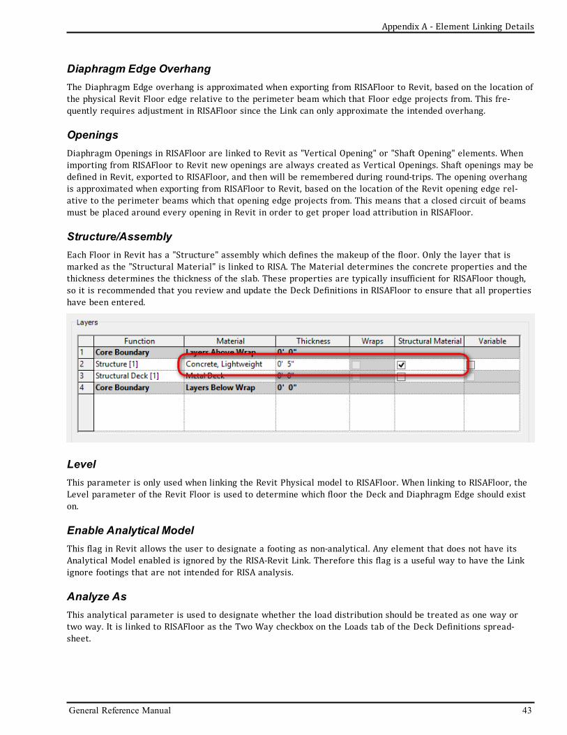
Appendix A - Element Linking Details
Diaphragm Edge OverhangThe Diaphragm Edge overhang is approximated when exporting from RISAFloor to Revit, based on the location ofthe physical Revit Floor edge relative to the perimeter beam which that Floor edge projects from. This fre-quently requires adjustment in RISAFloor since the Link can only approximate the intended overhang.
OpeningsDiaphragm Openings in RISAFloor are linked to Revit as "Vertical Opening" or "Shaft Opening" elements. Whenimporting from RISAFloor to Revit new openings are always created as Vertical Openings. Shaft openings may bedefined in Revit, exported to RISAFloor, and then will be remembered during round-trips. The opening overhangis approximated when exporting from RISAFloor to Revit, based on the location of the Revit opening edge rel-ative to the perimeter beams which that opening edge projects from. This means that a closed circuit of beamsmust be placed around every opening in Revit in order to get proper load attribution in RISAFloor.
Structure/AssemblyEach Floor in Revit has a "Structure" assembly which defines the makeup of the floor. Only the layer that ismarked as the "Structural Material" is linked to RISA. The Material determines the concrete properties and thethickness determines the thickness of the slab. These properties are typically insufficient for RISAFloor though,so it is recommended that you review and update the Deck Definitions in RISAFloor to ensure that all propertieshave been entered.
LevelThis parameter is only used when linking the Revit Physical model to RISAFloor. When linking to RISAFloor, theLevel parameter of the Revit Floor is used to determine which floor the Deck and Diaphragm Edge should existon.
Enable Analytical ModelThis flag in Revit allows the user to designate a footing as non-analytical. Any element that does not have itsAnalytical Model enabled is ignored by the RISA-Revit Link. Therefore this flag is a useful way to have the Linkignore footings that are not intended for RISA analysis.
Analyze AsThis analytical parameter is used to designate whether the load distribution should be treated as one way ortwo way. It is linked to RISAFloor as the Two Way checkbox on the Loads tab of the Deck Definitions spread-sheet.
General Reference Manual 43

RebarThe link currently has the ability to export rebar from RISA to Revit for concrete columns, foundation slab ped-estals, footings, and footing pedestals. The rebar exporting capabilities will be expanded in upcoming versions,and eventually two way transfer will be possible. The rebar in Revit is overwritten during each export from RISAif the rebar design in RISA changed since the last import to Revit.
RISA is seeking as much feedback as possible on this new feature. Please provide any feedback that you haveregarding this feature to RISA so that the future development can proceed in a direction that makes this featureas useful as possible.
Note:
l When linking to RISAFloor it is important to go back to RISAFloor after solving in RISA-3D and solve onemore time in RISAFloor so that the rebar design is consistent between the RISAFloor solution and theRISA-3D solution. Otherwise the rebar exported to Revit will only match one of the solutions in RISA(since the RISA solutions would have two different designs).
l A RISAFoundation saved solution is required in order to import Footing and Pedestal rebar to Revit.l Only equally spaced rebar in footings may be imported to Revit. Footings with banded rebar have theirrebar ignored for import.
MaterialsMaterials in Revit are linked to materials in RISA. The Mapping File is used for transferring materials betweenRISA and Revit. The following material types are supported:
l Hot Rolled Steell Cold Formed Steell Concretel Woodl Generall Aluminuml Masonry
Many material parameters that RISA needs for analysis and design are either incorrect, or not present in thedefault Revit libraries. Therefore it is recommended that all material properties be reviewed and updated in theRISA Materials spreadsheet after exporting to RISA.
Note:
l Currently wood species information is not linked between RISA and Revit. Revit creates a default woodmaterial when exporting to RISA, and RISA creates a default wood material when importing to Revit. Thematerial is not updated or affected during round trips.
Boundary ConditionsBoundary conditions assigned to Joints in RISA-3D are linked to Revit as Boundary Conditions. Translations, rota-tions, and spring stiffnesses are supported. Pinned boundary conditions are automatically applied to the bottomof column stacks transferred to RISA-3D regardless of whether the Boundary Condtions box was checked in theExport dialog. to prevent instabilities.
LoadsNote:
44 RISA-Revit Link General Reference
Appendix A - Element Linking Details

Appendix A - Element Linking Details
l Only loads applied in Global Directions are supported. All others are ignored.
Point LoadsPoint and Joint loads defined within RISA-3D and RISAFloor are transferred to Revit as Point Loads. Point Loadsin Revit are transferred to RISA-3D and RISAFloor as Point or Joint loads, depending on whether the load falls ona member or a joint.
Line LoadsDistributed Loads defined within RISA-3D and RISAFloor are transferred to Revit as Line Loads. Line Loads inRevit are transferred to RISA-3D and RISAFloor as distributed loads.
Note:
l Revit Line Loads which span multiple members will be broken down into multiple distributed loads whentransferred to RISA-3D.
Area LoadsArea Loads defined in RISA-3D and RISAFloor are transferred to Revit as Area Loads. Area Loads defined in Revitare transferred to RISA-3D and RISAFloor as Area Loads.
Note:
l Revit Area Loads which are defined by more than 4-points are ignored by the Link when transferring toRISA-3D.
l Each Revit Area Load is given its own Area Load definition within RISAFloor. Identical area loads arelumped into one Definition.
l Revit only allows one load case per load. Therefore when importing RISAFloor into Revit, only one loadmagnitude will be transferred from a given Area Load Definition. The load chosen will be the firstencountered in the following order: LL, DL, OL1, etc..
Load Cases/CategoriesLoad Cases and Categories are mapped between RISA and Revit using the Mapping File.
Load CombinationsThe transfer of Load Combinations between RISA and Revit is limited due to inherent differences in how the pro-grams handle them.
Note:
l The "State" flag within Revit maps to the "Service" flag within RISA-3Dl The "Type" flag within Revit maps to the "Solve" flag within RISA-3Dl RISA-3D only supports load combination nesting up to one level deep. Any further nesting will be ignoredby the Link.
General Reference Manual 45

Appendix B - Mapping FilesThe mapping file may be opened in Microsoft Excel. It can be found the following folder:
Docuemnts\Revit Link 2016\
Note:
l If the Revit Link has been installed to a custom location such as C:\RISA then look for the Revit Link 2016folder under the C:\RISA folder.
RISA and Revit use different terminologies for Shape Names, Material Names, and Load Categories. These ter-minologies are linked to each other by a process of "Mapping". Mapping is done using a Mapping file designed tobe customized per your standards.
Mapping does not need to be done for shapes which share the same name in both RISA and Revit. For example, aW8x10 is called "W8x10" in both programs, so it is omitted from the mapping file, but still transfers. A L3x3x3/16is called "L3x3x3" in RISA, so it must be mapped and is included in the mapping file.
The Excel based XML mapping file “RISA_Revit_Mapping_File.xml” is installed to the RISA-Revit Link folder. TheLink uses the mapping file during transfers between RISA and Revit. The file consists of three tabs: Shapes,Materials, and RF Load Cases.
Shape MappingThe Shapes tab consists of three columns: “RISA ShapeName”, “REVIT ShapeName”, and “ShapeType”. There aremany shapes already mapped in the file that is installed. Additional shapes may be added, and existing shapesmay be changed.
The Link looks for shape names from this tab of the spreadsheet. If they are not found, it looks for shape namesthat are identical between RISA and Revit, and maps them automatically.
For automatic concrete shape mapping the general conventions must be followed for naming in Revit. Forexample, rectangular concrete shapes must be named in the format 'a x b' and circular shapes must be named inthe format ' c" '. a, b, and c are the width, depth and diameter respectively. It is important to note that Revitstores rectangular concrete shape names as ‘width x depth’ whereas RISA stores these names as ‘depth x width’.This behavior is being accounted for by the Link.
The following ‘Shape Types’ should be used in the Shape Mapping File.
Hot RolledWF_SHAPE Wide Flange
TUBE_SHAPE TubePIPE_SHAPE Pipe
CHANNEL_SHAPE ChannelWT_SHAPE WTDBL_L_SHAPE Double LSNGL_L_SHAPE Single LRECT_SHAPE RectangularBAR_SHAPE BarTAP_WF_SHAPE Tapered Wide Flange
WoodNDS_SHAPE Rectangular
NDS_ROUND_SHAPE Round
46 RISA-Revit Link General Reference
Appendix B - Mapping Files

Appendix B - Mapping Files
ConcreteCRECT_SHAPE RectangularCRND_SHAPE RoundCL_SHAPE L ShapeCT_SHAPE T Shape
JoistsKJOIST_SHAPE K JoistLHJOIST_SHAPE LH JoistDLHJOIST_SHAPE DLH JoistSLHJOIST_SHAPE SLH JoistKCSJOIST_SHAPE KCS Joist
JOISTGIRDER_SHAPE Joist GirderWOOD_JOIST_SHAPE Wood Joist
AluminumAL_WF_SHAPE Wide FlangeAL_Z_SHAPE Zee ShapeAL_T_SHAPE Tee ShapeAL_PL_SHAPE Solid RectangleAL_L_SHAPE Single AngleAL_CS_SHAPE Cee Shape
AL_ROUNDTUBE_SHAPE Round TubeAL_RECTTUBE_SHAPE Rectangular TubeCold-Formed Steel
CU_SHAPE Cee ShapeCS_SHAPE Cee with LipsZU_SHAPE Zee ShapeZS_SHAPE Zee with LipsHU_SHAPE Hat Shape
Material MappingThe Materials tab consists of three columns: “RISA MaterialName”, “REVIT MaterialName”, and “MaterialType”.There are many materials already mapped in the file that is installed. Additional materials may be added, andexisting shapes may be changed.
Revit to RISAIf the mapping for a particular Revit material exists in the Mapping File, it is mapped over the RISA materialname mentioned on the spreadsheet. The material properties are preserved in RISA, and are not overwritten.
If a material match is not found in the mapping file, the Revit material name is sent to RISA. Material propertiesare created based on Revit material properties during the initial transfer, and are not overwritten thereafterregardless of changes made to the RISA material properties.
RISA to RevitIf the mapping for a particular RISA material exists in the Mapping File, it is mapped over the Revit materialname mentioned on the spreadsheet. The material properties in Revit are updated to the RISA material
General Reference Manual 47
properties.
If a material match is not found in the mapping file, the RISA material name is sent to Revit. Material propertiesare created based on RISA material properties during the initial transfer.
Available Material Types in RISACONCRETE_MATL Concrete Material (Family Instances)
HOT_ROLLED_STEEL_MATL Steel Material (Family Instances)NDS_WOOD_MATL Wood Material (Family Instances)GENERAL_MATL General Material (WallTypes)
Note:
l The RISA Material Name may not exceed 19 characters in length.l No two RISA materials should be mapped to the same Revit material.l No two Revit materials should be mapped to the same RISA material.l Material property changes should be made in both RISA and Revit simultaneously for consistency.
RISAFloor Load Case MappingThis RF Load Cases tab consists of three columns: “RISA LoadCaseName”, “REVIT LoadCaseName” and“LoadCaseType”. There are many load cases already mapped in the file that is installed. Additional load casesmay be added, and existing shapes may be changed.
RISAFloor is limited to a set of predefined Load Cases (Categories). For this reason, new Revit Load Cases cannotbe created in a RISAFloor model, so the Revit Load Cases must be mapped to the RISAFloor ones.
Revit to RISAThe Load Case of every load that is transferred from Revit to RISA is mapped using the mapping file. If no map-ping for a given Revit Load Case is present then the load will be transferred to RISAFloor under the OL4 cat-egory. RISA-3D does not have this limitation, so it will create new Load Cases using the Revit names.
The “LoadCaseType” is used to distinguish whether the load should be applied to the RISAFloor model, or to theRISA-3D model embedded within RISAFloor.
RISA to RevitThe Load Case of every load that is transferred from RISA to Revit is mapped using the mapping file. If no map-ping for a given RISA Load Case is present then a new Load Case will be created in Revit using the RISA LoadCase name.
Available Load Cases in RISAFloorDL PreComp Pre Composite Dead LoadDL PostComp Post Composite Dead LoadLL- Non Live LoadLL-Reduce Reducible Live LoadLLS - Non Live Load SpecialLLS-Reduce Reducible Live Load SpecialRLL- Non Roof Live LoadRLL-Reduce Reducible Roof Live LoadSL Snow LoadSLN Non Shedding Snow LoadRL Rain Load
48 RISA-Revit Link General Reference
Appendix B - Mapping Files

Appendix B - Mapping Files
OL1 Other Load 1OL2 Other Load 2OL3 Other Load 3OL4 Other Load 4Dyn Mass Dynamic MassVLL Vibration Load
Note:
l RISA Load Case names may not exceed 11 characters in length.
General Reference Manual 49


Index
Index
General Reference Manual i
A
Analyze As 34-35, 38, 40, 43
Annotate 25
Assembly 38, 41, 43
B
Base File Name 12, 18
Beam Annotations 25
Beam Size 27
Beams 30
Boundary Conditions 12, 18, 44
Braces 34
C
Camber 33
Cantilevers 31
Column Base 36
Column Splices 37
Column Top 37
Columns 35
Composite 34
Coordinate Precision 13
Coordinate System 11, 16
Correct Alignment 19
Cross-Section Rotation 31, 35
Curved Beams 34
D
Data Exchange 30
Decks 42
Diaphragms 12, 18, 42
E
Elevated Slabs 12, 18
Enable Analytical 33, 35, 38, 40-43
End Releases 34-35, 38
Exchange File Name 12, 18
Export Only Selected Objects 11
Export Options 11
Export Process 13
Exporting 10
F
File Names 12, 18
Floors 30
Footing Pedestals 41
Footings 12, 18, 40
Foundation Slabs 12, 18
G
Getting Started 10
Grids 42
H
Horizontal Projection 19
I
Import Process 16, 19
Importing 15
Install 1
L
Launch RISA Application 11
Level Offset 31

Index
ii RISA-Revit Link General Reference
Levels 30
Linked Elements 12, 18
Load Combinations 12, 18
Loads 12, 18, 44
M
Mapping Files 46
Material 31, 35-36, 41
Materials 44
Member Forces 33
Merge Tolerance 13, 19
N
Number of Studs 33
O
Openings 39
Orient to True North 11, 16
P
Pedestal 38
Pedestals 42
Phone Support 29
Prefix 13
Project Grids 12, 18
R
Reactions 18
Rebar 18, 44
Reference Level 31
Remove Link 19
Revit Levels 16
RISA End Moments 27
RISA End Reactions 27
RISA Parameters 21
RISA Reactions 33
RISA Start Moments 27
RISABeam Label 34
RISABrace Label 35
RISAColumn Label 38
RISAFloor Design Method 11
RISAWall Label 40
Round-Tripping 6
S
Shape Library Options 19
Structural Framing Tag 26
Structural Usage 32
Studs and Camber 27
Support E-Mail 29
T
Tagging Beams 25
Technical Support 29
Tolerances 13, 19
V
Version 4
W
Wall Base 39
Wall Stacks 40
Wall Top 40
Walls 12, 18, 38
Website 1
Wood Wall Design 40
Workflow 5