rigid pavement design 20-7-09.ppt
TRANSCRIPT
Design of Rigid PavementAs the name implies, rigid pavements
are rigid i.e, they do not flex much under loading like flexible pavements. They are constructed using cement concrete. In this case, the load carrying capacity is mainly due to the rigidity ad high modulus of elasticity of the slab (slab action). H. M. Westergaard is considered the pioneer in providing the rational treatment of the rigid pavement analysis.
1
Modulus of sub-grade reaction Westergaard considered the rigid pavement
slab as a thin elastic plate resting on soil sub-grade, which is assumed as a dense liquid. The upward reaction is assumed to be proportional to the deflection. Based on this assumption, Westergaard defined a modulus of sub-grade reaction in kg/cm3 given by where is the displacement level taken as 0.125 cm and is the pressure sustained by the rigid plate of 75 cm diameter at a deflection of 0.125 cm.
2
WHAT WE LOOK FOR IN A GOOD PAVEMENT
• Good Riding Quality
• Adequate Structural Capacity to withstand loads
• Good anti-skid properties
• Withstand ravages of weather (temperature/rainfall)
• Hard wearing surface
• Long life
• Low maintenance
• Economical not only in Initial Cost but over Life Cycle.
3
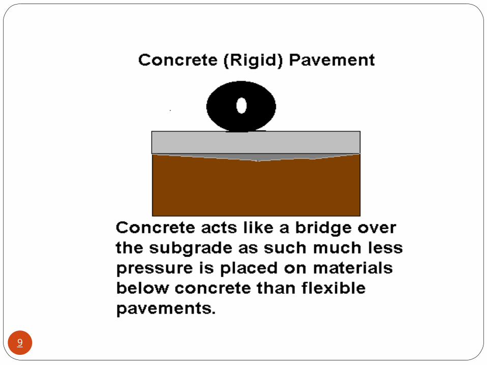
The rigid pavement has the slab action and is capable of transmitting the wheel load stresses through a wider area below. The main difference in structural behaviour of rigid pavement as compared to flexible pavement is that the critical condition of stress in the rigid pavement is the maximum flexural stress occurring in the slab due to wheel load and the temperature changes where as in the flexural pavement it is the distribution of compressive stresses.
4
As the rigid pavement has tensile strength, tensile stresses are developed due to the bending of the slab under wheel load and temperature variations. The rigid pavement does not get deformed to the shape of the lower surface as it can bridge the minor variations of lower layer.
5
The cement concrete slab can serve as a wearing surface as well an effective base course. The rigid pavements are designed using the elastic theory, assuming it as an elastic plate resting on an elastic foundation.
6
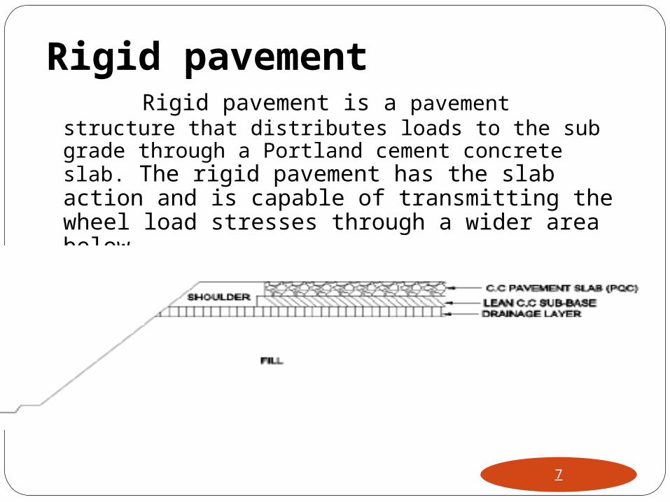
Rigid pavement Rigid pavement is a pavement structure
that distributes loads to the sub grade through a Portland cement concrete slab. The rigid pavement has the slab action and is capable of transmitting the wheel load stresses through a wider area below.
7
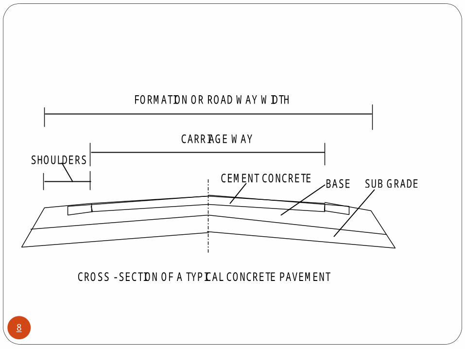
FORMATION OR ROAD WAY WIDTH
CARRIAGE WAY
SHOULDERS
CEMENT CONCRETE BASE SUB GRADE
CROSS - SECTION OF A TYPICAL CONCRETE PAVEMENT
8
9
ADVANTAGES OF CONCRETE PAVEMENTS
• Long Life (30-40 years)
• Practically Maintenance-Free
• Good Riding Quality
• Good Reflectivity
• Impenetrability to Water
• Can be Designed for Heavy Loading
• Fuel Savings @ 14% as per CRRI Study
• Favourable Life Cycle Cost
• Consumes less Quantity of Aggregates
• Can utilise Waste Material like Flyash10
CONCRETE ROAD - LOCATIONS CHOICE
• On poor sub-grade soil
• Heavy rain fall areas/water logged areas
• High Traffic volume
• Aggregates are expensive
• Cement available in close proximity
• Easy availability of fly ash and slag
Which helps in cost reduction and better quality
durable roads11
STRESSES IN CEMENT CONCRETE PAVEMENT
12
Cement concrete pavements represents the group of rigid pavements. Here the load carrying capacity is mainly due to the rigidity and high modulus of elasticity of the slab itself i.e., slab action. H.M Westergaard is considered the pioneer in providing the rational treatment to the problem of rigid pavement analysis.
13
Cement concrete pavements are relatively thin slabs laid directly over soil subgrade or over sub base course. The subbase of rigid pavement structure consists of one or more compacted layers of granular or stabilized material placed between the subgrade and the rigid slab for the following purposes:
14
To provide uniform, stable, and permanent support,
To increase the modulus of subgrade reaction(k)
To prevent pumping of fine-grained soils at joints, cracks ,and edges of the rigid slab, and
To provide working platform for construction equipment.
15
Stresses are caused in a Cement Concrete
pavement (CC) pavements due to wheel loads, daily and seasonal variation in temperature, changes in moisture content and other factors. For the design of CC pavement the stresses are calculated for each trial thickness and the process is repeated until the maximum resultant stress is within acceptable limit with respect to the flexure strength.
16
The determination of stresses in rigid pavement is based on analysis of Westergaard. Westergaard worked out stress equations when a wheel load is applied at three critical locations (Interior, edge and corner regions of CC slab). The stresses due to a single wheel load with circular contact were considered.
17
Design Principle
Warping stresses are introduced in CC pavement slab due to temperature variations between top and bottom of the slab during 24 hours of the day.
Variations in temperature during different seasons of the causes expansion and contraction of the CC pavement and frictional stresses are developed at the bottom of the slab. However the magnitude of frictional stresses is much low and is neglected.
18
The principle that is followed in the design of CC pavement is to determine the maximum values of Warping and load stresses for an assumed trial thickness of the pavement.
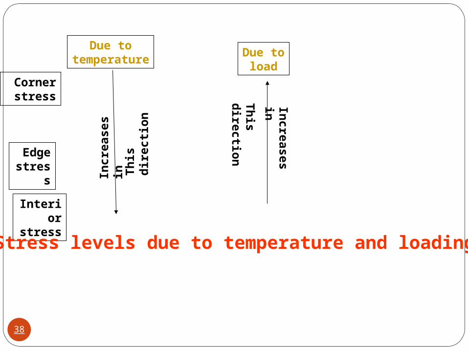
The load stress is the highest in the corner of pavement, less at the edge, and the least in the interior of the pavement.
19

20
Temperature stresses are developed in cement concrete pavement due to variation in slab temperature. This is caused by (i) daily variation resulting in a temperature gradient across the thickness of the slab and (ii) seasonal variation resulting in overall change in the slab temperature. The former results in warping stresses and the later in frictional stresses.
Temperature stress is highest in the interior of the pavement, less at the edge and least at the corner. The corner stress due to temperature is negligible as corners are free to warp.
21
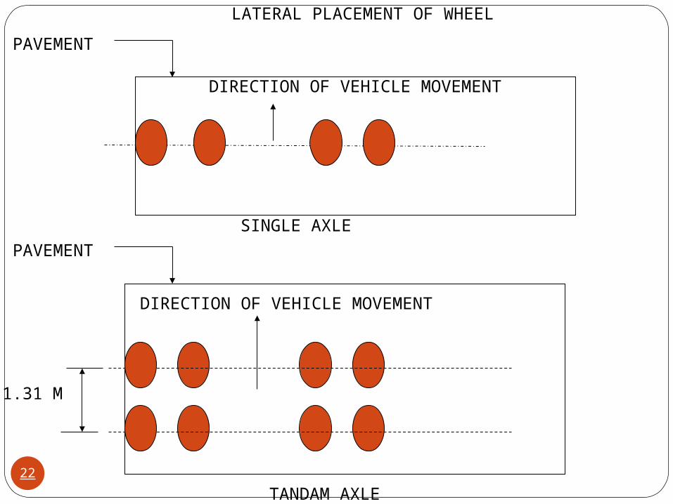
DIRECTION OF VEHICLE MOVEMENT
PAVEMENT
SINGLE AXLE
DIRECTION OF VEHICLE MOVEMENT
PAVEMENT
1.31 M
TANDAM AXLE
LATERAL PLACEMENT OF WHEEL
22
Stresses in Concrete PavementsThe stresses in concrete Pavements are due to both temperature and load .
Stress due to temperatureThe concrete pavement undergoes temperature changes throughout the day .The temperature at the top surface is maximum during the daytime. Similarly during night time the bottom of the pavement has highest temperature. There always exists a temperature gradient across the thickness of the concrete pavement.
2
tCEt
tes
23
Two factors are responsible for the development of temperature stress in the concrete pavement slab- the expansion and contraction due to temperature change, and the temperature gradient across the thickness of the slab. Thus the daily variation in temperature causes warping stresses in reverse directions at the corner, edge and interior regions of the slabs.
2
tCEt
tes
24
Whenever the top and bottom surface of concrete pavement simultaneously possesses different temperatures, the slab tends to wrap downwards or upwards including warping stresses. The difference in temperature between top and bottom of the slab depends mainly on the slab thickness and the climatic conditions of the region.
25
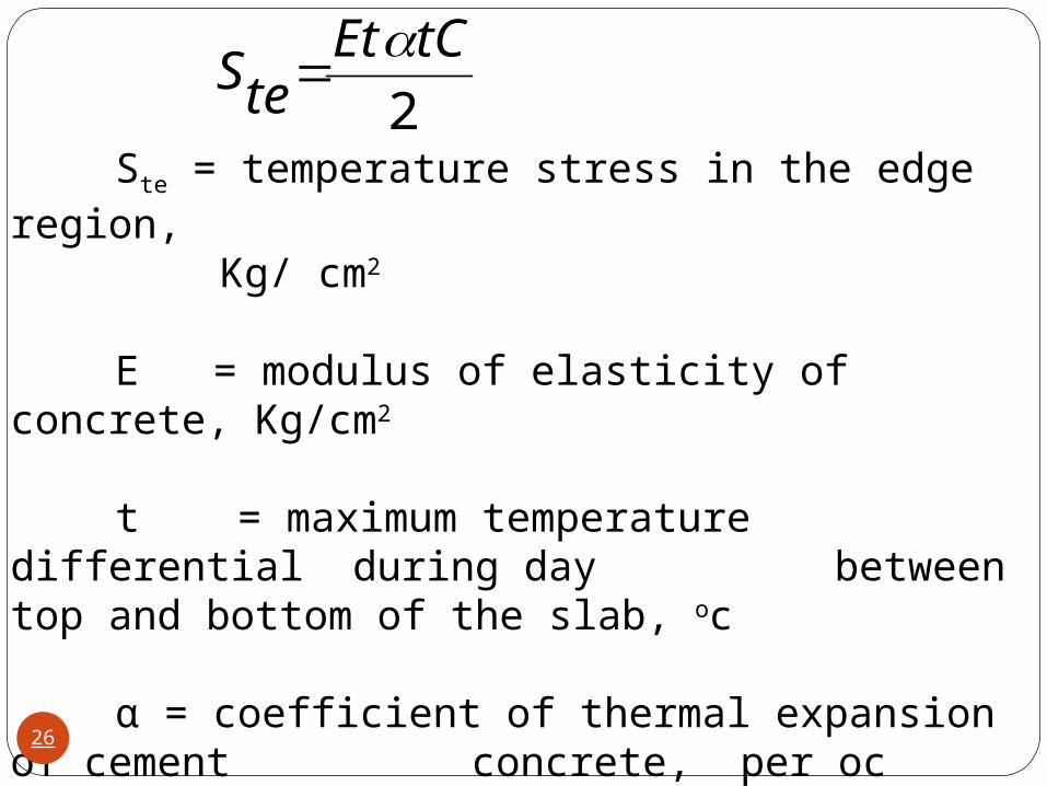
Ste = temperature stress in the edge region, Kg/ cm2
E = modulus of elasticity of concrete, Kg/cm2
t = maximum temperature differential during day between top and bottom of the slab, oc
α = coefficient of thermal expansion of cement concrete, per oc
C = Bradbury`s coefficient, which can be ascertained directly from Bradbury`s chart
2
tCEtteS
26
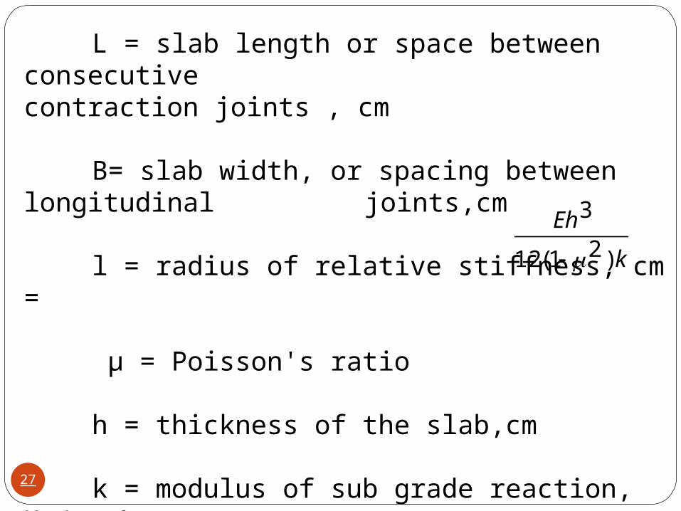
L = slab length or space between consecutive contraction joints , cm
B= slab width, or spacing between longitudinal joints,cm
l = radius of relative stiffness, cm =
µ = Poisson's ratio
h = thickness of the slab,cm
k = modulus of sub grade reaction, Kg/ cm3
k
Eh
)21(12
3
27
Stresses due to loading
Due to loading, the maximum stress is included at the corner, being discontinuous in two directions. The edge stress is lower than that at the corner, being discontinuous in one direction, while interior stress is the maximum among all these.
28
Critical loading PositionSince the pavement slab is finite length and width, either the character or the intensity of maximum stress induced by the application of a given traffic load is dependent on the location of the load on the pavement surface.There are three typical locations the interior, edge and corner, where differing conditions of slab continuity exist. These are termed as critical load positions.
29
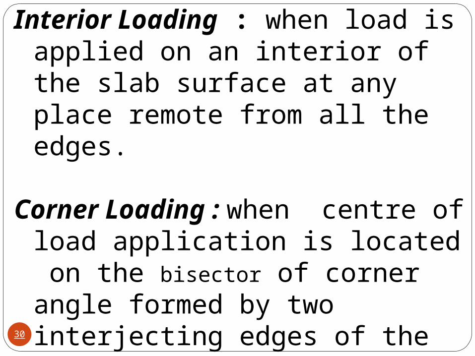
Interior Loading : when load is applied on an interior of the slab surface at any place remote from all the edges.
Corner Loading : when centre of load application is located on the bisector of corner angle formed by two interjecting edges of the slab, and the loaded area is at the corner touching the two corner edges.
30
The stresses at the edge and corner regions are generally found to be more critical for the design of rigid pavement for highways. The Indian Road Congress recommends the following two formulas for the analysis of load stresses at the edge and corner regions and for the design of rigid pavements;
31
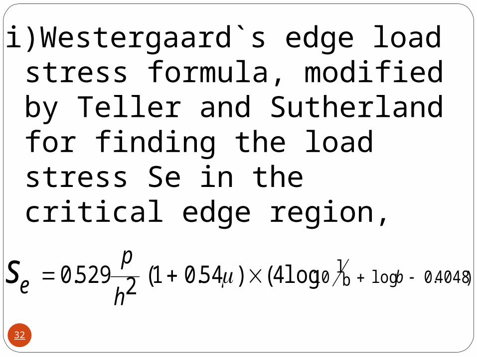
i)Westergaard`s edge load stress formula, modified by Teller and Sutherland for finding the load stress Se in the critical edge region,
)4048.0logbl
10 log4()54.01(2529.0 bh
pes
32
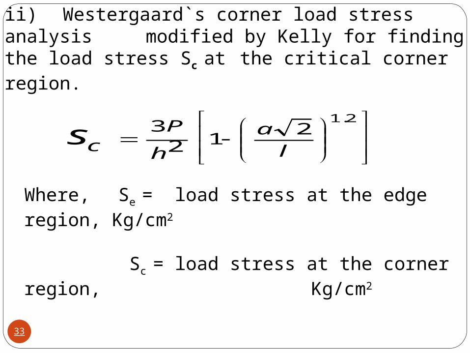
ii) Westergaard`s corner load stress analysis modified by Kelly for finding the load stress Sc at the critical corner region.
2.12
123
l
a
h
Pcs
Where, Se = load stress at the edge region, Kg/cm2
Sc = load stress at the corner region, Kg/cm2
33
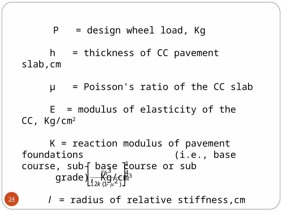
P = design wheel load, Kg
h = thickness of CC pavement slab,cm
µ = Poisson's ratio of the CC slab
E = modulus of elasticity of the CC, Kg/cm2
K = reaction modulus of pavement foundations (i.e., base course, sub- base course or sub
grade), Kg/cm3 l = radius of relative stiffness,cm
= 4
1
)21(12
3
k
Eh
34

b = radius of equivalent distribution of pressure, cm
a = a, when ≥ 1.724 and
b =
a = radius of contact, cm (assumed circular in shape)
h
a
724.1,675.0226.1 h
awhenbha
35
Combined stress due to temperature and loading
It is seen that the corner stress is minimum due to temperature but it is maximum due to load. Thus for design considerations, the combined effects needs to be considered. Moreover, the bottom stress, due to temperature, during night time is compressive, and therefore subtractive in nature with reference to tensile bottom stress due to load. Thus, the temperature stress situation at night time are not considered while determining the combined stress
36
Considering the total combined stress for the regions, viz., corner, edge and interior , for which the load stress decreases in that order while the temperature stress increases, the critical stress condition is reached in the edge region. It is, therefore, necessary that the concrete slab is designed to withstand the stress due to warping the wheel loaded at the edge region. It is also necessary to check the stress at the corner region if the dowel bars are not provided at the transverse joints and if there is no possibility of load transfer by aggregate inter- lock.
37
Due totemperature
Due toload
Edge stress
Corner stress
Incr
ease
s in
Th
is
dir
ecti
on
Interior stress
Increases in
Th
is d
irection
Stress levels due to temperature and loading
38
Moreover, the bottom stress, due to temperature, during night time is compressive, and therefore subtractive in nature with reference to tensile bottom stress due to load. Thus, the temperature stress situation at night time are not considered while determining the combined stress.
39
RIGID PAVEMENT DESIGN – IRC:58-2002
Salient Features of the code
The guidelines cover the design of plain jointed cement concrete pavements. The code is applicable for roads having a daily commercial traffic (vehicles with laden weight exceeding 3 tonne) of over 150. This code is not applicable for low volume roads.
Computation of flexural stress due to the placement of single and tandem axle loads along the edge
Introduction of the cumulative fatigue damage approach in the design
Revision of criteria for design of dowel bars
40

IRC: 58 recommends that both the combined corner stress (load and temperature) and the combined edge should be checked for finding out the most critical stress between the two. The resultant maximum value of flexural stress due to warping and wheel load has to be less than the flexural strength of concrete. The trials are repeated varying thicknesses until the resultant stress is within limit. 41
RIGID PAVEMENT DESIGN – IRC:58-2002
Design Inputs
Wheel load
Design Period
Design Traffic
Temperature Differential
Characteristics of Subgrade and Sub-base
Characteristics of Concrete
42

Wheel load
Data on axle load distribution of the commercial vehicles is required to compute the number of repetitions of single and tandem axles of different weights expected during the design period. An axle load survey is to be conducted for a day in both directions. Higher axle loads induce very high stresses in the pavement and result in consumption of fatigue resistance of concrete. Contribution of different axle load groups towards fatigue damage must be determined for pavement design. For design purpose a tyre pressure of 0.8 Mpa is adopted.
43
For computation of stresses in the pavement , the magnitude of axle loads should be multiplied by Load Safety Factor (LSF).
The value of LSF adopted = 1.2. This takes care of unpredicted heavy truck loads. Basic design of slab is done with 98th percentile axle load from the survey. Design Period
Normally Cement Concrete Pavements have a life span of 30 yearsand should be designed for this periodWhen the traffic intensity can not be predicted accurately for a long periodof time, a design period of twenty years may be considered.
44

Design Traffic Average traffic should be based on 7 day 24 hour count. If growth rate data is not available, an average annual growth rat of 7.5 % is to be adopted.Flexural stresse caused in pavement is maximum when axle loads travel along the edge. However very few vehicle travel along edges. As such a design traffic of 25% of the total two lane two way vehicles is to be considered conservatively.
45

C =
C = Cumulative number of axles during the design period
A = Initial number of axles per day in the year when the road is operational
r = Annual rate of growth of commercial traffic (expressed in decimals)
n = design period in years
Expected number of applications of different axle load groups during the design period can be estimated from the axle load data.
r
rxA n }1)1{(365
46
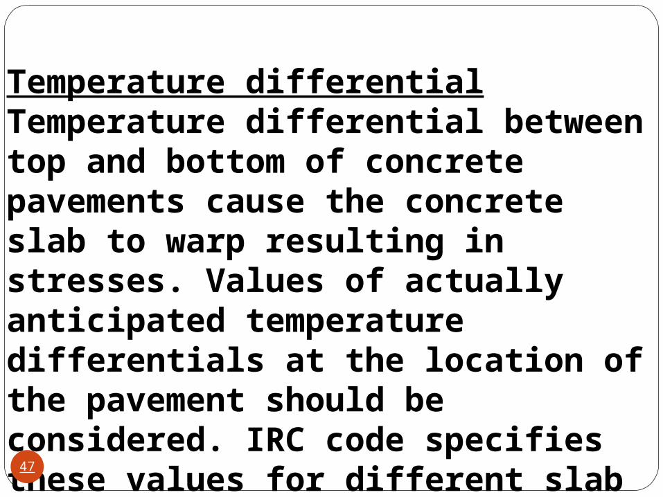
Temperature differentialTemperature differential between top and bottom of concrete pavements cause the concrete slab to warp resulting in stresses. Values of actually anticipated temperature differentials at the location of the pavement should be considered. IRC code specifies these values for different slab thicknesses and for different States.
47
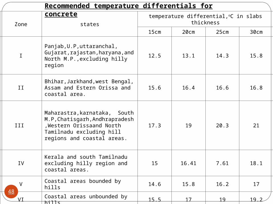
Zone statestemperature differential,oC in slabs thickness
15cm 20cm 25cm 30cm
IPanjab,U.P,uttaranchal, Gujarat,rajastan,haryana,and North M.P.,excluding hilly region
12.5 13.1 14.3 15.8
IIBhihar,Jarkhand,west Bengal, Assam and Estern Orissa and coastal area.
15.6 16.4 16.6 16.8
III
Maharastra,karnataka, South M.P,Chatisgarh,Andhrapradesh,Western Orissaand North Tamilnadu excluding hill regions and coastal areas.
17.3 19 20.3 21
IVKerala and south Tamilnadu excluding hilly region and coastal areas.
15 16.41 7.61 18.1
V Coastal areas bounded by hills 14.6 15.8 16.2 17
VI Coastal areas unbounded by hills 15.5 17 19 19.2
Recommended temperature differentials for concrete
48
Characteristics of subgrade and sub-baseThe strength of subgrade is expressed in terms of modulus of subgrade reaction (k) which is defined as pressure per unit deflection of the foundation as determined by plate bearing test with a 75 cm dia plate as per IS:9214:1974. A frequency of one test per km per lane is recommended for assessment of k-value.Modulus of Subgrade reaction (k)Westergaard’s modulus of subgrade reaction for use in rigid pavement design. It is the load in kg/cm2 on a loaded area of the road bed soil or subgrade divided by the deflection in cms of the road bed soil/subgrade.(kg/cm2 /cm or kg/ kg/cm3).
49
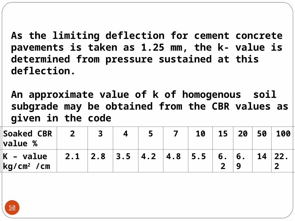
As the limiting deflection for cement concrete pavements is taken as 1.25 mm, the k- value is determined from pressure sustained at this deflection.
An approximate value of k of homogenous soil subgrade may be obtained from the CBR values as given in the code
Soaked CBR value %
2 3 4 5 7 10 15 20 50 100
K – valuekg/cm2 /cm
2.1 2.8 3.5 4.2 4.8 5.5 6.2 6.9 14 22.2
50
A Dry Lean Concrete (DLC) sub base is generally recommended for concrete pavements particularly those with high intensity of traffic as per IRC SP : 49 – 1998.The DLC should have a minimum compressive strength of 7 Mpa at 7 days.
Separation layer between sub base and pavement.Foundation layer below concrete slabs should be smooth to reduce the inter layer friction. A separation membrane of minimum thickness of 125 micron polythene is recommended between concrete pavement and DLC.
51

Characteristics of Concrete
Design StrengthSince the concrete pavements fail due to bending stresses, it is necessary that their design is based on the flexural strength of concrete. The mix should be so designed that the minimum strength requirement is 45 kg/cm2 .
52
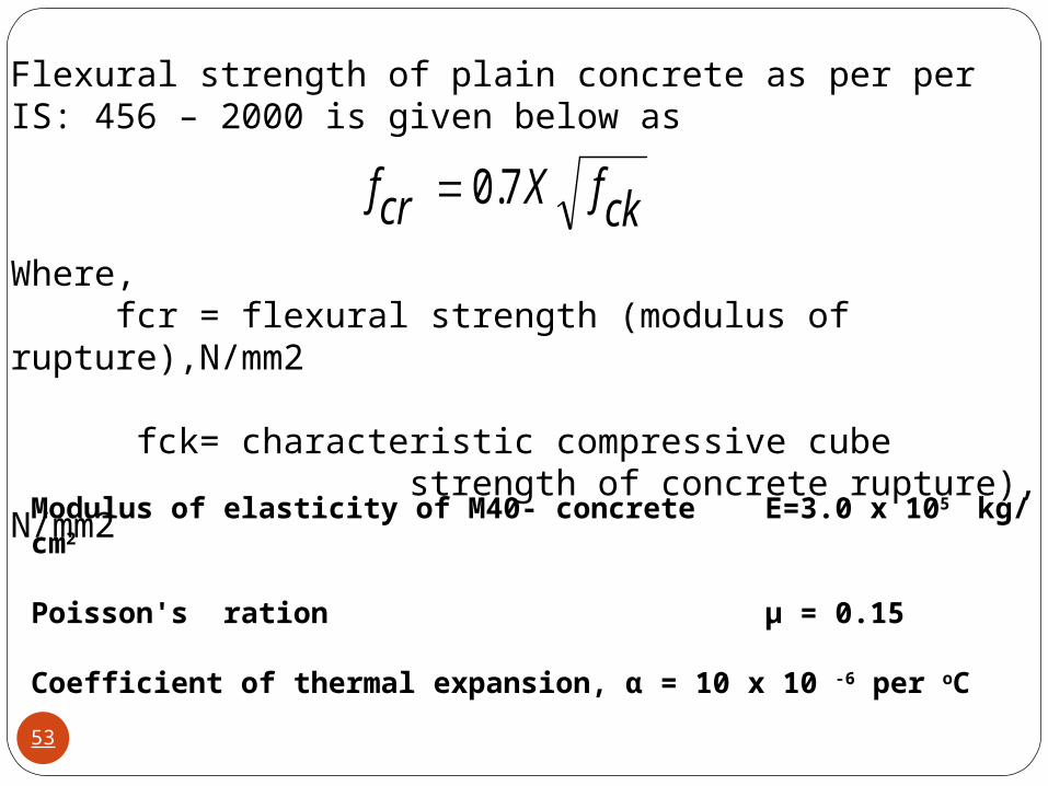
Flexural strength of plain concrete as per per IS: 456 – 2000 is given below as
Where,fcr = flexural strength (modulus of rupture),N/mm2
fck= characteristic compressive cube strength of concrete rupture), N/mm2
ckfXcrf 7.0
Modulus of elasticity of M40- concrete E=3.0 x 10⁵ kg/ cm2
Poisson's ration µ = 0.15
Coefficient of thermal expansion, α = 10 x 10 -6 per oC
53
Fatigue behaviour of Cement ConcreteDue to repeated application of flexural stresses by the traffic loads, a progressive fatigue damage takes place in the Cement Concrete slab in the form of micro –cracks. The ratio between the flexure stress due to the load and the flexural strength of concrete is termed as the stress ratio (SR). If the SR is less than 0.45 , the concrete is expected to sustain indefinite number of repetitions .
54
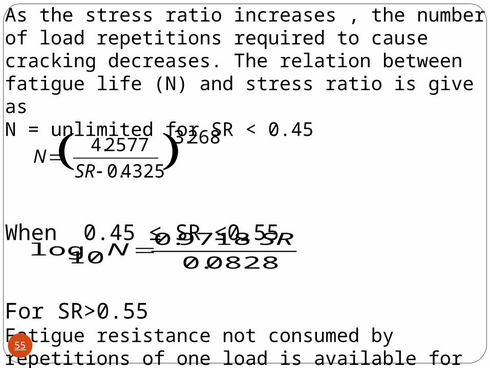
As the stress ratio increases , the number of load repetitions required to cause cracking decreases. The relation between fatigue life (N) and stress ratio is give asN = unlimited for SR < 0.45
When 0.45 ≤ SR ≤0.55
For SR>0.55Fatigue resistance not consumed by repetitions of one load is available for repetitions to other loads.
268.3
4325.0
2577.4
SR
N
0828.0
9718.010log
SRN
55
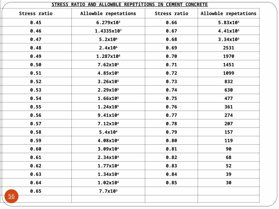
STRESS RATIO AND ALLOWBLE REPETiTIONS IN CEMENT CONCRETE
Stress ratio Allowble repetations Stress ratio Allowble repetations
0.45 6.279x10³ 0.66 5.83x10³
0.46 1.4335x10⁷ 0.67 4.41x10³
0.47 5.2x10⁶ 0.68 3.34x10³
0.48 2.4x10⁶ 0.69 2531
0.49 1.287x10⁶ 0.70 1970
0.50 7.62x10⁵ 0.71 1451
0.51 4.85x10⁵ 0.72 1099
0.52 3.26x10⁵ 0.73 832
0.53 2.29x10⁵ 0.74 630
0.54 1.66x10⁵ 0.75 477
0.55 1.24x10⁵ 0.76 361
0.56 9.41x10⁴ 0.77 274
0.57 7.12x10⁴ 0.78 207
0.58 5.4x10⁴ 0.79 157
0.59 4.08x10⁴ 0.80 119
0.60 3.09x10⁴ 0.81 90
0.61 2.34x10⁴ 0.82 68
0.62 1.77x10⁴ 0.83 52
0.63 1.34x10⁴ 0.84 39
0.64 1.02x10⁴ 0.85 30
0.65 7.7x10³
56
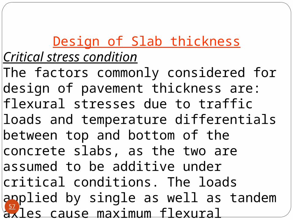
Design of Slab thicknessCritical stress conditionThe factors commonly considered for design of pavement thickness are: flexural stresses due to traffic loads and temperature differentials between top and bottom of the concrete slabs, as the two are assumed to be additive under critical conditions. The loads applied by single as well as tandem axles cause maximum flexural stresses when the tyre imprint touches the longitudinal edge of slab.
57
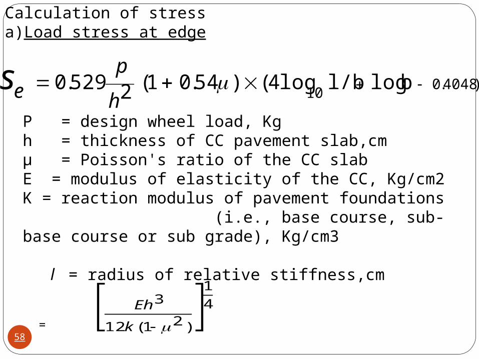
Calculation of stressa) Load stress at edge
P = design wheel load, Kgh = thickness of CC pavement slab,cmµ = Poisson's ratio of the CC slabE = modulus of elasticity of the CC, Kg/cm2K = reaction modulus of pavement foundations (i.e., base course, sub- base course or sub grade), Kg/cm3
l = radius of relative stiffness,cm
=
)4048.010
b logl/b log4()54.01(2529.0 h
pes
41
)21(12
3
k
Eh
58
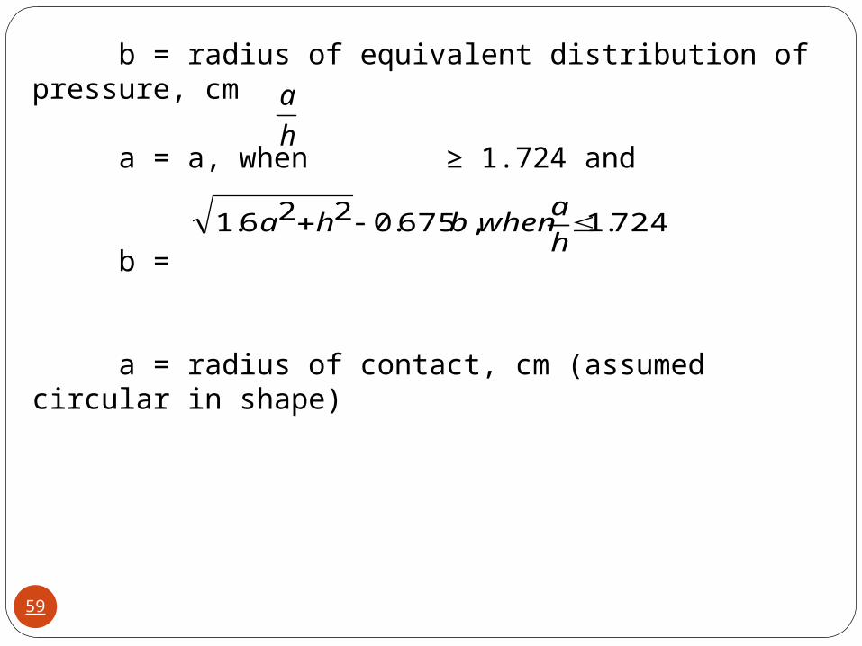
b = radius of equivalent distribution of pressure, cm
a = a, when ≥ 1.724 and
b =
a = radius of contact, cm (assumed circular in shape)
h
a
724.1,675.0226.1 h
awhenbha
59
The edge stress values curves for single axle as well as tandem axles are available for different magnitudes of axle loads. These charts are given at Appendix-1 of the code.
These curves are plotted considering slab thickness vs flexural stress for different k values.
These curves cover single axle load for a range from 6t to 18 t (6, 8,10,12,14,16,18,20,22,24 t) and for tandem axle load for a range from 12t to 44 t (12,16,20,24,28,32,36,40,44 t).
60
Temperature stress at edge Using Westergaard’s approach Bradbury obtained the following equation for computation of the temperature stress at the edge region.
61

Ste = temperature stress in the edge region, Kg/ cm2
E = modulus of elasticity of concrete, Kg/cm2
t = maximum temperature differential during day between top and bottom of the slab, oc
α = coefficient of thermal expansion of cement concrete, per oc
C = Bradbury`s coefficient, which can be ascertained directly from Bradbury`s chart
2
tCEtteS
62

L = slab length or space between consecutive contraction joints , cm
B= slab width, or spacing between longitudinal joints,cm
l = radius of relative stiffness, cm =
µ = Poisson's ratio
h = thickness of the slab,cm
k = modulus of sub grade reaction, Kg/ cm3
k
Eh
)21(12
3
63
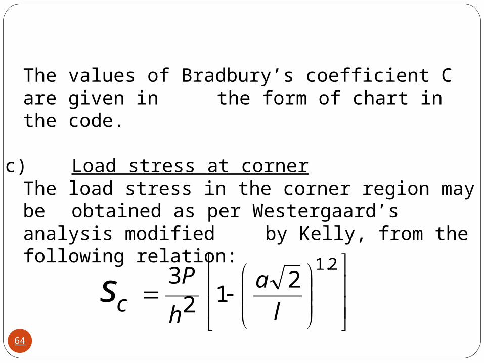
The values of Bradbury’s coefficient C are given in the form of chart in the code.
c)Load stress at cornerThe load stress in the corner region may be obtained as per Westergaard’s analysis modified by Kelly, from the following relation:
2.12
123
l
a
h
Pcs
64
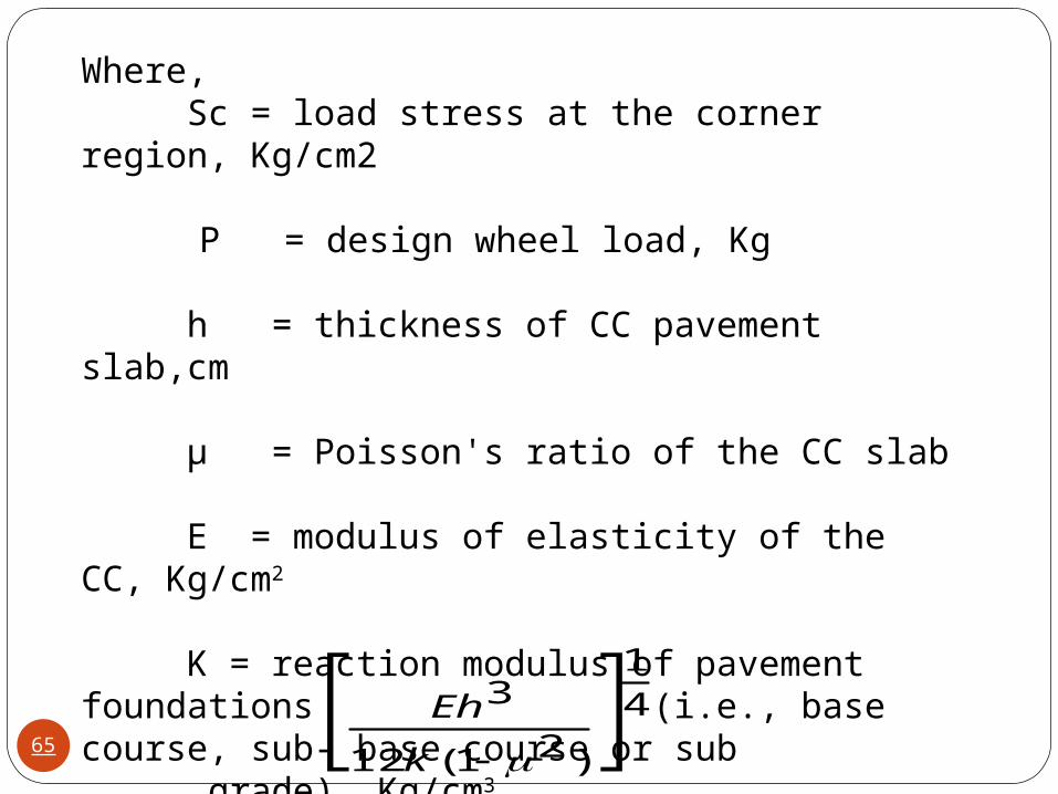
Where,Sc = load stress at the corner region, Kg/cm2
P = design wheel load, Kg
h = thickness of CC pavement slab,cm
µ = Poisson's ratio of the CC slab
E = modulus of elasticity of the CC, Kg/cm2
K = reaction modulus of pavement foundations (i.e., base course, sub- base course or sub
grade), Kg/cm3 l = radius of relative stiffness,cm
= 41
)21(12
3
k
Eh65
b = radius of equivalent distribution of pressure, cm
a = a, when ≥ 1.724 and
b =
a = radius of contact, cm (assumed circular in shape)
d) Temperature stress in the corner is negligible as the corners are relatively free to warp and therefore may be ignored
h
a
724.1,675.0226.1 h
awhenbha
66
Recommended Design Procedure:Step 1: Stipulate design values for the various
parametersStep 2: Decide types and spacing of jointsStep 3: Select trial thickness of pavement slabStep 4: Compute the repetitions of axle loads of different
magnitudes during the design period.Step 5: Calculate the stresses due to single and tandem
axle loads and determine the cumulative fatigue damage (CDF)
Step 6: If the CDF is more than 1.0 , select a higher thickness and repeat the steps 1 to 5
Step 7: Compute the temperature stress at the edge and if the sum of the temperature stress and the flexural stress due to the highest wheel load is greater than the modulus of rupture, select higher thickness and repeat the steps 1 to 6
67
DESIGN OF JOINTSJoints are provided in cement concrete roads
for expansion, contraction and warping of slabs due to various temperatures in slabs.
Great care is needed in the design and construction of joints in Cement Concrete Pavements, as these are critical locations having significant effect on the pavement performance. The joints also need to be effectively sealed , and maintained well. The recommendations of the IRC: 15, have to followed with regard to joint layout and contraction joint spacings
68
JOINTS IN CONCRETE
PAVEMENTS
LONGITUDINAL JOINTS
TRANSFERS JOINTS
WARPINGJOINTS
CONSTRUCTION
JOINTS
EXPANSION JOINTS
CONTRACTION JOINTS
CONSTRUCTION
JOINTS
Cement Concrete Pavements have transverse and longitudinal joints. Various types of joints are shown below:
69
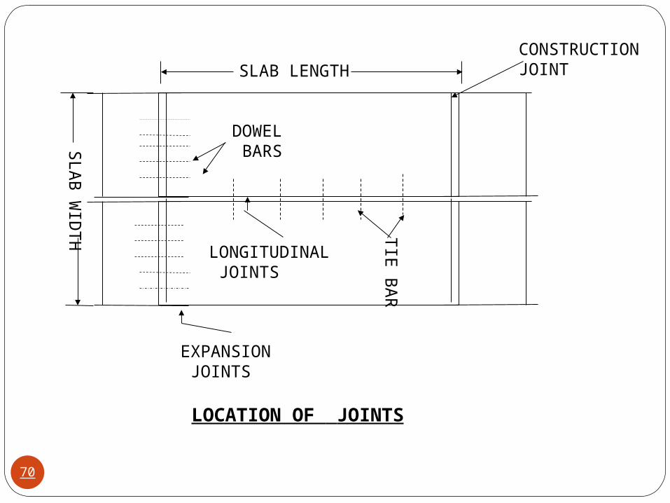
SLAB LENGTHCONSTRUCTION JOINT
SLA
B W
IDT
H
EXPANSION JOINTS
LONGITUDINAL JOINTS
TIE
BA
R
DOWEL BARS
LOCATION OF JOINTS
70
Longitudinal Joints. Longitudinal joints are provided in cement concrete roads which have width more than 4.5 m. The longitudinal joints are provided to prevent longitudinal cracking in the cement concrete pavements. This type of joints acts like a hinge and helps to maintain the two slabs together , at the same level. In the longitudinal joint tie bars are provided to hold the adjacent slabs together. 71
Tie bars are not load transfer devices, but serve as a means to tie two slabs. Hence tie bars must be deformed or hooked and must be firmly anchored into the concrete to function properly. They are smaller than dowel bars and placed at large intervals. They are provided across longitudinal joints.
72
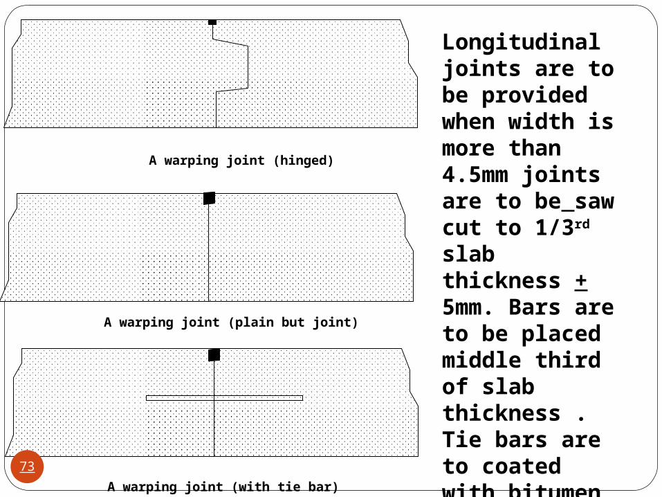
A warping joint (hinged)
A warping joint (plain but joint)
A warping joint (with tie bar)
Longitudinal joints are to be provided when width is more than 4.5mm joints are to be saw cut to 1/3rd slab thickness + 5mm. Bars are to be placed middle third of slab thickness . Tie bars are to coated with bitumen painted for 75mm on either side.73

Tie Bars. Tie bars, either deformed steel bars or connectors, are designed to hold the faces of abutting slabs in firm contact. Tie bars are designed to withstand the maximum tensile forces required to overcome subgrade drag.They are not designed to act as load – transfer devices.Design of Tie barsThe area of steel required per meter length of joint may be computed using the following formula:
74
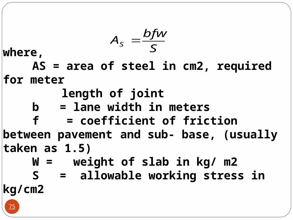
S
bfwAS
where,AS = area of steel in cm2, required for meter
length of jointb = lane width in metersf = coefficient of friction between pavement and sub- base, (usually taken as 1.5)W = weight of slab in kg/ m2S = allowable working stress in kg/cm2
75
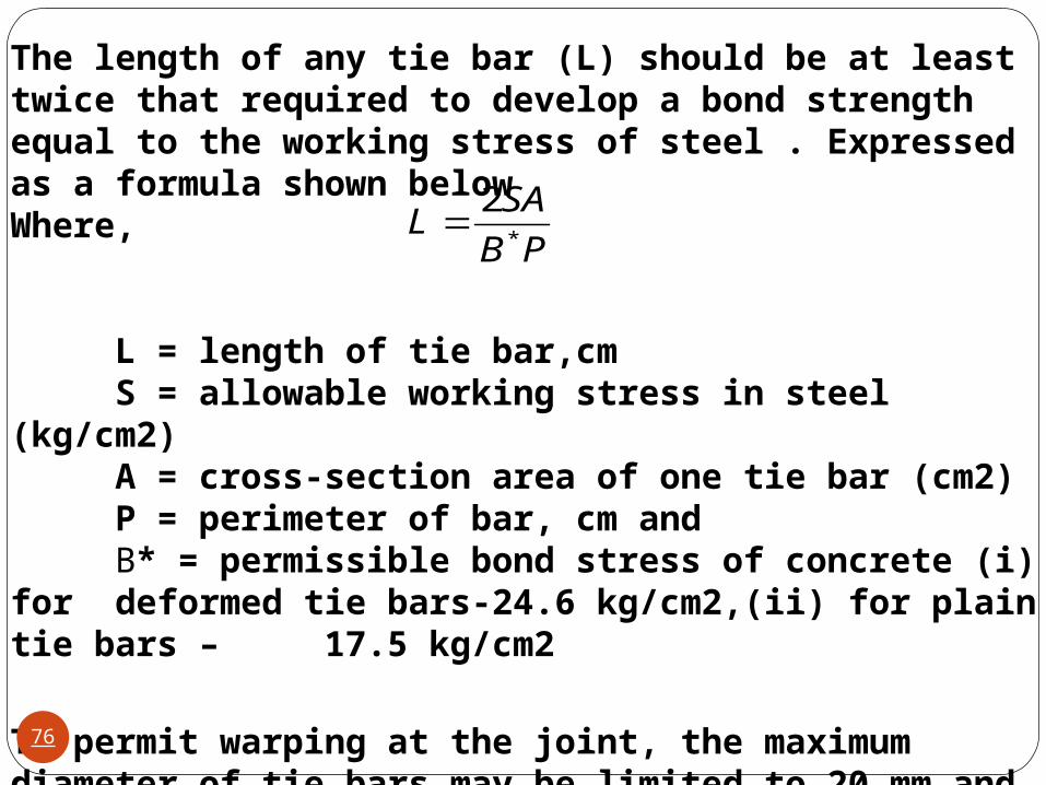
The length of any tie bar (L) should be at least twice that required to develop a bond strength equal to the working stress of steel . Expressed as a formula shown below Where,
L = length of tie bar,cmS = allowable working stress in steel (kg/cm2)A = cross-section area of one tie bar (cm2)P = perimeter of bar, cm andB* = permissible bond stress of concrete (i) for
deformed tie bars-24.6 kg/cm2,(ii) for plain tie bars – 17.5 kg/cm2
To permit warping at the joint, the maximum diameter of tie bars may be limited to 20 mm and they should not be spaced more than 75 cm apart.
PB
SAL
*
2
76
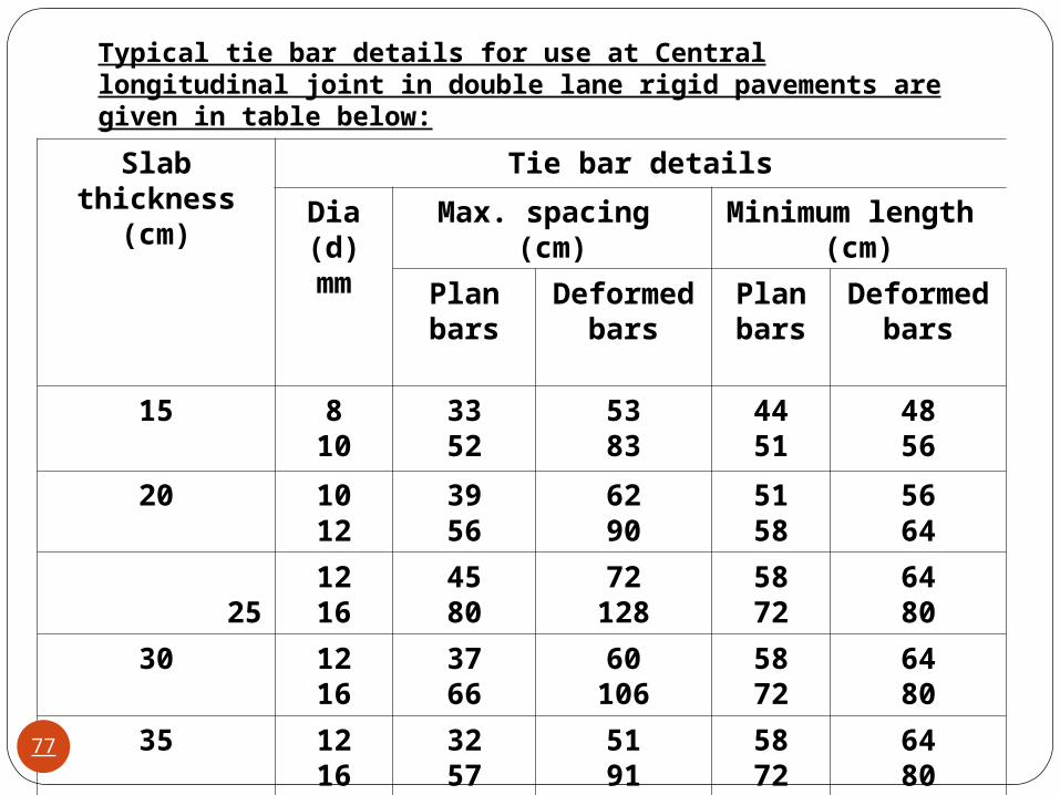
Slab thickness(cm)
Tie bar details
Dia (d) mm
Max. spacing (cm) Minimum length (cm)
Plan bars
Deformed bars
Plan bars
Deformed bars
15 810
3352
5383
4451
4856
20 1012
3956
6290
5158
5664
25
1216
4580
72128
5872
6480
30 1216
3766
60106
5872
6480
35 1216
3257
5191
5872
6480
Typical tie bar details for use at Central longitudinal joint in double lane rigid pavements are given in table below:
77

Different types of transverse joints are:• Expansion Joints• Contraction joints• Construction joints
Expansion JointsConcrete expands with increase in temperature. Unless there is a provision for expansion, the concrete slab may buckle outwards and break.Expansion joints are full depth joints provided at specified intervals along transverse direction of the slab. Generally , dowel bars bars are placed across the expansion joints to take care of the load transfer.
78
The purpose of the expansion joint is to allow the expansion of the pavement due to rise in temperature with respect to construction temperature. The design consideration are: Provided along the longitudinal direction, design involves finding the joint spacing for a given expansion joint thickness (say 2.5 cm specified by IRC) subjected to some maximum spacing (say 140 as per IRC) Dowel bars The purpose of the dowel bar is to effectively transfer the load between two concrete slabs and to keep the two slabs in same height. The dowel bars are provided in the direction of the traffic (longitudinal). The design considerations are: Mild steel rounded bars, bonded on one side and free on other side
79
Load transfer at Transverse jointsLoad transfer to relieve part of the load stress at transverse joints is provided by means of mild steel dowel bars.
Load transfer devices for transverse joints should possess the following attributes.
• They should be simple in design, be practical to install, and permit complete encasement by the concrete.
• They should properly distribute the load stresses without overstressing the concrete at its contact with the device.
80
• They should offer little resistance to longitudinal movement of the joint at any time.
• They should be mechanically stable under the wheel load weights and frequencies that will prevail in practice.
• They should be resistance to corrosion when used in those geographic locations where corrosive elements area problem.(Various types of
coatings are often used to minimize corrosion.)
Bearing stress in the concrete is responsible for performance of the joints for the dowel bars. 81
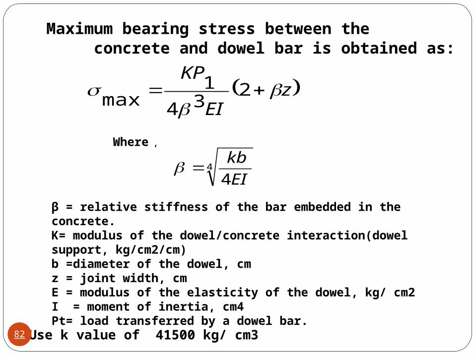
Maximum bearing stress between the concrete and dowel bar is obtained as:
zEI
KP
2
34
1max
4
4EI
kb
Where ,
β = relative stiffness of the bar embedded in the concrete.K= modulus of the dowel/concrete interaction(dowel support, kg/cm2/cm)b =diameter of the dowel, cmz = joint width, cmE = modulus of the elasticity of the dowel, kg/ cm2I = moment of inertia, cm4Pt= load transferred by a dowel bar.
Use k value of 41500 kg/ cm3 82
525.9
16.10 ckb
fbF
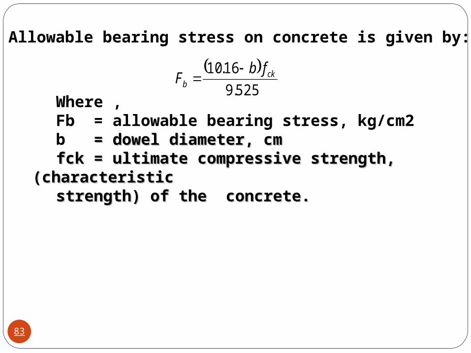
Allowable bearing stress on concrete is given by:
Where ,Fb = allowable bearing stress, kg/cm2b = dowel diameter, cm = dowel diameter, cmfck = ultimate compressive strength,(characteristic fck = ultimate compressive strength,(characteristic
strength) of the concrete.strength) of the concrete.
83
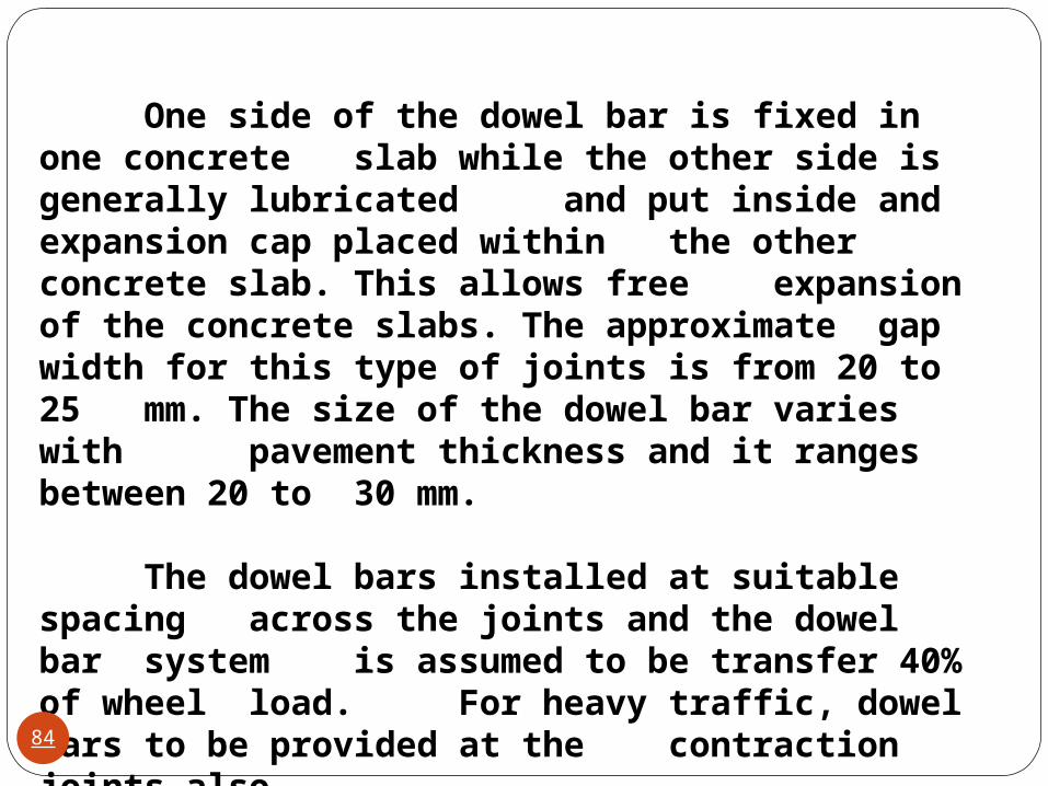
One side of the dowel bar is fixed in one concrete slab while the other side is generally lubricated and put inside and expansion cap placed within the other concrete slab. This allows free
expansion of the concrete slabs. The approximate gap width for this type of joints is from 20 to 25 mm. The size of the dowel bar varies with
pavement thickness and it ranges between 20 to 30 mm.
The dowel bars installed at suitable spacing across the joints and the dowel bar system is assumed to be transfer 40% of wheel load. For heavy traffic, dowel bars to be provided at the contraction joints also .
84
It is recommended that the dowel bar system designed for the expansion joint should be used for contraction joints also.
Dowel bars are not required for slabs of small thickness and they need not be provided for slab of less than 15 cm thickness.
Recommended diameter and length of dowel bars is given in the table below:
85
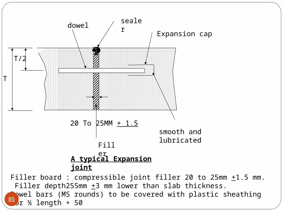
dowelsealer
Expansion cap
smooth and lubricated
Filler
A typical Expansion joint
Filler board : compressible joint filler 20 to 25mm +1.5 mm. Filler depth255mm +3 mm lower than slab thickness.Dowel bars (MS rounds) to be covered with plastic sheathing for ½ length + 50
T/2
T
20 To 25MM + 1.5
86
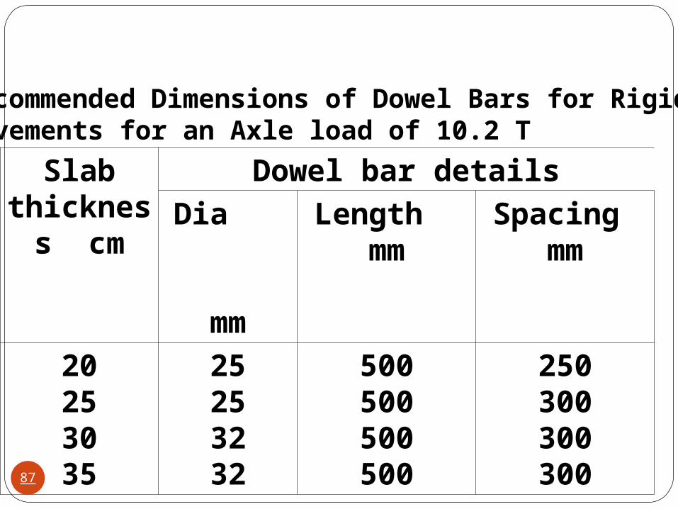
Slab thickness
cm
Dowel bar details
Dia mm
Length mm
Spacing mm
20253035
25253232
500500500500
250300300300
Recommended Dimensions of Dowel Bars for Rigid Pavements for an Axle load of 10.2 T
87
Contraction jointsContraction joints are provided to permit the contraction of the slab and to take care of shrinkage of concrete slabs. They are provided along transverse direction at regular intervals. These joints are spaced closer than expansion joints. Load transference at these joints is provided through the physical interlocking by the aggregates projecting out at the joints. Dowel bars may be or may not be placed to assist the load transfer mechanism between the two slabs. Sometimes , a dummy groove ( or partial cut) is placed as contraction joint .
88

sealent Smooth and lubricated
Dowel bar
A typical contraction joint
Longitudinal joints are to be provided when width is more than 4.5 mm.joints are to be saw cut to 1/3rd slab thick +5. Bars are to be placed middle third of slab thickness .Tie bars are to be coated with bitumen paint for 75 mm on either side.
89
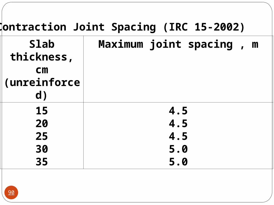
Slab thickness, cm
(unreinforced)
Maximum joint spacing , m
1520253035
4.54.54.55.05.0
Contraction Joint Spacing (IRC 15-2002)
90
Construction jointsConstruction joints are the joints between pavement sections that are constructed at different periods of time. A construction joint could be along the longitudinal direction or the transverse direction, and an effort is made such that it conincides with the locations of other joist. Thus a construction joint may be expansion or longitudinal joint. As per modern practice of concrete pavement construction, construction is carried out round the clock and therby provision of construction joints is eliminated.
91
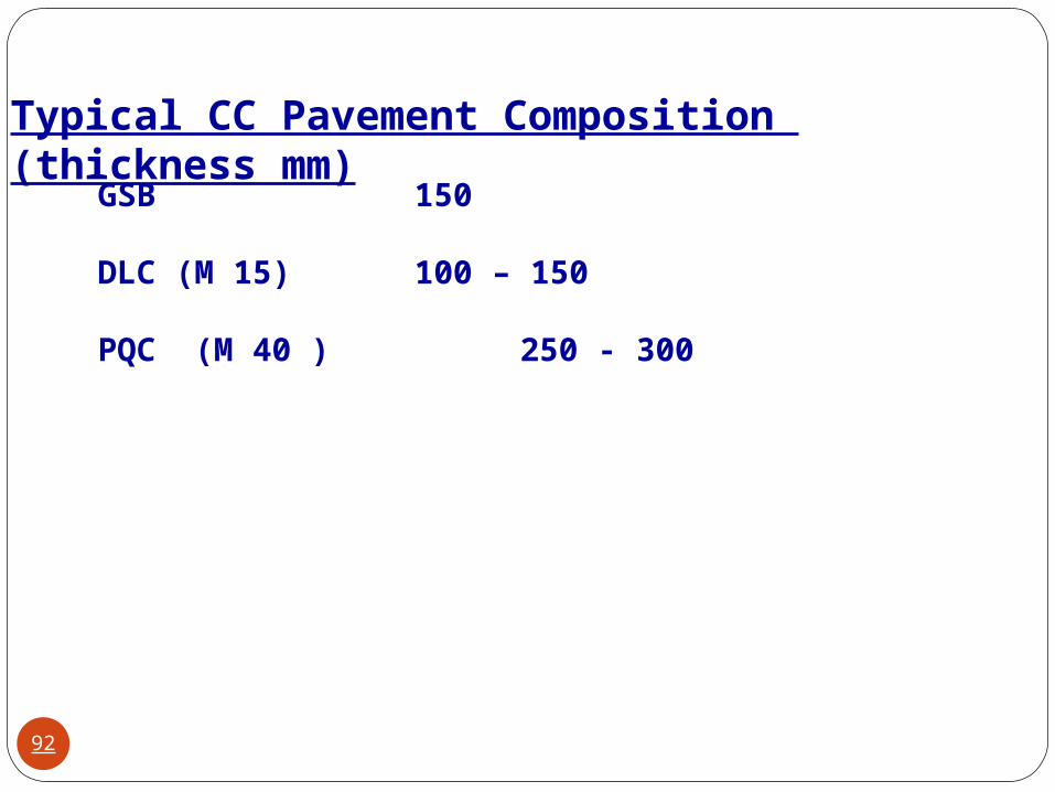
Typical CC Pavement Composition (thickness mm)GSB 150
DLC (M 15) 100 – 150
PQC (M 40 ) 250 - 300
92
Reference
IS : 10262 Recommended Guideline for Concrete Mix DesignIS – SP : 23 : Handbook for Concrete MixesIRC- 58-2002 Guidelines for the Design of Rigid Pavements for
Highways
This code is applicable for roads having a daily commercial traffic (vehicles with laden weight exceeding 3 tonne) of over 150. This code is not applicable for low volume roads.
IRC -15: 2002 Standard Specifications and Code of Practice for Construction of concrete Roads.
IRC SP: 17 – 1977 Recommendation about overlays on CC Pavements.
IRC SP : 49-1988 Guidelines for the use of DLC on subbase for Rigid Pavement.
IRC:SP:62-2004 Concrete pavement – Rural Roads93

94