reporting in brachytherapy
TRANSCRIPT
8/11/2019 Reporting in Brachytherapy
http://slidepdf.com/reader/full/reporting-in-brachytherapy 1/63
6Reporting in Brachytherapy: Dose and VolumeSpecificationRichard Pötter, Erik Van Limbergen, André Wambersie
Chapter Outline
1 Introduction1.1 From prescribing to recording and reporting1.2 The three levels of dose and volume evaluation for reporting
2 Clinical Aspects –Volumes2.1 Gross Tumour Volume (GTV)2.2 Clinical Target Volume (CTV)2.3 Planning Target Volume (PTV)2.4 Treated Volume
2.5 Irradiated Volume2.6 Organs At Risk (OAR)
3 Reporting the Technical Aspects of the BrachytherapyTreatment3.1 Description of the radioactive sources3.2 Source pattern3.3 The applicator3.4 Type of afterloading and source movement3.5 The “Systems”
4 Specification of the Source “Strength” (Intensity) inBrachytherapy4.1 The Reference Air Kerma Rate (RAKR)4.2 The Total Reference Air Kerma (TRAK)4.3 Additional specification of photon sources used for intraluminal
applications4.4 Specification of beta-ray sources used for endovascular brachytherapy
5 Reporting the Time-Dose Pattern in Brachytherapy
5.1 Description of the time-dose pattern5.2 The biologically weighted dose
6 Interstitial Therapy: Definition of Concepts, Doses andVolumes for Reporting6.1 Some “historical” systems in interstitial therapy6.2 Dose distribution in interstitial therapy6.3 Reference points (dose levels) for reporting interstitial therapy6.4 Volumes for reporting in interstitial therapy6.5 Dose uniformity parameters
8/11/2019 Reporting in Brachytherapy
http://slidepdf.com/reader/full/reporting-in-brachytherapy 2/63
6.6 Additional representation of the dose distribution6.7 Recommendations for reporting interstitial therapy : Summary
7 Intraluminal Brachytherapy:Definition of Concepts, Doses and Volumes for Reporting7.1 Introduction
7.2 Dose distribution in intraluminal brachytherapy7.3 Clinical aspects7.4 Reference points for reporting intraluminal brachytherapy7.5 Dimensions of volumes for reporting7.6 Recommendations for reporting intraluminal brachytherapy : Summary
8 Intracavitary Brachytherapy for Cervix Cancer Treatment:Definition of Concepts, Quantities, Doses and Volumes forReporting8.1 Introduction-The”historical systems”8.2 Dose distribution in intracavitary brachytherapy for cervix cancer
8.3 Reference points for reporting intracavitary brachytherapy8.4 Volumes for reporting and their dimensions8.5 Organs At Risk (OAR): reference points and volumes8.6 Quantities, reference points and volumes recommended for reporting
intracavitary therapy for cervix carcinoma – Summary
9 References

8/11/2019 Reporting in Brachytherapy
http://slidepdf.com/reader/full/reporting-in-brachytherapy 3/63
Reporting in Brachytherapy 155
1 Introduction
Exchange of information and clinical results between radiation oncology centres requires uniformityand agreement on the methods used to specify the doses and the volumes to which these doseshave been delivered. This requires an agreement on definitions of terms and concepts necessary toreport irradiation techniques.
The ICRU recognised the importance of uniformity in reporting: it has been involved for severaldecades in an effort to harmonise the concepts, definitions of terms, dose and volume specificationand dose determination in radiation therapy. Several reports have been published for external beamtherapy (ICRU 42,44,47). “Dose and volume specification for reporting intracavitary therapy ingynecology“ was published in 1985 (43) (a revision is at the moment in preparation). „Dose andvolume specification for reporting interstitial therapy“ was published in 1997 (45).
This chapter is based mainly on the recommendations of the International Commission on RadiationUnits and Measurements (43,44,45,47,48) and the recent GEC-ESTRO recommendations (86).
1.1 From prescribing to recording and reporting
1.1.1 Treatment prescription
The prescription of a treatment is the responsibility of the radiation oncologist (or the radiationoncology team) in charge of the patient. It is not the aim of this chapter (nor the role of the ICRU) tomake recommendations about the treatment prescription, i.e., about the general rationale of thetreatment, dose level or technical aspects of the treatment.
In fact, different methods of treatment prescription are used at present by different radiationoncologists or in different radiotherapy centres, depending on local tradition, personal training andexperience, and local conditions.
For example, for cervix brachytherapy, some centres prescribe the treatment in terms of the TRAK(or mg.h which is its “historical” equivalent). Many prescribe the dose at point A, while morerecently, some centres orientate their prescription towards volume evaluation. The maximum“tolerable” dose to organs at risk is also used as a prescription method.
In interstitial therapy, some centres prescribe the minimum dose to the CTV, others the “MeanCentral Dose”, others the dose on the envelope surface encompassing the CTV, etc.
In endoluminal brachytherapy, the dose is prescribed at different distances from the centre of thesource or at different depths in the tissues. For example, in endovascular brachytherapy, the dose isprescribed at 2 mm from the source axis, or at 1 or 2 mm from the tissue surface, etc.
1.1.2 Recording the radiation treatment
Recording the treatment parameters as completely and accurately as possible in the patient chartmust be performed in a radiation therapy department for several purposes:
- to ensure further care and follow-up of the patients,- to keep treatment conditions reproducible, safe and constant,
8/11/2019 Reporting in Brachytherapy
http://slidepdf.com/reader/full/reporting-in-brachytherapy 4/63
156 Reporting in Brachytherapy
- to build up progressively clinical experience in the department progressively resulting in improvedtechniques,
- to be able to exchange information on treatment conditions with other centres,- to be able to „reconstruct“ the treatment conditions when needed: interpretation of the treatment
outcome(s), accident, implementation of a quality assurance program, or a research anddevelopment program, etc.
It is important that sufficient information be exchanged, and agreement be reached, between themedical, physics and radiographer staff, on the methods of recording the treatment parameters. Theterms and concepts to be used should be clearly defined.
The amount of information to be recorded depends on (1) the technique and the purpose of thetreatment (cure or palliation), and (2) the situation of the department as far as equipment and staff isconcerned.
1.1.3 Reporting the treatment
Prescribing the treatment is the responsibility of the radiation-oncology team in charge of the
patient, recording the treatment parameters is the responsibility of the department, butharmonisation in reporting is mandatory for the reliable exchange of information between centres.
Harmonisation in reporting implies an agreement on (1) concepts and definitions of terms, and (2) ageneral approach on how to report a treatment. Agreement must also be reached on the (minimum)information that should be contained in the report. Because, however, of the huge amount ofinformation now available in some situations, the part of this information, which is relevant forreporting, must be selected.
Comparison of treatments performed in different centres using different treatment conditions impliesagreement on a certain number of reference parameters. As a first basic option, reference pointsmust be selected and the dose to these points can be compared. Alternatively, fixed dose levels canbe selected and the dimensions of the corresponding volumes can be compared. In brachytherapy,
the reference points can be related to anatomy or to the source and/or the applicator. In the past,selection of reference points was the most common approach for comparison. With advancingimaging and dosimetric techniques, the volume concept becomes a realistic option. For the future,the volume concept will probably be a major factor in the development of brachytherapy (as inexternal beam therapy) and will become more and more clinically relevant.
Recommendations for improving harmonisation in reporting interstitial, intraluminal and intracavitarybrachytherapy therapy are presented in this chapter on “reporting in brachytherapy”. However for thefuture, and without interfering with the prescription itself, nor with the local policy for recording thetreatment parameters, it is obvious that all procedures would be simplified and faster, and the risk ofconfusion and accident would be reduced if the same definitions of terms and concepts and thesame methods for specifying the doses and the volumes were used for prescribing, recording and
reporting. This would also facilitate multi-centre research and cooperative clinical trials.
8/11/2019 Reporting in Brachytherapy
http://slidepdf.com/reader/full/reporting-in-brachytherapy 5/63
Reporting in Brachytherapy 157
1.2 The three levels of dose and volume evaluation for reporting
Different levels of completeness and accuracy can be identified for reporting. Three levels have beenidentified for conventional photon beam therapy (44,47); they are proposed in the present report forbrachytherapy (90) .
Level 1
This implies reporting the minimum of data that are required to perform brachytherapy in an efficientand safe way.
These data should be available in all centres, whatever their situation regarding staff and equipment.In well staffed and equipped centres, reporting at Level 1 may be sufficient for certain treatmenttechniques.
Level 2
Reporting at Level 2 must contain all the information of Level 1.
In addition, reporting at Level 2 contains the information needed to perform a state of the arttreatment. It allows the exchange of more complete and relevant information between differentcentres. The conditions for reporting at Level 2 usually require a well equipped and staffed centre.
It implies that the relevant volumes (p. 158) and organs at risk (p. 163) can be defined with modernimaging techniques under reliable conditions (typically, a series of CT and/or MRI sections, but otherimaging techniques, such as ultrasound or PET, may bring additional relevant information). At Level2, it is also assumed that 3-D dose distributions are available; dose-volume histograms can then bederived from these two sets of information.
Depending on local conditions, target and organ reconstruction is based on a full CT examination or
a limited number of CT images (sections). Interpolation between images is therefore sometimesneeded; the accuracy of the reconstructed target and organ dimensions depends on the number ofsections available.
Level 3
Reporting at Level 3 is characterised by individualised, usually very complex and often evolvingtechniques (e.g., “3-D image based intensity modulated brachytherapy”).Reporting at Level 3 contains all information from Levels 1 and 2. No additional reportingrequirements are established yet, but comprehensive information should be given.
All radiation therapy techniques are continuously evolving and more sophisticated equipment and
software continue to be commercially available. Therefore, with time, the boundaries between thethree levels, as defined above, may change.
8/11/2019 Reporting in Brachytherapy
http://slidepdf.com/reader/full/reporting-in-brachytherapy 6/63
158 Reporting in Brachytherapy
2 Clinical Aspects – Volumes
It is difficult to report a treatment correctly without a clear idea about the prescription. An accurateand complete view of the aim of the treatment, rationale and prescription is needed to understand thechoice of treatment parameters and thus to report the treatment in a relevant way.
The clinical status of the patient should be reported as completely as possible, including tumourlocation and extent, pathology, general status, etc. This information should be reported according torecognized international classification (3,102,103,117).The definition of volumes is of utmost importance, both in external-beam planning and inbrachytherapy planning, and the process consists of several steps.
Different volumes are defined in this section. The GTV and CTV (44,47) are pure oncologicalconcepts and are thus independent of the treatment strategy, discipline or technique.
The Planning Target Volume (PTV) (section 2.3) is in general of lower importance in brachytherapycompared to external beam therapy because the radioactive sources and the target volumes areusually fixed to each other and one does not need to deal with the problem of day to day treatmentset up variations.
The concepts of Treated Volume and Irradiated Volume are discussed in sections 2.4 and 2.5,respectively. Lastly, the organs at risk in brachytherapy are presented in section 2.6.
2.1 Gross Tumour Volume (GTV)
2.1.1 Definition
The Gross Tumour Volume (GTV) is the gross palpable, visible or demonstrable extent and locationof the malignant growth.The shape, size and location of the GTV may be evaluated by various diagnostic methods : clinicalexamination i.e., inspection and palpation, endoscopy, and imaging techniques such as radiography,
CT, MRI, PET, ultrasound, or other techniques, depending on the location and type of pathology.
The GTV may consist of :
- the primary tumour (GTV-T),- metastatic lymphadenopathy (GTV-N), or- distant metastases (GTV-M).
In brachytherapy applications, the GTV is mainly the primary tumour, thus GTV-T.
According to the above definition, there is no GTV after complete ′gross′ surgical resection. There is
no GTV when there are only a few individual cells or ′subclinical′ involvement, even histologically
proven.
2.1.2 Recommendations for reporting
The methods used to determine the GTV should meet the requirements for scoring the tumouraccording to the TNM (102,103) and American Joint Committee on Cancer (3) systems, and thedefinition of the GTV is then in full agreement with the criteria used for the TNM classification.
8/11/2019 Reporting in Brachytherapy
http://slidepdf.com/reader/full/reporting-in-brachytherapy 7/63
Reporting in Brachytherapy 159
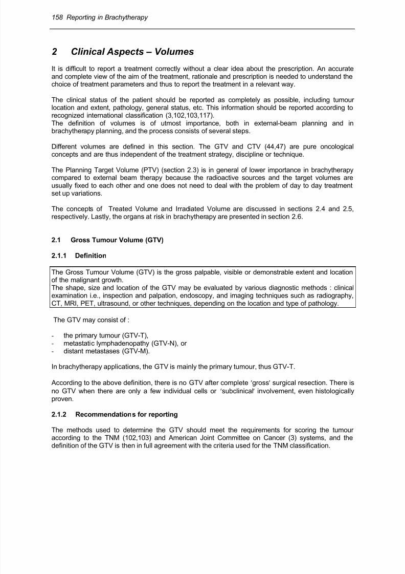
Fig 6.1 : The figure illustrates the superiority of MRI compared with CT for discrimination betweendifferent types of tissues for a patient with cervix carcinoma III AB. A: Transversal CT showing a large soft tissue mass at the level of the uterine cervix, infiltrating intoboth parametria. No discrimination between GTV and uterine tissue is possible.B: Transversal MRI showing a high signal intensity mass indicating macroscopic tumour infiltratinginto both parametria and into the left sacrouterine ligament. A clear distinction is possible fromnormal uterine tissue (arrows).C: Sagittal MRI showing a high signal intensity mass at the level of the cervix in the midsagittal planeextending mainly posteriorily with clear distinction from the uterine corpus (two contiguous sections
are presented in Fig A,B and C).
The GTV may appear to be different in size and shape, sometimes significantly so, depending onwhat examination technique is used for evaluation (e.g., palpation versus mammography for breasttumours, CT versus MRI for some brain tumours, CT versus MRI/ultrasound for prostate cancer).Therefore, the radiation oncologist should, in each case, indicate which method has been used forthe evaluation and delineation of the GTV. Figure 6.1 illustrates the specific contribution of MRI fordiscrimination between different types of tissues.
8/11/2019 Reporting in Brachytherapy
http://slidepdf.com/reader/full/reporting-in-brachytherapy 8/63
160 Reporting in Brachytherapy
A GTV may be confined to only part of an organ (e.g. T2a in prostate cancer), or involve a wholeorgan (e.g., T2b in prostate cancer, IB2 in cervix cancer). The GTV may or may not extend outsidethe normal borders of the organ tissue involved.For reporting, the GTV should be described in standard topographical or anatomical terms, e.g.“18mm x 12 mm x 20 mm tumour in the left lobe of the prostate adjacent to but not reaching thecapsule“, cT2a.
In many situations, a verbal description might be too cumbersome and, therefore, for the purpose ofdata recording and analysis, a classification system is needed. Several systems have been proposedfor coding the anatomical description, some of them are mentioned in ICRU Report 50 (44).
Careful identification of the GTV is as important in brachytherapy as in external beam therapy, for atleast three reasons: (1) accurate description of the GTV is needed for staging (e.g., TNM), (2)identification of the GTV is necessary to permit recording of tumor response in relation to dose andother relevant factors, which may be used (carefully) as a prognostic factor. (3) an adequate dosemust be delivered to all parts of the GTV to obtain local tumour control in radical treatments.
2.2 Clinical Target Volume (CTV)
2.2.1 Definition
The CTV is the volume which contains the „gross“ and „subclinical“ disease.Clinically, it thus contains the GTV and a „safety margin” around the GTV (CTV-T) to take intoaccount (probable) subclinical involvement.The CTV may also include other anatomical areas, e.g., regional lymph nodes (CTV-N) or othertissues with suspected (or proven) subclinical involvement (CTV-M).
“Subclinical involvement“ may consist of individual malignant cells, small cell clusters, or micro-extensions, which cannot be detected during staging procedures by the methods mentioned above.
The cell density is high in the GTV (typically 106/mm
3); it decreases in the safety margin from the
edge of the GTV towards the periphery of the CTV. The different parts of the CTV thus have to betreated at adequate dose levels (and time-dose patterns) to achieve the aim of therapy, either cure orpalliation.
If the GTV has been removed by radical surgery, and radiotherapy is needed to residual tissue closeto the site of the removed GTV, this volume is also usually designated as CTV-T (e.g., in breast-conserving procedures).
Delineation of a CTV requires consideration of factors such as the local invasive capacity of thetumor and its potential to spread, for example, to regional lymph nodes (based e.g. on histology).
The definition of CTV boundaries requires a clinical decision (31,62). In some cases, this decision isbased on probability evaluation (when data are available), but it often implies an arbitrary choice
(e.g., endovascular brachytherapy (86)). The final decision rests on the clinical experience and judgement of the radiation oncologist.
2.2.2 Recommendations for reporting
The CTV (like the GTV) is a purely clinical-anatomical concept : it should therefore be described interms of the patient’s anatomy and the tumor extent, independently of any dose distribution. As a
8/11/2019 Reporting in Brachytherapy
http://slidepdf.com/reader/full/reporting-in-brachytherapy 9/63
Reporting in Brachytherapy 161
minimum recommendation, its physical dimensions should be reported in terms of maximumdiameters, in mm (or cm) in three orthogonal directions. The CTV must be defined in plaintopographic terms and/or according to a code which conforms with the recommendations for theGTV.
2.2.3 GTV and CTV: pure oncological concepts
It must be stressed that the GTV and CTV are purely oncological concepts, and are thusindependent of the therapeutic approach. In particular, they are not specific to the discipline ofradiation therapy. For example, in surgery, a safety margin is taken around the GTV according toclinical judgement, and this implies the use of the same CTV concept as in radiation therapy. Inbrachytherapy, as in external-beam therapy, volumes to be irradiated are defined, and thus the sameconcept of CTV is applied. Furthermore, the CTV concept can be applied to other modalities, e.g.,regional chemotherapy, hyperthermia, and photocoagulation.
The definitions of GTV and CTV in brachytherapy are thus identical to the definitions given forexternal-beam radiotherapy in ICRU Report 50 (44) and Supplement to Report 50, ICRU Report 62(47).
2.3 Planning Target Volume (PTV)
2.3.1 Definition
The PTV is a geometrical concept used for treatment planning.The aim is to ensure that the prescribed dose is actually absorbed in the whole CTV, taking intoconsideration the net effect of all the possible variations of position of the CTV relative to theirradiation source.In external beam therapy, the PTV is defined to enable selection of appropriate beam sizes andbeam arrangements. In brachytherapy, the PTV is defined to select appropriate source arrangement,positioning and/or movement control. The dose distribution to the PTV has to be considered as
representative of the dose distribution to the CTV.
2.3.2 PTV in external beam- and in brachytherapy
In external-beam therapy, to ensure that all tissues included in the CTV receive the prescribed dose,one has, in principle, to plan to irradiate a volume geometrically larger than the CTV : the PTV. Theadditional safety margin results from a number of factors :
(1)-the Internal Margin is intended to take into account the expected physiological movements (e.g.,respiration) and variations in size, shape, and position (e.g., stomach, bladder, rectum) of the CTV;
(2)-the Set-Up Margin is intended to take into account all variations and uncertainties in beam
geometry and patient-beam positioning.
The situation is quite different in brachytherapy because the source (or source applicator) is, ingeneral, fixed to the target volume. Therefore, in brachytherapy, the PTV is often considered to beidentical to the CTV.
There are however exceptions. For instance, in intraluminal brachytherapy, a safety margin is addedaround the CTV to compensate for inaccuracies or uncertainties in the position of the radioactive

8/11/2019 Reporting in Brachytherapy
http://slidepdf.com/reader/full/reporting-in-brachytherapy 10/63
162 Reporting in Brachytherapy
source(s) relative to the patient’s organ. Such inaccuracies can be due to displacement of the source(in the longitudinal or radial direction), patient motion, etc.
The width of this safety margin should, ideally, be based on systematic evaluation of theuncertainties. It may differ according to the organ being treated, the clinical target volume and alsothe type of applicator and technical devices used. With some techniques, there are uncertaintiesabout consistency of source position (moving sources, fractionated techniques) or alteration ofsource or applicator position (intracavitary applications, permanent implants) during the application.
Remarks:
1°) In external therapy, the two steps (localisation of CTV and treatment planning) can always bedissociated and therefore checked separately. However, in interstitial therapy, a better evaluation ofthe tumour extent (and regression after external beam therapy) may often be obtained by theclinician at the time of application (due e.g. to general anaesthesia). The final decision on the CTVmay then be modified.
2°) Due to the high density of the cancer cells in the GTV (about 106/mm
3), a high irradiation dose
must always be delivered to all parts of the GTV in radical treatments.
3°) A CTV may be treated by 2 (or more) PTVs (e.g., external and brachytherapy). In particular,because the cancer cell density is higher in the GTV compared to tissues with only subclinicaldisease, different dose levels may be prescribed and thus several PTVs be identified.
This is the case, for example, in ‘boost‘ therapy where the ‘higher-dose‘ volume (often containing theGTV) is located inside the ‘lower-dose‘ volume. For example, 50 Gy may be prescribed to a largePTV followed by an additional 35 Gy to a smaller PTV („boost“) corresponding to the GTV only.These two PTVs may be referred to as PTV-50 and PTV-85, respectively.
Another example is the treatment of cervix cancer where the central part of the PTV is mainly treatedwith high-dose brachytherapy and the lateral extensions by external beam and a lower dose
contribution from brachytherapy.
2.4 Treated Volume
The treated volume is the volume of tissue which, according to the implant as actually achieved,receives a dose at least equal to the dose selected and specified by the radiation oncologist as beingappropriate to achieve the goal of the treatment.
The Treated Volume is thus encompassed by an isodose surface corresponding to that dose level,which is the Minimum Target Dose (section 6.3.2, 7.4.3). This isodose surface should ideally matchthe PTV as closely as possible, it should entirely encompass the CTV/PTV, but may be largerdepending on the available sources and source arrangement. The Treated Volume (and the PTV)
thus depends on the irradiation technique.
2.5 Irradiated Volume
The Irradiated Volume is the tissue volume, larger than the Treated Volume, which receives a doseconsidered to be significant in relation to normal tissue tolerance.
8/11/2019 Reporting in Brachytherapy
http://slidepdf.com/reader/full/reporting-in-brachytherapy 11/63
Reporting in Brachytherapy 163
The dose considered to be significant must be clearly stated:
-in absolute dose value (in Gy),-as a percentage (e.g., 50%) of the prescribed dose or of the dose at a reference point.
The dimensions of the Irradiated Volume should be reported. The Irradiated Volume depends on thetechnique and may be used as an optimization parameter.
2.6 Organs At Risk (OAR)
2.6.1 Definition
Organs At Risk (OAR) (“critical normal structures”) are normal structures that, because of theirradiosensitivity and/or their location close to the target volume, may significantly influence thetreatment planning and/or the prescribed dose level (ICRU Report 62) (47).
The probability of side effects depends on several factors of the irradiation : dose level, fraction size
and dose rate, irradiated volume, but also probably a complex dose-volume combination(7,18,23,73,77,78,84,85,87).
2.6.2 PTV and Organs At Risk
In brachytherapy, as indicated in ICRU Report 50 (44) for external-beam therapy, when delineatingthe PTV, a compromise is always necessary due to adjacent radiosensitive normal tissues (Organs At Risk), as well as to other factors such as the general condition of the patient.
Delineation of the PTV which requires judgement and experience is the responsibility of the radiationoncologist.
For example, in brachytherapy for cervix cancer, the PTV is limited in the AP direction by thepresence of the bladder and the rectum. The treatment is frequently planned to the maximumtolerable dose to these organs at risk.
3 Reporting the Technical Aspects of the BrachytherapyTreatment
3.1 Description of the radioactive sources
The description of the sources should include complete information on:
• radionuclide;• type of source, i.e., wire, needle, tube, seeds, seed ribbon, hairpin, radioactive stent, liquid or gas
filled balloon, etc;
• physical characteristics of the sources: dimensions (core dimensions and outer dimensions),chemical composition, filtration (if relevant) ;
• length of each source line (if line sources are used): physical and active length.
8/11/2019 Reporting in Brachytherapy
http://slidepdf.com/reader/full/reporting-in-brachytherapy 12/63
164 Reporting in Brachytherapy
Active source length
The active source length is defined as the distance from the most proximal to most distal end of theradioactive material contained in the source line: e.g., (physical) length of wire, seed train, ribbonsource. For a moving source, the length is defined as the distance between its extreme positions.
• strength (activity) of the sources, specified according to the recommendations of section 4.• distribution of the activity within the source(s) (uniform or differential loading, etc.) (10,22,58).
3.2 Source pattern
● number of sources or source lines;● separation between source lines and between planes, or separation between the guides, if a
single moving source is used;
• geometrical pattern formed by the sources (e.g., triangles, squares), for interstitial implants orutero-vaginal source spacing, where relevant;
• the surfaces in which the implant lies, i.e., planes or curved surfaces;
• whether crossing sources are placed at one or more ends of a group of linear sources.
3.3 Applicator
• catheter, material of the inactive vector used to carry the radioactive sources (e.g., flexible orrigid);
• dimensions (diameter and length);
• whether rigid templates are used at one or both ends;
• centering device for the catheter (e.g., for intrabronchial or endovascular applications);
• fixation;
• shielding (high atomic number material, e.g., for the rectum in cervix treatment, or the mandibulain lip or oral cavity interstitial applications;
• for cervix treatment, fully rigid applicator (or not), consequently fixed known geometry (or not) ofthe complete applicator device;
• rigid uterine source with fixed curvature (or not) ;
• connection between vaginal and uterine applicators, i.e., fixed, loose (semi-fixed), free ;● type of vaginal sources: ovoids (size and separation), line sources (number and orientation),
special sources (box, ring, mould, etc.).
3.4 Type of afterloading and source movement
● manual afterloading;● remote afterloading;
(sufficient relevant information should be given on the mechanical system of afterloading)
(1,36,49,50,110,112,113);● stepping source;● oscillating source
(an accurate description of the source movements is necessary to derive the time-dose patternat the different points in the PTV or organs at risk, see section 5, p. 168).
NB: Description of the source(s), applicator and technique is facilitated when the types/models havebeen published. The complete reference of the publication is then often sufficient. When appropriate,

8/11/2019 Reporting in Brachytherapy
http://slidepdf.com/reader/full/reporting-in-brachytherapy 13/63
Reporting in Brachytherapy 165
the manufacturer should be mentioned. However, any variation between the published conditionsand that actually used should be mentioned. If new types of sources, applicators or techniques areused, a full description is needed.
3.5 The “Systems“
The term “system” (ICRU, Report 38,(43)) denotes a set of rules taking into account the sourcestrengths, geometry and method of application in order to obtain suitable dose distributions over thevolume(s) to be treated.For reporting, the system includes recommendations for specifying the application and possibly, as inthe Manchester System, for calculating the dose rate (or the dose) at specific points.
The “historical“ systems mentioned in the present chapter were developed in a period wherecomputer treatment planning and dose computations were not yet available.
In brachytherapy applications, a “system“ ensures safety insofar as it implies application rules andis based on clinical experience. If a system is followed, it must be followed for (1) prescription, (2)application of the sources in space and time and (3) reporting.
If a standard system has been followed, it must be specified and this facilitates reporting. If it is notthe case, the source pattern should be described completely and unambiguously.
Development of computers and easy availability of complete dose distribution (which is per se abenefit) tends to increase the use of “no system“ applications.
4 Specification of the Source “Strength” (Intensity) inBrachytherapy
A clear distinction should be made between specification of the sources, dealt with in this section,
and specification of the doses to the patient organs or tissues, dealt with in sections 6, 7 and 8.
4.1 Reference Air Kerma Rate (RAKR)
As a general recommendation (ICRU, Reports 38 and 58 (43,45)), the “strength” (intensity) of photonemitting radioactive sources for brachytherapy should always be specified in terms of the quantity”Reference Air Kerma Rate“ (RAKR).
The problem of specification of sources in brachytheray is an important one. A new concept hasbeen introduced with the aim of replacing the activity (contained or ”apparent“) in a source by the“output“ from the source. This concept has been discussed by several authors, and the quantityReference Air Kerma Rate has been increasingly adopted by different organizations and
commissions (2,4,9,11,15,17,21,41,60,61,69,71,72,98,114).
4.1.1 Definition
The Reference Air Kerma Rate (RAKR) of a brachytherapy source is the air-kerma rate, in vacuo, ata reference distance of 1 meter from the source centre, on its transverse axis due to photons ofenergy greater than δ.
8/11/2019 Reporting in Brachytherapy
http://slidepdf.com/reader/full/reporting-in-brachytherapy 14/63
166 Reporting in Brachytherapy
4.1.2 Units
The quantity reference air kerma rate is expressed in Gy s-1
at one meter, or a multiple of this unit (in
a convenient way, e.g. for low dose-rate brachytherapy, in microgray per hour, µGy h-1
, at 1 m).
4.1.3 Energy cut-off, δ
The energy cut-off is intended to exclude low-energy or contaminant photons (e.g., characteristic xrays originating in the outer layers of steel or titanium source cladding) that can significantly increaseRAKR without contributing significantly to absorbed dose at distances greater than about 1 mm intissue.
4.1.4 Air kerma rate constant Γδ
The relation between RAKR of a given source and other quantities used to specify the radioactive
sources in brachytherapy is based on the physical quantity „air kerma rate constant“, δ (14,45,46).
For a gamma emitting radionuclides, Γδ is the kerma rate, for a point source, at a reference distanceof one meter, per unit activity, due to photons of energy greater than δ, in the „in vacuo“ conditionsdefined above.
For the gamma energies emitted by the radionuclides used in brachytherapy, one may consider thatthe numerical values for dose and kerma are equal.
Γδ is expressed in Gy per second at one meter, or multiples. Some numerical values are given inTable 2.2 in Chapter 2 / p. 26 [ICRU, Report 58 (45)].
4.2 Total Reference Air Kerma (TRAK)
4.2.1 Definition
The Total Reference Air Kerma (TRAK) is the sum of the products of the Reference Air Kerma Rateand the irradiation time for each source.
4.2.2 Practical application of the TRAK
The TRAK is an important quantity which should be reported for all brachytherapy applications, forthe following reasons :
(1) It is an unambiguous quantity that is simple to calculate (on condition that the strengths of thesources are expressed in RAKR (4.1).
(2) The conversion of the quantity mg.h to the TRAK is easy and straightforward : 1 mg.h
radium equivalent (0.5 mm Pt filtration) corresponds to 7.2 µGy at 1 m.

8/11/2019 Reporting in Brachytherapy
http://slidepdf.com/reader/full/reporting-in-brachytherapy 15/63
Reporting in Brachytherapy 167
The TRAK, corresponds in terms of the “modern“ SI units, to the „historical“ quantity mg.h. Itimplies that the extensive and long standing clinical experience of the use of mg.h can beexploited for today’s protocols and studies.
(3) The doses to all organs, and thus the integral dose to the patient, are directly proportional to theTRAK.
(4) In addition, the use of TRAK provides, as a first approximation, an indication of the absorbeddoses delivered during treatment at distances from the sources down to 20 - 10 cm (i.e., in thepelvis or abdomen). The dose at 10 cm from the centre of the sources is roughly 100 timeshigher than the TRAK. It is indeed easy to verify that when the distance of a point P from thecentre of the volume (C) occupied by the sources is larger than 2.5 times the largest dimensionof that volume, the dose rate obtained at P from the actual distribution of the sources differs byless that 4% from that obtained by assuming that all the sources are located at C (20). However,the TRAK does not allow one to derive, even approximately, the absorbed dose in the immediatevicinity of the sources (i.e., in the tumour or target volume).
(5) The TRAK, or the sum of the RAKR of all sources, can serve as a useful index for radiationprotection of the personnel and nursing staff in charge of the patient (kerma -or dose- rate at 1
meter from the patient, neglecting, as a first approximation, the attenuation and scatteringphenomena).
4.3 Additional specification of photon sources used for intraluminal applications
In addition to the RAKR and TRAK, for photon sources used in intraluminal brachytherapy, thefollowing recommendation is made (48).
For intraluminal brachytherapy applications, it is also recommended to report the dose rate (anddose) at 10 mm from the source axis at the centre of the source (section 7, p. 181).
This recommendation is partly justified by the fact that several authors have reported their data using
the above source specification.
4.4 Specification of beta-ray sources used for endovascular brachytherapy
The following recommendation is made for beta-ray sources used in intravascular brachytherapy(48).
The intensity of the beta-ray emitting sources should be specified in terms of the Reference Absorbed Dose Rate at a distance of 2 mm from the source centre (axis).
NB :
As can be seen from the recommendations above, all sources for brachytherapy applications arespecified in terms of their “output” (dose rate) at reference distances and/or in different conditions.The quantity “activity” is used only for regulatory and protection purposes.
8/11/2019 Reporting in Brachytherapy
http://slidepdf.com/reader/full/reporting-in-brachytherapy 16/63
168 Reporting in Brachytherapy
5 Reporting the Time-Dose Pattern in Brachytherapy
5.1 Description of the time-dose pattern
The description of the time-dose pattern should include the type of irradiation with the necessary dataon treatment and irradiation times (49). The information on dose and time should provide the
necessary data to calculate instantaneous and average dose rates.
• The overall treatment time should always be recorded.
• Continuous irradiation: dose rate.
• Non-continuous irradiation: the total irradiation time should be recorded.
• Fractionated and pulsed irradiation: the fraction size and irradiation time of each fraction, theinterval between fractions, and the overall treatment time should be recorded.
• When the irradiation times of the different sources are not identical, they should be recorded.
For moving sources:
• Stepping sources: step size, dwell location and dwell time should be recorded.Variation of the dwell times of a stepping source can be used to manipulate the dose distribution.This can be achieved either by manual adaptation of the source positions in relation to the TargetVolume, or by a computer optimisation programme. If such a dose optimization is applied, thisshould be specified (e.g., optimization at dose points defined in the implant, or geometricaloptimization (52)).
• Oscillating sources: speed in different sections of the vectors should be recorded.
5.2 Biologically weighted dose
For comparing applications performed using different dose rates, doses per fraction or otherdifferences in time-dose patterns, weighting factors, Wrate , must be introduced. The product of the(physical) absorbed dose, D, by these weighting factors, W
rate , is the biologically weighted dose,
Drate , for dose rate, dose per fraction or other differences in time-dose pattern.
When evaluating the “radiobiological equivalence” between treatments performed with different time-dose patterns, the radiobiological model used (e.g., α/β, repair function, ...) as well as the numericalvalues of the parameters applied, must be indicated. In addition, the conditions for evaluation ofradiobiological equivalence must be stated (e.g., late or early effects, type of tissue, dose and doserate range, etc.) (35,56,66,113,115,116).
For reporting, the biologically weighted dose Drate alone cannot be given, but the (physical) absorbeddose and the complete time-dose pattern should be given together with the weighted dose. This willavoid confusion when comparing treatments and will allow, eventually, re-evaluation of“radiobiological equivalence” when new and better radiobiological data becomes available.
An important issue when evaluating “radiobiological equivalence” is the selection of the referencedose rate or time-dose pattern. As a general rule, and unless otherwise stated, “historical” continuouslow dose rate irradiation is taken as the reference (i.e., typically with radium, 60 Gy in 6 days orabout 0.5 Gy per hour, at the specification point).
8/11/2019 Reporting in Brachytherapy
http://slidepdf.com/reader/full/reporting-in-brachytherapy 17/63
Reporting in Brachytherapy 169
At present, reliable and universally accepted methods of evaluating radiobiological equivalencebetween brachytherapy applications performed with different time-dose patterns are not available;great care must therefore be taken when comparing different treatment schedules.
6 Interstitial Therapy: Definition of Concepts, Doses and
Volumes for Reporting
6.1 Some “historical“ systems in interstitial therapy
Some historical systems are briefly recalled to facilitate interpretation of the definitions and conceptsdeveloped in this section.
6.1.1 The Paterson-Parker System
The Paterson-Parker System (Manchester System) was developed to deliver a reasonable doseuniformity (+/- 10 %) throughout a region implanted with radium needles (64,75,76).
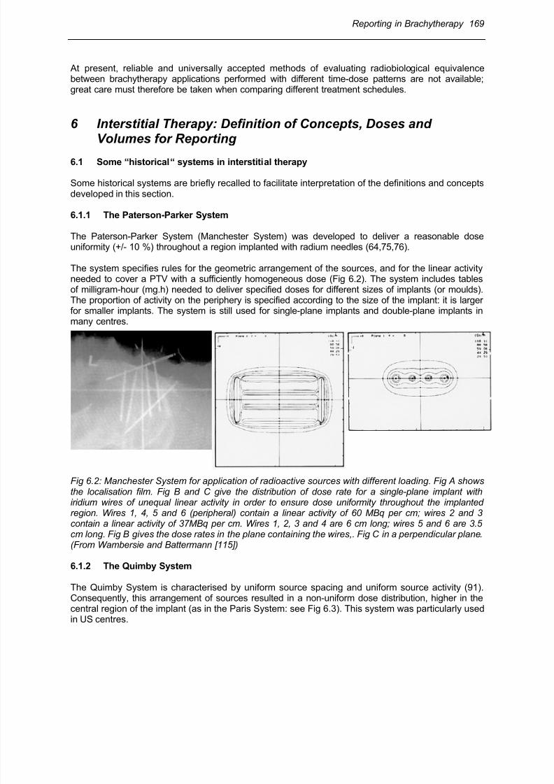
The system specifies rules for the geometric arrangement of the sources, and for the linear activityneeded to cover a PTV with a sufficiently homogeneous dose (Fig 6.2). The system includes tablesof milligram-hour (mg.h) needed to deliver specified doses for different sizes of implants (or moulds).The proportion of activity on the periphery is specified according to the size of the implant: it is largerfor smaller implants. The system is still used for single-plane implants and double-plane implants inmany centres.
Fig 6.2: Manchester System for application of radioactive sources with different loading. Fig A showsthe localisation film. Fig B and C give the distribution of dose rate for a single-plane implant withiridium wires of unequal linear activity in order to ensure dose uniformity throughout the implantedregion. Wires 1, 4, 5 and 6 (peripheral) contain a linear activity of 60 MBq per cm; wires 2 and 3contain a linear activity of 37MBq per cm. Wires 1, 2, 3 and 4 are 6 cm long; wires 5 and 6 are 3.5cm long. Fig B gives the dose rates in the plane containing the wires,. Fig C in a perpendicular plane.
(From Wambersie and Battermann [115])
6.1.2 The Quimby System
The Quimby System is characterised by uniform source spacing and uniform source activity (91).Consequently, this arrangement of sources resulted in a non-uniform dose distribution, higher in thecentral region of the implant (as in the Paris System: see Fig 6.3). This system was particularly usedin US centres.

8/11/2019 Reporting in Brachytherapy
http://slidepdf.com/reader/full/reporting-in-brachytherapy 18/63
170 Reporting in Brachytherapy
6.1.3 The Paris System
Fig 6.3 : Iridium-192 wire implant according to the Paris system (single-plane implant). The wires areof equal linear activity, parallel, and arranged in such a way that their centres are in the same plane perpendicular to the direction of the wires (i.e. the central plane, see Fig 6.4).(From Wambersie and Battermann [115])
Fig 6.4: The central plane. In an implant where the source lines are rectilineal, parallel, and of equallength, the central plane is perpendicular to the direction of the source lines and passes throughouttheir centres. The Mean Central Dose (Dm ) is the mean of the local minimum doses Di (I = A, B …) inthe plateau region. (A) A single plane implant; (B) a two-plane implant; (C) an actual single-planeimplant where sources are not rectilinear: the central plane can be defined as in (A).(From ICRU Report 58 (45).
8/11/2019 Reporting in Brachytherapy
http://slidepdf.com/reader/full/reporting-in-brachytherapy 19/63
Reporting in Brachytherapy 171
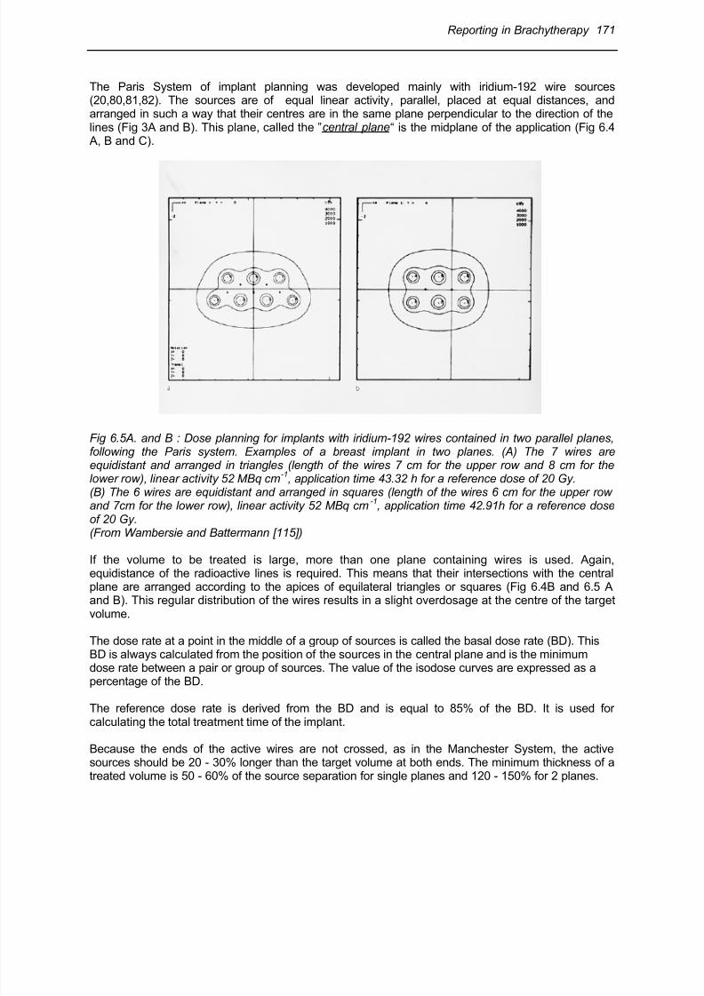
The Paris System of implant planning was developed mainly with iridium-192 wire sources(20,80,81,82). The sources are of equal linear activity, parallel, placed at equal distances, andarranged in such a way that their centres are in the same plane perpendicular to the direction of thelines (Fig 3A and B). This plane, called the ”central plane“ is the midplane of the application (Fig 6.4 A, B and C).
Fig 6.5A. and B : Dose planning for implants with iridium-192 wires contained in two parallel planes,following the Paris system. Examples of a breast implant in two planes. (A) The 7 wires areequidistant and arranged in triangles (length of the wires 7 cm for the upper row and 8 cm for thelower row), linear activity 52 MBq cm
-1, application time 43.32 h for a reference dose of 20 Gy.
(B) The 6 wires are equidistant and arranged in squares (length of the wires 6 cm for the upper rowand 7cm for the lower row), linear activity 52 MBq cm
-1, application time 42.91h for a reference dose
of 20 Gy.(From Wambersie and Battermann [115])
If the volume to be treated is large, more than one plane containing wires is used. Again,equidistance of the radioactive lines is required. This means that their intersections with the centralplane are arranged according to the apices of equilateral triangles or squares (Fig 6.4B and 6.5 Aand B). This regular distribution of the wires results in a slight overdosage at the centre of the targetvolume.
The dose rate at a point in the middle of a group of sources is called the basal dose rate (BD). ThisBD is always calculated from the position of the sources in the central plane and is the minimumdose rate between a pair or group of sources. The value of the isodose curves are expressed as apercentage of the BD.
The reference dose rate is derived from the BD and is equal to 85% of the BD. It is used forcalculating the total treatment time of the implant.
Because the ends of the active wires are not crossed, as in the Manchester System, the activesources should be 20 - 30% longer than the target volume at both ends. The minimum thickness of atreated volume is 50 - 60% of the source separation for single planes and 120 - 150% for 2 planes.
8/11/2019 Reporting in Brachytherapy
http://slidepdf.com/reader/full/reporting-in-brachytherapy 20/63
172 Reporting in Brachytherapy
6.1.4 Need for a common language
With the development of computer based dose calculation, there is more freedom for prescribing andperforming brachytherapy applications. It is therefore important that a common language is availableto report treatments and make exchange of information possible and reliable.
6.2 Dose distribution in interstitial therapy
6.2.1 General description
In interstitial therapy, the dose distribution is non-homogeneous and includes steep dose gradientsand regions of high dose surrounding each source. The doses (and the dose gradients) decreasewith the distance from the sources.
6.2.2 Local minimum doses
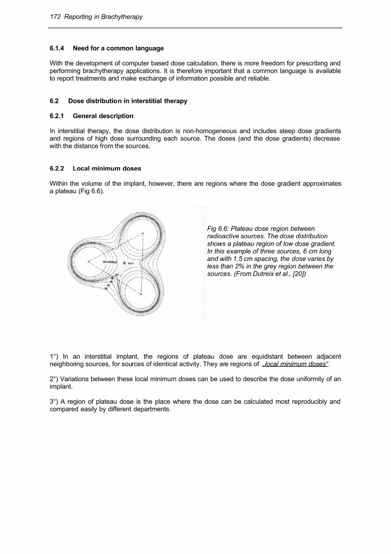
Within the volume of the implant, however, there are regions where the dose gradient approximates
a plateau (Fig 6.6).
Fig 6.6: Plateau dose region betweenradioactive sources. The dose distributionshows a plateau region of low dose gradient.In this example of three sources, 6 cm longand with 1.5 cm spacing, the dose varies byless than 2% in the grey region between thesources. (From Dutreix et al., [20])
1°) In an interstitial implant, the regions of plateau dose are equidistant between adjacentneighboring sources, for sources of identical activity. They are regions of „local minimum doses“ .
2°) Variations between these local minimum doses can be used to describe the dose uniformity of an
implant.
3°) A region of plateau dose is the place where the dose can be calculated most reproducibly andcompared easily by different departments.
8/11/2019 Reporting in Brachytherapy
http://slidepdf.com/reader/full/reporting-in-brachytherapy 21/63
Reporting in Brachytherapy 173
6.2.3 Central plane
To give the necessary information about the dose or dose rate distribution, isodose curves must becalculated in at least one chosen plane. If only one plane is used for isodose calculation, the “central plane of the implant “ should be chosen. In order to assess the dose distribution in other areas of theimplant, multiple planes for isodose calculation can be chosen, either parallel or perpendicular to thecentral plane.
In source patterns in which the source lines are straight, parallel, of equal length and with theircentres lying in a plane perpendicular to the direction of the source lines, this plane is defined as thecentral plane (see Fig 6.4A and B) (45).
In an actual implant, all source lines may not necessarily be straight, parallel, and of equal length. Insuch cases, the central plane should be chosen perpendicular to the main direction of the sourcelines and passing through the estimated centre of the implant (see Fig 6.4.C).
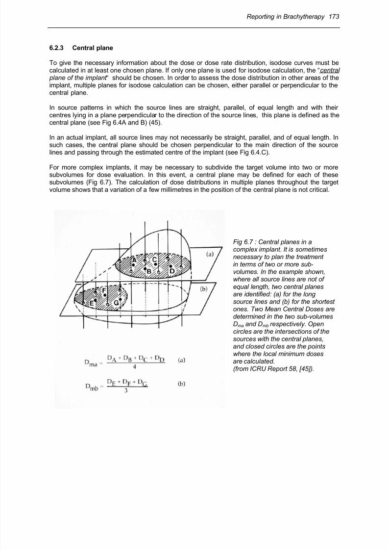
For more complex implants, it may be necessary to subdivide the target volume into two or moresubvolumes for dose evaluation. In this event, a central plane may be defined for each of thesesubvolumes (Fig 6.7). The calculation of dose distributions in multiple planes throughout the target
volume shows that a variation of a few millimetres in the position of the central plane is not critical.
Fig 6.7 : Central planes in acomplex implant. It is sometimesnecessary to plan the treatment in terms of two or more sub-volumes. In the example shown, where all source lines are not of
equal length, two central planes are identified: (a) for the long source lines and (b) for the shortest ones. Two Mean Central Doses are determined in the two sub-volumes Dma and Dmb respectively. Opencircles are the intersections of the sources with the central planes, and closed circles are the pointswhere the local minimum doses are calculated.(from ICRU Report 58, [45]).
8/11/2019 Reporting in Brachytherapy
http://slidepdf.com/reader/full/reporting-in-brachytherapy 22/63
174 Reporting in Brachytherapy
6.3 Reference points (dose levels) for reporting interstitial therapy
6.3.1 Mean Central Dose (MCD)
In interstitial therapy, the Mean Central Dose is defined as the arithmetic mean of the local minimum
doses between sources in the central plane (or in the central planes if there are more than one) (45).
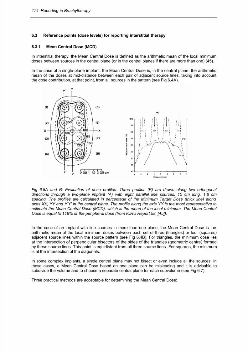
In the case of a single-plane implant, the Mean Central Dose is, in the central plane, the arithmeticmean of the doses at mid-distance between each pair of adjacent source lines, taking into accountthe dose contribution, at that point, from all sources in the pattern (see Fig 6.4A).
Fig 6.8A and B: Evaluation of dose profiles. Three profiles (B) are drawn along two orthogonaldirections through a two-plane implant (A) with eight parallel line sources, 10 cm long, 1.8 cmspacing. The profiles are calculated in percentage of the Minimum Target Dose (thick line) alongaxes XX, YY and Y’Y’ in the central plane. The profile along the axis YY is the most representative toestimate the Mean Central Dose (MCD), which is the mean of the local minimum. The Mean CentralDose is equal to 118% of the peripheral dose (from ICRU Report 58, [45]).
In the case of an implant with line sources in more than one plane, the Mean Central Dose is thearithmetic mean of the local minimum doses between each set of three (triangles) or four (squares)adjacent source lines within the source pattern (see Fig 6.4B). For triangles, the minimum dose liesat the intersection of perpendicular bisectors of the sides of the triangles (geometric centre) formed
by these source lines. This point is equidistant from all three source lines. For squares, the minimumis at the intersection of the diagonals.
In some complex implants, a single central plane may not bisect or even include all the sources. Inthese cases, a Mean Central Dose based on one plane can be misleading and it is advisable tosubdivide the volume and to choose a separate central plane for each subvolume (see Fig 6.7).
Three practical methods are acceptable for determining the Mean Central Dose:
8/11/2019 Reporting in Brachytherapy
http://slidepdf.com/reader/full/reporting-in-brachytherapy 23/63
Reporting in Brachytherapy 175
1. Evaluation of triangles: If parallel lines are used, one can identify triangles consisting of threeadjacent source lines for all the sources, so that the triangles formed constitute as many acutetriangles as possible. The intersection points of the perpendicular bisectors of each triangle aredetermined and the local minimum doses are calculated at each of these points. The mean ofthese local minimum doses is the Mean Central Dose. This method is the most precise whenparallel lines are used.
2. Evaluation of dose profiles: the dose profiles are calculated for one or more axes through thecenter of the implant passing through as many local minima as possible. The local minimumdoses are determined by inspection. The mean of these local minimum dose values is the MeanCentral Dose (Fig 6.8).
In a single surface implant performed following a curved surface, a profile may lead to anunderestimation of the Mean Central Dose.
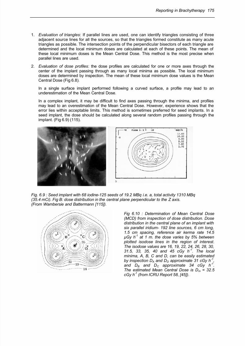
In a complex implant, it may be difficult to find axes passing through the minima, and profilesmay lead to an overestimation of the Mean Central Dose. However, experience shows that theerror lies within acceptable limits. This method is sometimes preferred for seed implants. In aseed implant, the dose should be calculated along several random profiles passing through the
implant. (Fig 6.9) (115).
Fig. 6.9 : Seed implant with 68 iodine-125 seeds of 19.2 MBq i.e. a, total activity 1310 MBq (35.4 mCi). Fig B: dose distribution in the central plane perpendicular to the Z axis.(From Wambersie and Battermann [115]).
Fig 6.10 : Determination of Mean Central Dose(MCD) from inspection of dose distribution. Dosedistribution in the central plane of an implant withsix parallel iridium- 192 line sources, 6 cm long,1.5 cm spacing, reference air kerma rate 14.5µGy h
-1 at 1 m. the dose varies by 5% between
plotted isodose lines in the region of interest.The isodose values are 16, 19, 22, 24, 26, 28, 30,31.5, 33, 35, 40 and 45 cGy h
-1. The local
minima, A, B, C and D, can be easily estimatedby inspection D A and DD approximate 31 cGy h
-1,
and DB and DC approximate 34 cGy h-1
.The estimated Mean Central Dose is Dm = 32.5cGy h
-1 (from ICRU Report 58, [45]).
8/11/2019 Reporting in Brachytherapy
http://slidepdf.com/reader/full/reporting-in-brachytherapy 24/63
176 Reporting in Brachytherapy
3. Inspection of dose distribution: the dose distribution is plotted in the central plane. With isodoselines varying by 5% (at most 10%) of the local dose in the central region, the local minima can bedetermined by inspection. The mean of these local minima is the Mean Central Dose (Fig 6.10).This method is often preferred for complex implants with line sources.
6.3.2 Minimum Target Dose
The Minimum Target Dose is the dose selected and specified by the radiation oncologist asadequate to treat the PTV. It corresponds to the prescribed dose in many instances. It is related tothe source arrangement and is the dose delivered at the periphery of the PTV. The application isplanned in such a way that all points of the PTV receive a dose (at least) equal to the MinimumTarget Dose.
The Minimum Target Dose is known in some American centers as the ‘minimum peripheral dose‘(19). It is equal to about 90% of the prescribed dose in the Manchester System for interstitial therapy.It is known as the ‘reference dose‘ in the Paris System, where it is equal to 85% of the Mean CentralDose (MCD).
6.4 Volumes for reporting in interstitial therapy
6.4.1 Treated Volume
As defined in section 2.4, the Treated Volume is the tissue volume that, based on the actual implant,receives at least a dose selected and specified by the radiation oncologist as appropriate to achievethe purpose of the treatment (e.g., tumour eradication or palliation).
Following the definition of the Minimum Target Dose (see above), the Treated Volume isencompassed by an isodose surface, the value of which is the Minimum Target Dose. The TreatedVolume should, in principle, entirely encompass the CTV (however, this may not necessarily alwaysbe the case).
6.4.2 High-dose regions
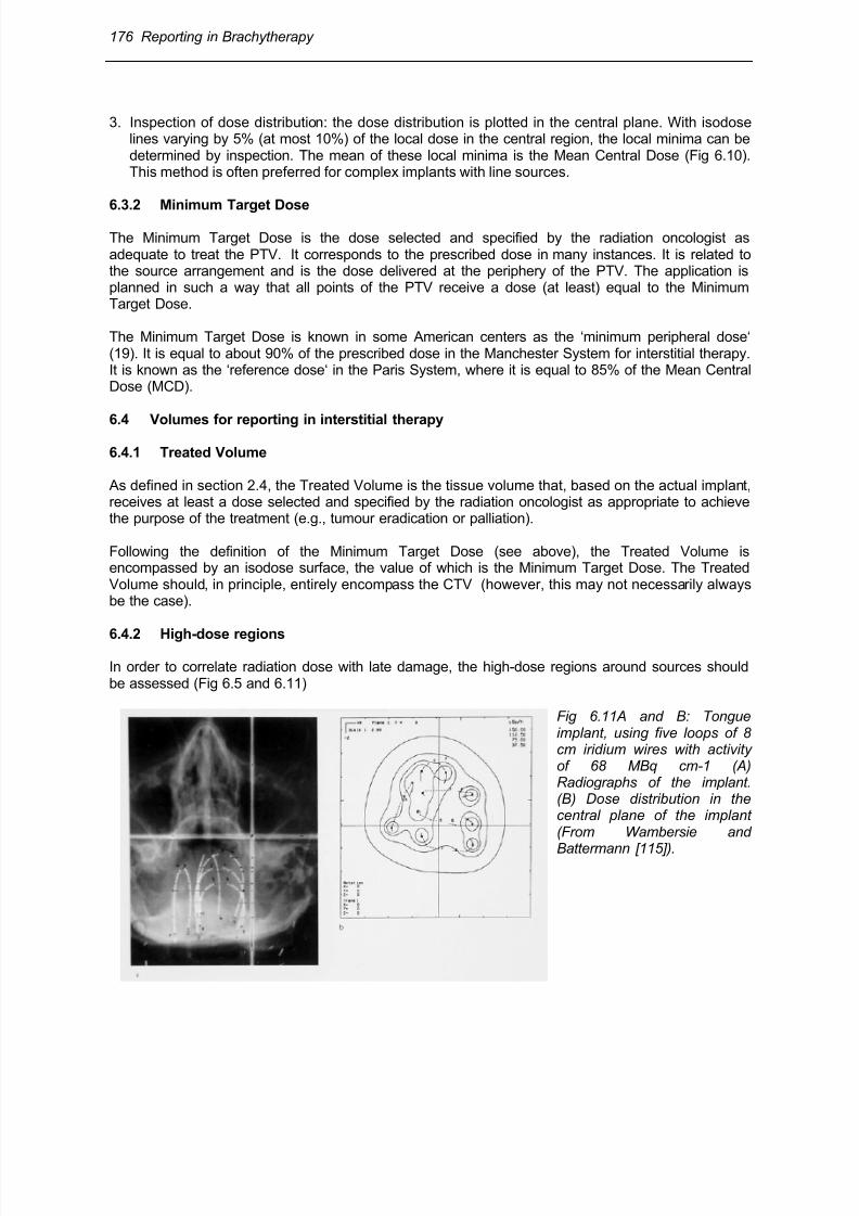
In order to correlate radiation dose with late damage, the high-dose regions around sources shouldbe assessed (Fig 6.5 and 6.11)
Fig 6.11A and B: Tongueimplant, using five loops of 8cm iridium wires with activityof 68 MBq cm-1 (A)Radiographs of the implant.(B) Dose distribution in thecentral plane of the implant(From Wambersie and
Battermann [115]).
8/11/2019 Reporting in Brachytherapy
http://slidepdf.com/reader/full/reporting-in-brachytherapy 25/63
Reporting in Brachytherapy 177
There will inevitably be a high-dose zone around each source. Although this zone is often small andwell tolerated, the exact tolerance dose and volume for interstitial therapy are not known yet.However, for intercomparison, there must be agreement on how to describe the high-dose volumes. A dose of approximately 100 Gy is likely to be significant in determining late effects. In those patientswho receive 50 - 60 Gy as Minimum Target Dose or 60 - 70 Gy as Mean Central Dose (MCD), 100Gy corresponds approximately to 150% of the MCD. It is therefore recommended in ICRU-Report 58(45) that the size of the region receiving more than 150% of the MCD should be reported.
The high-dose region should be defined as that encompassed by the isodose corresponding to 150%of the Mean Central Dose (MCD) around the sources in any plane parallel to the central plane wherea high-dose region is suspected. The maximum dimensions of all regions, in all planes calculated,should be reported.
6.4.3 Low-dose regions
A low-dose region is defined as a region, within the CTV, where the dose is less than 90% of theprescribed dose. The maximum dimension of the low-dose region in any plane calculated should bereported.
In implants for which the CTV is included within the Minimum Target Dose isodose, the occurrence ofa low-dose region is exceptional. If the CTV is not covered by the Minimum Target Dose isodose,there will be low-dose regions due to geographical miss. Low-dose regions should be reported inorder to correlate the local recurrence rate with the dose distribution.
6.4.4 Reference Volume
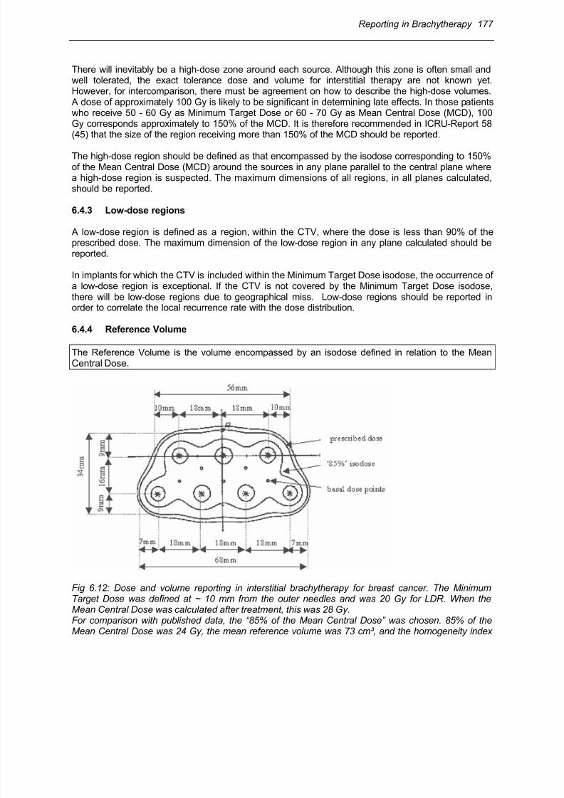
The Reference Volume is the volume encompassed by an isodose defined in relation to the MeanCentral Dose.
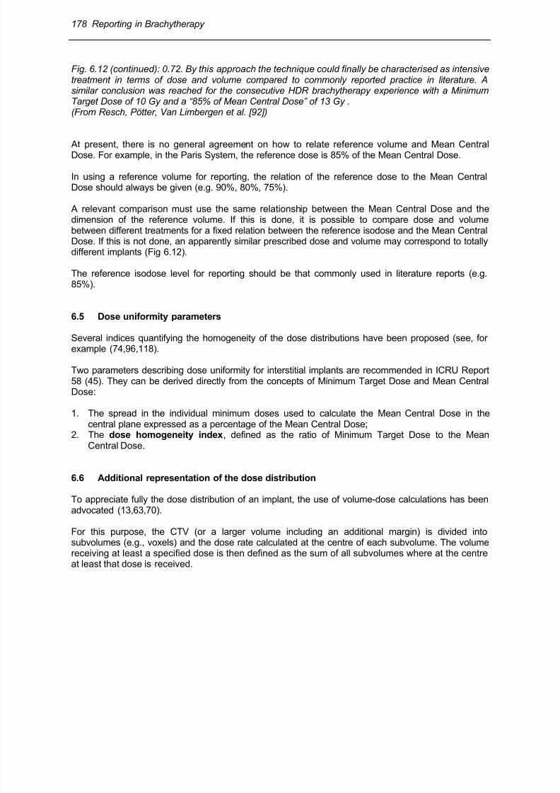
Fig 6.12: Dose and volume reporting in interstitial brachytherapy for breast cancer. The MinimumTarget Dose was defined at ~ 10 mm from the outer needles and was 20 Gy for LDR. When theMean Central Dose was calculated after treatment, this was 28 Gy.For comparison with published data, the “85% of the Mean Central Dose” was chosen. 85% of theMean Central Dose was 24 Gy, the mean reference volume was 73 cm³, and the homogeneity index
8/11/2019 Reporting in Brachytherapy
http://slidepdf.com/reader/full/reporting-in-brachytherapy 26/63
178 Reporting in Brachytherapy
Fig. 6.12 (continued): 0.72. By this approach the technique could finally be characterised as intensivetreatment in terms of dose and volume compared to commonly reported practice in literature. Asimilar conclusion was reached for the consecutive HDR brachytherapy experience with a MinimumTarget Dose of 10 Gy and a “85% of Mean Central Dose” of 13 Gy .(From Resch, Pötter, Van Limbergen et al. [92])
At present, there is no general agreement on how to relate reference volume and Mean CentralDose. For example, in the Paris System, the reference dose is 85% of the Mean Central Dose.
In using a reference volume for reporting, the relation of the reference dose to the Mean CentralDose should always be given (e.g. 90%, 80%, 75%).
A relevant comparison must use the same relationship between the Mean Central Dose and thedimension of the reference volume. If this is done, it is possible to compare dose and volumebetween different treatments for a fixed relation between the reference isodose and the Mean CentralDose. If this is not done, an apparently similar prescribed dose and volume may correspond to totallydifferent implants (Fig 6.12).
The reference isodose level for reporting should be that commonly used in literature reports (e.g.85%).
6.5 Dose uniformity parameters
Several indices quantifying the homogeneity of the dose distributions have been proposed (see, forexample (74,96,118).
Two parameters describing dose uniformity for interstitial implants are recommended in ICRU Report58 (45). They can be derived directly from the concepts of Minimum Target Dose and Mean CentralDose:
1. The spread in the individual minimum doses used to calculate the Mean Central Dose in thecentral plane expressed as a percentage of the Mean Central Dose;2. The dose homogeneity index, defined as the ratio of Minimum Target Dose to the Mean
Central Dose.
6.6 Additional representation of the dose distribution
To appreciate fully the dose distribution of an implant, the use of volume-dose calculations has beenadvocated (13,63,70).
For this purpose, the CTV (or a larger volume including an additional margin) is divided intosubvolumes (e.g., voxels) and the dose rate calculated at the centre of each subvolume. The volume
receiving at least a specified dose is then defined as the sum of all subvolumes where at the centreat least that dose is received.
8/11/2019 Reporting in Brachytherapy
http://slidepdf.com/reader/full/reporting-in-brachytherapy 27/63
Reporting in Brachytherapy 179
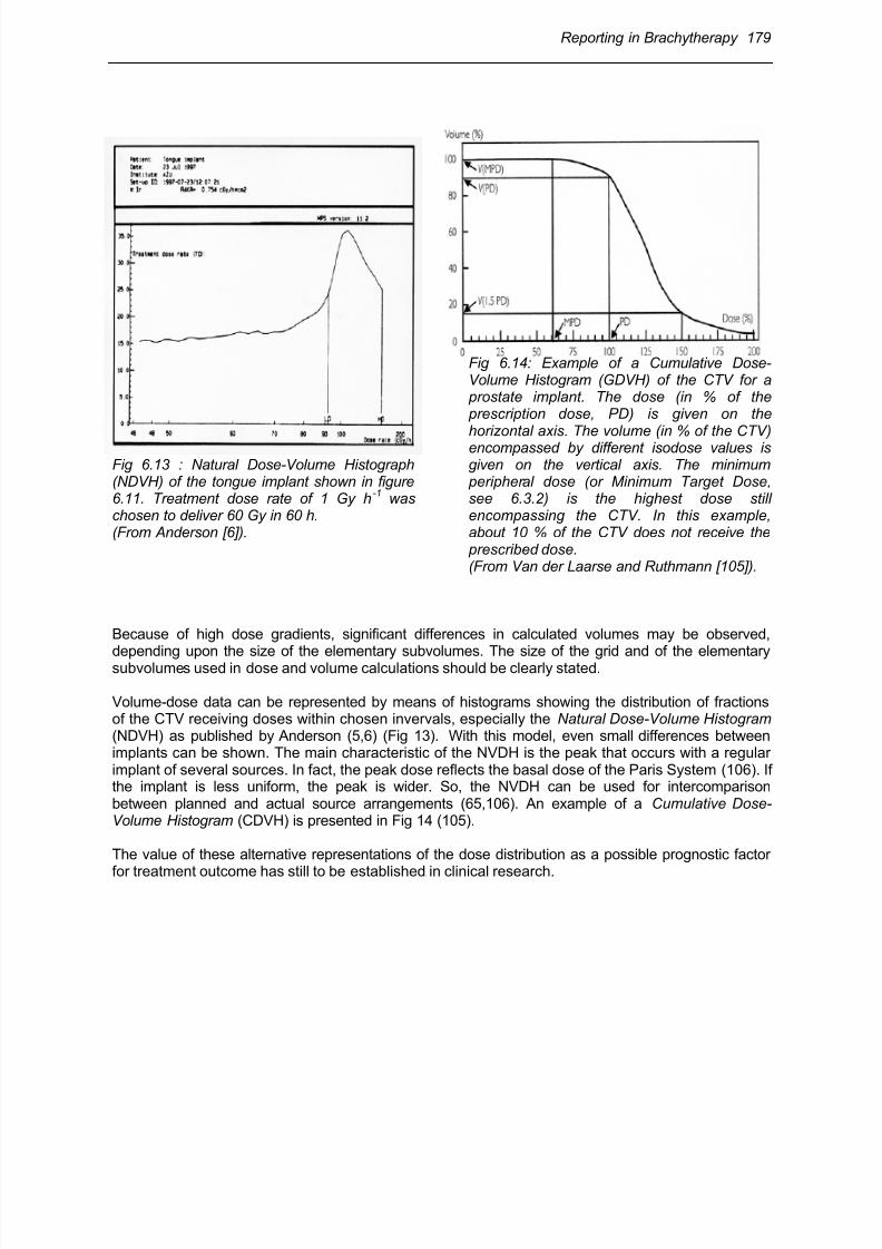
Fig 6.13 : Natural Dose-Volume Histograph(NDVH) of the tongue implant shown in figure6.11. Treatment dose rate of 1 Gy h
-1 was
chosen to deliver 60 Gy in 60 h.(From Anderson [6]).
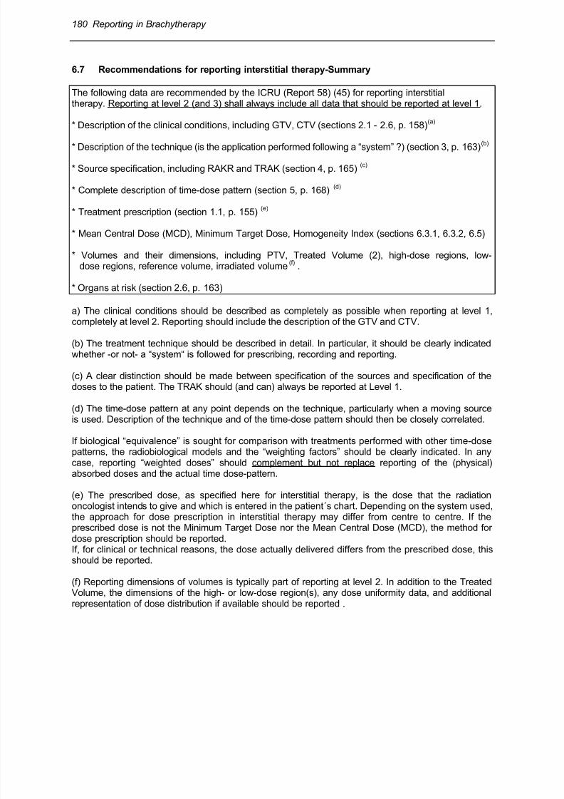
Fig 6.14: Example of a Cumulative Dose-Volume Histogram (GDVH) of the CTV for a prostate implant. The dose (in % of the prescription dose, PD) is given on the
horizontal axis. The volume (in % of the CTV)encompassed by different isodose values isgiven on the vertical axis. The minimum peripheral dose (or Minimum Target Dose,see 6.3.2) is the highest dose stillencompassing the CTV. In this example,about 10 % of the CTV does not receive the prescribed dose.(From Van der Laarse and Ruthmann [105]).
Because of high dose gradients, significant differences in calculated volumes may be observed,
depending upon the size of the elementary subvolumes. The size of the grid and of the elementarysubvolumes used in dose and volume calculations should be clearly stated.
Volume-dose data can be represented by means of histograms showing the distribution of fractionsof the CTV receiving doses within chosen invervals, especially the Natural Dose-Volume Histogram (NDVH) as published by Anderson (5,6) (Fig 13). With this model, even small differences betweenimplants can be shown. The main characteristic of the NVDH is the peak that occurs with a regularimplant of several sources. In fact, the peak dose reflects the basal dose of the Paris System (106). Ifthe implant is less uniform, the peak is wider. So, the NVDH can be used for intercomparisonbetween planned and actual source arrangements (65,106). An example of a Cumulative Dose-Volume Histogram (CDVH) is presented in Fig 14 (105).
The value of these alternative representations of the dose distribution as a possible prognostic factor
for treatment outcome has still to be established in clinical research.
8/11/2019 Reporting in Brachytherapy
http://slidepdf.com/reader/full/reporting-in-brachytherapy 28/63
180 Reporting in Brachytherapy
6.7 Recommendations for reporting interstitial therapy-Summary
The following data are recommended by the ICRU (Report 58) (45) for reporting interstitialtherapy. Reporting at level 2 (and 3) shall always include all data that should be reported at level 1.
* Description of the clinical conditions, including GTV, CTV (sections 2.1 - 2.6, p. 158)(a)
* Description of the technique (is the application performed following a “system” ?) (section 3, p. 163)(b)
* Source specification, including RAKR and TRAK (section 4, p. 165)(c)
* Complete description of time-dose pattern (section 5, p. 168)(d)
* Treatment prescription (section 1.1, p. 155)(e)
* Mean Central Dose (MCD), Minimum Target Dose, Homogeneity Index (sections 6.3.1, 6.3.2, 6.5)
* Volumes and their dimensions, including PTV, Treated Volume (2), high-dose regions, low-dose regions, reference volume, irradiated volume
(f) .
* Organs at risk (section 2.6, p. 163)
a) The clinical conditions should be described as completely as possible when reporting at level 1,completely at level 2. Reporting should include the description of the GTV and CTV.
(b) The treatment technique should be described in detail. In particular, it should be clearly indicatedwhether -or not- a “system“ is followed for prescribing, recording and reporting.
(c) A clear distinction should be made between specification of the sources and specification of thedoses to the patient. The TRAK should (and can) always be reported at Level 1.
(d) The time-dose pattern at any point depends on the technique, particularly when a moving source
is used. Description of the technique and of the time-dose pattern should then be closely correlated.
If biological “equivalence” is sought for comparison with treatments performed with other time-dosepatterns, the radiobiological models and the “weighting factors” should be clearly indicated. In anycase, reporting “weighted doses” should complement but not replace reporting of the (physical)absorbed doses and the actual time dose-pattern.
(e) The prescribed dose, as specified here for interstitial therapy, is the dose that the radiationoncologist intends to give and which is entered in the patient´s chart. Depending on the system used,the approach for dose prescription in interstitial therapy may differ from centre to centre. If theprescribed dose is not the Minimum Target Dose nor the Mean Central Dose (MCD), the method fordose prescription should be reported.If, for clinical or technical reasons, the dose actually delivered differs from the prescribed dose, this
should be reported.
(f) Reporting dimensions of volumes is typically part of reporting at level 2. In addition to the TreatedVolume, the dimensions of the high- or low-dose region(s), any dose uniformity data, and additionalrepresentation of dose distribution if available should be reported .
8/11/2019 Reporting in Brachytherapy
http://slidepdf.com/reader/full/reporting-in-brachytherapy 29/63
Reporting in Brachytherapy 181
7 Intraluminal Brachytherapy: Definition of Concepts, Dosesand Volumes for Reporting
7.1 Introduction
This section deals with recommendations for reporting intraluminal brachytherapy applications forbronchus, oesophagus, vagina, biliary duct tumours and endovascular brachytherapy.
Intraluminal applications consist of the insertion of one or several linear sources, contained inappropriate applicator devices, in natural cavities (or lumina). Other types of sources/applicatorsmay be used such as ovoids or moulds in the vagina. This technique allows delivery of high doses tothe CTV, while sparing organs at risk. The linear (or quasi linear) sources may be simulated byseveral point sources (seeds) or a moving source.
7.2 Dose distribution in intraluminal brachytherapy
In intraluminal brachytherapy, the radioactive material is inserted in the (anatomical) lumen, limitedby the mucosa, the usual site of origin of the tumour. Due to the (physical) inverse square law :
(a) the dose is decreasing dramatically as a function of distance to the linear source, and(b) the dose gradient is steepest close to the source and decreases with distance.
7.2.1 Dose at the luminal surface
The highest tissue dose is obtained at the level of the luminal surface; it depends on the applicatordiameter. The luminal surface dose is critically related to tumour control and the risk of complications.In contrast, the highest (physical) dose is within the applicator volume or in the lumen where it isobviously not clinically relevant.
7.2.2 Dose gradient
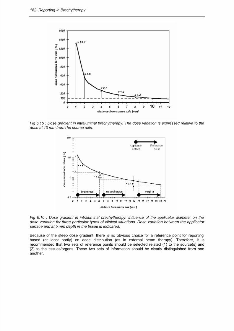
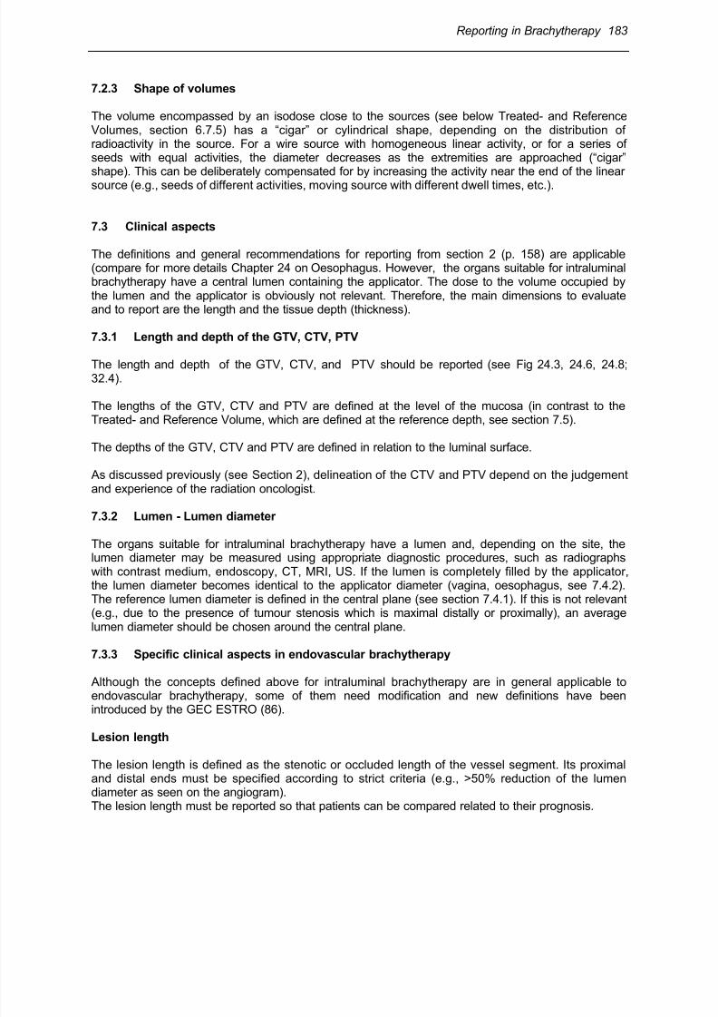
Dose inhomogeneity in the tissues, over a given radius (e.g., 5 mm), is high close to the source (i.e.,when a small diameter applicator is used); the dose becomes more homogeneous at a distance fromthe source (i.e., when a large diameter applicator is used). These situations are illustrated in figures15 and 16 for different diameter applicators . Dose homogeneity is better with a large applicator(when clinically possible); it can be expressed by comparing the dose variation between themucosal/tumour surface, the dose at the reference point in tissues and the external border of thePTV (see the definitions below).
8/11/2019 Reporting in Brachytherapy
http://slidepdf.com/reader/full/reporting-in-brachytherapy 30/63
182 Reporting in Brachytherapy
Fig 6.15 : Dose gradient in intraluminal brachytherapy. The dose variation is expressed relative to thedose at 10 mm from the source axis.
Fig 6.16 : Dose gradient in intraluminal brachytherapy. Influence of the applicator diameter on thedose variation for three particular types of clinical situations. Dose variation between the applicatorsurface and at 5 mm depth in the tissue is indicated.
Because of the steep dose gradient, there is no obvious choice for a reference point for reportingbased (at least partly) on dose distribution (as in external beam therapy). Therefore, it isrecommended that two sets of reference points should be selected related (1) to the source(s) and(2) to the tissues/organs. These two sets of information should be clearly distinguished from oneanother.
8/11/2019 Reporting in Brachytherapy
http://slidepdf.com/reader/full/reporting-in-brachytherapy 31/63
Reporting in Brachytherapy 183
7.2.3 Shape of volumes
The volume encompassed by an isodose close to the sources (see below Treated- and ReferenceVolumes, section 6.7.5) has a “cigar” or cylindrical shape, depending on the distribution ofradioactivity in the source. For a wire source with homogeneous linear activity, or for a series ofseeds with equal activities, the diameter decreases as the extremities are approached (“cigar”shape). This can be deliberately compensated for by increasing the activity near the end of the linearsource (e.g., seeds of different activities, moving source with different dwell times, etc.).
7.3 Clinical aspects
The definitions and general recommendations for reporting from section 2 (p. 158) are applicable(compare for more details Chapter 24 on Oesophagus. However, the organs suitable for intraluminalbrachytherapy have a central lumen containing the applicator. The dose to the volume occupied bythe lumen and the applicator is obviously not relevant. Therefore, the main dimensions to evaluateand to report are the length and the tissue depth (thickness).
7.3.1 Length and depth of the GTV, CTV, PTV
The length and depth of the GTV, CTV, and PTV should be reported (see Fig 24.3, 24.6, 24.8;32.4).
The lengths of the GTV, CTV and PTV are defined at the level of the mucosa (in contrast to theTreated- and Reference Volume, which are defined at the reference depth, see section 7.5).
The depths of the GTV, CTV and PTV are defined in relation to the luminal surface.
As discussed previously (see Section 2), delineation of the CTV and PTV depend on the judgementand experience of the radiation oncologist.
7.3.2 Lumen - Lumen diameter
The organs suitable for intraluminal brachytherapy have a lumen and, depending on the site, thelumen diameter may be measured using appropriate diagnostic procedures, such as radiographswith contrast medium, endoscopy, CT, MRI, US. If the lumen is completely filled by the applicator,the lumen diameter becomes identical to the applicator diameter (vagina, oesophagus, see 7.4.2).The reference lumen diameter is defined in the central plane (see section 7.4.1). If this is not relevant(e.g., due to the presence of tumour stenosis which is maximal distally or proximally), an averagelumen diameter should be chosen around the central plane.
7.3.3 Specific clinical aspects in endovascular brachytherapy
Although the concepts defined above for intraluminal brachytherapy are in general applicable toendovascular brachytherapy, some of them need modification and new definitions have been
introduced by the GEC ESTRO (86).
Lesion length
The lesion length is defined as the stenotic or occluded length of the vessel segment. Its proximaland distal ends must be specified according to strict criteria (e.g., >50% reduction of the lumendiameter as seen on the angiogram).The lesion length must be reported so that patients can be compared related to their prognosis.
8/11/2019 Reporting in Brachytherapy
http://slidepdf.com/reader/full/reporting-in-brachytherapy 32/63
184 Reporting in Brachytherapy
Interventional length
The interventional length is defined as the angioplasty length or the distance covering any part of thevessel where the intervention took place.The interventional length must be reported so that patients can be compared in relation to theefficacy of endovascular brachytherapy (Fig 32.4).The concept of interventional length may have some analogy with the concept of GTV in oncology.
Length and depth of the Clinical Target Volume
In endovascular brachytherapy, the length and depth of the Clinical Target Volume (CTV) is thelength or depth to irradiate: it should include the whole injured part of the vessel wall (Fig 32.4). Thelength of the injured vessel wall is larger than the interventional length because dissection may occurin the vessel wall beyond the inflated balloon length.
7.4 Reference points for reporting intraluminal brachytherapy
Following the ICRU (48), a clear distinction should be made between specification of the sources (at
a distance from the source (section 4.3, p. 187) and specification of the dose to the patient (see Fig6.19 and 6.20B,C)
For reporting irradiation of the patient (or the Target Volume), a set of 3 reference depths/points(independent of the treatment technique) are defined:
►the surface (mucosa) itself (Fig 6.18-20);►the Minimum Target Dose.►a reference depth of 5 mm in the tissues, from the surface (mucosa) (Fig 6.18-20);
Before defining the reference points, lengths and volumes to be reported, it is necessary to define the“central plane” of the application to which these points, lengths and volumes are referred.
7.4.1 Central plane
The central plane of an intraluminal application is the plane perpendicular to the axis of the organlumen, half way between the proximal and distal ends of the PTV. This definition is analogous to thedefinition of the central plane of an interstitial implant (see section 6.2.3).
The central plane is used for prescribing and reporting. The reference points, lengths and volumes tobe reported should be defined in the central plane.
The central plane is also used to define the average lumen diameter, as indicated in section 7.3.2).
7.4.2 Dose at the luminal surface
The dose at the mucosa represents the highest (maximum) dose in the PTV, and is thus clinicallyrelevant in relation to tumour effects and/or complications.
Reporting the dose at the luminal surface, in the central plane, is therefore recommended. If,because there is a large irregular tumour, the mucosal dose in the central plane itself is notrepresentative, an average mucosal dose around the central plane may be more relevant to report.
8/11/2019 Reporting in Brachytherapy
http://slidepdf.com/reader/full/reporting-in-brachytherapy 33/63
Reporting in Brachytherapy 185
NB :(1) For oesophagus and vagina, where large applicators can be introduced into the cavity, themucosa is totally dilated and the external contour of the applicator coincides with the inner mucosalsurface. The applicator and the lumen diameter then become identical, and the reference depth canbe measured from the external surface of the applicator (Fig 6.19, 20C-H).
(2) When a non-centered device is used (e.g. frequent in bronchus and with some systems inendovascular brachytherapy), it is difficult to specify the actual dose at the mucosa or at thereference depth. The best estimation of the maximum and minimum doses should then be reported(Fig 6.17, 18).
7.4.3 Minimum Target Dose
The Minimum Target Dose is the minimum dose to the PTV. It should be (at least) equal to the dosedefined by the clinician as adequate to treat the PTV.
The Minimum Target Dose should be reported; this requires information about the depth and thelength of the PTV. The Minimum Target Dose should be reported as absolute dose value (in Gy) and
as a percentage of the dose at the reference point.
7.4.4 Reference depth – Reference point
A Reference depth of 5 mm, from the surface in the organ wall, in the central plane, is recommendedfor oesophagus, bronchus and vagina (Fig 6.19, 20).
In endovascular brachytherapy (Fig 6.20A), a reference depth of 1 mm, from the endothelium(surface wall) in the artery, is recommended for reporting dose to the patient, for coronary arteries.For peripheral arteries, a depth of 2 mm is recommended.
The reference point for reporting is located at the reference depth. Prescribing and reporting doses atthe same depth certainly simplifies the procedures and reduces the risk of confusion and accidents(compare experience in postoperative vaginal brachytherapy) (Fig 6.20F).
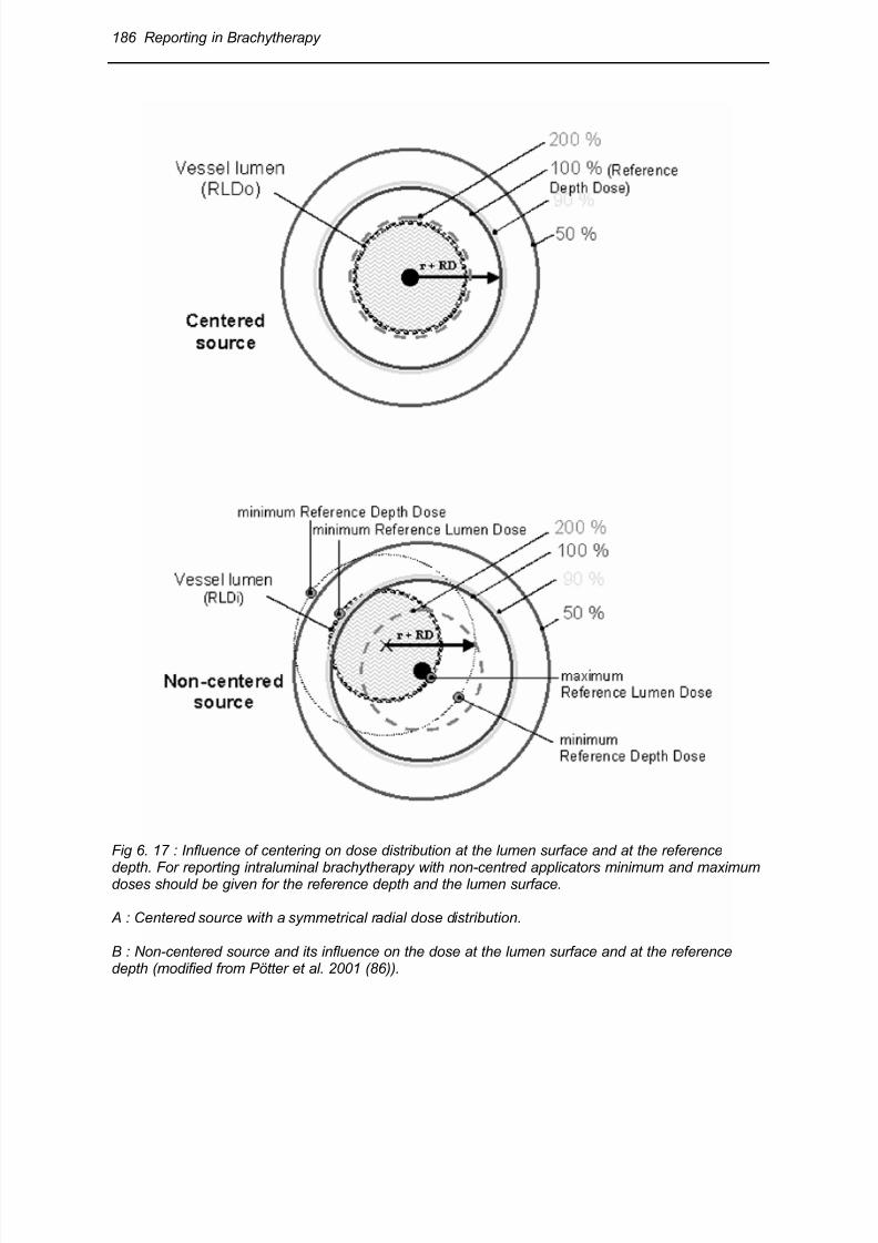
8/11/2019 Reporting in Brachytherapy
http://slidepdf.com/reader/full/reporting-in-brachytherapy 34/63
186 Reporting in Brachytherapy
Fig 6. 17 : Influence of centering on dose distribution at the lumen surface and at the reference
depth. For reporting intraluminal brachytherapy with non-centred applicators minimum and maximumdoses should be given for the reference depth and the lumen surface.
A : Centered source with a symmetrical radial dose distribution.
B : Non-centered source and its influence on the dose at the lumen surface and at the referencedepth (modified from Pötter et al. 2001 (86)).
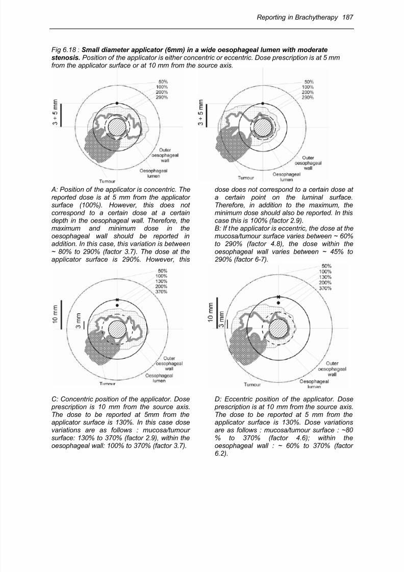
8/11/2019 Reporting in Brachytherapy
http://slidepdf.com/reader/full/reporting-in-brachytherapy 35/63
Reporting in Brachytherapy 187
Fig 6.18 : Small diameter applicator (6mm) in a wide oesophageal lumen with moderatestenosis. Position of the applicator is either concentric or eccentric. Dose prescription is at 5 mmfrom the applicator surface or at 10 mm from the source axis.
A: Position of the applicator is concentric. The
reported dose is at 5 mm from the applicatorsurface (100%). However, this does notcorrespond to a certain dose at a certaindepth in the oesophageal wall. Therefore, themaximum and minimum dose in theoesophageal wall should be reported inaddition. In this case, this variation is between~ 80% to 290% (factor 3.7). The dose at theapplicator surface is 290%. However, this
dose does not correspond to a certain dose at
a certain point on the luminal surface.Therefore, in addition to the maximum, theminimum dose should also be reported. In thiscase this is 100% (factor 2.9).B: If the applicator is eccentric, the dose at themucosa/tumour surface varies between ~ 60%to 290% (factor 4.8), the dose within theoesophageal wall varies between ~ 45% to290% (factor 6-7).
C: Concentric position of the applicator. Dose prescription is 10 mm from the source axis.The dose to be reported at 5mm from theapplicator surface is 130%. In this case dosevariations are as follows : mucosa/tumoursurface: 130% to 370% (factor 2.9), within theoesophageal wall: 100% to 370% (factor 3.7).
D: Eccentric position of the applicator. Dose prescription is at 10 mm from the source axis.The dose to be reported at 5 mm from theapplicator surface is 130%. Dose variationsare as follows : mucosa/tumour surface : ~80% to 370% (factor 4.6); within theoesophageal wall : ~ 60% to 370% (factor6.2).
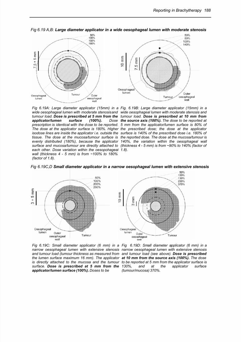
8/11/2019 Reporting in Brachytherapy
http://slidepdf.com/reader/full/reporting-in-brachytherapy 36/63
Reporting in Brachytherapy 188
Fig 6.19 A,B: Large diameter applicator in a wide oesophageal lumen with moderate stenosis
Fig 6.19A: Large diameter applicator (15mm) in awide oesophageal lumen with moderate stenosis andtumour load. Dose is prescribed at 5 mm from the
applicator/lumen surface (100%). Dose prescription is identical with the dose to be reported.The dose at the applicator surface is 180%. Higherisodose lines are inside the applicator i.e. outside thetissue. The dose at the mucosa/tumour surface isevenly distributed (180%), because the applicatorsurface and mucosa/tumour are directly attached toeach other. Dose variation within the oesopohagealwall (thickness 4 - 5 mm) is from ~100% to 180%(factor of 1.8).
Fig. 6.19B: Large diameter applicator (15mm) in awide oesophageal lumen with moderate stenosis andtumour load. Dose is prescribed at 10 mm from
the source axis (100%). The dose to be reported at5 mm from the applicator/lumen surface is 80% ofthe prescribed dose; the dose at the applicatorsurface is 140% of the prescribed dose i.e. 180% ofthe reported dose. The dose at the mucosa/tumour is140%, the variation within the oesophageal wall(thickness 4 - 5 mm) is from ~90% to 140% (factor of1.8).
Fig 6.19C,D Small diameter applicator in a narrow oesophageal lumen with extensive stenosis
Fig 6.19C: Small diameter applicator (6 mm) in anarrow oesophageal lumen with extensive stenosisand tumour load (tumour thickness as measured fromthe lumen surface maximum 16 mm). The applicatoris directly attached to the mucosa and the tumoursurface. Dose is prescribed at 5 mm from theapplicator/lumen surface (100%). Doses to be
Fig 6.19D: Small diameter applicator (6 mm) in anarrow oesophageal lumen with extensive stenosisand tumour load (see above). Dose is prescribedat 10 mm from the source axis (100%). The doseto be reported at 5 mm from the applicator surface is130%, and at the applicator surface(tumour/mucosa) 370%.
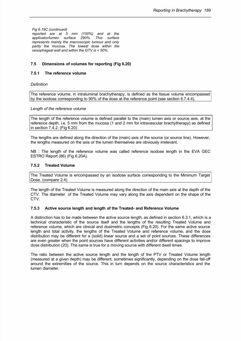
8/11/2019 Reporting in Brachytherapy
http://slidepdf.com/reader/full/reporting-in-brachytherapy 37/63
Reporting in Brachytherapy 189
Fig 6.19C (continued)reported are at 5 mm (100%) and at theapplicator/lumen surface 290%. This surfacerepresents mainly the macroscopic tumour and only partly the mucosa. The lowest dose within theoesophageal wall and within the GTV is < 50%.
7.5 Dimensions of volumes for reporting (Fig 6.20)
7.5.1 The reference volume
Definition
The reference volume, in intraluminal brachytherapy, is defined as the tissue volume encompassedby the isodose corresponding to 90% of the dose at the reference point (see section 6.7.4.4).
Length of the reference volume
The length of the reference volume is defined parallel to the (main) lumen axis or source axis, at thereference depth, i.e. 5 mm from the mucosa (1 and 2 mm for intravascular brachytherapy) as definedin section 7.4.2. (Fig 6.20)
The lengths are defined along the direction of the (main) axis of the source (or source line). However,the lengths measured on the axis or the lumen themselves are obviously irrelevant.
NB : The length of the reference volume was called reference isodose length in the EVA GECESTRO Report (86) (Fig 6.20A).
7.5.2 Treated Volume
The Treated Volume is encompassed by an isodose surface corresponding to the Minimum Target
Dose. (compare 2.4)
The length of the Treated Volume is measured along the direction of the main axis at the depth of theCTV. The diameter of the Treated Volume may vary along the axis dependent on the shape of theCTV.
7.5.3 Active source length and length of the Treated- and Reference Volume
A distinction has to be made between the active source length, as defined in section 6.3.1, which is atechnical characteristic of the source itself and the lengths of the resulting Treated Volume andreference volume, which are clinical and dosimetric concepts (Fig 6.20). For the same active sourcelength and total activity, the lengths of the Treated Volume and reference volume, and the dosedistribution may be different for a (solid) linear source and a set of point sources. These differencesare even greater when the point sources have different activities and/or different spacings to improvedose distribution (20). The same is true for a moving source with different dwell times.
The ratio between the active source length and the length of the PTV or Treated Volume length(measured at a given depth) may be different, sometimes significantly, depending on the dose fall-offaround the extremities of the source. This in turn depends on the source characteristics and thelumen diameter.
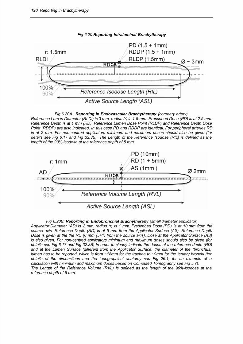
8/11/2019 Reporting in Brachytherapy
http://slidepdf.com/reader/full/reporting-in-brachytherapy 38/63
190 Reporting in Brachytherapy
Fig 6.20 Reporting Intraluminal Brachytherapy
Fig 6.20A : Reporting in Endovascular Brachytherapy (coronary artery).
Reference Lumen Diameter (RLDi) is 3 mm, radius (r) is 1.5 mm. Prescribed Dose (PD) is at 2.5 mm.Reference Depth is at 1 mm (RD). Reference Lumen Dose Point (RLDP) and Reference Depth DosePoint (RDDP) are also indicated. In this case PD and RDDP are identical. For peripheral arteries RDis at 2 mm. For non-centred applicators minimum and maximum doses should also be given (fordetails see Fig 6.17 and Fig 32.3B). The Length of the Reference Isodose (RIL) is defined as thelength of the 90%-isodose at the reference depth of 5 mm.
Fig 6.20B: Reporting in Endobronchial Brachytherapy (small diameter applicator) Applicator Diameter (AD) is 2 mm, radius (r) is 1 mm. Prescribed Dose (PD) is at 10 mm from thesource axis. Reference Depth (RD) is at 5 mm from the Applicator Surface (AS). Reference DepthDose is given at the the RD (6 mm (5+1) from the source axis). Dose at the Applicator Surface (AS)
is also given. For non-centred applicators minimum and maximum doses should also be given (fordetails see Fig 6.17 and Fig 32.3B) In order to clearly indicate the doses at the reference depth (RD)and at the Lumen Surface (different from the Applicator Surface) the diameter of the (bronchus)lumen has to be reported, which is from ~18mm for the trachea to ~9mm for the tertiary bronchi (fordetails of the dimensilons and the topogrophical anatomy see Fig 26.1; for an example of acalculation with minimum and maximum doses based on Computed Tomography see Fig 5.7).The Length of the Reference Volume (RVL) is defined as the length of the 90%-isodose at thereference depth of 5 mm.
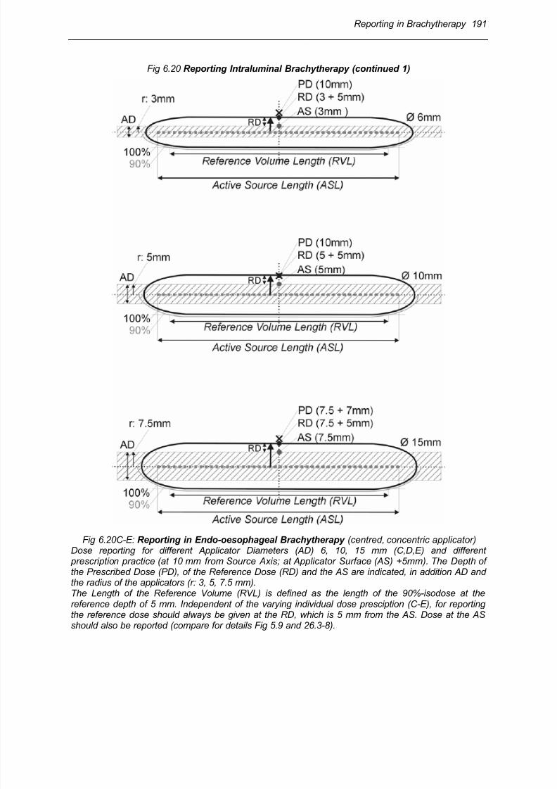
8/11/2019 Reporting in Brachytherapy
http://slidepdf.com/reader/full/reporting-in-brachytherapy 39/63
Reporting in Brachytherapy 191
Fig 6.20 Reporting Intraluminal Brachytherapy (continued 1)
Fig 6.20C-E: Reporting in Endo-oesophageal Brachytherapy (centred, concentric applicator)
Dose reporting for different Applicator Diameters (AD) 6, 10, 15 mm (C,D,E) and different prescription practice (at 10 mm from Source Axis; at Applicator Surface (AS) +5mm). The Depth ofthe Prescribed Dose (PD), of the Reference Dose (RD) and the AS are indicated, in addition AD andthe radius of the applicators (r: 3, 5, 7.5 mm).The Length of the Reference Volume (RVL) is defined as the length of the 90%-isodose at thereference depth of 5 mm. Independent of the varying individual dose presciption (C-E), for reportingthe reference dose should always be given at the RD, which is 5 mm from the AS. Dose at the ASshould also be reported (compare for details Fig 5.9 and 26.3-8).
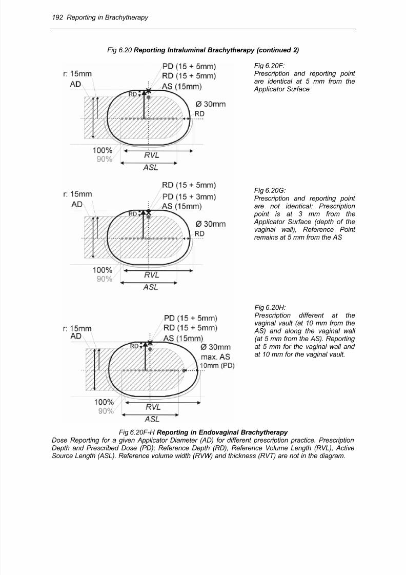
8/11/2019 Reporting in Brachytherapy
http://slidepdf.com/reader/full/reporting-in-brachytherapy 40/63
192 Reporting in Brachytherapy
Fig 6.20 Reporting Intraluminal Brachytherapy (continued 2)
Fig 6.20F:Prescription and reporting pointare identical at 5 mm from the Applicator Surface
Fig 6.20G:
Prescription and reporting pointare not identical: Prescription point is at 3 mm from the Applicator Surface (depth of thevaginal wall), Reference Pointremains at 5 mm from the AS
Fig 6.20H:Prescription different at thevaginal vault (at 10 mm from the AS) and along the vaginal wall(at 5 mm from the AS). Reportingat 5 mm for the vaginal wall andat 10 mm for the vaginal vault.
Fig 6.20F-H Reporting in Endovaginal Brachytherapy Dose Reporting for a given Applicator Diameter (AD) for different prescription practice. PrescriptionDepth and Prescribed Dose (PD); Reference Depth (RD), Reference Volume Length (RVL), ActiveSource Length (ASL). Reference volume width (RVW) and thickness (RVT) are not in the diagram.
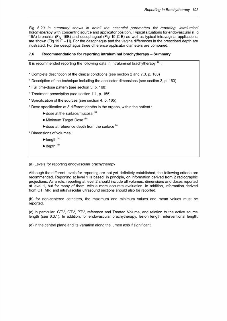
8/11/2019 Reporting in Brachytherapy
http://slidepdf.com/reader/full/reporting-in-brachytherapy 41/63
Reporting in Brachytherapy 193
Fig 6.20 in summary shows in detail the essential parameters for reporting intraluminalbrachytherapy with concentric source and applicator position. Typical situations for endovascular (Fig19A) bronchial (Fig 19B) and oesophagael (Fig 19 C-E) as well as typical intravaginal applicationsare shown (Fig 19 F – H). For the oesophagus and the vagina differences in the prescribed depth areillustrated. For the oesophagus three difference applicator diameters are compared.
7.6 Recommendations for reporting intraluminal brachytherapy – Summary
It is recommended reporting the following data in intraluminal brachytherapy(a)
:
* Complete description of the clinical conditions (see section 2 and 7.3, p. 183)
* Description of the technique including the applicator dimensions (see section 3, p. 163)
* Full time-dose pattern (see section 5, p. 168)
* Treatment prescription (see section 1.1, p. 155)
* Specification of the sources (see section 4, p. 165)
* Dose specification at 3 different depths in the organs, within the patient :
►dose at the surface/mucosa (b)
►Minimum Target Dose(b)
►dose at reference depth from the surface(b)
* Dimensions of volumes :
►length(c)
►depth(d)
(a) Levels for reporting endovascular brachytherapy
Although the different levels for reporting are not yet definitely established, the following criteria arerecommended. Reporting at level 1 is based, in principle, on information derived from 2 radiographicprojections. As a rule, reporting at level 2 should include all volumes, dimensions and doses reportedat level 1, but for many of them, with a more accurate evaluation. In addition, information derivedfrom CT, MRI and intravascular ultrasound sections should also be reported.
(b) for non-centered catheters, the maximum and minimum values and mean values must bereported.
(c) in particular, GTV, CTV, PTV, reference and Treated Volume, and relation to the active sourcelength (see 6.3.1). In addition, for endovascular brachytherapy, lesion length, interventional length.
(d) in the central plane and its variation along the lumen axis if significant.
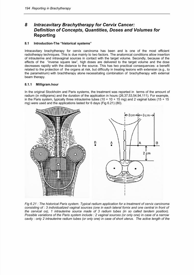
8/11/2019 Reporting in Brachytherapy
http://slidepdf.com/reader/full/reporting-in-brachytherapy 42/63
194 Reporting in Brachytherapy
8 Intracavitary Brachytherapy for Cervix Cancer:Definition of Concepts, Quantities, Doses and Volumes forReporting
8.1 Introduction-The “historical systems”
Intracavitary brachytherapy for cervix carcinoma has been and is one of the most efficientradiotherapy techniques. This is due mainly to two factors. The anatomical conditions allow insertionof intrauterine and intravaginal sources in contact with the target volume. Secondly, because of theeffects of the “inverse square law”, high doses are delivered to the target volume and the dosedecreases rapidly with the distance to the source. This has two practical consequences: a benefitrelated to the protection of the organs at risk, but difficulty in treating lesions with extension (e.g., tothe parametrium) with brachtherapy alone necessitating combination of brachytherapy with externalbeam therapy.
8.1.1 Milligram.hour
In the original Stockholm and Paris systems, the treatment was reported in terms of the amount of
radium (in milligrams) and the duration of the application in hours (26,37,53,54,94,111). For example,in the Paris system, typically three intrauterine tubes (10 + 10 + 15 mg) and 2 vaginal tubes (15 + 15mg) were used and the applications lasted for 6 days (Fig 6.21) (80).
Fig 6.21 : The historical Paris system. Typical radium application for a treatment of cervix carcinomaconsisting of : 3 individualized vaginal sources (one in each lateral fornix and one central in front ofthe cervical os), 1 intrauterine source made of 3 radium tubes (in so called tandem position).Possible variations of the Paris system include : 2 vaginal sources (or only one) in case of a narrowcavity : only 2 intrauterine radium tubes (or only one) in case of short uterus. The active length of the
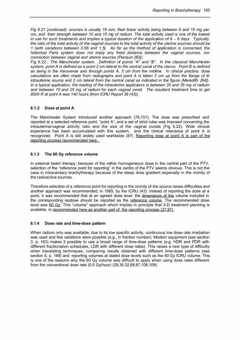
8/11/2019 Reporting in Brachytherapy
http://slidepdf.com/reader/full/reporting-in-brachytherapy 43/63
Reporting in Brachytherapy 195
Fig 6.21 (continued): sources is usually 16 mm, their linear activity being between 6 and 10 mg percm, and their strength between 10 and 15 mg of radium. The total activity used is one of the lowestin use for such treatments and implies a typical duration of the application of 6 – 8 days. Typically,the ratio of the total activity of the vaginal sources to the total activity of the uterine sources should be1 (with variations between 0.66 and 1.5). As far as the method of application is concerned, thehistorical Paris system does not imply any fixed distance between the vaginal sources, norconnection between vaginal and uterine sources (Pierquin [80]).Fig 6.22 : The Manchester system. Definition of points “A” and “B”. In the classical Manchestersystem, point A is defined as a point 2 cm lateral to the central canal of the uterus. Point B is definedas being in the transverse axis through points A, 5 cm from the midline. In clinical practice, dosecalculations are often made from radiographs and point A is taken 2 cm up from the flange of thintrauterine source and 2 cm lateral from the central canal as indicated in the figure (Meredith, [64]).In a typical application, the loading of the intrauterine applicators is between 20 and 35 mg of radiumand between 15 and 25 mg of radium for each vaginal ovoid. The resultant treatment time to get8000 R at point A was 140 hours (from ICRU Report 38 (43)).
8.1.2 Dose at point A
The Manchester System introduced another approach (76,101). The dose was prescribed andreported at a selected reference point, “point A”, and a set of strict rules was imposed concerning theintrauterine/vaginal activity ratio and the size of the vaginal ovoids (Fig 6.22). Wide clinicalexperience has been accumulated with this system, and the clinical relevance of point A isrecognized. Point A is still widely used worldwide (87). Reporting dose at point A is part of thereporting process recommended here .
8.1.3 The 60 Gy reference volume
In external beam therapy, because of the rather homogeneous dose in the central part of the PTV,selection of the “reference point for reporting” in the centre of the PTV seems obvious. This is not thecase in intracavitary brachytherapy because of the steep dose gradient especially in the vicinity of
the radioactive sources .
Therefore selection of a reference point for reporting in the vicinity of the source raises difficulties andanother approach was recommended, in 1985, by the ICRU (43): instead of reporting the dose at apoint, it was recommended that at an agreed dose level, the dimensions of the volume included inthe corresponding isodose should be reported as the reference volume. The recommended doselevel was 60 Gy. This “volume” approach which implies in principle that 3-D treatment planning isavailable, is recommended here as another part of the reporting process (27,87).
8.1.4 Dose rate and time-dose pattern
When radium only was available, due to its low specific activity, continuous low dose rate irradiation
was used and few variations were possible (e.g., in fraction number). Modern equipment (see section3, p. 163) makes it possible to use a broad range of time-dose patterns (e.g. HDR and PDR withdifferent fractionation schedules, LDR with different dose rates). This raises a new type of difficultywhen translating techniques, comparing results obtained with different time-dose patterns (seesection 5, p. 168) and reporting volumes at stated dose levels such as the 60 Gy ICRU volume. Thisis one of the reasons why the 60 Gy volume was difficult to apply when using dose rates differentfrom the conventional dose rate (0.5 Gy/hour) (29,30,32,68,87,108,109).
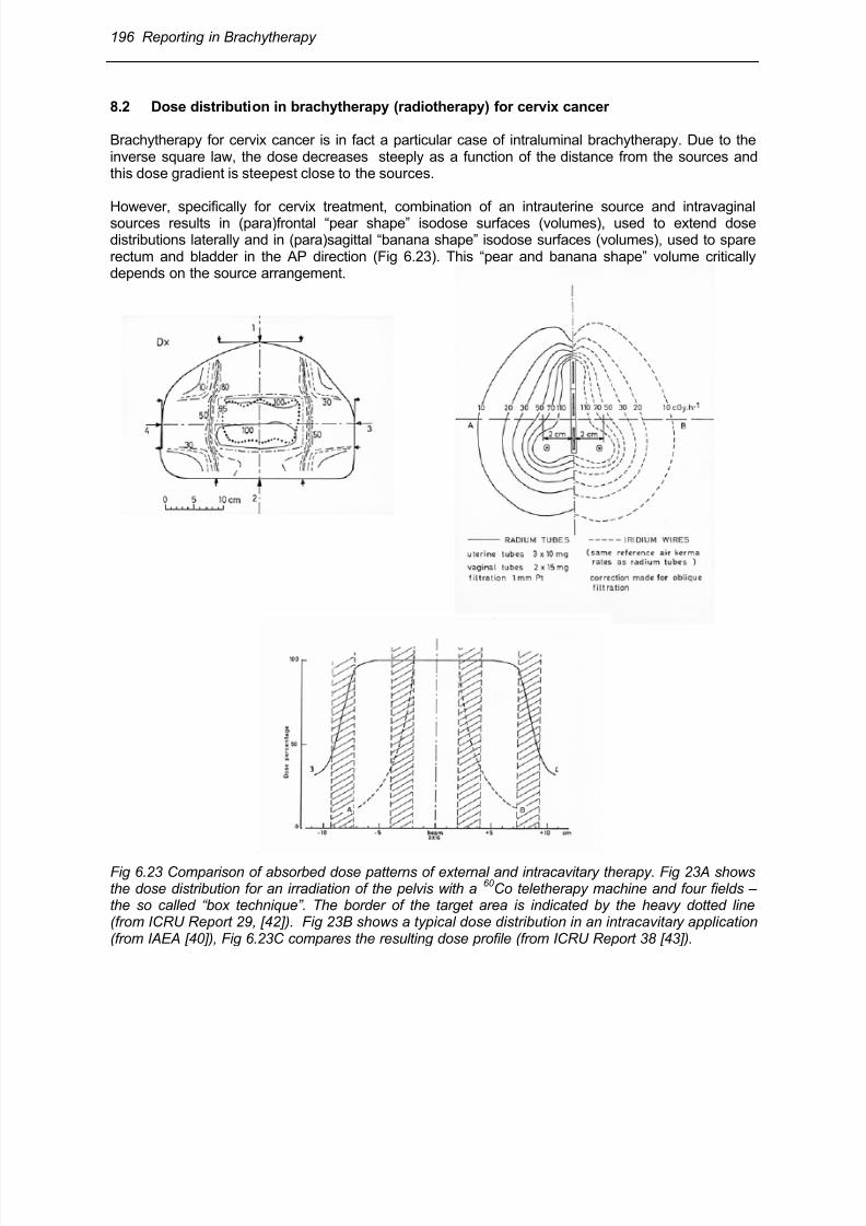
8/11/2019 Reporting in Brachytherapy
http://slidepdf.com/reader/full/reporting-in-brachytherapy 44/63
196 Reporting in Brachytherapy
8.2 Dose distribution in brachytherapy (radiotherapy) for cervix cancer
Brachytherapy for cervix cancer is in fact a particular case of intraluminal brachytherapy. Due to theinverse square law, the dose decreases steeply as a function of the distance from the sources andthis dose gradient is steepest close to the sources.
However, specifically for cervix treatment, combination of an intrauterine source and intravaginalsources results in (para)frontal “pear shape” isodose surfaces (volumes), used to extend dosedistributions laterally and in (para)sagittal “banana shape” isodose surfaces (volumes), used to sparerectum and bladder in the AP direction (Fig 6.23). This “pear and banana shape” volume criticallydepends on the source arrangement.
Fig 6.23 Comparison of absorbed dose patterns of external and intracavitary therapy. Fig 23A showsthe dose distribution for an irradiation of the pelvis with a
60 Co teletherapy machine and four fields –
the so called “box technique”. The border of the target area is indicated by the heavy dotted line(from ICRU Report 29, [42]). Fig 23B shows a typical dose distribution in an intracavitary application(from IAEA [40]), Fig 6.23C compares the resulting dose profile (from ICRU Report 38 [43]).
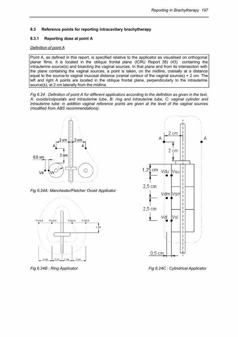
8/11/2019 Reporting in Brachytherapy
http://slidepdf.com/reader/full/reporting-in-brachytherapy 45/63
Reporting in Brachytherapy 197
8.3 Reference points for reporting intracavitary brachytherapy
8.3.1 Reporting dose at point A
Definition of point A
Point A, as defined in this report, is specified relative to the applicator as visualised on orthogonalplanar films. It is located in the oblique frontal plane (ICRU Report 38) (43) containing theintrauterine source(s) and bisecting the vaginal sources. In that plane and from its intersection withthe plane containing the vaginal sources, a point is taken, on the midline, cranially at a distanceequal to the source-to vaginal mucosal distance (cranial contour of the vaginal sources) + 2 cm. Theleft and right A points are located in the oblique frontal plane, perpendicularly to the intrauterinesource(s), at 2 cm laterally from the midline.
Fig 6.24 : Definition of point A for different applicators according to the definition as given in the text, A: ovoids/colpostats and intrauterine tube, B: ring and intrauterine tube, C: vaginal cylinder andintrauterine tube: in addition vaginal reference points are given at the level of the vaginal sources(modified from ABS recommendations).
Fig 6.24A: Manchester/Fletcher Ovoid Applicator
Fig 6.24B : Ring Applicator Fig 6.24C : Cylindrical Applicator
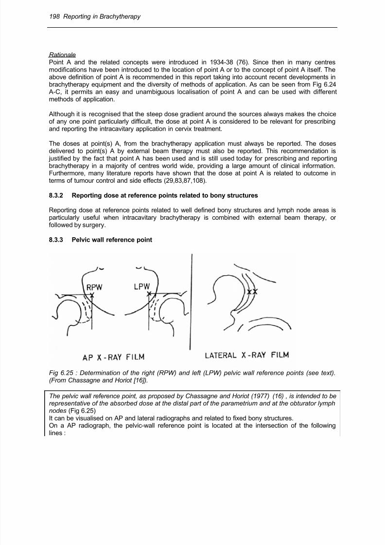
8/11/2019 Reporting in Brachytherapy
http://slidepdf.com/reader/full/reporting-in-brachytherapy 46/63
198 Reporting in Brachytherapy
RationalePoint A and the related concepts were introduced in 1934-38 (76). Since then in many centresmodifications have been introduced to the location of point A or to the concept of point A itself. Theabove definition of point A is recommended in this report taking into account recent developments inbrachytherapy equipment and the diversity of methods of application. As can be seen from Fig 6.24 A-C, it permits an easy and unambiguous localisation of point A and can be used with differentmethods of application.
Although it is recognised that the steep dose gradient around the sources always makes the choiceof any one point particularly difficult, the dose at point A is considered to be relevant for prescribingand reporting the intracavitary application in cervix treatment.
The doses at point(s) A, from the brachytherapy application must always be reported. The dosesdelivered to point(s) A by external beam therapy must also be reported. This recommendation is justified by the fact that point A has been used and is still used today for prescribing and reportingbrachytherapy in a majority of centres world wide, providing a large amount of clinical information.Furthermore, many literature reports have shown that the dose at point A is related to outcome interms of tumour control and side effects (29,83,87,108).
8.3.2 Reporting dose at reference points related to bony structures
Reporting dose at reference points related to well defined bony structures and lymph node areas isparticularly useful when intracavitary brachytherapy is combined with external beam therapy, orfollowed by surgery.
8.3.3 Pelvic wall reference point
Fig 6.25 : Determination of the right (RPW) and left (LPW) pelvic wall reference points (see text).
(From Chassagne and Horiot [16]).
The pelvic wall reference point, as proposed by Chassagne and Horiot (1977) (16) , is intended to berepresentative of the absorbed dose at the distal part of the parametrium and at the obturator lymphnodes (Fig 6.25)It can be visualised on AP and lateral radiographs and related to fixed bony structures.On a AP radiograph, the pelvic-wall reference point is located at the intersection of the followinglines :
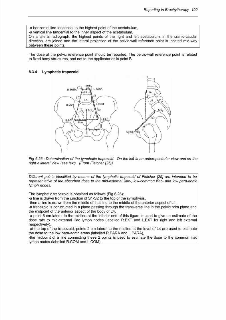
8/11/2019 Reporting in Brachytherapy
http://slidepdf.com/reader/full/reporting-in-brachytherapy 47/63
Reporting in Brachytherapy 199
-a horizontal line tangential to the highest point of the acetabulum,-a vertical line tangential to the inner aspect of the acetabulum.On a lateral radiograph, the highest points of the right and left acetabulum, in the cranio-caudaldirection, are joined and the lateral projection of the pelvic-wall reference point is located mid-waybetween these points.
The dose at the pelvic reference point should be reported. The pelvic-wall reference point is relatedto fixed bony structures, and not to the applicator as is point B.
8.3.4 Lymphatic trapezoid
Fig 6.26 : Determination of the lymphatic trapezoid. On the left is an anteroposterior view and on theright a lateral view (see text). (From Fletcher (25))
Different points identified by means of the lymphatic trapezoid of Fletcher [25] are intended to berepresentative of the absorbed dose to the mid-external iliac-, low-common iliac- and low para-aorticlymph nodes.
The lymphatic trapezoid is obtained as follows (Fig 6.26):-a line is drawn from the junction of S1-S2 to the top of the symphysis,-then a line is drawn from the middle of that line to the middle of the anterior aspect of L4,-a trapezoid is constructed in a plane passing through the transverse line in the pelvic brim plane andthe midpoint of the anterior aspect of the body of L4,-a point 6 cm lateral to the midline at the inferior end of this figure is used to give an estimate of thedose rate to mid-external iliac lymph nodes (labelled R.EXT and L.EXT for right and left external
respectively),-at the top of the trapezoid, points 2 cm lateral to the midline at the level of L4 are used to estimatethe dose to the low para-aortic areas (labelled R.PARA and L.PARA),-the midpoint of a line connecting these 2 points is used to estimate the dose to the common iliaclymph nodes (labelled R.COM and L.COM).
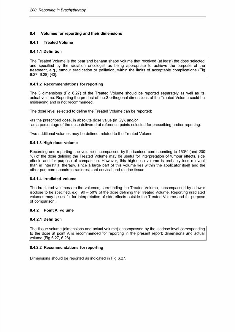
8/11/2019 Reporting in Brachytherapy
http://slidepdf.com/reader/full/reporting-in-brachytherapy 48/63
200 Reporting in Brachytherapy
8.4 Volumes for reporting and their dimensions
8.4.1 Treated Volume
8.4.1.1 Definition
The Treated Volume is the pear and banana shape volume that received (at least) the dose selectedand specified by the radiation oncologist as being appropriate to achieve the purpose of thetreatment, e.g., tumour eradication or palliation, within the limits of acceptable complications (Fig6.27, 6.28) [43].
8.4.1.2 Recommendations for reporting
The 3 dimensions (Fig 6.27) of the Treated Volume should be reported separately as well as itsactual volume. Reporting the product of the 3 orthogonal dimensions of the Treated Volume could bemisleading and is not recommended.
The dose level selected to define the Treated Volume can be reported:
-as the prescribed dose, in absolute dose value (in Gy), and/or-as a percentage of the dose delivered at reference points selected for prescribing and/or reporting.
Two additional volumes may be defined, related to the Treated Volume
8.4.1.3 High-dose volume
Recording and reporting the volume encompassed by the isodose corresponding to 150% (and 200%) of the dose defining the Treated Volume may be useful for interpretation of tumour effects, sideeffects and for purpose of comparison. However, this high-dose volume is probably less relevantthan in interstitial therapy, since a large part of this volume lies within the applicator itself and theother part corresponds to radioresistant cervical and uterine tissue.
8.4.1.4 Irradiated volume
The irradiated volumes are the volumes, surrounding the Treated Volume, encompassed by a lowerisodose to be specified, e.g., 90 – 50% of the dose defining the Treated Volume. Reporting irradiatedvolumes may be useful for interpretation of side effects outside the Treated Volume and for purposeof comparison.
8.4.2 Point A volume
8.4.2.1 Definition
The tissue volume (dimensions and actual volume) encompassed by the isodose level corresponding
to the dose at point A is recommended for reporting in the present report: dimensions and actualvolume (Fig 6.27, 6.28)
8.4.2.2 Recommendations for reporting
Dimensions should be reported as indicated in Fig 6.27.

8/11/2019 Reporting in Brachytherapy
http://slidepdf.com/reader/full/reporting-in-brachytherapy 49/63
Reporting in Brachytherapy 201
The dose level at point A may - or may not - be equal to the dose level defining the Treated Volume,depending whether the radiation oncologist specifies that the dose at point A defines the TreatedVolume (i.e., the dose necessary to achieve the goal of the treatment).
The dimensions of the point A volume describe the geometrical features of the pear and bananashape isodoses (long vs short, wide vs small, thick vs thin) depending on the source arrangement,for the same dose to point A and the same TRAK.
8.4.3 Reference volume
8.4.3.1 Definition
The reference volume is the volume encompassed by the reference isodose, selected and specifiedto compare treatments performed in different centres using different techniques.The dose selected to define the reference volume shall imply a consensus at an international level(or at least between the involved centres).
8.4.3.2 Rationale for the concept of reference volume
When comparing brachytherapy applications performed in different centres using differenttechniques, different volumes have to be compared: the Treated Volumes and the point A volumes(they have also to be correlated with the respective PTVs).
However, for a given application, Treated Volumes (or point A volumes) of different dimensions maybe reported depending on the dose level selected to define these volumes. Inversely, applicationsreported as delivering the same (nominal) dose may actually be quite different if this dosecorresponds to different volumes (24).
Therefore, for appropriate comparisons, a dose level must be chosen and agreed as “referencedose”. The volume encompassed by that dose is the “Reference Volume”. The selected reference
dose may or may not be equal to the dose at point A, which may, in turn, be equal or not to the dosedefining the Treated Volume.
8.4.3.3 Selection of the reference dose level
Firstly, as a sine qua non condition, selection of the reference dose level implies a consensusbetween centres: the goal for introducing the concept of the reference volume is indeed to allowcentres to perform relevant comparisons.
Secondly, to be clinically relevant, the reference volume should be rather close to the TreatedVolume and/or the „point A volume“ .
In ICRU Report 38 (43), a reference dose level of 60 Gy is recommended. This dose is indeedappropriate for very early disease (e.g. stage IA) when brachytherapy alone is applied, or in stage Iand proximal IIB, when brachytherapy is combined with radical surgery. In such situations, the dosedefining the Treated Volume is close to 60 Gy (28).

8/11/2019 Reporting in Brachytherapy
http://slidepdf.com/reader/full/reporting-in-brachytherapy 50/63
202 Reporting in Brachytherapy
Fig 6.27: Geometry for measurement of the dimensions of the pear-shape volume (Treated Volume,“point A” volume, reference volume) in a typical treatment of cervix carcinoma.-Plane a is the “oblique frontal plane” that contains the intrauterine device. It is obtained by rotation ofthe frontal plane around a transverse axis.-Plane b is the “oblique sagittal plane” that contains the intrauterine device. It is obtained by rotationof the sagittal plane around the AP axis. The height (dh) and the width (dw) of the pear-shape
volume are measured in plane a as the maximal sizes parallel and perpendicular to the uterineapplicator, respectively. The thickness (dt) of the pear-shape volume is measured in plane b as themaximal size perpendicular to the uterine applicator.The dimensions dh, dw and dt refer to the brachytherapy application only (left part of the figure).When combination of brachytherapy and external beam therapy is taken into account (right part ofthe figure), these dimensions are symbolized by dH, dW and dT, respectively.(modified from ICRU Report 38 (43)
In definitive treatment the total dose at point A and/or in the PTV2 (tumour extension at the time ofbrachytherapy) currently ranges between 75 and 90 Gy (and above). This includes limited disease(e.g. stage IB1, stage IIB proximal) and the wide range of extensive disease (stage IB2 to IIIB/IVA).Therefore, one should consider selecting as reference volume, the volume encompassed by a higher
dose level e.g. the 75 or 85 Gy isodose.
Selection of 60 Gy (definitive treatment for very early disease; combination treatment with surgeryfor limited disease) and 75/85 Gy (definitive treatment for limited and extensive disease) to definethe reference volume does not imply that these doses are recommended as optimal therapeuticdoses. It is only for purpose of comparison that the concept of reference volume was introduced inICRU Report 38 and is recommended here again. (Fig 6.28).
8/11/2019 Reporting in Brachytherapy
http://slidepdf.com/reader/full/reporting-in-brachytherapy 51/63
Reporting in Brachytherapy 203
Fig 6.28: Definitive cervix cancerbrachytherapy (IB, IIB proximal, for
details see 14.7-9). Reporting doses andvolumes for five different clinicalsituations (tumour sizes) and treat-mentschedules. For cases (a), (b) and (c)brachytherapy is combined with externalbeam therapy. For cases (d) and (e),brachytherapy alone is applied (d) preop.BT (“IGR”); (e) BT alone (“Manchester”).The same brachy-therapy technique isassumed for all cases.For cases (a , (b) and (c), the TreatedVolume is defined by the 85 Gy isodose.For cases (d) and (e) the TreatedVolume is defined by the 60 and 75 Gy
isodoses, respectively.For the five clinical cases, the GTVs areshown together with the 60-75-85-95 Gyisodose curves. On the lower part of thefigure, the different isodoses are presented at a larger scale to illustratethe differences in the volumedimensions.
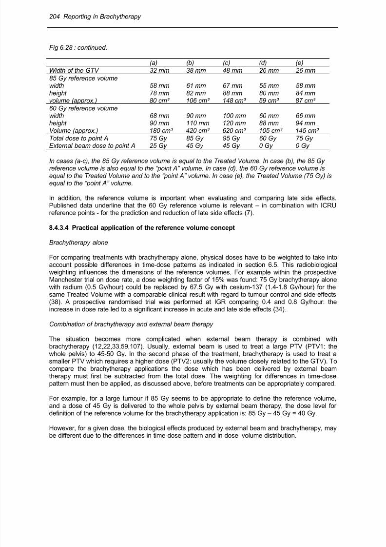
8/11/2019 Reporting in Brachytherapy
http://slidepdf.com/reader/full/reporting-in-brachytherapy 52/63
204 Reporting in Brachytherapy
Fig 6.28 : continued.
(a) (b) (c) (d) (e)
Width of the GTV 32 mm 38 mm 48 mm 26 mm 26 mm
85 Gy reference volumewidth 58 mm 61 mm 67 mm 55 mm 58 mm
height 78 mm 82 mm 88 mm 80 mm 84 mmvolume (approx.) 80 cm³ 106 cm³ 148 cm³ 59 cm³ 87 cm³
60 Gy reference volumewidth 68 mm 90 mm 100 mm 60 mm 66 mmheight 90 mm 110 mm 120 mm 88 mm 94 mmVolume (approx.) 180 cm³ 420 cm³ 620 cm³ 105 cm³ 145 cm³
Total dose to point A 75 Gy 85 Gy 95 Gy 60 Gy 75 GyExternal beam dose to point A 25 Gy 45 Gy 45 Gy 0 Gy 0 Gy
In cases (a-c), the 85 Gy reference volume is equal to the Treated Volume. In case (b), the 85 Gyreference volume is also equal to the “point A” volume. In case (d), the 60 Gy reference volume isequal to the Treated Volume and to the “point A” volume. In case (e), the Treated Volume (75 Gy) isequal to the “point A” volume.
In addition, the reference volume is important when evaluating and comparing late side effects.Published data underline that the 60 Gy reference volume is relevant – in combination with ICRUreference points - for the prediction and reduction of late side effects (7).
8.4.3.4 Practical application of the reference volume concept
Brachytherapy alone
For comparing treatments with brachytherapy alone, physical doses have to be weighted to take intoaccount possible differences in time-dose patterns as indicated in section 6.5. This radiobiologicalweighting influences the dimensions of the reference volumes. For example within the prospectiveManchester trial on dose rate, a dose weighting factor of 15% was found: 75 Gy brachytherapy alone
with radium (0.5 Gy/hour) could be replaced by 67.5 Gy with cesium-137 (1.4-1.8 Gy/hour) for thesame Treated Volume with a comparable clinical result with regard to tumour control and side effects(38). A prospective randomised trial was performed at IGR comparing 0.4 and 0.8 Gy/hour: theincrease in dose rate led to a significant increase in acute and late side effects (34).
Combination of brachytherapy and external beam therapy
The situation becomes more complicated when external beam therapy is combined withbrachytherapy (12,22,33,59,107). Usually, external beam is used to treat a large PTV (PTV1: thewhole pelvis) to 45-50 Gy. In the second phase of the treatment, brachytherapy is used to treat asmaller PTV which requires a higher dose (PTV2: usually the volume closely related to the GTV). Tocompare the brachytherapy applications the dose which has been delivered by external beamtherapy must first be subtracted from the total dose. The weighting for differences in time-dose
pattern must then be applied, as discussed above, before treatments can be appropriately compared.
For example, for a large tumour if 85 Gy seems to be appropriate to define the reference volume,and a dose of 45 Gy is delivered to the whole pelvis by external beam therapy, the dose level fordefinition of the reference volume for the brachytherapy application is: 85 Gy – 45 Gy = 40 Gy.
However, for a given dose, the biological effects produced by external beam and brachytherapy, maybe different due to the differences in time-dose pattern and in dose–volume distribution.
8/11/2019 Reporting in Brachytherapy
http://slidepdf.com/reader/full/reporting-in-brachytherapy 53/63
Reporting in Brachytherapy 205
The dose rate of the brachytherapy application may be different from the conventional low dose rate(0.5 Gy/hour): e.g. 1.5 Gy/hour (LDR), 20-30 Gy/hour (HDR). The dose level selected to define thereference volume is the dose which is considered to be “equivalent” to or “isoeffective” with the dosedelivered at the conventional low dose rate, in the same clinical condition (Fig 6.28).
A biological weighting factor, Wrate
, thus has to be applied to compensate/normalize for differences indose rate. The difficult radiobiological problem raised by the selection of this weighting factor isdiscussed in Chapter 4. The value of Wrate actually applied should always be based on widelyaccepted models and clearly reported. It should be kept in mind that the biological weighting factorWrate is valid only for a given tissue, effect and dose/dose rate.
Following the same example as above, if 85 Gy is considered appropriate to define the referencevolume for conventional low dose rate, and if 45 Gy external beam therapy has been delivered, adose of 85 Gy – 45 Gy = 40 Gy defines the reference volume at LDR brachytherapy. For HDRbrachytherapy, 4 fractions of 7 Gy are considered to correspond to 40 Gy LDR brachytherapyaccording to biological models and clinical experience (79,88). The reference volume is thus definedas the volume encompassed by the 4 x 7 Gy isodose (assuming, α/β = 10 for the effects on thetumour, see chapter 4). The three orthogonal dimensions and the volume of that reference volume (7
Gy x 4) must be reported as recommended above, and can be compared with the dimensions ofother brachytherapy applications performed with HDR, MDR, or LDR (88). An analogue proceduremust be followed when using the 60 Gy reference volume.
NB : Additional recommendations for reporting the 3 dimensions of the volumes
(1) As an additional recommendation, the width (dwA) and the thickness (twA) of the volumesmeasured in the planes passing through Point A may also be reported. Indeed thesedimensions are closely related to the GTV/PTV2.
(2) The right and left dimensions of the width and the anterior and posterior dimensions of thethickness of the volumes should be reported separately if they differ significantly with regard tothe intrauterine source (e.g., if different loadings of vaginal sources are used).
(3) The 3 orthogonal dimensions of the volumes should be reported individually and not theirproduct. Firstly, for cervix carcinoma, because of the „pear shape“, the actual computedvolumes are much smaller (about 50%) compared with the product of their 3 dimensions.Secondly, the lateral and AP-PA dimensions are clinically meaningful for tumour control withregard to parametrial extension and complications, respectively.
8.4.4 Volume approach based on 3-D imaging and computer assisted 3-D dosecalculation
Development of 3-D image based treatment planning in brachytherapy has significantly improved the3 D assessment of dose-volume relations. Dose distribution can now be evaluated in different
volumes such as the GTV, CTV and PTV (24,27,29,89,95,97,104,105). Dose-volume histograms canbe derived and analysed but the methods for deriving the relevant information still need to be definedand no agreement has been reached so far (compare Fig 5.15,14.14,16.7,17.10).
In order to link the information gained so far from extensive clinical experience before these newtools were available, correlations of coverage of GTV and PTV with doses at point A and withreference volumes, such as 60, 75, and 85 Gy volumes should be analysed (24).
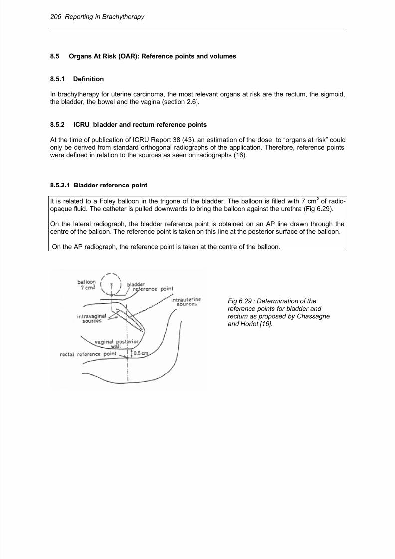
8/11/2019 Reporting in Brachytherapy
http://slidepdf.com/reader/full/reporting-in-brachytherapy 54/63
206 Reporting in Brachytherapy
8.5 Organs At Risk (OAR): Reference points and volumes
8.5.1 Definition
In brachytherapy for uterine carcinoma, the most relevant organs at risk are the rectum, the sigmoid,the bladder, the bowel and the vagina (section 2.6).
8.5.2 ICRU bladder and rectum reference points
At the time of publication of ICRU Report 38 (43), an estimation of the dose to “organs at risk” couldonly be derived from standard orthogonal radiographs of the application. Therefore, reference pointswere defined in relation to the sources as seen on radiographs (16).
8.5.2.1 Bladder reference point
It is related to a Foley balloon in the trigone of the bladder. The balloon is filled with 7 cm3
of radio-opaque fluid. The catheter is pulled downwards to bring the balloon against the urethra (Fig 6.29).
On the lateral radiograph, the bladder reference point is obtained on an AP line drawn through thecentre of the balloon. The reference point is taken on this line at the posterior surface of the balloon.
On the AP radiograph, the reference point is taken at the centre of the balloon.
Fig 6.29 : Determination of thereference points for bladder andrectum as proposed by Chassagneand Horiot [16].
8/11/2019 Reporting in Brachytherapy
http://slidepdf.com/reader/full/reporting-in-brachytherapy 55/63
Reporting in Brachytherapy 207
8.5.2.2 Rectum reference point
The reference point for the rectal dose is related to the applicator and located 5 mm behind theposterior vagina wall on an AP line drawn from the middle of the vaginal sources (Fig 6.29).
On the lateral radiograph, an anterior-posterior line is drawn from the lower end of the intrauterine
source (or from the middle of the intravaginal sources). The point is located on this line, 5 mm behindthe posterior vaginal wall (not in the contrast filling tube). The posterior vaginal wall is visualised,depending upon the technique, by means of an intravaginal mould or by opacification of the vaginalcavity with radio-opaque gauze used for packing.
On the frontal radiograph, this reference point is taken at the intersection of (the lower end of) theintrauterine source through the plane of the vaginal sources.
8.5.3 Clinical significance of the bladder and rectum reference points
The clinical significance of the bladder and rectum reference points has been questioned and is still amatter for debate (7,28,39,51,57,67,97,99,100).
A significant number of observations support a correlation between rectal complications and the doseto the rectum reference point (19,77,93,104). In contrast, the bladder reference point was found to bereproducible, but does not correlate well with bladder complications.
All investigators found that the actual maximum dose to the bladder was, in most cases, significantlyhigher than the dose at the ICRU reference points, usually located more cranially. Indeed, somecentres calculate the dose 1.5 - 2 cm cranial (Point ALG) relative to the ICRU Reference Point (8,27).
However, because of variation in individual anatomical conditions, extent of disease, applicatordesign and technique, it has not been possible so far to agree on new reference points to replace thepoints recommended in ICRU Report 38 (43) .
Different vaginal reference points are used in different traditions, e.g. at 5 mm lateral from the surface
of the ovoids at the level of the vaginal sources (see Fig 6.24C) or at the vaginal surface (25). Nointernational agreement has been reached on a definitive vaginal reference point.
8.5.4 Volume approach to evaluate doses in Organs At Risk
The development of 3-D image based treatment planning has significantly changed the situation.Dose distribution can now be evaluated in different volumes such as the GTV, CTV, PTV, TreatedVolume and Organs at Risk, such as bladder, rectum, sigmoid, bowel (24,27,29,89,95,97,104).Dose-volume histograms can be derived and analysed but there are not yet any generally agreedmethods (see Chapter 14).
In the present situation, following values are recommended for reporting doses to the Organs at Risk: 1°) The maximum bladder and rectum doses. The maximum dose to consider is the dose received
in a volume of at least 2 and 5 cm3
;
2°) The volume of the Organ At Risk that receives a dose close to or higher than the dose consideredto be significant in relation to tolerance. Because of lack of definitive data, volumes corresponding todose levels of 60- 90 Gy should be considered. The volumes should be reported in cm
3 (absolute
values) and as a percentage of the organ volume.

8/11/2019 Reporting in Brachytherapy
http://slidepdf.com/reader/full/reporting-in-brachytherapy 56/63
8/11/2019 Reporting in Brachytherapy
http://slidepdf.com/reader/full/reporting-in-brachytherapy 57/63
Reporting in Brachytherapy 209
When reporting at level 2/3, a series of CT and/or MRI sections are available as well as a 3-D dosedistribution and DVHs can be derived. The dose distribution for the GTV and the PTV can then bederived. Dose volume analysis should be done for doses used in traditional reporting, e.g. 60, 75, 85Gy. The dose distribution based on a point A prescription can also be analysed with regard tocoverage of GTV and PTV.
(e) The doses to the bladder and rectum ICRU reference points should be reported when reporting atlevel 1 (section 8.5.2-3). They can be evaluated from orthogonal radiographs, as defined in ICRU 38(43). However, this evaluation takes time and is not always possible due to the local conditions.
When reporting at level 2, a series of CT and/or MRI sections are available as well as a 3-D dosedistribution. DVHs can then be derived. The maximum bladder and rectal dose in a certain volume (2and 5 cm
3) should be reported as indicated in section 8.5.4. In addition, at level 2, the volume of the
organ at risk receiving a dose close to or higher than the dose considered to be significant in relationto tolerance should also be reported (e.g. 60/70/80 Gy).
(f) If in vivo measurements were performed, the method and the results should be reported.
8/11/2019 Reporting in Brachytherapy
http://slidepdf.com/reader/full/reporting-in-brachytherapy 58/63
210 Reporting in Brachytherapy
9 References
1. AAPM - American Association of Physicists in Medicine. Remote Afterloading Technology. AAPM Report No.41 1993; American Institute of Physics New York.
2. AAPM - American Association of Physicists in Medicine. Specification of brachytherapy sourcestrength. AAPM Report No.21 1987; American Institute of Physics New York.
3. AJCC - American Joint Committee on Cancer. (ed. Beahrs OJ, Henson D, Hutter RVP, et al.)Manual for Staging of Cancer 3
rd edn. 1988; Philadelphia J.P.Lippincott.
4. Amersham International plc, Amersham Laboratories, White Lion Road, Amersham,Buckinghamshire HP7 9LL, U.K.
5. Anderson LL, Hilaris BS, Wagner LK. A normograph for planar implant-planning.Endocuriether Hypertherm Onco 1995; 1: 9-15.
6. Anderson LL. A “natural” volume-dose histogram for brachytherapy. Med Phys 1986; 13: 898-903.
7. Barillot I, Horiot J, Maingon P, et al. Impact on Treatment Outcome and Late Effects ofCustomized Treatment Planning in Cervix Carcinomas: Baseline Results to Compare NewStrategies. Int J Radiation Oncology Biol Phys 2000; 48: 189-200.
8. Barillot I, Horiot JC, Maingon P, et al. Maximum and mean bladder dose defined byultrasonography. Comparison with the ICRU reference in gynecological brachytherapy.Radioth Oncol 1994; 30 (3): 231-38.
9. BCRU - British Committee on Radiation Units and Measurements. Specification ofbrachytherapy sources, memorandum from the British Committee on Radiation Units andMeasurements. Br J Radiol 1984; 57: 941-42.
10. Bernard M, Guille B, Duvalet G. Mesure du débit d’exposition linéique nominal des sources àune dimension, utilisées en curiethérapie. J Radiol Electrol 1975; 56: 785-90.
11. BIR - British Institute of Radiology. Recommendations for brachytherapy dosimetry. Report ofa joint working party of the BIR and the IPSM 1993. British Institute of Radiology.
12. Björkholm E. The development of brachytherapy and complementary external irradiation in thetreatment of cervical carcinoma, Workshop "Integration of external beam therapy andbrachytherapy in the treatment of cervix cancer: clinical, physical and biological aspects.
Annual Brachytherapy Meeting GEC-ESTRO Stockholm 5-7 May 1997. European Society forTherapeutic Radiology and Oncology, Groupe Européen de Curiethérapie 1997; 71-75.
13. Bridier A, Kafrouni H, Houlard, et al. Comparison des distributions de dose en curiethérapieinterstitielle autour des sources continues et discontinues. International Symposium onDosimetry in Radiotherapy, IAEA SM-298/23. IAEA Vienna 1988.
14. Bureau International des Poids et Mesures, le Systéme International d'Unités (SI) (BureauInternational des Poids et Mesures Sévres, France); translated into English as TheInternational System of Units (SI), National Bureau of Standards Special Publication 330 (U.S.Government Printing Office, Washington, 1977); and SI The International System of Units.National Physical Laboratory, Her Majesty's Stationery Office London 1977.
15. CFMRI, Comité Français de Mesure des Rayonnements Ionisants. Recommendations pour ladétermination des doses absorbées en curiethérapie. Bureau National de Métrologie. Rapportdu Comité Français "Mesure des Rayonnements Ionisants" N° 1 Paris 1983.
16. Chassagne D, Horiot JC. Proposal for common definitions of reference points in gynecologicalbrachytherapy [French]. J Radiol Electrol 1977; 58 (5): 371-73.
17. CIS BIO INTERNATIONAL, CEN Saclay, 91190 Gif-sur-Yvette, France.18. Crook JM, Esche BA, Chaplain G, et al. Dose-volume analysis and the prevention of radiation
sequelae in cervical cancer. Radiother Oncol 1987; 8: 321-32.19. Deshpande DD, Shrivaslav SK, Pradhan AS, et al. Dosimetry of intracavitary applications in
carcinoma of cervix: rectal dose analysis. Radiother Oncol 1997; 42: 163-66.20. Dutreix A, Marinello G, Wambersie A. Dosimétrie en curiethérapie. Masson Paris 1982.
8/11/2019 Reporting in Brachytherapy
http://slidepdf.com/reader/full/reporting-in-brachytherapy 59/63
Reporting in Brachytherapy 211
21. Dutreix A, Wambersie A. Specification of gamma-ray brachytherapy sources. Br J Radiol 1975; 48: 1034.
22. Dutreix A, Wambersie A. Etude de la répartition des doses autour de sources ponctuellesalignées. Acta Radiol 1968; 7: 389-400.
23. Esche BA et al. Dosimetric methods in the optimization of radiotherapy for carcinoma of theuterine cervix. Int J Rad Onc Biol Phys 1987; 13: 1183-92.
24. Fellner C, Pötter R, Knocke TH, Wambersie A. Comparison of radiography- and computedtomography-based treatment planning in cervix cancer in brachytherapy with special attentionto some quality assurance aspects. Radiother Oncol 2001; 58: 53-62.
25. Fletcher GH. Squamous cell carcinoma of the uterine cervix. In Textbook of Radiotherapy1980. Philadelphia Lea & Febiger: 720-789.
26. Forssell G. Radiumbehandling av maligna tumörer i kvinnliga genitalia. Hygiea 1912; 74: 445-50.
27. Gerbaulet A, Bridier A, Haie-Meder C, et al. Curiethérapie des cancers du col utérin. Méthodede lnstitut Gustave-Roussy. Bull Cancer Radiother 1992; 79: 107-17.
28. Gerbaulet A, Kunkler I, Kerr GR, et al. Combined radiotherapy and surgery: Local control andcomplications in early carcinoma of the uterine cervix. The Villejuif experience, 1975-84.Radioth Oncol 1992; 23: 66-73.
29. Gerstner N, Wachter S, Reinstadler E, et.al. Radiography compared to sectional image
(CT/MR) based 3D treatment planning in cervix cancer brachytherapy: results of a prospectivecomparative trial. Radiother Oncol 2001; 60 (suppl. 1): 3. Gerstner N, Pokrajac B,30. Knocke TH, et al. Survey of the use of the ICRU Report 38 in clinical practice. Evaluation of a
questionnaire from 83 centres. In R Pötter (ed). ICRU 38: The Basis for a Revision. Textbookworkshop GEC ESTRO Annual Brachytherapy meeting Naples 1998; ESTRO Brussels: 1-18.
31. Grégoire V, Coche E, Cosnard G, et al. Selection and delineation of lymph node targetvolumes in head and neck conformal radiotherapy. Proposal for standardizing terminology andprocedure based on the surgical experience. Radiother Oncol 2000; 56: 135-150i.
32. Groupe Européen de Curiethérapie-European Society for therapeutic Radiology andOncology. The basis for a revision (Dir. R. Potter). Workshop ICRU 38 Napoli - 13 May 1998.
33. Haie-Meder C, Kramar A, Lambin P, et al. Analysis of complications in a prospectiverandomized trial comparing two brachytherapy low dose rates in cervical carcinom. Int J RadiatOncol Biol Phys 1994; 29 (5): 953-60.
34. Haie-Meder C, Gargouri W, Albano M, et al. Results of treatment in patients with cervicalcarcinoma stage IIB distal. Radiother Oncol 2000; 55: 67.35. Hall E J. Radiobiology for the Radiologist 1994; Philadelphia, J.B. Lippincott Company.36. Henschke UK, Hilaris BS, Mahan GD. Intracavitary radiation therapy of cancer of the uterine
cervix by remote afterloading with cycling sources. Am J Roentgenol 1966; 96: 45.37. Heymann J. The so-called Stockholm method and the results of treatment of uterine cancer at
Radiumhemmet. Acta Radiol 1935; 16: 129-48.38. Hunter R.D, Davidson SE. Low dose-rate brachytherapy for treating cervix cancer: changing
dose rate. In Joslin CAF, Flynn A, Hall E (eds) Principles and practice of brachytherapy usingafterloading systems 2001; Arnold, London: 343-53.
39. Hunter RD. A clinical trial of two conceptually different radical radiotherapy treatments in stageIII carcinoma of the cervix. Clin Rad 1986; 37: 23-27.
40. IAEA, International Atomic Energy Agency. Brachytherapy Isodose Charts. Sealed Radium
Sources. ed. Stovall M, Lanzl LH, Moos WS. Atlas of Radiation Dose Distributions Vol.IV 1972;International Atomic Energy Agency, Vienna.41. ICRU, International Commission on Radiation Units and Measurements Specification of High
Activity Gamma-ray Sources. ICRU Report 18 1970; Bethesda, Maryland, USA.
8/11/2019 Reporting in Brachytherapy
http://slidepdf.com/reader/full/reporting-in-brachytherapy 60/63
212 Reporting in Brachytherapy
42. ICRU, International Commission on Radiation Units and Measurements. "Dose specificationfor reporting external beam therapy with photons and electrons". ICRU Report 29 1978;Bethesda, Maryland, USA.
43. ICRU, International Commission on Radiation Units and Measurements "Dose and volumespecification for reporting intracavitary therapy in gynecology". ICRU Report 38 1985;Bethesda, Maryland, USA.
44. ICRU, International Commission on Radiation Units and Measurements, "Prescribing,recording and reporting photon beam therapy". ICRU Report 50 1993; Bethesda, Maryland,USA.
45. ICRU, International Commission on Radiation Units and Measurements, "Dose and volumespecification for reporting interstitial therapy". ICRU Report 58 1997; Bethesda, Maryland,USA.
46. ICRU, International Commission on Radiation Units and Measurements, Fundamentalquantities and units for ionizing radiation. ICRU Report 60 1998; Bethesda, Maryland, USA.
47. ICRU, International Commission on Radiation Units and Measurements, "Prescribing,recording and reporting photon beam therapy" (Supplement to ICRU report 50) ICRU Report62 1999; Bethesda, Maryland, USA.
48. ICRU, International Commission on Radiation Units and Measurements, "Dosimetry of beta-ray and low-energy photon brachytherapy sources" (Summary of ICRU Report 68; H.Järvinen,
R.S.Caswell, W.G.Cross, et al.) ICRU NEWS 2000; Internet Edition, # 3: http://www.icru.org/.49. Joslin CA, Flynn A, Hall EJ. Using afterloading systems. Principles and practice of brachytherapy 2001; Arnold, London.
50. Joslin CA, Liversage WE, Ramsay NW. High dose-rate treatment moulds by afterloadingtechniques. Br J Radiol 1969; 42: 108-12.
51. Kapp KS, Stuecklschweiger GF, Kapp DS, et al. Dosimetry of intracavitary placements foruterine and cervical carcinoma: results of orthogonal film, TLD, and CT assisted techniques.Radiother Oncol 1992; 24:137- 46.
52. Kolkman-Deurloo IKK, Visser AG, Niël CGJH, et al. Optimization of interstitial volume implants.Radioth Oncol 1994; 31: 229-39.
53. Kottmeier HL. Surgical and radiation treatment of carcinoma of the uterine cervix. Experienceby the current individualized Stockholm Technique. Acta Obstet Gynecol Scand 1964. 43(suppl.2): 1-48.
54. Kottmeier HL. Radiotherapy in carcinoma of the cervix (cancer colli uteri). In Carcinoma of theFemale Genitalia 1953; Williams & Wilkins Co, Baltimore: 49-95.55. Laarse R, van der, see [106].56. Leborgne F, Fowler JF, Leborgne JH, et al. Biologically effective doses in medium dose rate
brachytherapy of cancer of the cervix. Radiat Oncol Invest 1997; 5: 289-99.57. Ling CC, Schell MC, Working KR, et al. CT assisted assessment of bladder and rectum dose
in gynecological implants. Radiother Oncol 1987; 13: 1577-82.58. Ling CC, Gromadski ZC. Activity uniformity of 192 Ir seeds. Int J Radiat Oncol Biol Phys 1981;
7: 665-69.59. Logsdon MD, Eifel PJ. FIGO IIIB squamous cell carcinoma of the cervix : an analysis of
prognostic factors emphasizing the balance between external beam and intracavitary radiationtherapy. Int J Radiat Oncol Biol Phys 1999; 43: 763-75.
60. Mallinckrodt Medical BV, Westduinweg 3, NL-1755 LE, Petten, The Netherlands
61. Mallinckrodt, 675 McDonnel Blvd, P. O. Box 5840, St. Louis, MO 63134, USA.62. Martinez-Monge R, Fernandes PS, Gahbauer R. Cross-sectional nodal atlas: a tool for thedefinition of clinical target volumes in three-dimensional radiation therapy planning. Radiology 1999; 211: 815-28.
63. McCrae D, Rodgers J, Dritschilo A. Dose-volume and complication in interstitial implants forbreast carcinoma. Int J Radiat Oncol Biol Phys 1987; 13: 525-29.
64. Meredith WJ. Radium dosage: The Manchester System, Livingstone, Edinburgh. 1967
8/11/2019 Reporting in Brachytherapy
http://slidepdf.com/reader/full/reporting-in-brachytherapy 61/63
Reporting in Brachytherapy 213
65. Merrick GS, Butler WM, Dorsey AT, et al. Prostatic conformal brachytherapy: 125I/103Pdpostoperative dosimetric analysis. Radiat Oncol Invest 1997; 5: 305-13.
66. Mijnheer BJ, Battermann JJ, Wambersie A. What degree of accuracy is required and can beachieved in photon and neutron therapy? Radiother Oncol 1987; 8: 237-52.
67. Montana GS, Fowler W. Carcinoma of the cervix: analysis of bladder and rectal radiation doseand complications. Int J Rad Onc Biol Phys 1989; 16: 95-100.
68. Nag S, Chao S, Erickson B, et al. The American Brachytherapy Society recommendations forlow-dose-rate brachytherapy for carcinoma of the cervix. Int J Radiat Oncol Biol Phys 2002; 52(1): 33-48.
69. Nath R, Anderson LL, Luxton G, et al. Dosimetry of interstitial brachytherapy sources:Recommendations of the AAPM Radiation Therapy Committee, Task Group N# 43. Med Phys 1995; 22: 209-34.
70. Neblett D, Nisar Syed AM, Puthawala AA, et al. An interstitial implant technique evaluated bycontiguous volume analysis Hypertherm. Oncol 1985; 1: 213-21.
71. NCRP, National Council on Radiation Protection and Measurements Specification of gamma-ray brachytherapy sources. NCRP Report 41 1974; Bethesda, Maryland.
72. NCS, Netherlands Commission on Radiation Dosimetry Recommendations for Dosimetry andQuality Control of Radioactive Sources Used in Brachytherapy. Netherlands Commission onRadiation Dosimetry, Bilthoven. NCS report 4 1991;
73. Orton C, Rosenblum S. Dose dependence of complication rates in cervix cancer radiotherapy.Int J Rad Onc Biol Phys 1986; 12: 37-44.74. Paul JM, Koch RF, Philip PC. Uniform analysis of dose distribution in interstitial brachytherapy
dosimetry systems. Radiother Onol 1988; 13: 105-25.75. Paterson R, Parker HM. A dosage system for gamma ray therapy. Br J Radiol 1934; 7: 592.76. Paterson R, Parker HM. A dosage system for interstitial radium therapy. Br J Radiol 1952; 25:
505-16.77. Perez CA, Grigsby PW, Lockett MA. Radiation therapy morbidity in carcinoma of the uterine
cervix. Dosimetric and clinical correlation. Int J Radiat Oncol Biol Phys 1999; 44: 855-66.78. Perez CA, Fox S, Lockett MA, et al. Impact of dose in outcome of irradiation alone in
carcinoma of the uterine cervix: Analysis of two different methods. Int J Rad Onc Biol Phys 1991; 21: 885-98.
79. Petereit DG, Pearcey R. Literature analysis of high dose rate brachytherapy fractionation
schedules in the treatment of cervical cancer: Is there an optimal fractionation schedule? Int JRadiat Oncol Biol Phys 1999; 43: 359-66.80. Pierquin B. Précis de Curiethérapie. Endocuriethérapie et Plésiocuriethérapie 1964; Masson
Paris.81. 81.Pierquin B, Dutreix A, Paine C, et al. The Paris System in intersttial radiation therapy. Acta
Radiol Oncol 1978; 17: 33-47.82. Pierquin B, Wilson JF, Chassagne D. Modern brachytherapy 1987; Masson Publishing USA.83. Potish RA, Gerbi BJ. Role of point A in the era of computed dosimetry. Radiology 1986; 158:
827-31.84. Pourquier H, Dubois JB, Delard R. Radiation therapy of cervical cancer with dosimetric
prevention of late pelvic complications. Bull Cancer Radiother 1996; 83: 135-43.85. Pourquier H, et al. A quantified approach of the analysis and prevention of urinary
complications in radiotherapeutic treatment of cancer of the cervix. Int J Radiat Onc Biol Phys
1987; 13: 1025-33.86. Pötter R, Van Limbergen E, Dries W, et al. Recommendations of the EVA GEC ESTROWorking Group : Prescribing, recording and reporting in endovascular brachytherapy. Qualityassurance, equipment, personnel and education. Radiother Oncol 2001; 59: 339-60.
87. Pötter R, Van Limbergen E, Gerstner N, Wambersie A. Survey of the use of the ICRU 38 inrecording and reporting cervical cancer brachytherapy. Radiother Oncol 2001; 58: 1-4.
88. Pötter R, Knocke TH, Fellner C, et al. Definitve radiotherapy based on HDR brachytherapywith iridium 192 in uterine cervix carcinoma: report on the Vienna University Hospital findings
8/11/2019 Reporting in Brachytherapy
http://slidepdf.com/reader/full/reporting-in-brachytherapy 62/63
214 Reporting in Brachytherapy
(1993-1997) compared to the preceding period in the context of ICRU 38 recommendations.Bull Cancer Radiother 2000; 4:159-72.
89. Pötter R. Modern imaging methods used for treatment planning and quality assurance forcombined irradiation of cervix cancer, Workshop "Integration of external beam therapy andbrachytherapy in the treatment of cervix cancer: clinical, physical and biological aspects. Annual Brachytherapy Meeting GEC-ESTRO Stockholm, 5-7 May 1997; European Society forTherapeutic Radiology and Oncology. Groupe Europ6én de Curiethérapie 1997; 27-38.
90. Pötter R, Kovacs G, Haverkamp U. 3D Conformal Therapy in Brachytherapy. 8th InternationalBrachytherapy Conference Nice, France. Nucletron-Oldelft 1995; Veenendaal TheNetherlands.
91. Quimby EH, Castro V. The calculation of dosage in interstitial radium therapy. Am JRoentgenol 1953; 70: 739-49.
92. Resch A, Pötter R, Van Limbergen E, et al. Long Term Results (10 years) of Intensive BreastConserving Therapy Including a High Dose and Large Volume Interstitial Brachytherapy Boost(LDR/HDR) for T1/T2-Breast Cancer. Radiother Oncol (in press) 2002.
93. Roeske JC, Mundt AJ, Halpern H, et al. Late rectal sequelae following definitive radiationtherapy for carcinoma of uterine cervix: a dosimetric analysis. Int J Radiat Oncol Biol Phys 1997; 37: 351-58.
94. Ryberg M, Björkholm E, Båryd I, et al. Adaptation of the Stockholm cervical cancer treatment
technique to Selectron afterloading. A preliminary report. Brachytherapy Working Conference.6 th International Selectron User's Meeting 1990; Florence, Italy.95. Saarnak AE, Boersma M, van Bunningen BNFM, et al. Interobserver variation in delineation of
bladder and rectum contours for brachytherapy of cervical cancer. Radiother Oncol 2000; 56:37-42.
96. Saw CB, Suntharalingam N. Quantitative assessment of interstitial implants. Int J Radiat OncolBiol Phys 1991; 20: 135-39.
97. Schoeppel S, La Vigne M, Martel M. Three dimensional treatment planning of intracavitarygynecologic implants : analysis of ten cases and implications for dose specification. Int JRadiat Oncol Biol Phys 1993; 28: 277-83.
98. SFPH, Société Française des Physiciens d'Hôpital. Contrôle de qualité en curiethérapie pariridium-192 à haut débit de dose.Commission de Curiethérapie, Ed. Société Française desPhysiciens d'Hôpital - Institut Curie 1995; Rapport N#11. 26 Rue d'Ulm, 75231 Paris Cedex,
France.99. Steggerda MJ, Moonen LMF, Damen EMP, et al. An analysis of the effects of ovoids shields ina selectron LDR cervical applicator on dose distributions in rectum and bladder. Int J Radiat Oncol Biol Phys 1997; 39: 237-45.
100. Stryker JA, et al. Bladder and rectal complications following radiotherapy for cervix cancer.Gyn Onc 1988; 19: 1-11.
101. Tod M, Meredith WJ. Treatment of cancer of the cervix uteri: A revised Manchester method.Br J Radiol 1953; 26: 252-57.
102. UICC, International Union Against Cancer. TNM Classification of Malignant Tumours, 5 th
edition (ed. Sobin LH, Wittekind CH) 1997; New York, Wiley-Liss and Sons.103. UICC, International Union Against Cancer. TNM Atlas, Illustrated Guide to the TNM/pTNM.
Classification of malignant tumours, 4th edition (ed. Hermanek P, Hutter RVP, Sobin LH,Wagner G, Wittekind CH) 1998; Springer Berlin, Heidelberg.
104. Van den Bergh F, Meertens H, Moonen L, et al. The use of a transverse CT image for theestimation of the dose given to the rectum in intracavitary brachytherapy for carcinoma of thecervix. Radiother Oncol 1998; 47: 85-90.
105. Van Der Laarse R, Luthmann RW. Computers in brachytherapy dosimetry, in Joslin CA, Flynn A, Hall EJ. (eds). Principles and practice of brachytherapy , using afterloading systems 2001; ARNOLD, London: 49-80.
106. Van Der Laarse R, Prins TPE. Comparing the Stepping Source Dosimetry System and theParis System using volume-dose histograms of breast implants. In Brachytherapy from

8/11/2019 Reporting in Brachytherapy
http://slidepdf.com/reader/full/reporting-in-brachytherapy 63/63
Reporting in Brachytherapy 215
Radium to Optimization, ed. Mould RF, Battermann JJ, Martinez AA, et al. Nucletron 1994;Veenendaal The Netherlands: 352-72.
107. Van Limbergen E, Chassagne D, Gerbaulet A, Haie C. Different dose rates in preoperativeendocavitary brachytherapy for cervical carcinomas. Eur J Radiother 1985; 1: 21-7.
108. Van Limbergen E, Pötter R. Survey of the use of the ICRU 38 in reporting in brachytherapy incervical cancer. Evaluation of 121 references from 1985-1997. In R Pötter (ed). ICRU 38: TheBasis for a Revision.
109. Textbook workshop GEC ESTRO Annual Brachytherapy meeting 1998; Naples, ESTROBrussels: 19-55.
110. Von Essen CF. Clinical application of the Brachytron: the San Diego technique for treatment ofcancer of the cervix. In High Dose-rate Afterloading in the Treatment of Cancer of the Uterus,ed. TD Bates, R Berry. Br J Radiol 1980; Special Report 17: 117.
111. Walstam R. The dosage distribution in the pelvis in radium treatment of carcinoma of thecervix. Acta Radiologica 1954; 42: 237.
112. Walstam R. Remotely-controlled afterloading radiotherapy apparatus. Phys Med Biol 1962; 7:225-28.
113. Walstam R. A remotely controlled afterloading apparatus. Acta Radiol 1965; 326 (suppl.): 84-100.
114. Wambersie A, Prignot M, Gueulette J. A propos du remplacement du radium par le cesium-
137 en curiethérapie gynécologique. J Radiol Electrol 1973; 54: 261-70.115. Wambersie A, Battermann JJ. Dose specification and reporting: the ICRU recommendations.Principles and practice of brachytherapy, using afterloading systems 2001; in Joslin CA, Flynn A, Hall EJ. (eds), Arnold, London: 81-102.
116. Wambersie A, Menzel HG, Gahbauer RA, et al. Biological weighting of absorbed dose inradiation therapy. Radiation Protection Dosimetry 2002.
117. WHO, World Health Organization, International Classification of Diseases for Oncology (ICD-0[10]. 2nd edition based on 10th revision 1990; World Health Organization Geneva.
118. Wu A, Ulin K, Sternick ES. A dose homogeneity index for evaluating 192-Ir intersitial implants.Med Phys 1988; 15: 104-7.