report of post-earthquake field investigation bohol ... · report of post-earthquake field...
TRANSCRIPT
Report of Post-Earthquake Field Investigation Bohol, Philippines
February 2015
UNESCO Paris
International Platform for Reducing of Earthquake Disaster

Cover photo: Fault lines appeared after the earthquake at Inabanga
Back Cover photo: Uplifted coastal terrace at Maribojoc
1
Foreword
Post-Earthquake Field Investigation Team of International Platform for Reducing
Earthquake Disaster (IPRED)
UNESCO is promoting a conceptual change in the reflection of post-disaster reaction to
pre-disaster action and enhancing the resilience of communities to cope with natural
hazards in a true multidisciplinary fashion, through education, using innovating
scientific decision support tools, in an inclusive manner and via cultural sensitive
approach.
As discussed in United Nations World Conference on Disaster Reduction in 2005, it is
important to improve the safety of buildings and housing as a basic and vital priority for
the world’s disaster reduction efforts and thus it was proposed that a “building disaster
reduction network” should be established.
Following this recommendation, an IPRED meeting was held in UNESCO Paris in 2008.
Representatives of major earthquake prone countries attended this meeting. IPRED’s
mission is to identify gaps and priorities through the sharing of scientific knowledge
and experience in the field of seismology and earthquake engineering, and to support
the development of political will and public awareness, for the purpose of ensuring the
better preparation against earthquakes and building a culture of safety for the people in
the world.
IPRED members meet annually for sharing latest activities and knowledge of each
member. Additional to the annual meeting, IPERD is establishing post-earthquake field
investigation, where IPRED members go to earthquake stricken countries for scientific
investigation, after acceptance of the mission by the government. The two main
objectives of this system are: to share scientific findings and lessons from earthquake
disasters with other earthquake-prone countries for future disaster risk reduction, and
to provide technical information, such as reports of the investigations to countries
affected by earthquake disasters, which could be further be utilized in the
implementation of preventions measures and policies.
2
M7.1 earthquake happened on 08:12 local time, 15th October in Bohol, Philippines and
the epicentre was near the city of Catigbian on Bohol. There have been reported that
there were continuous after shock after the big shake on 15th October and the number
of victims and number of destroyed buildings were rising. On 21st October, UNESCO
Disaster Risk Reduction Unit asked the IPRED members the willingness to join the
field investigation, after UNESCO received the willingness from Institute of Seismology
in Kazakhstan, UNESCO contacted National Commission for UNESCO through
Permanent Delegation to UNESCO if they would accept UNESCO IPRED team and
UNESCO. Through meetings with UNESCO National Commission of Philippines on
November in Paris and December in Manila, and emails, we finalized the detail of
UNESCO post-field investigation mission from 24th to 28th February 2014.
The report consists of two parts, one is for analysing Reinforced Concrete buildings and
the other is for analysing Historical Churches. Mr. Ruslanzhan Sadyrov and Mr.
Kanatbay Ryskulov from Institute of Seismology, Ministry of Education and Science,
Kazakhstan, Dr Tomoya Matsui from Toyohashi Institute of Technology, Japan, Dr
Koichi Kusunoki from Yokohama National University (now Tokyo University), Japan,
Mr Soichiro Yasukawa from UNESCO Paris are responsible for Reinforcement Building.
Mr Stephen Kelley Wiss, Janney, Elstener Associate, Inc from U.S.A (now a Historic
Preservation Specialist) is responsible for Historical Churches.
3
Acknowledgements
In addition to the experts from Kazakhstan, Japan and U.S., the UNESCO would like to
express our sincere thanks to the many following organizations and individuals for their
support prior, during and following this mission, without whom we would not have been
able to carry out the field investigation and research so effectively. UNESCO especially
would like to thank:
・ Permanent Delegation to UNESCO for facilitating obtaining visas,
・ Dr. Virginia A. Miralao, Dr. Reynaldo B. Vea and Mr. Freddie A. Blanco, Natcom
for UNESCO for organizing the mission including inviting national and local
experts and coordinating the itinerary,
・ Engr. Bienvenido Cervantes and Engr. Eduardo Villamor, Mapua Institute of
Technology from Manila for supporting the field investigation and conducting
the testing of materials that we got from Bohol
・ Dr. Mario Aurelio, National Institute of Geological Science for supporting the
field investigation including the proposals of sites for investigation and also
facilitating acquiring data for our analysis
・ PHIVOLCS for providing us with the ground motion data of the earthquake.
・ Fr. Ted Torralba, Permanent Committee on Church Heritage for coordinating in
selecting churches for investigation,
・ Arch. Anthony Manding, Tagbilaran's Commission for the Cultural Heritage for
supporting the field investigation and producing documents following the
mission,
・ Mr. Joselito “JJ” Corpus, Heritage Conservator for supporting the field
investigation and producing documents following the mission,
・ Ms. Socorro T. Rigor, Diocese of Tagbilaran for supporting the field investigation
and producing documents following the mission, and
・ Mr. Lemuel Barol, Local coordinator for coordinating the itinerary effectively
based on the traffic situation in Bohol.
UNESCO would also thank the Edgardo M Chatto, Governor of Bohol, who invited the
mission members to his residence and coordinated our visiting with mayors of
municipalities. Also we thank Bishop Leonardo Medroso, who shares with us his
concerns.
4
Contents
Foreword .............................................................................................................................. 1
Acknowledgements .............................................................................................................. 3
1. Purpose of the investigation ........................................................................................... 6
2. Overview of the earthquake ............................................................................................ 7
3. Seismic Evaluation Tools .............................................................................................. 12
3.1 Outline of Post-earthquake Damage Evaluation in Japan ................................. 12
3.2 Standard for seismic evaluation of the existing reinforced concrete buildings .. 14
3.3 Computer analysis tools ........................................................................................ 17
4. Result of Field Investigations ....................................................................................... 23
4.1 Building A: Sagbayan city hall (at Sagbayan) ..................................................... 25
4.2 Building B: House (at Sagbayan) ......................................................................... 29
4.3 Building C: Hospital No. 1 (at Loon) ................................................................. 33
4.4 Building D: Hospital No. 2 (at Loon) ................................................................. 38
4.5 Building E: Hospital No. 3 (at Loon) ................................................................. 42
4.6 Building F: Governmental Building (at Tobigron) ............................................... 48
5. Conclusion for RC buildings ......................................................................................... 59
6. Condition Assessment of Four Heritage Churches on the Island of Bohol ................. 62
6.1 Church of Our Lady of the Immaculate Conception in Baclayon .......................... 62
6.2 The Church of Santa Monica in Alburquerque ....................................................... 67
6.3 The Church of Our Lady of the Village in Corella .................................................. 72
6.4 The Church of Saint Anthony of Padua in Sikatuna ............................................. 77
6.5 Drawings .................................................................................................................. 83
6.6 Tensile Testing of Steel Reinforcing ...................................................................... 106
7. Conclusions for the churches ...................................................................................... 109
Church of Our Lady of the Village in Corella ............................................................. 110
References ........................................................................................................................ 112
Annex ............................................................................................................................... 113
5
Mission member ........................................................................................................... 113
Itinerary ....................................................................................................................... 115
6
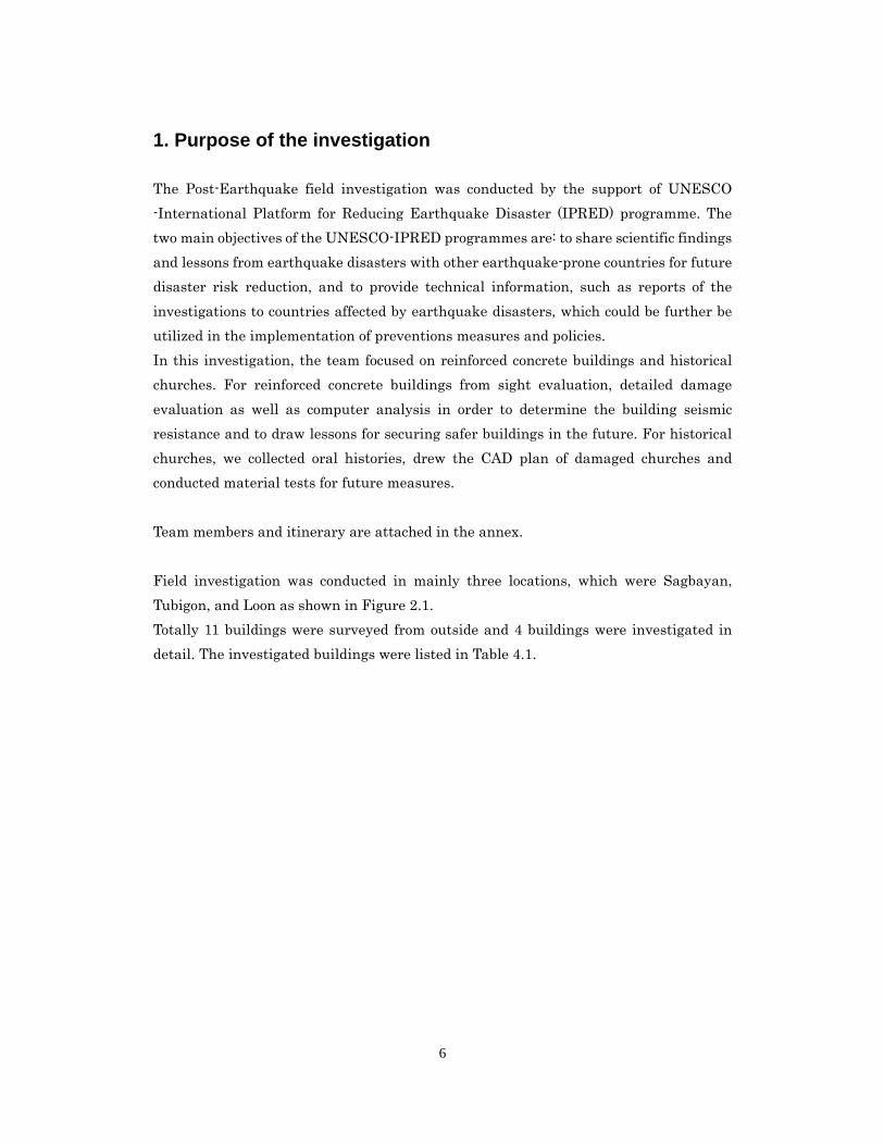
1. Purpose of the investigation
The Post-Earthquake field investigation was conducted by the support of UNESCO
-International Platform for Reducing Earthquake Disaster (IPRED) programme. The
two main objectives of the UNESCO-IPRED programmes are: to share scientific findings
and lessons from earthquake disasters with other earthquake-prone countries for future
disaster risk reduction, and to provide technical information, such as reports of the
investigations to countries affected by earthquake disasters, which could be further be
utilized in the implementation of preventions measures and policies.
In this investigation, the team focused on reinforced concrete buildings and historical
churches. For reinforced concrete buildings from sight evaluation, detailed damage
evaluation as well as computer analysis in order to determine the building seismic
resistance and to draw lessons for securing safer buildings in the future. For historical
churches, we collected oral histories, drew the CAD plan of damaged churches and
conducted material tests for future measures.
Team members and itinerary are attached in the annex.
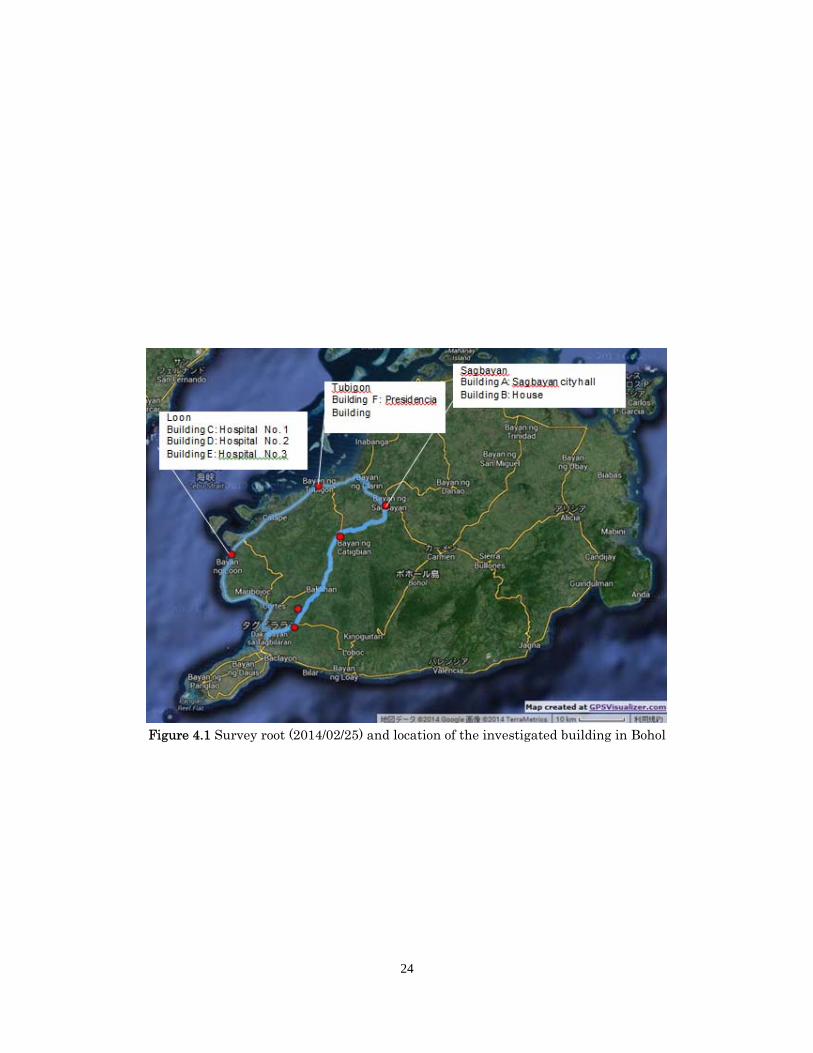
Field investigation was conducted in mainly three locations, which were Sagbayan,
Tubigon, and Loon as shown in Figure 2.1.
Totally 11 buildings were surveyed from outside and 4 buildings were investigated in
detail. The investigated buildings were listed in Table 4.1.
7
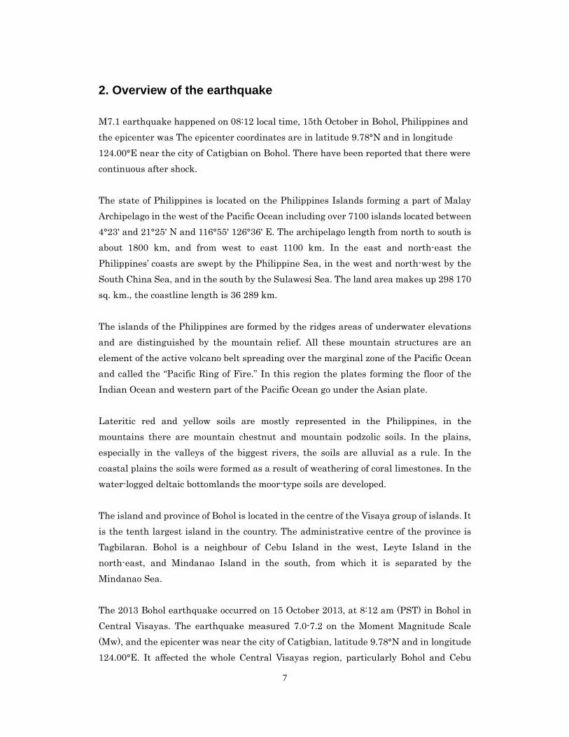
2. Overview of the earthquake
M7.1 earthquake happened on 08:12 local time, 15th October in Bohol, Philippines and
the epicenter was The epicenter coordinates are in latitude 9.78°N and in longitude
124.00°E near the city of Catigbian on Bohol. There have been reported that there were
continuous after shock.
The state of Philippines is located on the Philippines Islands forming a part of Malay
Archipelago in the west of the Pacific Ocean including over 7100 islands located between
4°23' and 21°25' N and 116°55' 126°36' E. The archipelago length from north to south is
about 1800 km, and from west to east 1100 km. In the east and north-east the
Philippines’ coasts are swept by the Philippine Sea, in the west and north-west by the
South China Sea, and in the south by the Sulawesi Sea. The land area makes up 298 170
sq. km., the coastline length is 36 289 km.
The islands of the Philippines are formed by the ridges areas of underwater elevations
and are distinguished by the mountain relief. All these mountain structures are an
element of the active volcano belt spreading over the marginal zone of the Pacific Ocean
and called the “Pacific Ring of Fire.” In this region the plates forming the floor of the
Indian Ocean and western part of the Pacific Ocean go under the Asian plate.
Lateritic red and yellow soils are mostly represented in the Philippines, in the
mountains there are mountain chestnut and mountain podzolic soils. In the plains,
especially in the valleys of the biggest rivers, the soils are alluvial as a rule. In the
coastal plains the soils were formed as a result of weathering of coral limestones. In the
water-logged deltaic bottomlands the moor-type soils are developed.
The island and province of Bohol is located in the centre of the Visaya group of islands. It
is the tenth largest island in the country. The administrative centre of the province is
Tagbilaran. Bohol is a neighbour of Cebu Island in the west, Leyte Island in the
north-east, and Mindanao Island in the south, from which it is separated by the
Mindanao Sea.
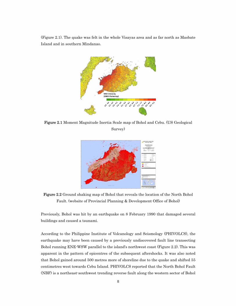
The 2013 Bohol earthquake occurred on 15 October 2013, at 8:12 am (PST) in Bohol in
Central Visayas. The earthquake measured 7.0-7.2 on the Moment Magnitude Scale
(Mw), and the epicenter was near the city of Catigbian, latitude 9.78°N and in longitude
124.00°E. It affected the whole Central Visayas region, particularly Bohol and Cebu
8
(Figure 2.1). The quake was felt in the whole Visayas area and as far north as Masbate
Island and in southern Mindanao.
Figure 2.1 Moment Magnitude Inertia Scale map of Bohol and Cebu. (US Geological
Survey)
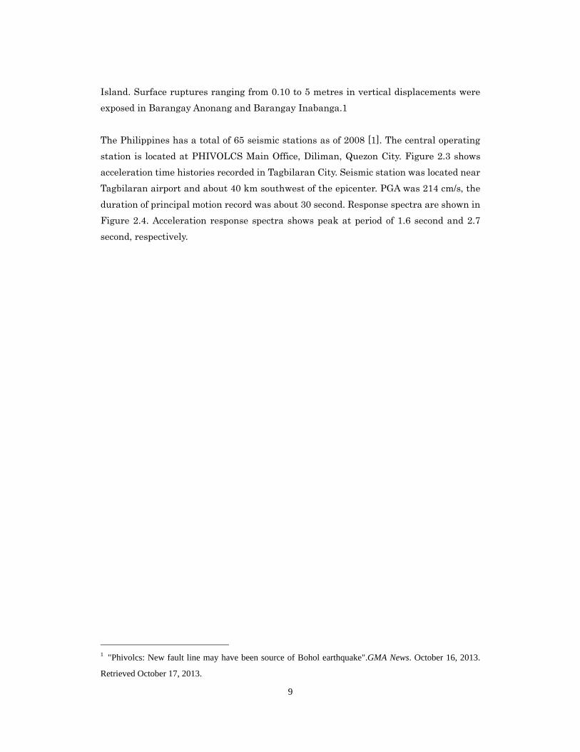
Figure 2.2 Ground shaking map of Bohol that reveals the location of the North Bohol
Fault. (website of Provincial Planning & Development Office of Bohol)
Previously, Bohol was hit by an earthquake on 8 February 1990 that damaged several
buildings and caused a tsunami.
According to the Philippine Institute of Volcanology and Seismology (PHIVOLCS), the
earthquake may have been caused by a previously undiscovered fault line transecting
Bohol running ENE-WSW parallel to the island's northwest coast (Figure 2.2). This was
apparent in the pattern of epicentres of the subsequent aftershocks. It was also noted
that Bohol gained around 500 metres more of shoreline due to the quake and shifted 55
centimetres west towards Cebu Island. PHIVOLCS reported that the North Bohol Fault
(NBF) is a northeast-southwest trending reverse fault along the western sector of Bohol
9
Island. Surface ruptures ranging from 0.10 to 5 metres in vertical displacements were
exposed in Barangay Anonang and Barangay Inabanga.1
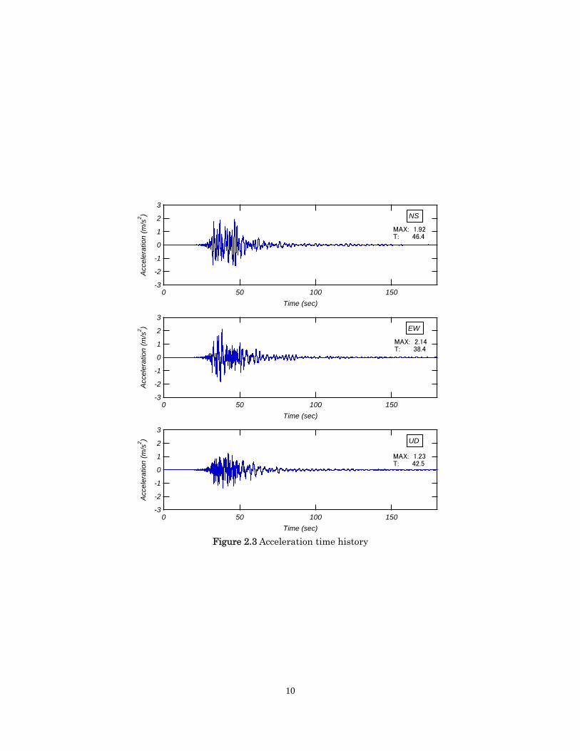
The Philippines has a total of 65 seismic stations as of 2008 [1]. The central operating
station is located at PHIVOLCS Main Office, Diliman, Quezon City. Figure 2.3 shows
acceleration time histories recorded in Tagbilaran City. Seismic station was located near
Tagbilaran airport and about 40 km southwest of the epicenter. PGA was 214 cm/s, the
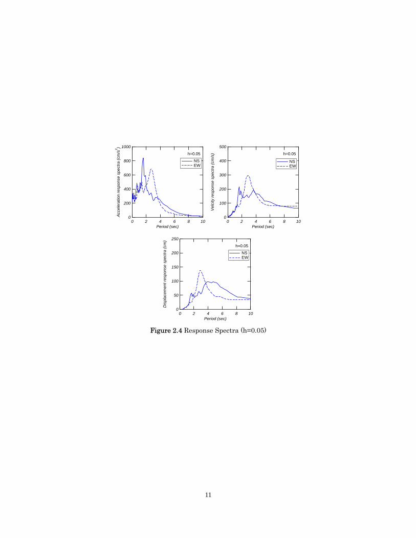
duration of principal motion record was about 30 second. Response spectra are shown in
Figure 2.4. Acceleration response spectra shows peak at period of 1.6 second and 2.7
second, respectively.
1 "Phivolcs: New fault line may have been source of Bohol earthquake".GMA News. October 16, 2013.
Retrieved October 17, 2013.
10
Figure 2.3 Acceleration time history
-3
-2
-1
0
1
2
3
Acc
ele
ratio
n (m
/s2)
150100500
Time (sec)
NS
MAX: 1.92T: 46.4
-3
-2
-1
0
1
2
3
Acc
ele
ratio
n (m
/s2)
150100500
Time (sec)
EW
MAX: 2.14T: 38.4
-3
-2
-1
0
1
2
3
Acc
ele
ratio
n (
m/s
2)
150100500
Time (sec)
UD
MAX: 1.23T: 42.5
11
Figure 2.4 Response Spectra (h=0.05)
1000
800
600
400
200
0Acc
eler
atio
n re
spon
se s
pect
ra (
cm/s
2 )
1086420Period (sec)
NS EW
h=0.05
500
400
300
200
100
0V
elci
ty r
esp
onse
spe
ctra
(cm
/s)
1086420Period (sec)
NS EW
h=0.05
250
200
150
100
50
0
Dis
plac
emen
t res
pons
e sp
ectr
a (c
m)
1086420Period (sec)
NS EW
h=0.05
12
3. Seismic Evaluation Tools
In this section, Post-earthquake Damage Evaluation of reinforced concrete structures,
which is used for the existing buildings after an earthquake, Standard for seismic
evaluation of the existing reinforced concrete buildings, which is also for the existing
buildings but before an earthquake, and numerical analysis tools, which is used for new
buildings, are introduced.
3.1 Outline of Post-earthquake Damage Evaluation in Japan
The Post-earthquake Damage Evaluation method in "Guideline for Post-earthquake
Damage Evaluation and Rehabilitation" [1] is introduced in this section.
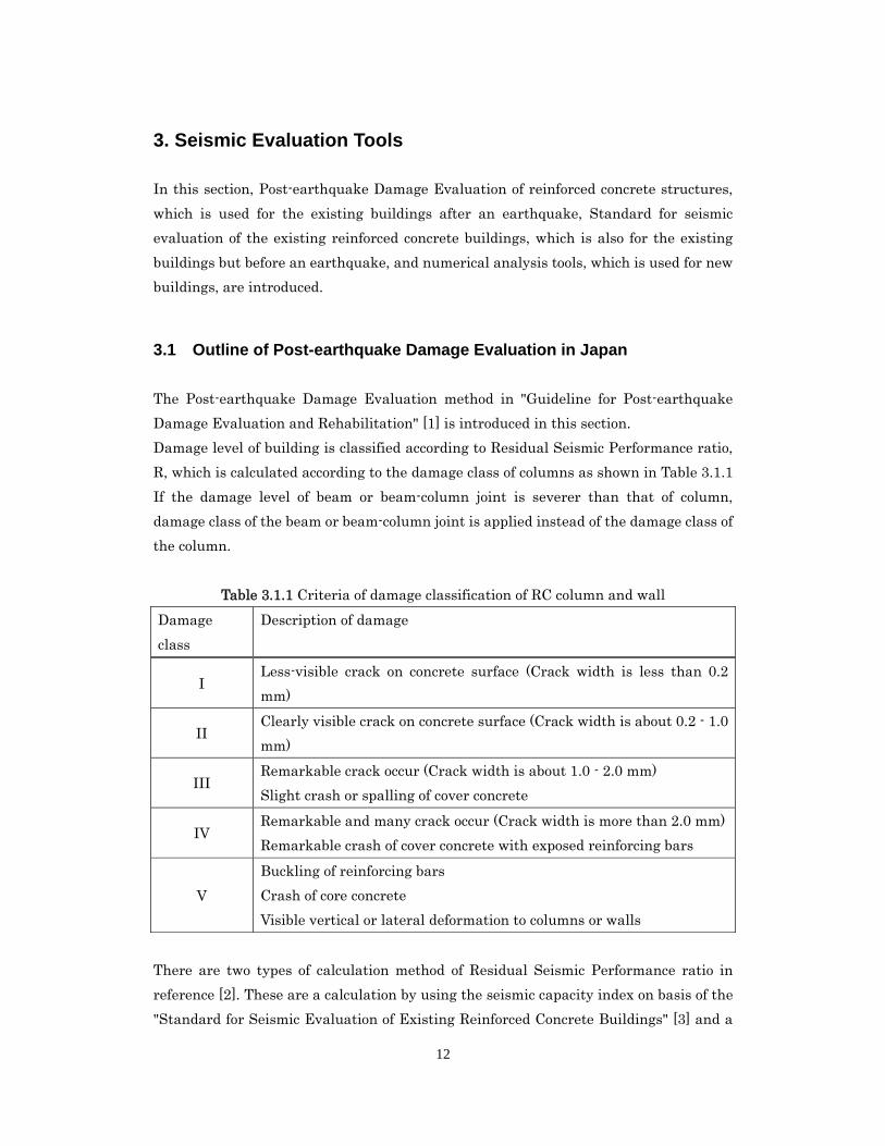
Damage level of building is classified according to Residual Seismic Performance ratio,
R, which is calculated according to the damage class of columns as shown in Table 3.1.1
If the damage level of beam or beam-column joint is severer than that of column,
damage class of the beam or beam-column joint is applied instead of the damage class of
the column.
Table 3.1.1 Criteria of damage classification of RC column and wall
Damage
class
Description of damage
I Less-visible crack on concrete surface (Crack width is less than 0.2
mm)
II Clearly visible crack on concrete surface (Crack width is about 0.2 - 1.0
mm)
III Remarkable crack occur (Crack width is about 1.0 - 2.0 mm)
Slight crash or spalling of cover concrete
IV Remarkable and many crack occur (Crack width is more than 2.0 mm)
Remarkable crash of cover concrete with exposed reinforcing bars
V
Buckling of reinforcing bars
Crash of core concrete
Visible vertical or lateral deformation to columns or walls
There are two types of calculation method of Residual Seismic Performance ratio in
reference [2]. These are a calculation by using the seismic capacity index on basis of the
"Standard for Seismic Evaluation of Existing Reinforced Concrete Buildings" [3] and a
13
simplified calculation. The simplified calculation method of Residual Seismic
Performance ratio of R is drawn below.
(%)100 org
j
A
AR
where
000000 62 CWCCWWMSA
111111 7.59.195.095.095.0 CWCCWWMSA
222222 6.32.16.075.06.0 CWCCWWMSA
333333 8.16.03.05.03.0 CWCCWWMSA
44 1.0 MA
05 A
sumsumsumsumsumorg CWCCWWMSA 62
:,,,,,, 543210 sumSSSSSSS
Number of each shear column judged as damage class of 0 - V and total of them
:,,,,,, 543210 sumMMMMMMM
Number of each flexural column judged as damage class of 0 - V and total of them
:,,,,,, 543210 sumWWWWWWW
Number of each wall without boundary column judged as damage class of 0 - V and total
of them
:,,,,,, 543210 sumCWCWCWCWCWCWCW
Number of each wall with column on one side judged as damage class of 0 - V and total
of them
:,,,,,, 543210 sumCWCCWCCWCCWCCWCCWCCWC
Number of each wall with columns on both side judged as damage class of 0 - V and total
of them
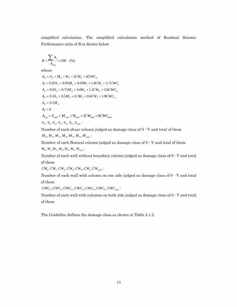
The Guideline defines the damage class as shown in Table 3.1.2.
14
Table 3.1.2 Damage class of building according to
The Residual Seismic Performance ratio: R
Damage class
Slight 95 % ≦ R
Minor 80 % ≦ R < 95 %
Moderate 60 % ≦ R < 80 %
severe ≦ R < 60 %
Collapse Regard as R ≒ 0 due to overall or partial collapse
3.2 Standard for seismic evaluation of the existing reinforced concrete
buildings
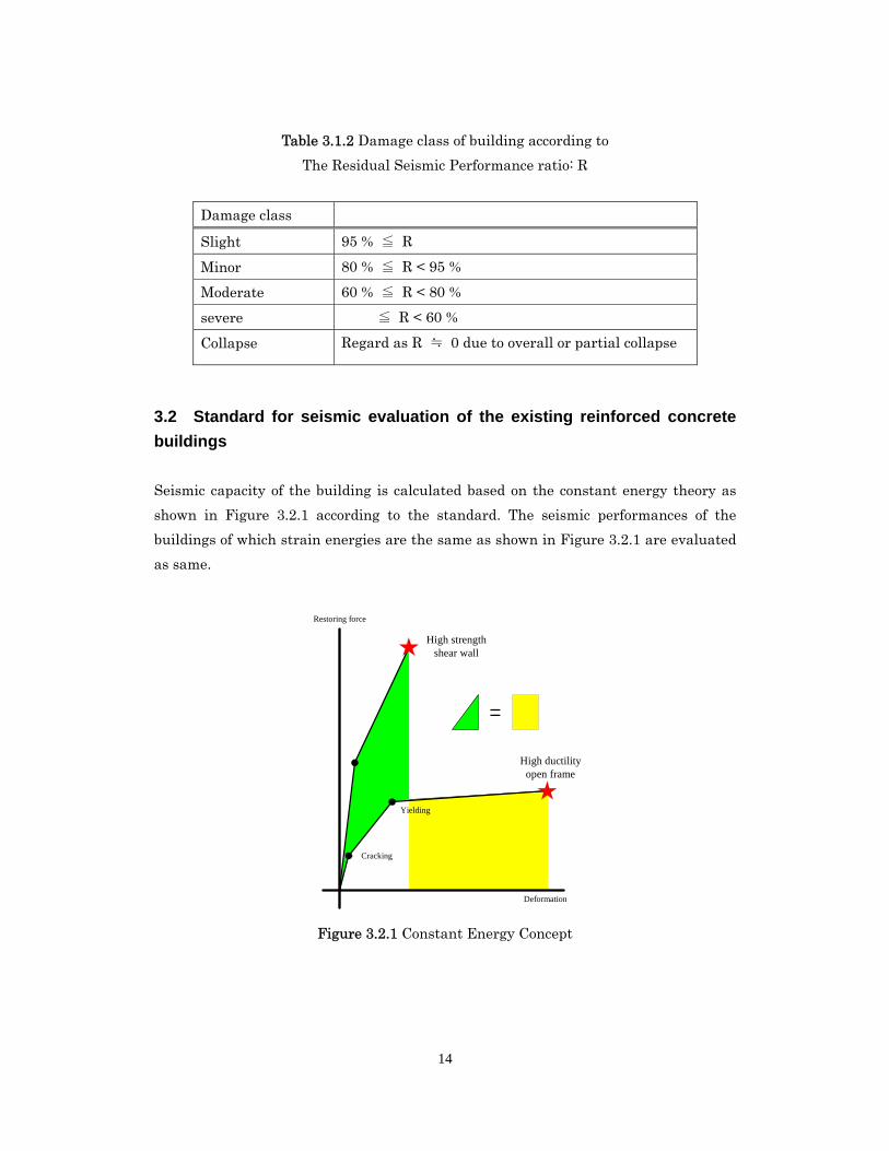
Seismic capacity of the building is calculated based on the constant energy theory as
shown in Figure 3.2.1 according to the standard. The seismic performances of the
buildings of which strain energies are the same as shown in Figure 3.2.1 are evaluated
as same.
Deformation
Restoring force
Cracking
Yielding
High strengthshear wall
High ductilityopen frame
=
Figure 3.2.1 Constant Energy Concept
15
The evaluation is simple as shown in Equation 3.2.1.
soSi II Equation 3.2.1
Where, Si I is the calculated seismic performance index for i-th story, and soI is the
required seismic capacity index.
The seismic performance index Si I , is calculated as equation 3.2.2.
TSEI DiSi 0 Equation 3.2.2
Where 0Ei is seismic capacity index for i-th story, DS is unbalance index, and T is
aging index.
0E is the fundamental index and calculated based on the constant energy theory as
Equation 3.2.3.
FCA
Ei
1
0 Equation 3.2.3
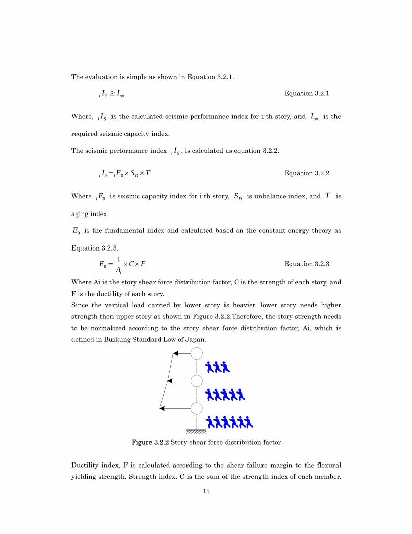
Where Ai is the story shear force distribution factor, C is the strength of each story, and
F is the ductility of each story.
Since the vertical load carried by lower story is heavier, lower story needs higher
strength then upper story as shown in Figure 3.2.2.Therefore, the story strength needs
to be normalized according to the story shear force distribution factor, Ai, which is
defined in Building Standard Low of Japan.
Figure 3.2.2 Story shear force distribution factor
Ductility index, F is calculated according to the shear failure margin to the flexural
yielding strength. Strength index, C is the sum of the strength index of each member.
16
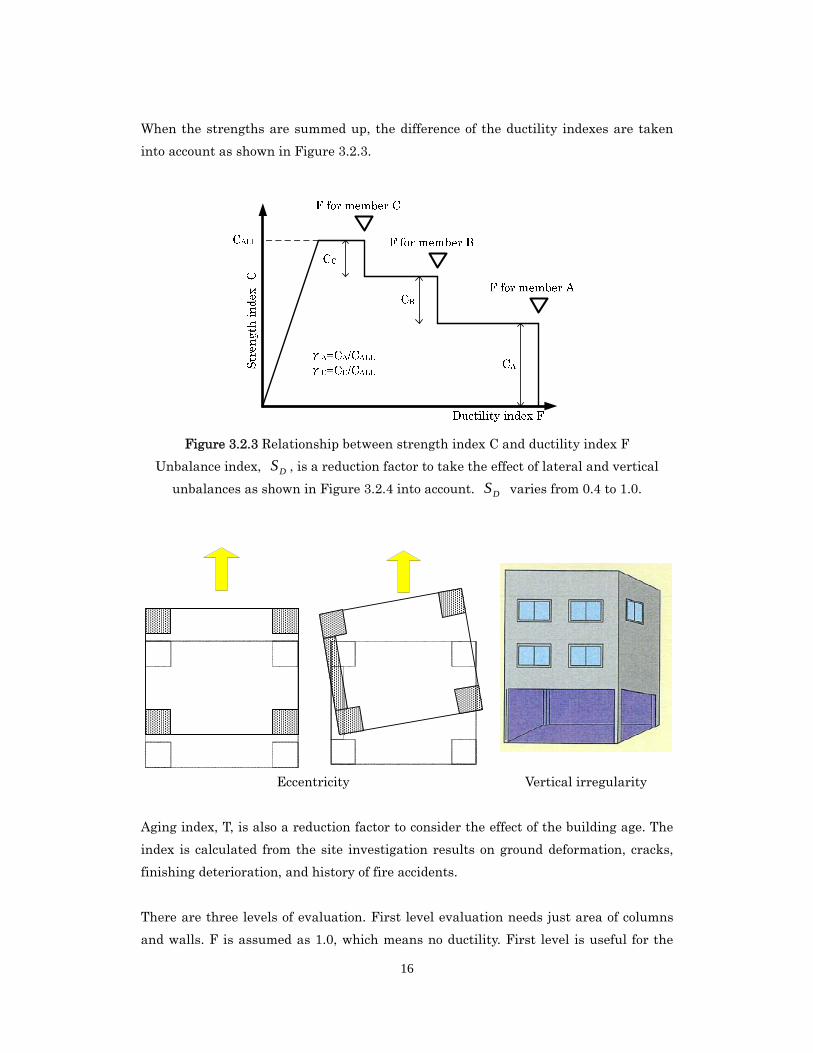
When the strengths are summed up, the difference of the ductility indexes are taken
into account as shown in Figure 3.2.3.
Figure 3.2.3 Relationship between strength index C and ductility index F
Unbalance index, DS , is a reduction factor to take the effect of lateral and vertical
unbalances as shown in Figure 3.2.4 into account. DS varies from 0.4 to 1.0.
Eccentricity Vertical irregularity
Aging index, T, is also a reduction factor to consider the effect of the building age. The
index is calculated from the site investigation results on ground deformation, cracks,
finishing deterioration, and history of fire accidents.
There are three levels of evaluation. First level evaluation needs just area of columns
and walls. F is assumed as 1.0, which means no ductility. First level is useful for the
17
buildings of which drawings are missing and bar arrangements in members are
unknown. The result of the first level is the most conservative.
The second level evaluation consider the ultimate strength, failure mode, and ductility
of columns. Girders are considered rigid and strong enough. The third level evaluation
consider those of the girders, too. The third level evaluation must be applied for the
buildings of which girders are expected to form yielding hinges.
The required seismic capacity index, soI , is calculated as Equation 3.2.4.
UGZEI SS 0 Equation 3.2.4
Where SE is the basic seismic capacity evaluation index, 0.8 for the first level
evaluation and 0.6 for the second and third level evaluations. Z is the zone factor, which
is a reduction factor according to the seismic activity at the site defined in Building
Standard Low in Japan. G is the soil condition factor and U is importance factor.
The Japanese central government set the target to finish the evaluation and retrofitting
if needed of 90% of the existing buildings by Y2015. The Building Standard Low of
Japan had been revised in 1981. After that, ultimate capacities of all existing buildings
need to be evaluated. Therefore, the “standard for seismic evaluation of the existing
reinforced concrete buildings” is basically applied for the existing buildings that were
designed before 1981. As of 2008, about 80% of the existing buildings were evaluated
and retrofitted if needed.
3.3 Computer analysis tools
3.3.1 Modeling of building
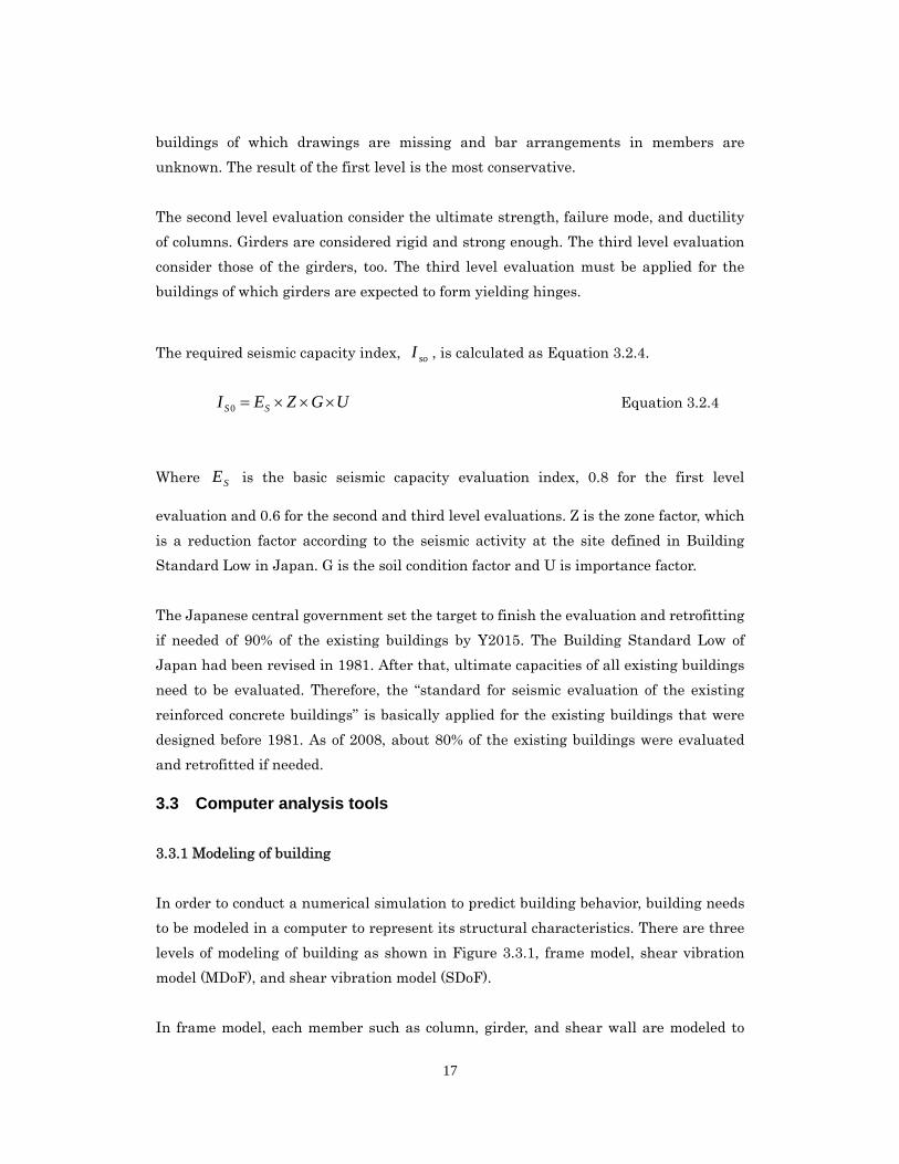
In order to conduct a numerical simulation to predict building behavior, building needs
to be modeled in a computer to represent its structural characteristics. There are three
levels of modeling of building as shown in Figure 3.3.1, frame model, shear vibration
model (MDoF), and shear vibration model (SDoF).
In frame model, each member such as column, girder, and shear wall are modeled to
18
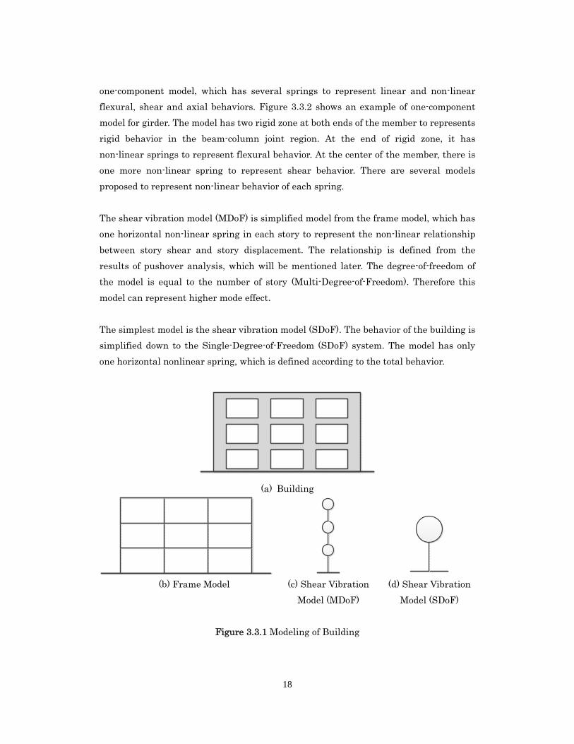
one-component model, which has several springs to represent linear and non-linear
flexural, shear and axial behaviors. Figure 3.3.2 shows an example of one-component
model for girder. The model has two rigid zone at both ends of the member to represents
rigid behavior in the beam-column joint region. At the end of rigid zone, it has
non-linear springs to represent flexural behavior. At the center of the member, there is
one more non-linear spring to represent shear behavior. There are several models
proposed to represent non-linear behavior of each spring.
The shear vibration model (MDoF) is simplified model from the frame model, which has
one horizontal non-linear spring in each story to represent the non-linear relationship
between story shear and story displacement. The relationship is defined from the
results of pushover analysis, which will be mentioned later. The degree-of-freedom of
the model is equal to the number of story (Multi-Degree-of-Freedom). Therefore this
model can represent higher mode effect.
The simplest model is the shear vibration model (SDoF). The behavior of the building is
simplified down to the Single-Degree-of-Freedom (SDoF) system. The model has only
one horizontal nonlinear spring, which is defined according to the total behavior.
(a) Building
(b) Frame Model (c) Shear Vibration
Model (MDoF)
(d) Shear Vibration
Model (SDoF)
Figure 3.3.1 Modeling of Building
19
Figure 3.3.2 Example of one-component model (for girder)
3.3.2 Time History Analysis
Once the building is modeled, several kind of analysis can be conducted with the model.
Time history analysis can reproduce the response behavior of the building under an
earthquake input. During the analysis, the motion of equation is solved to calculate the
responses at each time step. Time history of input motion is needed for this analysis. If
the input motion can be defined, this analysis method is the most accurate to predict
actual behavior during an earthquake. The results is, however, depending on the input
motion. Careful attention must be paid that a different input motion can give different
results.
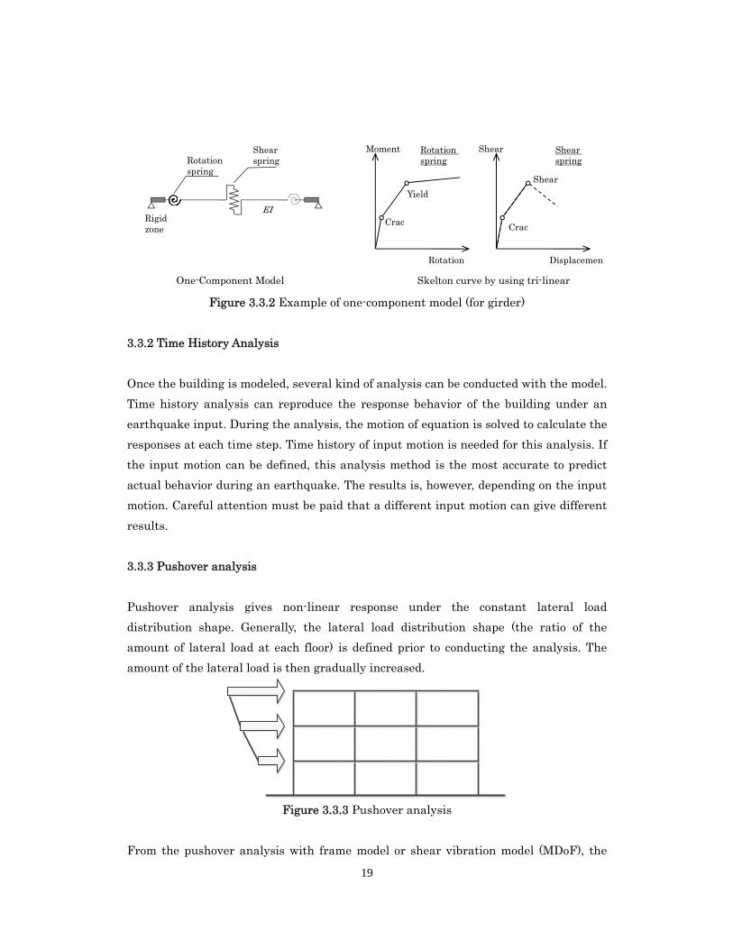
3.3.3 Pushover analysis
Pushover analysis gives non-linear response under the constant lateral load
distribution shape. Generally, the lateral load distribution shape (the ratio of the
amount of lateral load at each floor) is defined prior to conducting the analysis. The
amount of the lateral load is then gradually increased.
Figure 3.3.3 Pushover analysis
From the pushover analysis with frame model or shear vibration model (MDoF), the
Rotation
Rigid zone
One-Component Model
Moment Rotation spring
Shear spring
Skelton curve by using tri-linear
Rotation spring
Displacemen
Shear Shear spring
Crac Crac
Yield
Shear
EI
20
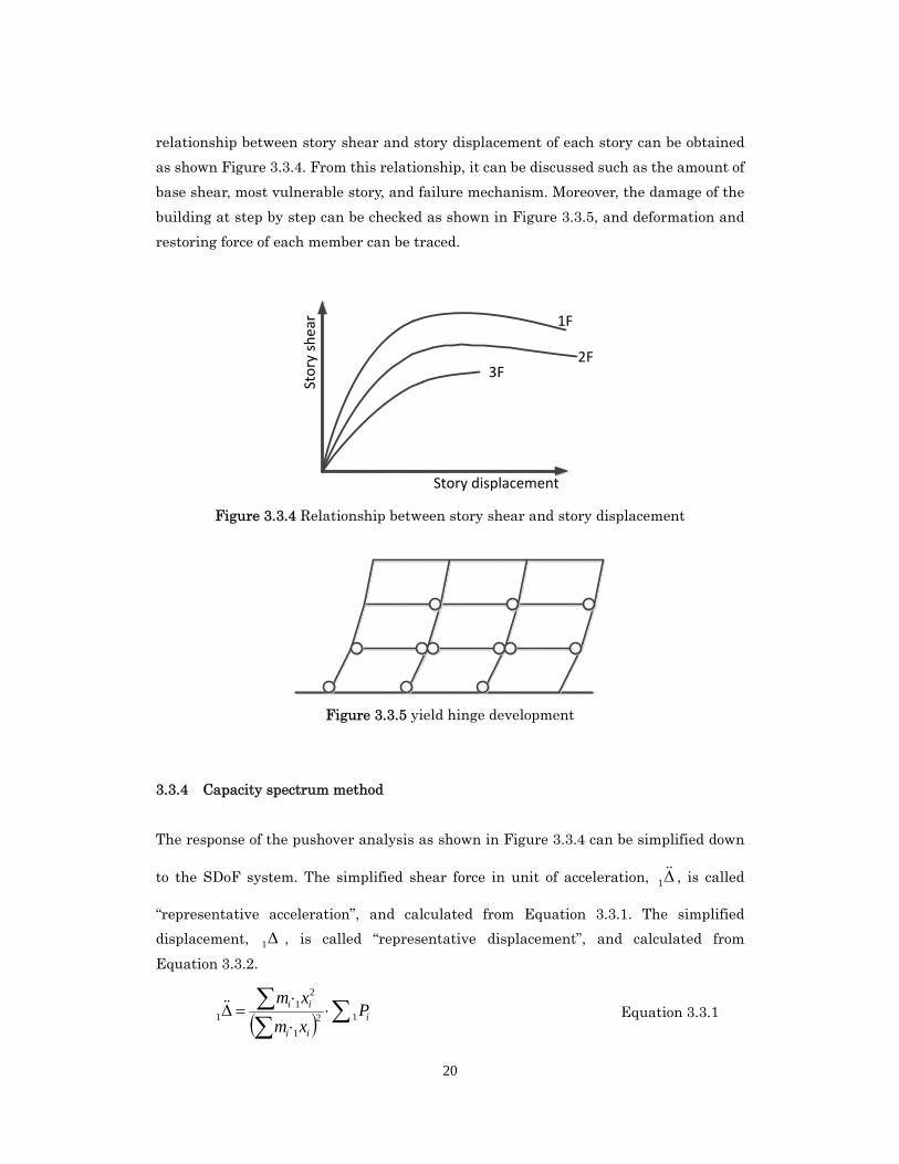
relationship between story shear and story displacement of each story can be obtained
as shown Figure 3.3.4. From this relationship, it can be discussed such as the amount of
base shear, most vulnerable story, and failure mechanism. Moreover, the damage of the
building at step by step can be checked as shown in Figure 3.3.5, and deformation and
restoring force of each member can be traced.
Sto
ry s
he
ar
Story displacement
1F
2F3F
Figure 3.3.4 Relationship between story shear and story displacement
Figure 3.3.5 yield hinge development
3.3.4 Capacity spectrum method
The response of the pushover analysis as shown in Figure 3.3.4 can be simplified down
to the SDoF system. The simplified shear force in unit of acceleration, 1 , is called
“representative acceleration”, and calculated from Equation 3.3.1. The simplified
displacement, 1 , is called “representative displacement”, and calculated from
Equation 3.3.2.
i
ii
ii Pxm
xm12
1
21
1 Equation 3.3.1
21
ii
ii
xm
xm
1
21
1 Equation 3.3.2
Where;
im Mass at i-th story
ix1 Relative displacement at i-th floor to the base of the building
iP1 Amount of lateral force acting at i-th floor
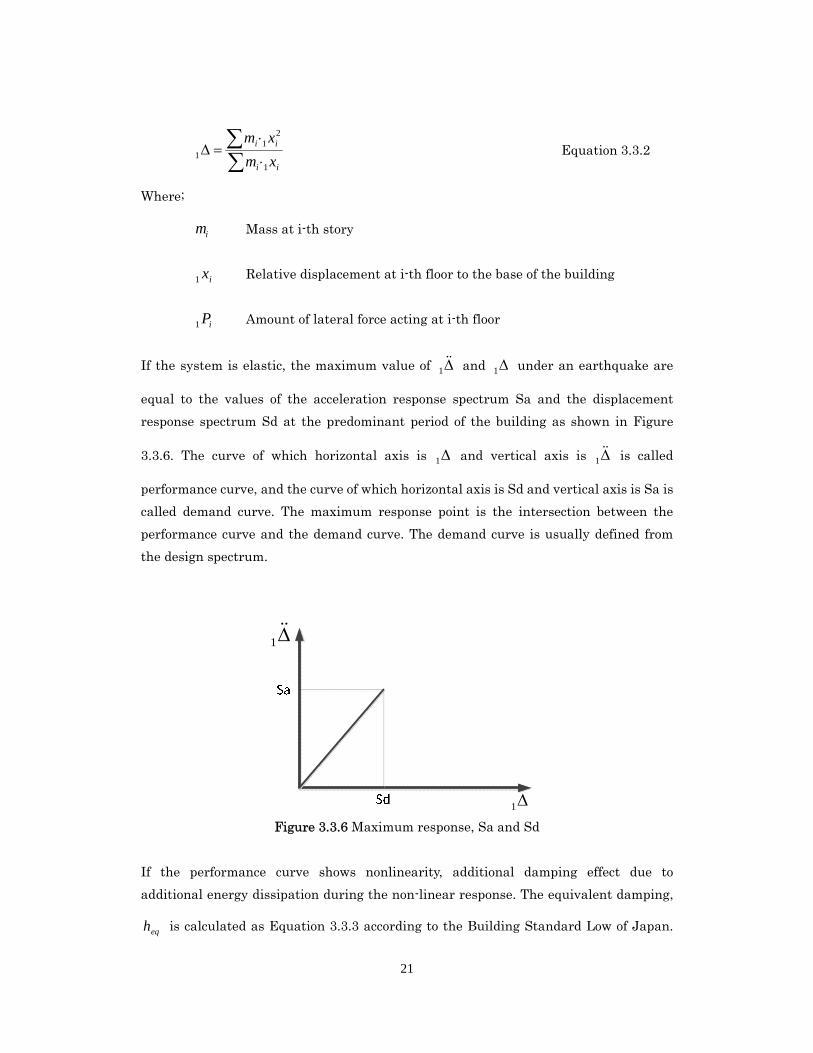
If the system is elastic, the maximum value of 1 and 1 under an earthquake are
equal to the values of the acceleration response spectrum Sa and the displacement
response spectrum Sd at the predominant period of the building as shown in Figure
3.3.6. The curve of which horizontal axis is 1 and vertical axis is 1 is called
performance curve, and the curve of which horizontal axis is Sd and vertical axis is Sa is
called demand curve. The maximum response point is the intersection between the
performance curve and the demand curve. The demand curve is usually defined from
the design spectrum.
1
1 Figure 3.3.6 Maximum response, Sa and Sd
If the performance curve shows nonlinearity, additional damping effect due to
additional energy dissipation during the non-linear response. The equivalent damping,
eqh is calculated as Equation 3.3.3 according to the Building Standard Low of Japan.
22
The viscous damping of 5% is considered.
05.01
1
eqh Equation 3.3.3
Where;
=0.20 or 0.25 according to the structural characteristics
yielding factor
The demand reduction factor due to the nonlinearity, hF is calculated as Equation
3.3.4.
eq
h hF
101
5.1
Equation 3.3.4
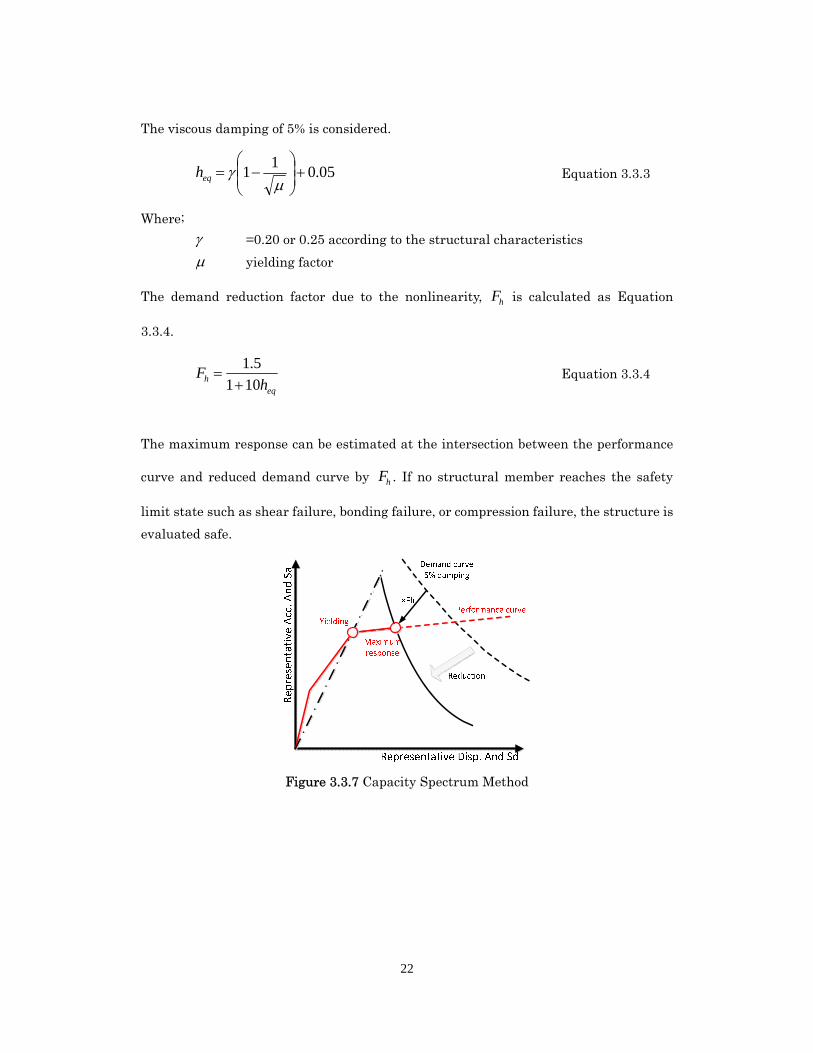
The maximum response can be estimated at the intersection between the performance
curve and reduced demand curve by hF . If no structural member reaches the safety
limit state such as shear failure, bonding failure, or compression failure, the structure is
evaluated safe.
Figure 3.3.7 Capacity Spectrum Method
23
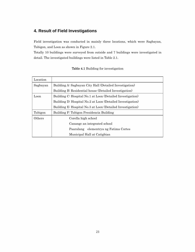
4. Result of Field Investigations
Field investigation was conducted in mainly three locations, which were Sagbayan,
Tubigon, and Loon as shown in Figure 2.1.
Totally 10 buildings were surveyed from outside and 7 buildings were investigated in
detail. The investigated buildings were listed in Table 2.1.
Table 4.1 Building for investigation
Location
Sagbayan Building A: Sagbayan City Hall (Detailed Investigation)
Building B: Residential house (Detailed Investigation)
Loon Building C: Hospital No.1 at Loon (Detailed Investigation)
Building D: Hospital No.2 at Loon (Detailed Investigation)
Building E: Hospital No.3 at Loon (Detailed Investigation)
Tubigon Building F: Tubigon Presidencia Building
Others Corella high school
Canangc an integrated school
Paaralang elementrya ng Fatima Cortes
Municipal Hall at Catigbian
24
Figure 4.1 Survey root (2014/02/25) and location of the investigated building in Bohol
25
4.1 Building A: Sagbayan city hall (at Sagbayan)
4.1.1 Outline of building damage
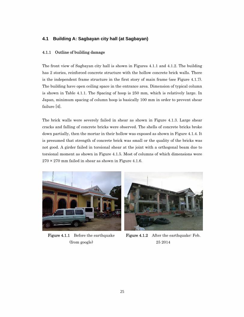
The front view of Sagbayan city hall is shown in Figures 4.1.1 and 4.1.2. The building
has 2 stories, reinforced concrete structure with the hollow concrete brick walls. There
is the independent frame structure in the first story of main frame (see Figure 4.1.7).
The building have open ceiling space in the entrance area. Dimension of typical column
is shown in Table 4.1.1. The Spacing of hoop is 250 mm, which is relatively large. In
Japan, minimum spacing of column hoop is basically 100 mm in order to prevent shear
failure [4].
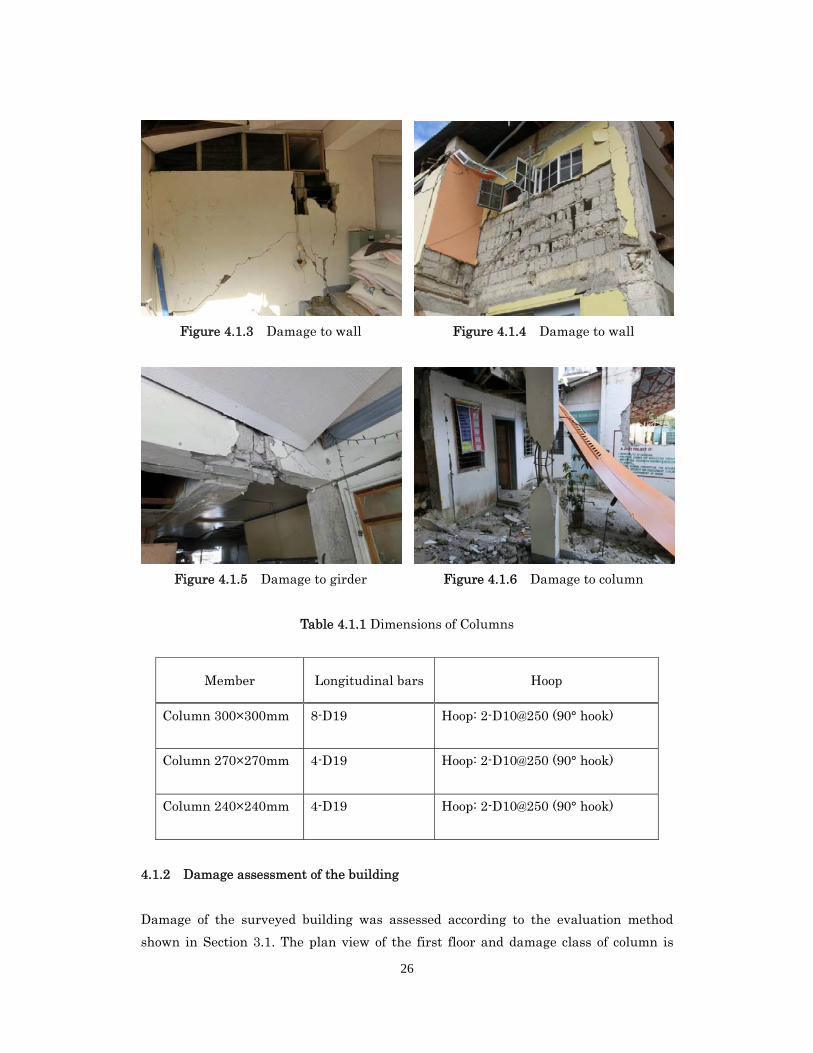
The brick walls were severely failed in shear as shown in Figure 4.1.3. Large shear
cracks and falling of concrete bricks were observed. The shells of concrete bricks broke
down partially, then the mortar in their hollow was exposed as shown in Figure 4.1.4. It
is presumed that strength of concrete brick was small or the quality of the bricks was
not good. A girder failed in torsional shear at the joint with a orthogonal beam due to
torsional moment as shown in Figure 4.1.5. Most of columns of which dimensions were
270 × 270 mm failed in shear as shown in Figure 4.1.6.
Figure 4.1.1 Before the earthquake
(from google)
Figure 4.1.2 After the earthquake: Feb.
25 2014
26
Figure 4.1.3 Damage to wall Figure 4.1.4 Damage to wall
Figure 4.1.5 Damage to girder Figure 4.1.6 Damage to column
Table 4.1.1 Dimensions of Columns
Member Longitudinal bars Hoop
Column 300×300mm 8-D19 Hoop: 2-D10@250 (90° hook)
Column 270×270mm 4-D19 Hoop: 2-D10@250 (90° hook)
Column 240×240mm 4-D19 Hoop: 2-D10@250 (90° hook)
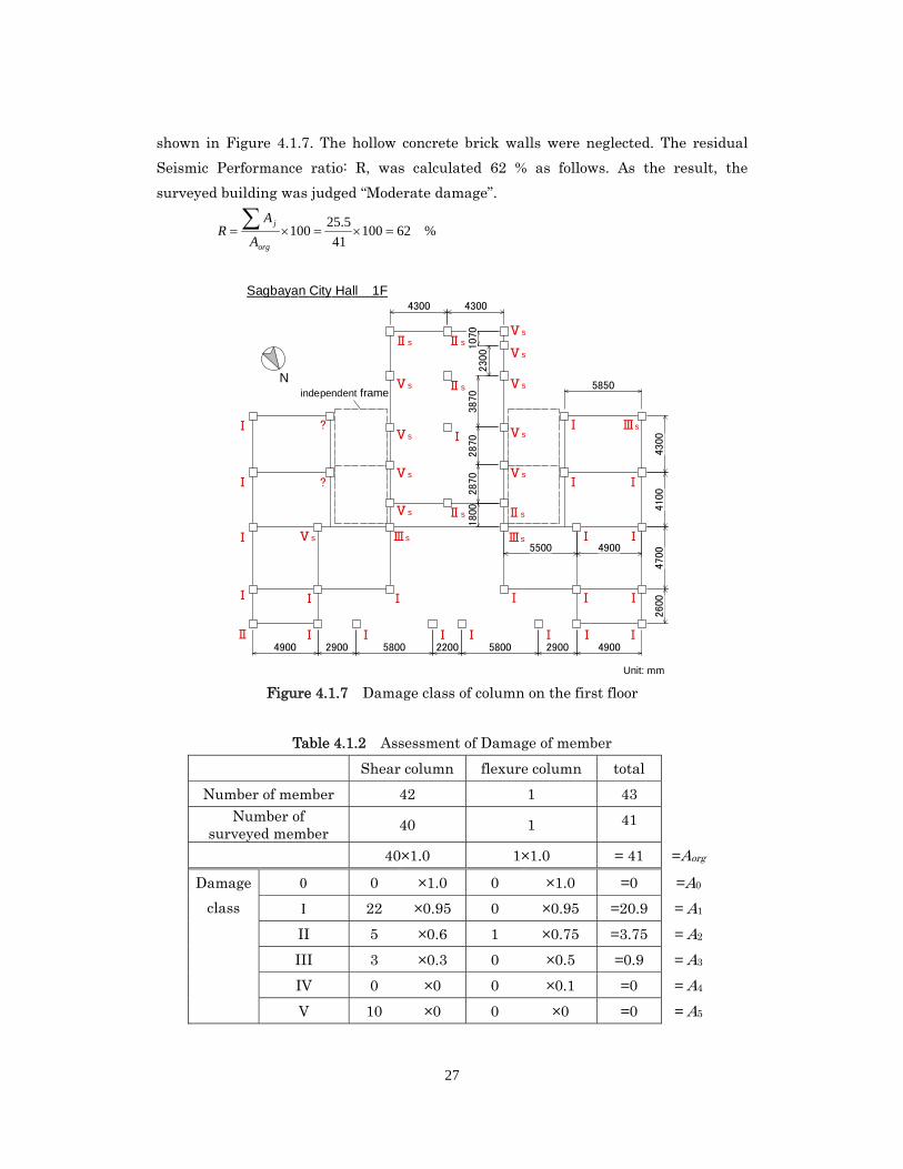
4.1.2 Damage assessment of the building
Damage of the surveyed building was assessed according to the evaluation method
shown in Section 3.1. The plan view of the first floor and damage class of column is
27
shown in Figure 4.1.7. The hollow concrete brick walls were neglected. The residual
Seismic Performance ratio: R, was calculated 62 % as follows. As the result, the
surveyed building was judged “Moderate damage”.
%6210041
5.25100
org
j
A
AR
Figure 4.1.7 Damage class of column on the first floor
Table 4.1.2 Assessment of Damage of member
Shear column flexure column total
Number of member 42 1 43 Number of
surveyed member 40 1 41
40×1.0 1×1.0 = 41 =Aorg
Damage
class
0 ×1.0 0 ×1.0 =0 =A0
22 ×0.95 0 ×0.95 =20.9 = A1
II 5 ×0.6 1 ×0.75 =3.75 = A2
III 3 ×0.3 0 ×0.5 =0.9 = A3
IV 0 ×0 0 ×0.1 =0 = A4
V 10 ×0 0 ×0 =0 = A5
Sagbayan City Hall 1F
N
2600
4700
4100
4300
4900 2900 5800 2200 5800 2900 4900
5850
5500 4900
1800
2870
2870
3870
23001070
4300 4300
independent frame
Ⅰ
Ⅰ
Ⅰ
Ⅰ
Ⅱ Ⅰ
Ⅰ
Ⅴs
?
?
Ⅰ Ⅰ Ⅰ Ⅰ
ⅠⅠⅠⅠ
Ⅲs
Ⅴs
Ⅴs
Ⅴs
Ⅴs
Ⅱs Ⅱs
Ⅴs
Ⅴs
Ⅴs
Ⅱs
Ⅰ
Ⅱs Ⅱs
Ⅲs
Ⅴs
Ⅴs
Ⅰ Ⅰ
Ⅰ Ⅰ
Ⅰ Ⅲs
Ⅰ Ⅰ
Unit: mm
28
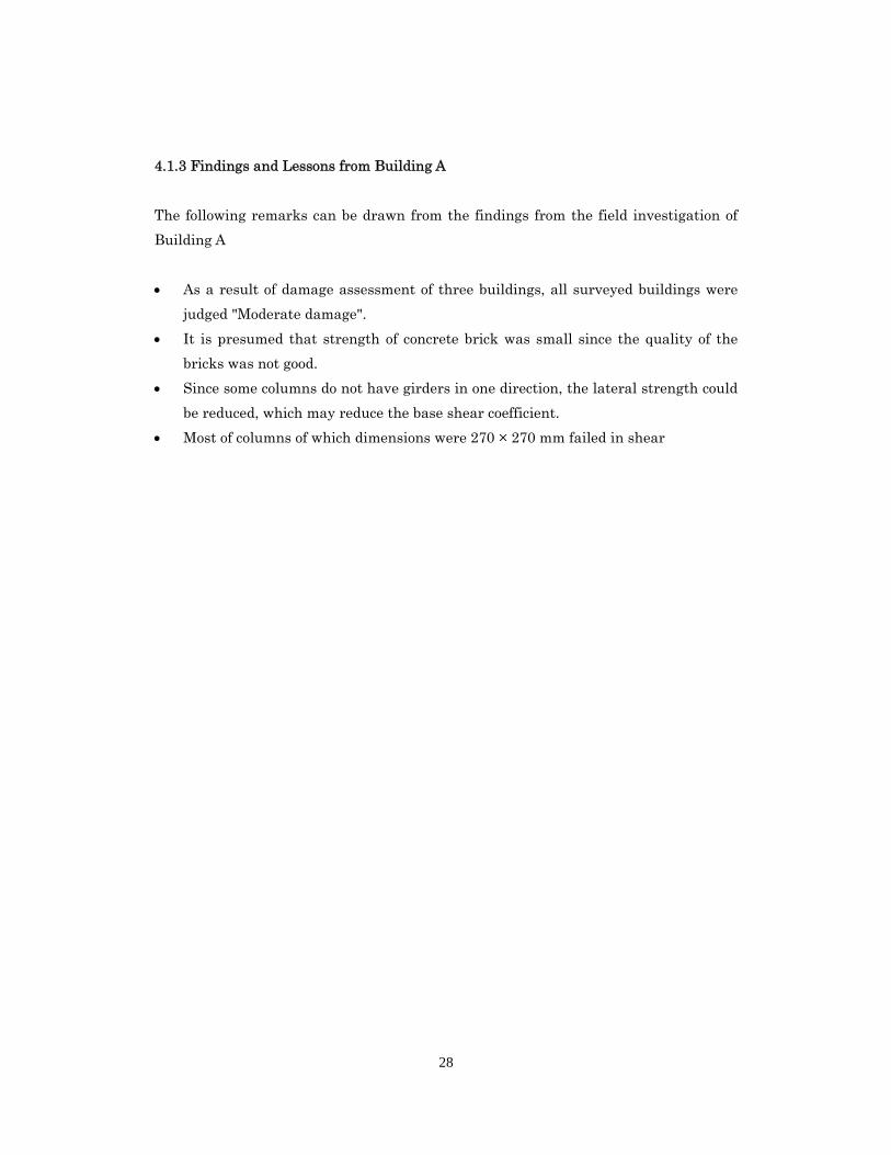
4.1.3 Findings and Lessons from Building A
The following remarks can be drawn from the findings from the field investigation of
Building A
As a result of damage assessment of three buildings, all surveyed buildings were
judged "Moderate damage".
It is presumed that strength of concrete brick was small since the quality of the
bricks was not good.
Since some columns do not have girders in one direction, the lateral strength could
be reduced, which may reduce the base shear coefficient.
Most of columns of which dimensions were 270 × 270 mm failed in shear
29
4.2 Building B: House (at Sagbayan)
4.2.1 Outline of building damage
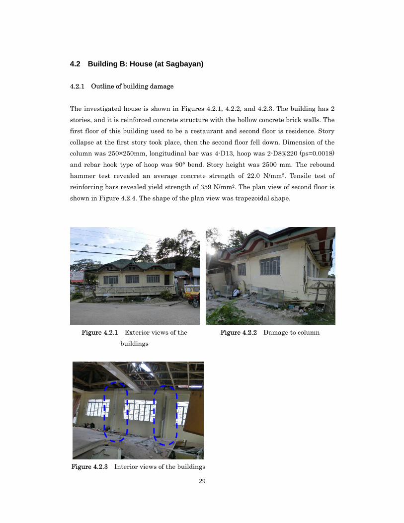
The investigated house is shown in Figures 4.2.1, 4.2.2, and 4.2.3. The building has 2
stories, and it is reinforced concrete structure with the hollow concrete brick walls. The
first floor of this building used to be a restaurant and second floor is residence. Story
collapse at the first story took place, then the second floor fell down. Dimension of the
column was 250×250mm, longitudinal bar was 4-D13, hoop was 2-D8@220 (ps=0.0018)
and rebar hook type of hoop was 90° bend. Story height was 2500 mm. The rebound
hammer test revealed an average concrete strength of 22.0 N/mm2. Tensile test of
reinforcing bars revealed yield strength of 359 N/mm2. The plan view of second floor is
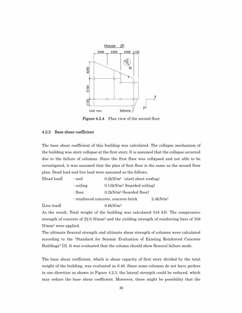
shown in Figure 4.2.4. The shape of the plan view was trapezoidal shape.
Figure 4.2.1 Exterior views of the
buildings
Figure 4.2.2 Damage to column
Figure 4.2.3 Interior views of the buildings
30
Figure 4.2.4 Plan view of the second floor
4.2.2 Base shear coefficient
The base shear coefficient of this building was calculated. The collapse mechanism of
the building was story collapse at the first story. It is assumed that the collapse occurred
due to the failure of columns. Since the first floor was collapsed and not able to be
investigated, it was assumed that the plan of first floor is the same as the second floor
plan. Dead load and live load were assumed as the follows.
[Dead load] - roof 0.2kN/m2(steel sheet roofing)
- ceiling 0.15kN/m2 (boarded ceiling)
- floor 0.2kN/m2 (boarded floor)
- reinforced concrete, concrete brick 2.4kN/m3
[Live load] 0.6kN/m2
As the result, Total weight of the building was calculated 534 kN. The compressive
strength of concrete of 22.0 N/mm2 and the yielding strength of reinforcing bars of 359
N/mm2 were applied.
The ultimate flexural strength and ultimate shear strength of columns were calculated
according to the "Standard for Seismic Evaluation of Existing Reinforced Concrete
Buildings" [3]. It was evaluated that the column should show flexural failure mode.
The base shear coefficient, which is shear capacity of first story divided by the total
weight of the building, was evaluated as 0.40. Since some columns do not have girders
in one direction as shown in Figure 4.2.3, the lateral strength could be reduced, which
may reduce the base shear coefficient. Moreover, there might be possibility that the
House 2F
N
4250
515
017
25
balcony
3350 3350 3350 1125
?
Unit: mm
x
y
31
amount of the hollow brick walls in the first story might be less than that of the second
story, since the first story was restaurant.
4.2.3 Pushover analysis
Non-linear pushover analysis was conducted. The beams and columns were modeled by
using One-component model. Non-linear shear spring was considered in modeled
column. The foundation was assumed to be fix, and the floor was assumed to be rigid.
The lateral load acted on the building according to Ai distribution calculated from the
following equation.
T
TA i
i
i 31
211
n
j
j
n
ij
j
i
W
W
1
i : Non dimensional weight
Wi : Weight of i-th story
n : Number of story of the building
T : The fundamental natural period (sec)
hT 01.002.0
h : Height of the building (m)
α : Ratio of the height of story, consisting of steel columns and girder, to entire
height h, this means that T = 0.03h for steel structure and T = 0.02h for
concrete structures.
Mass of first story (second floor) and second story (roof floor) were assumed to be 372kN
and 162kN respectively. The loading direction were x and y direction. This analysis was
conducted by using a software of " STERA3D ver.6.0" [5].
Story drift and story shear relations are shown in Figure 4.2.5. Longitudinal axis is
story shear coefficient which story shear is normalized by total weight of the building.
Figure 4.2.6 shows location of plastic hinge in the building. Story shear coefficient at the
first story is about 0.39. Story drift at the first story is considerably larger than that at
the second story, and it is found that plastic hinge develop end of column in first story.
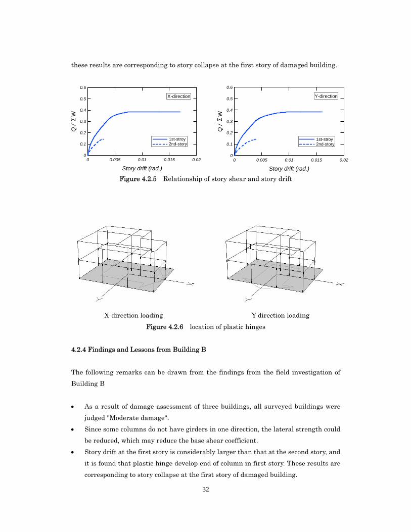
32
these results are corresponding to story collapse at the first story of damaged building.
Figure 4.2.5 Relationship of story shear and story drift
X-direction loading
Y-direction loading
Figure 4.2.6 location of plastic hinges
4.2.4 Findings and Lessons from Building B
The following remarks can be drawn from the findings from the field investigation of
Building B
As a result of damage assessment of three buildings, all surveyed buildings were
judged "Moderate damage".
Since some columns do not have girders in one direction, the lateral strength could
be reduced, which may reduce the base shear coefficient.
Story drift at the first story is considerably larger than that at the second story, and
it is found that plastic hinge develop end of column in first story. These results are
corresponding to story collapse at the first story of damaged building.
0.6
0.5
0.4
0.3
0.2
0.1
0
Q /
ΣW
0.020.0150.010.0050
Story drift (rad.)
1st-stroy 2nd-story
X-direction
0.6
0.5
0.4
0.3
0.2
0.1
0
Q /
ΣW
0.020.0150.010.0050
Story drift (rad.)
1st-stroy 2nd-story
Y-direction
33
4.3 Building C: Hospital No. 1 (at Loon)
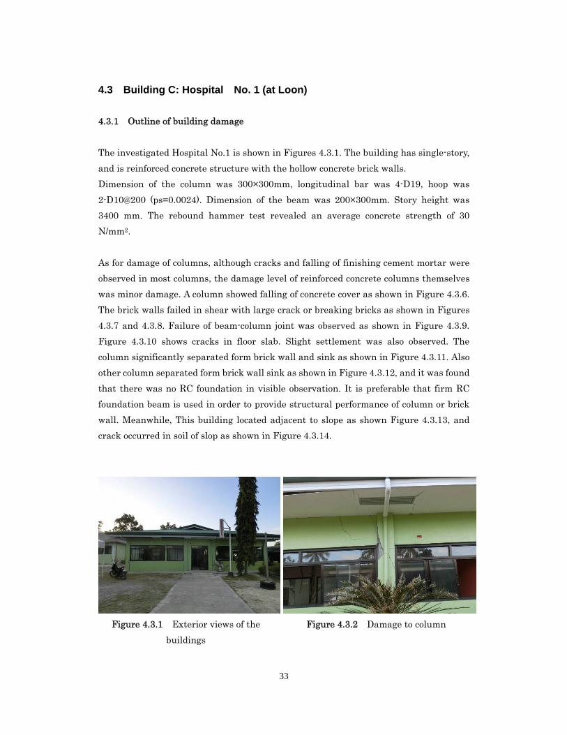
4.3.1 Outline of building damage
The investigated Hospital No.1 is shown in Figures 4.3.1. The building has single-story,
and is reinforced concrete structure with the hollow concrete brick walls.
Dimension of the column was 300×300mm, longitudinal bar was 4-D19, hoop was
2-D10@200 (ps=0.0024). Dimension of the beam was 200×300mm. Story height was
3400 mm. The rebound hammer test revealed an average concrete strength of 30
N/mm2.
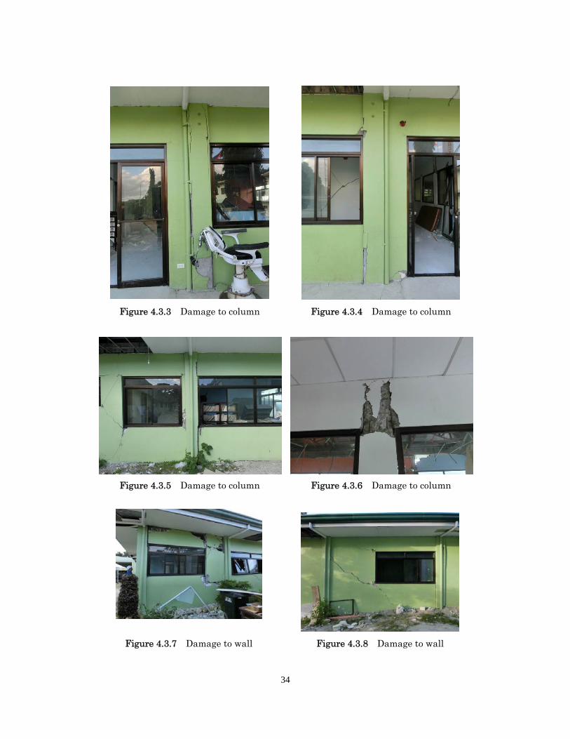
As for damage of columns, although cracks and falling of finishing cement mortar were
observed in most columns, the damage level of reinforced concrete columns themselves
was minor damage. A column showed falling of concrete cover as shown in Figure 4.3.6.
The brick walls failed in shear with large crack or breaking bricks as shown in Figures
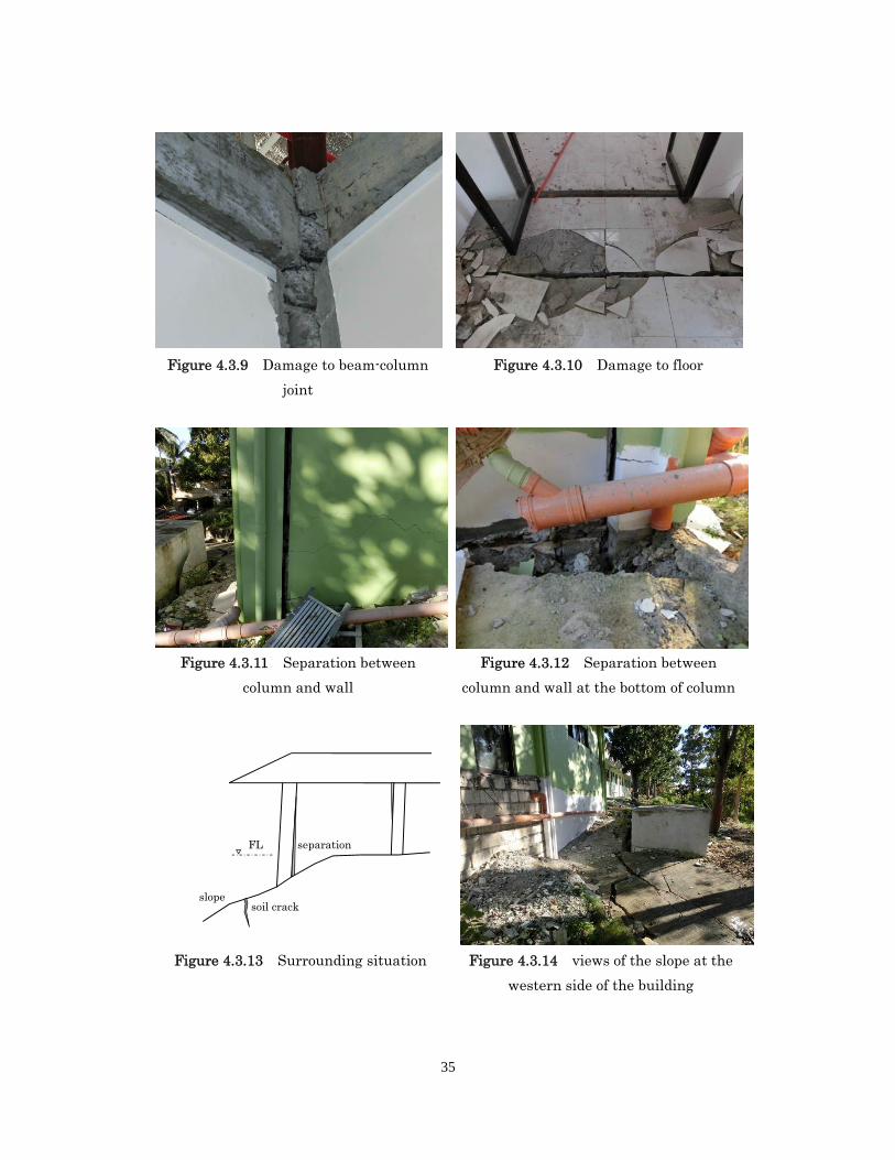
4.3.7 and 4.3.8. Failure of beam-column joint was observed as shown in Figure 4.3.9.
Figure 4.3.10 shows cracks in floor slab. Slight settlement was also observed. The
column significantly separated form brick wall and sink as shown in Figure 4.3.11. Also
other column separated form brick wall sink as shown in Figure 4.3.12, and it was found
that there was no RC foundation in visible observation. It is preferable that firm RC
foundation beam is used in order to provide structural performance of column or brick
wall. Meanwhile, This building located adjacent to slope as shown Figure 4.3.13, and
crack occurred in soil of slop as shown in Figure 4.3.14.
Figure 4.3.1 Exterior views of the
buildings
Figure 4.3.2 Damage to column
34
Figure 4.3.3 Damage to column Figure 4.3.4 Damage to column
Figure 4.3.5 Damage to column Figure 4.3.6 Damage to column
Figure 4.3.7 Damage to wall Figure 4.3.8 Damage to wall
35
Figure 4.3.9 Damage to beam-column
joint
Figure 4.3.10 Damage to floor
Figure 4.3.11 Separation between
column and wall
Figure 4.3.12 Separation between
column and wall at the bottom of column
Figure 4.3.13 Surrounding situation Figure 4.3.14 views of the slope at the
western side of the building
separation
slope soil crack
FL
36
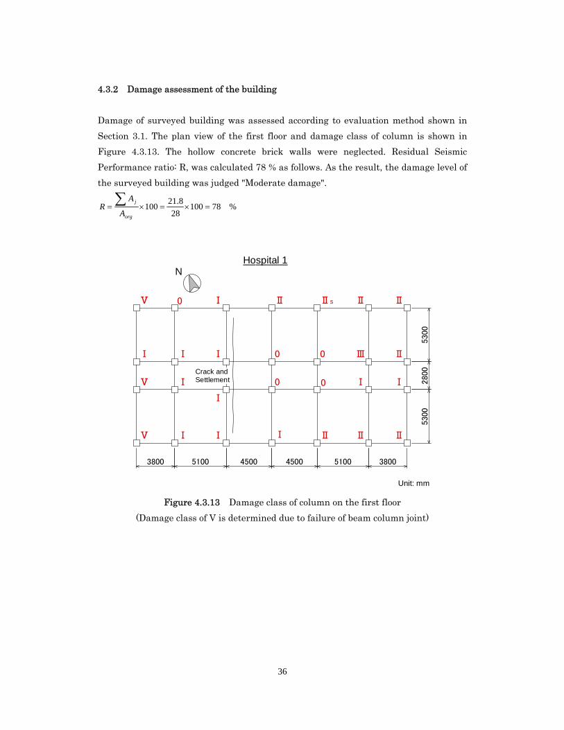
4.3.2 Damage assessment of the building
Damage of surveyed building was assessed according to evaluation method shown in
Section 3.1. The plan view of the first floor and damage class of column is shown in
Figure 4.3.13. The hollow concrete brick walls were neglected. Residual Seismic
Performance ratio: R, was calculated 78 % as follows. As the result, the damage level of
the surveyed building was judged "Moderate damage".
%7810028
8.21100
org
j
A
AR
Figure 4.3.13 Damage class of column on the first floor
(Damage class of V is determined due to failure of beam column joint)
NHospital 1
3800 5100 4500 4500 5100 3800
5300
2800
5300
Crack and Settlement
Ⅰ
Ⅰ Ⅰ
Ⅰ
Ⅰ Ⅰ
Ⅰ
Ⅰ
Ⅰ
Ⅰ
Ⅱ0
0
0
Ⅱ
0
0
Ⅱ
ⅡⅡs Ⅱ
Ⅱ
Ⅱ
Ⅰ
Ⅲ
Ⅴ
Ⅴ
Ⅴ
Unit: mm
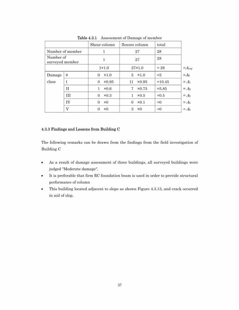
37
Table 4.3.1 Assessment of Damage of member
Shear column flexure column total
Number of member 1 27 28 Number of surveyed member 1 27 28
1×1.0 27×1.0 = 28 =Aorg
Damage
class
0 ×1.0 5 ×1.0 =5 =A0
0 ×0.95 11 ×0.95 =10.45 = A1
II 1 ×0.6 7 ×0.75 =5.85 = A2
III 0 ×0.3 1 ×0.5 =0.5 = A3
IV 0 ×0 0 ×0.1 =0 = A4
V 0 ×0 3 ×0 =0 = A5
4.3.3 Findings and Lessons from Building C
The following remarks can be drawn from the findings from the field investigation of
Building C
As a result of damage assessment of three buildings, all surveyed buildings were
judged "Moderate damage".
It is preferable that firm RC foundation beam is used in order to provide structural
performance of column
This building located adjacent to slope as shown Figure 4.3.13, and crack occurred
in soil of slop.
38
4.4 Building D: Hospital No. 2 (at Loon)
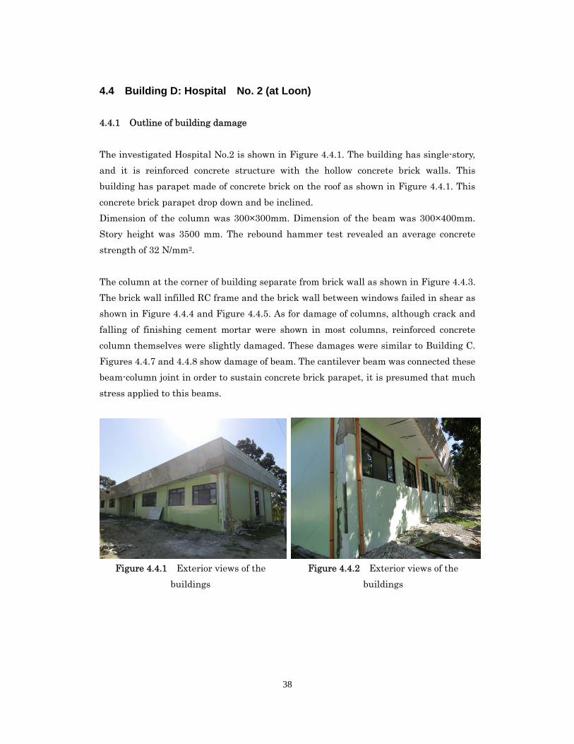
4.4.1 Outline of building damage
The investigated Hospital No.2 is shown in Figure 4.4.1. The building has single-story,
and it is reinforced concrete structure with the hollow concrete brick walls. This
building has parapet made of concrete brick on the roof as shown in Figure 4.4.1. This
concrete brick parapet drop down and be inclined.
Dimension of the column was 300×300mm. Dimension of the beam was 300×400mm.
Story height was 3500 mm. The rebound hammer test revealed an average concrete
strength of 32 N/mm2.
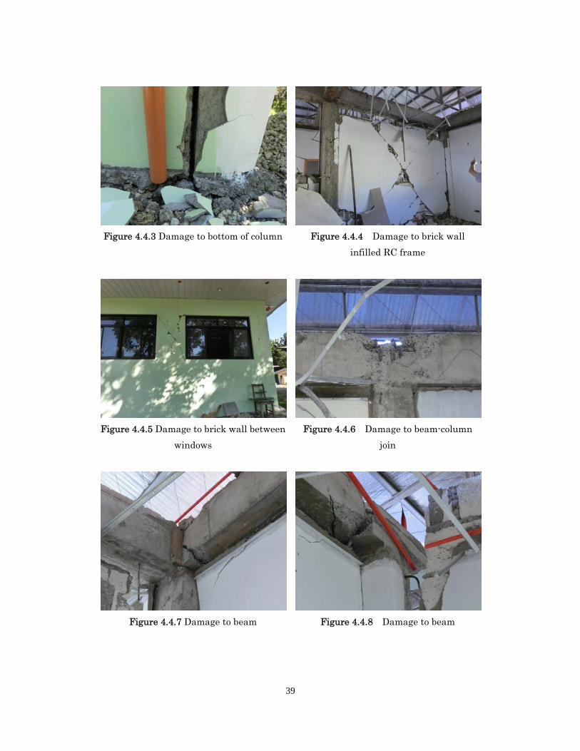
The column at the corner of building separate from brick wall as shown in Figure 4.4.3.
The brick wall infilled RC frame and the brick wall between windows failed in shear as
shown in Figure 4.4.4 and Figure 4.4.5. As for damage of columns, although crack and
falling of finishing cement mortar were shown in most columns, reinforced concrete
column themselves were slightly damaged. These damages were similar to Building C.
Figures 4.4.7 and 4.4.8 show damage of beam. The cantilever beam was connected these
beam-column joint in order to sustain concrete brick parapet, it is presumed that much
stress applied to this beams.
Figure 4.4.1 Exterior views of the
buildings
Figure 4.4.2 Exterior views of the
buildings
39
Figure 4.4.3 Damage to bottom of column Figure 4.4.4 Damage to brick wall
infilled RC frame
Figure 4.4.5 Damage to brick wall between
windows
Figure 4.4.6 Damage to beam-column
join
Figure 4.4.7 Damage to beam Figure 4.4.8 Damage to beam
40
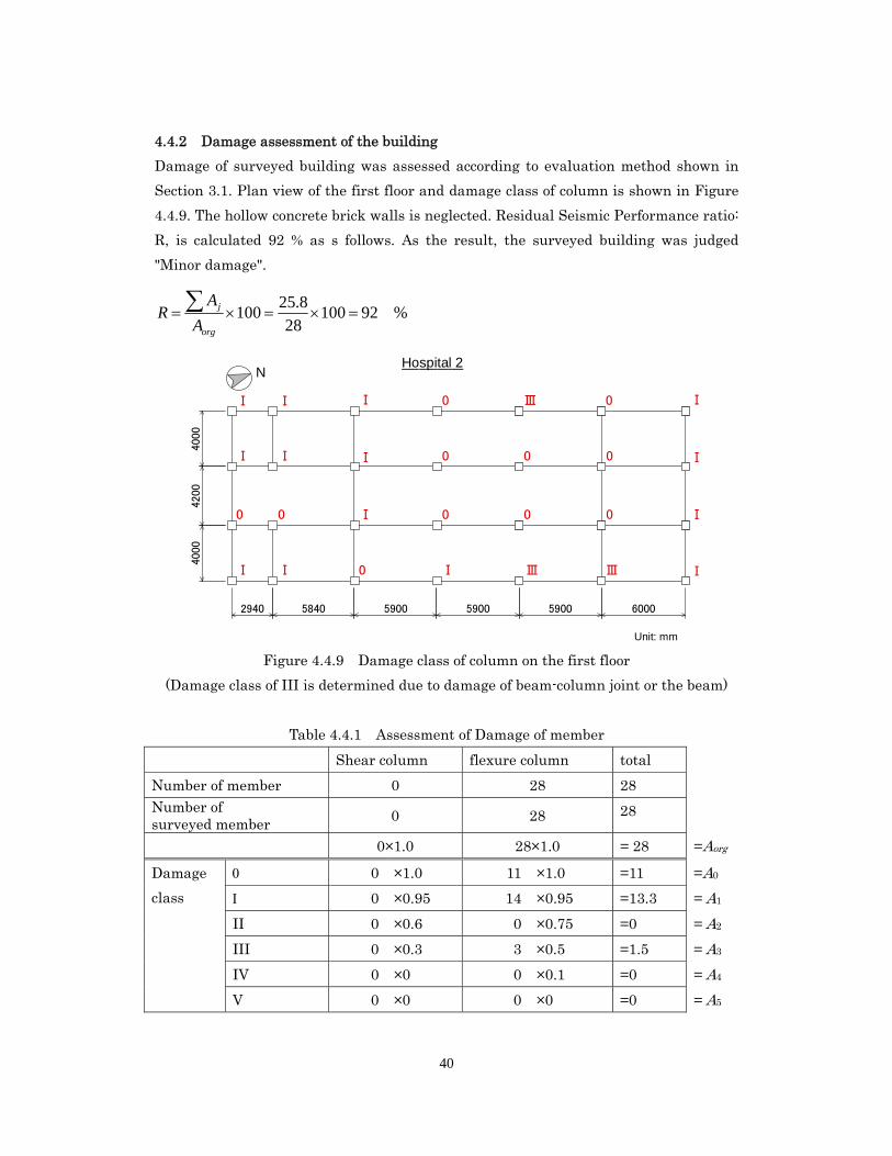
4.4.2 Damage assessment of the building
Damage of surveyed building was assessed according to evaluation method shown in
Section 3.1. Plan view of the first floor and damage class of column is shown in Figure
4.4.9. The hollow concrete brick walls is neglected. Residual Seismic Performance ratio:
R, is calculated 92 % as s follows. As the result, the surveyed building was judged
"Minor damage".
%9210028
8.25100
org
j
A
AR
Figure 4.4.9 Damage class of column on the first floor
(Damage class of III is determined due to damage of beam-column joint or the beam)
Table 4.4.1 Assessment of Damage of member
Shear column flexure column total
Number of member 0 28 28 Number of surveyed member 0 28 28
0×1.0 28×1.0 = 28 =Aorg
Damage
class
0 ×1.0 11 ×1.0 =11 =A0
0 ×0.95 14 ×0.95 =13.3 = A1
II 0 ×0.6 0 ×0.75 =0 = A2
III 0 ×0.3 3 ×0.5 =1.5 = A3
IV 0 ×0 0 ×0.1 =0 = A4
V 0 ×0 0 ×0 =0 = A5
NHospital 2
2940 5840 5900 5900 5900 6000
4000
4200
400
0
Ⅰ
0
Ⅰ
Ⅰ
Ⅰ
Ⅰ
Ⅰ
0
0
Ⅰ
Ⅰ
Ⅰ
0
0
0
0
0
0
0
0
Ⅰ
Ⅰ
Ⅰ
Ⅰ
Unit: mm
Ⅲ
ⅢⅠ Ⅲ
41
4.4.3 Findings and Lessons from Building D
The following remarks can be drawn from the findings from the field investigation of
Building D
As a result of damage assessment of three buildings, all surveyed buildings were
judged "Moderate damage".
This building has parapet made of concrete brick on the roof. The cantilever beam
was connected these beam-column joint in order to sustain concrete brick parapet,
it is presumed that much stress applied to this beams.
42
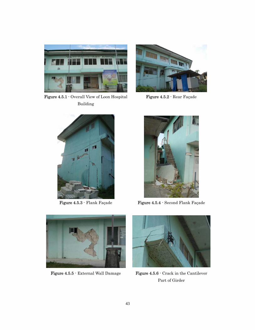
4.5 Building E: Hospital No. 3 (at Loon)
4.5.1 Outline of building damage
The Loon Hospital is a two-storey building located in the municipality of Loon, in the
central part of the Bohol island, at some distance from the earthquake epicenter.
The building has a complex configuration with the overall dimensions 25.0х8.0 m in the
plan. It is a two-storey building, the storey height being 3.2 and 3.0 m. The structural
design is a reinforced concrete frame consisting of columns and two-way beams. The
columns of the first floor have rectangular cross-section of 300х500 mm. The columns
grid is 3.0х8.0 m. The columns of the second floor have the section of 300х350 mm.
The floor structure consists of the two-way reinforced concrete beams and cast
reinforced concrete floor slab. The covering structure consists of the timber triangular
truss. The roof coating has four sloping surfaces and is covered by the metal fluted
sheets. The walls are made of hollow concrete blocks (the material is porous concrete)
with subsequent filling of cavities with the reinforced concrete. There is a staircase,
which is made of the wooden structures.
Overview of damage
Primary structure: there are cracks in the separate external and internal walls. The
general condition of the bearing structures is estimated as satisfactory.
Secondary structure: the internal wall of the first floor is blocked near the staircase; the
wall is ruined on the second floor. There is a crack seen in the cantilever part of the rear
façade girder. The condition of the separate filler structures is estimated as
unsatisfactory.
43
Figure 4.5.1 - Overall View of Loon Hospital
Building
Figure 4.5.3 - Flank Façade
Figure 4.5.5 - External Wall Damage
Figure 4.5.2 - Rear Façade
Figure 4.5.4 - Second Flank Façade
Figure 4.5.6 - Crack in the Cantilever
Part of Girder
44
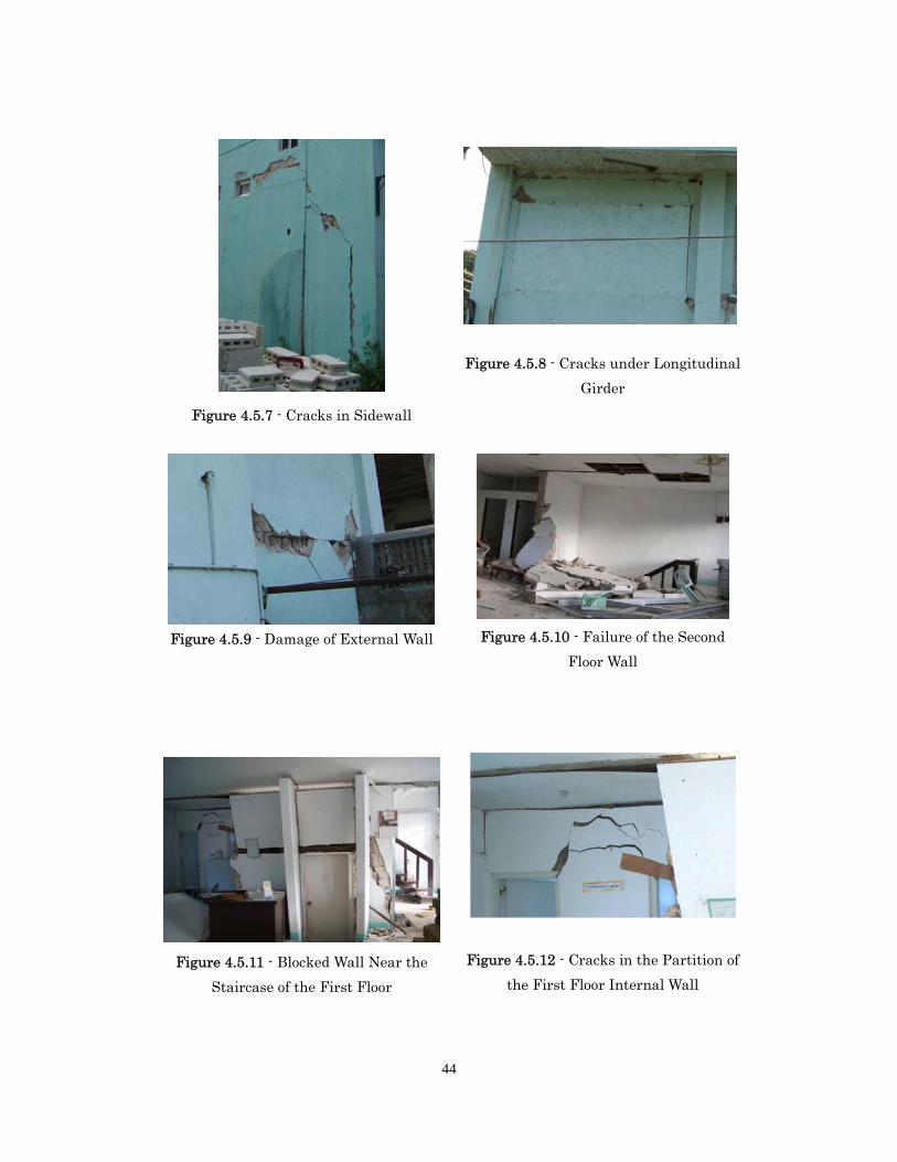
Figure 4.5.7 - Cracks in Sidewall
Figure 4.5.9 - Damage of External Wall
Figure 4.5.11 - Blocked Wall Near the
Staircase of the First Floor
Figure 4.5.8 - Cracks under Longitudinal
Girder
Figure 4.5.10 - Failure of the Second
Floor Wall
Figure 4.5.12 - Cracks in the Partition of
the First Floor Internal Wall
45
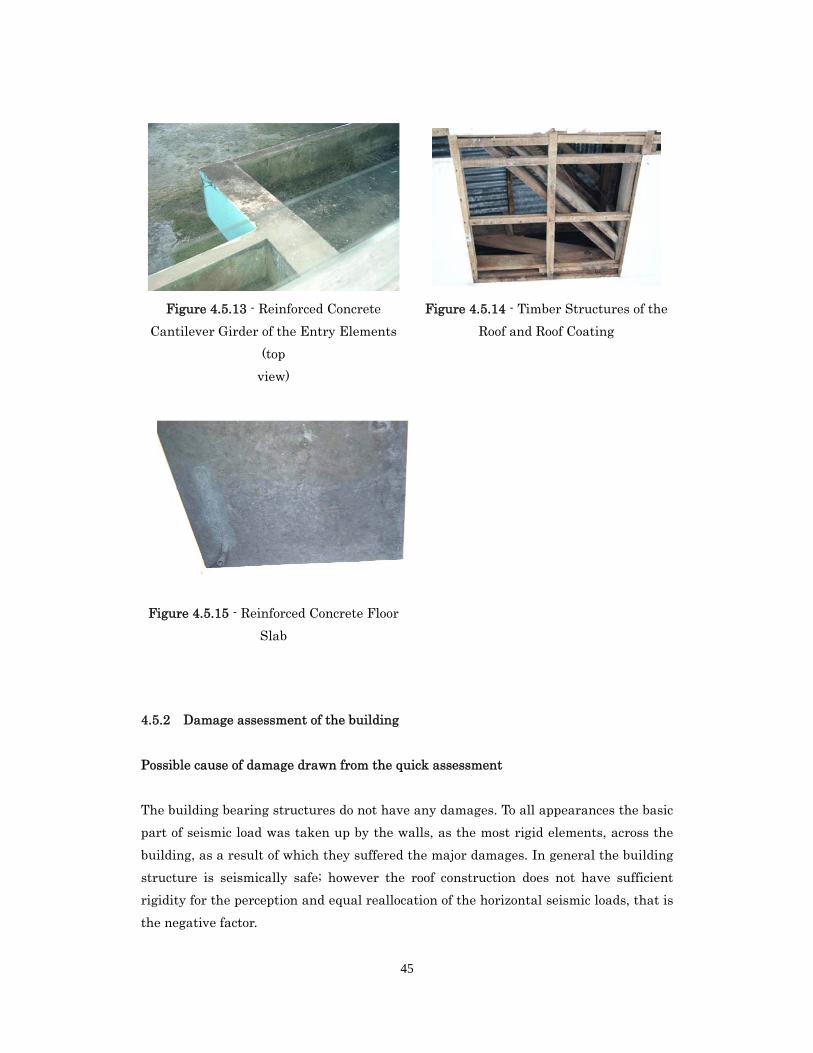
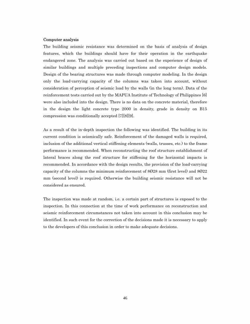
Figure 4.5.13 - Reinforced Concrete
Cantilever Girder of the Entry Elements
(top
view)
Figure 4.5.15 - Reinforced Concrete Floor
Slab
Figure 4.5.14 - Timber Structures of the
Roof and Roof Coating
4.5.2 Damage assessment of the building
Possible cause of damage drawn from the quick assessment
The building bearing structures do not have any damages. To all appearances the basic
part of seismic load was taken up by the walls, as the most rigid elements, across the
building, as a result of which they suffered the major damages. In general the building
structure is seismically safe; however the roof construction does not have sufficient
rigidity for the perception and equal reallocation of the horizontal seismic loads, that is
the negative factor.
46
Computer analysis
The building seismic resistance was determined on the basis of analysis of design
features, which the buildings should have for their operation in the earthquake
endangered zone. The analysis was carried out based on the experience of design of
similar buildings and multiple preceding inspections and computer design models.
Design of the bearing structures was made through computer modeling. In the design
only the load-carrying capacity of the columns was taken into account, without
consideration of perception of seismic load by the walls (in the long term). Data of the
reinforcement tests carried out by the MAPUA Institute of Technology of Philippines [6]
were also included into the design. There is no data on the concrete material, therefore
in the design the light concrete type 2000 in density, grade in density on B15
compression was conditionally accepted [7][8][9].
As a result of the in-depth inspection the following was identified. The building in its
current condition is seismically safe. Reinforcement of the damaged walls is required,
inclusion of the additional vertical stiffening elements (walls, trusses, etc.) to the frame
performance is recommended. When reconstructing the roof structure establishment of
lateral braces along the roof structure for stiffening for the horizontal impacts is
recommended. In accordance with the design results, the provision of the load-carrying
capacity of the columns the minimum reinforcement of 8Ø28 mm (first level) and 8Ø22
mm (second level) is required. Otherwise the building seismic resistance will not be
considered as ensured.
The inspection was made at random, i.e. a certain part of structures is exposed to the
inspection. In this connection at the time of work performance on reconstruction and
seismic reinforcement circumstances not taken into account in this conclusion may be
identified. In such event for the correction of the decisions made it is necessary to apply
to the developers of this conclusion in order to make adequate decisions.
47
4.5.3 Findings and Lessons from Building E
The following remarks can be drawn from the findings from the field investigation of
Building E
In general the building structure is seismically safe.
The roof construction does not have sufficient rigidity for the perception and equal
reallocation of the horizontal seismic loads.
Reinforcement of the damaged walls is required, inclusion of the additional vertical
stiffening elements (walls, trusses, etc.).
When reconstructing the roof structure establishment of lateral braces along the
roof structure for stiffening for the horizontal impacts is recommended
48
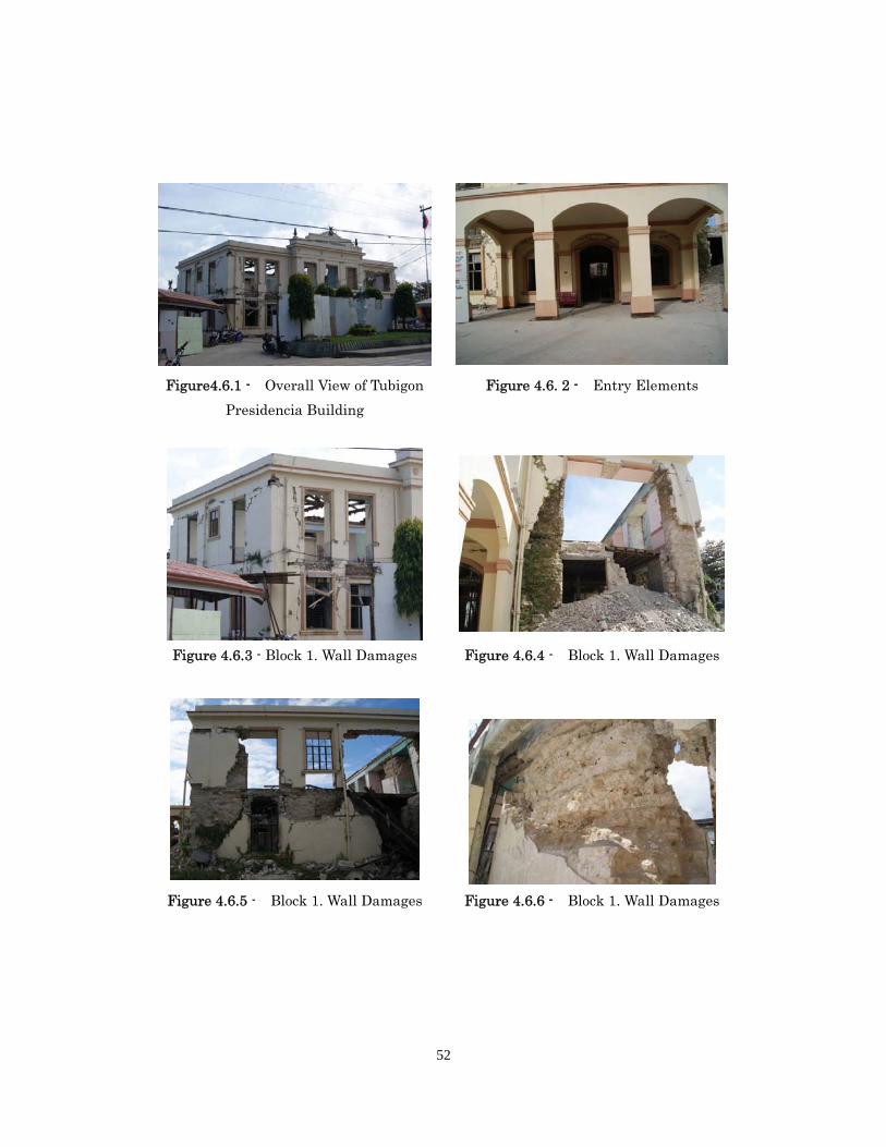
4.6 Building F: Governmental Building (at Tobigron)
4.6.1 Outline of building damage
The building inspected is located in the territory of Bohol Island (Philippines).
The Tubigon Presidencia building is located in the municipality of Tubigon situated in
the north-western coastal part of the island, which is close to the epicentral area.
Function – administrative building. Age not established.
The Tubigon Presidencia building has a configuration complex in its plan and consists of
4 blocks. There is a public building adjacent to the main building, which has no
functional relation to the inspected part and is separated from it with a seismic joint
about 1 meter wide, therefore it was not included into the inspection goal. There is no
project documentation for the building.
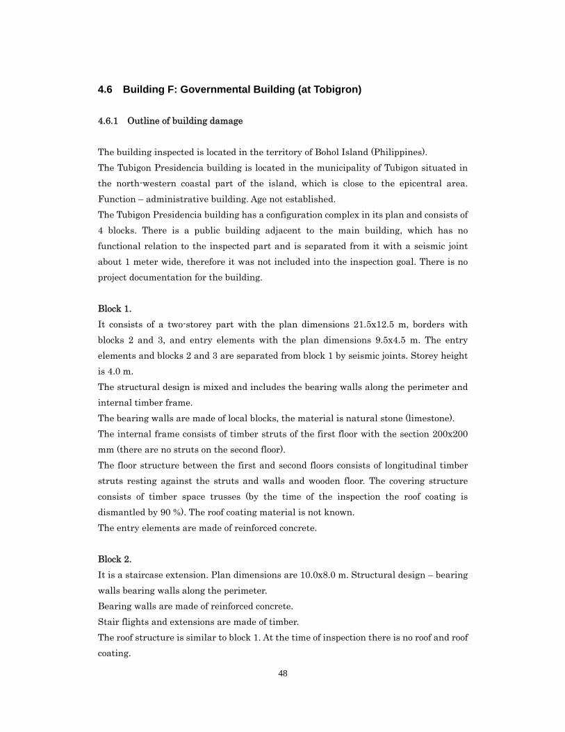
Block 1.
It consists of a two-storey part with the plan dimensions 21.5х12.5 m, borders with
blocks 2 and 3, and entry elements with the plan dimensions 9.5х4.5 m. The entry
elements and blocks 2 and 3 are separated from block 1 by seismic joints. Storey height
is 4.0 m.
The structural design is mixed and includes the bearing walls along the perimeter and
internal timber frame.
The bearing walls are made of local blocks, the material is natural stone (limestone).
The internal frame consists of timber struts of the first floor with the section 200х200
mm (there are no struts on the second floor).
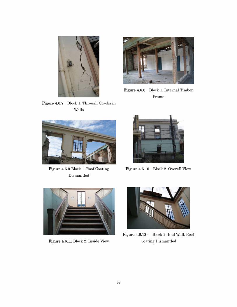
The floor structure between the first and second floors consists of longitudinal timber
struts resting against the struts and walls and wooden floor. The covering structure
consists of timber space trusses (by the time of the inspection the roof coating is
dismantled by 90 %). The roof coating material is not known.
The entry elements are made of reinforced concrete.
Block 2.
It is a staircase extension. Plan dimensions are 10.0х8.0 m. Structural design – bearing
walls bearing walls along the perimeter.
Bearing walls are made of reinforced concrete.
Stair flights and extensions are made of timber.
The roof structure is similar to block 1. At the time of inspection there is no roof and roof
coating.
49
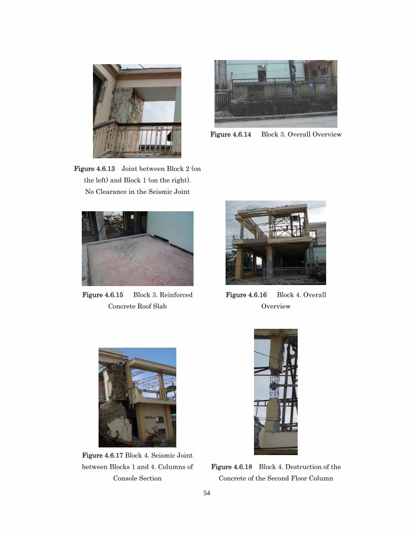
Block 3.
It is a basement single-level structure. Plan dimensions are 8.0х3.5 m, height is 2.5 m.
It is adjacent to block 2, there are no seismic joints. Structural design is bearing walls
along the perimeter.
Bearing walls are made of reinforced concrete.
The roof structure is a cast reinforced concrete slab.
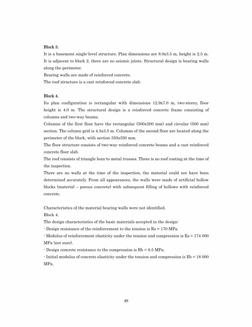
Block 4.
Its plan configuration is rectangular with dimensions 12.9х7.0 m, two-storey, floor
height is 4.0 m. The structural design is a reinforced concrete frame consisting of
columns and two-way beams.
Columns of the first floor have the rectangular (500х500 mm) and circular (500 mm)
section. The column grid is 4.3х3.5 m. Columns of the second floor are located along the
perimeter of the block, with section 350х350 mm.
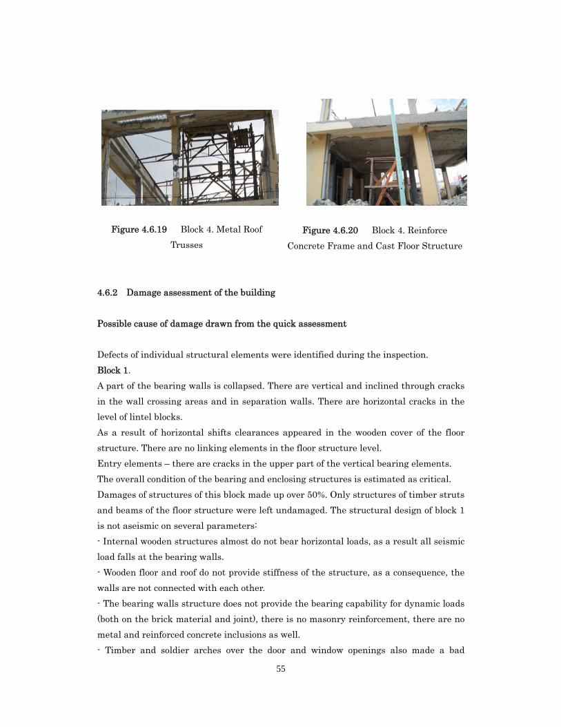
The floor structure consists of two-way reinforced concrete beams and a cast reinforced
concrete floor slab.
The roof consists of triangle lean-to metal trusses. There is no roof coating at the time of
the inspection.
There are no walls at the time of the inspection, the material could not have been
determined accurately. From all appearances, the walls were made of artificial hollow
blocks (material – porous concrete) with subsequent filling of hollows with reinforced
concrete.
Characteristics of the material bearing walls were not identified.
Block 4.
The design characteristics of the basic materials accepted in the design:
- Design resistance of the reinforcement to the tension is Rs = 170 MPa.
- Modulus of reinforcement elasticity under the tension and compression is Es = 174 000
MPa (not sure).
- Design concrete resistance to the compression is Rb = 8.5 MPa.
- Initial modulus of concrete elasticity under the tension and compression is Eb = 18 000
MPa.
50
51
52
Figure4.6.1 - Overall View of Tubigon
Presidencia Building
Figure 4.6.3 - Block 1. Wall Damages
Figure 4.6.5 - Block 1. Wall Damages
Figure 4.6. 2 - Entry Elements
Figure 4.6.4 - Block 1. Wall Damages
Figure 4.6.6 - Block 1. Wall Damages
53
Figure 4.6.7 Block 1. Through Cracks in
Walls
Figure 4.6.9 Block 1. Roof Coating
Dismantled
Figure 4.6.11 Block 2. Inside View
Figure 4.6.8 Block 1. Internal Timber
Frame
Figure 4.6.10 Block 2. Overall View
Figure 4.6.12 - Block 2. End Wall. Roof
Coating Dismantled
54
Figure 4.6.13 Joint between Block 2 (on
the left) and Block 1 (on the right).
No Clearance in the Seismic Joint
Figure 4.6.15 Block 3. Reinforced
Concrete Roof Slab
Figure 4.6.17 Block 4. Seismic Joint
between Blocks 1 and 4. Columns of
Console Section
Figure 4.6.14 Block 3. Overall Overview
Figure 4.6.16 Block 4. Overall
Overview
Figure 4.6.18 Block 4. Destruction of the
Concrete of the Second Floor Column
55
Figure 4.6.19 Block 4. Metal Roof
Trusses
Figure 4.6.20 Block 4. Reinforce
Concrete Frame and Cast Floor Structure
4.6.2 Damage assessment of the building
Possible cause of damage drawn from the quick assessment
Defects of individual structural elements were identified during the inspection.
Block 1.
A part of the bearing walls is collapsed. There are vertical and inclined through cracks
in the wall crossing areas and in separation walls. There are horizontal cracks in the
level of lintel blocks.
As a result of horizontal shifts clearances appeared in the wooden cover of the floor
structure. There are no linking elements in the floor structure level.
Entry elements – there are cracks in the upper part of the vertical bearing elements.
The overall condition of the bearing and enclosing structures is estimated as critical.
Damages of structures of this block made up over 50%. Only structures of timber struts
and beams of the floor structure were left undamaged. The structural design of block 1
is not aseismic on several parameters:
- Internal wooden structures almost do not bear horizontal loads, as a result all seismic
load falls at the bearing walls.
- Wooden floor and roof do not provide stiffness of the structure, as a consequence, the
walls are not connected with each other.
- The bearing walls structure does not provide the bearing capability for dynamic loads
(both on the brick material and joint), there is no masonry reinforcement, there are no
metal and reinforced concrete inclusions as well.
- Timber and soldier arches over the door and window openings also made a bad
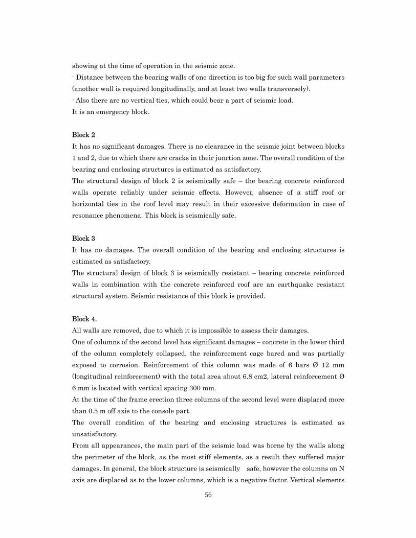
56
showing at the time of operation in the seismic zone.
- Distance between the bearing walls of one direction is too big for such wall parameters
(another wall is required longitudinally, and at least two walls transversely).
- Also there are no vertical ties, which could bear a part of seismic load.
It is an emergency block.
Block 2
It has no significant damages. There is no clearance in the seismic joint between blocks
1 and 2, due to which there are cracks in their junction zone. The overall condition of the
bearing and enclosing structures is estimated as satisfactory.
The structural design of block 2 is seismically safe – the bearing concrete reinforced
walls operate reliably under seismic effects. However, absence of a stiff roof or
horizontal ties in the roof level may result in their excessive deformation in case of
resonance phenomena. This block is seismically safe.
Block 3
It has no damages. The overall condition of the bearing and enclosing structures is
estimated as satisfactory.
The structural design of block 3 is seismically resistant – bearing concrete reinforced
walls in combination with the concrete reinforced roof are an earthquake resistant
structural system. Seismic resistance of this block is provided.
Block 4.
All walls are removed, due to which it is impossible to assess their damages.
One of columns of the second level has significant damages – concrete in the lower third
of the column completely collapsed, the reinforcement cage bared and was partially
exposed to corrosion. Reinforcement of this column was made of 6 bars Ø 12 mm
(longitudinal reinforcement) with the total area about 6.8 cm2, lateral reinforcement Ø
6 mm is located with vertical spacing 300 mm.
At the time of the frame erection three columns of the second level were displaced more
than 0.5 m off axis to the console part.
The overall condition of the bearing and enclosing structures is estimated as
unsatisfactory.
From all appearances, the main part of the seismic load was borne by the walls along
the perimeter of the block, as the most stiff elements, as a result they suffered major
damages. In general, the block structure is seismically safe, however the columns on N
axis are displaced as to the lower columns, which is a negative factor. Vertical elements
57
should be located directly one over another, with no shifts.
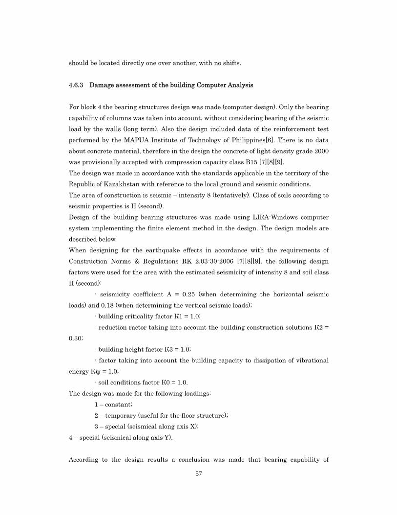
4.6.3 Damage assessment of the building Computer Analysis
For block 4 the bearing structures design was made (computer design). Only the bearing
capability of columns was taken into account, without considering bearing of the seismic
load by the walls (long term). Also the design included data of the reinforcement test
performed by the MAPUA Institute of Technology of Philippines[6]. There is no data
about concrete material, therefore in the design the concrete of light density grade 2000
was provisionally accepted with compression capacity class В15 [7][8][9].
The design was made in accordance with the standards applicable in the territory of the
Republic of Kazakhstan with reference to the local ground and seismic conditions.
The area of construction is seismic – intensity 8 (tentatively). Class of soils according to
seismic properties is II (second).
Design of the building bearing structures was made using LIRA-Windows computer
system implementing the finite element method in the design. The design models are
described below.
When designing for the earthquake effects in accordance with the requirements of
Construction Norms & Regulations RK 2.03-30-2006 [7][8][9]. the following design
factors were used for the area with the estimated seismicity of intensity 8 and soil class
II (second):
- seismicity coefficient А = 0.25 (when determining the horizontal seismic
loads) and 0.18 (when determining the vertical seismic loads);
- building criticality factor К1 = 1.0;
- reduction ractor taking into account the building construction solutions К2 =
0.30;
- building height factor К3 = 1.0;
- factor taking into account the building capacity to dissipation of vibrational
energy Кψ = 1.0;
- soil conditions factor К0 = 1.0.
The design was made for the following loadings:
1 – constant;
2 – temporary (useful for the floor structure);
3 – special (seismical along axis X);
4 – special (seismical along axis Y).
According to the design results a conclusion was made that bearing capability of
58
columns does not provide seismic resistance of the block, reinforcement of the damaged
column is not enough, 8Ø28 mm (first level) and 8Ø22 mm (second level). It is necessary
either to reinforce them or include additional vertical stiffness elements into the work
(walls, ties, etc.). In the current state this block is earthquake-prone.
4.6.4 Findings and Lessons from Building F
The following remarks can be drawn from the findings from the field investigation of
Building F
Block 1, a part of the bearing walls is collapsed Block 2 and 3 don’t have significant
damage. Block 4, All walls are removed, due to which it is impossible to assess their
damages
There is no clearance in the seismic joint between blocks 1 and 2, due to which
there are cracks in their junction zone.
The columns on N axis are displaced as to the lower columns, which is a negative
factor. Vertical elements should be located directly one over another, with no shifts..
Bearing capability of columns does not provide seismic resistance of the block,
reinforcement of the damaged column is not enough
59
5. Conclusion for RC buildings
All findings of 6 buildings that were conducted detailed assessment are listed below
again.
Building A
It is presumed that strength of concrete brick was small since the quality of the
bricks was not good.
Since some columns do not have girders in one direction, the lateral strength could
be reduced, which may reduce the base shear coefficient.
Most of columns of dimensions 270 × 270 mm failed in shear.
Building B
Since some columns do not have girders in one direction, the lateral strength could
be reduced, which may reduce the base shear coefficient.
From pushover computer analysis, story drift at the first story is considerably
larger than that at the second story, and it is found that plastic hinge develop end of
column in first story. These results are corresponding to story collapse at the first
story of damaged building.
Building C
It is preferable that firm RC foundation beam is used in order to provide structural
performance of column
This building located adjacent to slope, and crack occurred in soil of slop.
Building D
This building has parapet made of concrete brick on the roof. The cantilever beam
was connected these beam-column joint in order to sustain concrete brick parapet,
it is presumed that much stress applied to this beams.
Building E
The roof construction does not have sufficient rigidity for the perception and equal
reallocation of the horizontal seismic loads.
Reinforcement of the damaged walls is required, inclusion of the additional vertical
stiffening elements (walls, trusses, etc.).
When reconstructing the roof structure establishment of lateral braces along the
roof structure for stiffening for the horizontal impacts is recommended
60
Building F
There is no clearance in the seismic joint between blocks 1 and 2, due to which
there are cracks in their junction zone.
The columns on N axis are displaced as to the lower columns, which is a negative
factor. Vertical elements should be located directly one over another, with no shifts.
Bearing capability of columns does not provide seismic resistance of the block,
reinforcement of the damaged column is not enough
Recommendation
Taking into account that these 6 buildings don’t necessarily represent all buildings in
Bohol or Philippines, however, we could draw recommendations from perspective of 1)
Structural Design, 2) Material and 3) Zoning from our investigation.
Structural Elements
Foundation:
Building without RC foundation beam, that caused the reduction of structural
performance of columns was observed. In order to secure enough strength for shear
force, it is recommended that have RC foundation beam and columns/bearing walls are
rigidly connected (Ex: reviewing structural/seismic code/standard, reviewing building
control system (interim check etc.)).
Columns:
Failure in shear in small dimension columns was observed. Also the displacement of
columns on N axis was observed. These are assumed to be caused due to lack of
principle in the building code or inappropriate practice during construction. It is
recommended that the columns have enough dimension size to sustain the earthquake
force and columns are vertically placed appropriately. (Ex: Reviewing the building
code/standard for the structural/seismic safety principle and reviewing the building
control (interim check). Reviewing seismic design force or safety factor in the structural
design)
Columns and Walls:
Crash of first floor in piloti building was observed. The crash was caused by plastic
hinge in the columns of first floor. It is recommended to have enough columns and walls
to sustain earthquake force (Ex: reviewing structural/seismic design for enough
columns and walls and balance of planning in order to avoid crash/swing of the
building).
Beam:
61
Lack of connection between beam and columns was observed. These are assumed to be
caused due to lack of principle in the building code or inappropriate practice during
construction. (Ex: Reviewing the building code/standard for the structural/seismic
safety principle and reviewing the building control (interim check). Reviewing seismic
design force or safety factor in the structural design).
Roof:
Lack of rigidity in the roof structure was observed, that caused the unequal reallocation
of the horizontal seismic loads. These are assumed to be caused due to lack of principle
in the building code or inappropriate practice during construction. (Ex: Reviewing the
building code/standard for the structural/seismic safety principle and reviewing the
building control (interim check). Reviewing seismic design force or safety factor in the
structural design).
Design:
Unbalanced design with top heavy concrete parapet that caused the damage on parapet
and beams was observed. Also, the lack of clearance between two different structures
that caused the cracks in the junction zone was observed. (Ex: Reviewing the building
code/standard for the structural/seismic safety principle and reviewing seismic design
force or safety factor in the structural design).
Material
Crash of concrete block and the exposure of mortar in the block’s hollow were observed.
This is the lack of strength of the block. It is recommended that the material is secured
to have enough strength to sustain earthquake force. (Ex: reviewing material standards
and quality control of material).
Zoning
Cracks in buildings adjacent to slope were observed. It is recommended that the
buildings are built based on the risk the location have. (Ex: reviewing the zoning code
site selection and design of foundation in building code).
62
6. Condition Assessment of Four Heritage Churches on the Island of Bohol
6.1 Church of Our Lady of the Immaculate Conception in Baclayon
Background and Description
The Church of Our Lady of the Immaculate Conception (Figure 6.1.1) is located in
Baclayon (9˚ 37’ 22” north; 123˚ 54’ 44’ east; elevation 22 metres). Founded in 1595, it is
one of the oldest churches in the Philippines and the present structure is one of the best
preserved Jesuit-built churches in the region. Construction of the present structure was
begun after 1717 and completed in 1727. The bell tower was completed in 1777. In the
19th century, a new façade with portico was added, along with a number of stone
buildings that now surround the church. Next to the church is the convento. A new wing
was added to the convento in 1872. The convento is now the Baclayon Museum.
The Church of Our Lady of the Immaculate Conception is cruciform in plan with an
octagonal dome at the crossing, an octagonal baptistry off of the west transept, and a
convento connected to the east transept (see drawings in Appendix A). The bell tower is
square in plan and is located in front of, and to the east of, the main entrance. The
exterior masonry bearing walls are composed of dressed coral stone exterior and interior
surfaces.
There are buttresses on the longitudinal walls with two levels of windows between each
buttress. The roof structure is a wood A-frame truss with 150x250 mm (6x10 inch) top
chords and a 100x200 mm (4x8 inch) horizontal center brace. There are four trusses
per bay. At each bay of the nave the walls are tied together with a horizontal wooden
250x350 mm (10x14 inch) beam. These beams also engage the base of the
aforementioned trusses.
The roofing is painted corrugated metal that simulates the appearance of Spanish tiles.
The interior walls are finished with dressed coral stone and the ceiling is
monochromatic fabric stretched over board planking. The altar ceiling is polychromed.
The floors are cement tile over a concrete slab on grade.
The church is oriented with its entrance to the south and altar to the north. It is south
southwest of the epicenter of the earthquake.
63
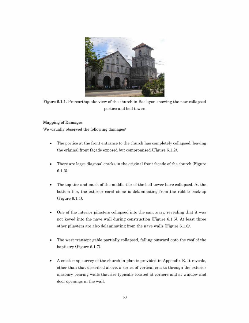
Figure 6.1.1. Pre-earthquake view of the church in Baclayon showing the now collapsed
portico and bell tower.
Mapping of Damages
We visually observed the following damages:
The portico at the front entrance to the church has completely collapsed, leaving
the original front façade exposed but compromised (Figure 6.1.2).
There are large diagonal cracks in the original front façade of the church (Figure
6.1.3).
The top tier and much of the middle tier of the bell tower have collapsed. At the
bottom tier, the exterior coral stone is delaminating from the rubble back-up
(Figure 6.1.4).
One of the interior pilasters collapsed into the sanctuary, revealing that it was
not keyed into the nave wall during construction (Figure 6.1.5). At least three
other pilasters are also delaminating from the nave walls (Figure 6.1.6).
The west transept gable partially collapsed, falling outward onto the roof of the
baptistry (Figure 6.1.7).
A crack map survey of the church in plan is provided in Appendix E. It reveals,
other than that described above, a series of vertical cracks through the exterior
masonry bearing walls that are typically located at corners and at window and
door openings in the wall.
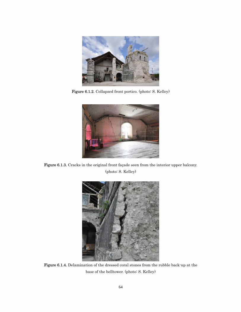
64
Figure 6.1.2. Collapsed front portico. (photo: S. Kelley)
Figure 6.1.3. Cracks in the original front façade seen from the interior upper balcony.
(photo: S. Kelley)
Figure 6.1.4. Delamination of the dressed coral stones from the rubble back-up at the
base of the belltower. (photo: S. Kelley)
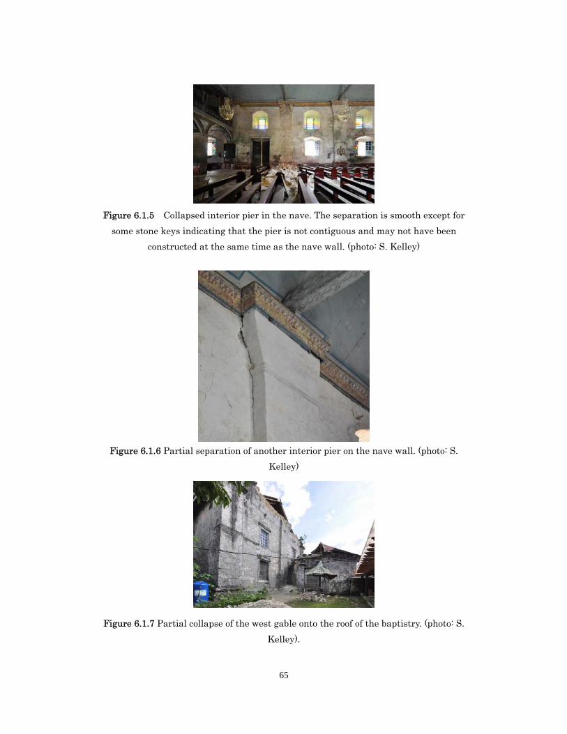
65
Figure 6.1.5 Collapsed interior pier in the nave. The separation is smooth except for
some stone keys indicating that the pier is not contiguous and may not have been
constructed at the same time as the nave wall. (photo: S. Kelley)
Figure 6.1.6 Partial separation of another interior pier on the nave wall. (photo: S.
Kelley)
Figure 6.1.7 Partial collapse of the west gable onto the roof of the baptistry. (photo: S.
Kelley).
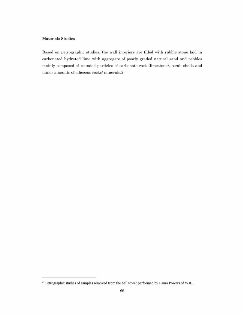
66
Materials Studies
Based on petrographic studies, the wall interiors are filled with rubble stone laid in
carbonated hydrated lime with aggregate of poorly graded natural sand and pebbles
mainly composed of rounded particles of carbonate rock (limestone), coral, shells and
minor amounts of siliceous rocks/ minerals.2
2 Petrographic studies of samples removed from the bell tower performed by Laura Powers of WJE.
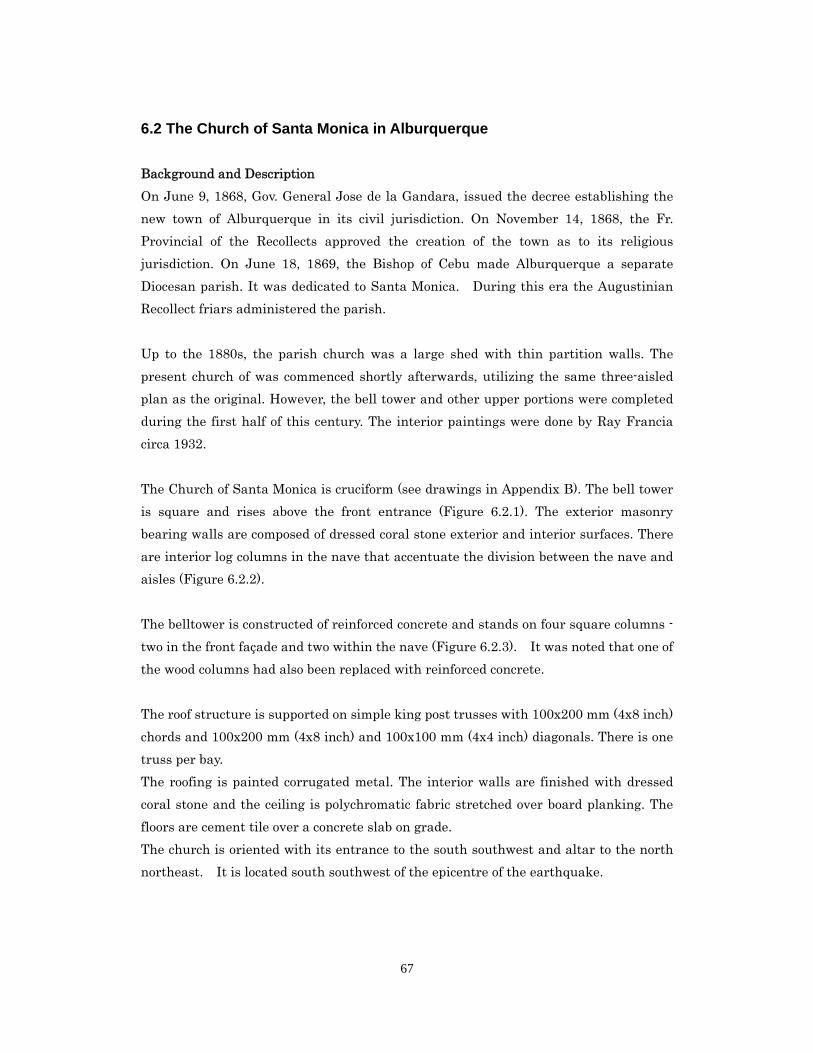
67
6.2 The Church of Santa Monica in Alburquerque
Background and Description
On June 9, 1868, Gov. General Jose de la Gandara, issued the decree establishing the
new town of Alburquerque in its civil jurisdiction. On November 14, 1868, the Fr.
Provincial of the Recollects approved the creation of the town as to its religious
jurisdiction. On June 18, 1869, the Bishop of Cebu made Alburquerque a separate
Diocesan parish. It was dedicated to Santa Monica. During this era the Augustinian
Recollect friars administered the parish.
Up to the 1880s, the parish church was a large shed with thin partition walls. The
present church of was commenced shortly afterwards, utilizing the same three-aisled
plan as the original. However, the bell tower and other upper portions were completed
during the first half of this century. The interior paintings were done by Ray Francia
circa 1932.
The Church of Santa Monica is cruciform (see drawings in Appendix B). The bell tower
is square and rises above the front entrance (Figure 6.2.1). The exterior masonry
bearing walls are composed of dressed coral stone exterior and interior surfaces. There
are interior log columns in the nave that accentuate the division between the nave and
aisles (Figure 6.2.2).
The belltower is constructed of reinforced concrete and stands on four square columns -
two in the front façade and two within the nave (Figure 6.2.3). It was noted that one of
the wood columns had also been replaced with reinforced concrete.
The roof structure is supported on simple king post trusses with 100x200 mm (4x8 inch)
chords and 100x200 mm (4x8 inch) and 100x100 mm (4x4 inch) diagonals. There is one
truss per bay.
The roofing is painted corrugated metal. The interior walls are finished with dressed
coral stone and the ceiling is polychromatic fabric stretched over board planking. The
floors are cement tile over a concrete slab on grade.
The church is oriented with its entrance to the south southwest and altar to the north
northeast. It is located south southwest of the epicentre of the earthquake.
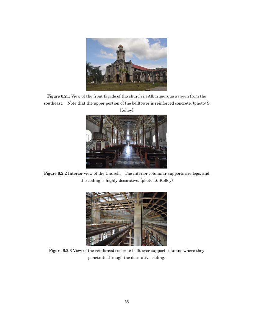
68
Figure 6.2.1 View of the front façade of the church in Alburquerque as seen from the
southeast. Note that the upper portion of the belltower is reinforced concrete. (photo: S.
Kelley)
Figure 6.2.2 Interior view of the Church. The interior columnar supports are logs, and
the ceiling is highly decorative. (photo: S. Kelley)
Figure 6.2.3 View of the reinforced concrete belltower support columns where they
penetrate through the decorative ceiling.
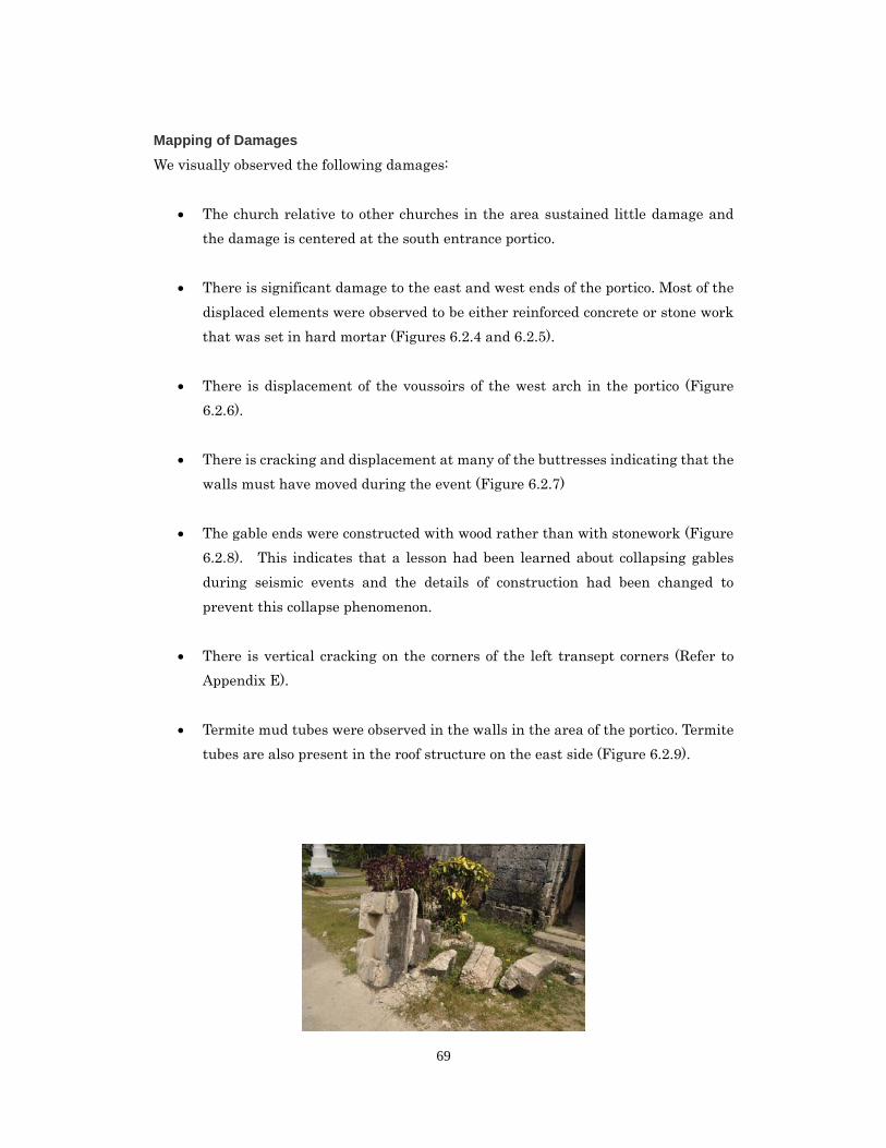
69
Mapping of Damages
We visually observed the following damages:
The church relative to other churches in the area sustained little damage and
the damage is centered at the south entrance portico.
There is significant damage to the east and west ends of the portico. Most of the
displaced elements were observed to be either reinforced concrete or stone work
that was set in hard mortar (Figures 6.2.4 and 6.2.5).
There is displacement of the voussoirs of the west arch in the portico (Figure
6.2.6).
There is cracking and displacement at many of the buttresses indicating that the
walls must have moved during the event (Figure 6.2.7)
The gable ends were constructed with wood rather than with stonework (Figure
6.2.8). This indicates that a lesson had been learned about collapsing gables
during seismic events and the details of construction had been changed to
prevent this collapse phenomenon.
There is vertical cracking on the corners of the left transept corners (Refer to
Appendix E).
Termite mud tubes were observed in the walls in the area of the portico. Termite
tubes are also present in the roof structure on the east side (Figure 6.2.9).
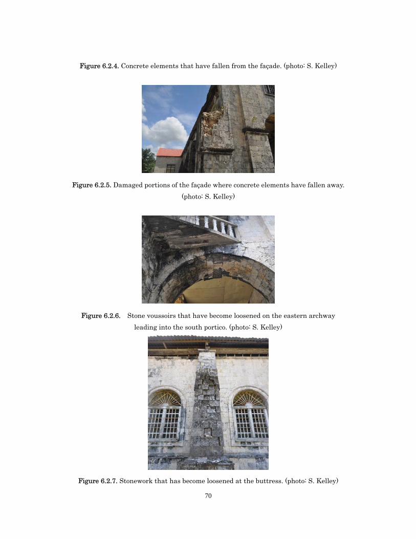
70
Figure 6.2.4. Concrete elements that have fallen from the façade. (photo: S. Kelley)
Figure 6.2.5. Damaged portions of the façade where concrete elements have fallen away.
(photo: S. Kelley)
Figure 6.2.6. Stone voussoirs that have become loosened on the eastern archway
leading into the south portico. (photo: S. Kelley)
Figure 6.2.7. Stonework that has become loosened at the buttress. (photo: S. Kelley)
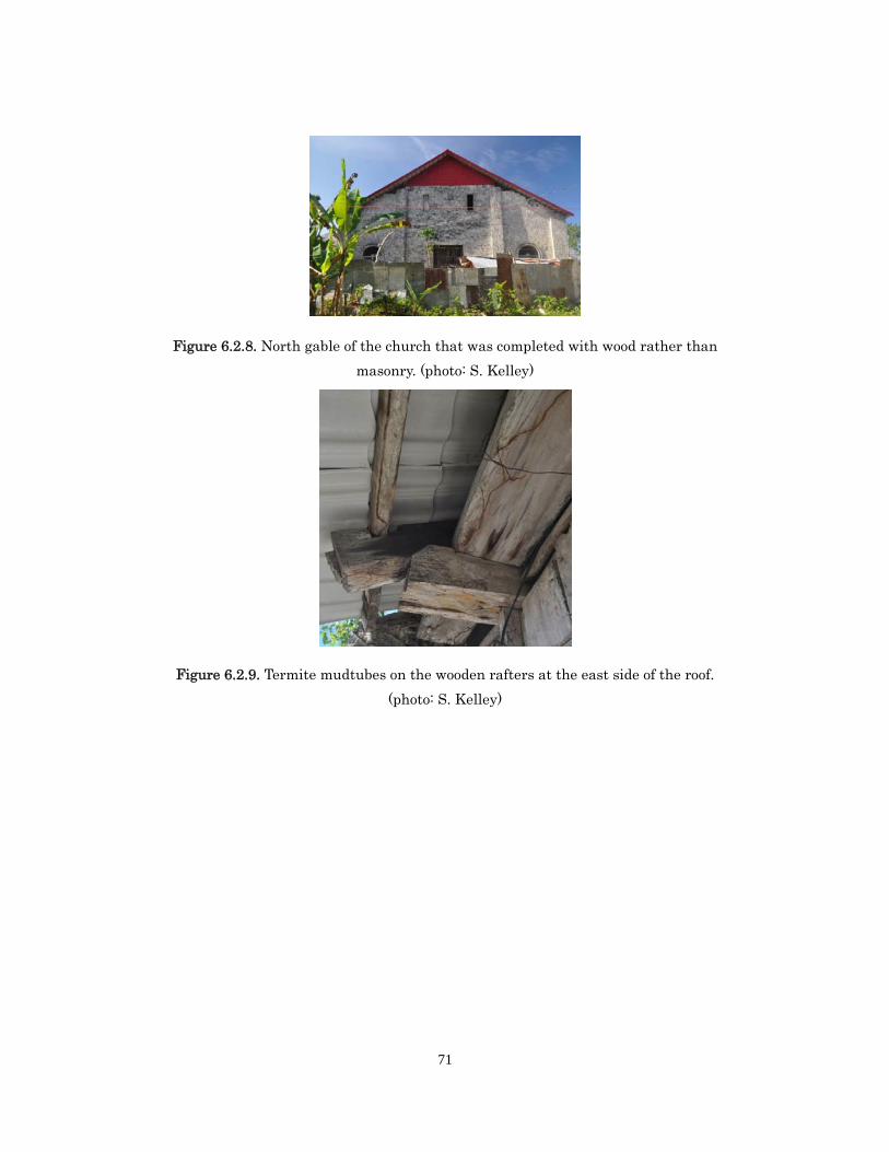
71
Figure 6.2.8. North gable of the church that was completed with wood rather than
masonry. (photo: S. Kelley)
Figure 6.2.9. Termite mudtubes on the wooden rafters at the east side of the roof.
(photo: S. Kelley)
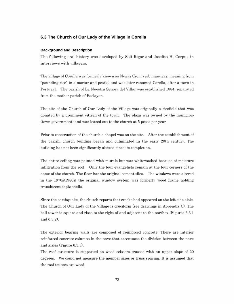
72
6.3 The Church of Our Lady of the Village in Corella
Background and Description
The following oral history was developed by Soli Rigor and Joselito H. Corpus in
interviews with villagers.
The village of Corella was formerly known as Nugas (from verb manugas, meaning from
“pounding rice” in a mortar and pestle) and was later renamed Corella, after a town in
Portugal. The parish of La Nuestra Senora del Villar was established 1884, separated
from the mother parish of Baclayon.
The site of the Church of Our Lady of the Village was originally a ricefield that was
donated by a prominent citizen of the town. The plaza was owned by the municipio
(town government) and was leased out to the church at 5 pesos per year.
Prior to construction of the church a chapel was on the site. After the establishment of
the parish, church building began and culminated in the early 20th century. The
building has not been significantly altered since its completion.
The entire ceiling was painted with murals but was whitewashed because of moisture
infiltration from the roof. Only the four evangelists remain at the four corners of the
dome of the church. The floor has the original cement tiles. The windows were altered
in the 1970s/1980s; the original window system was formerly wood frame holding
translucent capiz shells.
Since the earthquake, the church reports that cracks had appeared on the left side aisle.
The Church of Our Lady of the Village is cruciform (see drawings in Appendix C). The
bell tower is square and rises to the right of and adjacent to the narthex (Figures 6.3.1
and 6.3.2).
The exterior bearing walls are composed of reinforced concrete. There are interior
reinforced concrete columns in the nave that accentuate the division between the nave
and aisles (Figure 6.3.3).
The roof structure is supported on wood scissors trusses with an upper slope of 20
degrees. We could not measure the member sizes or truss spacing. It is assumed that
the roof trusses are wood.
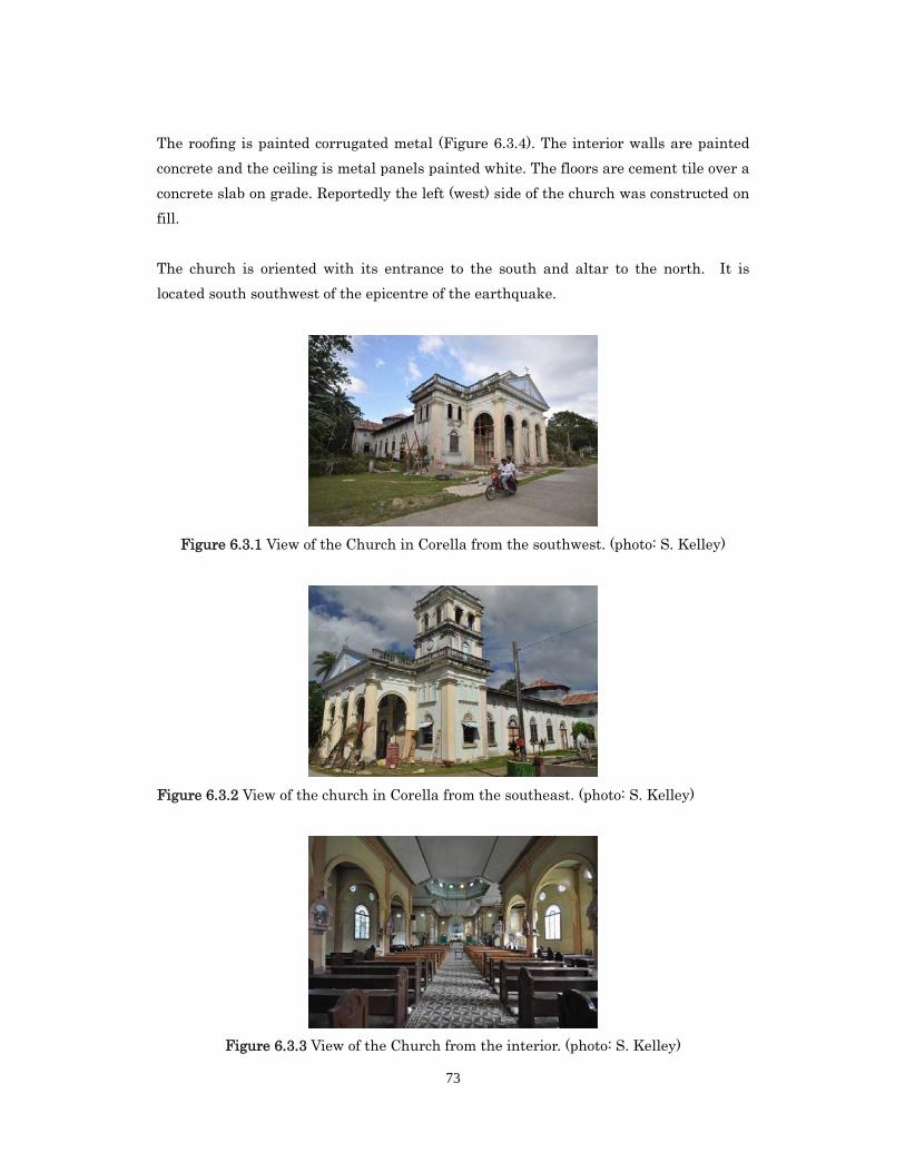
73
The roofing is painted corrugated metal (Figure 6.3.4). The interior walls are painted
concrete and the ceiling is metal panels painted white. The floors are cement tile over a
concrete slab on grade. Reportedly the left (west) side of the church was constructed on
fill.
The church is oriented with its entrance to the south and altar to the north. It is
located south southwest of the epicentre of the earthquake.
Figure 6.3.1 View of the Church in Corella from the southwest. (photo: S. Kelley)
Figure 6.3.2 View of the church in Corella from the southeast. (photo: S. Kelley)
Figure 6.3.3 View of the Church from the interior. (photo: S. Kelley)
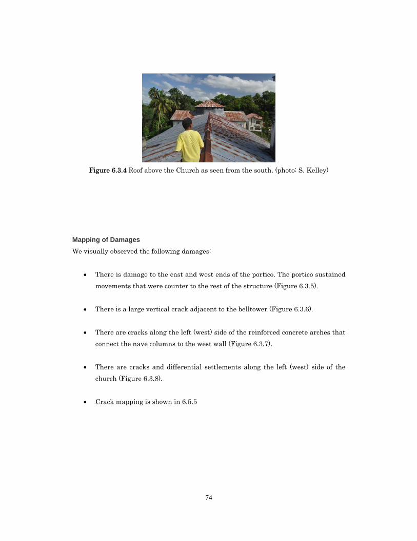
74
Figure 6.3.4 Roof above the Church as seen from the south. (photo: S. Kelley)
Mapping of Damages
We visually observed the following damages:
There is damage to the east and west ends of the portico. The portico sustained
movements that were counter to the rest of the structure (Figure 6.3.5).
There is a large vertical crack adjacent to the belltower (Figure 6.3.6).
There are cracks along the left (west) side of the reinforced concrete arches that
connect the nave columns to the west wall (Figure 6.3.7).
There are cracks and differential settlements along the left (west) side of the
church (Figure 6.3.8).
Crack mapping is shown in 6.5.5
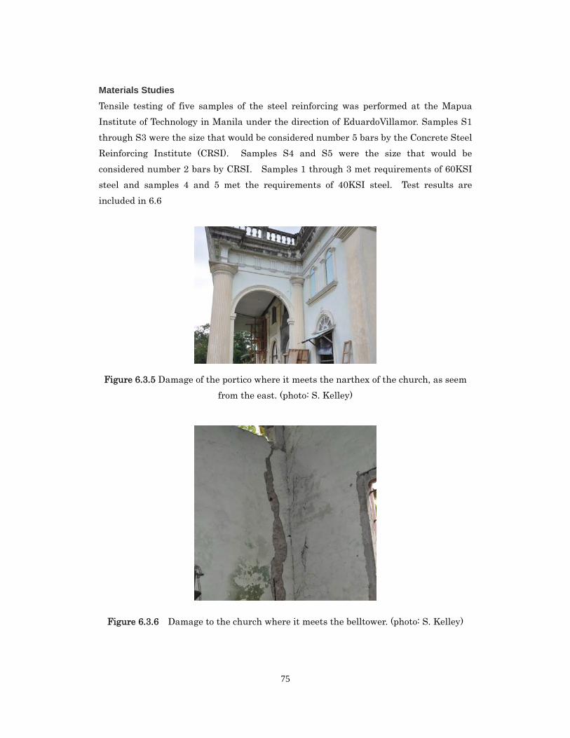
75
Materials Studies
Tensile testing of five samples of the steel reinforcing was performed at the Mapua
Institute of Technology in Manila under the direction of EduardoVillamor. Samples S1
through S3 were the size that would be considered number 5 bars by the Concrete Steel
Reinforcing Institute (CRSI). Samples S4 and S5 were the size that would be
considered number 2 bars by CRSI. Samples 1 through 3 met requirements of 60KSI
steel and samples 4 and 5 met the requirements of 40KSI steel. Test results are
included in 6.6
Figure 6.3.5 Damage of the portico where it meets the narthex of the church, as seem
from the east. (photo: S. Kelley)
Figure 6.3.6 Damage to the church where it meets the belltower. (photo: S. Kelley)
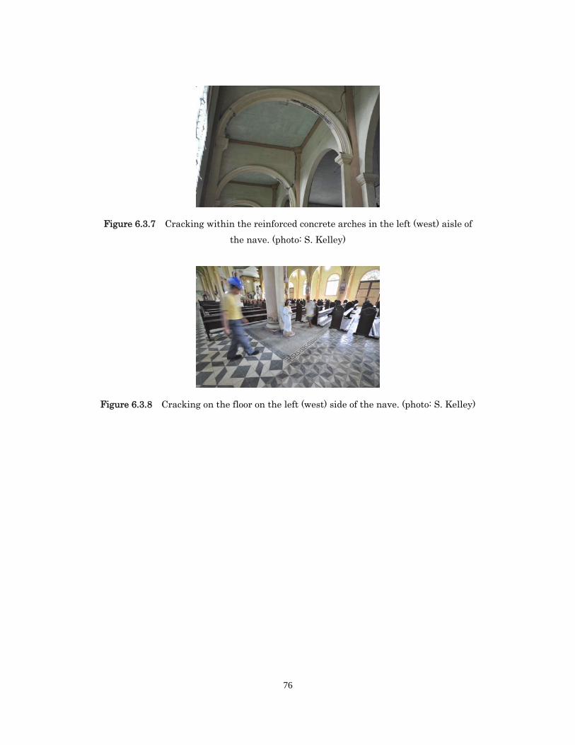
76
Figure 6.3.7 Cracking within the reinforced concrete arches in the left (west) aisle of
the nave. (photo: S. Kelley)
Figure 6.3.8 Cracking on the floor on the left (west) side of the nave. (photo: S. Kelley)
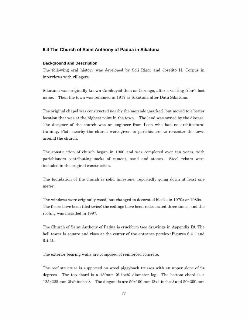
77
6.4 The Church of Saint Anthony of Padua in Sikatuna
Background and Description
The following oral history was developed by Soli Rigor and Joselito H. Corpus in
interviews with villagers.
Sikatuna was originally known Cambuyod then as Cornago, after a visiting friar’s last
name. Then the town was renamed in 1917 as Sikatuna after Datu Sikatuna.
The original chapel was constructed nearby the mercado (market), but moved to a better
location that was at the highest point in the town. The land was owned by the diocese.
The designer of the church was an engineer from Loon who had no architectural
training. Plots nearby the church were given to parishioners to re-center the town
around the church.
The construction of church began in 1900 and was completed over ten years, with
parishioners contributing sacks of cement, sand and stones. Steel rebars were
included in the original construction.
The foundation of the church is solid limestone, reportedly going down at least one
meter.
The windows were originally wood, but changed to decorated blocks in 1970s or 1980s.
The floors have been tiled twice; the ceilings have been redecorated three times, and the
roofing was installed in 1997.
The Church of Saint Anthony of Padua is cruciform (see drawings in Appendix D). The
bell tower is square and rises at the center of the entrance portico (Figures 6.4.1 and
6.4.2).
The exterior bearing walls are composed of reinforced concrete.
The roof structure is supported on wood piggyback trusses with an upper slope of 24
degrees. The top chord is a 150mm (6 inch) diameter log. The bottom chord is a
125x225 mm (5x9 inches). The diagonals are 50x100 mm (2x4 inches) and 50x200 mm
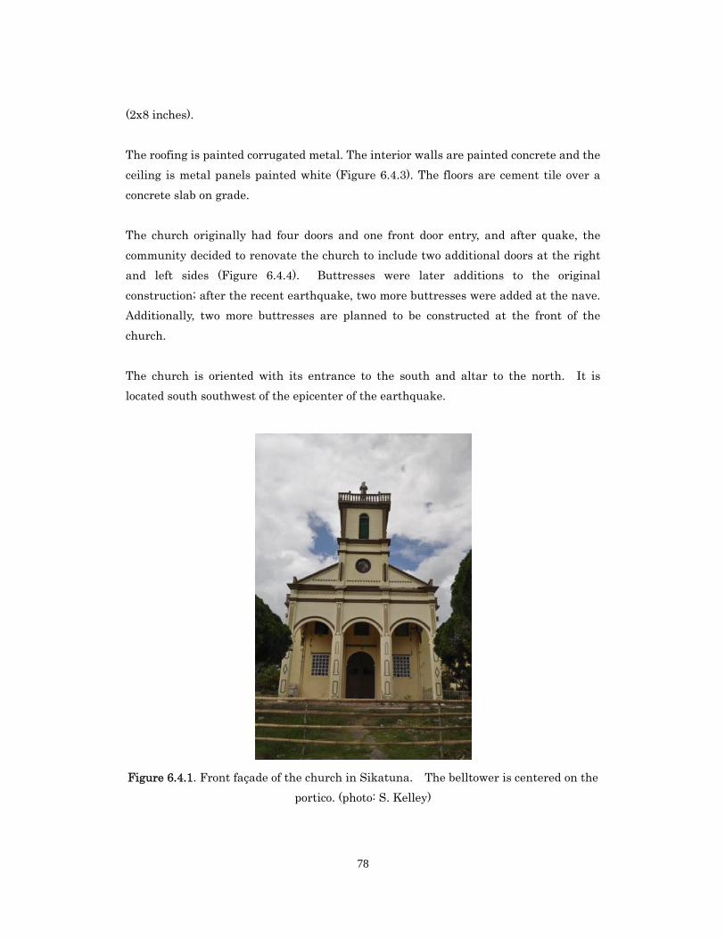
78
(2x8 inches).
The roofing is painted corrugated metal. The interior walls are painted concrete and the
ceiling is metal panels painted white (Figure 6.4.3). The floors are cement tile over a
concrete slab on grade.
The church originally had four doors and one front door entry, and after quake, the
community decided to renovate the church to include two additional doors at the right
and left sides (Figure 6.4.4). Buttresses were later additions to the original
construction; after the recent earthquake, two more buttresses were added at the nave.
Additionally, two more buttresses are planned to be constructed at the front of the
church.
The church is oriented with its entrance to the south and altar to the north. It is
located south southwest of the epicenter of the earthquake.
Figure 6.4.1. Front façade of the church in Sikatuna. The belltower is centered on the
portico. (photo: S. Kelley)
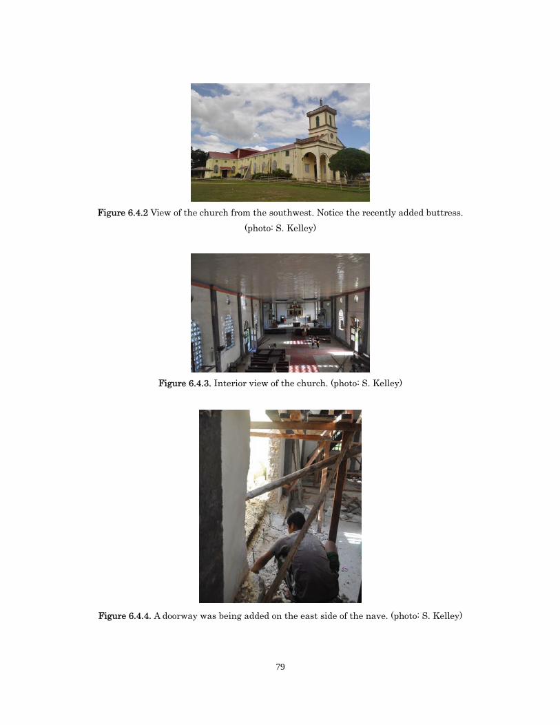
79
Figure 6.4.2 View of the church from the southwest. Notice the recently added buttress.
(photo: S. Kelley)
Figure 6.4.3. Interior view of the church. (photo: S. Kelley)
Figure 6.4.4. A doorway was being added on the east side of the nave. (photo: S. Kelley)
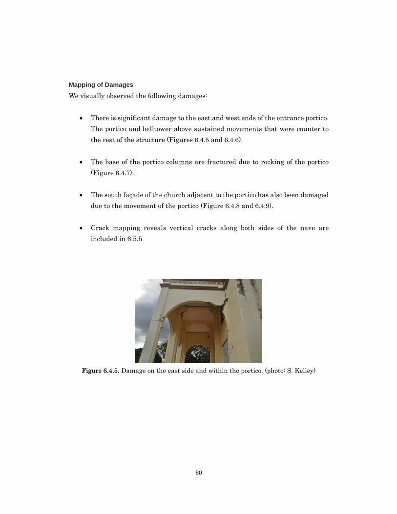
80
Mapping of Damages
We visually observed the following damages:
There is significant damage to the east and west ends of the entrance portico.
The portico and belltower above sustained movements that were counter to
the rest of the structure (Figures 6.4.5 and 6.4.6).
The base of the portico columns are fractured due to rocking of the portico
(Figure 6.4.7).
The south façade of the church adjacent to the portico has also been damaged
due to the movement of the portico (Figure 6.4.8 and 6.4.9).
Crack mapping reveals vertical cracks along both sides of the nave are
included in 6.5.5
Figure 6.4.5. Damage on the east side and within the portico. (photo: S. Kelley)
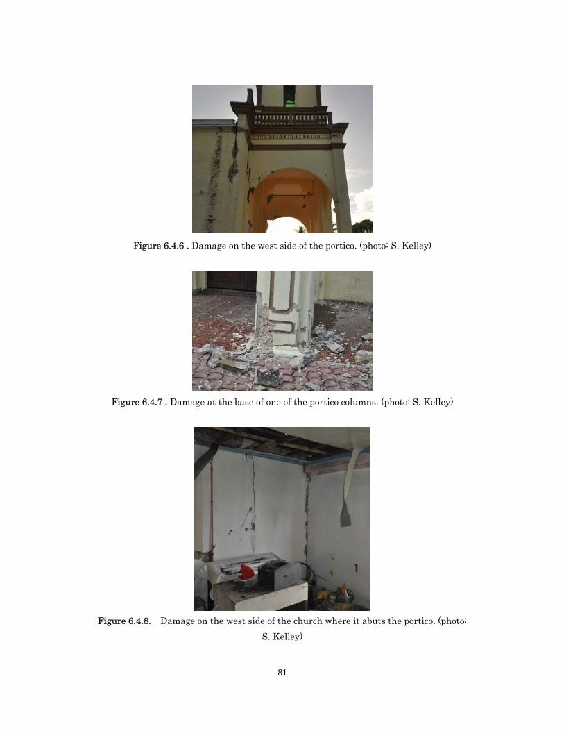
81
Figure 6.4.6 . Damage on the west side of the portico. (photo: S. Kelley)
Figure 6.4.7 . Damage at the base of one of the portico columns. (photo: S. Kelley)
Figure 6.4.8. Damage on the west side of the church where it abuts the portico. (photo:
S. Kelley)
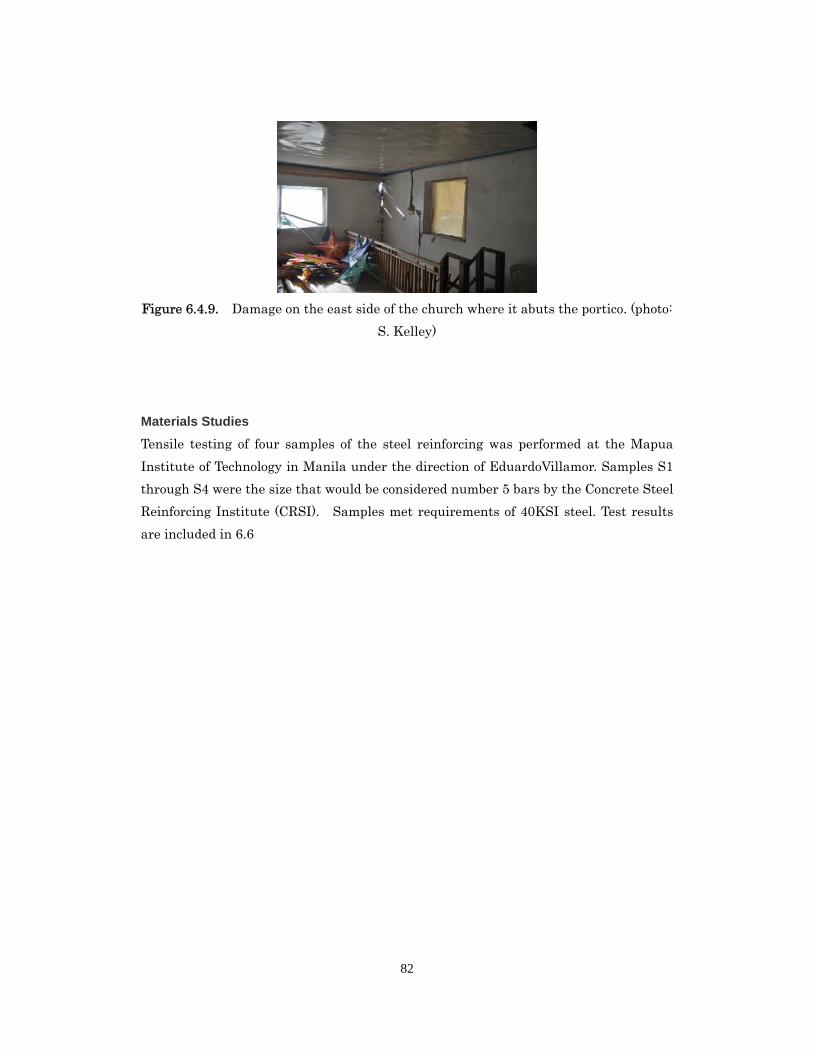
82
Figure 6.4.9. Damage on the east side of the church where it abuts the portico. (photo:
S. Kelley)
Materials Studies
Tensile testing of four samples of the steel reinforcing was performed at the Mapua
Institute of Technology in Manila under the direction of EduardoVillamor. Samples S1
through S4 were the size that would be considered number 5 bars by the Concrete Steel
Reinforcing Institute (CRSI). Samples met requirements of 40KSI steel. Test results
are included in 6.6
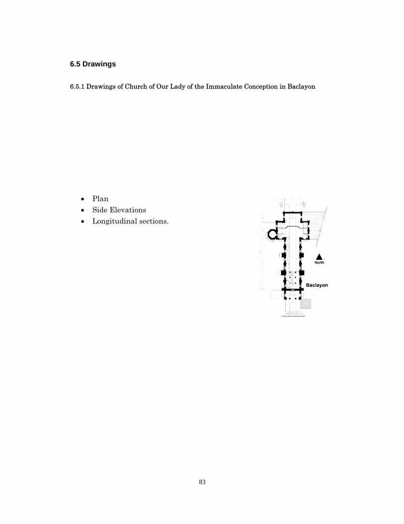
83
6.5 Drawings
6.5.1 Drawings of Church of Our Lady of the Immaculate Conception in Baclayon
Plan Side Elevations
Longitudinal sections.
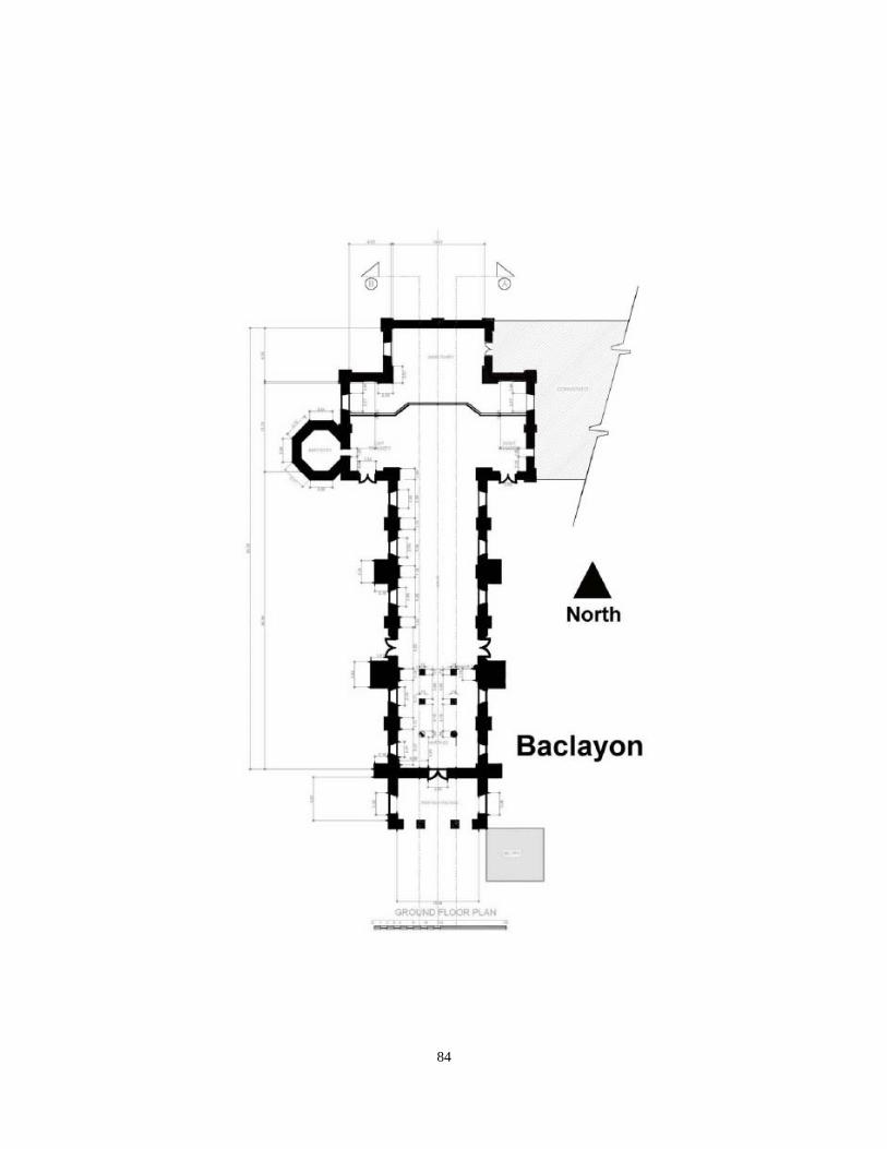
84
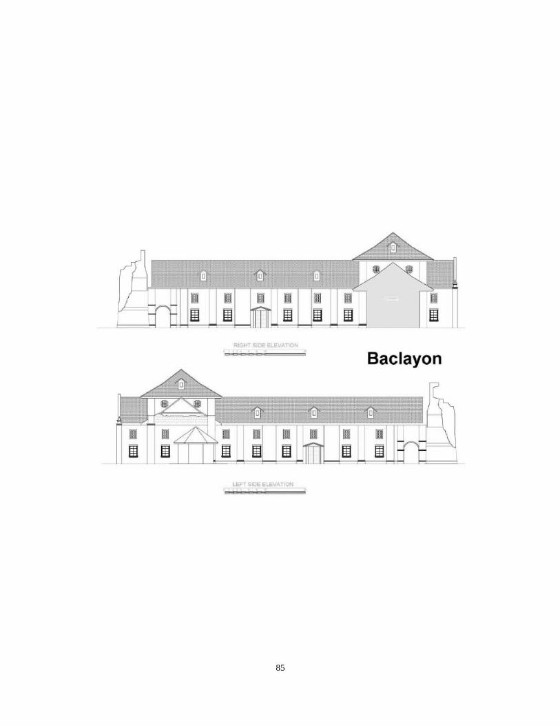
85
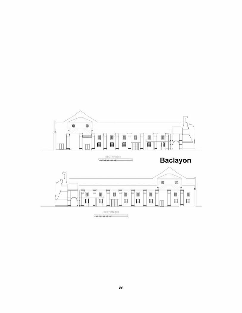
86
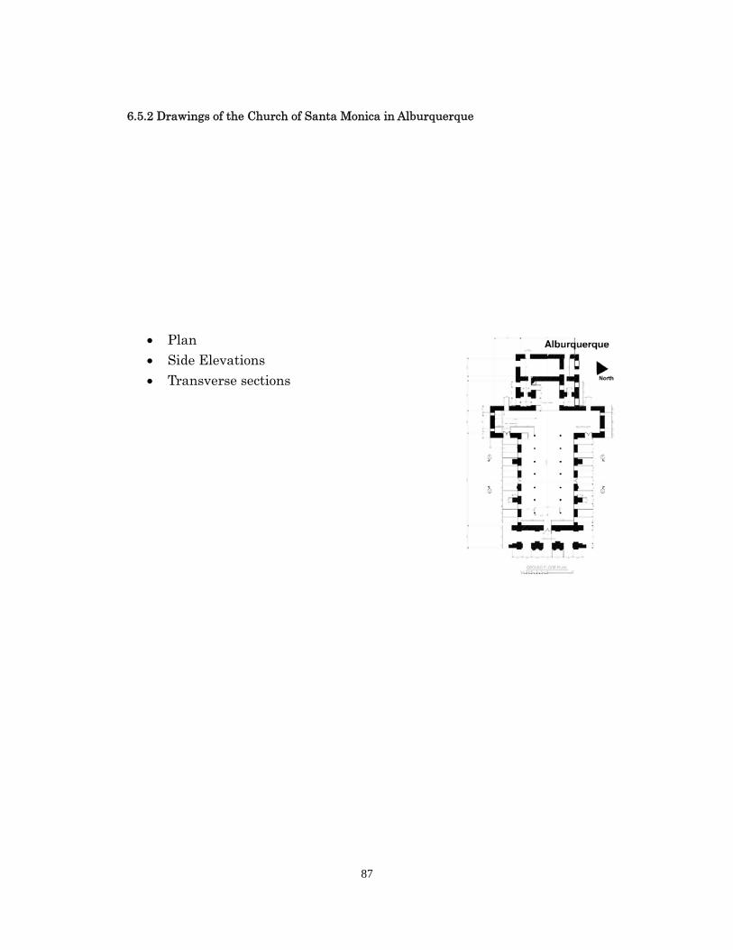
87
6.5.2 Drawings of the Church of Santa Monica in Alburquerque
Plan Side Elevations Transverse sections
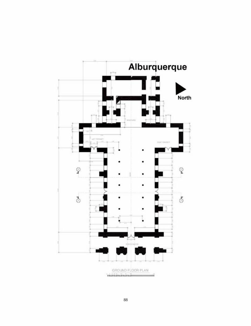
88
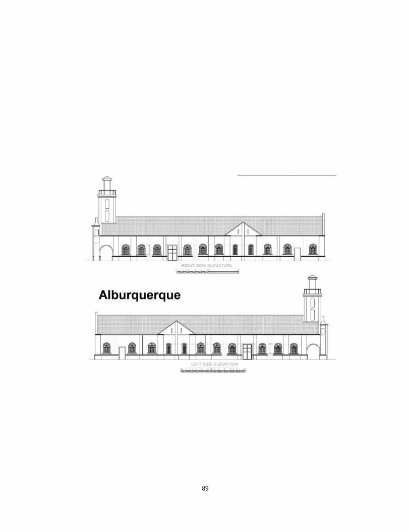
89
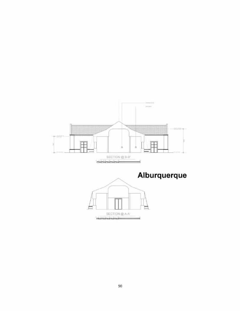
90
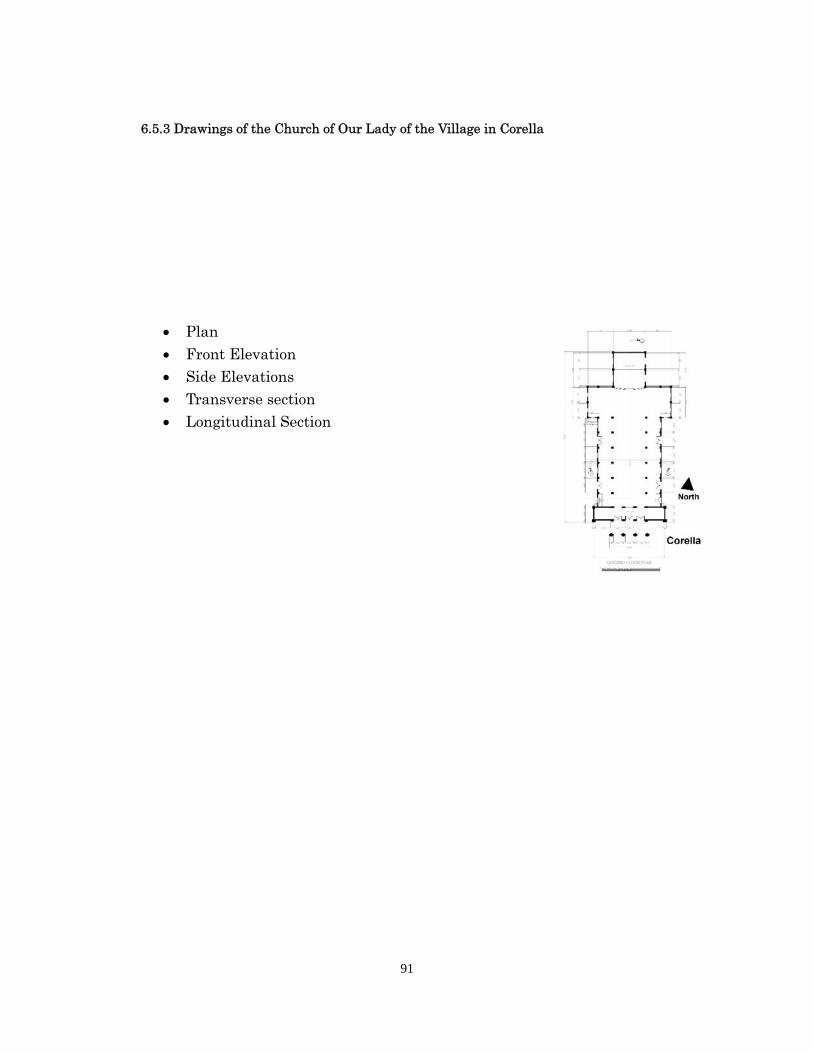
91
6.5.3 Drawings of the Church of Our Lady of the Village in Corella
Plan
Front Elevation Side Elevations Transverse section Longitudinal Section
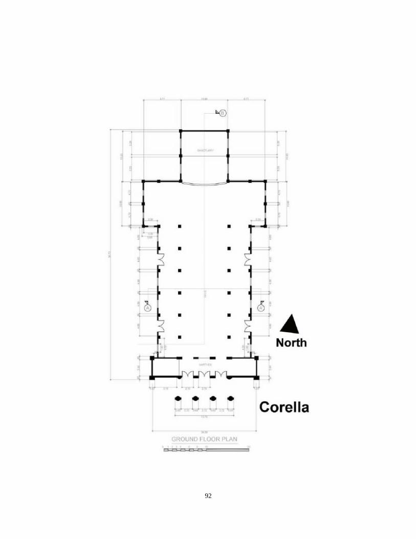
92
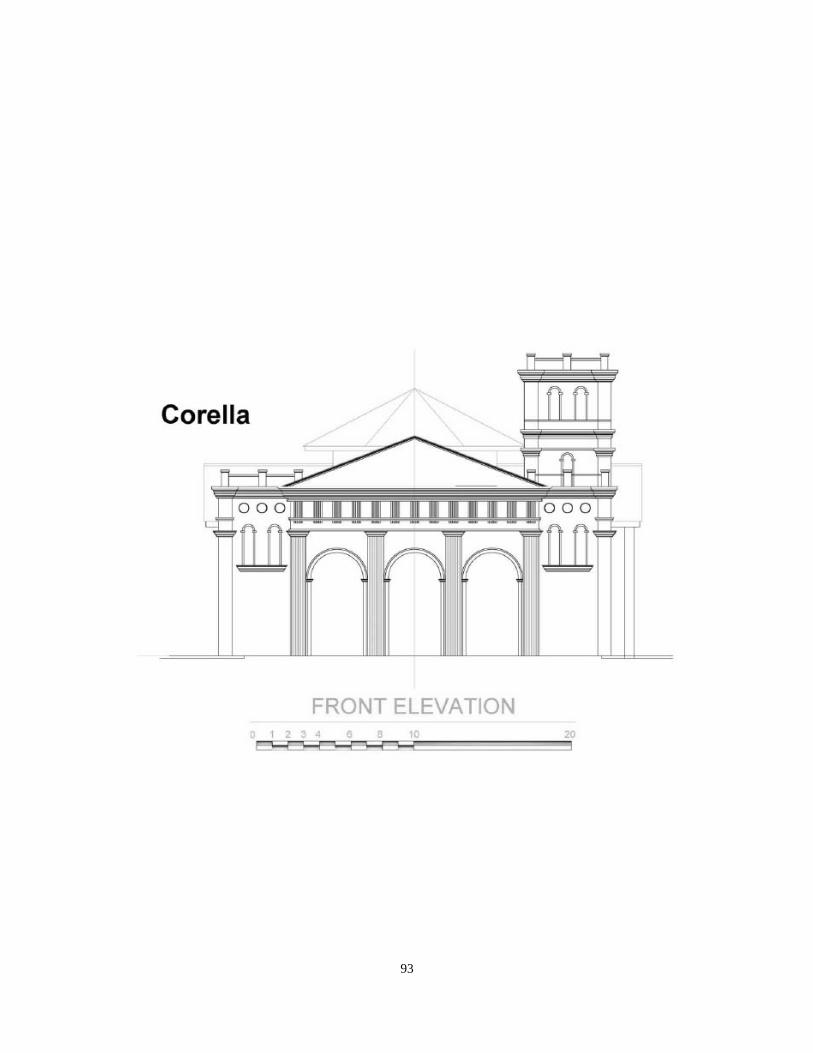
93
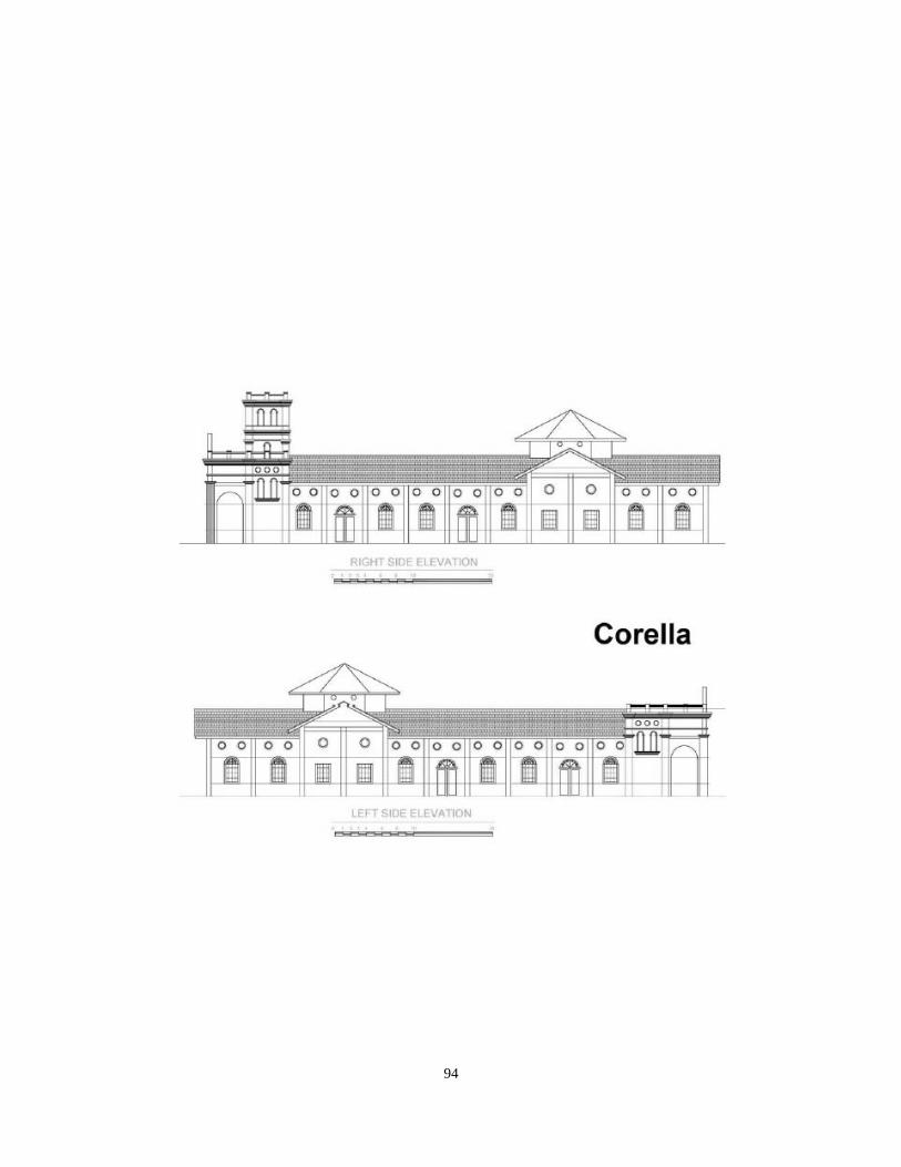
94
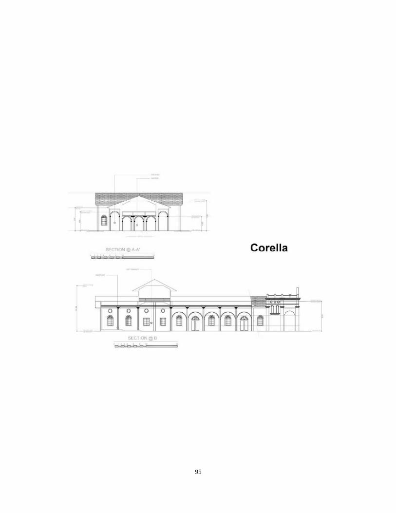
95
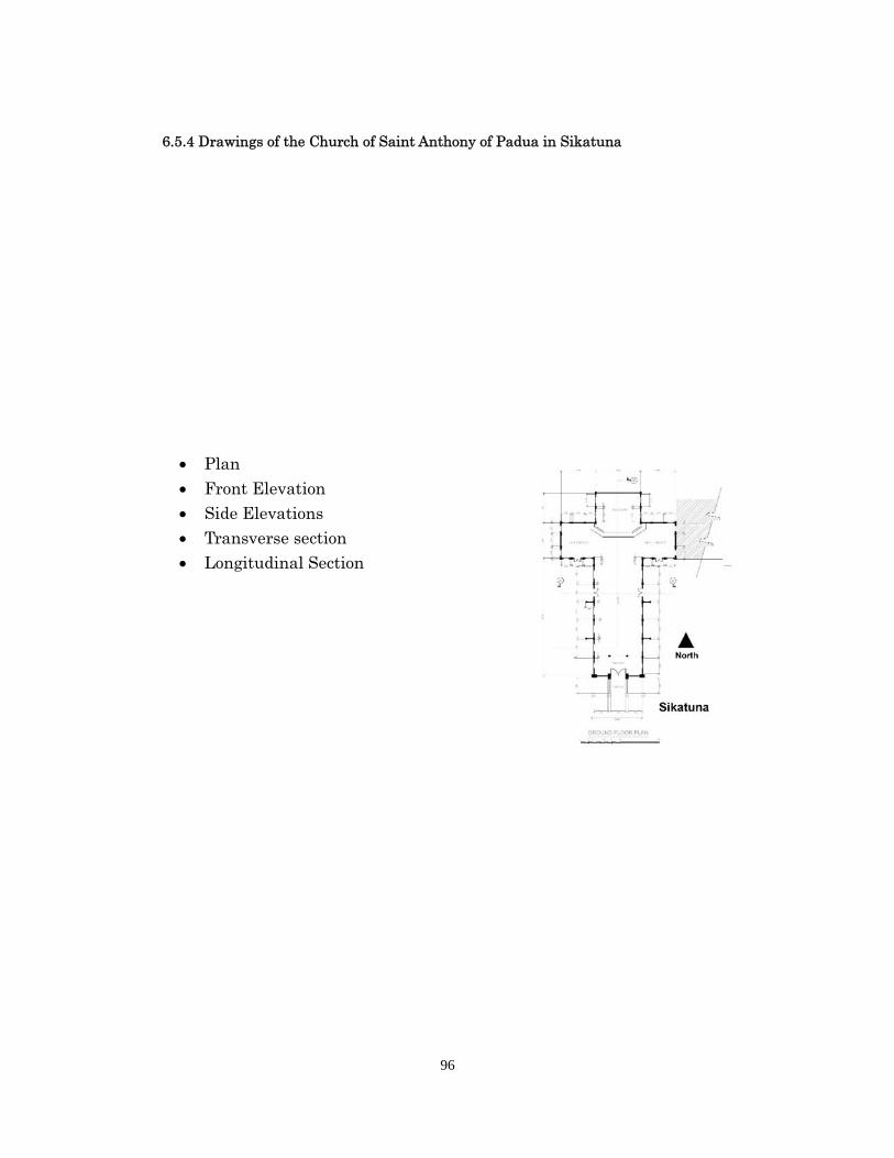
96
6.5.4 Drawings of the Church of Saint Anthony of Padua in Sikatuna
Plan
Front Elevation Side Elevations Transverse section Longitudinal Section
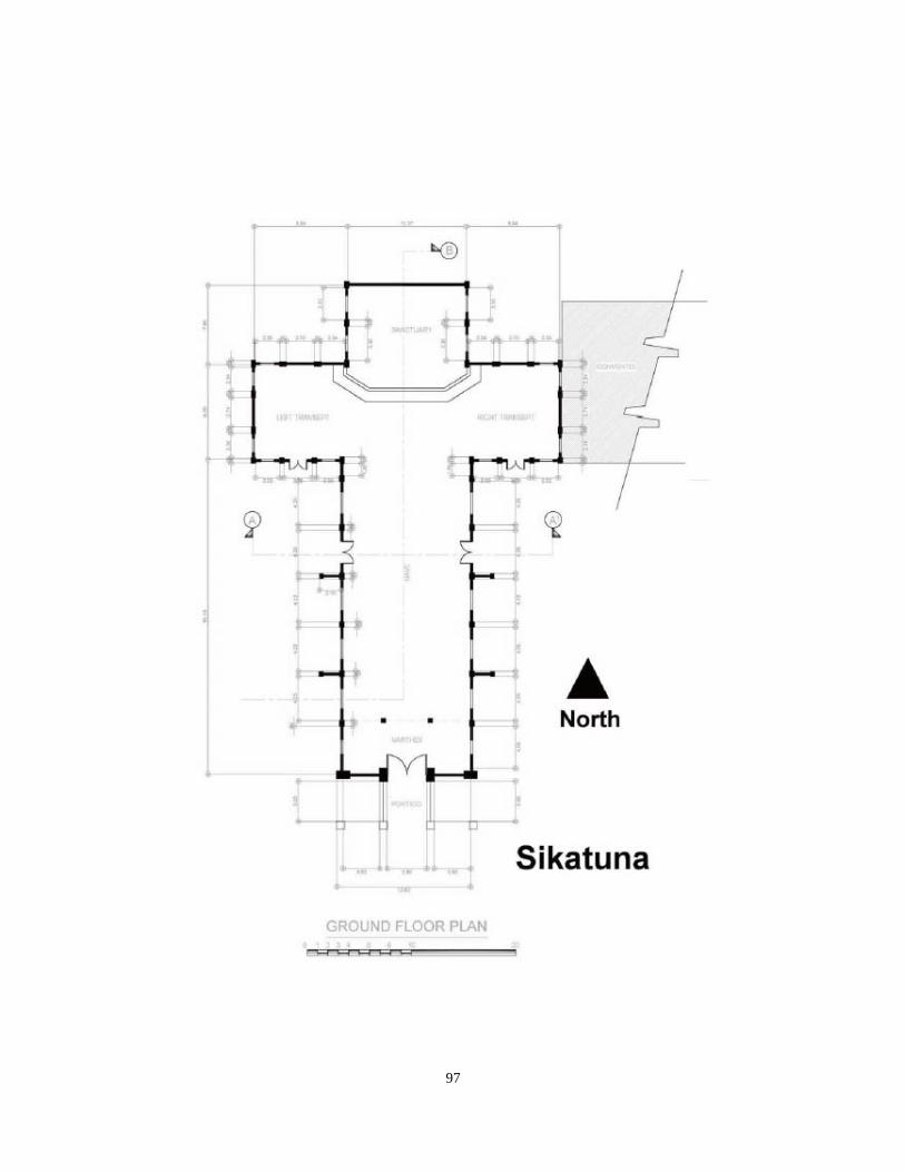
97
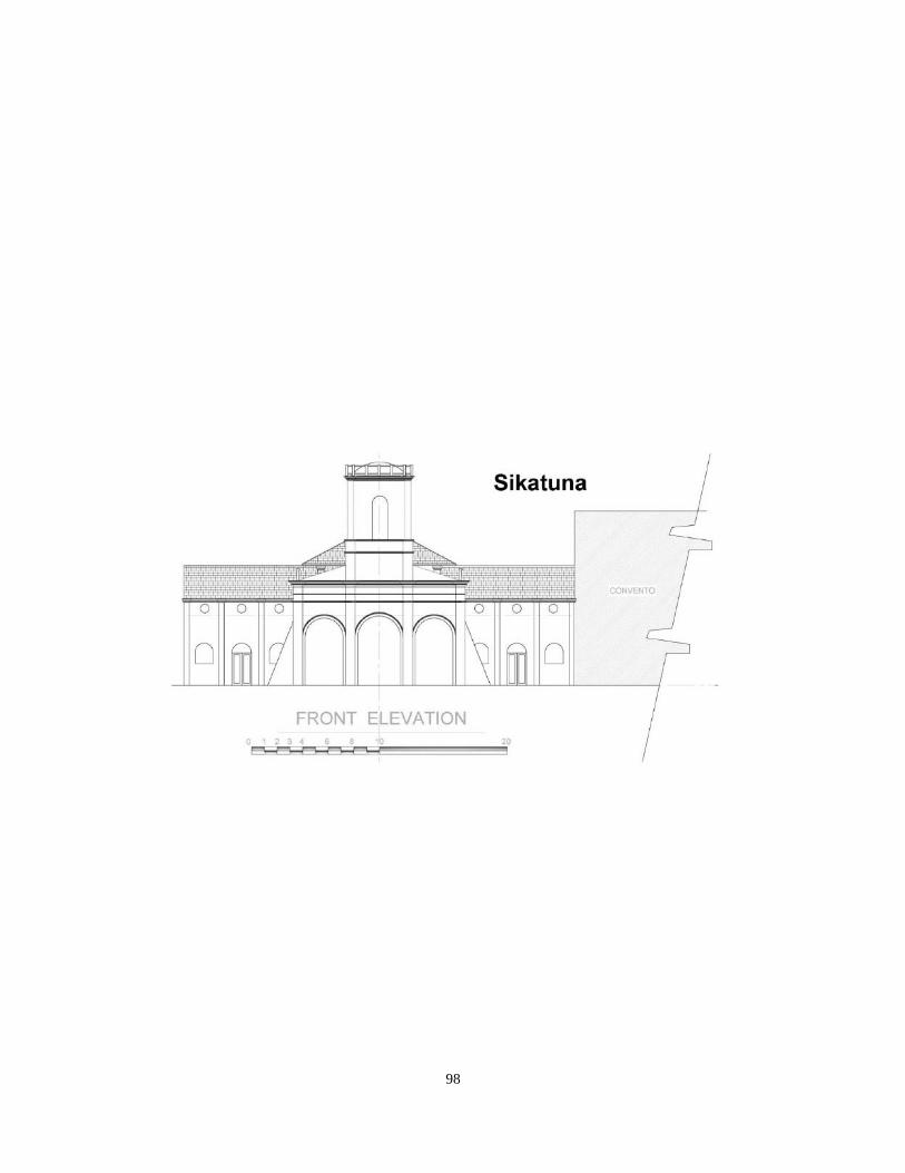
98
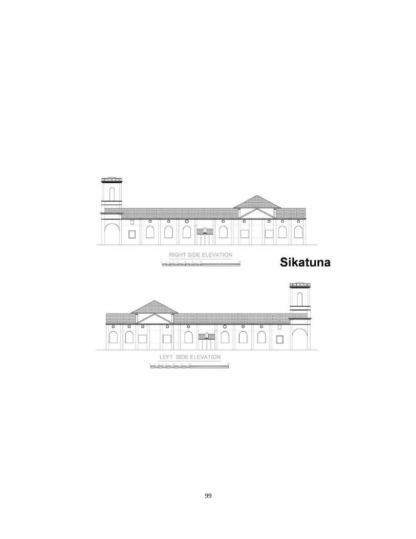
99
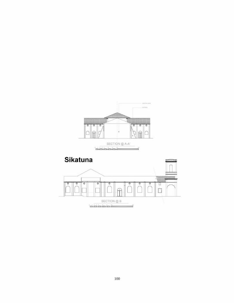
100
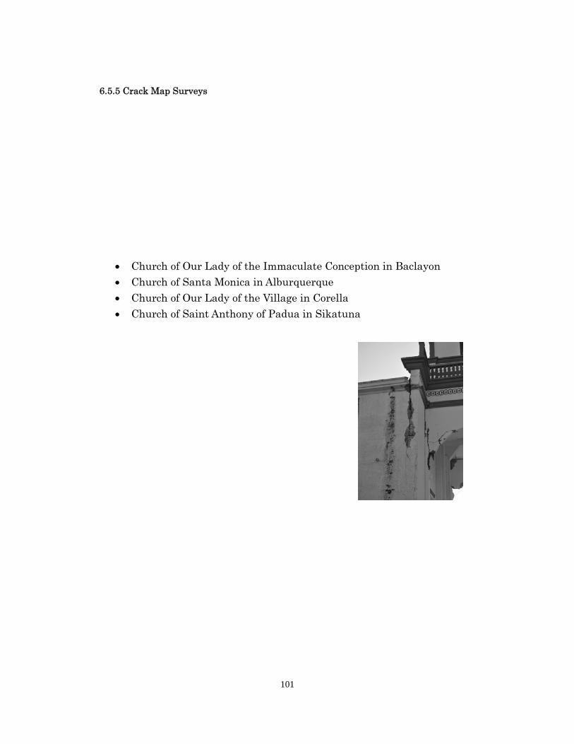
101
6.5.5 Crack Map Surveys
Church of Our Lady of the Immaculate Conception in Baclayon Church of Santa Monica in Alburquerque Church of Our Lady of the Village in Corella
Church of Saint Anthony of Padua in Sikatuna
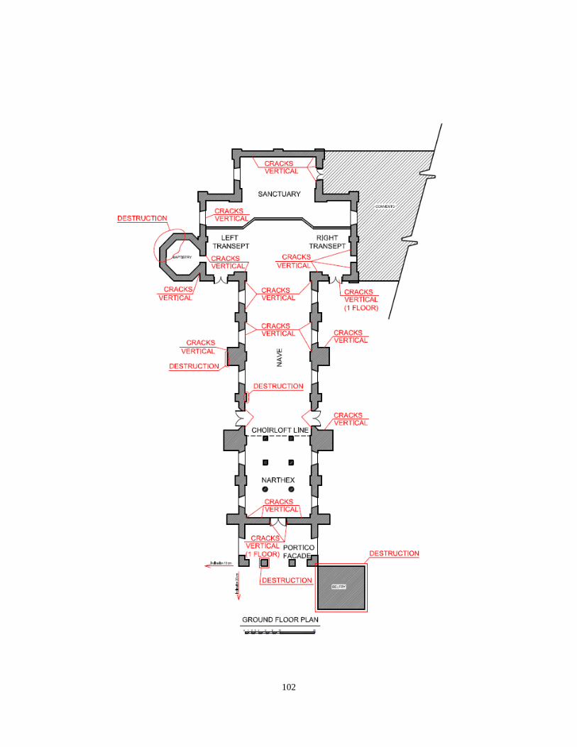
102
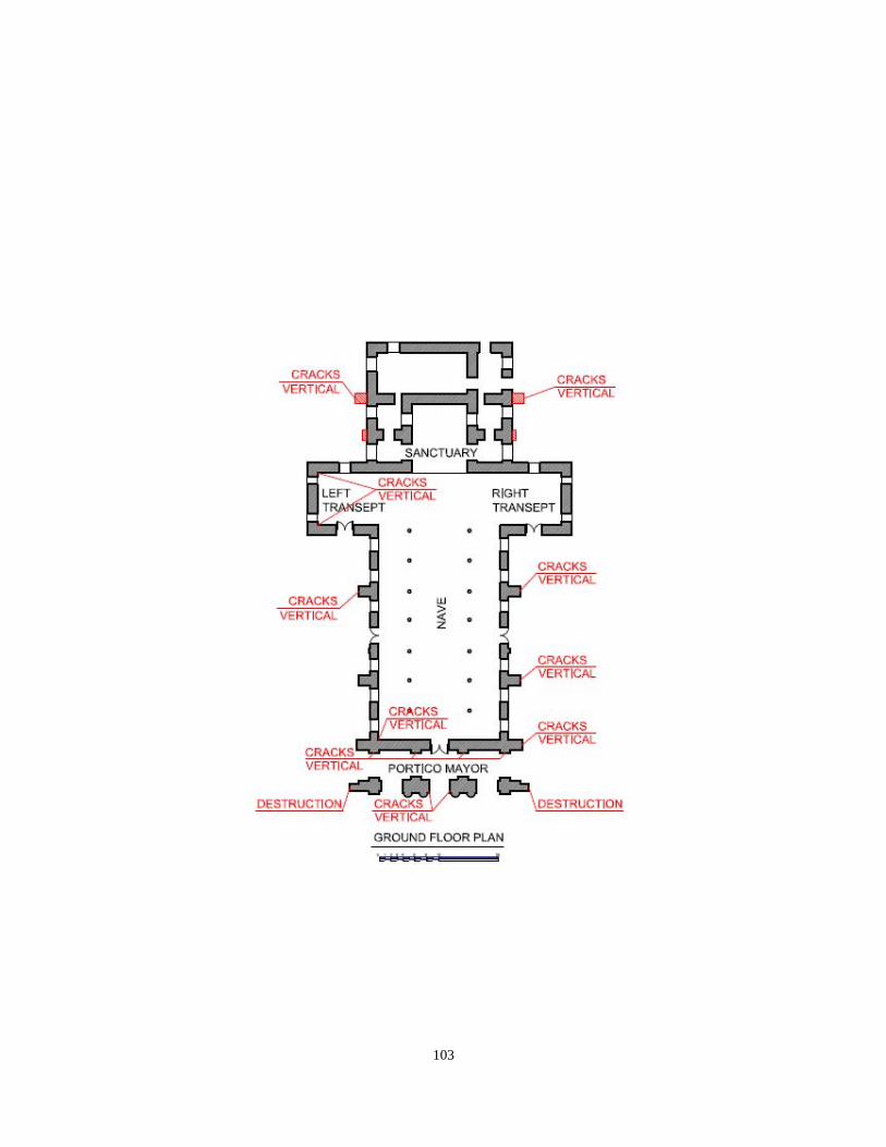
103
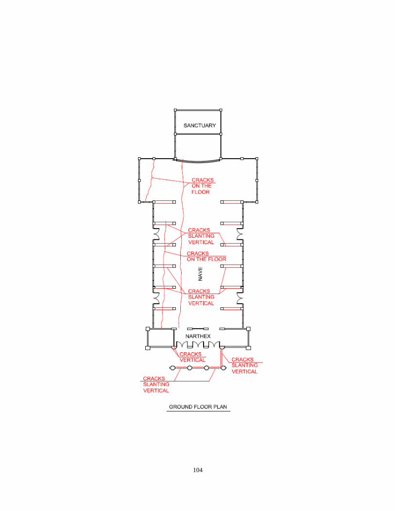
104
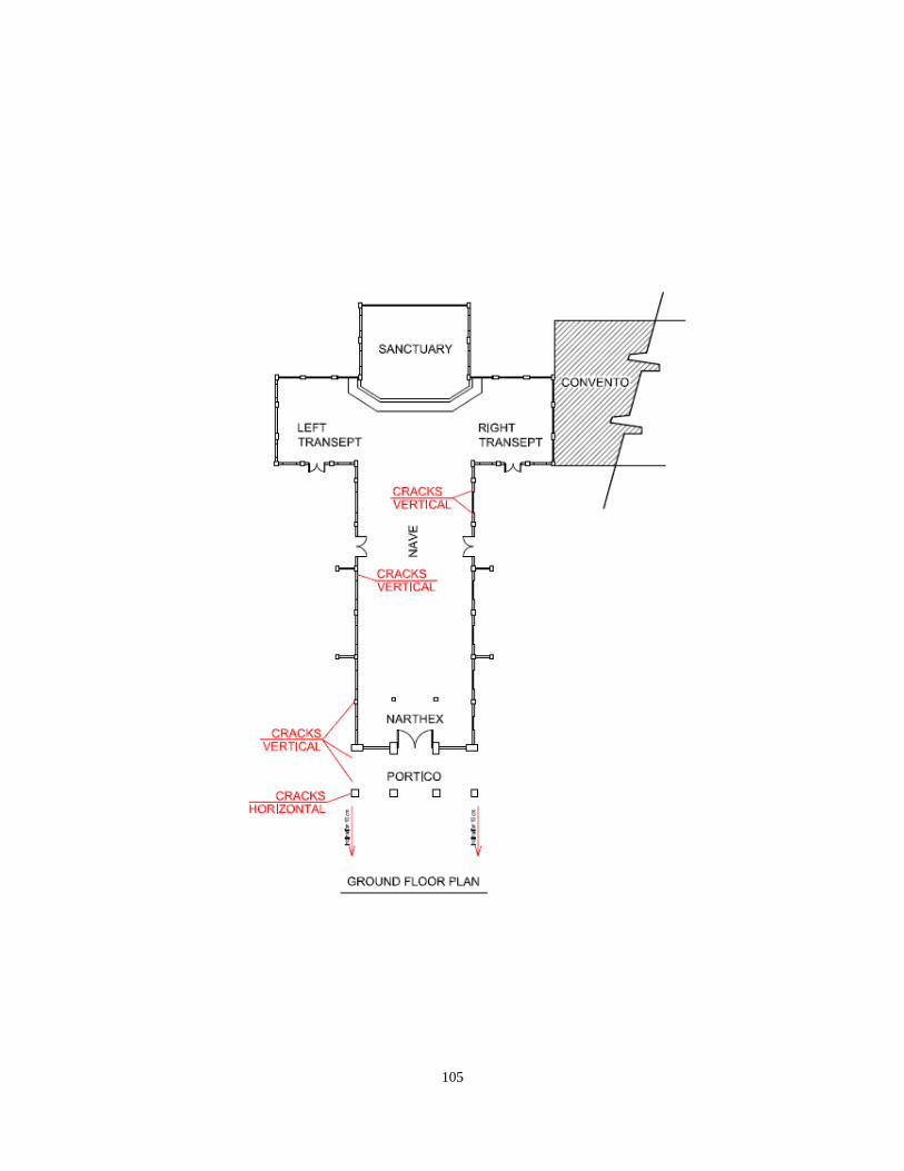
105
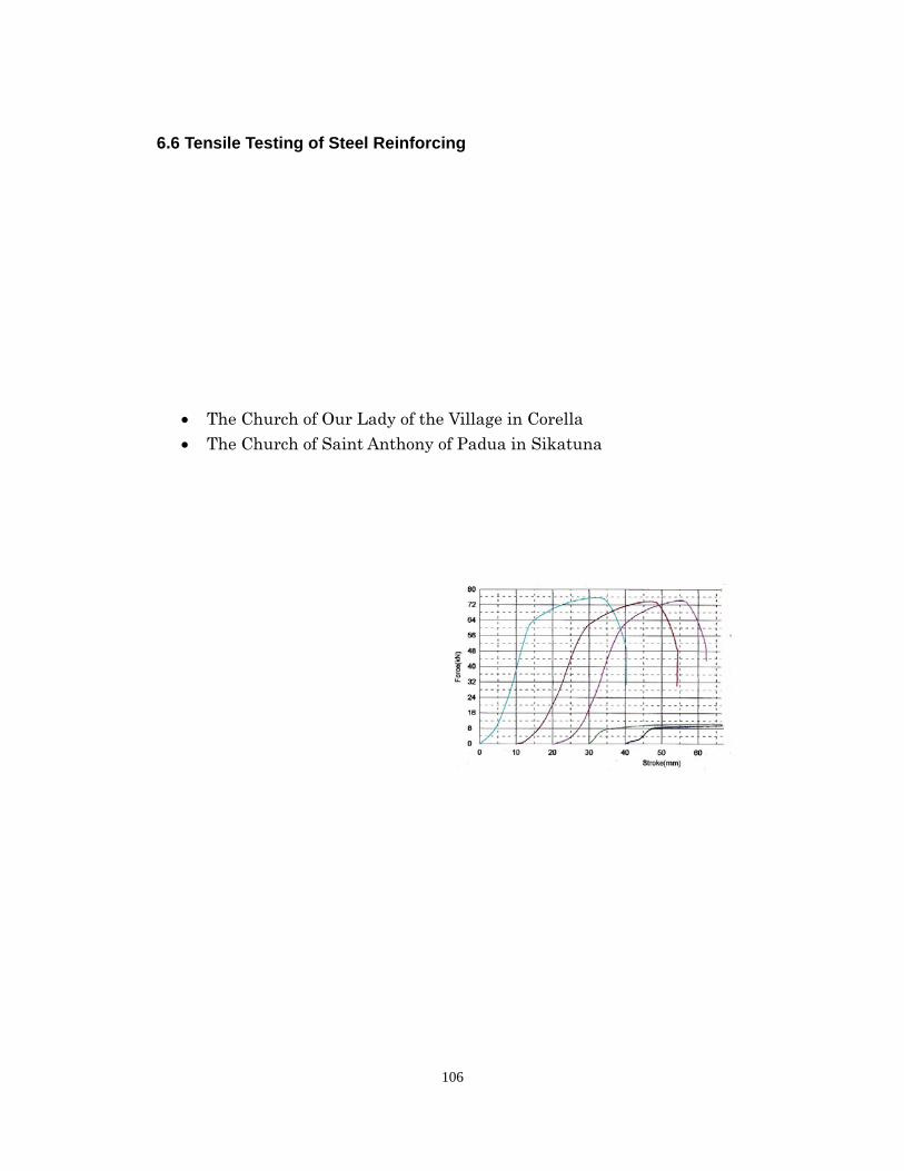
106
6.6 Tensile Testing of Steel Reinforcing
The Church of Our Lady of the Village in Corella The Church of Saint Anthony of Padua in Sikatuna
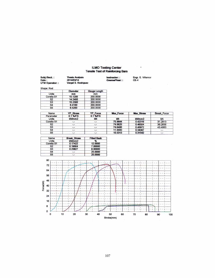
107
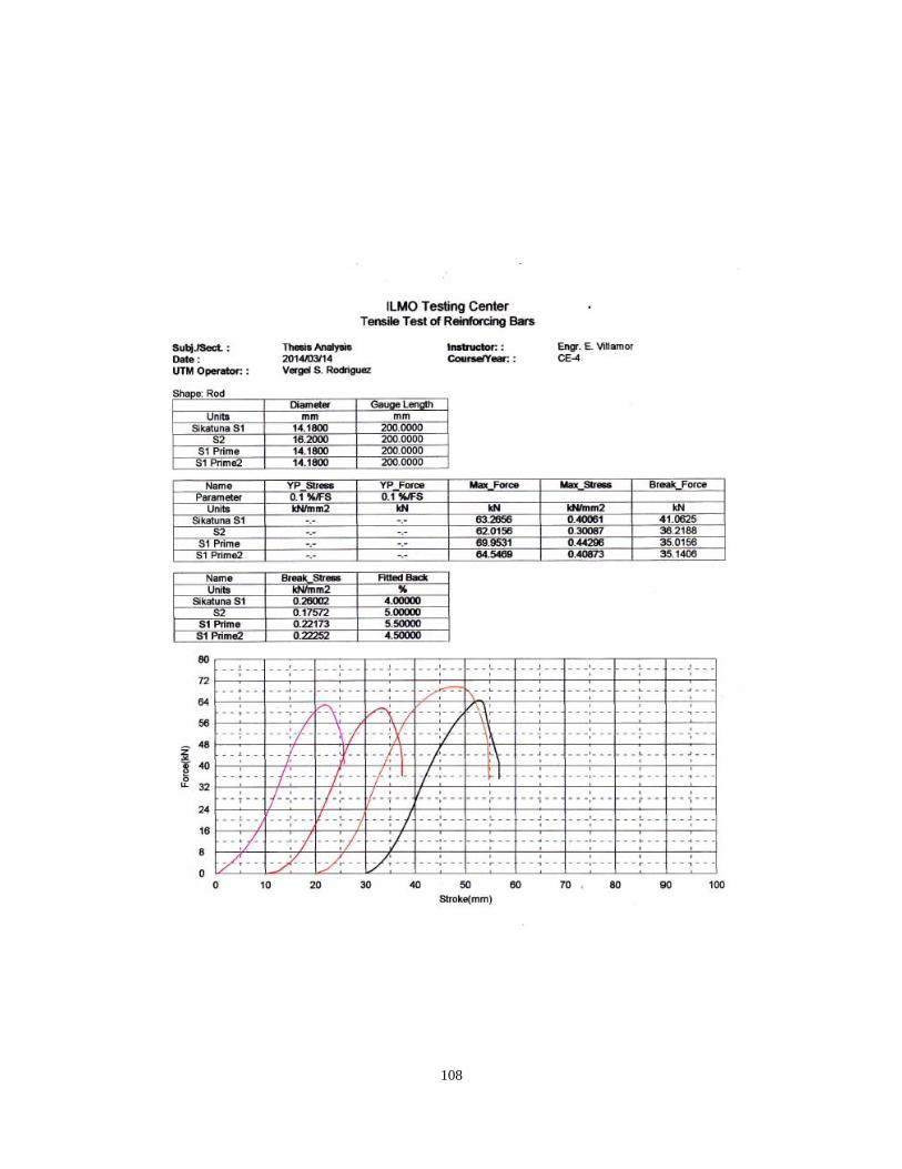
108
109
7. Conclusions for the churches All findings of 4 churches that were investigated are listed below Church of Our Lady of the Immaculate Conception in Baclayon Both the portico and the bell tower have collapsed and are damaged so severely that
they will need to be totally dismantled before they can be reconstructed. It is significant
that the portico was an addition to the church, and reveals that the addition was not
adequately attached to the original structure.
The masonry bearing walls appear to be undamaged other than the interior pilasters,
which do not seem to be adequately tied into the nave walls. These interior pilasters are
not part of the structure of the walls but a decorative applique. Other than the front
portico, two of the gables have collapsed at the top, revealing possible differential
movement between the walls and roof.
Any rehabilitation or reconstruction will require a seismic retrofit intervention to
strengthen the unreinforced masonry walls and tie the various elements of the
structure together (i.e. walls and roof) or to separate certain elements (i.e. sanctuary,
baptistry, bell tower). For any intervention, traditional methods and “soft” materials
should be given first consideration.
Church of Santa Monica in Alburquerque Significant damage was observed at the portico. It was observed that the stone portico
is built in tandem with a belltower that is composed entirely of reinforced concrete.
The belltower, being taller than the church nave moved independently of the church this
causing damage to the portico. In addition concrete elements that had been
incorporated into the façade also became loose and fell to the ground.
There was also significant damage at many of the buttresses. This seems to indicate
that the nave walls were in out of plane movement during the seismic event.
Termite activity was observed in the attic at the south end of the building.
Any rehabilitation or reconstruction will require a seismic retrofit intervention to
strengthen the unreinforced masonry walls and tie the various elements of the
structure together (i.e. walls and roof) or to separate certain elements (i.e. sanctuary,
110
baptistry, bell tower). For any intervention, traditional methods and “soft” materials
should be given first consideration.
Church of Our Lady of the Village in Corella There was observable damage to the portico at the south end of the church. In addition
there was damage to the wall structure where it about the belltower indicating that the
tower had a period that was distinct from the church.
The church was reportedly built on fill on the west side. In this area there was
settlement that is observable on the floor on the left side of the nave. In addition the
cracking of the concrete vaults on the west side of the nave are probably related to this
differential settlement.
Any rehabilitation or reconstruction will require a seismic retrofit intervention to
strengthen the damaged concrete elements and tie the various elements of the structure
together (i.e. walls and roof) or to separate certain elements (i.e. sanctuary, portico, bell
tower). For any intervention, reinforced concrete would be the appropriate material.
Church of Saint Anthony of Padua in Sikatuna
There was significant damage to the portico at the south end of the church. In addition
there was significant damage to the wall structure where it abuts the portico indicating
that the portico and belltower had a period that was distinct from the church.
Any rehabilitation or reconstruction will require a seismic retrofit intervention to
strengthen the damaged concrete elements and tie the various elements of the structure
together (i.e. walls and roof) or to separate certain elements (i.e. sanctuary, baptistry,
bell tower). For any intervention, reinforced concrete would be the appropriate material.
111
Summary Taking into account that these 4 churches don't necessarily represent all churches in
Bohol or Philippines, however, we could summarize the damage and recommendation as
follows.
Cause of Damage Tightness: It is observed in the damage of inadequate tight ness between the building elements
such as interior pilasters and nave walls (Baclayon) and walls and roofs that might
cause the collapse of gables (Bacrayon).
Differential Movement: Differential movements are observed in building elements that caused the damage in
the structures such as bell tower and nave wall (Alburquerque), buttress and nave wall
(Alburquerque), tower and church (Collera) and Portico, bell tower and church
(Silatuna).
Others: There are other observation of termed activity in the attic (Alburquerque) and allegedly
built on the fill that caused the cracking in the concrete vaults (Corella).
Intervention: Rehabilitation or reconstruction will require a seismic retrofit to strengthen
unreinforced or concrete elements.
In the intervention, it should be careful to tie or separate structural elements.
It should be careful for the material/method of intervention. For some churches,
traditional methods (In this case unreinforced masonry walls with buttresses instead of
concrete) and soft materials (use of lime mortars rather than Portland cement mortars)
should be given first consideration, for others, reinforced concrete would be the
appropriate material.
112
References
[1] PHIVOLCS Seismic Monitoring Network, http://www.phivolcs.dost.gov.ph/,
(April.2014)
[2] The Japan Building Disaster Prevention Association: Guideline for Post-earthquake
Damage Evaluation and Rehabilitation, 2002. (in Japanese)
[3] The Japan Building Disaster Prevention Association: Standard for Seismic
Evaluation of Existing Reinforced Concrete Buildings, 2005.
[4] Architectural Institute of Japan: AIJ standard for structural calculation of reinforced
concrete structures, 2010. (in Japanese)
[5] T. Saito: STERA3D Technical Manual Ver. 3.3,
http://www.rc.ace.tut.ac.jp/saito/software-e.html (2014.6)
[6] Construction Norms & Regulations 2.03.01-84* Concrete and Reinforced Concrete
Structures. Moscow, 1992.
[7] CN RK 1.04-04-2002 Inspection and Assessment of Technical Condition of Buildings
and Structures. Almaty, 2002.
[8] Data on testing the material samples obtained by the MAPUA Institute of
Technology of Philippines.
[9] Construction Norms & Regulations RK 2.03-30-2006 Construction in Seismic
Districts. Almaty, 2006.

113
Annex
Mission member
UNESCO-IPRED
1. Soichiro Yasukawa (UNESCO Paris) coordinator for experts
Programme Specialist, Earth Science and Geohazard Risk Reduction, Natural
Science Sector, UNESCO, Paris
2. Mr. Ruslanzhan Sadyrov (Kazakhstan)
Institute of Seismology, Ministry of Education and Sciences
3. Mr. Kanatbay Ryskulov (Kazakhstan)
Institute of Seismology, Ministry of Education and Sciences
4. Tomoya Matsui (Japan) Toyohashi Institute of Technology
5. Koichi Kusunoki (Japan) Tokyo University (Yokohama national University
during the mission)
6. Mr. Stephen Kelly (USA) Historic Preservation Specialist (Wiss, Janney,
Elstener Associate, Inc during the mission)
UNESCO National Commission
1. Dr. Virginia A. Miralao
Secretary-General, UNESCO National Commission of the Philippines
2. Dr. Reynaldo S. Vea
Chairman, S&T Committee
UNESCO National Commission of the Philippines and
President, MAPUA Institute of Technology
3. Dr. Mario Aurelio
Head, Structural Geology and Tectonics Laboratory
National Institute of Geological Sciences
University of the Philippines, Diliman, Quezon City, Philippines
4. Engr. Bienvenido Cervantes
Professor, Civil Engineering and Environmental Division
MAPUA Institute of Technology
5. Engr. Eduardo Villamor
Professor, Civil Engineering and Environmental Division
MAPUA Institute of Technology
6. Mr. Freddie A. Blanco
Development Management Officer, UNESCO National Commission of the
114
Philippines
Bohol Partners
1. Fr. Ted Torralba
Secretary, CBCP Permanent Committee on Church Heritage (PCCH)
Archdiocese of Tagbilaran
2. Arch. Anthony Manding
Coordinator of the Diocese of Tagbilaran's Commission for the Cultural
Heritage of the Church
3. Mr. Joselito “JJ” Corpus
Heritage Conservator
4. Ms. Socorro T. Rigor
Diocese of Tagbilaran
5. Mr. Lemuel Barol
Cogon High School (Evening Class)
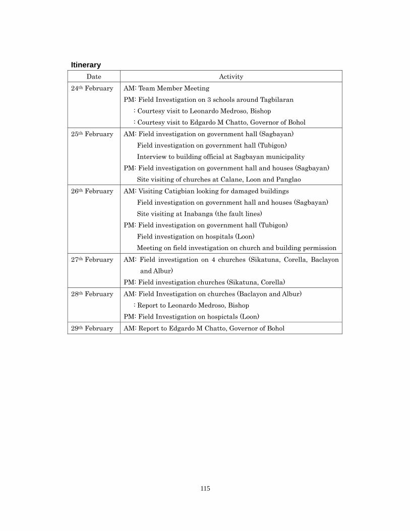
115
Itinerary
Date Activity
24th February AM: Team Member Meeting
PM: Field Investigation on 3 schools around Tagbilaran
: Courtesy visit to Leonardo Medroso, Bishop
: Courtesy visit to Edgardo M Chatto, Governor of Bohol
25th February AM: Field investigation on government hall (Sagbayan)
Field investigation on government hall (Tubigon)
Interview to building official at Sagbayan municipality
PM: Field investigation on government hall and houses (Sagbayan)
Site visiting of churches at Calane, Loon and Panglao
26th February AM: Visiting Catigbian looking for damaged buildings
Field investigation on government hall and houses (Sagbayan)
Site visiting at Inabanga (the fault lines)
PM: Field investigation on government hall (Tubigon)
Field investigation on hospitals (Loon)
Meeting on field investigation on church and building permission
27th February AM: Field investigation on 4 churches (Sikatuna, Corella, Baclayon
and Albur)
PM: Field investigation churches (Sikatuna, Corella)
28th February AM: Field Investigation on churches (Baclayon and Albur)
: Report to Leonardo Medroso, Bishop
PM: Field Investigation on hospictals (Loon)
29th February AM: Report to Edgardo M Chatto, Governor of Bohol
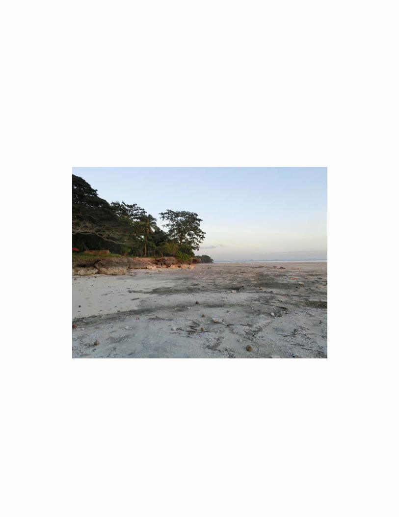

-