replacing an npu
DESCRIPTION
Replacing an NPUTRANSCRIPT
Replacing an NPUMINI-LINK TN ETSI
OPERATING INSTRUCTIONS
35/1543-HRA 901 20-V11 Uen E1

Copyright
© Ericsson AB 2009–2014. All rights reserved. No part of this document may bereproduced in any form without the written permission of the copyright owner.
Disclaimer
The contents of this document are subject to revision without notice due tocontinued progress in methodology, design and manufacturing. Ericsson shallhave no liability for any error or damage of any kind resulting from the useof this document.
35/1543-HRA 901 20-V11 Uen E1 | 2014-02-04
Contents
Contents
1 Introduction 1
2 Prerequisites 1
2.1 Safety Information 1
2.2 Required Tools and Equipment 1
2.3 Required Documentation 2
3 Flowchart 2
4 Replacing an NPU 6
4.1 Preparing a Site Visit 64.1.1 Identifying Current Hardware and Software 64.1.2 Checking Compatibility 64.1.3 Placing Files on an FTP Server 64.1.4 Uploading Configuration File 7
4.2 Preparing the NE on Site 74.2.1 Starting the Local FTP Server 74.2.2 Verifying the Software Upgrade Preferences 74.2.3 Upgrading the Software 8
4.3 Replacing the Hardware 84.3.1 Replacing an NPU1 C 94.3.2 Replacing an NPU3 B/C/D 144.3.3 Replacing an NPU with Ethernet Switch Protection
Configured 20
4.4 Concluding Routines 254.4.1 Checking Active Alarms 254.4.2 Checking Current SBL 264.4.3 Handling Faulty Units 26
Reference List 27
35/1543-HRA 901 20-V11 Uen E1 | 2014-02-04

Replacing an NPU
35/1543-HRA 901 20-V11 Uen E1 | 2014-02-04
Prerequisites
1 Introduction
This instruction describes how to replace NPU plug-in units. Hardwaremanagement is described in HW Management Overview, Reference [7].
2 Prerequisites
This chapter includes information about required preparations before performingany replacement of hardware.
2.1 Safety Information
Make sure that the information in the following documents has been understoodby the persons performing the procedures:
• Personal Health and Safety Information, Reference [10]
• System Safety Information, Reference [15]
• Supplementary Safety Information for MINI-LINK, Reference [14]
2.2 Required Tools and Equipment
The following tools and equipment are required when replacing a plug-in unit:
• ESD wrist strap
• Torx screwdriver TX8 (M3)
• New plug-in unit
• PC with MINI-LINK Craft installed and the electronic MINI-LINK TN CPIlibrary available (on-line or, when needed, off-line, locally downloaded)
• USB cable
• Desired Software Baseline (SBL)
135/1543-HRA 901 20-V11 Uen E1 | 2014-02-04
Replacing an NPU
2.3 Required Documentation
Read through this document and make sure referenced documentation isavailable during the replacement process. Ensure this by having the electronicCPI library available on your PC. See Library Description on how to make itavailable. It is recommended to print out a copy of the MINI-LINK TN FailureReport, which can be found in Handling Faulty Equipment, Reference [6].
For a detailed description of the parameters mentioned in these instructions,see MINI-LINK Craft User Interface Descriptions, Reference [9].
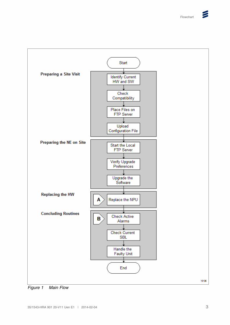
3 Flowchart
The flowchart in this section describes the flow of the tasks needed to completethe replacing of the hardware.
2 35/1543-HRA 901 20-V11 Uen E1 | 2014-02-04
Flowchart
Figure 1 Main Flow
335/1543-HRA 901 20-V11 Uen E1 | 2014-02-04
Replacing an NPU
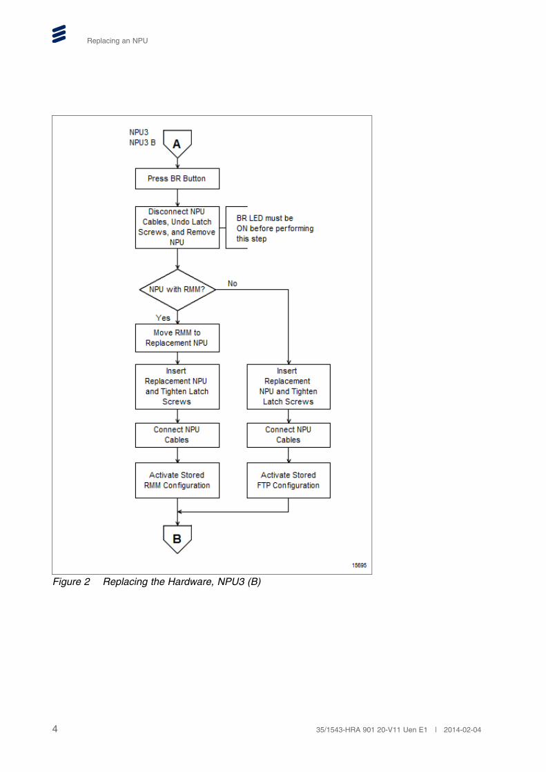
Figure 2 Replacing the Hardware, NPU3 (B)
4 35/1543-HRA 901 20-V11 Uen E1 | 2014-02-04
Flowchart
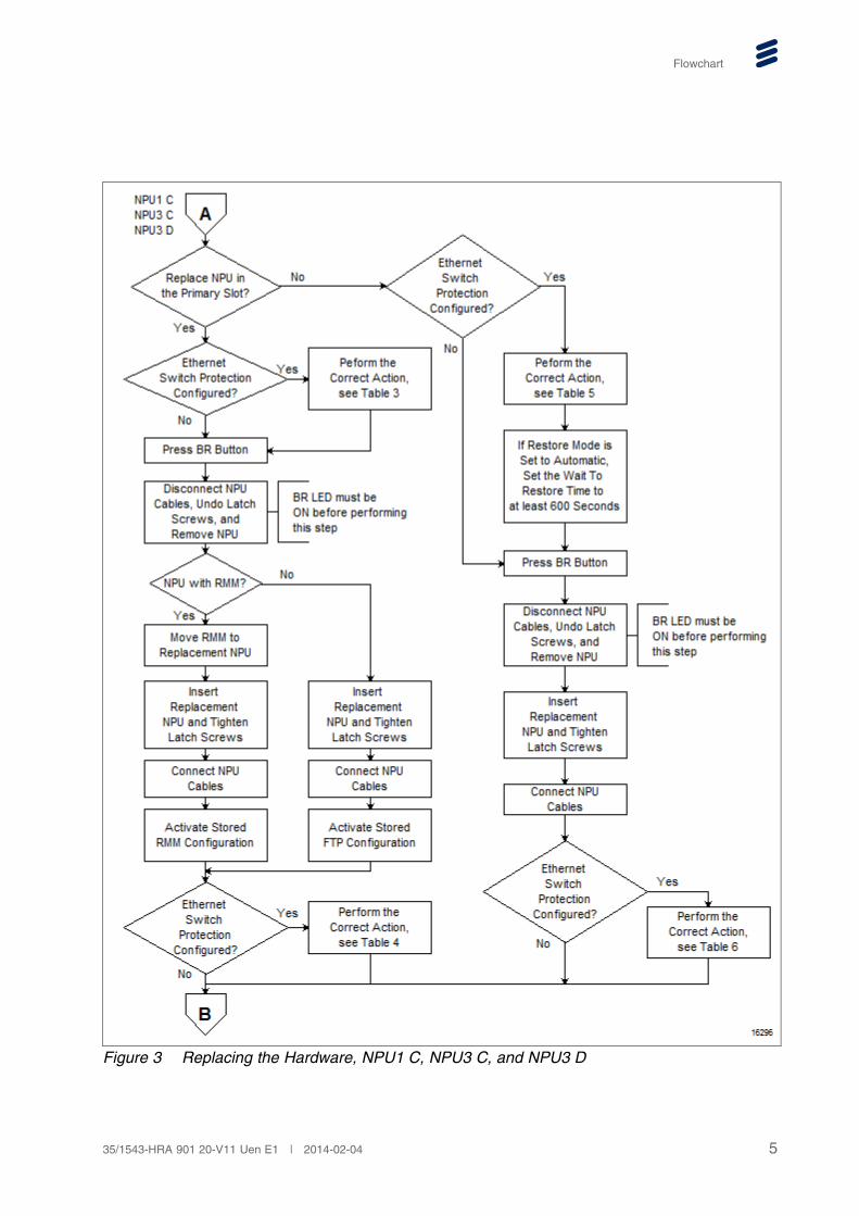
Figure 3 Replacing the Hardware, NPU1 C, NPU3 C, and NPU3 D
535/1543-HRA 901 20-V11 Uen E1 | 2014-02-04
Replacing an NPU
4 Replacing an NPU
4.1 Preparing a Site Visit
This section presents the preparations needed for a successful completion ofthe procedures in this instruction. All these preparations can be performed bothlocally and remotely.
4.1.1 Identifying Current Hardware and Software
To perform an inventory:
1. Access the NE and start MINI-LINK Craft by following the instructions inAccessing a Network Element, Reference [1].
2. In the Management Tree, right-click the NE.
3. Point to Tools, Software Upgrade and click Software Upgrade.
4. On the Software Upgrade page, confirm that the NE is running on theintended Software Baseline (SBL). Conforming Modules should be equalto yes. If Conforming Modules is equal to no, an upgrade is requiredlater on.
5. In the Management Tree, right-click the NE.
6. Point to Tools and click Inventory.
7. On the Inventory page. Identify the product numbers and R-states for theplug-in unit and its software.
4.1.2 Checking Compatibility
To check compatibility when replacing a unit:
1. For the replacement unit, follow the instructions in the compatibilitydocument in the Planning folder.
2. The replacement unit requires a minimum level of SBL on the NE. Checkcompatibility between the R-state of the replacement unit and the currentSBL running on the NE, see the compatibility document in the Planningfolder.
3. If a later SBL is required, select which SBL to be used.
4.1.3 Placing Files on an FTP Server
To place files on an FTP server:
6 35/1543-HRA 901 20-V11 Uen E1 | 2014-02-04
Replacing an NPU
1. If an upgrade of SBL is required, place the SBL files on a remote accessibleFTP server or a local FTP server by following the instructions in Upgradingor Downgrading a SW Baseline, Reference [16].
4.1.4 Uploading Configuration File
It is recommended to upload the existing configuration file and to generate aconfiguration report by following the instructions in Backing Up and Restoringa Configuration File, Reference [3] and Generating a Configuration Report,Reference [5].
When an NPU without RMM is replaced the configuration must be loaded froma configuration file, or entered by hand from a configuration report. When anNPU with RMM is replaced, the configuration file is uploaded to make sure thatbackup files are available in case the installation fails.
Note: If the existing NPU configuration has been changed, it is necessary towait at least 15 minutes before replacing the NPU to make sure thatthe new configuration is copied to the RMM.
4.2 Preparing the NE on Site
Follow the instructions in the following sections to prepare the NE on site.
4.2.1 Starting the Local FTP Server
To start the local FTP server:
1. Access the NE locally and start MINI-LINK Craft by following the instructionsin Accessing a Network Element, Reference [1].
2. On the Tools menu, click FTP Server.
3. On the FTP Server page, under Starting and Stopping, click Start tostart the FTP server.
4.2.2 Verifying the Software Upgrade Preferences
To verify the software upgrade preferences, perform the following steps:
1. In MINI-LINK Craft, in the Management Tree, right-click the NE.
2. Point to Tools , Software Upgrade and click Preferences.
3. On the Preferences page, make sure Version Control is enabled. IfVersion Control is disabled, it is recommended to perform an upgrade ofthe SBL to enable Version Control before replacing the HW. See Section4.2.3 on page 8 for more information on SBL upgrade. Version Controlcan be disabled manually but it cannot be enabled manually. An SBLupgrade is required to enable it.
735/1543-HRA 901 20-V11 Uen E1 | 2014-02-04
Replacing an NPU
Note: Version Control checks if load modules comply to the activeSBL. If necessary, load modules are automatically upgraded ordowngraded to comply with the active SBL.
4.2.3 Upgrading the Software
To upgrade the software, do as follows:
1. If an upgrade of SBL is required, upgrade the SBL by following theinstructions in Upgrading or Downgrading a SW Baseline, Reference [16].
Note: When replacing an NPU3 with an NPU3 B/C/D, the NE needs tobe upgraded to the desired SBL before the NPU is replaced. It isrecommended to upload the configuration file after upgrading the SBL,see Section 4.1.4 on page 7.
4.3 Replacing the Hardware
This section describes how to replace the hardware.
Note: Before performing the replacement, make sure that the requiredconfiguration file and SBL are placed on the FTP server, and the NE isupgraded to the required SBL with Version Control enabled.
Make sure the FTP server has been started as described in Section4.2.1 on page 7.
If RMM is available and the existing NE configuration has beenchanged, it is necessary to wait at least 15 minutes before replacingthe NPU to make sure that the new configuration is copied to the RMM.
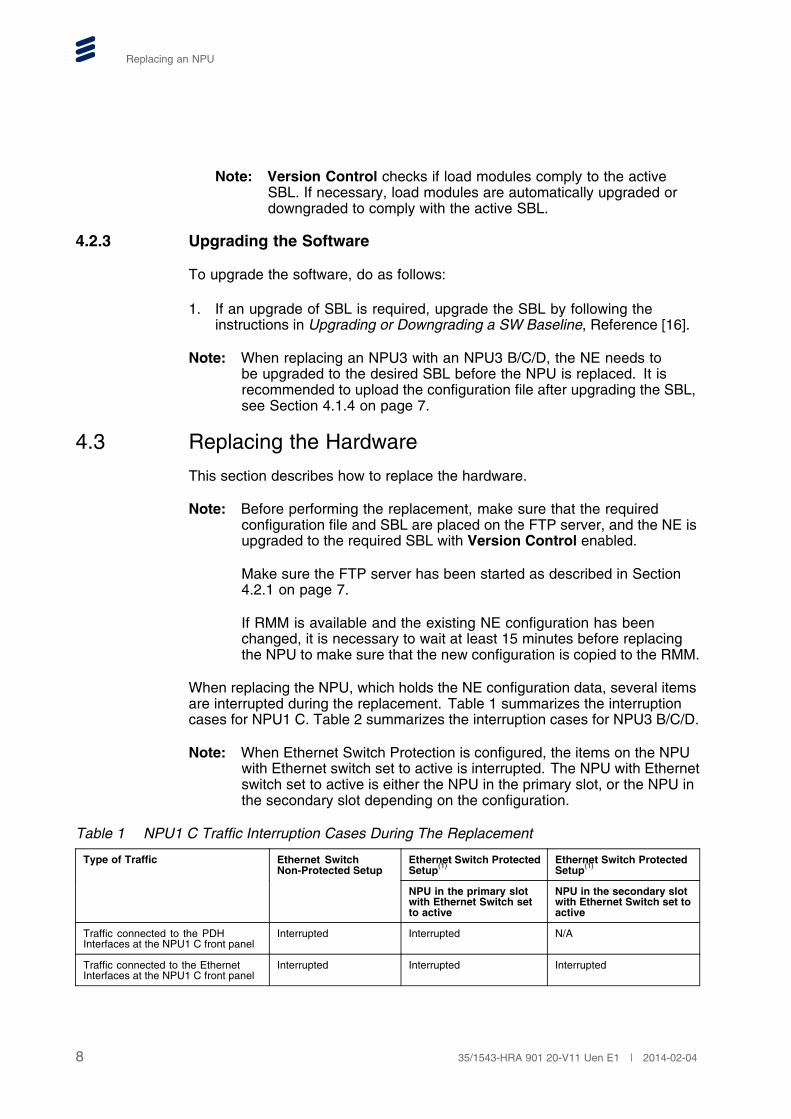
When replacing the NPU, which holds the NE configuration data, several itemsare interrupted during the replacement. Table 1 summarizes the interruptioncases for NPU1 C. Table 2 summarizes the interruption cases for NPU3 B/C/D.
Note: When Ethernet Switch Protection is configured, the items on the NPUwith Ethernet switch set to active is interrupted. The NPU with Ethernetswitch set to active is either the NPU in the primary slot, or the NPU inthe secondary slot depending on the configuration.
Table 1 NPU1 C Traffic Interruption Cases During The Replacement
Ethernet Switch ProtectedSetup(1)
Ethernet Switch ProtectedSetup(1)
Type of Traffic Ethernet SwitchNon-Protected Setup
NPU in the primary slotwith Ethernet Switch setto active
NPU in the secondary slotwith Ethernet Switch set toactive
Traffic connected to the PDHInterfaces at the NPU1 C front panel
Interrupted Interrupted N/A
Traffic connected to the EthernetInterfaces at the NPU1 C front panel
Interrupted Interrupted Interrupted
8 35/1543-HRA 901 20-V11 Uen E1 | 2014-02-04
Replacing an NPU
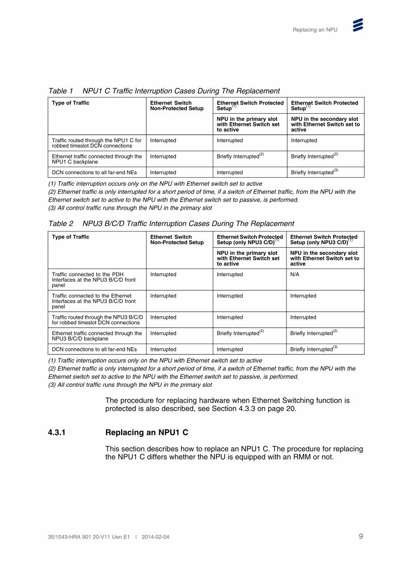
Table 1 NPU1 C Traffic Interruption Cases During The Replacement
Ethernet Switch ProtectedSetup(1)
Ethernet Switch ProtectedSetup(1)
Type of Traffic Ethernet SwitchNon-Protected Setup
NPU in the primary slotwith Ethernet Switch setto active
NPU in the secondary slotwith Ethernet Switch set toactive
Traffic routed through the NPU1 C forrobbed timeslot DCN connections
Interrupted Interrupted Interrupted
Ethernet traffic connected through theNPU1 C backplane
Interrupted Briefly Interrupted(2) Briefly Interrupted(2)
DCN connections to all far-end NEs Interrupted Interrupted Briefly Interrupted(3)
(1) Traffic interruption occurs only on the NPU with Ethernet switch set to active(2) Ethernet traffic is only interrupted for a short period of time, if a switch of Ethernet traffic, from the NPU with theEthernet switch set to active to the NPU with the Ethernet switch set to passive, is performed.(3) All control traffic runs through the NPU in the primary slot
Table 2 NPU3 B/C/D Traffic Interruption Cases During The Replacement
Ethernet Switch ProtectedSetup (only NPU3 C/D)(1)
Ethernet Switch ProtectedSetup (only NPU3 C/D)(1)
Type of Traffic Ethernet SwitchNon-Protected Setup
NPU in the primary slotwith Ethernet Switch setto active
NPU in the secondary slotwith Ethernet Switch set toactive
Traffic connected to the PDHInterfaces at the NPU3 B/C/D frontpanel
Interrupted Interrupted N/A
Traffic connected to the EthernetInterfaces at the NPU3 B/C/D frontpanel
Interrupted Interrupted Interrupted
Traffic routed through the NPU3 B/C/Dfor robbed timeslot DCN connections
Interrupted Interrupted Interrupted
Ethernet traffic connected through theNPU3 B/C/D backplane
Interrupted Briefly Interrupted(2) Briefly Interrupted(2)
DCN connections to all far-end NEs Interrupted Interrupted Briefly Interrupted(3)
(1) Traffic interruption occurs only on the NPU with Ethernet switch set to active(2) Ethernet traffic is only interrupted for a short period of time, if a switch of Ethernet traffic, from the NPU with theEthernet switch set to active to the NPU with the Ethernet switch set to passive, is performed.(3) All control traffic runs through the NPU in the primary slot
The procedure for replacing hardware when Ethernet Switching function isprotected is also described, see Section 4.3.3 on page 20.
4.3.1 Replacing an NPU1 C
This section describes how to replace an NPU1 C. The procedure for replacingthe NPU1 C differs whether the NPU is equipped with an RMM or not.
935/1543-HRA 901 20-V11 Uen E1 | 2014-02-04
Replacing an NPU
Note:
• To replace an NPU1 C in the primary slot with Ethernet SwitchProtection disabled, do one of the following:
� To replace an NPU1 C with RMM, follow the steps described inSection 4.3.1.1 on page 10.
� To replace an NPU1 C without RMM, follow the steps describedin Section 4.3.1.2 on page 12.
• To replace an NPU1 C in the primary slot with Ethernet SwitchProtection enabled, follow the steps described in Section 4.3.3.1on page 21.
• To replace an NPU1 C in the secondary slot with Ethernet SwitchProtection disabled, follow steps 3 to 10 in Section 4.3.3.2 on page22.
• To replace an NPU1 C in the secondary slot with Ethernet SwitchProtection enabled, follow the steps in Section 4.3.3.2 on page 22.
For more information about primary and secondary slots in the AMM, seeRecommendations for Positioning of Plug-in Units, Reference [11]
4.3.1.1 Replacing an NPU1 C with RMM
Caution!
Electrostatic Discharge (ESD) may damage the equipment. Always use anapproved ESD wrist strap to avoid damage to components fitted on printedcircuit boards.
When replacing the NPU1 C, which holds the NE configuration data, severalitems are interrupted during the replacement, see Table 1.
To replace an NPU1 C that is equipped with an RMM:
1. Press the BR button gently and release it. This is a request to take the unitOut of Service and all traffic related alarms will be disabled.
Note: The BR button must be pressed before the unit is removed, even ifthe Power (green) LED is OFF.
If the BR button is pressed, the unit will always perform a coldrestart after 90 seconds. When the unit performs a cold restart,several items are interrupted as described in Table 1.
10 35/1543-HRA 901 20-V11 Uen E1 | 2014-02-04
Replacing an NPU
6148b
PowerBR
OFF ON Flashing
LEDSymbols
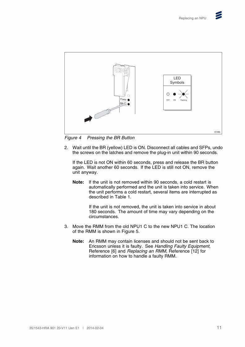
Figure 4 Pressing the BR Button
2. Wait until the BR (yellow) LED is ON. Disconnect all cables and SFPs, undothe screws on the latches and remove the plug-in unit within 90 seconds.
If the LED is not ON within 60 seconds, press and release the BR buttonagain. Wait another 60 seconds. If the LED is still not ON, remove theunit anyway.
Note: If the unit is not removed within 90 seconds, a cold restart isautomatically performed and the unit is taken into service. Whenthe unit performs a cold restart, several items are interrupted asdescribed in Table 1.
If the unit is not removed, the unit is taken into service in about180 seconds. The amount of time may vary depending on thecircumstances.
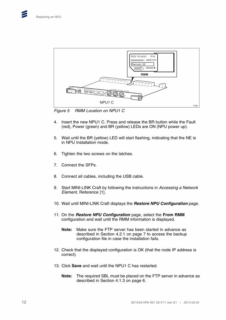
3. Move the RMM from the old NPU1 C to the new NPU1 C. The locationof the RMM is shown in Figure 5.
Note: An RMM may contain licenses and should not be sent back toEricsson unless it is faulty. See Handling Faulty Equipment,Reference [6] and Replacing an RMM, Reference [12] forinformation on how to handle a faulty RMM.
1135/1543-HRA 901 20-V11 Uen E1 | 2014-02-04
Replacing an NPU
ERICSSON
NPU1 C
TR2/LAN TR5 OUT TR5 IN OUT TR4 IN
O&M
TR:3A-3D TR:2A-2D User I/O:1A-1I
F PBR
NPU1 C11981
RMM
RYS 110 243/1 P1ABS80000001 20051101
Barcode 128
INSERT
Figure 5 RMM Location on NPU1 C
4. Insert the new NPU1 C. Press and release the BR button while the Fault(red), Power (green) and BR (yellow) LEDs are ON (NPU power up).
5. Wait until the BR (yellow) LED will start flashing, indicating that the NE isin NPU Installation mode.
6. Tighten the two screws on the latches.
7. Connect the SFPs.
8. Connect all cables, including the USB cable.
9. Start MINI-LINK Craft by following the instructions in Accessing a NetworkElement, Reference [1].
10. Wait until MINI-LINK Craft displays the Restore NPU Configuration page.
11. On the Restore NPU Configuration page, select the From RMMconfiguration and wait until the RMM information is displayed.
Note: Make sure the FTP server has been started in advance asdescribed in Section 4.2.1 on page 7 to access the backupconfiguration file in case the installation fails.
12. Check that the displayed configuration is OK (that the node IP address iscorrect).
13. Click Save and wait until the NPU1 C has restarted.
Note: The required SBL must be placed on the FTP server in advance asdescribed in Section 4.1.3 on page 6.
12 35/1543-HRA 901 20-V11 Uen E1 | 2014-02-04
Replacing an NPU
4.3.1.2 Replacing an NPU1 C without RMM
Caution!
Electrostatic Discharge (ESD) may damage the equipment. Always use anapproved ESD wrist strap to avoid damage to components fitted on printedcircuit boards.
When replacing the NPU1 C, which holds the NE configuration data, severalitems are interrupted during the replacement, see Table 1.
To replace an NPU1 C that is not equipped with an RMM:
1. Press the BR button gently and release it. This is a request to take the unitOut of Service and all traffic related alarms will be disabled.
Note: The BR button should be pressed before the unit is removed, evenif the Power (green) LED is OFF.
If the BR button is pressed, the unit will always perform a coldrestart after 90 seconds. When the unit performs a cold restart,several items are interrupted as described in Table 1.
6148b
PowerBR
OFF ON Flashing
LEDSymbols
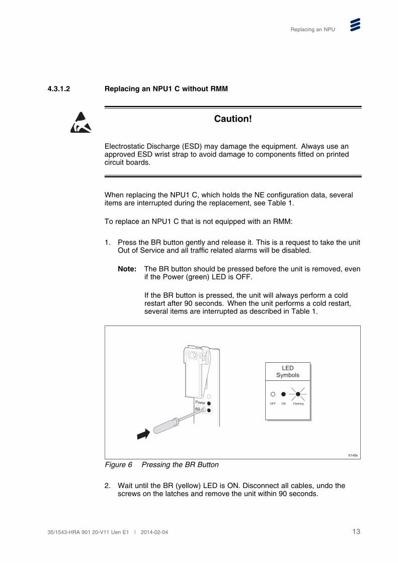
Figure 6 Pressing the BR Button
2. Wait until the BR (yellow) LED is ON. Disconnect all cables, undo thescrews on the latches and remove the unit within 90 seconds.
1335/1543-HRA 901 20-V11 Uen E1 | 2014-02-04
Replacing an NPU
If the LED is not ON within 60 seconds, press and release the BR buttonagain. Wait another 60 seconds. If the LED is still not ON, remove theunit anyway.
Note: If the unit is not removed within 90 seconds, a cold restart isautomatically performed and the unit is taken into service. Whenthe unit performs a cold restart, several items are interrupted asdescribed in Table 1.
If the unit is not removed, the unit is taken into service in about180 seconds. The amount of time may vary depending on thecircumstances.
3. Insert the new NPU1 C. Press and release the BR button while the Fault(red), Power (green) and BR (yellow) LEDs are ON (NPU power up).
4. Wait until the BR (yellow) LED will start flashing, indicating that the NE isin NPU Installation mode.
5. Tighten the two screws on the latches.
6. Connect the SFPs.
7. Connect all cables, including the USB cable.
8. Start MINI-LINK Craft by following the instructions in Accessing a NetworkElement, Reference [1].
9. Wait until MINI-LINK Craft displays the Restore NPU Configuration page.
10. On the Restore NPU Configuration page, under Configuration, selectFrom local ftp server 10.0.0.2 and wait until the FTP server informationis displayed.
11. Under Select File select the configuration file belonging to the old NPU1 C,and wait until configuration information is displayed.
Note: Make sure the FTP server has been started as described in Section4.2.1 on page 7.
12. Check that the displayed configuration is OK (that the node IP address iscorrect).
13. Click Save and wait until the NPU1 C has restarted.
Note: The required SBL must be placed on the FTP server in advance asdescribed in Section 4.1.3 on page 6.
4.3.2 Replacing an NPU3 B/C/D
This section describes how to replace an NPU3 B/C/D. The procedure forreplacing the NPU3 B/C/D differs whether the NPU is equipped with an RMM ornot.
14 35/1543-HRA 901 20-V11 Uen E1 | 2014-02-04
Replacing an NPU
Note:
• To replace an NPU3 B/C/D in the primary slot with Ethernet SwitchProtection disabled, do one of the following:
� To replace an NPU3 B/C/D with RMM, follow the stepsdescribed in Section 4.3.2.1 on page 15.
� To replace an NPU3 B/C/D without RMM, follow the stepsdescribed in Section 4.3.2.2 on page 18.
• To replace an NPU3 C/D in the primary slot with Ethernet SwitchProtection enabled, follow the steps described in Section 4.3.3.1on page 21.
• To replace an NPU3 C/D in the secondary slot with Ethernet SwitchProtection disabled, follow steps 3 to 10 in Section 4.3.3.2 on page22.
• To replace an NPU3 C/D in the secondary slot with Ethernet SwitchProtection enabled, follow the steps in Section 4.3.3.2 on page 22.
For more information about primary and secondary slots in the AMM, seeRecommendations for Positioning of Plug-in Units, Reference [11]
NPU3 C/D has support for synchronous Ethernet which is not the case forNPU3 B.
4.3.2.1 Replacing an NPU3 B/C/D with RMM
Caution!
Electrostatic Discharge (ESD) may damage the equipment. Always use anapproved ESD wrist strap to avoid damage to components fitted on printedcircuit boards.
When replacing the NPU3 B/C/D, which holds the NE configuration data,several items are interrupted during the replacement, see Table 2.
Note: ServiceOn Element Manager will show the old NPU3 B/C/D until a newhardware scan is performed towards the node. The hardware scan isperformed schematically.
To replace the NPU3 B/C/D with RMM:
1535/1543-HRA 901 20-V11 Uen E1 | 2014-02-04
Replacing an NPU
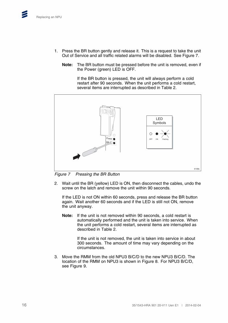
1. Press the BR button gently and release it. This is a request to take the unitOut of Service and all traffic related alarms will be disabled. See Figure 7.
Note: The BR button must be pressed before the unit is removed, even ifthe Power (green) LED is OFF.
If the BR button is pressed, the unit will always perform a coldrestart after 90 seconds. When the unit performs a cold restart,several items are interrupted as described in Table 2.
6148b
PowerBR
OFF ON Flashing
LEDSymbols
Figure 7 Pressing the BR Button
2. Wait until the BR (yellow) LED is ON, then disconnect the cables, undo thescrew on the latch and remove the unit within 90 seconds.
If the LED is not ON within 60 seconds, press and release the BR buttonagain. Wait another 60 seconds and if the LED is still not ON, removethe unit anyway.
Note: If the unit is not removed within 90 seconds, a cold restart isautomatically performed and the unit is taken into service. Whenthe unit performs a cold restart, several items are interrupted asdescribed in Table 2.
If the unit is not removed, the unit is taken into service in about300 seconds. The amount of time may vary depending on thecircumstances.
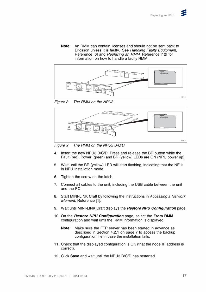
3. Move the RMM from the old NPU3 B/C/D to the new NPU3 B/C/D. Thelocation of the RMM on NPU3 is shown in Figure 8. For NPU3 B/C/D,see Figure 9.
16 35/1543-HRA 901 20-V11 Uen E1 | 2014-02-04
Replacing an NPU
Note: An RMM can contain licenses and should not be sent back toEricsson unless it is faulty. See Handling Faulty Equipment,Reference [6] and Replacing an RMM, Reference [12] forinformation on how to handle a faulty RMM.
NPU3
TR:4A-4D/User Out:E-F
10/100 Base-TF P
O&M
E1/DS1 10/100 Base-T
LANTR:3
10018
Figure 8 The RMM on the NPU3
NPU3 B E1/DS110/100/1000BASE-T 10/100/1000BASE-T
TR:2/LANTR:3
TR:4A-4D/User Out:E-F
O&M
F P
11615
Figure 9 The RMM on the NPU3 B/C/D
4. Insert the new NPU3 B/C/D. Press and release the BR button while theFault (red), Power (green) and BR (yellow) LEDs are ON (NPU power up).
5. Wait until the BR (yellow) LED will start flashing, indicating that the NE isin NPU Installation mode.
6. Tighten the screw on the latch.
7. Connect all cables to the unit, including the USB cable between the unitand the PC.
8. Start MINI-LINK Craft by following the instructions in Accessing a NetworkElement, Reference [1].
9. Wait until MINI-LINK Craft displays the Restore NPU Configuration page.
10. On the Restore NPU Configuration page, select the From RMMconfiguration and wait until the RMM information is displayed.
Note: Make sure the FTP server has been started in advance asdescribed in Section 4.2.1 on page 7 to access the backupconfiguration file in case the installation fails.
11. Check that the displayed configuration is OK (that the node IP address iscorrect).
12. Click Save and wait until the NPU3 B/C/D has restarted.
1735/1543-HRA 901 20-V11 Uen E1 | 2014-02-04
Replacing an NPU
Note: The required SBL must be placed on the FTP server in advance asdescribed in Section 4.1.3 on page 6.
4.3.2.2 Replacing an NPU3 B/C/D without RMM
Caution!
Electrostatic Discharge (ESD) may damage the equipment. Always use anapproved ESD wrist strap to avoid damage to components fitted on printedcircuit boards.
When replacing the NPU3 B/C/D, which holds the NE configuration data,several items are interrupted during the replacement, see Table 2.
Note: ServiceOn Element Manager will show the old NPU3 B/C/D until a newhardware scan is performed towards the node. The hardware scan isperformed schematically.
To replace an NPU3 B/C/D that is not equipped with an RMM:
1. Press the BR button gently and release it. This is a request to take the unitOut of Service and all traffic related alarms will be disabled.
Note: The BR button should be pressed before the unit is removed, evenif the Power (green) LED is OFF.
If the BR button is pressed, the unit will always perform a coldrestart after 90 seconds. When the unit performs a cold restart,several items are interrupted as described in Table 2.
18 35/1543-HRA 901 20-V11 Uen E1 | 2014-02-04
Replacing an NPU
6148b
PowerBR
OFF ON Flashing
LEDSymbols
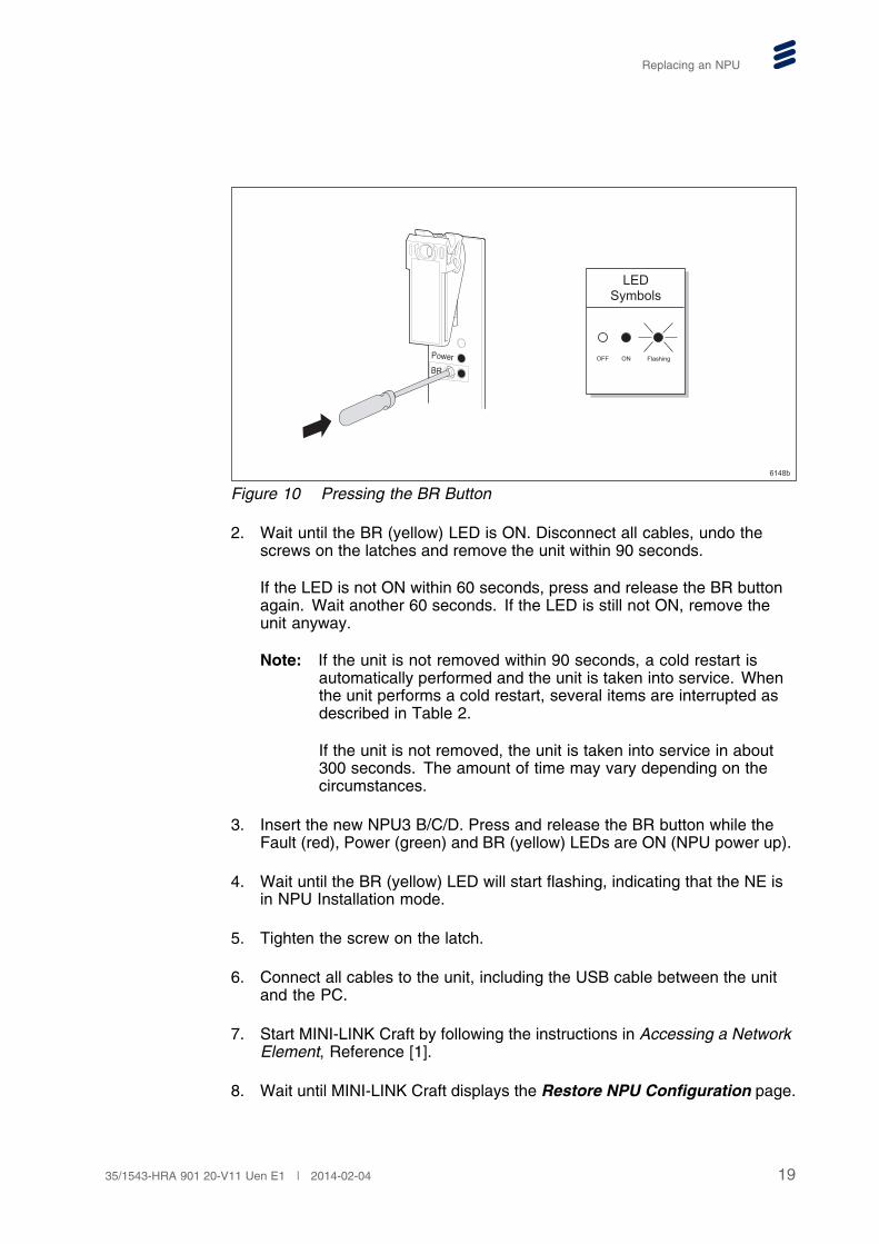
Figure 10 Pressing the BR Button
2. Wait until the BR (yellow) LED is ON. Disconnect all cables, undo thescrews on the latches and remove the unit within 90 seconds.
If the LED is not ON within 60 seconds, press and release the BR buttonagain. Wait another 60 seconds. If the LED is still not ON, remove theunit anyway.
Note: If the unit is not removed within 90 seconds, a cold restart isautomatically performed and the unit is taken into service. Whenthe unit performs a cold restart, several items are interrupted asdescribed in Table 2.
If the unit is not removed, the unit is taken into service in about300 seconds. The amount of time may vary depending on thecircumstances.
3. Insert the new NPU3 B/C/D. Press and release the BR button while theFault (red), Power (green) and BR (yellow) LEDs are ON (NPU power up).
4. Wait until the BR (yellow) LED will start flashing, indicating that the NE isin NPU Installation mode.
5. Tighten the screw on the latch.
6. Connect all cables to the unit, including the USB cable between the unitand the PC.
7. Start MINI-LINK Craft by following the instructions in Accessing a NetworkElement, Reference [1].
8. Wait until MINI-LINK Craft displays the Restore NPU Configuration page.
1935/1543-HRA 901 20-V11 Uen E1 | 2014-02-04
Replacing an NPU
9. On the Restore NPU Configuration page, under Configuration, selectFrom local ftp server 10.0.0.2 and wait until the FTP server informationis displayed.
10. Under Select File select the configuration file belonging to the old NPU3B/C/D, and wait until configuration information is displayed.
Note: Make sure the FTP server has been started as described in Section4.2.1 on page 7.
11. Check that the displayed configuration is OK (that the node IP address iscorrect).
12. Click Save and wait until the NPU3 B/C/D has restarted.
Note: The required SBL must be placed on the FTP server in advance asdescribed in Section 4.1.3 on page 6.
4.3.3 Replacing an NPU with Ethernet Switch Protection Configured
The following sections describe how to replace an NPU1 C, NPU3 C, or NPU3D when Ethernet Switch Protection is configured. For more information aboutEthernet Switch Protection, refer to Configuring Ethernet Switch Protection,Reference [4]. For more information about primary and secondary slots in theAMM, see Recommendations for Positioning of Plug-in Units, Reference [11].
Note: In this section, the NPU with the Ethernet switch set to active is referredto as the active NPU. The NPU with the Ethernet switch set to passive,is referred to as the passive NPU.
If the current NPU that is replaced is the active NPU, several items areinterrupted during the replacement of the NPU as described in Table 1 forNPU1 C, and Table 2 for NPU3 C/D.
Note: Ethernet traffic is only interrupted for a short period of time, if a switch ofEthernet traffic, from the active NPU to the passive NPU, is performed.
For NPU3 C/D, ServiceOn Element Manager will show the old NPUuntil a new hardware scan is performed towards the node. Thehardware scan is performed schematically.
Before replacing the NPU, make sure to consider the following:
• If the NPU in the secondary slot is replaced, make sure that the new NPUhas a SW version R5 or newer. The MINI-LINK TN will not boot up inany other case. For information about SW versions, see Section 4.1.1on page 6.
• If the NPU in the primary slot is replaced, it is highly recommended thatthe new NPU has a SW version R5 or newer. This is to minimize trafficdowntime. For information about SW versions, see Section 4.1.1 on page 6.
20 35/1543-HRA 901 20-V11 Uen E1 | 2014-02-04
Replacing an NPU
• If the NPU in the primary slot is being replaced, make sure not to use itin another MINI-LINK TN before a new NPU is installed in the currentMINI-LINK TN. This is to avoid problems with duplicate bridge MACaddresses.
• If the MINI-LINK TN restarts due to a power failure with an NPU installedonly in the secondary slot, the MINI-LINK TN will not reboot until an NPU inthe primary slot is installed. For more information, see Configuring EthernetSwitch Protection, Reference [4].
Note: If the NPU in the primary slot is replaced and Spanning Tree Protocol(STP) is configured, the Ethernet traffic is interrupted for a few seconds.This interruption is because the new NPU in the primary slot has adifferent MAC address, which leads to a change of bridge ID.
To replace the NPU with Ethernet Switch Protection Configured, perform thefollowing:
• To replace the NPU in the primary slot, see Section 4.3.3.1 on page 21.
• To replace the NPU in the secondary slot, see Section 4.3.3.2 on page 22.
4.3.3.1 Replacing an NPU in the Primary Slot
Perform the following to replace the NPU in the primary slot:
Note: In this section, the NPU with the Ethernet switch set to active is referredto as the active NPU. The NPU with the Ethernet switch set to passive,is referred to as the passive NPU.
1. Depending on the configuration of the NPU in the primary slot, perform thecorrect action according to Table 3.
Table 3 Correct Action to Perform before replacing an NPU in the primary slot
Ethernet Switch statuson the NPU in theprimary slot
Protection mode Action to perform
Active Auto No action is required.
The NPU in thesecondary slotautomatically becomesthe active NPU duringthe replacement of theNPU in the primary slot.
2135/1543-HRA 901 20-V11 Uen E1 | 2014-02-04
Replacing an NPU
Ethernet Switch statuson the NPU in theprimary slot
Protection mode Action to perform
Active Manual Set the NPU in thesecondary slot toactive. For moreinformation, seeConfiguring EthernetSwitch Protection,Reference [4].
Passive – No action is required.
2. Do one of the following:
• For NPU1 C with RMM, follow the steps in Section 4.3.1.1 on page 10.
• For NPU1 C without RMM, follow the steps in Section 4.3.1.2 on page12.
• For NPU3 C/D with RMM, follow the steps in Section 4.3.2.1 on page15.
• For NPU3 C/D without RMM, follow the steps in Section 4.3.2.2 onpage 18.
3. Depending on the configuration scenario at the time of replacement of theNPU, perform the correct action according to Table 4.
Table 4 Correct Action to Perform after replacing the NPU in the primary slot
ReplacedNPU slot(1)
RestoreMode
ProtectionMode
Action to perform
Primary – Auto No further action is required.
When the new NPU hasrestarted, Ethernet SwitchProtection is enabled and theNPU in the secondary slot isactive.
Primary – Manual The NPU in the secondaryslot is the active NPU afterreplacement of the NPU in theprimary slot.
To manually set the NPU inthe primary slot to active, seeConfiguring Ethernet SwitchProtection, Reference [4].
(1) For more information about primary and secondary slots, see Recommendations forPositioning of Plug-in Units, Reference [11]
22 35/1543-HRA 901 20-V11 Uen E1 | 2014-02-04
Replacing an NPU
4.3.3.2 Replacing an NPU in the Secondary Slot
Perform the following to replace an NPU in the secondary slot:
Note: In this section, the NPU with the Ethernet switch set to active is referredto as the active NPU. The NPU with the Ethernet switch set to passive,is referred to as the passive NPU.
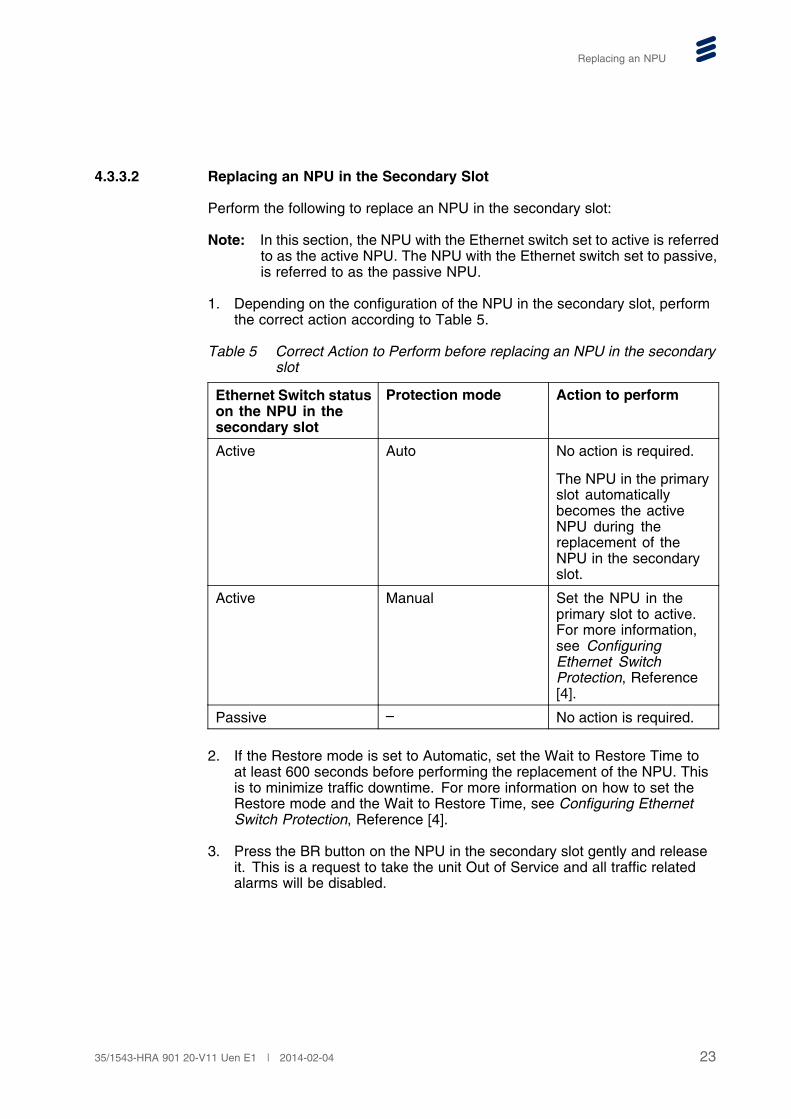
1. Depending on the configuration of the NPU in the secondary slot, performthe correct action according to Table 5.
Table 5 Correct Action to Perform before replacing an NPU in the secondaryslot
Ethernet Switch statuson the NPU in thesecondary slot
Protection mode Action to perform
Active Auto No action is required.
The NPU in the primaryslot automaticallybecomes the activeNPU during thereplacement of theNPU in the secondaryslot.
Active Manual Set the NPU in theprimary slot to active.For more information,see ConfiguringEthernet SwitchProtection, Reference[4].
Passive – No action is required.
2. If the Restore mode is set to Automatic, set the Wait to Restore Time toat least 600 seconds before performing the replacement of the NPU. Thisis to minimize traffic downtime. For more information on how to set theRestore mode and the Wait to Restore Time, see Configuring EthernetSwitch Protection, Reference [4].
3. Press the BR button on the NPU in the secondary slot gently and releaseit. This is a request to take the unit Out of Service and all traffic relatedalarms will be disabled.
2335/1543-HRA 901 20-V11 Uen E1 | 2014-02-04
Replacing an NPU
6148b
PowerBR
OFF ON Flashing
LEDSymbols
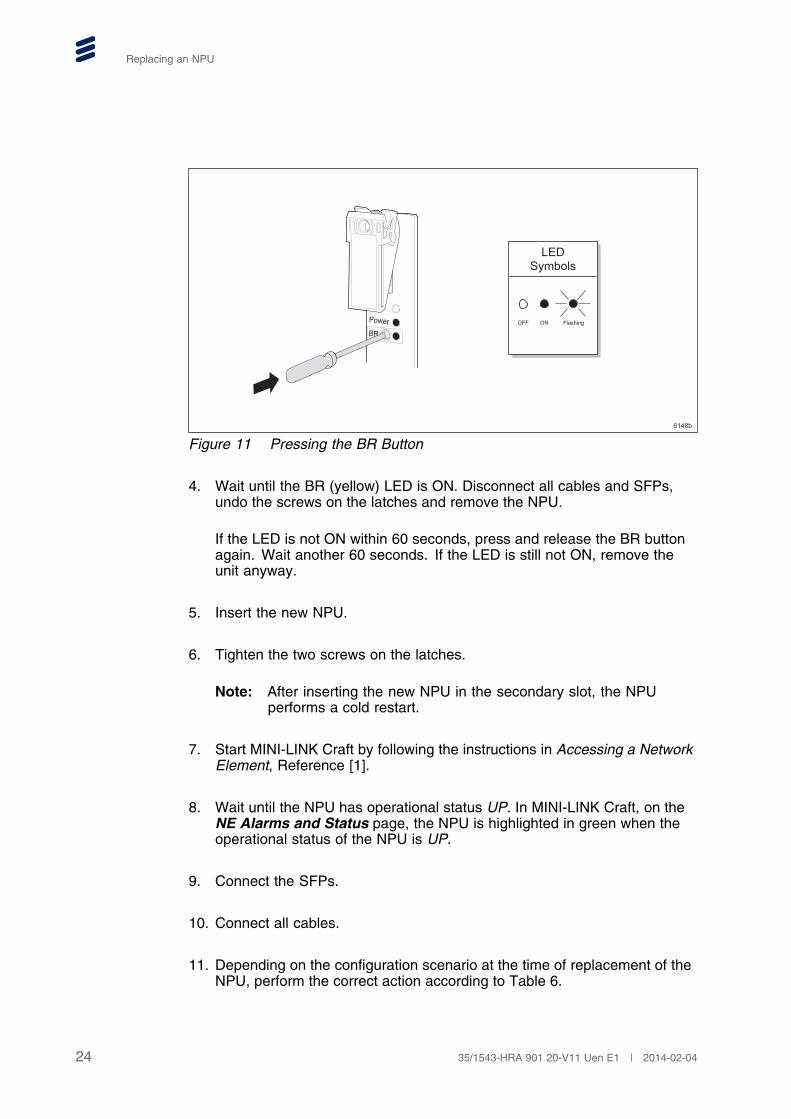
Figure 11 Pressing the BR Button
4. Wait until the BR (yellow) LED is ON. Disconnect all cables and SFPs,undo the screws on the latches and remove the NPU.
If the LED is not ON within 60 seconds, press and release the BR buttonagain. Wait another 60 seconds. If the LED is still not ON, remove theunit anyway.
5. Insert the new NPU.
6. Tighten the two screws on the latches.
Note: After inserting the new NPU in the secondary slot, the NPUperforms a cold restart.
7. Start MINI-LINK Craft by following the instructions in Accessing a NetworkElement, Reference [1].
8. Wait until the NPU has operational status UP. In MINI-LINK Craft, on theNE Alarms and Status page, the NPU is highlighted in green when theoperational status of the NPU is UP.
9. Connect the SFPs.
10. Connect all cables.
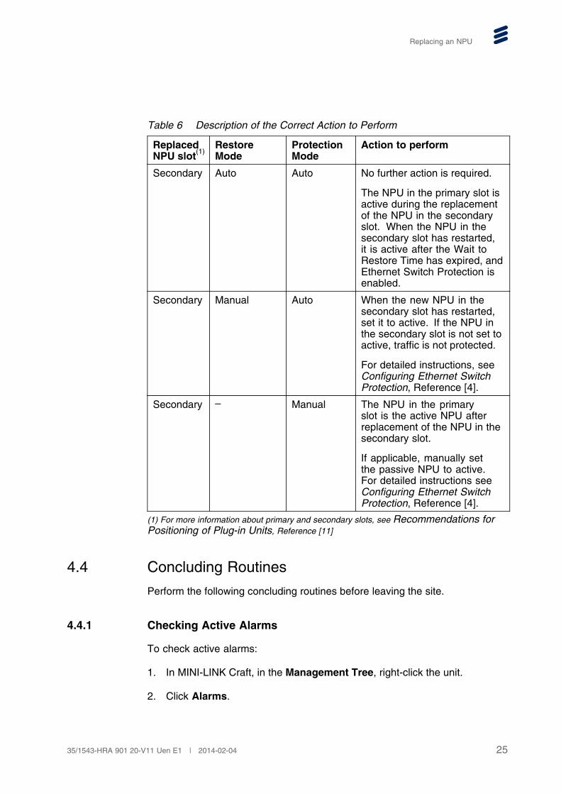
11. Depending on the configuration scenario at the time of replacement of theNPU, perform the correct action according to Table 6.
24 35/1543-HRA 901 20-V11 Uen E1 | 2014-02-04
Replacing an NPU
Table 6 Description of the Correct Action to Perform
ReplacedNPU slot(1)
RestoreMode
ProtectionMode
Action to perform
Secondary Auto Auto No further action is required.
The NPU in the primary slot isactive during the replacementof the NPU in the secondaryslot. When the NPU in thesecondary slot has restarted,it is active after the Wait toRestore Time has expired, andEthernet Switch Protection isenabled.
Secondary Manual Auto When the new NPU in thesecondary slot has restarted,set it to active. If the NPU inthe secondary slot is not set toactive, traffic is not protected.
For detailed instructions, seeConfiguring Ethernet SwitchProtection, Reference [4].
Secondary – Manual The NPU in the primaryslot is the active NPU afterreplacement of the NPU in thesecondary slot.
If applicable, manually setthe passive NPU to active.For detailed instructions seeConfiguring Ethernet SwitchProtection, Reference [4].
(1) For more information about primary and secondary slots, see Recommendations forPositioning of Plug-in Units, Reference [11]
4.4 Concluding Routines
Perform the following concluding routines before leaving the site.
4.4.1 Checking Active Alarms
To check active alarms:
1. In MINI-LINK Craft, in the Management Tree, right-click the unit.
2. Click Alarms.
2535/1543-HRA 901 20-V11 Uen E1 | 2014-02-04
Replacing an NPU
3. If alarms are active on the Alarms and Status page of the unit, performcorrective actions for each active alarm as described in Alarm Descriptions,Reference [2].
4.4.2 Checking Current SBL
To check Software Baseline (SBL):
1. In MINI-LINK Craft, in the Management Tree, right-click the NE.
2. Point to Tools, Software Upgrade and click Software Upgrade.
3. On the Software Upgrade page, identify the current SBL running on theNE.
4. If the current SBL is not the desired SBL, upgrade the SBL by following theinstructions in Upgrading or Downgrading a SW Baseline, Reference [16].
4.4.3 Handling Faulty Units
If the old unit was faulty, follow the instructions in Handling Faulty Equipment, Reference [6].
26 35/1543-HRA 901 20-V11 Uen E1 | 2014-02-04
Reference List
Reference List
[1] Accessing a Network Element, 3/1543-HRA 901 20-V11
[2] Alarm Descriptions, 5/1543-HRA 901 20-V11
[3] Backing Up and Restoring a Configuration File, 80/1543-HRA 901 20-V11
[4] Configuring Ethernet Switch Protection, 62/1543-HRA 901 20-V11
[5] Generating a Configuration File, 81/1543-HRA 901 20-V11
[6] Handling Faulty Equipment, 1/1541-HRA 901 20-V11
[7] HW Management Overview, 5/1551-HRA 901 20-V11
[8] Installing Indoor Equipment, 1531-HRA 901 20-V11
[9] MINI-LINK Craft User Interface Descriptions, 7/1551-HRA 901 20-V11
[10] Personal Health and Safety Information, 124 46-2885
[11] Recommendations for Positioning of Plug-in Units , 8/1543-HRA 90120-V11
[12] Replacing an RMM, 36/1543-HRA 901 20-V11
[13] Security Management Operations , 8/1543-HRA 901 20-V11
[14] Supplementary Safety Information for MINI-LINK, 124 46-HSD 101 16/1
[15] System Safety Information, 124 46-2886
[16] Upgrading or Downgrading a SW Baseline, 12/1543-HRA 901 20-V11
2735/1543-HRA 901 20-V11 Uen E1 | 2014-02-04