repair parts manual - snorkellifts.com · 47 301405 1 brakepin,righthand 48 301407 4...
TRANSCRIPT

Repair PartsManual
P/N 0360525
February 1998 - revised December 2001
battery powered
electric
Manufactured 01-97 through 12-00

General information
© Snorkel – all rights reserved Printed in USA
DANGER
CAUTION
About this manual:
This repair parts manual covers current production ma-
chines only.
While Snorkel has attempted in every way to confirm
that all information in this manual is correct, improve-
ments are being constantly made to the machine that
may not be reflected in this manual.
If you find information in this manual that is not correct,
or is confusing, you are urged to report your findings to
Snorkel for our evaluation.
Your input is important to us and will be used in future
printings of this manual.
Every person who repairs this machine must be quali-
fied and authorized to do so.
DO NOT modify this aerial platform without prior
written consent of Snorkel Engineering Depart-
ment. Modification may void the warranty,adversely
affect stability, or affect the operational characteris-
tics of the aerial platform.
This machine is covered by a limited warranty that spe-
cifically identifies items warrantied by Snorkel and those
items covered by original manufacturers warranty.
A copy of the Snorkel Limited Warranty is located on the
inside of the back cover of this manual.
All correspondence relative to this machine, such as
field reports, discrepancy reports, requests for informa-
tion, etc., should be directed to:
Snorkel International, Inc.
P.O. Box 1160
St. Joseph, MO 64502-1160 USA
Phone: (816)-364-0317
http://www.snorkelusa.com
Abbreviations
The following abbreviations may be used in this manual:
AC. . . . . . . . . . . . . . . . . . . . . . . . .alternating current
ANSI . . . . . . . American National Standards Institute
CCA. . . . . . . . . . . . . . . . . . . . . . . cold cranking amps
cm. . . . . . . . . . . . . . . . . . . . . . . . . . . . . . .centimeter
DC. . . . . . . . . . . . . . . . . . . . . . . . . . . . .direct current
EMS . . . . . . . . . . . . . envelope management system
GFCI . . . . . . . . . . . . . . . . ground fault circuit interrupt
LP . . . . . . . . . . . . . . . . . . . . . . . . . liquified petroleum
LPG . . . . . . . . . . . . . . . . . . . . liquified petroleum gas
mm . . . . . . . . . . . . . . . . . . . . . . . . . . . . . .millimeters
ft . . . . . . . . . . . . . . . . . . . . . . . . . . . . . . . . . . . . .feet
in . . . . . . . . . . . . . . . . . . . . . . . . . . . . . . . . . . . . .inch
lbs . . . . . . . . . . . . . . . . . . . . . . . . . . . . . . . . .pounds
no . . . . . . . . . . . . . . . . . . . . . . . . . . . . . . . . .number
NPT . . . . . . . . . . . . . . . . . . . . . . national pipe thread
psi . . . . . . . . . . . . . . . . . . . . . pounds per square inch
qty . . . . . . . . . . . . . . . . . . . . . . . . . . . . . . . . .quantity
UL . . . . . . . . . . . . . . . Underwriters Laboratories Inc.
Electrical Hazard
The aerial platform is not electrically insulated.
Death or serious injury can result from contact with,
or inadequate clearance from, an energized
conductor.
Do not go closer than the minimum safe approach
distance as defined by the minimum Safe Approach
Distance as defined by ANSI Standards.
Regard all conductors as energized.
Allow for electrical wire sag and aerial platform sway.
If the work platform, or any part of the aerial platform
contacts a high-voltage electrical conductor, the entire
machine can become electrically charged.
If that happens, remain on the machine and do not con-
tact any other structure or object. This includes the
ground, adjacent buildings, poles, and any other objects
that are not part of the aerial platform.
Such contact could make your body a conductor to the
other object, creating an electrical shock hazard result-
ing in death or serious injury.
If an aerial platform is in contact with an energized con-
ductor the platform operator must warn ground person-
nel in the vicinity to stay away. Their bodies can conduct
electricity creating an electrical shock hazard resulting
in death or serious injury.
Do not approach or leave the aerial platform until the
electricity has been turned off.
Do not attempt to operate the lower controls when the
work platform or any part of the aerial platform is in con-
tact with a high-voltage electrical conductor or if there is
an immediate danger of such contact.
Personnel on or near an aerial platform must be continu-
ously aware of electrical hazards, recognizing that
death or serious injury can result from contact with an
energized conductor.

SL 19 – 01-97 through 01-01
Table of Contents
Service and parts information
To order service or repair parts . . . . . . . . . . . . . . . . . . i
ANSI and OSHA compliance. . . . . . . . . . . . . . . . . . . . i
Manuals . . . . . . . . . . . . . . . . . . . . . . . . . . . . . . . . . . .i
Parts order form . . . . . . . . . . . . . . . . . . . . . . . . . . . . . ii
Section 1. - Repair parts
Base frame . . . . . . . . . . . . . . . . . . . . . . . . . . . . . . .1-2
Bearing hub . . . . . . . . . . . . . . . . . . . . . . . . . . . . . . .1-9
Hydraulic tray. . . . . . . . . . . . . . . . . . . . . . . . . . . . .1-10
Battery tray . . . . . . . . . . . . . . . . . . . . . . . . . . . . . .1-14
Scissor arm mounting . . . . . . . . . . . . . . . . . . . . . . 1-16
Scissor arm stack . . . . . . . . . . . . . . . . . . . . . . . . .1-19
Platform . . . . . . . . . . . . . . . . . . . . . . . . . . . . . . . . .1-20
Placards and decals . . . . . . . . . . . . . . . . . . . . . . . 1-23
Covers . . . . . . . . . . . . . . . . . . . . . . . . . . . . . . . . . .1-24
Section 2. - Hydraulics
Control valve, main . . . . . . . . . . . . . . . . . . . . . . . . .2-2
Manifold valve . . . . . . . . . . . . . . . . . . . . . . . . . . . . .2-4
Cylinder, brake - Green . . . . . . . . . . . . . . . . . . . . . . 2-6
Cylinder, brake - Prince. . . . . . . . . . . . . . . . . . . . . . 2-7
Cylinder, brake - Rosenboom . . . . . . . . . . . . . . . . . 2-8
Cylinder, cushion - Green . . . . . . . . . . . . . . . . . . . . 2-9
Cylinder, lift - GBI . . . . . . . . . . . . . . . . . . . . . . . . .2-10
Cylinder, lift - Green . . . . . . . . . . . . . . . . . . . . . . . 2-11
Cylinder, steering - Green . . . . . . . . . . . . . . . . . . . 2-12
Lift cylinder cartridge valve . . . . . . . . . . . . . . . . . . 2-13
Hydraulic drive motor - Parker. . . . . . . . . . . . . . . . 2-14
Hydraulic drive motor - White . . . . . . . . . . . . . . . . 2-16
Section 3. - Electrical
Lower control box before 3-1-99 . . . . . . . . . . . . . . . 3-2
Lower control box after 3-1-99 . . . . . . . . . . . . . . . . 3-5
Upper control box before 12-6-99 . . . . . . . . . . . . . . 3-6
Upper control box after 12-6-99 . . . . . . . . . . . . . . . 3-9
Battery charger . . . . . . . . . . . . . . . . . . . . . . . . . . .3-10
Controller, upper control box . . . . . . . . . . . . . . . . . 3-11
DC electric motor, Leeson. . . . . . . . . . . . . . . . . . . 3-12
DC electric motor, Ohio . . . . . . . . . . . . . . . . . . . . . 3-13
Platform control cable . . . . . . . . . . . . . . . . . . . . . . 3-14
Proximity switch. . . . . . . . . . . . . . . . . . . . . . . . . . .3-15
Wire harness, main . . . . . . . . . . . . . . . . . . . . . . . .3-16
Section 4. - Factory installed options
AC outlet on platform, GFCI . . . . . . . . . . . . . . . . . . 4-2
Battery condition indicator. . . . . . . . . . . . . . . . . . . . 4-4
Dual lanyard attachment . . . . . . . . . . . . . . . . . . . . . 4-5
Flashing light . . . . . . . . . . . . . . . . . . . . . . . . . . . . . .4-6
Key switch . . . . . . . . . . . . . . . . . . . . . . . . . . . . . . . .4-7
Operator horn . . . . . . . . . . . . . . . . . . . . . . . . . . . . .4-8
Platform entry gate, automatic closing . . . . . . . . . . 4-9


Service and parts information
To order service or repair parts
When placing an order for service or repair parts, please
have the following information available for your ma-
chine.
�Machine model number
�Machine serial number
� Snorkel part number
� Description of part
� Quantity of parts required
� Your purchase order number
� Address for order to “Ship To”
� Your desired shipment method
The parts order form on the following page may be
mailed or faxed to the attention of Parts Worldwide at the
following location:
Snorkel International, Inc.
P.O. Box 1160
St. Joseph, MO 64502-1160 USA
Phone: 1-(800)-255-0317
Parts Worldwide Fax: (816)-364-6312
Attention: Parts Department
For your convenience, our electronic on-line ordering
system is available at the following Internet location:
http://www.omniquip.com
ANSI and OSHA compliance
All owners and users of the aerial platform must read,
understand, and comply with all applicable regulations.
Ultimate compliance to OSHA regulations is the respon-
sibility of the user and their employer.
ANSI publications clearly identify the responsibilities of
all personnel who may be involved with the aerial plat-
form. A reprint of the “Manual of Responsibilities for
Dealers, Owners, Users, Operators, Lessors and Les-
sees of ANSI/SIA A92.5-1992 Boom-Supported Ele-
vating Work Platforms” is available from Snorkel dealers
or from the factory upon request.
Copies are also available from:
Scaffold Industry Association
20335 Ventura Blvd. Suite 310
Woodland Hills, CA 91364-2471 USA
Manuals
Manuals are available from Snorkel to support any of the
machines that we produce.
The specific manuals for SL 19 are as follows:
� Operator’s Manual
Snorkel part number - 0360524
� Repair Parts Manual
Snorkel part number - 0360525
� Troubleshooting Guide
Snorkel part number - 302988
� ANSI Manual of Responsibilities
ANSI/SIA A92.6-1990
SL 19 – 01-97 through 01-01 i
Record machine information here:
Model number
Serial number
Date of purchase
Purchased from
Snorkel dealer or distributor

ii SL 19 – 01-97 through 01-01
Parts order form
Fill out completely and fax to (816)-364-6312 attention: Parts Worldwide
Address
Contact name
Phone number
Fax number
Account number
Purchase order number
Company
Date
Purchase order number
Model
Serial number
Optional equipment
Ship to
Ship by
Part number Description Quantity Price
Backordered parts will be shipped as soon as available by the same shipping methodas the original order unless indicated below:
Note:
Ship complete order only - do not backorder parts.
Ship all available parts and supply information of disposition of backordered parts.
Other instructions as specified

Section 1. - Repair parts
SL 19 – 01-97 through 01-01 1 - 1

Base frame
item part no qty description
1 0360040 2 3/8 inch hydraulic hose
2 0020283 1 1/4 inch hydraulic hose
3 0070033 2 Pin lock
4 561126 4 Bearing
5 2593404 8 Bearing
6 300351 1 Bearing
7 301473 1 Cylinder, steering - (see page 2-12 for parts breakdown)
8 300394 8 Bearing
9 3011403 1 Cable 14 gauge/3 conductor x 396 inch long
10 301711 1 Mount sensor
11 5560350 3 Carriage bolt 3/8-16 x 1 inch long
12 300726 1 Tubing, 3/8 inch clear x 10 inch long
13 301726 1 Level sensor, 2° non-adjustable
14 301219 1 Hydraulic oil reservoir
212012 1 Replacement filter/strainer
211051 1 Replacement fill cap
15 0360050 1 Sensor mount
16 301263 4 Stabilizer link
17 301264 4 Spacer, stabilizer
18 301265 4 Spacer, stabilizer
19 301266 4 Spacer, stabilizer
20 301267 2 Center link, stabilizer
21 0360061 2 Stabilizer link
22 0360879 1 Stabilizer shaft
23 301275 8 Bearing
24 5569920 4 Shoulder bolt 1/2 x 1-1/4 inch long
25 5560597 3 Capscrew 5/16-18 x 1 inch long hex head grade 8
26 301280 16 Carriage bolt 3/8-16 x 1-3/4 inch long
27 301281 4 Clevis pin 1/2 inch diameter x 2-1/2 inch long
28 302625 1 Stabilizer roller
29 301286 3 Stabilizer shaft spring
30 0360066 1 Steering connector link
31 301288 1 Spindle, right hand - (before 09/01/98)
0360200 1 Spindle, right hand - (after 09/01/98)
32 301291 1 Spindle, left hand - (before 09/01/98)
0360203 1 Spindle, left hand - (after 09/01/98)
33 301294 2 Thrust washer
34 968379 2 Snap ring
35 0360051 1 Base frame
36 301399 4 Tire, non-marking
37 301464 2 Brake disc
38 301341 2 Bracket, brake cylinder
39 301351 1 Bracket, stabilizer return
40 301508 1 Bracket, stabilizer
41 301359 1 3/8 inch hydraulic tube
42 301360 2 3/8 inch hydraulic tube
43 301400 1 Stabilizer, skid - right hand
44 301401 1 Stabilizer, skid - left hand
45 301402 4 Bearing, flanged
46 5569921 4 Shoulder bolt 1/2 x 1/2 inch long
47 301405 1 Brake pin, right hand
48 301407 4 Slider stabilizer
49 301408 4 Stabilizer link
50 301268 2 Stabilizer link
Parts list continued on next page
1 - 2 SL 19 – 01-97 through 01-01

Base frame
item part no qty description
51 301424 1 1/2 inch hydraulic tube
52 301427 1 Brake pin, left hand
53 301431 2 Lanyard
54 301432 2 Hairpin cotter
55 301436 2 3/8 inch hydraulic tube
56 0070148 2 Engine mount washer
57 411226 4 Bearing
58 416246 1 Plug 1/4 NPT hex
59 302802 2 Proximity switch - (see page 3-15 for parts breakdown)
60 465276 6 Clevis pin 1/2 inch diameter x 1-9/32 inch grip
61 472326 2 Clevis pin 1/2 inch diameter x 1-1/8 inch grip
62 5036803 1 Swivel nut branch tee
63 5033615 1 Male adapter
64 971069 9 Capscrew 1/2-13 x 2-3/4 inch long hex head grade 5
65 5034502 2 Bulkhead straight thread 90° elbow
66 5034503 1 Bulkhead straight thread 90° elbow
67 5035303 2 Straight thread 90° elbow
68 301433 2 Hydraulic drive motor - (see page 2-16 for parts breakdown)
69 5036105 1 Straight thread run tee
70 5036505 2 Straight thread branch tee
71 300729 10 Capscrew, special
72 5037005 1 Swivel nut 90° elbow
73 301442 2 Swivel short 90°
74 5064001 1 Tube end reducer
75 5074404 1 Bulkhead locknut
76 972439 5 Carriage bolt 3/8-16 x 1-1/4 inch long
77 5093028 2 Clamp
78 5550028 2 Clamp
79 5560004 6 Nut 1/4-20 self locking
80 5560033 27 Nut 3/8-16 self locking
81 5560034 2 Nut #10-24 self locking
82 5560039 9 Nut 1/2-13 self locking
83 5560097 8 Speed nut 5/16-18
84 590984 2 Cylinder, brake
(see page 2-6 for Green cylinder)
(see page 2-7 for Prince cylinder)
(see page 2-8 for Rosenboom cylinder)
85 594184 1 Cylinder, cushion - (see page 2-9 for parts breakdown)
86 5076116 2 Adapter
87 970049 2 Capscrew 1/4-20 x 1 inch long hex head grade 5
88 970229 4 Capscrew 5/16-18 x 5/8 inch long hex head grade 5
89 5560031 8 Nut 5/16-18 self locking
90 5570008 2 Air vent
91 974709 2 Machine screw #10-24 x 1 inch long round head
92 970029 6 Capscrew 1/4-20 x 3/4 inch long hex head grade 5
93 5569926 2 Nut 1-1/4 slotted hex
94 987099 2 Washer 1/4 medium lock
95 986019 4 Washer 1/4 medium flat
96 986269 32 Washer 5/16 medium flat
97 986359 11 Washer 1/2 medium flat
98 5560172 2 Washer 1 inch medium flat
99 986359 12 Washer 1/2 medium flat
100 986389 4 Washer special .765 inch flat
Parts list continued on next page
SL 19 – 01-97 through 01-01 1 - 3

Base frame
item part no qty description
101 5569922 12 Washer 5/16 split
102 5569923 2 Washer 3/8 split
103 988379 2 Cotter pin 3/16 inch diameter x 1-3/4 inch long
104 5569924 4 Cotter pin 1/4 inch diameter x 1 inch long
105 989739 2 Roll pin 1/4 inch diameter x 1 inch long
106 301443 2 Swivel long 90°
107 5034602 2 Bulkhead 45° elbow
108 5074403 4 Bulkhead locknut
109 5065707 7 Straight thread adapter
110 970239 4 Capscrew 5/16-18 x 3/4 inch long hex head grade 5
111 970269 4 Capscrew 5/16-18 x 1-1/4 inch long hex head grade 5
112 3040269 1 Insulator boot
113 0360862 1 1/2 inch hydraulic tube
114 0100271 1 1/4 inch hydraulic hose
115 5035306 1 Straight thread 90° elbow
116 970469 2 Capscrew 3/8-16 x 1 inch long hex head grade 5
117 3080046 1 Electric motor - 24 volt DC
(see page 3-12 for Leeson motor)
(see page 3-13 for Ohio motor)
118 6020068 1 Gear pump
6091146 1 Seal repair kit, Parker pump
8190112 1 Seal repair kit, Sundstrand pump
119 301412 1 Battery cable
120 301480 2 Bearing hub - (see page 1-9 for parts breakdown)
121 5093030 1 Clamp
122 970519 1 Capscrew 3/8-16 x 2-1/4 inch long hex head grade 5
123 301406 2 Pin tray adjuster
124 5569819 2 Capscrew, special serrated head
125 300356 2 Hub
126 0071510 1 Spacer, air cleaner
127 301502 2 3/8 inch hydraulic hose
128 5036905 1 Swivel nut 45° elbow
129 5569925 1 Washer 15/32 shakeproof
130 984109 2 Nut 3/8-16 hex
131 5093004 3 Clamp
132 5065703 2 Straight thread adapter
133 970489 2 Capscrew 3/8-16 x 1-1/2 inch long hex head grade 5
134 970259 4 Capscrew 5/16-18 x 1 inch long hex head grade 5
135 301510 12 Spacer
136 301509 8 Shim
137 984459 10 Lug nut 1/2-20 hex 60°
138 971049 10 Capscrew 1/2-20 x 2-1/4 inch long hex head grade 5 full thread
139 460476 4 Spacer, brake disc
140 984089 3 Nut 5/16-18 hex
141 302624 1 Spacer
1 - 4 SL 19 – 01-97 through 01-01
Page 1 - 5
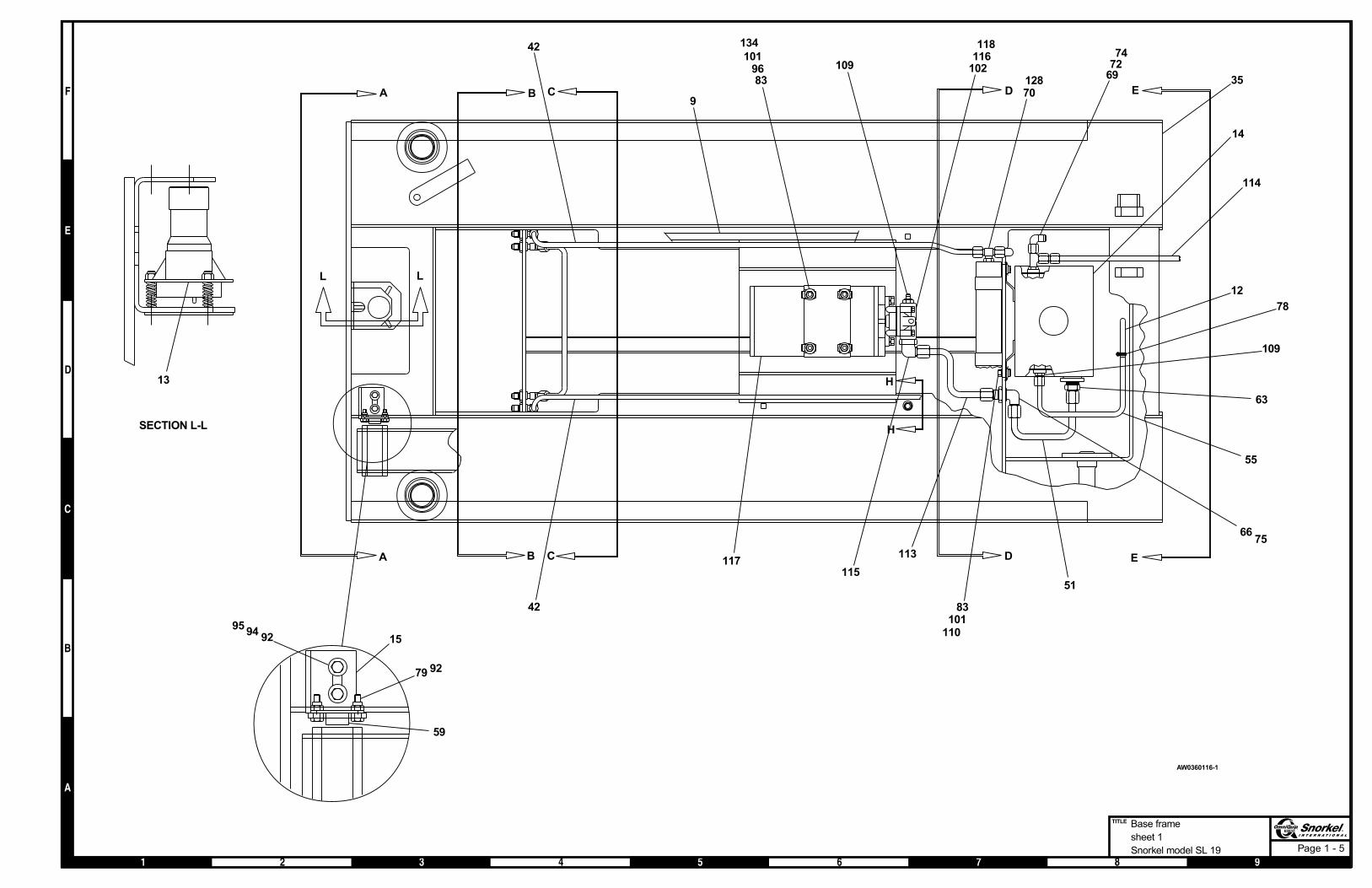
Base frame
sheet 1
Snorkel model SL 19
A B C D E
EDCBA
83
134
96
117
118
109116
102
115
113
55
12
63
697274
14
83
110101
6675
70128
78
109
51
42
35
H
H
101
42
9
LL
114
15
59
9279
9295
94
SECTION L-L
13
AW0360116-1

Page 1 - 6
Base frame
sheet 2
Snorkel model SL 19
677
616
104
61104
88101
3
4
33
F
F
10932
68
125
71
6482
103
31
VIEW A-A
127
11
12280
126
121
DETAIL 1
96
30
30
36
132
45
56
34
39
28
29
256482
1180
SECTION B-B
97
140
141
40
1918
26
60
26
48
16
1780
96
27104
23
8096
16
43
524
99
54
53
9181
65108
107108
29
846
99
22
4525
21
41 20
268096
48
27
1819
104
23
26 8017
96
16
6097
SECTION C-C
8
104
97104
8
44135136
100140
1918
27 10423
261780
9649
49
6050
97104
8
2680
9648
8527
104
23
1819
17
8096
97
104
88096
48
2499
29
846
99
20
2545
44
SECTION D-D
43124
125
123
70
I
I J
J
100
135136
140
5 26
60
26
50
VIEW F-F
73
6482
68
32
106
AW0360116-2

Page 1 - 7
Base frame
sheet 3
Snorkel model SL 19
62
86
38
76 96
57
47
105
52105
67
60104
2
VIEW E-E
131
118096
84
84
80
132
90
SECTION I-I
77
96133
9680
77
9680
96133
SECTION J-J
131
13096
13096
131
SECTION G-G
119
112
SECTION H-H
76
80
80 GNDLS
GNDBX
GNDDN
GROUND WIRES
FROM MAIN
HARNESS
129
93
DETAIL K
137
139
37
120
98103
138
38
8779
95
9279
20
59
DETAIL M
10
AW0360116-3


Bearing hub
item part no qty description
301480 2 Bearing hub
1 301479 1 Hub
2 2540012 2 Bearing cup
3 034377 2 Bearing cone
4 034387 1 Grease seal
5 301507 1 Dust cap
SL 19 – 01-97 through 01-01 1 - 9
1
23
4
5
AW301480

Hydraulic tray
item part no qty description
1 301698 1 Hydraulic tray
2 301804 1 Lower control box - (see page 3-5 for parts breakdown)
3 301434 1 Control valve, main - (see page 2-2 for parts breakdown)
4 301440 1 Return filter
5080025 1 Replacement filter element
5 301428 1 Oil drain pan
6 300437 2 Bearing flange
7 301743 1 Battery cable, standard
301742 1 Battery cable, quick disconnect
8 300909 1 Battery charger, standard
300755 1 Battery charger, world
9 5093027 1 Clamp
10 5076003 2 Reducer-expander
11 5035320 2 Straight thread 90° elbow
12 5560082 1 Trim lock, 1/4 inch x 10 inches long
13 5569930 3 Capscrew 3/8-16 x 3/4 inch long button head
14 970029 2 Capscrew 1/4-20 x 3/4 inch long hex head grade 5
15 970469 2 Capscrew 3/8-16 x 1 inch long hex head grade 5
16 972589 2 Carriage bolt 1/4-20 x 1 inch long
17 972439 6 Carriage bolt 3/8-16 x 1-1/4 inch long
18 3044836 2 Terminal ring tongue insulated 12/10 wire
19 986269 6 Washer 5/16 medium flat
20 986299 2 Washer 3/8 medium flat
21 987099 2 Washer 1/4 medium lock
22 987119 2 Washer 3/8 medium lock
23 5560004 2 Nut 1/4-20 self locking
24 5560033 6 Nut 3/8-16 self locking
25 5093008 5 Clamp
26 3040269 3 Insulator boot
27 0020271 2 3/8 inch hydraulic hose
28 0020273 1 3/8 inch hydraulic hose
29 0020275 1 3/8 inch hydraulic hose
30 0050137 1 1/4 inch hydraulic hose
31 0070771 2 1/4 inch hydraulic hose
32 0070764 1 3/8 inch hydraulic hose
33 0101896 1 1/4 inch hydraulic hose
34 0070703 1 Battery wire
35 300228 1 Platform control cable - (see page 3-14 for replacement parts)
36 0360098 1 Wire harness, main - (see page 3-16 for replacement parts)
1 - 10 SL 19 – 01-97 through 01-01
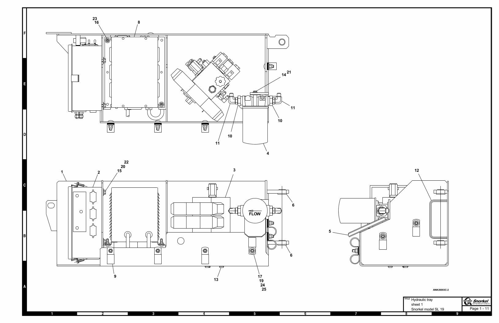
Page 1 - 11
Hydraulic tray
sheet 1
Snorkel model SL 19
1623
8
4
10
11
10
11
1421
6
6
5
12
25
171924
13
321 15
2022
FLOW
9
AWA36003C-2

Page 1 - 12
Hydraulic tray
sheet 2
Snorkel model SL 19
PUMP/MOTOR
HYDRAULIC
RESERVOIR
RETURN FILTER
BRAKE CYLINDERS
CUSHIONCYLINDER
STEER CYLINDER
HYDRAULIC TRAY
TO LIFTCYLINDER
29
30
32
27
31
31
28
TO LEFT DRIVEMOTOR PORT "A"
TO RIGHT DRIVEMOTOR PORT "A"
MANIFOLD VALVE
(BACK)(RH SIDE)(LH SIDE)
FWD
DRIVE
REV
DRIVE
BRAKE
LIFT
T
P
LEFT
STR.
RT.
STR.
33
4
333
27
AWA36003C-3
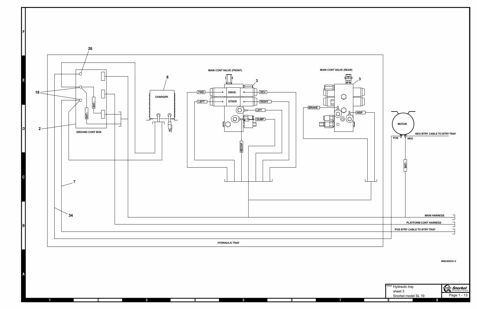
Page 1 - 13
HISP
BA
T--
MAIN CONT VALVE (REAR)
BRAKE
GROUND CONT BOX
MOTOR
NEGPOS
DRIVE
STEER
MAIN CONT VALVE (FRONT)
HYDRAULICTRAY
MAIN HARNESS
PLATFORM CONT HARNESS
POS BTRY CABLE TO BTRY TRAY
RIGHTLEFT
REVFWD
LIFT
DUMP
ME
DS
P
NEG BTRY CABLE TO BTRY TRAY
CHARGER
BA
T--
BA
T--
338
2
7
18
26
34
AWA36003C-4
Hydraulic tray
sheet 3
Snorkel model SL 19

Battery tray
item part no qty description
1 0090318 3 Battery wire
2 300437 2 Bearing flange
3 5560350 6 Carriage bolt 3/8-16 x 1 inch long
4 301215 1 Battery tray
5 301687 1 Plate, battery hold down
6 301411 1 Bracket, battery tray
7 986269 6 Washer 5/16 medium flat
8 3040269 8 Insulator boot
9 5093004 4 Clamp
10 5560033 6 Nut 3/8-16 self locking
11 301686 1 Angle, plastic battery insulator
12 3050009 4 Battery, 6 volt DC - 220 amp hour
3050023 4 Battery, 6 volt DC - 220 amp hour - (Exide)
13 301412 1 Battery cable, standard
14 969999 2 Capscrew 1/4-20 x 2-1/4 inch long hex head grade 5
15 986019 6 Washer 1/4 medium flat
16 5560004 2 Nut 1/4-20 self locking
17 301504 1 Battery cable, quick disconnect
1 - 14 SL 19 – 01-97 through 01-01

Battery tray
SL 19 – 01-97 through 01-01 1 - 15
+ (POS) BATTERY CABLE
- (NEG) BATTERY CABLE
+
-
+
-
+
-
+
-
12
3
63
710
7
10
2
2
13
8
9
37
10
1
14
18
1516QUICK DISCONNECT
ELECTRICAL SYSTEM
37910
4
11
5
AW301414

Scissor arm mounting
item part no qty description
1 986359 2 Washer 1/2 medium flat
2 986039 8 Washer 3/8 wide flat
3 986029 2 Washer 5/16 wide flat
4 5569927 1 Washer 1/4 wide flat
5 5560031 6 Nut 5/16-18 self locking
6 302802 1 Proximity switch
7 971069 1 Capscrew 1/2-13 x 2-3/4 inch long hex head grade 5
8 972479 4 Capscrew 3/8-16 x 1-1/4 inch long hex head grade 5
9 5569897 6 Capscrew 5/16-18 x 2-1/4 inch long hex head grade 5
10 970239 1 Capscrew 5/16-18 x 3/4 inch long hex head grade 5
11 5560033 4 Nut 3/8-16 self locking
12 5560004 5 Nut 1/4-20 self locking
13 5065705 2 Straight thread adapter
14 989579 2 Roll pin 3/8 inch diameter x 2 inch long
15 0360083 2 Split collar
16 0360034 2 Slider block, platform
17 0360039 2 Slider block, base frame
18 0360001 1 Scissor arm stack - (see page 1-19 for parts breakdown)
19 0360023 2 Pin, slider base
20 0360025 4 Pin, platform pivot
21 301366 1 Bracket, bleed down
22 301365 1 Bracket, bleed down
23 0360032 1 Slider shaft
24 0360074 2 Tube
25 0360041 1 Safety prop
26 0360044 1 Bracket
27 300719 1 Lift cylinder cartridge valve - (see page 2-13 for parts breakdown)
28 986129 1 Washer 1-1/4 wide flat
29 300720 1 Check valve, orificed
30 5550060 2 Clamp
31 9980005 1 Cable tie
32 301726 1 Level sensor, 2° non-adjustable
33 5025003 1 Swivel adapter
34 5063905 1 Fitting nut
35 5064001 1 Tube end reducer
36 5065707 1 Straight thread adapter
37 5093004 7 Clamp
38 970009 4 Capscrew 1/4-20 x 1/2 inch long hex head grade 5
39 5560712 1 Machine bushing 1-7/8 inch OD x 1-1/4 inch ID x 14 gauge thick
40 970009 3 Capscrew 1/4-20 x 1/2 inch long hex head grade 5
41 986019 7 Washer 1/4 medium flat
42 987099 2 Washer 1/4 medium lock
43 0100271 1 1/4 inch hydraulic hose
1 - 16 SL 19 – 01-97 through 01-01

Page 1 - 17
Scissor arm mounting
Snorkel model SL 19
209
5
2095
1ST INNER ARM
2ND INNER ARM
3RD INNER ARM
4TH INNER ARM
16
17
24 9 5
19
25
A
30
18
26
39
HOSE ASSY-LIFT CYL
MAIN ELECT HARNESS
HOSE ASSY-LIFT CYL. (PRESSURE)
PLATFORM CONTROL WIRE
1ST INNER ARM (TOP VIEW)
2ND INNER ARM (TOP VIEW)
3RD INNER ARM (TOP VIEW)
4TH INNER ARM (TOP VIEW)
43
16
1523
17
31
31
14
6
32
25
37
3738
1240
41
41
42
28
118
DETAIL B
TO HYDTRAY (PRESSURE)
TO HYDTRAY (RESERVOIR)
LIFT CYLINDER
13
3629
21
310
1227
22 4
MAIN ELECT
HARNESS
DETAIL A
36
33
29
34
35
2
SPRING
RETURN ROLLER
SEE DETAIL B
CIRCUIT DOWN
CIRCUIT GNDDN
AW0360117

Page 1 - 18
Scissor arm stack
Snorkel model SL 19
101112
10
7
55
55
12
3
4
1112
A
6
21
162015
17
DETAIL A
18
19
2223
98
1314
AW0360001
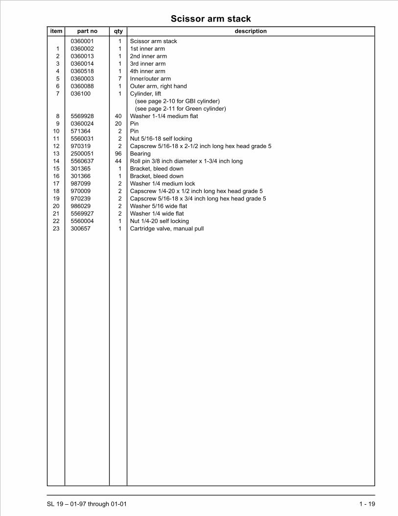
Scissor arm stack
item part no qty description
0360001 1 Scissor arm stack
1 0360002 1 1st inner arm
2 0360013 1 2nd inner arm
3 0360014 1 3rd inner arm
4 0360518 1 4th inner arm
5 0360003 7 Inner/outer arm
6 0360088 1 Outer arm, right hand
7 036100 1 Cylinder, lift
(see page 2-10 for GBI cylinder)
(see page 2-11 for Green cylinder)
8 5569928 40 Washer 1-1/4 medium flat
9 0360024 20 Pin
10 571364 2 Pin
11 5560031 2 Nut 5/16-18 self locking
12 970319 2 Capscrew 5/16-18 x 2-1/2 inch long hex head grade 5
13 2500051 96 Bearing
14 5560637 44 Roll pin 3/8 inch diameter x 1-3/4 inch long
15 301365 1 Bracket, bleed down
16 301366 1 Bracket, bleed down
17 987099 2 Washer 1/4 medium lock
18 970009 2 Capscrew 1/4-20 x 1/2 inch long hex head grade 5
19 970239 2 Capscrew 5/16-18 x 3/4 inch long hex head grade 5
20 986029 2 Washer 5/16 wide flat
21 5569927 2 Washer 1/4 wide flat
22 5560004 1 Nut 1/4-20 self locking
23 300657 1 Cartridge valve, manual pull
SL 19 – 01-97 through 01-01 1 - 19

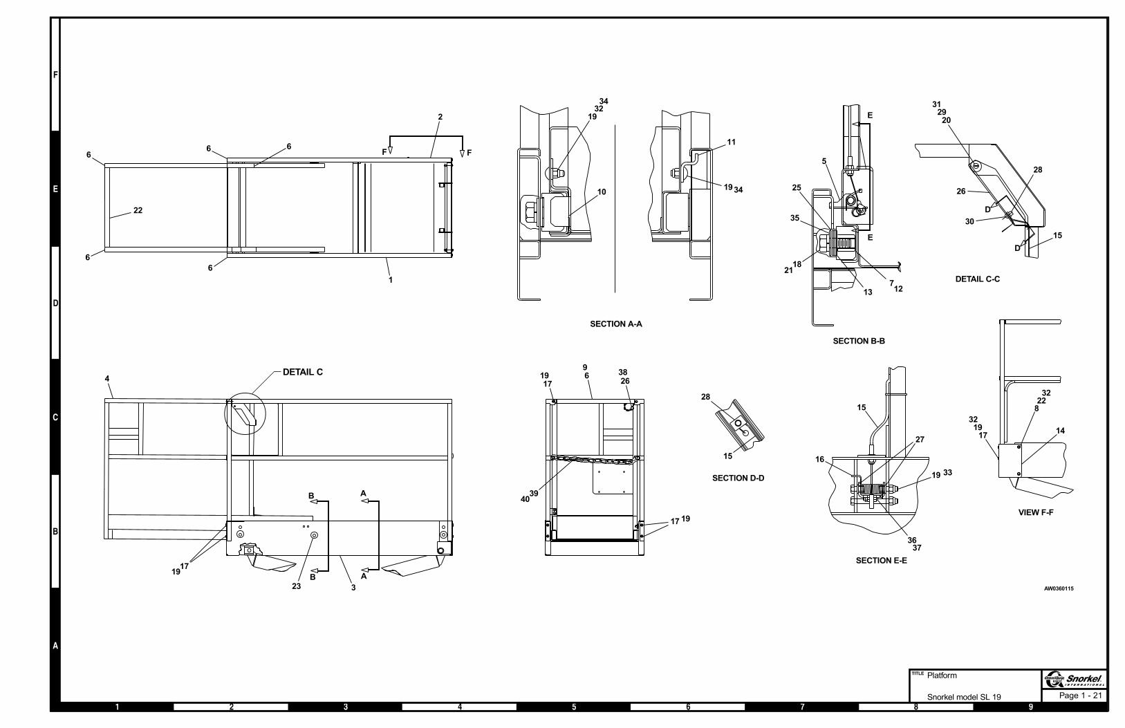
Platform
item part no qty description
1 0360021 1 Side guard rail, left hand
2 0360019 1 Side guard rail, right hand
3 0360103 1 Platform
4 0360005 1 Extension deck
5 302920 1 Detent paddle
6 468886 7 End cap, 1-1/2 inch square plastic
7 583326 4 Roller, extension deck
8 5560031 2 Nut 5/16-18 self locking
9 301260 1 Cross rail
10 301677 1 Bracket, detent stop
11 301387 1 Guide
12 592114 4 Slider mount
13 5569852 2 Machine bushing 2 inch OD x 1-1/4 inch ID x 14 gauge thick
14 0360082 1 Cover, platform cable
15 302722 1 Cable
16 302723 1 Torsion spring
17 970519 9 Capscrew 3/8-16 x 2-1/4 inch long hex head grade 5
18 970499 4 Capscrew 3/8-16 x 1-3/4 inch long hex head grade 5
19 5560033 15 Nut 3/8-16 self locking
20 5560004 1 Nut 1/4-20 self locking
21 987179 4 Washer 3/4 medium lock
22 970249 2 Capscrew 5/16-18 x 7/8 inch long hex head grade 5
23 583406 5 Plug, plastic 2 inch diameter
24 455006 1 Pin, spiral 1-1/8 inch diameter
25 986309 8 Washer hard flat 1-7/8 inch OD x 3/4 inch ID
26 302717 1 Detent trigger
27 2572009 2 Bushing
28 5560278 1 Propeller nut
29 5569929 1 Carriage bolt 1/4-20 x 2 inch long
30 5560677 1 Capscrew 5/16-18 x 1/2 inch long socket button head
31 986019 2 Washer 1/4 medium flat
32 986269 6 Washer 5/16 medium flat
33 970569 2 Capscrew 3/8-16 x 3-1/2 inch long hex head grade 5
34 970469 4 Capscrew 3/8-16 x 1 inch long hex head grade 5
35 592144 4 Washer special 3/4 flat zinc plated
36 5569845 1 Machine screw #10-24 x 1 inch long hex head grade 5
37 5560034 1 Nut #10-24 self locking
38 5580002 1 Snapper pin
39 301682 1 Entry chain gate
40 301497 1 Threaded connector link
1 - 20 SL 19 – 01-97 through 01-01
Page 1 - 21
Platform
Snorkel model SL 19
B
B
A
A
323
1917
4
VIEW F-F
F F
2
6
66
6
22
6
1
14
228
32
1719
32
9619
17
17 19
3940
3826
SECTION A-A
11
193410
1932
34
15
16
27
19
3637
33
SECTION E-E
SECTION B-B
E
E
5
2118
13712
25
35
DETAIL C-C
D
D
30
26
2920
31
15
28
SECTION D-D
28
15
DETAIL C
AW0360115

Page 1 - 22
Placards and decals
Snorkel model SL 19
9307000001
5
2
2
1036
9 37
21
28 2811
3329
29
29
2828
11
17
LEFT SIDE VIEW
REAR VIEW
FRONT VIEW
RIGHT SIDE VIEW
3031
41 12
5
16
10
1 4
15
39
18
14
15
14
3
7
29
26
26
25
24
6
3123
24
REAR VIEW
BRAKE COVER REMOVED
34
22
34
TOP VIEW
BASE FRAME
38 27
28
28
20
19
13
29
SAFETY PROP
UPPERCONTROL BOX
8
35
AW0360118

Placards and decals
item part no qty description
1 0073585 2 Decal, made in USA
2 480658 2 Decal, danger tipover/electrical hazard
3 0181562 1 Placard, ANSI standard
4 560239 2 Decal, Snorkel brand logo
5 300698 2 Decal, Snorkel logo
6 300699 1 Decal, Snorkel logo
7 300700 1 Decal, danger shearing/crushing
8 302781 1 Placard, upper control box
9 301741 1 Placard, lower control box
10 300740 2 Decal, danger towing instructions
11 300760 2 Decal, danger tipover hazard
12 0360076 2 Decal, SL 19 logo
13 569255 1 Safety tread 3 inch x 6 inch
14 301476 2 Decal, danger safety prop
15 2 Decal, platform capacity - (consult factory)
16 0070420 1 Placard, emergency bleed down valve
17 416836 1 Decal, battery charge
18 451726 1 Decal, check battery before charging
19 451776 1 Decal, hydraulic fluid level
20 451986 2 Placard, danger do not alter switch
21 302950 1 Decal, hydraulic oil level
22 475596 2 Decal, caution cylinder disassembly
23 5560004 2 Nut 1/4-20 self locking
24 562386 1 Literature compartment
25 562426 1 Decal, operating manual enclosed
26 7030004 2 Decal, OmniQuip logo
27 301667 1 Ground strap
28 621486 6 Decal, fork lift here
29 969249 1 Decal, warning stripes x 134 inches long
30 0070901 1 Placard, caution serial number
31 970009 2 Capscrew 1/4-20 x 1/2 inch long hex head grade 5
32 978109 4 Drive screw #4 x 5/16 inch long PK type U
33 9980003 1 Foam pipe wrap x 19 inches long
34 0074311 3 Decal, danger cylinder failure - (1 per cylinder)
35 0072545 1 Decal, emergency stop
36 301695 1 Decal, hydraulic schematic
37 301803 1 Decal, lower control schematic
38 7030002 1 Decal, lube recommendations
SL 19 – 01-97 through 01-01 1 - 23

Covers
item part no qty description
1 0360777 1 Cover plate
2 0360067 1 Base frame cover, front
3 0360056 1 Brake cylinder cover
4 25560083 1 Trim lock x 96 inches long
5 5560031 4 Nut 5/16-18 self locking
6 5560033 4 Nut 3/8-16 self locking
7 986269 4 Washer 5/16 medium flat
8 970269 4 Capscrew 5/16-18 x 1-1/4 inch long hex head grade 5
9 978629 4 Capscrew 1/4-20 x 1/2 inch long self tapping type B
10 5560350 4 Carriage bolt 3/8-16 x 1 inch long
1 - 24 SL 19 – 01-97 through 01-01
3
6 10
1 4
578
9
9 9
2 4
AWM00314

Section 2. - Hydraulics
SL 19 – 01-97 through 01-01 2 - 1

Control valve, main
item part no qty description
301434 1 Control valve, main
1 301691 1 Manifold valve - (see page 2-4 for parts breakdown)
2 5065803 1 Long straight thread adapter
3 5037003 2 Swivel nut 90° elbow
4 5065703 2 Straight thread adapter
5 5035305 2 Straight thread 90° elbow
6 5035303 1 Straight thread 90° elbow
7 5070005 1 Diagnostic nipple
8 5035318 1 Straight thread 90° elbow
9 5065806 1 Long straight thread adapter
10 0070908 1 1/4 inch hydraulic hose
11 5065707 1 Straight thread adapter
12 302818 1 Decal set, valve
13 5075203 2 Hex head plug
14 5064003 1 Tube end reducer
15 5034802 1 Connector
16 5063906 1 Fitting nut
2 - 2 SL 19 – 01-97 through 01-01

Control valve, main
SL 19 – 01-97 through 01-01 2 - 3
STEER
DRIVE
P
T
LIF
T
RS
TE
ER
LS
TE
ER
CU
SH
ION
CU
SH
ION
RIG
HT
RE
V
LE
FT
FW
D
BRAKE
REV DRIVE
F DRIVE
13
13
23
43
128
12
12
12
11
9
1614
5
5
6
12
7
15
10
4
12
AW301434

Manifold valve
item part no qty description
301691 1 Manifold valve
1 6010719 1 Check valve cartridge
565666 1 Seal repair kit
2 6010779 1 Relief valve cartridge
6018018 1 Seal repair kit
3 6010780 1 Relief valve cartridge
6018018 1 Seal repair kit
4 6010781 2 Relief valve cartridge
6018018 1 Seal repair kit
5 6010782 1 Relief valve cartridge
6018018 1 Seal repair kit
6 6010816 1 Flow control cartridge valve
6018018 1 Seal repair kit
7 6010815 1 Flow control cartridge valve
6018019 1 Seal repair kit
8 301501 1 Flow control cartridge valve
6018018 1 Seal repair kit
9 6010787 2 Solenoid valve
3049853 1 Seal repair kit
8220193 1 Replacement cartridge
8220194 1 Replacement solenoid, 24 volt DC
10 6010789 1 Solenoid valve
3040853 1 Seal repair kit
8220195 1 Replacement cartridge
8220194 1 Replacement solenoid, 24 volt DC
11 6010717 2 Solenoid valve
6010537 1 Seal repair kit
6010707 1 Replacement cartridge
3040554 1 Replacement solenoid, 24 volt DC
12 6010886 2 Directional control valve section
3040680 2 Replacement solenoid, 24 volt DC
13 6010292 1 Manual bleed down cartridge valve
0150567 1 Seal repair kit
8060188 1 Replacement knob
14 6010782 1 Relief valve cartridge
6018018 1 Seal repair kit
15 6010813 1 Orifice disc, .030 inch diameter
16 6010792 1 Counterbalance pilot piston
2 - 4 SL 19 – 01-97 through 01-01

Manifold valve
SL 19 – 01-97 through 01-01 2 - 5
79 11
12 12
1
10
113
516
4
2
14 - installed in port
9
815
6
4
13
AW301691

Cylinder, brake - Green
item part no qty description
590984 1 Cylinder, brake - Green
8070203 1 Seal repair kit - (kit includes items 13 through 20)
1 1 Cylinder barrel - (not sold separately)
2 8070990 1 Rod
3 8070976 1 Spring retainer
4 8070977 1 Spring
5 8070979 1 Spring cap
6 8070939 1 Full lock nut
7 8070940 1 Piston
8 8070944 1 Washer
9 8070237 1 Lockwire
10 8070878 1 Head
11 8070871 1 O-ring
12 8070872 1 Back-up
13 Kit item 1 O-ring - (not sold separately)
14 Kit item 2 Back-up - (not sold separately)
15 Kit item 1 O-ring - (not sold separately)
16 Kit item 1 O-ring - (not sold separately)
17 Kit item 1 Back-up - (not sold separately)
18 Kit item 1 O-ring - (not sold separately)
19 Kit item 1 Back-up - (not sold separately)
20 Kit item 1 Rod wiper - (not sold separately)
2 - 6 SL 19 – 01-97 through 01-01
43 1
5
6 87
1314
18
20
2
19
1112
109
1617
15
AWV00355

Cylinder, brake - Prince
item part no qty description
590984 1 Cylinder, brake - Prince
8160431 1 Seal repair kit - (kit includes items 11 through 16)
1 1 Butt and tube - (not sold separately)
2 8160432 1 Piston rod
3 8160434 1 Piston
4 8160368 1 Gland
5 8160423 1 Locknut
6 8160424 1 Spring
7 8160425 1 Washer
8 8160426 1 Washer
9 8160394 1 Snap ring
10 8160427 1 Rod and wiper cover
11 Kit item 1 O-ring - (not sold separately)
12 Kit item 1 O-ring - (not sold separately)
13 Kit item 1 Back-up - (not sold separately)
14 Kit item 2 O-ring - (not sold separately)
15 Kit item 3 Back-up - (not sold separately)
16 Kit item 1 Wiper - (not sold separately)
SL 19 – 01-97 through 01-01 2 - 7
1
6
7
5
3 1415
1415
11
8 10
2
4
1213
9
16
AWV00348

Cylinder, brake - Rosenboom
item part no qty description
590984 1 Cylinder, brake - Rosenboom
6091417 1 Seal repair kit - (kit includes items 9 through 15)
1 1 Tube - (not sold separately)
2 6091338 1 Support washer
3 6091340 1 Head gland
4 6091342 1 Capscrew 7/16-14 flange bolt grade 8
5 6091414 1 Rod
6 458916 1 Die spring
7 6091415 1 Piston
8 6091416 1 Spring guide
9 Kit item 1 Snap ring - (not sold separately)
10 Kit item 1 O-ring - (not sold separately)
11 Kit item 1 Back-up - (not sold separately)
12 Kit item 1 Crown seal - (not sold separately)
13 Kit item 1 Deep Z-seal - (not sold separately)
14 Kit item 1 Rod wiper - (not sold separately)
15 Kit item 1 Square wrap-in wire - (not sold separately)
2 - 8 SL 19 – 01-97 through 01-01
6 2 3415
7
8 91011
1213
1415
AW590984

Cylinder, cushion - Green
item part no qty description
594184 1 Cylinder, cushion - Green
8070981 1 Seal repair kit before 9-13-99 - (kit includes items 5, 6 and 7)
8070998 1 Seal repair kit after 9-13-99 - (kit includes item 7 and 8)
1 1 Cylinder barrel - (not sold separately)
2 8070983 1 Piston, before 9-13-99
8070999 1 Piston, after 9-13-99
3 8070984 2 Compression spring
4 8070982 2 End cap, before 9-13-99
8070982 1 End cap, after 9-13-99
5 Kit item 1 O-ring - (not sold separately)
6 Kit item 2 Back-up - (not sold separately)
7 Kit item 2 O-ring - (not sold separately)
8 Kit item 1 Piston seal - (not sold separately)
9 Kit item 1 O-ring - (not sold separately)
SL 19 – 01-97 through 01-01 2 - 9
23 3
1
6 5 64 477
After 9-13-99
Before 9-13-99
1AWV00338
849
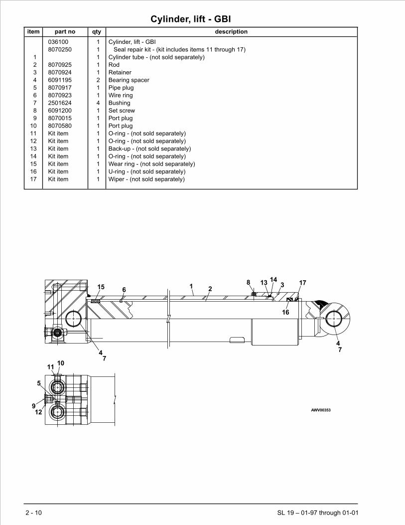
Cylinder, lift - GBI
item part no qty description
036100 1 Cylinder, lift - GBI
8070250 1 Seal repair kit - (kit includes items 11 through 17)
1 1 Cylinder tube - (not sold separately)
2 8070925 1 Rod
3 8070924 1 Retainer
4 6091195 2 Bearing spacer
5 8070917 1 Pipe plug
6 8070923 1 Wire ring
7 2501624 4 Bushing
8 6091200 1 Set screw
9 8070015 1 Port plug
10 8070580 1 Port plug
11 Kit item 1 O-ring - (not sold separately)
12 Kit item 1 O-ring - (not sold separately)
13 Kit item 1 Back-up - (not sold separately)
14 Kit item 1 O-ring - (not sold separately)
15 Kit item 1 Wear ring - (not sold separately)
16 Kit item 1 U-ring - (not sold separately)
17 Kit item 1 Wiper - (not sold separately)
2 - 10 SL 19 – 01-97 through 01-01
1011
5
912
47
615 1 2
16
1714
3138
47
AWV00353
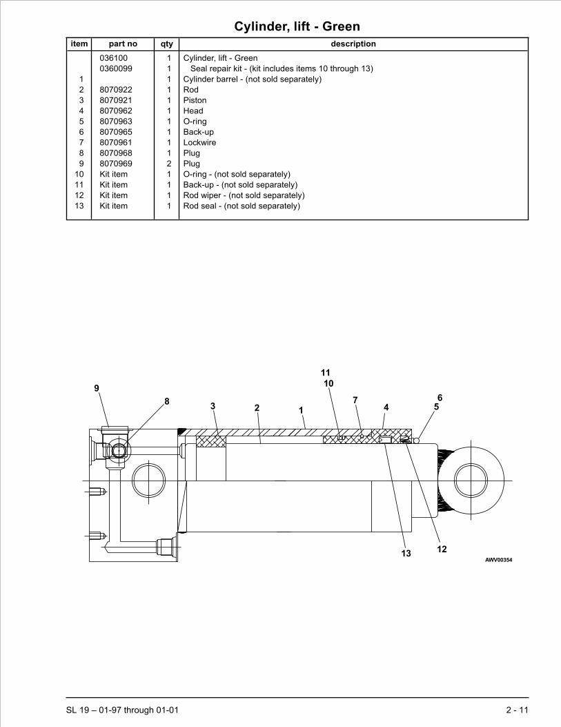
Cylinder, lift - Green
item part no qty description
036100 1 Cylinder, lift - Green
0360099 1 Seal repair kit - (kit includes items 10 through 13)
1 1 Cylinder barrel - (not sold separately)
2 8070922 1 Rod
3 8070921 1 Piston
4 8070962 1 Head
5 8070963 1 O-ring
6 8070965 1 Back-up
7 8070961 1 Lockwire
8 8070968 1 Plug
9 8070969 2 Plug
10 Kit item 1 O-ring - (not sold separately)
11 Kit item 1 Back-up - (not sold separately)
12 Kit item 1 Rod wiper - (not sold separately)
13 Kit item 1 Rod seal - (not sold separately)
SL 19 – 01-97 through 01-01 2 - 11
56
12
4
13
7
1011
1238
9
AWV00354

Cylinder, steering - Green
item part no qty description
301473 1 Cylinder, steering - Green
8070203 1 Seal repair kit - (kit includes items 11 through 18)
1 1 Cylinder barrel - (not sold separately)
2 8070258 1 Rod
3 8070878 1 Head
4 8070940 1 Piston
5 8070944 1 Washer
6 28070241 1 Clevis
7 8070237 1 Lockwire
8 8070939 1 Full lock nut
9 8070871 1 O-ring
10 8070872 1 Back-up
11 Kit item 1 O-ring - (not sold separately)
12 Kit item 2 Back-up - (not sold separately)
13 Kit item 1 O-ring - (not sold separately)
14 Kit item 1 O-ring - (not sold separately)
15 Kit item 1 Back-up - (not sold separately)
16 Kit item 1 O-ring - (not sold separately)
17 Kit item 1 Back-up - (not sold separately)
18 Kit item 1 Rod wiper - (not sold separately)
2 - 12 SL 19 – 01-97 through 01-01
6
910
18
1617
8
1415
3
1
2
45
11
12
138
AWV00337

Lift cylinder cartridge valve
item part no qty description
300719 1 Lift cylinder cartridge valve
565666 1 Seal repair kit
1 6010509 1 Replacement cartridge valve
2 3040458 1 Replacement solenoid, 24 volt DC
SL 19 – 01-97 through 01-01 2 - 13
2
1
AW300719

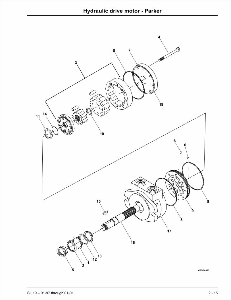
Hydraulic drive motor - Parker
item part no qty description
301433 1 Hydraulic drive motor
8160481 1 Seal repair kit - (kit includes items 2, 8 and 14)
1 8160469 1 Snap ring
2 Kit item 1 Seal/retainer assembly
3 8160478 1 IGR assembly
4 8160472 8 Capscrew 5/16-24
5 8160480 1 Nut 1-20 slotted hex
6 8160470 2 Check valve ball
7 8160484 1 Vent plug 7/16-20 with o-ring
8 Kit item 3 Square ring
9 8160485 1 Commuter plate
10 8160477 1 Snap ring
11 8160473 1 Thrust washer
12 8160474 1 Thrust washer
13 8160475 1 Thrust washer
14 Kit item 1 O-ring
15 8160479 1 Woodruff key
16 8160482 1 Shaft 1-1/4 inch taper
17 1 Body - (not sold separately)
18 8160483 1 Cover/bearing assembly
2 - 14 SL 19 – 01-97 through 01-01
Hydraulic drive motor - Parker
SL 19 – 01-97 through 01-01 2 - 15
5
12
1213
16
15
17
8
9
8
66
4
8
3
1114
10
18
7
AWV00365

Hydraulic drive motor - White
item part no qty description
301433 1 Hydraulic drive motor
8230130 1 Seal repair kit - (kit includes items 1 through 12)
1 Kit item 1 Dust seal - (not sold separately)
2 Kit item 1 Split wire ring - (not sold separately)
3 Kit item 1 Metal backup shim - (not sold separately)
4 Kit item 1 High pressure seal - (not sold separately)
5 Kit item 1 Metal backup shim - (not sold separately)
6 Kit item 1 Polyamide seal - (not sold separately)
7 Kit item 1 Shaft seal - (not sold separately)
8 Kit item 1 Rear housing seal - (not sold separately)
9 Kit item 2 Body seal - (not sold separately)
10 Kit item 1 End cover seal - (not sold separately)
11 Kit item 1 Seal carrier - (not sold separately)
12 Kit item 1 Thrust washer - (not sold separately)
13 8230131 1 Rear thrust bearing
14 8230132 1 Front housing bearing
15 1 Housing - (not sold separately)
16 8230134 1 Rear housing bearing
17 8230135 1 Drive link
18 8230136 1 Forward manifold
19 8230137 1 Manifold boot
20 8230138 1 Drive link spacer
21 8230139 1 Rotor
22 8230140 1 Balance plate - (includes item 23)
23 8230141 4 Steel balls
24 8230142 1 End cover
25 8230143 1 Bolt set
26 8230144 1 Shaft, tapered 1-1/4 inch with nut
27 8230145 1 Key
28 8230133 1 Front thrust bearing
2 - 16 SL 19 – 01-97 through 01-01

Hydraulic drive motor - White
SL 19 – 01-97 through 01-01 2 - 17
12
3
411
56
712
28
27
2614
15
16
13
17
9
18
19
920
21 9
22
23
10
24
25
AWV00364


Section 3. - Electrical
SL 19 – 01-97 through 01-01 3 - 1

Lower control box before 3-1-99
item part no qty description
301797 1 Lower control box
1 301714 1 Control
2 301715 1 Gasket kit
3 301716 1 Cover
4 302837 2 Catch
5 302883 1 Drain plug
6 302834 1 Power plate
7 302882 1 Bracket, power plate
8 0070967 1 Corrosion inhibitor
9 300192 1 Fuse block
10 446076 1 Fuse, 250 amp capacity
11 302832 1 Speaker
12 0360759 1 Printed circuit board, lower control box
13 465026 1 Contactor 24 volt DC
14 302824 2 Bus bar
15 455186 1 Hour meter
16 582206 1 Circuit breaker, 5 amp thermal
17 302829 1 Light, red 24 volt DC bezel mount
18 3020016 1 Switch, toggle
19 3020047 2 Switch, toggle
20 562236 1 Guard, emergency stop switch
21 302853 1 Switch, battery disconnect
22 301717 1 Wire harness, lower control box internal
23 584926 2 Battery wire
24 302858 1 Jumper wire
25 302859 1 Jumper wire
26 302860 1 Jumper wire
27 302861 1 Jumper wire
28 302862 1 Jumper wire
29 301741 1 Placard, lower control box
30 302854 1 Poly switch - (service part)
3 - 2 SL 19 – 01-97 through 01-01

Page 3 - 3
Lower control box
before 3-1-99
Snorkel model SL 19
AW301797
1222
23
15
10
14
13
14
24
19
21
19
1825
11
16
28
26
17
27
1314910
67
1230
11
23
291
8
15
16
17
18
19
54
21
1920

Page 3 - 4
18
14 23
20
21
23
24
54
26
24 25
2211
6 7
910
19
19 18 13
12
B
28
GNDSTUD
29
19
19
10
18
122720
22 21
23
24
26
24
11
31
1615
30
-+
+
-
J1-12
J1-9
J1-8
J1-11
J1-10
J1-7
J1-6
J1-5
J1-4
J1-3
J1-2
J1-1
-+
AW301804
Lower control box
after 3-1-99
Snorkel model SL 19

Lower control box after 3-1-99
item part no qty description
301804 1 Lower control box
1 301714 1 Control box
2 301715 1 Gasket kit
3 301716 1 Cover
4 302837 2 Catch
5 302883 1 Drain plug
6 302834 1 Power plate
7 302882 1 Bracket, power plate
8 0070967 1 Corrosion inhibitor
9 300192 1 Fuse block
10 446076 1 Fuse, 250 amp capacity
11 302832 1 Speaker
12 0360759 1 Printed circuit board, lower control box
13 0360818 1 Bracket, contactor
14 301741 1 Placard, lower control box
15 302862 1 Jumper wire
16 302861 1 Jumper wire
17 302860 1 Jumper wire
18 0360814 1 Contactor, 24 volt DC
19 302824 2 Bus bar
20 455186 1 Hour meter
21 582206 1 Circuit breaker, 5 amp thermal
22 302829 1 Light, red 24 volt DC bezel mount
23 3020016 1 Switch, toggle
24 3020047 2 Switch, toggle
25 562236 1 Guard, emergency stop switch
26 302853 1 Switch, battery disconnect
27 301717 1 Wire harness, lower control box internal
28 584926 2 Jumper wire
29 302858 1 Jumper wire
30 302859 1 Jumper wire
SL 19 – 01-97 through 01-01 3 - 5

Upper control box before 12-6-99
item part no qty description
302935 1 Upper control box, before 12-6-99
1 302949 1 Control box housing
2 446826 1 Contact block, emergency stop switch
3 302840 1 Joystick controller
3020033 2 Replacement microswitch
8150099 1 Replacement handle
3020124 1 Replacement handle grip kit
3020125 1 Replacement rocker switch
3020126 1 Replacement rocker switch boot
3020127 1 Replacement enable trigger
3020128 1 Replacement enable switch
8150086 1 Replacement controller boot
4 302841 1 Wire harness, upper control box internal
5 446836 1 Emergency power switch
6 0070967 1 Corrosion inhibitor
7 3020097 1 Switch, toggle
8 302829 1 Light, red 24 volt DC bezel mount
9 302822 1 Gasket kit
10 3049862 1 Connector, 14 pin
3040095 1 Replacement pin
11 302865 1 Jumper wire
12 302866 1 Jumper wire
13 302867 1 Jumper wire
14 302781 1 Placard, upper control box
15 3040342 1 Socket contact
16 3040208 12 Panel nut
17 302863 1 Jumper wire
18 302864 1 Jumper wire
19 446826 1 Contact block, emergency stop switch
20 3040209 1 Panel nut lock washer
3 - 6 SL 19 – 01-97 through 01-01

Page 3 - 7
78
14
6 - inside box
519
3
1
29
1015
1620
5
3
12
811
18
17
7
13
4
10
AW302935
Upper control box
before 12-6-99
Snorkel model SL 19

Page 3 - 8
DRIVE/PLATFORMSELECT SWITCH
123
456
LOW VOLTLIGHTGROUND
HI SPD
JOYSTICK
FWD/UP
REV/DWNMID SPD
1
2
3
4
5
EMERGENCYSTOP SWITCH
A
B
C
D
E
F
G
HJ
K
L
M
NP
8
7
3
9
5
1
6
52
3
12
10
13
8
14 PIN PLATFORM CONTROL CABLE CONN
A
B
C
D
E
F
G
H
J
K
L
M
N
P
MEDIUM SPEED SIGNAL FROM PLATFORM
OPERATOR HORN
GROUND TO PLATFORM (-)
POWER TO PLATFORM (+)
LIFT UP SIGNAL FROM PLATFORM
DRIVE FORWARD SIGNAL FROM PLATFORM
DRIVE REVERSE SIGNAL FROM PLATFORM
STEER LEFT SIGNAL FROM PLATFORM
HIGH SPEED SIGNAL FROM PLATFORM
LOW VOLT LIGHT (+) (PLATF CONT)
LIFT DOWN SIGNAL FROM PLATFORM
STEER RIGHT SIGNAL FROM PLATFORM
AW0360826
Upper control box
after 12-6-99
Snorkel model SL 19
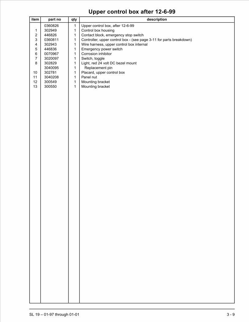
Upper control box after 12-6-99
item part no qty description
0360826 1 Upper control box, after 12-6-99
1 302949 1 Control box housing
2 446826 1 Contact block, emergency stop switch
3 0360811 1 Controller, upper control box - (see page 3-11 for parts breakdown)
4 302943 1 Wire harness, upper control box internal
5 446836 1 Emergency power switch
6 0070967 1 Corrosion inhibitor
7 3020097 1 Switch, toggle
8 302829 1 Light, red 24 volt DC bezel mount
3040095 1 Replacement pin
10 302781 1 Placard, upper control box
11 3040208 1 Panel nut
12 300549 1 Mounting bracket
13 300550 1 Mounting bracket
SL 19 – 01-97 through 01-01 3 - 9

Battery charger
item part no qty description
Battery charger, 115 volt standard
300909 1 Battery charger, standard - Lester
1 8120046 1 Case
2 8120015 1 Transformer
3 8120031 1 Heatsink
4 8120023 1 Capacitor
5 8120013 1 Ammeter
6 8120030 1 Electronic timer
7 3040384 1 Fuse assembly
8 8120035 1 Strain relief bushing, AC cord
9 8120047 1 Cordset, DC
10 8120038 1 Motor base receptacle
Battery charger, 115/230 volt world charger
300755 1 Battery charger, world - Lester
11 8120032 1 Case
12 8120025 1 Transformer
13 8120013 1 Ammeter
14 300938 1 Electronic timer
15 8120033 1 Shunt
16 8120022 2 Heatsink
17 8120034 1 Control cable
18 8120035 1 Strain relief bushing, DC cord
19 8120036 1 Strain relief bushing, AC cord
20 8120026 1 Cordset, AC
21 8120027 1 Cordset, DC
22 8120028 2 Fuse holder
23 8120018 2 Fuse, 6 amp capacity
24 8120007 1 Switch, slide
25 8120029 1 Switch, with wires
26 8120014 1 Circuit breaker, 40 amp
3 - 10 SL 19 – 01-97 through 01-01
AC VOLTS HERTZ MODEL DC VOLTS TYPE
AC AMPS PHASE DC AMPS
120 60
8.5 1
15660 24 24LC25-8ET
25
SERIAL NO.
BATTERY CAPACITY12 CELL SERIES CONNECTED
LEAD-ACID SYSTEMS,180 TO 305AMPERE-HOURS(20 HR. RATE)
U.S. PAT. NO.3,794,905.GR. BR. PAT. NO.1,414,359FR. PATENT NO.2,203,199.W.GR. PAT.NO.2,351,559JAPAN PAT. NO.39133/1978
Lester Electrical OF NEB. INC.
625 West "A" St.,Lincoln,Nebr. 68522
DC
AMPERES
O10 20
30
16369
REPLACE FUSEFROM INSIDE CASE
OPERATING INSTRUCTIONS
AW300909

Controller, upper control box
item part no qty description
0360811 1 Controller, upper control box
3020176 1 Handle kit - (kit includes items 1, 2, 3 and 4)
5560591 1 Hardware kit - (kit includes items 17 and 18)
1 3020184 1 Handle half, front
2 3020185 1 Handle half, back
3 3020186 1 Gasket
4 5560594 4 Assembly screw
5 3020177 1 Side mount nut
6 3020178 1 Trigger lever
7 3020179 1 Rocker
8 3020180 1 Push button, side mounted
9 3020181 1 Handle coupling
10 3020182 1 Coupling setscrew
11 3020183 2 Microswitch
12 3020187 1 Axle rocker
13 3020188 3 Microswitch
14 3020189 1 Terminal board
15 3020190 1 Detent assembly
16 3020191 3 Insulator
17 5560592 1 Trigger axle screw
18 5560593 1 Trigger axle nut
19 8150119 1 Rocker boot
20 8150129 1 Insulator
21 8150131 1 Replacement boot
22 8150136 1 Adapter plate
SL 19 – 01-97 through 01-01 3 - 11
4
2
3
109
11
12
7
19
617
18
85
21
22
13
16
16
20
15
14
1
AW0360811

DC electric motor, Leeson
item part no qty description
3080046 1 Electric motor - 24 volt DC - Leeson
1 3080064 1 Bearing
2 3080065 1 Brush/plate
3 3080066 1 Bearing
4 3080067 2 Brush
5 3080068 1 Spring
6 3080069 1 Arm/shaft
3 - 12 SL 19 – 01-97 through 01-01
3
6
1
4
5
2 AWV3080046

DC electric motor, Ohio
item part no qty description
3080046 1 Electric motor - 24 volt DC - Ohio
1 3080049 1 Brush/ring, complete
2 3080050 4 Brush
3 3080051 4 Brush spring
4 5560585 2 Machine screw #10-24 x 1/2 inch long pan head
5 5560586 4 Washer 3/8 star tooth lock
6 5560587 4 Nut 3/8-16 heavy hex jam
7 970509 2 Capscrew 3/8-16 x 2 inch long hex head grade 5
8 3080052 4 Insulator washer
9 3080053 2 Insulator
10 3080054 1 Bearing
11 3080055 1 Bearing
12 3080056 1 Bearing spring washer
13 3080057 1 Pulley end cover
14 5560588 2 Thru bolt
15 3080058 1 Retaining ring
16 3080059 1 Brush inspection cover
17 3080060 1 Brush inspection cover
18 5560589 1 Machine screw #10-32 x 3/4 inch long pan head
19 5560590 1 Nut #10-24 square
20 3080061 1 Fan
SL 19 – 01-97 through 01-01 3 - 13
13
11
1520142
34
1
10
12
See detail - A
1918
17
16
6
5
8
8
5 7
9
Detail - A
AWV00328
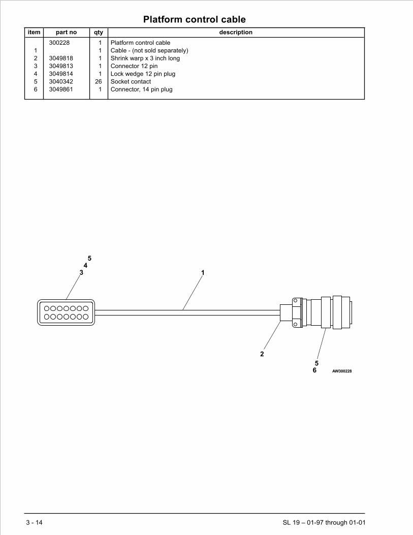
Platform control cable
item part no qty description
300228 1 Platform control cable
1 1 Cable - (not sold separately)
2 3049818 1 Shrink warp x 3 inch long
3 3049813 1 Connector 12 pin
4 3049814 1 Lock wedge 12 pin plug
5 3040342 26 Socket contact
6 3049861 1 Connector, 14 pin plug
3 - 14 SL 19 – 01-97 through 01-01
34
5
2
1
56 AW300228

Proximity switch
item part no qty description
302802 1 Proximity switch
1 3049804 1 Connector 2 pin
2 3049808 1 Lock wedge 2 pin plug
3 3040341 2 Pin, contact
SL 19 – 01-97 through 01-01 3 - 15
12
3 AW302802
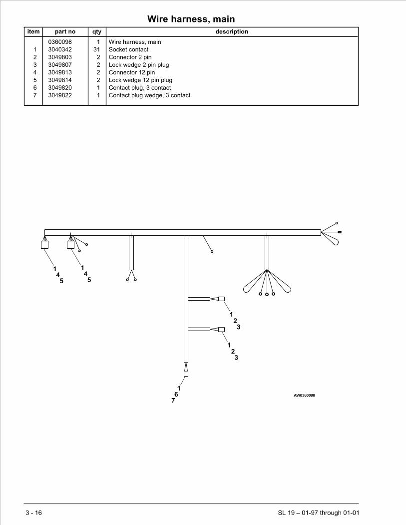
Wire harness, main
item part no qty description
0360098 1 Wire harness, main
1 3040342 31 Socket contact
2 3049803 2 Connector 2 pin
3 3049807 2 Lock wedge 2 pin plug
4 3049813 2 Connector 12 pin
5 3049814 2 Lock wedge 12 pin plug
6 3049820 1 Contact plug, 3 contact
7 3049822 1 Contact plug wedge, 3 contact
3 - 16 SL 19 – 01-97 through 01-01
1 14 45 5
123
123
16
7AW0360098

Section 4. - Factory installed options
SL 19 – 01-97 through 01-01 4 - 1

AC outlet on platform, GFCI
item part no qty description
1 6066149 1 AC outlet mounting strip
2 3040297 1 Electrical outlet box
3 0150606 1 Decal, 125 volt 15 amp power to platform
4 3040397 3 Terminal #8 spade 12/10 wire
5 3040115 1 Connector
6 974679 2 Machine screw #10-24 x 5/8 inch long round head
7 984049 4 Nut #10-24 hex
8 987089 2 Washer #10 medium lock
9 986269 1 Washer 5/16 medium flat
10 5560350 1 Carriage bolt 3/8-16 x 1 inch long
11 5560033 1 Nut 3/8-16 self locking
12 238396 1 Plug male 125 volt AC
13 3040624 1 Electrical outlet, GFCI - 20 amp capacity
14 3040625 1 Cover, GFCI electrical outlet
4 - 2 SL 19 – 01-97 through 01-01

AC outlet on platform, GFCI
SL 19 – 01-97 through 01-01 4 - 3
3
12
910
11
67
8
13
14
14
125
12
4
2
GREEN
GREEN
GREENWHITE
WHITEBLACK
BLACK
AW0360096

Battery condition indicator
item part no qty description
1 487696 1 Gauge, battery condition indicator
2 7110031 1 O-ring
3 300802 1 Jumper wire
4 0181103 1 Jumper wire
4 - 4 SL 19 – 01-97 through 01-01
Upper control box
12
3
4
AW302850-1
5

Dual lanyard attachment
item part no qty description
1 0360892 2 Tie down D ring
2 0360891 2 Bracket, lanyard attachment
3 0360893 2 Plate, lanyard attachment
4 5560704 4 Capscrew 3/8-16 x 1-1/4 inch long hex head grade 8
5 986299 4 Washer 3/8 medium flat
6 5560033 4 Nut 3/8-16 self locking
7 0150448 2 Decal, attach fall restraint
SL 19 – 01-97 through 01-01 4 - 5
A A
B
B
7
SECTION A-A SECTION B-B
12
3
1
2
456
456
3
AWA36030B-3

Flashing light
item part no qty description
1 3014949 1 Angle, light mount
2 302847 1 Wire harness, flashing light
3 3040082 1 Terminal .250 tab male slip-on fully insulated 16/14 wire
4 3040083 1 Terminal .250 tab female slip-on fully insulated 16/14 wire
5 487686 1 Guard, flashing light
6 5093019 2 Clamp
7 564136 1 Flashing light, yellow
300159 1 Flashing light, blue
8 5560004 4 Nut 1/4-20 self locking
9 970049 4 Capscrew 1/4-20 x 1 inch long hex head grade 5
10 986019 8 Washer 1/4 wide flat
11 974689 2 Machine screw #10-24 x 3/4 inch long round head
12 5560034 2 Nut #10-24 self locking
13 986009 4 Washer #10 medium flat
14 3040046 1 Terminal .250 tab male slip-on fully insulated 22/18 wire
15 3040047 1 Terminal .250 tab female slip-on fully insulated 22/18 wire
16 302849 1 Wire harness, motion lights
17 3049809 1 Strain relief
4 - 6 SL 19 – 01-97 through 01-01
WHT
BLK
RED
BLK
BLK WHT
5
14 4
15 3
2
7
17
16
2
1098
7
5
6
89
10
AW302848
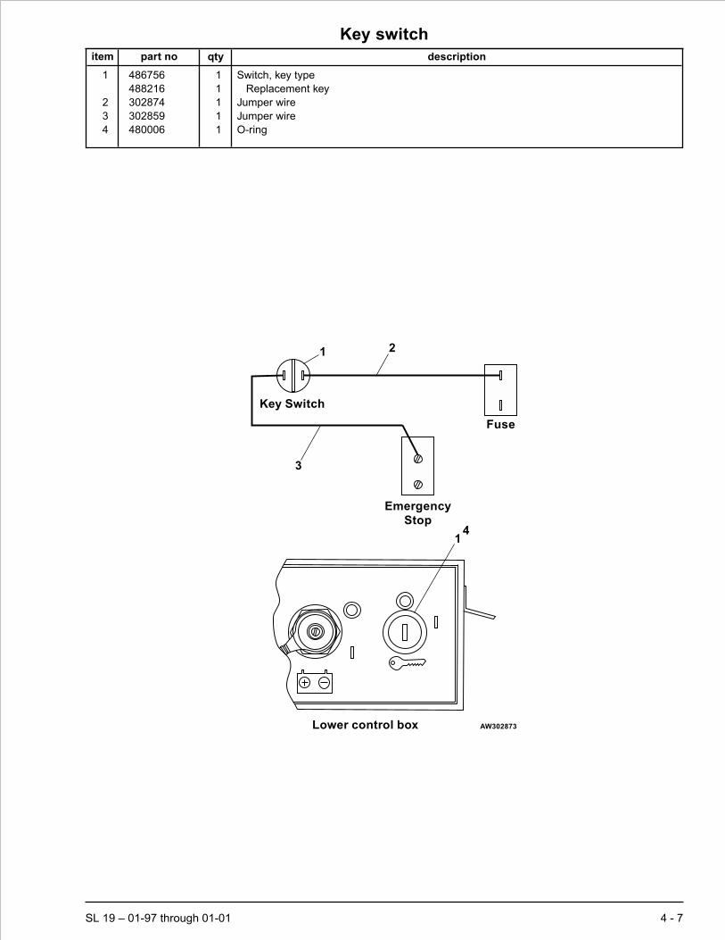
Key switch
item part no qty description
1 486756 1 Switch, key type
488216 1 Replacement key
2 302874 1 Jumper wire
3 302859 1 Jumper wire
4 480006 1 O-ring
SL 19 – 01-97 through 01-01 4 - 7
Lower control box
14
Fuse
Key Switch
Emergency
Stop
1 2
3
AW302873

Operator horn
item part no qty description
1 560332 1 Switch, push button
2 3040341 1 Pin, contact
3 960359 1 Terminal, #6 spade 18-14 wire
4 964749 1 Wire, 16 gauge single conductor x 30 inch long
5 0071269 1 Placard, horn
4 - 8 SL 19 – 01-97 through 01-01
1
2
2
1 5 23
4
34
Upper control box AW302850-2

Platform entry gate, automatic closing
item part no qty description
1 301514 1 Platform entry gate
2 970099 15 Capscrew 1/4-20 x 5/8 inch long hex head grade 5
3 987099 14 Washer 1/4 medium lock
4 479824 2 Spring hinge
5 984529 15 Nut sert 1/4-20
6 468886 2 End cap, 1-1/2 inch square plastic
7 300891 1 Door latch
8 300899 1 Latch stop
9 986019 3 Washer 1/4 medium flat
10 986269 2 Washer 5/16 medium flat
11 984539 2 Nut sert 3/8-16
12 970519 2 Capscrew 3/8-16 x 2-1/4 inch long hex head grade 5
13 987109 2 Washer 5/16 medium lock
14 301522 1 Tube
SL 19 – 01-97 through 01-01 4 - 9
A
A
23
5
4
1
1011
1213
14
Section A–A
B
B 7
259
8
23
59
View B-B
6
AW301517


index
BBase frame, 1-2Base frame cover, front, 1-24Battery cable, 1-4Battery cable, quick disconnect, 1-10Battery cable, standard, 1-10Battery charger, standard, 1-10Battery charger, standard - Lester, 3-10Battery charger, world, 1-10Battery charger, world - Lester, 3-10Battery tray, 1-14Battery wire, 1-10Battery, 6 volt DC - 220 amp hour, 1-14Bearing hub, 1-4, 1-9Bracket, battery tray, 1-14Bracket, bleed down, 1-16, 1-19Bracket, brake cylinder, 1-2Bracket, contactor, 3-5Bracket, power plate, 3-2, 3-5Bracket, stabilizer, 1-2Bracket, stabilizer return, 1-2Brake cylinder cover, 1-24Brake pin, left hand, 1-3Brake pin, right hand, 1-2Bus bar, 3-2, 3-5
CCartridge valve, manual pull, 1-19Circuit breaker, 5 amp thermal, 3-2, 3-5Contact block, emergency stop switch, 3-6, 3-9Contactor, 24 volt DC, 3-5Control valve, main, 1-10, 2-2Controller, upper control box, 3-9, 3-11Corrosion inhibitor, 3-2, 3-5, 3-6, 3-9Cover plate, 1-24Cover, electrical outlet, 4-2Cover, platform cable, 1-20Cylinder, brake, 1-3, 2-6, 2-7, 2-8Cylinder, cushion, 1-3, 2-9Cylinder, lift, 1-19, 2-10, 2-11Cylinder, steering, 1-2
DDecal set, valve, 2-2Decal, 125 volt 15 amp power to platform, 4-2Decal, attach fall restraint, 4-5Decal, battery charge, 1-23Decal, caution cylinder disassembly, 1-23Decal, check battery before charging, 1-23Decal, danger cylinder failure, 1-23Decal, danger safety prop, 1-23Decal, danger shearing/crushing, 1-23Decal, danger tipover hazard, 1-23Decal, danger tipover/electrical hazard, 1-23Decal, danger towing instructions, 1-23Decal, emergency stop, 1-23Decal, fork lift here, 1-23Decal, hydraulic fluid level, 1-23Decal, hydraulic oil level, 1-23Decal, hydraulic schematic, 1-23Decal, lower control schematic, 1-23Decal, lube recommendations, 1-23Decal, made in USA, 1-23Decal, OmniQuip logo, 1-23Decal, operating manual enclosed, 1-23Decal, SL 19 logo, 1-23Decal, Snorkel brand logo, 1-23Decal, Snorkel logo, 1-23
Decal, warning stripes, 1-23Diagnostic nipple, 2-2Door latch, 4-9Dust cap, 1-9
EElectric motor - 24 volt DC, 1-4, 3-12, 3-13Electrical hazard
See inside front coverElectrical outlet, GFCI - 20 amp capacity, 4-2Emergency power switch, 3-6, 3-9Engine mount washer, 1-3Entry chain gate, 1-20
FFlashing light, blue, 4-6Flashing light, yellow, 4-6Fuse block, 3-2, 3-5Fuse, 250 amp capacity, 3-2, 3-5
GGauge, battery condition indicator, 4-4Gear pump, 1-4Ground strap, 1-23Guard, emergency stop switch, 3-2, 3-5Guard, flashing light, 4-6
HHour meter, 3-2, 3-5Hub, 1-4Hub , 1-9Hydraulic drive motor, 1-3, 2-14, 2-16Hydraulic oil reservoir, 1-2Hydraulic tray, 1-10
IInsulator boot, 1-4, 1-10, 1-14
JJoystick controller, 3-6
LLanyard, 1-3Level sensor, 1-2, 1-16Lift cylinder cartridge valve, 1-16, 2-13Literature compartment, 1-23Lower control box, 1-10, 3-2, 3-5
MManifold valve, 2-2, 2-4Manual bleed down cartridge valve, 2-4
PPin lock, 1-2Pin, platform pivot, 1-16Pin, slider base, 1-16Placard, ANSI standard, 1-23Placard, caution serial number, 1-23Placard, danger do not alter switch, 1-23Placard, emergency bleed down valve, 1-23Placard, horn, 4-8Placard, lower control box, 1-23, 3-2, 3-5Placard, upper control box, 1-23, 3-6, 3-9Plate, battery hold down, 1-14Platform control cable, 1-10, 3-14Platform entry gate, 4-9
SL 19 – 01-97 through 01-01 index 1

Printed circuit board, lower control box, 3-2, 3-5Proximity switch, 1-3, 3-15
SScissor arm stack, 1-16, 1-19Sensor mount, 1-2Slider block, base frame, 1-16Slider block, platform, 1-16Spacer, air cleaner, 1-4Spacer, brake disc, 1-4Speaker, 3-5Spindle, left hand, 1-2Spindle, right hand, 1-2Stabilizer link, 1-2Stabilizer, skid - left hand, 1-2Stabilizer, skid - right hand, 1-2Steering connector link, 1-2Switch, battery disconnect, 3-2, 3-5Switch, key type, 4-7Switch, push button, 4-8Switch, toggle, 3-2, 3-5, 3-6, 3-9
TTire, non-marking, 1-2
UUpper control box, 3-6, 3-9
WWarranty
See inside back coverWire harness, flashing light, 4-6Wire harness, lower control box internal, 3-2, 3-5Wire harness, main, 1-10, 3-16Wire harness, motion lights, 4-6Wire harness, upper control box internal, 3-6, 3-9
index 2 SL 19 – 01-97 through 01-01
Index

LIMITED WARRANTY
Snorkel warrants each new machine manufactured and sold by it to be free from defects in material and workmanship for aperiod of one (1) year from date of delivery to a Customer or for one year after the machine has been placed in first service in aDealer rental fleet, whichever comes first.Any part or parts which, upon examination by the Snorkel Service Department, arefound to be defective, will be replaced or repaired, at the sole discretion of Snorkel, through its local Authorized Dealer at nocharge.
Snorkel further warrants the structural components; specifically, the mainframe chassis, turntable, booms and scissor arms,of each new machine manufactured by it to be free from defects in material and workmanship for an additional period of four(4) years. Any such part or parts which, upon examination by the Snorkel Service Department, are found to be defective willbe replaced or repaired by Snorkel through its local Authorized Dealer at no charge;however, any labor charges incurred as aresult of such replacement or repair will be the responsibility of the Customer or Dealer.
The Snorkel Service Department must be notified within forty-eight (48) hours of any possible warranty situation during theapplicable warranty period. Personnel performing warranty repair or replacement must obtain specific approval by SnorkelService Department prior to performing any warranty repair or replacement.
Customer and Dealer shall not be entitled to the benefits of this warranty and Snorkel shall have no obligations hereunderunless the “Pre-Delivery and Inspection Report” has been properly completed and returned to the Snorkel ServiceDepartment within ten (10) days after delivery of the Snorkel product to Customer or Dealer’s rental fleet. Snorkel must benotified, in writing, within ten (10) days, of any machine sold to a Customer from a Dealer’s rental fleet during the warrantyperiod.
At the direction of the Snorkel Service Department, any component part(s) of Snorkel products to be replaced or repairedunder this warranty program must be returned freight prepaid to the Snorkel Service Department for inspection. All warrantyreplacement parts will be shipped freight prepaid (standard ground) from the Snorkel Service Department or from Snorkel’sVendor to Dealer or Customer.
REPLACEMENT PARTS WARRANTY
Any replacement or service part made or sold by Snorkel is not subject to the preceding Limited Warranty beyond thenormal warranty period of the machine upon which the part was installed.
THIS WARRANTY EXCLUDES AND SNORKEL DOES NOT WARRANT:
1. Engines, motors, tires and batteries which are manufactured by suppliers to Snorkel, who furnish their own warranty.Snorkel will, however, to the extent permitted, pass through any such warranty protection to the Customer or Dealer.
2. Any Snorkel product which has been modified or altered outside Snorkel’s factory without Snorkel’s written approval, ifsuch modification or alteration, in the sole judgment of Snorkel’s Engineering and/or Service Departments, adverselyaffects the stability, reliability or service life of the Snorkel product or any component thereof.
3. Any Snorkel product which has been subject to misuse, improper maintenance or accident. “Misuse” includes but is notlimited to operation beyond the factory-rated load capacity and speeds. “Improper maintenance” includes but is notlimited to failure to follow the recommendationscontained in the Snorkel Operation,Maintenance, RepairParts Manuals.Snorkel is not responsible for normal maintenance, service adjustments and replacements, including but not limited tohydraulic fluid, filters and lubrication.
4. Normal wear of any Snorkel component part(s). Normal wear of component parts may vary with the type application ortype of environment in which the machine may be used; such as, but not limited to sandblasting applications.
5. Any Snorkel product that has come in direct contact with any chemical or abrasive material.
6. Incidental or consequential expenses, losses, or damages related to any part or equipment failure, including but notlimited to freight cost to transport the machine to a repair facility, downtime of the machine, lost time for workers, lostorders, lost rental revenue, lost profits or increased cost.
This warranty is expressly in lieu of all other warranties, representations or liabilities of Snorkel, either expressed or implied,unless otherwise amended in writing by Snorkel’s President, Vice President-Engineering, Vice President-Sales or VicePresident-Marketing.
SNORKEL MAKES NO WARRANTIES WHICH EXTEND BEYOND THE DESCRIPTION OF THIS LIMITED WARRANTY.SNORKEL MAKES NO IMPLIED WARRANTY OF MERCHANTABILITY OR FITNESS FOR A PARTICULAR PURPOSEAND DISCLAIMS ALL LIABILITY FOR INCIDENTAL OR CONSEQUENTIAL DAMAGES, INCLUDING BUT NOTLIMITED TO INJURY TO PERSONS OR PROPERTY.
The Customer shall make all warranty claims through its local Authorized Dealer and should contact the Dealer from whomthe Snorkel product was purchased for warranty service. Or, if unable to contact the Dealer, contact the Snorkel ServiceDepartment for further assistance.
Effective July 1995


SL 19 – revised December 2001 1
Maintenance and schematics
Maintenance informationThe parts drawings located in the repair parts sections,are designed for use as a guide for proper disassemblyof the machine and components as well as for parts re-placement.Always refer to the hydraulic system installa-tion drawings and the electrical wiring diagram beforeremoving or disassembling associated parts.
Do not attempt to disconnect or remove any hydrau-lic line before reading and understanding all textconcerning the system hydraulics. In most cases,disassembly of the machine will be obvious from theillustration.
When disassembling or reassembling components,complete the procedural steps in sequence. Do not par-tially disassemble or assemble one part, then start onanother. Always check your work to assure that nothinghas been overlooked.
The following list is a gentle reminder when disassem-bling or assembling the machine.
ü Always be conscious of weight.
ü Never attempt to lift heavy objects without the aid ofa mechanical device.
ü Do not allow heavy objects to rest in an unstablecondition.
ü Always make sure work platform is in stowedposition - blocked or the weight removed by asuitable lifting device before disconnecting thehydraulic hose from the motor/pump unit to the liftcylinder.
üWhen raising a portion of the machine, be sure thatadequate blocking is properly positioned - Do notdepend on lifting device to hold and secure weight.
ü If a part resists removal, check to see if allfasteners, electrical wiring, hydraulic lines, etc.,have been removed or that other parts are notinterfering.
Parts should be thoroughly inspected before restoring toservice at the time of reassembly. Burrs, nicks orscratches may be removed from machined surfaces byhoning or polishing with #600 crocus cloth, followed by athorough cleaning in an approved cleaning solvent, andblown dry with compressed air. Do not alter the contourof any part. If this operation does not restore the part to aserviceable condition, replace the part. Replace allO-rings, seals, and gaskets at reassembly. Use new rollpins or cotter pins. Dip all packing rings and seals in hy-draulic oil before reassembling in cylinder and manifoldinstallations.Replace any part having imperfect threads.In general, units that have been disassembled can bereassembled by reversing the order of disassembly.
Remember that the service life of a machine can be in-creased by keeping dirt and foreign materials out of thevital components. Precautions have been taken to safe-guard against this; shields, covers, seals and filters areprovided to keep air and oil supplies clean; however,these items must be maintained on a scheduled basis inorder to function properly.
At any time air or oil lines are disconnected, clean sur-rounding areas as well as the opening and fittings them-selves. As soon as a line or component is disconnected,cap or cover all openings to prevent the entry of dirt orforeign materials.
New parts should remain in their container until they areready to be used.
Clearly mark or tag hydraulic lines and electrical wiringconnections when disconnecting or removing them fromunit. This will assure that they are correctly reinstalled.
Proper assembly is critical to the successful rebuildingof any unit. Carefully inspect any parts which are to bereused. If in doubt, replace.
“SAFETY FIRST” is a good slogan.
Replace any guards and protective devices that havebeen removed to carry out maintenance and repairwork.
CAUTION

2 SL 19 – revised December 2001
Maintenance schedules
Snorkel has established a Preventive MaintenanceSchedule that includes Daily Maintenance (Operator'sInspection), 90 Day or 150 Hour (frequent) Maintenanceand Yearly or 500 Hour (annual) Maintenance, to detectany defective, damaged or improperly secured partsand provide information regarding lubrication and otherminor maintenance items.
The Maintenance Schedule following, outlines the re-quirements of these maintenance checks for each timeinterval. The Operator's Daily Maintenance and inspec-tion must be performed by a trained operator. All othermaintenance and inspections must be performed by atrained service technician only.
Note that the 90 Day or 150 hour (frequent) and yearly or500 hour (annual) Maintenance, require use of the Pre-ventive Inspection Maintenance Checklist to pinpoint allinspection items. Retain a copy of these forms for yourrecords.
They also require that all placards and decals on the unitare to be inspected.
All placards and decals must be in place and legible.Usethe placards installation drawing and parts listing in therepair parts section 1 of this manual to check these plac-ards and decals.
Snorkel recommends that you make additional copies ofthe Preventive Inspection Maintenance Checklist formsfor your use in performing these inspections.
Failure to perform the Preventive Maintenance atthe intervals outlined in the Maintenance Schedulemay result in a unit being operated with a defect thatcould result in INJURY or DEATH of the unit opera-tor. Do not allow a unit to be operated that has beenfound to be defective.
Repair all defects before returning the unit to service.
Daily maintenance - (operator’s inspection)
Components Service Required
Operator’s manual In document holder
Battery fluid level Proper level
Battery Terminals Clean, connections tight
Battery Charger Proper operation
Cables and wiring harness No wear or physical damage
Hydraulic fluid level Check fluid level
Hoses, tubes, and fittings No leaks
Free-wheeling valve Fully closed
Tires and wheels Good condition
Parking brakes Proper cam orientation
Operating controls Proper operation
Emergency stop Shuts off controls
Lowering alarm Proper operation
Pothole protector interlock Proper operation
Level sensor interlock Proper operation
Emergency lowering Proper operation
Safety bar No damage or deformation
Flashing light Proper operation
Weldments No damage or deformation
Guides, rollers, and slides Proper operation, no damage
Fasteners In place and tight
Guardrail system No damage or deformation
Platform extension Proper operation
Operating controls Proper operation
Emergency stop Shuts off upper controls
Lowering alarm Sounds when platform lowers
DANGER

SL 19 – revised December 2001 3
Maintenance schedules
Daily maintenance - (operator's inspection) continued
Components Service Required
Drive motion alarm Sounds when platform moves
Battery condition indicator Proper operation
Lanyard anchors No damage or deformation
Horn Sounds when activated
Electrical power outlet Proper operation
Placards and decals In place and readable
90 day or 150 hour maintenance - (trained service technician)
Components Service Required Recommended Lubricant orFurther Instructions
Daily maintenance Perform maintenance as per schedule
Preventive inspection mainte-nance checklist
Perform inspection, complete form Retain copy of checklist
Placards and decals inspection Inspect using drawing and parts listingin section 1 (repair parts)
Replace any missing or unread-able decals/placards
Door hinges and latches Lubricate SAE 10W oil or spray lubricant
Tie rods and king pinsSteer cylinder ends
Lubricate Conoco Super Sta #2Above 32° Mobilgrease CM-PBelow 32° Mobilgrease CM-L
Batteries Check specific gravity 1.260/1.275 at 80° F.
Platform lift capacity Check if platform can lift maximum load
Platform lift/lower speeds Check smooth operation and speeds
Hydraulic return filter Check condition Replace if dirty
Charging system Check operation
Platform controller Check smooth operation and speeds
Slide pads Check condition Do not lubricate
Scissor arm bearings Check condition Do not lubricate
Yearly or 500 hour maintenance - (trained service technician
Components Service Required Recommended Lubricant orFurther Instructions
90 day or 150 hour maintenance Perform maintenance per schedule
Hydraulic oil reservoir Clean and replace fluid Above 10° Mobil DTE-13MBelow 10° Mobil DTE-11M
Hydraulic return filter Replace After 1st. 50 hours, thereafterat recommended interval
Hydraulic pressures Check pressures
Platform controller Check operation
Base controls Check operation
Wheel bearings Clean and repack Conoco Super Sta #2Above 32° Mobilgrease CM-PBelow 32° Mobilgrease CM-L
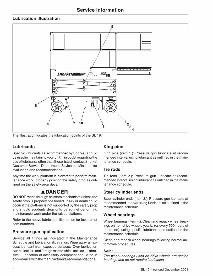
4 SL 19 – revised December 2001
Service information
Lubricants
Specific lubricants as recommended by Snorkel, shouldbe used in maintaining your unit. If in doubt regarding theuse of lubricants other than those listed, contact SnorkelCustomer Service Department, St. Joseph Missouri, forevaluation and recommendation.
Anytime the work platform is elevated to perform main-tenance work, properly position the safety prop as out-lined on the safety prop decal.
DO NOT reach through scissors mechanism unless thesafety prop is properly positioned. Injury or death couldoccur if the platform is not supported by the safety propand should suddenly drop onto personnel performingmaintenance work under the raised platform.
Refer to the above lubrication illustration for location ofitem numbers.
Pressure gun application
Service all fittings as indicated in the MaintenanceSchedule and lubrication illustration. Wipe away all ex-cess lubricant from exposed surfaces. Over lubricationcan collect dirt and foreign matter which acts as an abra-sive. Lubrication of accessory equipment should be inaccordance with the manufacturer’s recommendations.
King pins
King pins (item 1.): Pressure gun lubricate at recom-mended interval using lubricant as outlined in the main-tenance schedule.
Tie rods
Tie rods (item 2.): Pressure gun lubricate at recom-mended interval using lubricant as outlined in the main-tenance schedule.
Steer cylinder ends
Steer cylinder ends (item 3.): Pressure gun lubricate atrecommended interval using lubricant as outlined in themaintenance schedule.
Wheel bearings
Wheel bearings (item 4.): Clean and repack wheel bear-ings on non-drive wheels yearly, (or every 500 hours ofoperation), using specific lubricants and outlined in themaintenance schedule.
Clean and repack wheel bearings following normal au-tomotive procedures.
Note:The wheel bearings used on drive wheels are sealedbearings and do not require lubrication.
9
12
34
4 7 56
10
8
The illustration locates the lubrication points of the SL 19.
Lubrication illustration
DANGER

Service information
Hydraulic oil reservoir
Hydraulic oil reservoir (item 5.): The fluid level should bekept level with the indicator line of the side of the reser-voir and should be checked with all cylinders fully re-tracted and the platform in stowed position.
The interior of the reservoir should be wiped out andcleaned each time the hydraulic oil is changed. The res-ervoir filler/breather cap should be removed and the capbreather cleaned yearly with Kerosene, Fuel Oil, orother solvent.
Any time the hydraulic oil is changed or added, it is abso-lutely necessary that only clean hydraulic oil is used.
Note:If it becomes necessary to add or use an oil otherthan the recommended fluid, it is important that it becompatible and equivalent to the factory fill. Local oilsuppliers can generally furnish this information.
If questions still remain, contact Snorkel Customer Ser-vice Department, St. Joseph, Missouri, for further infor-mation.
Return filter
Return filter (item 6.): The hydraulic oil return filter ismounted in the right hand tray close to the hydraulic oilreservoir.
The filter element is a throwaway type filter and shouldbe changed after the initial break-in period (approxi-mately 50 hours operation time).
The filter condition should be checked at the 90 day or150 hour Preventive Inspection Maintenance interval ormore frequently under extreme working conditions.
When changing the filter element, the oil inside of the fil-ter element, should be examined for deposits of metalcuttings, which if present, could indicate excessive wearin some of the system components.
Door hinges and latches
Door hinges and latches (item 7.): Lubricate at recom-mended interval using specific lubricants as outlined inthe maintenance schedule.
After lubricating, remove any excess oil or over spray soit will not collect dirt and debris.
Slide pads
Slide pads (item 8.): Check slide pads for excessivewear and replace as required. Slide pads do not requirelubrication.
Scissor arm bearings
Scissor arm bearings (item 9.): Scissor arm bearingsare self lubricating. Check bearings for signs of damageand excessive wear as outlined in the maintenanceschedule. Do not lubricate scissor arm bearings.
Batteries
Batteries (item 10.): The batteries and battery cablesshould be checked to assure that the connections aretight and free of corrosion. Fluid level should be main-tained to assure that the batteries will maintain propercharge.
Check the batteries specific gravity per the maintenanceschedule.
The batteries are enclosed within a tray located on theside of the machine. For access to the batteries whenthe machine is lowered, position the machine on a hardlevel surface, unlatch and open tray.
Lead-acid batteries contain sulfuric acid which will dam-age eyes or skin on contact. When working around bat-teries, ALWAYS wear a face shield to avoid acid in eyes.If acid contacts eyes, flush immediately with clear waterand get medical attention.
Wear rubber gloves and protective clothing to keep acid offskin, if acid contacts skin, wash off immediately with clearwater.
Lead-acid batteries produce flammable and explosivegases. NEVER allow smoking, flames or sparks aroundbatteries.
SL 19 – revised December 2001 5
DANGER

Service information
Pothole protection interlock test1. Find a smooth flat, level concrete slab to park on in
order to avoid level sensor interlock action.
2. Remove all persons and materials from platform.
3. With platform fully lowered and swing-out traysclosed, check ground clearance under pothole pro-tector skids.Clearance should be over 1-1/2 incheson both sides of machine.
4. Using lower controls, raise the platform whilewatching movement of pothole protector skids.Skids should lower to less than 1 inch ground clear-ance, lift slightly as the linkage goes “over center”and then stop in “locked position” before platformfloor reaches 6 feet.
5. Using lower controls, fully lower the platform whilewatching movement of the pothole protector skids.Skids should lower slightly as the linkage goesback “over center” and then raise to their originalposition at over 2-1/2 inches ground clearance.
6. Place a 1-1/2 inch thick board (such as a standard2 x 4 lumber) under the right side pothole protectorskid to prevent it from lowering fully.
7. Using lower controls, raise the platform whilewatching the pothole protector. When the boardprevents the pothole protector skid from fully lower-ing to over center “locked”position, the pothole pro-tection interlock system should shut off raisemotion and sound an alarm at less than 6 feet plat-form floor height. The alarm should then soundwhenever the “UP” switch is activated and the plat-form should not lift any further.
8. Lower the platform and move the board to preventthe left side pothole protector skid from loweringfully.
9. Using lower controls, raise the platform whilewatching the pothole protector. When the boardprevents the pothole protector skid from fully lower-ing to over center “locked”position, the pothole pro-tection interlock system should shut off raisingmotion and sound an alarm at less than 6 feet plat-form floor height. The alarm should then soundwhenever the “UP” switch is activated and the plat-form should not lift any further.
If system does not operate properly, the machine mustbe repaired or adjusted by a trained service technicianbefore it can be used to elevate workers.
Level sensor interlock test1. First, test pothole protection interlock to verify
proper operation.
2. Lower platform to stowed position.
3. Remove all materials and persons from platform.
4. Find a level concrete slab to use as a test surface.Verify with a carpenters bubble level that the fourlocations where the machine’s tires will rest are in alevel plane within 1/8 inch between front and rearaxles, and within 1/16 inch between left and rightwheels on each axle.
5. Elevate front tires of machine 2-1/2 inches.
6. Using lower controls, raise the platform no morethan 9 feet platform floor height. The level sensorinterlock system should shut off raising motion andsound an alarm at less than 6 feet platform floorheight. The alarm should then sound whenever the“UP” switch is activated, and the platform shouldnot lift any further.
7. Repeat steps 5 and 6 above, elevating rear tires.
8. Elevate tires on right side of machine 3/4 inch.
9. Using lower controls, raise the platform to 9 feetplatform floor height. The level sensor interlocksystem should allow platform to be raised to 9 footfloor elevation. The system should not cut out plat-form raise function and should not sound an alarm.
10. Elevate tires on right side of machine 1-1/4 inches.
11. Using lower controls, raise the platform no morethan 9 feet platform floor height. The level sensorinterlock system should shut off raising motion andsound an alarm at less than 6 feet platform floorheight. The alarm should then sound whenever the“UP” switch is activated, and the platform shouldnot lift any further.
12. Repeat steps 8 through 11 above elevating tires onleft side of machine.
If system does not operate properly, the machine mustbe repaired or adjusted by a trained service technicianbefore it can be used to elevate workers.
6 SL 19 – revised December 2001
DANGER
DANGER

Service information
Battery care and maintenance
The following information about battery care and main-tenance was supplied by Interstate Batteries and is re-printed here with their permission.
1. New batteries need to be cycled several times be-fore reaching full capacity (20-50 cycles, depend-ing on type). Usage should be limited during thisperiod.
2. Always recharge batteries fully, immediately afteruse. Batteries perform best when they are fullycharged. More capacity and longer life will resultfrom this practice.
3. The deeper the discharge, the fewer number of cy-cles a lead-acid battery will deliver. Deep dis-charges deteriorate the battery quicker than lightershallow cycles.
4. Battery cables should be intact, and connectorskept tight at all times. Systematic inspection is rec-ommended.
5. Vent caps should be kept in place and tight duringvehicle operation and battery charging.
6. Batteries should be kept clean -- free of dirt andcorrosion -- at all times. Always keep the top of bat-teries clean. A film on top of the battery can causethe current to migrate between the posts, acceler-ating self discharge.
7. Never let the electrolyte level of a lead-acid batteryfall below the plates. Lack of maintaining the elec-trolyte in a lead-acid battery causes damage to theexposed portion of the plate which reduces capac-ity.
8. Always check electrolyte level before charging. Donot add water to individual cells unless plates areexposed. Batteries should be watered after charg-ing unless the plates are exposed before charging.If exposed before charging, the plates should becovered by approximately 1/8” of water. Check wa-ter level after charging. Water should be kept 1/4”below the bottom of the fill tube in the cell cover.
9. Water used to replenish batteries should be dis-tilled or treated to not exceed 200 T.D.S. (total dis-solved solids... parts per million). Particular careshould be taken to avoid metallic solids (iron).
10. A full charged battery will give you the best and lon-gest service.Be sure the batteries are fully chargedbefore testing or using. A fully charged battery,without a drain or load, after the surface charge hasdissipated, is 6.35 volts for a 6 volt battery.
11. Batteries should not be discharged below 20% of ca-pacity (approximately 1.8 volts per cell under normaloperating load; 1.98 volts open circuit; 1.145 specificgravity). Proper battery sizing will help avoid exces-sive discharge.
12. Battery chargers should be sized to fully charge bat-teries in an eight hour period. Chargers should bekept in proper operating condition.
13. Do not use a mismatched charger of any type; i.e.,a 12 volt charger on a 24 volt pack or a 24 voltcharger on a 12 volt pack. An undersized chargerwill never get the job done, no matter how long ittries. An oversized charger will cause excess gas-sing and heat that could possibly result in a batterymeltdown and/or explosion.
14. Never charge a lead-acid battery with a sealed (gelcell) battery charger. The lead-acid battery needshigher voltage to finish its charge. Without it thebattery will never come back to 100% and sulfationcan occur.
15. Always allow batteries to cool off after charging.The cooling time is very important because heat isgenerated during the recharge and discharge cy-cles. Without the cooling time the heat grows, ac-celerating grid corrosion which is one of the majorcauses of battery failure. Charging practice shouldenable batteries to cool before use.
16. Deep cycle batteries need to be equalized periodi-cally.Equalizing is an extended, low current chargeperformed after the normal charge cycle. It helpskeep cells in balance. Actively used batteriesshould be equalized once per week. Manuallytimed chargers should have the charge time ex-tended approximately 3 hours. Automatically con-trolled chargers should be unplugged andreconnected after completing a charge cycle.
17. In situations where multiple batteries are con-nected in series, parallel, or series-parallel, a re-placement battery's should be of the same size,age, and usage level as the companion batteries.Do not put a new battery in a pack that has 50 ormore cycles. Either replace all the batteries withnew batteries or install a good used battery's inplace of the bad. New batteries should be given afull charge before use.
18. Periodic battery testing is an important preventativemaintenance procedure. Hydrometer readings ofeach cell (fully charged) give and indication of balanceand true charge level.Imbalance could mean the needfor equalizing and is often a sign of improper chargingor a bad cell. Voltage checks (open circuit, chargedand discharged) can locate a bad cell or weak battery.Load testing will pick out a bad cell when other meth-ods fail. The point is to look for the abnormal. A weakcell or battery will cause premature failure of compan-ion cells or batteries respectively.
SL 19 – revised December 2001 7
6.30 volts = 93% charged6.27 volts = 89% charged6.25 volts = 85% charged6.22 volts = 80% charged6.10 volts = 50% charged5.94 volts = 20% charged

Service information
19. As batteries age, their maintenance requirementschange, Generally their specific gravity is higher andgassing voltage goes up. This means longer chargingtime and/or higher finish rate (higher amperage at theend of charge). Usually, older batteries need to be wa-tered more often and their capacity decreases.
20. “Opportunity charging”, a short partial charge during anextended duty cycle, is a controversial subject. Gen-erally, the practice is a “crutch” to make up for under-sized batteries. The correct approach is to installadequate battery capacity. If this is impossible becauseof lack of space in the battery compartment or extremeoperating conditions (24 hour intermittent use, as anexample), “opportunity charging” is better than exces-sive battery discharging. However, the practice cancause batteries to over heat, require more watering,and usually will shorten battery life. “Opportunity charg-ing” is a trade off; something to avoid if possible. Onecharging cycle per day is preferable.
21. Extreme temperatures can substantially affect bat-tery performance and charging. Cold reduces bat-tery capacity and retards charging. Heat increaseswater usage and can result in overcharging. Veryhigh temperature can cause “thermal run away”which may lead to and explosion or fire. If extremetemperature is an unavoidable part of an applica-tion, consult a battery/charger specialist aboutways to deal with the problem.
22. An overly discharged battery might need to be cy-cled a few times before it can recover fully. If a bat-tery begins to heat before coming up to a fullcharge, it might be necessary to discharge the bat-tery and recharge it a few times. The charge anddischarge cycle might help the current acceptanceof the battery and facilitate its recovery to a usablecondition.
23. Inactivity can be harmful to deep cycle batteries. Ifthey sit for several months, a “boost” charge shouldbe given -- more frequently in warm climate (aboutonce a month) than in cold (every 2-3 months).
24. Never store a battery in a discharged state.The sul-fate that forms during discharge can make the bat-tery impossible to recharge fully.
Battery charger
SL 19 units are equipped with an onboard automaticbattery charger. This charger has an electronic circuitthat will completely recharge the batteries and automati-cally turn off after the charge cycle is completed.
The charging cycle may last 1-1/2 to 16 hours depend-ing on the state of charge of the batteries. If the chargingcycle should exceed 16 hours without the batteries be-ing fully recharged, the charger should be shut off andthe batteries should be checked.
If the batteries show no signs of problems and the spe-cific gravity readings are within the range indicated pre-viously, then the charger should be checked.
General charging cautions1. Do not recharge batteries unless Electrolyte level
has been checked. Operate charger in accordancewith the battery charging instructions outline in thismanual. Place BATTERY DISCONNECT switch inthe “OFF” position before charging batteries.
2. Do not smoke or introduce a flame or spark in thecharging area.
Lead acid batteries generate highly explosive Hy-drogen gas, especially during charging cycle. Toavoid the possibility of an explosion, charge batter-ies only in a well ventilated area away form sparks orflame.
3. Use protective face and eye equipment whenchecking the condition of charging batteries.
8 SL 19 – revised December 2001
DANGER

SL 19 – revised December 2001 9
Preventive inspection maintenance
90 day or 150 hour checklist
OK OK - No Service Required Serial Number✔ Corrective Action RequiredX Corrected, (Record description of corrective action).
Inspection Procedures Codes(1) Weld cracks, dents and/or rust(2) Installation(3) Leaks(4) Operation(5) Condition(6) Tightness(7) Residue buildup(8) See placards and decals inspection chart
Check OK ✔ X
BaseframeStructural (1)Steering cylinder (2,3,4)Steering cylinder fasteners and linkage (1,2)Tires and wheels (5)Hydraulic tubes and hoses (3,5)Decals and placards (2,8)Cowling covers (5,6)Torque all wheel lug nuts/bolts per placard (2,6)Right drive motor (3,6)Left drive motor (3,6)Parking brakes (3,4)Free wheeling valve (4,6)Cords and wire assemblies (2,5)Pothole protector interlock and alarm (1,2,4)Level sensor interlock and alarm (4,5)Swing-out trays (2,4,5)Hydraulic oil reservoir (3,5)Filler cap (6)Hydraulic fluid level (2,5)Return filter (2,6)Oil level tube (3,4)
Scissor arm stackStructural (1)Scissor arm pivot pins, snap rings and roll pins (2,5)Lift cylinder and valves (2,3,4)Safety bar (2,4,5)Manual lowering valve (4)Hydraulic tubes and hoses (3,5)Wires and electrical cables (2,5)Decals and placards (2,8)
Lower controlsControl select switch “BASE”platform controls do not work (4)Control select switch “PLATFORM”base controls do not work (4)Toggle switch, lift UP - DOWN (4)Lowering alarm (4)Battery disconnect switch “OFF”controls do not work (4)Emergency stop switch “OFF”controls do not work (4)Hour meter (4)
Check OK ✔ X
PlatformStructural (1)Guardrails properly installed and fastened (2,5)Platform entry chain or gate (2,5)Wires and electrical cables (2,5)Decals and placards (2,8)Correct operators manual in document holderRoll-out extension deck (2,4,5,8)
Upper controlsControl select switch (4)DRIVE/STEERcontrol select switch activated on “DRIVE” (4)Speed switch, speed 1 - SLOW (4)Speed switch, speed 2 - MEDIUM (4)Speed switch, speed 3 - FAST (4)Platform elevated, drives slow only (4)Platform lowered, drives fast, medium or slow (4)Platform UP/DOWN switch, UP - DOWNcontrol select switch activated on “PLATFORM” (4)Emergency stop “OFF”no controls work (4)
ElectricalMotor and hydraulic pump assembly (2,4)Batteries (2,4)Battery terminals (5,6,7)Battery electrolyte level (5)Battery specific gravity reading (5)Wires and cables (2,5,6)Battery charger (2,4,5)
Optional equipmentPlatform entry gate, spring loaded (2,4,5)Battery condition indicator (2,4)AC 110 volt outlet on platform (2,4)Operator horn (2,4)Motion warning alarm (2,4)Flashing light (2,4)

10 SL 19 – revised December 2001
Preventive inspection maintenance
Corrective Action Required
Note: If correction action is required on any item, attach sheet indicating problem and action taken.
All items have been properly checked and tested and found to be operating satisfactory or necessary corrective action has been completed.
Inspected By: Date

Capscrew torque chart
SL 19 – revised December 2001 11
GRADE
BOLT
SAE GRADE
1 OR 2
SAE GRADE
5
SAE GRADE
6
SAE GRADE
8
MARKING
MIN. TENSILE
STRENGTH64,000 P.S.I. 105,000 P.S.I. 133,000 P.S.I. 150,000 P.S.I.
MATERIAL
DEFINITION
LOW
CARBON
STEEL
MEDIUM
CARBON
STEEL
TEMPERED
MEDIUM
CARBON
STEEL
Q & T
MED. CARBON
ALLOY
STEEL
Q & T
INDETERMINATE
QUALITY
MINIMUM
COMMERCIAL
QUALITY
MEDIUM
COMMERCIAL
QUALITY
BOLT SIZE
1/4
5/16
3/8
7/16
1/2
9/16
5/8
3/4
7/8
1
5
9
15
24
37
53
74
120
190
282
7
14
25
40
60
88
120
200
302
466
10
19
34
55
85
120
167
280
440
660
10.5
22
37
60
92
132
180
296
473
714
RECOMMENDED TORQUE VALUES (FT - LBS)
The following rules apply to the chart
1. Consult manufacturers' specific recommendations when available.
2. The chart may be used with both course and fine thread fasteners lightly lubricated.
3. Increase torque by 20% when multiple tapered tooth (shake proof) lock washers are used.
4. The torque values are given in foot-pounds.
5. Inch pound equivalent may be obtained by multiplying by 12.


Page 13
Hydraulic schematic
Snorkel model SL 19

Page 14
Wiring schematic
Snorkel model SL 19

Page 15
Logic diagramelectrical wiringSnorkel model SL 19
