repair parts manual - snorkellifts.com€¦ · repair parts manual p/n 302876 june 1998 - revised...
TRANSCRIPT

Repair PartsManual
P/N 302876June 1998 - revised December 2001
battery powered
electric
Manufactured 01-97 through 01-01

General information
© Snorkel – all rights reserved Printed in USA
DANGER
CAUTION
About this manual:This repair parts manual covers current production ma-chines only.
While Snorkel has attempted in every way to confirmthat all information in this manual is correct, improve-ments are being constantly made to the machine thatmay not be reflected in this manual.
If you find information in this manual that is not correct,or is confusing, you are urged to report your findings toSnorkel for our evaluation.
Your input is important to us and will be used in futureprintings of this manual.
Every person who repairs this machine must be quali-fied and authorized to do so.
DO NOT modify this aerial platform without priorwritten consent of Snorkel Engineering Depart-ment. Modification may void the warranty, ad-versely affect stability, or affect the operationalcharacteristics of the aerial platform.
This machine is covered by a limited warranty that spe-cifically identifies items warrantied by Snorkel and thoseitems covered by original manufacturers warranty.
A copy of the Snorkel Limited Warranty is located on theinside of the back cover of this manual.
All correspondence relative to this machine, such asfield reports, discrepancy reports, requests for informa-tion, etc., should be directed to:
Snorkel International, Inc.P.O. Box 1160St. Joseph, MO 64502-1160 USAPhone: (816)-364-0317
http://www.snorkelusa.com
AbbreviationsThe following abbreviations may be used in this manual:
AC. . . . . . . . . . . . . . . . . . . . . . . . . alternating currentANSI . . . . . . . American National Standards InstituteCCA. . . . . . . . . . . . . . . . . . . . . . . cold cranking ampscm. . . . . . . . . . . . . . . . . . . . . . . . . . . . . . . centimeterDC. . . . . . . . . . . . . . . . . . . . . . . . . . . . . direct currentEMS . . . . . . . . . . . . . envelope management systemGFCI . . . . . . . . . . . . . . . . ground fault circuit interruptLP . . . . . . . . . . . . . . . . . . . . . . . . . liquified petroleumLPG . . . . . . . . . . . . . . . . . . . . liquified petroleum gasmm . . . . . . . . . . . . . . . . . . . . . . . . . . . . . . millimetersft . . . . . . . . . . . . . . . . . . . . . . . . . . . . . . . . . . . . . feetin . . . . . . . . . . . . . . . . . . . . . . . . . . . . . . . . . . . . . inchlbs . . . . . . . . . . . . . . . . . . . . . . . . . . . . . . . . . poundsno . . . . . . . . . . . . . . . . . . . . . . . . . . . . . . . . . number
NPT . . . . . . . . . . . . . . . . . . . . . . national pipe threadpsi . . . . . . . . . . . . . . . . . . . . . pounds per square inchqty . . . . . . . . . . . . . . . . . . . . . . . . . . . . . . . . . quantityUL . . . . . . . . . . . . . . . Underwriters Laboratories Inc.
Electrical Hazard
The aerial platform is not electrically insulated.Death or serious injury can result from contact with,or inadequate clearance from, an energizedconductor.
Do not go closer than the minimum safe approachdistance as defined by the minimum Safe ApproachDistance as defined by ANSI Standards.
Regard all conductors as energized.
Allow for electrical wire sag and aerial platform sway.
If the work platform, or any part of the aerial platformcontacts a high-voltage electrical conductor, the entiremachine can become electrically charged.
If that happens, remain on the machine and do not con-tact any other structure or object. This includes theground, adjacent buildings, poles, and any other objectsthat are not part of the aerial platform.
Such contact could make your body a conductor to theother object, creating an electrical shock hazard result-ing in death or serious injury.
If an aerial platform is in contact with an energized con-ductor the platform operator must warn ground person-nel in the vicinity to stay away. Their bodies can conductelectricity creating an electrical shock hazard resultingin death or serious injury.
Do not approach or leave the aerial platform until theelectricity has been turned off.
Do not attempt to operate the lower controls when thework platform or any part of the aerial platform is in con-tact with a high-voltage electrical conductor or if there isan immediate danger of such contact.
Personnel on or near an aerial platform must be continu-ously aware of electrical hazards, recognizing thatdeath or serious injury can result from contact with anenergized conductor.

Table of contents
Service and parts informationTo order service or repair parts . . . . . . . . . . . . . . . . . . iANSI and OSHA compliance . . . . . . . . . . . . . . . . . . . . iManuals . . . . . . . . . . . . . . . . . . . . . . . . . . . . . . . . . . . iParts order form . . . . . . . . . . . . . . . . . . . . . . . . . . . . . ii
Section 1. - Repair partsBase frame . . . . . . . . . . . . . . . . . . . . . . . . . . . . . . . 1-2Bearing hub . . . . . . . . . . . . . . . . . . . . . . . . . . . . . . . 1-7Hydraulic tray . . . . . . . . . . . . . . . . . . . . . . . . . . . . . 1-9Battery tray . . . . . . . . . . . . . . . . . . . . . . . . . . . . . . 1-15Scissor arms mounting . . . . . . . . . . . . . . . . . . . . . 1-16Scissor arm stack . . . . . . . . . . . . . . . . . . . . . . . . . 1-20Platform, fixed rails . . . . . . . . . . . . . . . . . . . . . . . . 1-22Platform, folding rails. . . . . . . . . . . . . . . . . . . . . . . 1-25Placards, decals and covers . . . . . . . . . . . . . . . . . 1-30
Section 2. - HydraulicsControl valve, main . . . . . . . . . . . . . . . . . . . . . . . . . 2-2Manifold valve . . . . . . . . . . . . . . . . . . . . . . . . . . . . . 2-4Cylinder, brake - Green . . . . . . . . . . . . . . . . . . . . . . 2-6Cylinder, brake - Prince. . . . . . . . . . . . . . . . . . . . . . 2-7Cylinder, brake - Rosenboom . . . . . . . . . . . . . . . . . 2-8Cylinder, lift - GBI . . . . . . . . . . . . . . . . . . . . . . . . . . 2-9Cylinder, lift - Texas . . . . . . . . . . . . . . . . . . . . . . . . 2-10Cylinder, steering - Green . . . . . . . . . . . . . . . . . . . 2-11Cylinder, steering - Rosenboom . . . . . . . . . . . . . . 2-12Hydraulic drive motor - Ross. . . . . . . . . . . . . . . . . 2-13Hydraulic drive motor - White . . . . . . . . . . . . . . . . 2-14Lift cylinder cartridge valve . . . . . . . . . . . . . . . . . . 2-15Relief/check valve . . . . . . . . . . . . . . . . . . . . . . . . . 2-16
Section 3. - ElectricalLower control box before 3-1-99 . . . . . . . . . . . . . . . 3-2Lower control box after 3-1-99 . . . . . . . . . . . . . . . . 3-5Upper control box before 12-6-99 . . . . . . . . . . . . . . 3-6Upper control box after 12-6-99 . . . . . . . . . . . . . . . 3-9AC outlet on platform . . . . . . . . . . . . . . . . . . . . . . 3-10Battery charger . . . . . . . . . . . . . . . . . . . . . . . . . . . 3-11Controller, upper control box . . . . . . . . . . . . . . . . . 3-12DC electric motor, Leeson. . . . . . . . . . . . . . . . . . . 3-13DC electric motor, Ohio . . . . . . . . . . . . . . . . . . . . . 3-14Platform control cable . . . . . . . . . . . . . . . . . . . . . . 3-15Proximity switch. . . . . . . . . . . . . . . . . . . . . . . . . . . 3-16Wire harness, main . . . . . . . . . . . . . . . . . . . . . . . . 3-17
Section 4. - Factory installed optionsAC generator . . . . . . . . . . . . . . . . . . . . . . . . . . . . . . 4-2Air line to platform . . . . . . . . . . . . . . . . . . . . . . . . . . 4-3Battery condition indicator. . . . . . . . . . . . . . . . . . . . 4-4Dual lanyard attachment . . . . . . . . . . . . . . . . . . . . . 4-5Dual flashing lights . . . . . . . . . . . . . . . . . . . . . . . . . 4-6Flashing light . . . . . . . . . . . . . . . . . . . . . . . . . . . . . . 4-8Key switch . . . . . . . . . . . . . . . . . . . . . . . . . . . . . . . . 4-9Lift alarm . . . . . . . . . . . . . . . . . . . . . . . . . . . . . . . . 4-10
Operator horn . . . . . . . . . . . . . . . . . . . . . . . . . . . . 4-11Overload alarm . . . . . . . . . . . . . . . . . . . . . . . . . . . 4-12Platform entry gate, fixed rails . . . . . . . . . . . . . . . 4-13Platform entry gate, folding rails . . . . . . . . . . . . . . 4-14Scissor guarding . . . . . . . . . . . . . . . . . . . . . . . . . . 4-15Spare battery tray . . . . . . . . . . . . . . . . . . . . . . . . . 4-16
SL 25 – 01-97 through 01-01


Service and parts information
To order service or repair partsWhen placing an order for service or repair parts, pleasehave the following information available for your ma-chine.
� Machine model number
� Machine serial number
� Snorkel part number
� Description of part
� Quantity of parts required
� Your purchase order number
� Address for order to “Ship To”
� Your desired shipment method
The parts order form on the following page may bemailed or faxed to the attention of Parts Worldwide at thefollowing location:
Snorkel International, Inc.P.O. Box 1160St. Joseph, MO 64502-1160 USA
Phone: 1-(800)-255-0317Parts Worldwide Fax: (816)-364-6312
Attention: Parts Department
For your convenience, our electronic on-line orderingsystem is available at the following Internet location:
http://www.omniquip.com
ANSI and OSHA complianceAll owners and users of the aerial platform must read,understand, and comply with all applicable regulations.Ultimate compliance to OSHA regulations is the respon-sibility of the user and their employer.
ANSI publications clearly identify the responsibilities ofall personnel who may be involved with the aerial plat-form. A reprint of the “Manual of Responsibilities forDealers, Owners, Users, Operators, Lessors and Les-sees of ANSI/SIA A92.5-1992 Boom-Supported Ele-vating Work Platforms” is available from Snorkel dealersor from the factory upon request.
Copies are also available from:
Scaffold Industry Association20335 Ventura Blvd. Suite 310Woodland Hills, CA 91364-2471 USA
ManualsManuals are available from Snorkel to support any of themachines that we produce.
The specific manuals for SL 25 are as follows:
� Operator’s ManualSnorkel part number - 302875
� Repair Parts ManualSnorkel part number - 302876
� Troubleshooting GuideSnorkel part number - 302988
� ANSI Manual of ResponsibilitiesANSI/SIA A92.6-1990
SL 25 – 01-97 through 01-01 i
Record machine information here:
Model number
Serial number
Date of purchase
Purchased from
Snorkel dealer or distributor

ii SL 25 – 01-97 through 01-01
Parts order form
Fill out completely and fax to (816)-364-6312 attention: Parts Worldwide
Address
Contact name
Phone number
Fax number
Account number
Purchase order number
Company
Date
Purchase order number
Model
Serial number
Optional equipment
Ship to
Ship by
Part number Description Quantity Price
Backordered parts will be shipped as soon as available by the same shipping methodas the original order unless indicated below:
Note:
Ship complete order only - do not backorder parts.
Ship all available parts and supply information of disposition of backordered parts.
Other instructions as specified

Section 1. - Repair parts
SL 25 – 01-97 through 01-01 1 - 1

Base frameitem part no qty description
1 986389 2 Washer special .765 inch flat2 5569941 4 Machine bushing 7/8 inch OD x 1/2 inch ID x 14 gauge thick3 984459 10 Lug nut 1/2-20 hex 60°4 5076116 2 Adapter5 604076 4 Thrust bearing6 590984 2 Cylinder, brake
(see page 2-6 for Green cylinder)(see page 2-7 for Prince cylinder)(see page 2-8 for Rosenboom cylinder)
7 561196 2 Bearing8 5570008 1 Air vent9 5090034 1 Hose guard x 12 inches long
10 3011403 1 Cable 14 gauge/3 conductor x 570 inches long11 5093001 4 Clamp12 5560082 1 Trim lock, 1/4 inch x 28 inches long13 25560083 1 Trim lock x 12 inches long14 5093013 4 Clamp15 302536 1 Step16 5093006 1 Clamp17 5093002 4 Clamp18 5074404 1 Bulkhead locknut19 5065728 4 Straight thread adapter20 302802 1 Proximity switch - (see page 3-16 for parts breakdown)21 5065705 2 Straight thread adapter22 970969 1 Capscrew 1/2-13 x 3 inch long hex head grade 523 302624 1 Spacer24 5036803 1 Swivel nut branch tee25 5569940 1 Washer 1-1/2 OD x 1 ID x 1/16 inch thick26 0150224 4 Clamp bar27 5035303 3 Straight thread 90° elbow28 5034404 4 Bulkhead union29 984089 2 Nut 5/16-18 hex30 5065703 1 Straight thread adapter31 472326 2 Clevis pin 1/2 inch diameter x 1-1/8 inch grip32 465276 2 Clevis pin 1/2 inch diameter x 1-9/32 inch grip33 0151470 1 1/2 inch hydraulic tube34 411226 4 Bearing35 302434 2 1/2 inch hydraulic hose36 302433 2 1/2 inch hydraulic hose37 302766 1 Support38 302431 2 Slide pad39 988129 2 Cotter pin 5/32 inch diameter x 1-3/4 inch long40 302428 8 Spacer, stabilizer41 302427 4 Spring, stabilizer42 302423 2 Guard, stabilizer43 302574 2 Lanyard44 970269 2 Capscrew 5/16-18 x 1-1/4 inch long hex head grade 545 5560031 4 Nut 5/16-18 self locking46 984109 6 Nut 3/8-16 hex47 302362 4 Block, stabilizer cross shaft48 302361 4 Block, stabilizer cross shaft49 302302 2 Hydraulic drive motor - (see page 2-13 for parts breakdown)50 302284 2 Bracket, tray latch catch
Parts list continued on next page
1 - 2 SL 25 – 01-97 through 01-01

Base frameitem part no qty description
51 302269 2 Hub52 5569938 10 Capscrew 1/2-20 x 2-1/4 inch long hex head grade 5 full thread53 302797 1 Stabilizer x-shaft, front54 302798 1 Stabilizer x-shaft, rear55 302252 1 Bracket, stabilizer56 302248 4 Pin, headless 1/2 inch diameter x 1-1/4 inch long57 972449 4 Capscrew 3/8-16 x 3/4 inch long socket flat head58 302245 2 Link, stabilizer x-shaft59 0360124 1 Pothole protection linkage60 302243 2 Stabilizer skid61 302238 4 Bracket, angle return spring62 302236 8 Link half, stabilizer foot63 302234 4 Block, stabilizer foot64 302233 4 Stabilizer foot65 302232 1 Steering spindle, left hand - (before 3-10-98)
0360507 1 Steering spindle, left hand - (from 3-10-98 to 8-10-98)0360742 1 Steering spindle, left hand - (after 8-10-98)
66 302231 1 Steering spindle, right hand - (before 3-10-98)0360508 1 Steering spindle, right hand - (from 3-10-98 to 8-10-98)0360744 1 Steering spindle, right hand - (after 8-10-98)
67 302229 2 Pin cap, steering68 302550 1 Link, steering connector right half - (before 3-3-98, requires left half also)
302553 1 Link, steering connector left half - (before 3-3-98, requires right half also)0360504 1 Link, steering connector - (after 3-3-98)
69 302779 1 Base frame70 301480 2 Bearing hub - (see page 1-7 for parts breakdown)71 301277 4 Shoulder bolt 3/8-16 x 1-1/4 inch long72 301464 2 Brake disc73 301443 2 Swivel long 90°74 301442 2 Swivel short 90°75 301406 2 Pin tray adjuster76 8070320 2 Cotter pin 1/8 inch diameter x 1-1/2 inch long77 301402 4 Bearing, flanged78 301341 2 Bracket, brake cylinder79 301286 1 Stabilizer shaft spring80 302625 1 Stabilizer roller81 5569939 2 Washer 2 inch OD x 1-1/16 inch ID x 1/8 inch thick82 300928 1 Brake pin, left hand83 300927 1 Brake pin, right hand84 300778 9 Locknut, centerlock85 300769 8 Connector link half86 302800 1 Level sensor, 2 axis - 2° and 4°87 300729 10 Capscrew, special88 5560354 9 Carriage bolt 1/2-13 x 1-1/2 inch long89 300395 4 Bearing90 300393 2 Pin
Parts list continued on next page
SL 25 – 01-97 through 01-01 1 - 3

Base frameitem part no qty description
91 0360794 4 Clevis pin92 300368 1 Cylinder, steering - (see page 2-11 for Green cylinder)
6047080-99 1 Cylinder, steering - (see page 2-12 for Rosenboom cylinder)93 302984 4 Bearing94 300354 2 Thrust washer95 300351 5 Bearing96 2593404 8 Bearing97 2590711 10 Bushing98 2501616 4 Bearing99 970489 2 Capscrew 3/8-16 x 1-1/2 inch long hex head grade 5
100 972439 11 Carriage bolt 3/8-16 x 1-1/4 inch long101 970049 2 Capscrew 1/4-20 x 1 inch long hex head grade 5102 5560354 9 Carriage bolt 1/2-13 x 1-1/2 inch long103 971069 8 Capscrew 1/2-13 x 2-3/4 inch long hex head grade 5104 970469 9 Capscrew 3/8-16 x 1 inch long hex head grade 5105 5569934 2 Set screw 1/4-20 x 3/8 inch long hex socket flat point106 970369 2 Capscrew 5/16-18 x 1 inch long hex head grade 5107 5569819 2 Capscrew, special serrated head108 5561557 2 Capscrew 3/4-10 x 3 inch long hex head grade 5109 970449 4 Capscrew 3/8-16 x 3/4 inch long hex head grade 5110 970459 8 Capscrew 3/8-16 x 7/8 inch long hex head grade 5111 970479 10 Capscrew 3/8-16 x 1-1/4 inch long hex head grade 5112 5569933 2 Washer .531 medium flat113 968379 2 Snap ring114 970949 2 Capscrew 1/2-13 x 2-1/2 inch long hex head grade 5115 5560039 13 Nut 1/2-13 self locking116 488176 4 Tire, solid non-marking 5 x 8 white117 5560004 7 Nut 1/4-20 self locking118 5560033 41 Nut 3/8-16 self locking119 5560586 1 Washer 3/8 star tooth lock120 986269 37 Washer 5/16 medium flat121 986459 2 Washer 3/4 medium flat122 986019 7 Washer 1/4 medium flat123 986359 9 Washer 1/2 medium flat124 986299 1 Washer 3/8 medium flat125 989689 8 Roll pin 1/4 inch diameter x 2-3/4 inch long126 989739 2 Roll pin 1/4 inch diameter x 1 inch long127 5560056 4 Roll pin 1/8 inch diameter x 1 inch long128 987119 16 Washer 3/8 medium lock129 989379 4 Roll pin 1/8 inch diameter x 1-1/4 inch long130 972589 4 Carriage bolt 1/4-20 x 1 inch long131 5560350 13 Carriage bolt 3/8-16 x 1 inch long132 5560531 4 Carriage bolt 3/8-16 x 1-1/2 inch long
1 - 4 SL 25 – 01-97 through 01-01

Page 1 - 5
Base framesheet 1Snorkel model SL 25
VIEW A-A
17
26
124118
104
11131
120118
10 100
120118
14
FF
E
E
120
D
D
CCJJ
H
H
A
A
12
14
52
52
120118
100
118100 37
69
DETAIL M-M
NN
M
M
(LH)(RH SHOWN)65
66
19
19
74
73
46132
DETAIL K-K
SECTION J-J
VIEW H-H
86
93104128
87
136
116
51
49
35 3592
2818
795127
31
2736
103115
67
113
112
77
SEE DETAIL K-K
68
7076
81
352
2783126
2430
3484
32127
82 6
84
15
118100
118100
78
102
AW302334-1

Page 1 - 6
Base framesheet 2Snorkel model SL 25
SECTION R-R
LIFT TANKHOSE BATTERY CABLES
STEER HOSES
VIEW B-B
FWD
REVGROUND WIRESFROM MAINHARNESS
GNDLS
GNDBX
GNDDN
R
R
SECTION F-F
G
G
SECTION G-G
SECTION E-E
SECTION D-D
SECTION C-C
B
B
118124
9959
8023
22115123
79
55
54
101117
122
20
81114
115
123
58
59
9097
129
12
53
108121
105
42
1610775
33
2223
25
60 118131
61
130122117
14
42
96712
1412
41
9740
111118120
11111812046
47
48
98
110120
128
85
62
578488 89
91129
38
60106
45
12043
4429
45120
102118
119
109 120 12850
5 25
63
64
125
9556
54
AW302334-3
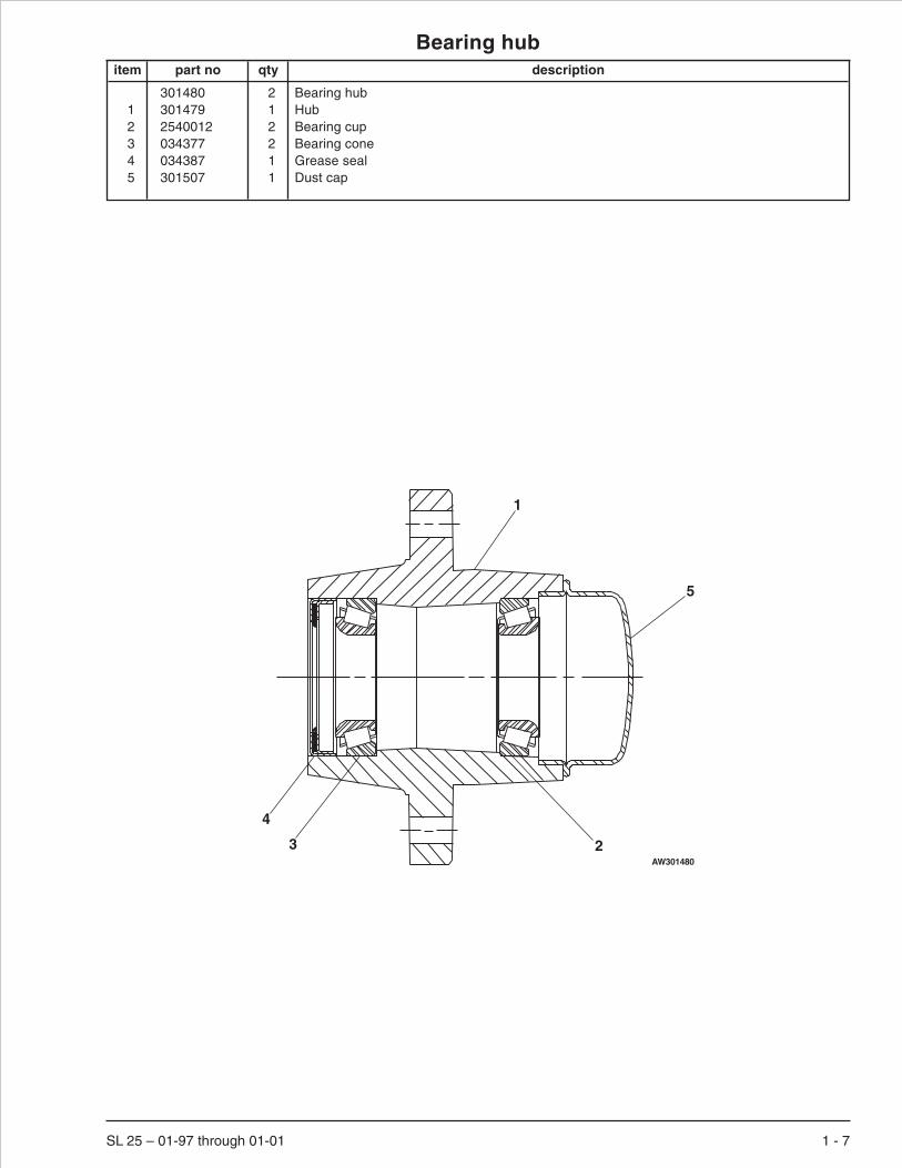
Bearing hubitem part no qty description
301480 2 Bearing hub1 301479 1 Hub2 2540012 2 Bearing cup3 034377 2 Bearing cone4 034387 1 Grease seal5 301507 1 Dust cap
SL 25 – 01-97 through 01-01 1 - 7
1
23
4
5
AW301480


Hydraulic trayitem part no qty description
1 300437 2 Bearing flange2 300554 1 1/2 inch hydraulic tube3 301264 1 Spacer, stabilizer4 301440 1 Return filter
451896 1 Replacement filter element5 302257 1 Tray latch torsion spring6 302285 1 Channel, tray latch7 302443 1 Control valve, main - (see page 2-2 for parts breakdown)8 302449 1 Suction tube9 302467 1 Relief/check valve - (see page 2-16 for parts breakdown)
10 302468 1 3/4 inch hydraulic tube11 302469 1 3/8 inch hydraulic tube12 302472 1 3/8 inch hydraulic tube13 0360877 1 Hydraulic oil reservoir14 5560097 6 Speed nut 5/16-1815 302748 1 Hydraulic tray16 302754 1 Pump mounting plate17 302755 1 Relief valve mounting bracket18 302762 1 3/8 inch hydraulic tube19 302764 1 Return tube, filter/tank20 302765 1 Cover, hydraulic oil reservoir21 302775 1 3/8 inch hydraulic tube22 5560033 8 Nut 3/8-16 self locking23 302934 1 Platform control cable - (see page 3-15 for replacement parts)24 302787 1 Wire harness, main - (see page 3-17 for parts breakdown)25 302977 1 Lower control box before 3-1-99 - (see page 3-2 for parts breakdown)
302986 1 Lower control box after 3-1-99 - (see page 3-5 for parts breakdown)26 302810 1 Gasket, 3/8 inch x 1 inch x 6 inch long27 3080046 2 Electric motor - 24 volt DC
(see page 3-13 for Leeson motor)(see page 3-14 for Ohio motor)
28 6020075 2 Hydraulic gear pump6091146 1 Seal repair kit, Parker pump8190112 1 Seal repair kit, Sundstrand pump
29 7190001 1 Gasket, weatherproof x 6 inches long30 5560031 2 Nut 5/16-18 self locking31 0240770 2 3/8 inch hydraulic hose - (standard machines)32 464004 1 Cylinder, cushion - (no service parts, order replacement cylinder)33 0060315 2 1/2 inch hydraulic hose34 0100271 1 1/4 inch hydraulic hose35 0322684 2 1/4 inch hydraulic hose36 5035318 2 Straight thread 90° elbow37 5560004 2 Nut 1/4-20 self locking38 575964 2 1/4 inch hydraulic hose39 302463 1 1/2 inch suction hose x 16-1/2 inch long40 302801 2 Adapter, beaded41 466986 1 3/4 inch suction hose x 27 inch long42 5035305 1 Straight thread 90° elbow43 5035308 1 Straight thread 90° elbow44 5035328 1 Straight thread 90° elbow45 5037005 1 Swivel nut 90° elbow
Parts list continued on next page
SL 25 – 01-97 through 01-01 1 - 9

Hydraulic trayitem part no qty description
46 5065703 1 Straight thread adapter47 5065707 4 Straight thread adapter48 5065711 1 Straight thread adapter49 5070005 1 Diagnostic nipple50 5080042 1 Suction strainer51 554316 1 Breather, 1/4 NPT 40 micron52 986299 7 Washer 3/8 medium flat53 987109 6 Washer 5/16 medium lock54 25560277 1 Trimlock 12 inches long55 5560082 1 Trim lock, 1/4 inch x 6 inches long56 987099 2 Washer 1/4 medium lock57 5093004 1 Clamp58 5093008 1 Clamp59 5093010 1 Clamp60 5093028 2 Clamp61 457406 3 Clamp62 5550006 4 Clamp63 986269 36 Washer 5/16 medium flat64 302815 1 Jumper wire65 302816 1 Jumper wire66 3040269 6 Insulator boot67 3040270 1 Insulator boot68 584926 1 Battery wire69 986019 6 Washer 1/4 medium flat70 970029 2 Capscrew 1/4-20 x 3/4 inch long hex head grade 571 970169 2 Capscrew 1/4-20 x 2 inch long hex head grade 572 970269 8 Capscrew 5/16-18 x 1-1/4 inch long hex head grade 573 970469 1 Capscrew 3/8-16 x 1 inch long hex head grade 574 970479 3 Capscrew 3/8-16 x 1-1/4 inch long hex head grade 575 5560645 1 Capscrew 3/8-16 x 5-1/2 inch long hex head grade 576 5560350 6 Carriage bolt 3/8-16 x 1 inch long77 972469 4 Capscrew 3/8-16 x 1 inch long socket flat head78 5569935 2 Capscrew 3/8-16 x 3/8 inch long button head79 5569930 3 Capscrew 3/8-16 x 3/4 inch long button head80 0360747 1 Battery cable, red81 0360746 1 Battery cable, black82 302791 1 Cable, quick disconnect
1 - 10 SL 25 – 01-97 through 01-01

Page 1 - 11
Hydraulic traysheet 1Snorkel model SL 25
SECTION A-A
73
6
6322
26
20
29
2 48
11
10
17
7212 63
3061
45
A
A
5
746352
78
135161
19
50
44
8
6239
39
2541
58
7663
22
766322
16
746352
63
7069
56
43
47
7
4
1
15
794742
4649
61
57
7663
22
47
7169
37 18 2176
6322
77
2728
40
7263
5314
9
6352
LOWSPEEDPUMP
HIGHSPEEDPUMP
59
7663
22
54
55
3260 60
5859
36
36
VIEW B-B
BB
FWD
DRIVE
TEER
RIG
HT
RE
V
756322
3
AWA36005F-2

Page 1 - 12
Hydraulic traysheet 2Snorkel model SL 25
HYDRAULICTANK
LOW SPEEDPUMP
(TOP)
P S
P S
HIGH SPEEDPUMP
(BOTTOM)
LF DRIVEMOTOR
RT DRIVEMOTOR
DRIVE MOTORBULKHEADS
STEERCYLINDER
LIFTCYLINDER
NEAR SIDE
FAR SIDE
PUMPRELIEF
OILFILTER
RIGHT BRAKECYLINDER
LEFT BRAKECYLINDER
MAINCONTROL
VALVE
FWD DRIVE
REVDRIVE
P2
BRAKE
LIFT
T
P1
RTSTEER
LTSTEER
31
34
11
12
18
210
21
33
33
35
39
39
35 41
8
19
31
3838
CUSHION CYLINDER
AWA36005F-3

Page 1 - 13
Hydraulic traysheet 3Snorkel model SL 25
HISP
BA
T--
MAIN CONTROLVALVE (REAR)
BRAKE
GROUNDCONTROL
BOXLOW
SPEEDMOTOR(TOP)
NEG
NEG
PO
S
HIGHSPEEDMOTOR
(BOTTOM)
DRIVE
STEER
MAIN CONTROLVALVE (FRONT)
66
67
8023
24
6681
68
65
64
HYDRAULIC TRAY
PLATFORMCONTROL HARNESS
POS BATTERY CABLE
NEG BATTERY CABLE
MAIN HARNESS
RIGHTLEFT
REVFWD
LIFT
DUMP
ME
DS
P
PO
S
82
66
J2.2
J2.4
J2.3
J2.5
AWA36005F-4

Page 1 - 14
Battery tray
Snorkel model SL 25
1920
810
1112
2930
3132
13
15
411
12
1112
VIEW A-ASTANDARD ELEC
SYSTEM ONLY
2526
22
2324
21
QUICK DISCONNECT ELECSYSTEM OPTION ONLY
29303132
14
9
55
2128
101112
23
1
B
B
81011
1218
101112
VIEW B-B2
5
2718
316
176
A A
VIEW A-A
AW302456

Battery trayitem part no qty description
1 302314 1 Battery tray2 302458 1 Removable tray3 302457 2 Battery hold down angle4 970629 1 Capscrew 3/8-16 x 5 inch long hex head grade 55 300437 2 Bearing flange6 3040269 8 Insulator boot7 5093006 1 Clamp8 5093008 3 Clamp9 302285 1 Channel, tray latch
10 5560350 7 Carriage bolt 3/8-16 x 1 inch long11 986299 9 Washer 3/8 medium flat12 5560033 9 Nut 3/8-16 self locking13 302257 1 Tray latch torsion spring14 301496 1 Ground plug adapter - (world charger only)15 970469 1 Capscrew 3/8-16 x 1 inch long hex head grade 516 302547 2 Angle, plastic battery insulator17 584926 3 Battery wire18 3050027 4 Battery, 6 volt DC - 240 amp hour19 302790 1 Jumper wire20 302807 1 Jumper wire21 5560004 4 Nut 1/4-20 self locking22 0360748 1 Cable, quick disconnect23 5569886 2 Capscrew 1/4-20 x 1-3/4 inch long hex head grade 524 986019 6 Washer 1/4 medium flat25 583726 2 Plug, connector 50 amp red 24 volt26 302791 1 Cable, quick disconnect27 300909 1 Battery charger, standard - Lester
300755 1 Battery charger, world - Lester28 972569 2 Carriage bolt 1/4-20 x 3/4 inch long29 5093000 6 Clamp30 5560350 6 Carriage bolt 3/8-16 x 1 inch long31 986299 6 Washer 3/8 medium flat32 5560033 6 Nut 3/8-16 self locking
SL 25 – 01-97 through 01-01 1 - 15

Scissor arms mountingitem part no qty description
1 302898 1 Scissor arm stack - (see page 20 for parts breakdown)2 300519 2 Roller, lower arm set3 561196 2 Bearing4 302539 1 Safety prop5 300657 1 Cartridge valve, manual pull6 302730 1 Cable, manual lowering
8230095 1 Replacement handle7 300719 1 Lift cylinder cartridge valve - (see page 2-15 for parts breakdown)8 302872 1 Pivot arm9 302870 1 Bracket, emergency bleed down
10 2650001 1 Swivel, in-line11 5063906 1 Fitting nut12 5064003 1 Tube end reducer13 970049 2 Capscrew 1/4-20 x 1 inch long hex head grade 514 5550070 1 Clamp15 5093002 3 Clamp16 6010833 1 Valve cartridge, adjustable flow control17 5093018 2 Clamp18 302802 1 Proximity switch - (see page 3-16 for replacement parts)19 0360771 1 Angle, switch20 5093001 12 Clamp21 986019 12 Washer 1/4 medium flat22 5560004 9 Nut 1/4-20 self locking23 970029 7 Capscrew 1/4-20 x 3/4 inch long hex head grade 524 5569942 1 Roll pin 5/16 inch diameter x 1/2 inch long25 970099 1 Capscrew 1/4-20 x 5/8 inch long hex head grade 526 5560683 4 Capscrew 3/8-16 x 5/8 inch long hex head grade 527 302516 2 Slider block, lower arms28 302517 2 Pin, lower arm slider29 986619 1 Machine bushing 1-1/2 inch OD x 1 inch ID x 14 gauge thick30 5560637 8 Roll pin 3/8 inch diameter x 1-3/4 inch long31 570284 2 Pin32 571364 4 Pin33 970299 4 Capscrew 5/16-18 x 2 inch long hex head grade 534 5560031 4 Nut 5/16-18 self locking35 302486 2 Roller, sliding end rail36 5560611 2 Nut 3/8-16 hex jam37 970419 2 Capscrew 3/8-16 x 1-1/4 inch long hex head grade 538 970519 2 Capscrew 3/8-16 x 2-1/4 inch long hex head grade 539 986299 10 Washer 3/8 medium flat40 5560033 2 Nut 3/8-16 self locking41 5569908 3 Carriage bolt 1/2-13 x 1-1/4 inch long42 5560033 3 Nut 3/8-16 self locking43 302536 1 Step44 5090034 1 Hose guard x 36 inches long45 5093000 16 Clamp46 5093009 3 Clamp47 987119 4 Washer 3/8 medium lock48 986299 4 Washer 3/8 medium flat49 970019 12 Capscrew 1/4-20 x 5/8 inch long hex head grade 550 986019 12 Washer 1/4 medium flat51 300683 1 Bracket
1 - 16 SL 25 – 01-97 through 01-01

Page 1 - 17
Scissor arm mountingsheet 1Snorkel model SL 25
4548
5049
20
4548
5049
20
45485049
15
23
4142
43
454850 49
15
1
454849
50
15
45232122
20
48
5049
462321 22
45 48 504920
4
452321 22
20
4548
5049
20
4523
2122
20
45 485049
20
4548
5049
2045
23
2122
20
4523
2122
20
51
494850
712
11
16
5
89
108
179
6
AW302897-2

Page 1 - 18
Scissor arm mountingsheet 2Snorkel model SL 25
20
3947
26 4539
47
26
323334
233334
31
32
33
34
44
27
2830
29
31
2930
37 3936
3839
353940
3947
261914
21
3947
261722
13
183947
2617
2830
27
29
AW302897-3


Scissor arm stackitem part no qty description
302898 1 Scissor arm stack1 0360120 1 1st inner arm2 302817 1 2nd inner arm3 0360737 1 3rd inner arm4 300458 1 4th inner arm5 302287 4 Basic arm 6 x 36 300451 4 Basic arm 4 x 37 302317 2 Pin8 302240 1 Cylinder, lift
(see page 2-9 for GBI cylinder)(see page 2-10 for Texas cylinder)
9 561126 14 Bearing10 2500016 8 Bearing11 2500035 16 Bearing12 561196 16 Bearing13 570284 12 Pin14 302318 4 Pin15 302324 8 Machine bushing16 302323 8 Retaining ring17 300905 4 Pin18 5560252 8 Machine bushing 2-1/4 inch OD x 1-1/4 inch ID x 14 gauge thick19 5560637 24 Roll pin 3/8 inch diameter x 1-3/4 inch long20 986614 8 Washer 1 inch medium flat21 300541 8 Snap ring22 970549 2 Capscrew 3/8-16 x 3 inch long hex head grade 523 5560033 2 Nut 3/8-16 self locking24 5036606 2 Swivel nut 90° tube elbow25 5063906 1 Fitting nut26 5064003 1 Tube end reducer27 300657 1 Cartridge valve, manual pull28 5035306 2 Straight thread 90° elbow29 302870 1 Bracket, emergency bleed down30 302872 1 Pivot arm31 300675 1 Plastic washer32 986019 1 Washer 1/4 medium flat33 5560004 1 Nut 1/4-20 self locking34 986299 1 Washer 3/8 medium flat35 970449 1 Capscrew 3/8-16 x 3/4 inch long hex head grade 536 5569943 1 Capscrew 5/16-18 x 2-1/8 inch long hex head grade 537 5560031 1 Nut 5/16-18 self locking38 5063704 1 Cap
1 - 20 SL 25 – 01-97 through 01-01

Page 1 - 21
Scissor arm stack
Snorkel model SL 25
1
2
3
4
5
5
66
66
89
910
11 12
1319
20
2118
1615
2322
7
8
14
17
27
2428
24
8
29
30
3132
33
29343536
37
30
27
2526
38
AW302898

Platform, fixed railsitem part no qty description
1 302920 1 Detent paddle2 986309 12 Washer hard flat 1-7/8 inch OD x 3/4 inch ID3 5560034 1 Nut #10-24 self locking4 5569845 1 Machine screw #10-24 x 1 inch long hex head grade 55 5561555 1 Capscrew 5/16-18 x 1/2 inch long button head6 302925 1 Platform7 5560278 1 Propeller nut 5/16-188 592144 4 Washer special 3/4 flat zinc plated9 302480 2 Detent pin
10 302486 4 Roller, sliding end rail11 302912 1 Folding rail gate12 300986 2 Bracket, guide13 302739 1 Rollout extension deck14 302804 1 Rollout railing, fixed15 302713 1 Side rail, right hand16 302712 1 Side rail, left hand17 302929 1 Cover, platform cable18 468886 12 End cap, 1-1/2 inch square plastic19 483544 12 Wear pad20 583326 4 Roller, extension deck21 583406 4 Plug, plastic 2 inch diameter22 302744 2 Angle, rollout stop23 592114 4 Slider mount24 5569852 1 Machine bushing 2 inch OD x 1-1/4 inch ID x 14 gauge thick25 5569937 1 Capscrew 1/4-20 x 2 inch long round head26 971469 4 Capscrew 3/4-16 x 1-3/4 inch long hex head grade 527 987179 4 Washer 3/4 medium lock28 972589 4 Carriage bolt 1/4-20 x 1 inch long29 5560004 8 Nut 1/4-20 self locking30 2572009 2 Bushing31 984109 20 Nut 3/8-16 hex32 5569886 3 Capscrew 1/4-20 x 1-3/4 inch long hex head grade 533 986019 5 Washer 1/4 medium flat34 970499 4 Capscrew 3/8-16 x 1-3/4 inch long hex head grade 535 970509 10 Capscrew 3/8-16 x 2 inch long hex head grade 536 302717 1 Detent trigger37 986269 19 Washer 5/16 medium flat38 5560247 8 Capscrew 3/8-16 x 2-1/2 inch long hex head grade 539 5560643 2 Capscrew 3/8-16 x 3-1/4 inch long hex head grade 540 302671 1 Slider41 302474 2 Slide pad42 302722 1 Cable, rollout detent43 5093002 3 Clamp44 970249 3 Capscrew 5/16-18 x 7/8 inch long hex head grade 545 984089 3 Nut 5/16-18 hex46 986299 2 Washer 3/8 medium flat47 970426 2 Capscrew 3/8-16 x 7/8 inch long hex head grade 548 302723 1 Torsion spring49 5560033 4 Nut 3/8-16 self locking
1 - 22 SL 25 – 01-97 through 01-01

Page 1 - 23
Platform, fixed railssheet 1Snorkel model SL 25
3831
3531
18
9
18
5051 35
31
4737
31
16 15
911
18
22
3431
62121
13
14
4332 33
29
43
3233
29
4321
21
AA
B BC
C
E
E
18
37
37
37
4445
37
2932
3317
4445
37
AW302746-1

Page 1 - 24
Platform, fixed railssheet 2Snorkel model SL 25
10
19
193831
SECTION A-A SECTION B-B
19
19
3831
1019
1926
27
24
20 23
SECTION C-C
1
48
30
122928
SECTION F-F
F
F
2
8
35
4946
42
3739
49
34
40
41SECTION E-E
5
7
42
DETAIL G
7
42
2925
H
H
36
33
SECTION H-H
AW302746-2

Platform, folding railsitem part no qty description
1 302508 1 Decal, mounting plate2 5560278 1 Propeller nut 5/16-183 986309 12 Washer hard flat 1-7/8 inch OD x 3/4 inch ID4 970469 2 Capscrew 3/8-16 x 1 inch long hex head grade 55 438706 2 Plug6 5561555 1 Capscrew 5/16-18 x 1/2 inch long button head7 302925 1 Platform8 302717 1 Detent trigger9 302722 1 Cable, rollout detent
10 302915 1 Rollout extension deck, folding rails11 302907 4 Link, rollout folding rail12 302906 4 Link, platform folding rail13 302480 2 Detent pin14 302486 4 Roller, sliding end rail15 302902 1 Side rail, folding right hand16 302901 1 Side rail, folding left hand17 302909 1 Side rail pivot bracket, right hand18 302908 1 Side rail pivot bracket, left hand19 302912 1 Folding rail gate20 0360825 1 Folding rail rollout21 970169 1 Capscrew 1/4-20 x 2 inch long hex head grade 522 302506 1 Railing pivot bracket23 0360822 1 Rollout detent bracket24 300986 2 Bracket, guide25 302518 2 Pivot lug, retract rail26 302544 4 Snap pin with lanyard27 302929 1 Cover, platform cable28 455014 3 Detent pin29 468886 19 End cap, 1-1/2 inch square plastic30 483544 12 Wear pad31 583326 4 Roller, extension deck32 583406 4 Plug, plastic 2 inch diameter33 302744 2 Angle, rollout stop34 592114 4 Slider mount35 5569852 1 Machine bushing 2 inch OD x 1-1/4 inch ID x 14 gauge thick36 974739 2 Machine screw #10-24 x 1-1/2 inch long round head37 971469 4 Capscrew 3/4-16 x 1-3/4 inch long hex head grade 538 987179 4 Washer 3/4 medium lock39 972589 4 Carriage bolt 1/4-20 x 1 inch long40 5560004 11 Nut 1/4-20 self locking41 302703 1 Retract rail pivot bar42 5560033 35 Nut 3/8-16 self locking43 970029 3 Capscrew 1/4-20 x 3/4 inch long hex head grade 544 969989 3 Capscrew 1/4-20 x 1-3/4 inch long hex head grade 545 986019 6 Washer 1/4 medium flat46 970499 4 Capscrew 3/8-16 x 1-3/4 inch long hex head grade 547 970509 4 Capscrew 3/8-16 x 2 inch long hex head grade 548 970519 19 Capscrew 3/8-16 x 2-1/4 inch long hex head grade 549 986269 42 Washer 5/16 medium flat50 970529 8 Capscrew 3/8-16 x 2-1/2 inch long hex head grade 5
Parts list continued on next page
SL 25 – 01-97 through 01-01 1 - 25

Platform, folding railsitem part no qty description
51 970449 8 Capscrew 3/8-16 x 3/4 inch long hex head grade 552 974659 4 Machine screw #10-24 x 1/2 inch long round head53 5560034 6 Nut #10-24 self locking54 302671 1 Slider55 302474 2 Slide pad56 302920 1 Detent paddle57 5093002 3 Clamp58 970249 3 Capscrew 5/16-18 x 7/8 inch long hex head grade 559 5560031 3 Nut 5/16-18 self locking60 592254 1 Shim guide bracket61 2572009 2 Bushing62 987119 2 Washer 3/8 medium lock63 592144 4 Washer special 3/4 flat zinc plated64 5560643 2 Capscrew 3/8-16 x 3-1/4 inch long hex head grade 565 986299 4 Washer 3/8 medium flat66 302723 1 Torsion spring
1 - 26 SL 25 – 01-97 through 01-01

Page 1 - 27
Platform, folding railssheet 1Snorkel model SL 25
A A
B BC
C
E
E
F
F
G
G
H
H
I
I
SEE DETAIL J
J J
57
4445
40
5744 4540
32 29
5849
27
29
59
57
20
11
1032
12
5
11
32 33
4642 7
12
4251 49
51
4249 18
28
16
13
6768
29
1329
17
26
15
5253
25
4742
4926
5849
59 49
6251
25
26
5253
4345
40
4445
40
23
1
29
28
AW0360824-1

Page 1 - 28
Platform, folding railssheet 2Snorkel model SL 25
SECTION J-J
SECTION K-K
K
K
DETAIL J
SECTION C-C(LEFT SIDE)
SECTION L-L
L
L
SECTION F-FSECTION G-G
SECTION H-H SECTION I-I
SECTION E-E
SECTION B-B
SECTION A-A
5042
14
30
30
4742
49
5849
59
5042
14
30
30
30
4842
49
2611
5042
29
4842
12
49
4842
29
49
4842
49
11
4842
49
22
44942
12
4842
26
49
5042
9
2
8
2140
2
69
54
55
40 3960
3738
63
30
24
35
3
56
3134
424849
41
11
66
42 48 65
42 64
3653
61
6545
4043
9
29
AW0360824-2


Placards, decals and coversitem part no qty description
1 2 Placard, platform capacity - (consult factory)2 562426 1 Decal, operating manual enclosed3 416836 1 Decal, battery charge4 300740 2 Decal, danger towing instructions5 480658 2 Decal, danger tipover/electrical hazard6 300760 2 Decal, danger tipover hazard7 451986 1 Decal, do not alter8 0181562 1 Placard, ANSI standard9 0070420 1 Placard, emergency bleed down valve
10 475596 2 Decal, caution cylinder disassembly11 302950 1 Decal, hydraulic oil level12 583656 1 Decal, danger safety prop13 302844 2 Decal, SL 25 logo14 560239 2 Decal, Snorkel brand logo15 451726 1 Decal, check battery before charging16 0070901 1 Placard, caution serial number17 300698 2 Decal, Snorkel logo18 0072545 1 Decal, emergency stop19 5569936 4 Pop rivet .094 diameter 1/8 domed aluminum20 451776 1 Decal, hydraulic fluid level21 300699 1 Decal, Snorkel logo22 300700 1 Decal, danger shearing/crushing23 0073585 2 Decal, made in USA24 621486 6 Decal, fork lift here25 5560033 4 Nut 3/8-16 self locking26 969249 1 Decal, warning stripes x 172 inch long27 302781 1 Placard, upper control box28 7030002 1 Decal, lube recommendations29 9980003 1 Foam pipe wrap x 24 inches long30 301667 1 Ground strap31 7030004 2 Decal, OmniQuip logo32 986299 4 Washer 3/8 medium flat33 5560097 8 Speed nut 5/16-1834 302820 1 Decal, caution no step35 302782 1 Placard, lower control box36 302985 1 Decal, lower controls37 562386 1 Record box38 302784 1 Decal, hydraulic schematic39 0074311 3 Decal, danger cylinder failure - (1 per cylinder)40 5569944 8 Capscrew 5/16-18 x 3/4 inch long whiz-lock41 25560083 1 Trim lock x 12 inches long42 970029 4 Capscrew 1/4-20 x 3/4 inch long hex head grade 543 302357 1 Cover, brake cylinder44 5560004 4 Nut 1/4-20 self locking45 302795 1 Cover, base frame rear46 302559 4 Decal, danger pinch point47 302562 10 Decal, pinch point48 302567 3 Decal, danger swing down rails49 302568 3 Decal, danger pinch point50 969249 1 Decal, warning stripes x 96 inch long
1 - 30 SL 25 – 01-97 through 01-01

Page 1 - 31
Placards, decals and coverssheet 1Snorkel model SL 25
36
14
1
526
13
4
465032
39
10 39
2
37
50
47 29 26
17
315
23
39
3524
42
12621
17
8
44
22
31
1619
36
20
344
24
4548
49
47
129
LEFT SIDEREAR VIEW
(STEER END)
RIGHT SIDEFRONT VIEW(STEER END)
TOP VIEW
HYDRAULIC TRAY
15
AW302780-1

Page 1 - 32
Placards, decals and coverssheet 2Snorkel model SL 25
46
46 21
48
49
4747
50
47
50
50
47
5
48
46
50
49
2
2626
SAFETY PROP
27
18
UPPERCONTROL BOX
11
28
HYDRAULIC OILRESERVIOR
SECTION A-A
7
30
BATTERY TRAY
AW302780-2

Section 2. - Hydraulics
SL 25 – 01-97 through 01-01 2 - 1

Control valve, mainitem part no qty description
302443 1 Control valve, main1 302301 1 Manifold valve - (see page 2-4 for parts breakdown)2 5065803 2 Long straight thread adapter3 5037003 4 Swivel nut 90° elbow4 5065703 3 Straight thread adapter5 5035305 2 Straight thread 90° elbow6 5035315 1 Straight thread 90° elbow7 5037006 1 Swivel nut 90° elbow8 5036906 1 Swivel nut 45° elbow9 5065806 1 Long straight thread adapter
10 5034802 1 Connector11 0070908 1 1/4 inch hydraulic hose12 302818 1 Decal set, valve13 5035303 1 Straight thread 90° elbow14 5065728 1 Straight thread adapter15 5070005 1 Diagnostic nipple16 5065707 1 Straight thread adapter
2 - 2 SL 25 – 01-97 through 01-01

Control valve, main
SL 25 – 01-97 through 01-01 2 - 3
6
8
7
14
4
16
P2
13
BRAKE
REV DRIVE
F DRIVE
VIEW A-A
12
10
1117
DRIVE
STEER
LEFT
FWD
RE
VR
IGH
T
A A
12
9125
12
1
T
P
34
CUSHION
CUSHION
12
12
23
5
L STEER
R STEER
LIFT
AW302443

Manifold valveitem part no qty description
302301 1 Manifold valve1 6010719 1 Check valve cartridge
565666 1 Seal repair kit2 6010779 1 Relief valve cartridge
6018018 1 Seal repair kit3 6010780 1 Relief valve cartridge
6018018 1 Seal repair kit4 6010781 2 Relief valve cartridge
6018018 1 Seal repair kit5 6010782 1 Relief valve cartridge
6018018 1 Seal repair kit6 6010784 1 Flow control cartridge valve
6018018 1 Seal repair kit7 6010848 1 Flow control cartridge valve
6018019 1 Seal repair kit8 6010847 1 Flow control cartridge valve
6010818 1 Seal repair kit9 6010787 2 Solenoid valve
3049853 1 Seal repair kit8220193 1 Replacement cartridge8220194 1 Replacement solenoid, 24 volt DC
10 6010789 1 Solenoid valve3049853 1 Seal repair kit8220195 1 Replacement cartridge8220194 1 Replacement solenoid, 24 volt DC
11 6010837 1 Solenoid valve6010819 1 Seal repair kit8220196 1 Replacement cartridge8220194 1 Replacement solenoid, 24 volt DC
12 6010717 1 Solenoid valve6010537 1 Seal repair kit6010707 1 Replacement cartridge3040554 1 Replacement solenoid, 24 volt DC
13 6010886 2 Directional control valve section3040680 2 Replacement solenoid, 24 volt DC
14 6010292 1 Manual bleed down cartridge valve0150567 1 Seal repair kit8060188 1 Replacement knob
15 6010782 1 Relief valve cartridge6018018 1 Seal repair kit
16 6010813 1 Orifice disc, .030 inch diameter17 6010792 1 Counterbalance pilot piston
2 - 4 SL 25 – 01-97 through 01-01

Manifold valve
SL 25 – 01-97 through 01-01 2 - 5
7 9 12
13 13
1
10
11 3 517
4
2
9
816
6
4
14
15
AW302301

Cylinder, brake - Greenitem part no qty description
590984 1 Cylinder, brake - Green8070203 1 Seal repair kit - (kit includes items 13 through 20)
1 1 Cylinder barrel - (not sold separately)2 8070990 1 Rod3 8070976 1 Spring retainer4 8070977 1 Spring5 8070979 1 Spring cap6 8070939 1 Full lock nut7 8070940 1 Piston8 8070944 1 Washer9 8070237 1 Lockwire
10 8070878 1 Head11 8070871 1 O-ring12 8070872 1 Back-up13 Kit item 1 O-ring - (not sold separately)14 Kit item 2 Back-up - (not sold separately)15 Kit item 1 O-ring - (not sold separately)16 Kit item 1 O-ring - (not sold separately)17 Kit item 1 Back-up - (not sold separately)18 Kit item 1 O-ring - (not sold separately)19 Kit item 1 Back-up - (not sold separately)20 Kit item 1 Rod wiper - (not sold separately)
2 - 6 SL 25 – 01-97 through 01-01
43 15
6 87
1314
1820
2
19
111210
9
1617
15
AWV00355

Cylinder, brake - Princeitem part no qty description
590984 1 Cylinder, brake - Prince8160431 1 Seal repair kit - (kit includes items 11 through 16)
1 1 Butt and tube - (not sold separately)2 8160432 1 Piston rod3 8160434 1 Piston4 8160368 1 Gland5 8160423 1 Locknut6 8160424 1 Spring7 8160425 1 Washer8 8160426 1 Washer9 8160394 1 Snap ring
10 8160427 1 Rod and wiper cover11 Kit item 1 O-ring - (not sold separately)12 Kit item 1 O-ring - (not sold separately)13 Kit item 1 Back-up - (not sold separately)14 Kit item 2 O-ring - (not sold separately)15 Kit item 3 Back-up - (not sold separately)16 Kit item 1 Wiper - (not sold separately)
SL 25 – 01-97 through 01-01 2 - 7
1
67
5
3 1415
1415
11
8 10
2
4
1213
916
AWV00348

Cylinder, brake - Rosenboomitem part no qty description
590984-99 1 Cylinder, brake - Rosenboom6091417 1 Seal repair kit - (kit includes items 9 through 15)
1 1 Tube - (not sold separately)2 6091338 1 Support washer3 6091340 1 Head gland4 6091342 1 Capscrew 7/16-14 flange bolt grade 85 6091414 1 Rod6 458916 1 Die spring7 6091415 1 Piston8 6091416 1 Spring guide9 Kit item 1 Snap ring - (not sold separately)
10 Kit item 1 O-ring - (not sold separately)11 Kit item 1 Back-up - (not sold separately)12 Kit item 1 Crown seal - (not sold separately)13 Kit item 1 Deep Z-seal - (not sold separately)14 Kit item 1 Rod wiper - (not sold separately)15 Kit item 1 Square wrap-in wire - (not sold separately)
2 - 8 SL 25 – 01-97 through 01-01
6 2 3415
78 910
1112
131415
AW590984

Cylinder, lift - GBIitem part no qty description
302240 1 Cylinder, lift - GBI302601 1 Seal repair kit - (kit includes items 12 through 17)
1 1 Cylinder tube - (not sold separately)2 8070270 1 Rod3 8070936 1 Retainer4 8070935 1 Piston5 8070934 1 Spacer6 8070933 1 Bushing7 8070271 1 Pipe plug8 6091200 1 Set screw9 8070015 1 Port plug
10 8070580 1 Port plug11 8070932 1 Pipe plug12 Kit item 1 O-ring - (not sold separately)13 Kit item 1 O-ring - (not sold separately)14 Kit item 1 O-ring - (not sold separately)15 Kit item 1 Back-up - (not sold separately)16 Kit item 1 U-ring - (not sold separately)17 Kit item 1 Wiper - (not sold separately)
SL 25 – 01-97 through 01-01 2 - 9
12
34 5
6
7
8
910
11
12 13
1415
1617
AWV00340

Cylinder, lift - Texasitem part no qty description
302240 1 Cylinder, lift - Texas8200184 1 Seal repair kit - (kit includes items 11 through 17)
1 1 Cylinder tube - (not sold separately)2 8200178 1 Rod3 8200176 1 Piston4 8200177 1 Head5 8200111 1 Set screw6 8200049 1 Nylon plug7 8200188 1 Washer seal8 8200187 1 Bleeder plug9 8200180 1 Port plug
10 8200181 1 Orifice plug11 Kit item 1 O-ring - (not sold separately)12 Kit item 1 Back-up - (not sold separately)13 Kit item 1 O-ring - (not sold separately)14 Kit item 1 Back-up - (not sold separately)15 Kit item 4 Wear ring - (not sold separately)16 Kit item 1 Seal - (not sold separately)17 Kit item 1 Wiper - (not sold separately)
2 - 10 SL 25 – 01-97 through 01-01
1716
8
7
1112
56
41
21314
315
910
AWV00361

Cylinder, steering - Greenitem part no qty description
300368 1 Cylinder, steering - Green8070203 1 Seal repair kit - (kit includes items 11 through 18)
1 1 Cylinder barrel - (not sold separately)2 8070258 1 Rod3 28070241 1 Clevis4 8070878 1 Head5 8070940 1 Piston6 8070993 1 O-ring7 8080872 1 Back-up8 8070237 1 Lockwire9 8070939 1 Full lock nut
10 8070944 1 Washer11 Kit item 1 O-ring - (not sold separately)12 Kit item 2 Back-up - (not sold separately)13 Kit item 1 O-ring - (not sold separately)14 Kit item 1 O-ring - (not sold separately)15 Kit item 1 Back-up - (not sold separately)16 Kit item 1 O-ring - (not sold separately)17 Kit item 1 Back-up - (not sold separately)18 Kit item 1 Rod wiper - (not sold separately)
SL 25 – 01-97 through 01-01 2 - 11
3
67
18
1011
81415
4
1
2
510
1112
139
AWV00339

Cylinder, steering - Rosenboomitem part no qty description
6047080-99 1 Cylinder, steering - Rosenboom6091343 1 Seal repair kit - (kit includes items 7 through 14)
1 1 Tube - (not sold separately)2 6091425 1 Rod3 6091340 1 Head gland4 6091339 1 Piston5 6091338 1 Support washer6 6091342 1 Capscrew 7/16-14 flange bolt grade 87 Kit item 1 Snap ring - (not sold separately)8 Kit item 1 O-ring - (not sold separately)9 Kit item 1 Square ring - (not sold separately)
10 Kit item 1 Back-up - (not sold separately)11 Kit item 1 Deep Z-seal - (not sold separately)12 Kit item 1 Piston seal - (not sold separately)13 Kit item 1 Rod wiper - (not sold separately)14 Kit item 1 Square wrap-in wire - (not sold separately)
2 - 12 SL 25 – 01-97 through 01-01
6 14129
3 810
213
7514
11
AW6047080

Hydraulic drive motor - Rossitem part no qty description
302302 1 Hydraulic drive motor8160441 1 Seal repair kit - (kit includes items 3, 4, 15, 16, 17 and 20)
1 8160459 7 Special bolt2 8160460 1 End cover3 Kit item 1 Commutator seal ring - (not sold separately)4 Kit item 5 Seal ring - (not sold separately)5 8160445 1 Commutator set - (matched set)6 8160446 1 Manifold7 8160461 1 Rotor set8 8160448 1 Wear plate9 8160462 1 Drive link
10 8160450 1 Thrust bearing11 8160463 1 Coupling shaft12 8160464 1 Inner bearing13 8160465 2 Thrust washer14 8160466 1 Thrust bearing15 Kit item 1 Inner seal - (not sold separately)16 Kit item 1 Backup washer - (not sold separately)17 Kit item 1 Backup washer - (not sold separately)18 1 Housing - (not sold separately)19 8160467 1 Outer bearing20 Kit item 1 Dirt and water seal - (not sold separately)
SL 25 – 01-97 through 01-01 2 - 13
1
24
53
5
6
4
7
4
8
4
94
10
11
1213
1413
1516
17
18
19
20
AWV00362

Hydraulic drive motor - Whiteitem part no qty description
302302 1 Hydraulic drive motor8230094 1 Seal repair kit - (kit includes items 1 through 8)
1 Kit item 1 Dust seal - (not sold separately)2 Kit item 1 High pressure seal - (not sold separately)3 Kit item 1 Metal backup shim - (not sold separately)4 Kit item 1 Teflon backup seal - (not sold separately)5 Kit item 1 Shaft seal - (not sold separately)6 Kit item 1 Rear housing seal - (not sold separately)7 Kit item 2 Body seal - (not sold separately)8 Kit item 1 End cover seal - (not sold separately)9 8230152 1 Retaining snap ring
10 8230153 1 Seal carrier11 8230154 1 Bearing12 8230155 1 Bearing spacer13 8230156 1 Thrust washer14 8230157 1 Front thrust bearing15 1 Housing - (not sold separately)16 8230158 1 Rear housing bearing17 8230131 1 Rear thrust bearing18 8230147 1 Drive link19 8230136 1 Manifold20 8230148 1 Drive link spacer21 8230159 1 Rotor22 8230140 1 Balance plate - (includes item 23)23 8230141 3 Steel balls24 8230142 1 End cover25 8230149 7 Assembly bolts26 8230160 1 Shaft27 8230161 1 Shaft key28 8230162 1 Shaft nut
2 - 14 SL 25 – 01-97 through 01-01
12
34
115
6 712
28
27
2614
1613
17
918
199
20
21 9
22
23
1024
25
AWV00364
15

Lift cylinder cartridge valveitem part no qty description
300719 1 Lift cylinder cartridge valve565666 1 Seal repair kit
1 6010509 1 Replacement cartridge valve2 3040458 1 Replacement solenoid, 24 volt DC
SL 25 – 01-97 through 01-01 2 - 15
2
1
AW300719

Relief/check valveitem part no qty description
302467 1 Relief/check valve1 6010548 1 Relief valve cartridge
565666 1 Seal repair kit2 6010719 1 Check valve cartridge
565666 1 Seal repair kit
2 - 16 SL 25 – 01-97 through 01-01
2
1
AW302467

Section 3. - Electrical
SL 25 – 01-97 through 01-01 3 - 1

Lower control box before 3-1-99item part no qty description
302977 1 Lower control box before 3-1-991 302821 1 Control box, lower2 302822 1 Gasket kit3 302845 1 Solenoid switch, 24 volt DC4 455186 1 Hour meter5 0360759 1 Printed circuit board, lower control box6 302824 3 Bus bar7 302882 1 Bracket, power plate8 302883 1 Drain plug9 302827 1 Wire harness, lower control box internal
10 584926 1 Battery wire11 302862 1 Jumper wire12 302861 1 Jumper wire13 302853 1 Switch, battery disconnect14 582206 1 Circuit breaker, 5 amp thermal15 302829 1 Light, red 24 volt DC bezel mount16 562236 1 Guard, emergency stop switch17 465026 1 Contactor 24 volt DC18 446076 2 Fuse, 250 amp capacity19 0070967 1 Corrosion inhibitor20 302830 1 Threaded adapter21 302831 1 Threaded adapter22 3020016 1 Switch, toggle23 3020047 2 Switch, toggle24 302832 1 Speaker25 302833 1 Fuse block, double26 302834 1 Power plate27 302860 1 Jumper wire28 302836 1 Cover29 302837 2 Catch30 302782 1 Placard, lower control box31 302854 1 Poly switch - (service part)32 302859 1 Jumper wire33 302858 1 Jumper wire34 302857 1 Jumper wire
3 - 2 SL 25 – 01-97 through 01-01

Page 3 - 3
Lower control boxbefore 3-1-99Snorkel model SL 25
30 119
4
29
282
22 15 14 1623
23 13
8
6
3
20
2117
7
10
1825
6
624
5
9
31
26
J1-1
J1-2
J1-3
J1-4
J1-5
J1-6
J1-7
J1-8
J1-9
J1-1
0
J1-1
1
J1-1
2
24
5
34
20
3
6
21
10
6
17
+ -
6
33
13
11 32
23
23 22
15
+-+ -
12 414 27
GNDSTUD
AW302977

Page 3 - 4
Lower control boxafter 3-1-99Snorkel model SL 25
30 119
4
2928
222 15 14
1623
23 13
7
10
624
5
8
26
317
21
20
20
1825
11
OVERLOADMODULE
PLUG
17
9
J1-1
J1-2
J1-3
J1-4
J1-5
J1-6
J1-7
J1-8
J1-9
J1-1
0
J1-1
1
J1-1
2
24
5
10
+
-
6
13
12 32
23
23
22
15
+-+ -
27 4 14 31
GNDSTUD
-
+
20 20
21 21
17
17
33
34
AW302986

Lower control box after 3-1-99item part no qty description
302986 1 Lower control box after 3-1-991 302821 1 Control box, lower2 302822 1 Gasket kit3 986299 2 Washer 3/8 medium flat4 455186 1 Hour meter5 0360759 1 Printed circuit board, lower control box6 302824 1 Bus bar7 302882 1 Bracket, power plate8 302883 1 Drain plug9 0360819 1 Wire harness, lower control box internal
10 584926 1 Battery wire11 0360817 1 Bracket, contactor12 302862 1 Jumper wire13 302853 1 Switch, battery disconnect14 582206 1 Circuit breaker, 5 amp thermal15 302829 1 Light, red 24 volt DC bezel mount16 562236 1 Guard, emergency stop switch17 0360814 2 Contactor, 24 volt DC18 446076 2 Fuse, 250 amp capacity19 0070967 1 Corrosion inhibitor20 0360816 2 Threaded adapter21 0360815 2 Jumper wire22 3020016 1 Switch, toggle23 3020047 2 Switch, toggle24 302832 1 Speaker25 302833 1 Fuse block, double26 302834 1 Power plate27 302861 1 Jumper wire28 302836 1 Cover29 302837 2 Catch30 302782 1 Placard, lower control box31 302860 1 Jumper wire32 302859 1 Jumper wire33 302858 1 Jumper wire34 302857 1 Jumper wire
SL 25 – 01-97 through 01-01 3 - 5

Upper control box before 12-6-99item part no qty description
302935 1 Upper control box, before 12-6-991 302949 1 Control box housing2 446826 1 Contact block, emergency stop switch3 302840 1 Joystick controller
3020033 2 Replacement microswitch8150099 1 Replacement handle3020124 1 Replacement handle grip kit3020125 1 Replacement rocker switch3020126 1 Replacement rocker switch boot3020127 1 Replacement enable trigger3020128 1 Replacement enable switch8150086 1 Replacement controller boot
4 302841 1 Wire harness, upper control box internal5 446836 1 Emergency power switch6 0070967 1 Corrosion inhibitor7 3020097 1 Switch, toggle8 302829 1 Light, red 24 volt DC bezel mount9 302822 1 Gasket kit
10 3049862 1 Connector, 14 pin3040095 1 Replacement pin
11 302865 1 Jumper wire12 302866 1 Jumper wire13 302867 1 Jumper wire14 302781 1 Placard, upper control box15 3040342 1 Socket contact16 3040208 12 Panel nut17 302863 1 Jumper wire18 302864 1 Jumper wire19 3040209 1 Panel nut lock washer
3 - 6 SL 25 – 01-97 through 01-01

Page 3 - 7
78
14
6 - inside box
52
3
1
1015
1619
5
3
12
811
18
17
7
13
4
10
AW302935
Upper control boxbefore 12-6-99Snorkel model SL 20

Page 3 - 8
Upper control boxafter 12-6-99Snorkel model SL 20
DRIVE/PLATFORMSELECT SWITCH
123
456
LOW VOLTLIGHTGROUND
HI SPD
JOYSTICK
FWD/UP
REV/DWNMID SPD
1
2
3
4
5
EMERGENCYSTOP SWITCH
A
BC
DE
F
G
HJ
K
L
M
NP
8
7
3
9
5
1
6
52
3
12
10
138
14 PIN PLATFORM CONTROL CABLE CONN
A
BCD
EFGHJKLMN
P
MEDIUM SPEED SIGNAL FROM PLATFORMOPERATOR HORN
GROUND TO PLATFORM (-)POWER TO PLATFORM (+)
LIFT UP SIGNAL FROM PLATFORM
DRIVE FORWARD SIGNAL FROM PLATFORM
DRIVE REVERSE SIGNAL FROM PLATFORM
STEER LEFT SIGNAL FROM PLATFORMHIGH SPEED SIGNAL FROM PLATFORMLOW VOLT LIGHT (+) (PLATF CONT)
LIFT DOWN SIGNAL FROM PLATFORM
STEER RIGHT SIGNAL FROM PLATFORM
AW0360826

Upper control box after 12-6-99item part no qty description
0360826 1 Upper control box, after 12-6-991 302949 1 Control box housing2 446826 1 Contact block, emergency stop switch3 0360811 1 Controller, upper control box - (see page 3-12 for parts breakdown)4 302943 1 Wire harness, upper control box internal5 446836 1 Emergency power switch6 0070967 1 Corrosion inhibitor7 3020097 1 Switch, toggle8 302829 1 Light, red 24 volt DC bezel mount
3040095 1 Replacement pin10 302781 1 Placard, upper control box11 3040208 1 Panel nut12 300549 1 Mounting bracket13 300550 1 Mounting bracket
SL 25 – 01-97 through 01-01 3 - 9

AC outlet on platformitem part no qty description
1 0150606 1 Decal, 125 volt 15 amp power to platform2 238396 1 Plug male 125 volt AC
3040709 1 Plug, male twist lock3 3040297 1 Electrical outlet box4 3040397 1 Terminal #8 spade 12/10 wire5 606614 1 AC outlet mounting strip6 3040115 1 Connector7 986019 2 Washer 1/4 medium flat8 5569886 2 Capscrew 1/4-20 x 1-3/4 inch long hex head grade 59 5560004 2 Nut 1/4-20 self locking
10 5093002 3 Clamp11 960779 1 Electrical outlet, standard - 20 amp capacity
3040624 1 Electrical outlet, GFCI - 20 amp capacity3040707 1 Electrical outlet, twist lock - 20 amp capacity
12 3045211 1 Cover, standard electrical outlet3040625 1 Cover, GFCI electrical outlet3040708 1 Cover, twist lock outlet
13 3040070 1 Connector locknut14 5560619 2 Machine screw #10-24 x 3/4 inch long round head15 986009 2 Washer #10 medium flat16 5560034 2 Nut #10-24 self locking
3 - 10 SL 25 – 01-97 through 01-01
2
4
11
3
78
9
10
Base frame
1
2
Platform
5
16
15 14 311
12
26
13
Outlet detail AWM00333

Battery chargeritem part no qty description
Battery charger, 115 volt standard300909 1 Battery charger, standard - Lester
1 8120046 1 Case2 8120015 1 Transformer3 8120031 1 Heatsink4 8120023 1 Capacitor5 8120013 1 Ammeter6 8120030 1 Electronic timer7 3040384 1 Fuse assembly8 8120035 1 Strain relief bushing, AC cord9 8120047 1 Cordset, DC
10 8120038 1 Motor base receptacle
Battery charger, 115/230 volt world charger300755 1 Battery charger, world - Lester
11 8120032 1 Case12 8120025 1 Transformer13 8120013 1 Ammeter14 300938 1 Electronic timer15 8120033 1 Shunt16 8120022 2 Heatsink17 8120034 1 Control cable18 8120035 1 Strain relief bushing, DC cord19 8120036 1 Strain relief bushing, AC cord20 8120026 1 Cordset, AC21 8120027 1 Cordset, DC22 8120028 2 Fuse holder23 8120018 2 Fuse, 6 amp capacity24 8120007 1 Switch, slide25 8120029 1 Switch, with wires26 8120014 1 Circuit breaker, 40 amp
SL 25 – 01-97 through 01-01 3 - 11
AC VOLTS HERTZ MODEL DC VOLTS TYPE
AC AMPS PHASE DC AMPS
120 60
8.5 1
15660 24 24LC25-8ET
25
SERIAL NO.
BATTERY CAPACITY12 CELL SERIES CONNECTED
LEAD-ACID SYSTEMS,180 TO 305AMPERE-HOURS(20 HR. RATE)
U.S. PAT. NO.3,794,905.GR. BR. PAT. NO.1,414,359FR. PATENT NO.2,203,199.W.GR. PAT.NO.2,351,559JAPAN PAT. NO.39133/1978
Lester Electrical OF NEB. INC.
625 West "A" St.,Lincoln,Nebr. 68522
DCAMPERES
O10 20
30
16369
REPLACE FUSEFROM INSIDE CASE
OPERATING INSTRUCTIONS
AW300909

Controller, upper control boxitem part no qty description
0360811 1 Controller, upper control box3020176 1 Handle kit - (kit includes items 1, 2, 3 and 4)5560591 1 Hardware kit - (kit includes items 17 and 18)
1 3020184 1 Handle half, front2 3020185 1 Handle half, back3 3020186 1 Gasket4 5560594 4 Assembly screw5 3020177 1 Side mount nut6 3020178 1 Trigger lever7 3020179 1 Rocker8 3020180 1 Push button, side mounted9 3020181 1 Handle coupling
10 3020182 1 Coupling setscrew11 3020183 2 Microswitch12 3020187 1 Axle rocker13 3020188 3 Microswitch14 3020189 1 Terminal board15 3020190 1 Detent assembly16 3020191 3 Insulator17 5560592 1 Trigger axle screw18 5560593 1 Trigger axle nut19 8150119 1 Rocker boot20 8150129 1 Insulator21 8150131 1 Replacement boot22 8150136 1 Adapter plate
3 - 12 SL 25 – 01-97 through 01-01
4
2
3
109
11
12
7
19
617
18
85
21
22
13
16
1620
15
14
1
AW0360811
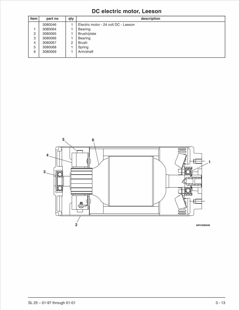
DC electric motor, Leesonitem part no qty description
3080046 1 Electric motor - 24 volt DC - Leeson1 3080064 1 Bearing2 3080065 1 Brush/plate3 3080066 1 Bearing4 3080067 2 Brush5 3080068 1 Spring6 3080069 1 Arm/shaft
SL 25 – 01-97 through 01-01 3 - 13
3
6
1
4
5
2 AWV3080046

DC electric motor, Ohioitem part no qty description
3080046 1 Electric motor - 24 volt DC - Ohio1 3080049 1 Brush/ring, complete2 3080050 4 Brush3 3080051 4 Brush spring4 5560585 2 Machine screw #10-24 x 1/2 inch long pan head5 5560586 4 Washer 3/8 star tooth lock6 5560587 4 Nut 3/8-16 heavy hex jam7 970509 2 Capscrew 3/8-16 x 2 inch long hex head grade 58 3080052 4 Insulator washer9 3080053 2 Insulator
10 3080054 1 Bearing11 3080055 1 Bearing12 3080056 1 Bearing spring washer13 3080057 1 Pulley end cover14 5560588 2 Thru bolt15 3080058 1 Retaining ring16 3080059 1 Brush inspection cover17 3080060 1 Brush inspection cover18 5560589 1 Machine screw #10-32 x 3/4 inch long pan head19 5560590 1 Nut #10-24 square20 3080061 1 Fan
3 - 14 SL 25 – 01-97 through 01-01
13
11
1520142
34
1
10
12
See detail - A
1918
17
16
65
8
8
5 7
9
Detail - A
AWV00328

Platform control cableitem part no qty description
302934 1 Platform control cable1 1 Cable - (not sold separately)2 3049818 1 Shrink warp x 3 inch long3 3049813 1 Connector 12 pin4 3049814 1 Lock wedge 12 pin plug5 3040342 26 Socket contact6 3049861 1 Connector, 14 pin plug
SL 25 – 01-97 through 01-01 3 - 15
34
5
2
1
56 AW302934

Proximity switchitem part no qty description
302802 1 Proximity switch1 3049804 1 Connector 2 pin2 3049808 1 Lock wedge 2 pin plug3 3040341 2 Pin, contact
3 - 16 SL 25 – 01-97 through 01-01
1 2 3 AW302802

Wire harness, mainitem part no qty description
302787 1 Wire harness, main1 3040342 31 Socket contact2 3049803 2 Connector 2 pin3 3049807 2 Lock wedge 2 pin plug4 3049813 2 Connector 12 pin5 3049814 2 Lock wedge 12 pin plug6 3049820 1 Contact plug, 3 contact7 3049822 1 Contact plug wedge, 3 contact
SL 25 – 01-97 through 01-01 3 - 17
1 14 45 5
123
12
3
16
7
AW302787


Section 4. - Factory installed options
SL 25 – 01-97 through 01-01 4 - 1

AC generatoritem part no qty description
1 301744 1 Cable, red2 302758 1 Cable, black3 302629 1 Feed thru stud, battery4 3040268 3 Insulator boot5 455536 1 Motor generator6 970269 4 Capscrew 5/16-18 x 1-1/4 inch long hex head grade 57 5560031 4 Nut 5/16-18 self locking8 986269 9 Washer 5/16 medium flat9 5560350 4 Carriage bolt 3/8-16 x 1 inch long
10 5560033 4 Nut 3/8-16 self locking11 5093004 3 Clamp12 584926 1 Cable, black
4 - 2 SL 25 – 01-97 through 01-01
12
14
3
56
78
41
4 26
78
11
7 9 10 11
AWM00334

Air line to platformitem part no qty description
1 019047 1 Coupler, quick disconnect2 019067 1 Dust cap, coupler3 984529 2 Nut sert 1/4-204 599624 1 Bracket, air line mounting5 970029 2 Capscrew 1/4-20 x 3/4 inch long hex head grade 56 987099 2 Washer 1/4 medium lock7 590144 1 Coupling, air line8 019057 1 Coupler, quick disconnect nipple9 563436 2 Fitting, 1/2 inch hose to 3/8 NPT
10 475346 2 Clamp11 599984 1 Hose 1/2 inch low pressure x 441 inch long12 5093008 14 Clamp
SL 25 – 01-97 through 01-01 4 - 3
AW786023
4
12
35
6
7
8
9 10
11
10
911Platform
Base Frame

Battery condition indicatoritem part no qty description
1 487696 1 Gauge, battery condition indicator2 7110031 1 O-ring3 300802 1 Jumper wire4 0181103 1 Jumper wire
4 - 4 SL 25 – 01-97 through 01-01
Upper control box
12
3
4
AW302850-1
5

Dual lanyard attachmentitem part no qty description
1 0360892 2 Tie down D ring2 0360891 2 Bracket, lanyard attachment3 0360893 1 Plate, lanyard attachment4 5560704 4 Capscrew 3/8-16 x 1-1/4 inch long hex head grade 85 986299 4 Washer 3/8 medium flat6 5560033 4 Nut 3/8-16 self locking7 0150448 2 Decal, attach fall restraint
SL 25 – 01-97 through 01-01 4 - 5
A A
B
B7
7
SECTION B-B
1 3
4 5 6
SECTION A-A
1 2
45
6
AWA36030B-3

Dual flashing lightsitem part no qty description
1 301494 2 Angle, light mount2 564136 2 Flashing light, yellow3 3040082 2 Terminal .250 tab male slip-on fully insulated 16/14 wire4 3040083 2 Terminal .250 tab female slip-on fully insulated 16/14 wire5 487686 2 Guard, flashing light6 5093018 2 Clamp7 5560004 8 Nut 1/4-20 self locking8 970049 8 Capscrew 1/4-20 x 1 inch long hex head grade 59 5569927 16 Washer 1/4 wide flat
10 974689 4 Machine screw #10-24 x 3/4 inch long round head11 5560034 4 Nut #10-24 self locking12 986009 8 Washer #10 medium flat13 3040046 2 Terminal .250 tab male slip-on fully insulated 22/18 wire14 3040047 2 Terminal .250 tab female slip-on fully insulated 22/18 wire15 302849 1 Wire harness, motion lights16 3049809 1 Strain relief17 3011802 1 Wire 18 gauge, 2 conductor x 79 inch long18 3011802 1 Wire 18 gauge, 2 conductor x 8 inch long19 3011802 1 Wire 18 gauge, 2 conductor x 45 inch long20 3044070 2 Terminal butt connector insulated 22/18 wire21 3040476 2 Shrink tube x 2 inch long22 3049803 1 Connector 2 pin23 3040342 2 Socket contact24 3049807 1 Lock wedge 2 pin plug
4 - 6 SL 25 – 01-97 through 01-01

Dual flashing lights
SL 25 – 01-97 through 01-01 4 - 7
BLK
RED
BLK
WHT
LEFT-HAND SIDE
RIGHT-HAND SIDE
BLK
RED
BLKWHT
5WHTBLK
PIN
2
PIN
1W
HITE
BLA
CK
BLK
WHT
BLK
WH
T
BLK
WH
T
1516 22
2324
17
2 3 14
134
19
2021
14 32
13 4
18
A
A
SECTION A-A
2
9 8 7
987
5
6
1112
1
10
AWA36033A

Flashing lightitem part no qty description
1 301494 1 Angle, light mount2 302847 1 Wire harness, flashing light3 3040082 1 Terminal .250 tab male slip-on fully insulated 16/14 wire4 3040083 1 Terminal .250 tab female slip-on fully insulated 16/14 wire5 487686 1 Guard, flashing light6 5093019 2 Clamp7 564136 1 Flashing light, yellow
300159 1 Flashing light, blue8 5560004 4 Nut 1/4-20 self locking9 970049 4 Capscrew 1/4-20 x 1 inch long hex head grade 5
10 986019 8 Washer 1/4 wide flat11 974689 2 Machine screw #10-24 x 3/4 inch long round head12 5560034 2 Nut #10-24 self locking13 986009 4 Washer #10 medium flat14 3040046 1 Terminal .250 tab male slip-on fully insulated 22/18 wire15 3040047 1 Terminal .250 tab female slip-on fully insulated 22/18 wire16 302849 1 Wire harness, motion lights17 3049809 1 Strain relief
4 - 8 SL 25 – 01-97 through 01-01
WHT
BLK
RED
BLK
BLK WHT
5
14 4
15 3
2
7
17
16
2
10987
5
6
89
10
AW302848

Key switchitem part no qty description
1 486756 1 Switch, key type488216 1 Replacement key
2 302874 1 Jumper wire3 302859 1 Jumper wire4 480006 1 O-ring
SL 25 – 01-97 through 01-01 4 - 9
Lower control box
14
Fuse
Key Switch
EmergencyStop
1 2
3
AW302873

Lift alarmitem part no qty description
1 3040593 1 Alarm2 3040038 1 Fuse holder, in-line3 3040039 1 Fuse, 10 amp capacity4 3011801 1 Wire red 18 gauge single conductor x 2 inch long5 3011801 1 Wire black 18 gauge single conductor x 22 inch long6 3044146 1 Terminal #10 ring tongue insulated 22/18 wire7 3044142 2 Terminal #10 ring tongue insulated 22/18 wire8 3049952 1 Terminal 1/4 ring tongue insulated 22/18 wire9 970029 1 Capscrew 1/4-20 x 3/4 inch long hex head grade 5
10 987099 1 Washer 1/4 medium lock
4 - 10 SL 25 – 01-97 through 01-01
REV
RIGHT
LIFT
DUMP
LEFT
FWD DRIVE
STEER
MAIN CONTROLVALVE (FRONT)
ME
DS
P
910 1
23
84
7
6
AWA36032A
5

Operator hornitem part no qty description
1 560332 1 Switch, push button2 3040341 1 Pin, contact3 960359 1 Terminal, #6 spade 18-14 wire4 964749 1 Wire, 16 gauge single conductor x 30 inch long5 0071269 1 Placard, horn
SL 25 – 01-97 through 01-01 4 - 11
12
2
1 5 23
4
34
Upper control box AW302850-2

Overload alarmitem part no qty description
1 3020115 1 Pressure switch, 625-3500 psi2 3040046 2 Terminal .250 tab male slip-on fully insulated 22/18 wire3 3040047 1 Terminal .250 tab female slip-on fully insulated 22/18 wire4 475496 1 Clamp5 560658 1 Pop rivet #AD36-ABS6 970029 2 Capscrew 1/4-20 x 3/4 inch long hex head grade 57 986019 2 Washer 1/4 medium flat8 5560004 1 Nut 1/4-20 self locking
4 - 12 SL 25 – 01-97 through 01-01
J2
3
2
1
67
8
4
5
JMP3
JMP4
AWA36007B
Lift cylinder
Lower control box
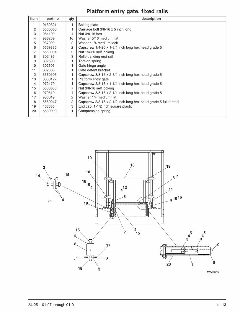
Platform entry gate, fixed railsitem part no qty description
1 0180821 1 Bolting plate2 5560353 1 Carriage bolt 3/8-16 x 5 inch long3 984109 4 Nut 3/8-16 hex4 986269 16 Washer 5/16 medium flat5 987099 2 Washer 1/4 medium lock6 5569886 2 Capscrew 1/4-20 x 1-3/4 inch long hex head grade 57 5560004 2 Nut 1/4-20 self locking8 302486 3 Roller, sliding end rail9 302590 1 Torsion spring
10 302603 1 Gate hinge angle11 302606 1 Gate detent bracket12 5560106 1 Capscrew 3/8-16 x 2-3/4 inch long hex head grade 513 0360127 1 Platform entry gate14 972479 1 Capscrew 3/8-16 x 1-1/4 inch long hex head grade 515 5560033 7 Nut 3/8-16 self locking16 970519 4 Capscrew 3/8-16 x 2-1/4 inch long hex head grade 517 986019 2 Washer 1/4 medium flat18 5560247 2 Capscrew 3/8-16 x 2-1/2 inch long hex head grade 5 full thread19 468886 3 End cap, 1-1/2 inch square plastic20 5530009 1 Compression spring
SL 25 – 01-97 through 01-01 4 - 13
2
81
334455
20
17
318
154
8
15
4
3
14
13 19
19
11
4 1516
10
4
16
412
4159
19
8
15
6 7
AWM00316

Platform entry gate, folding railsitem part no qty description
1 0180821 1 Bolting plate2 5560353 1 Carriage bolt 3/8-16 x 5 inch long3 984109 3 Nut 3/8-16 hex4 986269 9 Washer 5/16 medium flat5 987099 2 Washer 1/4 medium lock6 5569886 2 Capscrew 1/4-20 x 1-3/4 inch long hex head grade 57 5560004 4 Nut 1/4-20 self locking8 302486 3 Roller, sliding end rail9 302590 1 Torsion spring
10 302604 1 Gate hinge bracket11 302570 1 Gate detent bracket12 972569 2 Carriage bolt 1/4-20 x 3/4 inch long13 0360127 1 Platform entry gate14 970469 3 Capscrew 3/8-16 x 1 inch long hex head grade 515 5560033 5 Nut 3/8-16 self locking16 970519 1 Capscrew 3/8-16 x 2-1/4 inch long hex head grade 517 5560678 2 Washer 5/8 medium flat18 5560247 1 Capscrew 3/8-16 x 2-1/2 inch long hex head grade 5 full thread19 468886 3 End cap, 1-1/2 inch square plastic20 5530009 1 Compression spring
4 - 14 SL 25 – 01-97 through 01-01
2
8
345
345
120
4
17
318
15
8
13
1919
7 11 1210
41415
19
9
8416
6 7
AWM00317

Scissor guardingitem part no qty description
1 302684 1 Rear step2 302696 2 Guard mount angle3 302695 1 Guarding, scissor mesh4 5560004 8 Nut 1/4-20 self locking5 972579 8 Carriage bolt 1/4-20 x 1/2 inch long6 986019 14 Washer 1/4 medium flat7 553556 8 Clamp8 970029 6 Capscrew 1/4-20 x 3/4 inch long hex head grade 59 972489 2 Capscrew 3/8-16 x 1-1/2 inch long hex head grade 5
10 984109 2 Nut 3/8-16 hex11 5560033 5 Nut 3/8-16 self locking12 986269 5 Washer 5/16 medium flat13 972439 3 Carriage bolt 3/8-16 x 1-1/4 inch long
SL 25 – 01-97 through 01-01 4 - 15
75
464
68
View A – A
A
A2
1 3
1112
13910
1112 AWM00315

Spare battery trayitem part no qty description
1 302458 1 Removable tray2 302457 2 Battery hold down angle3 3040269 8 Insulator boot4 302547 2 Angle, plastic battery insulator5 584926 3 Battery wire6 5560350 4 Carriage bolt 3/8-16 x 1 inch long7 5560033 4 Nut 3/8-16 self locking8 986299 4 Washer 3/8 medium flat9 3050009 4 Battery, 6 volt DC - 220 amp hour
3050027 4 Battery, 6 volt DC - 240 amp hour
4 - 16 SL 25 – 01-97 through 01-01
1
95
678
24
3
AW302612

index
BBase frame, 1-3Battery charger, standard - Lester, 1-15, 3-11Battery charger, world - Lester, 1-15, 3-11Battery hold down angle, 1-15, 4-16Battery tray, 1-15Battery, 6 volt DC - 220 amp hour, 4-16Battery, 6 volt DC - 240 amp hour, 1-15, 4-16Bearing hub, 1-3, 1-7Bracket, air line mounting, 4-3Bracket, brake cylinder, 1-3Bracket, contactor, 3-5Bracket, emergency bleed down, 1-16, 1-20Bracket, power plate, 3-2, 3-5Brake pin, left hand, 1-3Brake pin, right hand, 1-3Bus bar, 3-2, 3-5
CCable, manual lowering, 1-16Cable, quick disconnect, 1-10, 1-15Cable, rollout detent, 1-22, 1-25Cartridge valve, manual pull, 1-16, 1-20Channel, tray latch, 1-9, 1-15Circuit breaker, 5 amp thermal, 3-2, 3-5Contact block, emergency stop switch, 3-6, 3-9Contactor, 24 volt DC, 3-5Control box, lower, 3-2, 3-5Control valve, main, 1-9, 2-2Controller, upper control box, 3-9, 3-12Corrosion inhibitor, 3-2, 3-5, 3-6, 3-9Cover, base frame rear, 1-30Cover, brake cylinder, 1-30Cover, electrical outlet, 3-10Cover, hydraulic oil reservoir, 1-9Cover, platform cable, 1-22, 1-25Cylinder, brake, 1-2, 2-6, 2-7, 2-8Cylinder, cushion, 1-9Cylinder, lift, 1-20, 2-9, 2-10Cylinder, steering, 1-4, 2-11, 2-12
DDecal set, valve, 2-2Decal, 125 volt 15 amp power to platform, 3-10Decal, attach fall restraint, 4-5Decal, battery charge, 1-30Decal, caution cylinder disassembly, 1-30Decal, caution no step, 1-30Decal, check battery before charging, 1-30Decal, danger cylinder failure, 1-30Decal, danger pinch point, 1-30Decal, danger safety prop, 1-30Decal, danger shearing/crushing, 1-30Decal, danger swing down rails, 1-30Decal, danger tipover hazard, 1-30Decal, danger tipover/electrical hazard, 1-30Decal, danger towing instructions, 1-30Decal, do not alter, 1-30Decal, emergency stop, 1-30Decal, fork lift here, 1-30Decal, hydraulic fluid level, 1-30Decal, hydraulic oil level, 1-30Decal, hydraulic schematic, 1-30Decal, lower controls, 1-30Decal, lube recommendations, 1-30Decal, made in USA, 1-30Decal, mounting plate, 1-25Decal, OmniQuip logo, 1-30
Decal, operating manual enclosed, 1-30Decal, pinch point, 1-30Decal, SL 25 logo, 1-30Decal, Snorkel brand logo, 1-30Decal, Snorkel logo, 1-30Decal, warning stripes, 1-30Detent pin, 1-22, 1-25Diagnostic nipple, 1-10, 2-2Dust cap, 1-7
EElectric motor - 24 volt DC, 1-9, 3-13, 3-14Electrical hazard
See inside front coverElectrical outlet, GFCI - 20 amp capacity, 3-10Electrical outlet, standard - 20 amp capacity, 3-10Emergency power switch, 3-6, 3-9
FFlashing light, blue, 4-8Flashing light, yellow, 4-6, 4-8Folding rail gate, 1-22, 1-25Fuse block, double, 3-2, 3-5Fuse holder, in-line, 4-10Fuse, 10 amp capacity, 4-10Fuse, 250 amp capacity, 3-2, 3-5
GGauge, battery condition indicator, 4-4Ground strap, 1-30Guard, emergency stop switch, 3-2, 3-5Guard, flashing light, 4-6, 4-8
HHour meter, 3-2, 3-5Hub, 1-3, 1-7Hydraulic drive motor, 1-2, 2-13, 2-14Hydraulic gear pump, 1-9Hydraulic oil reservoir, 1-9Hydraulic tray, 1-9
IInsulator boot, 1-10, 1-15, 4-2, 4-16
JJoystick controller, 3-6
LLevel sensor, 2 axis - 2° and 4°, 1-3Lift cylinder cartridge valve, 1-16, 2-15Link half, stabilizer foot, 1-3Lower control box, 1-9, 3-2, 3-5
MMachine bushing, 1-20Manifold valve, 2-2, 2-4Manual bleed down cartridge valve, 2-4
PPin cap, steering, 1-3Pin, lower arm slider, 1-16Placard, ANSI standard, 1-30Placard, caution serial number, 1-30Placard, emergency bleed down valve, 1-30Placard, horn, 4-11Placard, lower control box, 1-30, 3-2, 3-5
SL 25 – 01-97 through 01-01 index 1

Placard, upper control box, 1-30, 3-6, 3-9Platform, 1-22Platform control cable, 1-9, 3-15Platform entry gate, 4-13, 4-14Pothole protection linkage, 1-3Printed circuit board, lower control box, 3-2, 3-5Proximity switch, 1-2, 1-16, 3-16Pump mounting plate, 1-9
RRecord box, 1-30Relief/check valve, 1-9, 2-16Retaining ring, 1-20Roller, lower arm set, 1-16Roller, sliding end rail, 1-16, 1-22, 1-25, 4-13, 4-14Rollout extension deck, 1-22Rollout extension deck, folding rails, 1-25Rollout railing, fixed, 1-22
SSafety prop, 1-16Scissor arm stack, 1-16, 1-20Slide pad, 1-22, 1-26Slider block, lower arms, 1-16Snap pin with lanyard, 1-25Stabilizer foot, 1-3Stabilizer skid, 1-3Steering spindle, left hand, 1-3Steering spindle, right hand, 1-3Suction strainer, 1-10Suction tube, 1-9Switch, battery disconnect, 3-2, 3-5Switch, key type, 4-9Switch, push button, 4-11Switch, toggle, 3-2, 3-5, 3-6, 3-9
TTire, solid non-marking 5 x 8 white, 1-4Tray latch torsion spring, 1-9, 1-15
UUpper control box, 3-9
VValve cartridge, adjustable flow control, 1-16
WWarranty
See inside back coverWire harness, flashing light, 4-8Wire harness, lower control box internal, 3-2, 3-5Wire harness, main, 1-9, 3-17Wire harness, motion lights, 4-6, 4-8Wire harness, upper control box internal, 3-6, 3-9
index 2 SL 25 – 01-97 through 01-01
Index

LIMITED WARRANTYSnorkel warrants each new machine manufactured and sold by it to be free from defects in material and workmanship for aperiod of one (1) year from date of delivery to a Customer or for one year after the machine has been placed in first service in aDealer rental fleet, whichever comes first. Any part or parts which, upon examination by the Snorkel Service Department, arefound to be defective, will be replaced or repaired, at the sole discretion of Snorkel, through its local Authorized Dealer at nocharge.
Snorkel further warrants the structural components; specifically, the mainframe chassis, turntable, booms and scissor arms,of each new machine manufactured by it to be free from defects in material and workmanship for an additional period of four(4) years. Any such part or parts which, upon examination by the Snorkel Service Department, are found to be defective willbe replaced or repaired by Snorkel through its local Authorized Dealer at no charge; however, any labor charges incurred asa result of such replacement or repair will be the responsibility of the Customer or Dealer.
The Snorkel Service Department must be notified within forty-eight (48) hours of any possible warranty situation during theapplicable warranty period. Personnel performing warranty repair or replacement must obtain specific approval by SnorkelService Department prior to performing any warranty repair or replacement.
Customer and Dealer shall not be entitled to the benefits of this warranty and Snorkel shall have no obligations hereunderunless the “Pre-Delivery and Inspection Report” has been properly completed and returned to the Snorkel ServiceDepartment within ten (10) days after delivery of the Snorkel product to Customer or Dealer’s rental fleet. Snorkel must benotified, in writing, within ten (10) days, of any machine sold to a Customer from a Dealer’s rental fleet during the warrantyperiod.
At the direction of the Snorkel Service Department, any component part(s) of Snorkel products to be replaced or repairedunder this warranty program must be returned freight prepaid to the Snorkel Service Department for inspection. All warrantyreplacement parts will be shipped freight prepaid (standard ground) from the Snorkel Service Department or from Snorkel’sVendor to Dealer or Customer.
REPLACEMENT PARTS WARRANTY
Any replacement or service part made or sold by Snorkel is not subject to the preceding Limited Warranty beyond thenormal warranty period of the machine upon which the part was installed.
THIS WARRANTY EXCLUDES AND SNORKEL DOES NOT WARRANT:
1. Engines, motors, tires and batteries which are manufactured by suppliers to Snorkel, who furnish their own warranty.Snorkel will, however, to the extent permitted, pass through any such warranty protection to the Customer or Dealer.
2. Any Snorkel product which has been modified or altered outside Snorkel’s factory without Snorkel’s written approval, ifsuch modification or alteration, in the sole judgment of Snorkel’s Engineering and/or Service Departments, adverselyaffects the stability, reliability or service life of the Snorkel product or any component thereof.
3. Any Snorkel product which has been subject to misuse, improper maintenance or accident. “Misuse” includes but is notlimited to operation beyond the factory-rated load capacity and speeds. “Improper maintenance” includes but is notlimited to failure to follow the recommendations contained in the Snorkel Operation, Maintenance, Repair PartsManuals. Snorkel is not responsible for normal maintenance, service adjustments and replacements, including but notlimited to hydraulic fluid, filters and lubrication.
4. Normal wear of any Snorkel component part(s). Normal wear of component parts may vary with the type application ortype of environment in which the machine may be used; such as, but not limited to sandblasting applications.
5. Any Snorkel product that has come in direct contact with any chemical or abrasive material.
6. Incidental or consequential expenses, losses, or damages related to any part or equipment failure, including but notlimited to freight cost to transport the machine to a repair facility, downtime of the machine, lost time for workers, lostorders, lost rental revenue, lost profits or increased cost.
This warranty is expressly in lieu of all other warranties, representations or liabilities of Snorkel, either expressed or implied,unless otherwise amended in writing by Snorkel’s President, Vice President-Engineering, Vice President-Sales or VicePresident-Marketing.
SNORKEL MAKES NO WARRANTIES WHICH EXTEND BEYOND THE DESCRIPTION OF THIS LIMITED WARRANTY.SNORKEL MAKES NO IMPLIED WARRANTY OF MERCHANTABILITY OR FITNESS FOR A PARTICULAR PURPOSEAND DISCLAIMS ALL LIABILITY FOR INCIDENTAL OR CONSEQUENTIAL DAMAGES, INCLUDING BUT NOTLIMITED TO INJURY TO PERSONS OR PROPERTY.
The Customer shall make all warranty claims through its local Authorized Dealer and should contact the Dealer from whomthe Snorkel product was purchased for warranty service. Or, if unable to contact the Dealer, contact the Snorkel ServiceDepartment for further assistance.
Effective July 1995


SL 25 – revised December 2001 1
Maintenance and schematics
Maintenance informationThe parts drawings located in the repair parts sections,are designed for use as a guide for proper disassemblyof the machine and components as well as for parts re-placement.Always refer to the hydraulic system installa-tion drawings and the electrical wiring diagram beforeremoving or disassembling associated parts.
Do not attempt to disconnect or remove any hydrau-lic line before reading and understanding all textconcerning the system hydraulics. In most cases,disassembly of the machine will be obvious from theillustration.
When disassembling or reassembling components,complete the procedural steps in sequence. Do not par-tially disassemble or assemble one part, then start onanother. Always check your work to assure that nothinghas been overlooked.
The following list is a gentle reminder when disassem-bling or assembling the machine.
ü Always be conscious of weight.
ü Never attempt to lift heavy objects without the aid ofa mechanical device.
ü Do not allow heavy objects to rest in an unstablecondition.
ü Always make sure work platform is in stowedposition - blocked or the weight removed by asuitable lifting device before disconnecting thehydraulic hose from the motor/pump unit to the liftcylinder.
üWhen raising a portion of the machine, be sure thatadequate blocking is properly positioned - Do notdepend on lifting device to hold and secure weight.
ü If a part resists removal, check to see if allfasteners, electrical wiring, hydraulic lines, etc.,have been removed or that other parts are notinterfering.
Parts should be thoroughly inspected before restoring toservice at the time of reassembly. Burrs, nicks orscratches may be removed from machined surfaces byhoning or polishing with #600 crocus cloth, followed by athorough cleaning in an approved cleaning solvent, andblown dry with compressed air. Do not alter the contourof any part. If this operation does not restore the part to aserviceable condition, replace the part. Replace allO-rings, seals, and gaskets at reassembly. Use new rollpins or cotter pins. Dip all packing rings and seals in hy-draulic oil before reassembling in cylinder and manifoldinstallations.Replace any part having imperfect threads.In general, units that have been disassembled can bereassembled by reversing the order of disassembly.
Remember that the service life of a machine can be in-creased by keeping dirt and foreign materials out of thevital components. Precautions have been taken to safe-guard against this; shields, covers, seals and filters areprovided to keep air and oil supplies clean; however,these items must be maintained on a scheduled basis inorder to function properly.
At any time air or oil lines are disconnected, clean sur-rounding areas as well as the opening and fittings them-selves. As soon as a line or component is disconnected,cap or cover all openings to prevent the entry of dirt orforeign materials.
New parts should remain in their container until they areready to be used.
Clearly mark or tag hydraulic lines and electrical wiringconnections when disconnecting or removing them fromunit. This will assure that they are correctly reinstalled.
Proper assembly is critical to the successful rebuildingof any unit. Carefully inspect any parts which are to bereused. If in doubt, replace.
“SAFETY FIRST” is a good slogan.
Replace any guards and protective devices that havebeen removed to carry out maintenance and repairwork.
CAUTION

2 SL 25 – revised December 2001
Maintenance schedules
Snorkel has established a Preventive MaintenanceSchedule that includes Daily Maintenance (Operator'sInspection), 90 Day or 150 Hour (frequent) Maintenanceand Yearly or 500 Hour (annual) Maintenance, to detectany defective, damaged or improperly secured partsand provide information regarding lubrication and otherminor maintenance items.
The Maintenance Schedule following, outlines the re-quirements of these maintenance checks for each timeinterval. The Operator's Daily Maintenance and inspec-tion must be performed by a trained operator. All othermaintenance and inspections must be performed by atrained service technician only.
Note that the 90 Day or 150 hour (frequent) and yearly or500 hour (annual) Maintenance, require use of the Pre-ventive Inspection Maintenance Checklist to pinpoint allinspection items. Retain a copy of these forms for yourrecords.
They also require that all placards and decals on the unitare to be inspected.
All placards and decals must be in place and legible.Usethe placards installation drawing and parts listing in therepair parts section 1 of this manual to check these plac-ards and decals.
Snorkel recommends that you make additional copies ofthe Preventive Inspection Maintenance Checklist formsfor your use in performing these inspections.
Failure to perform the Preventive Maintenance atthe intervals outlined in the Maintenance Schedulemay result in a unit being operated with a defect thatcould result in INJURY or DEATH of the unit opera-tor. Do not allow a unit to be operated that has beenfound to be defective.
Repair all defects before returning the unit to service.
Daily maintenance - (operator’s inspection)
Components Service Required
Operator’s manual In document holder
Battery fluid level Proper level
Battery Terminals Clean, connections tight
Battery Charger Proper operation
Cables and wiring harness No wear or physical damage
Hydraulic fluid level Check fluid level
Hoses, tubes, and fittings No leaks
Free-wheeling valve Fully closed
Tires and wheels Good condition
Parking brakes Proper cam orientation
Ground strap In place and securely fastened
Operating controls Proper operation
Emergency stop Shuts off controls
Lowering alarm Proper operation
Pothole protector interlock Proper operation
Level sensor interlock Proper operation
Emergency lowering Proper operation
Safety prop No damage or deformation
Flashing light Proper operation
Weldments No damage or deformation
Rollers and slide blocks Proper operation, no damage
Fasteners In place and tight
Guardrail system No damage or deformation
Platform extension Proper operation
Operating controls Proper operation
Emergency stop Shuts off upper controls
DANGER

SL 25 – revised December 2001 3
Maintenance schedules
Daily maintenance - (operator's inspection) continued
Components Service Required
Lowering alarm Sounds when platform lowers
Drive motion alarm Sounds when platform moves
Battery condition indicator Proper operation
Lanyard anchors No damage or deformation
Horn Sounds when activated
Electrical power outlet Proper operation
Placards and decals In place and readable
90 day or 150 hour maintenance - (trained service technician)
Components Service Required Recommended Lubricant orFurther Instructions
Daily maintenance Perform maintenance as per schedule
Preventive inspection mainte-nance checklist
Perform inspection, complete form Retain copy of checklist
Placards and decals inspection Inspect using drawing and parts listingin section 1 (repair parts)
Replace any missing or unread-able decals/placards
Door hinges and latches Lubricate SAE 10W oil or spray lubricant
Batteries Check specific gravity 1.260/1.275 at 80° F.
Platform lift capacity Check if platform can lift maximum load
Platform lift/lower speeds Check smooth operation and speeds
Safety prop Check operation
Hydraulic return filter Check condition Replace if dirty
Pothole protection interlock Check operation per test on page 6 Remove from service and repair ifmachine does not pass testLevel sensor interlock Check operation per test on page 6
Charging system Check operation
Platform controller Check smooth operation and speeds
Scissor arm bearings Check condition Do not lubricate
Snap rings, steering yoke Check operation and tightness Replace if damaged
Yearly or 500 hour maintenance - (trained service technician
Components Service Required Recommended Lubricant orFurther Instructions
90 day or 150 hour maintenance Perform maintenance per schedule
Hydraulic oil reservoir Clean and replace fluid Above 10° Mobil DTE-13MBelow 10° Mobil DTE-11M
Hydraulic return filter Replace After 1st. 50 hours, thereafterat recommended interval
Hydraulic pressures Check pressures
Platform controller Check operation
Base controls Check operation
Wheel bearings Clean and repack Conoco Super Sta #2Above 32° Mobilgrease CM-PBelow 32° Mobilgrease CM-L

4 SL 25 – revised December 2001
Service information
Lubricants
Specific lubricants as recommended by Snorkel, shouldbe used in maintaining your unit. If in doubt regarding theuse of lubricants other than those listed, contact SnorkelCustomer Service Department, St. Joseph Missouri, forevaluation and recommendation.
Anytime the work platform is elevated to perform main-tenance work, properly position the safety prop as out-lined on the safety prop decal.
DO NOT reach through scissors mechanism unless thesafety prop is properly positioned. Injury or death couldoccur if the platform is not supported by the safety propand should suddenly drop onto personnel performingmaintenance work under the raised platform.
Refer to the above lubrication illustration for location ofitem numbers.
Pressure gun application
Service all fittings as indicated in the MaintenanceSchedule and lubrication illustration. Wipe away all ex-cess lubricant from exposed surfaces. Over lubricationcan collect dirt and foreign matter which acts as an abra-sive. Lubrication of accessory equipment should be inaccordance with the manufacturer’s recommendations.
King pins
King pins (item 1.): Pressure gun lubricate at recom-mended interval using lubricant as outlined in the main-tenance schedule.
Tie rods
Tie rods (item 2.): Pressure gun lubricate at recom-mended interval using lubricant as outlined in the main-tenance schedule.
Steer cylinder ends
Steer cylinder ends (item 3.): Pressure gun lubricate atrecommended interval using lubricant as outlined in themaintenance schedule.
Wheel bearings
Wheel bearings (item 4.): Clean and repack wheel bear-ings on non-drive wheels yearly, (or every 500 hours ofoperation), using specific lubricants and outlined in themaintenance schedule.
Clean and repack wheel bearings following normal au-tomotive procedures.
Note:The wheel bearings used on drive wheels are sealedbearings and do not require lubrication.
9
12
34
4 75610
8
The illustration locates the lubrication points of the SL 25.
Lubrication illustration
DANGER

Service information
Hydraulic oil reservoir
Hydraulic oil reservoir (item 5.): The fluid level should bekept level with the indicator line of the side of the reser-voir and should be checked with all cylinders fully re-tracted and the platform in stowed position.
The interior of the reservoir should be wiped out andcleaned each time the hydraulic oil is changed. The res-ervoir filler/breather cap should be removed and the capbreather cleaned yearly with Kerosene, Fuel Oil, orother solvent.
Any time the hydraulic oil is changed or added, it is abso-lutely necessary that only clean hydraulic oil is used.
Note:If it becomes necessary to add or use an oil otherthan the recommended fluid, it is important that it becompatible and equivalent to the factory fill. Local oilsuppliers can generally furnish this information.
If questions still remain, contact Snorkel Customer Ser-vice Department, St. Joseph, Missouri, for further infor-mation.
Return filter
Return filter (item 6.): The hydraulic oil return filter ismounted in the right hand tray close to the hydraulic oilreservoir.
The filter element is a throwaway type filter and shouldbe changed after the initial break-in period (approxi-mately 50 hours operation time).
The filter condition should be checked at the 90 day or150 hour Preventive Inspection Maintenance interval ormore frequently under extreme working conditions.
When changing the filter element, the oil inside of the fil-ter element, should be examined for deposits of metalcuttings, which if present, could indicate excessive wearin some of the system components.
Door hinges and latches
Door hinges and latches (item 7.): Lubricate at recom-mended interval using specific lubricants as outlined inthe maintenance schedule.
After lubricating, remove any excess oil or over spray soit will not collect dirt and debris.
Slide pads
Slide pads (item 8.): Check slide pads for excessivewear and replace as required. Slide pads do not requirelubrication.
Scissor arm bearings
Scissor arm bearings (item 9.): Scissor arm bearingsare self lubricating. Check bearings for signs of damageand excessive wear as outlined in the maintenanceschedule. Do not lubricate scissor arm bearings.
Batteries
Batteries (item 10.): The batteries and battery cablesshould be checked to assure that the connections aretight and free of corrosion. Fluid level should be main-tained to assure that the batteries will maintain propercharge.
Check the batteries specific gravity per the maintenanceschedule.
The batteries are enclosed within a tray located on theside of the machine. For access to the batteries whenthe machine is lowered, position the machine on a hardlevel surface, unlatch and open tray.
Lead-acid batteries contain sulfuric acid which will dam-age eyes or skin on contact. When working around bat-teries, ALWAYS wear a face shield to avoid acid in eyes.If acid contacts eyes, flush immediately with clear waterand get medical attention.
Wear rubber gloves and protective clothing to keep acid offskin, if acid contacts skin, wash off immediately with clearwater.
Lead-acid batteries produce flammable and explosivegases. NEVER allow smoking, flames or sparks aroundbatteries.
SL 25 – revised December 2001 5
DANGER

Service information
Pothole protection interlock test
Perform this test using the lower controls.
1. Stow the platform and position machine on asmooth, flat, level concrete slab.
2. Remove all persons and materials from the plat-form.
3. With the swing-out trays closed, check the groundclearance under the pothole protector skids (referto Figure 1). Clearance should be at least 3-3/4inch on both sides of the platform.
4. Raise the platform wile watching movement of theskids. The skids should lower to less than 1-1/4inch ground clearance when the platform is raisedapproximately 24 inches.
5. Fully lower the platform while watching movementof the skids. The skids should raise to their originalposition when the platform is lowered to approxi-mately 24 inches.
6. Place a 1-1/2 inch thick board, such as a 2 x 4, un-der the skid on the right side (refer to Figure 2).
7. The board will prevent the skid from lowering fully.Raise the platform while watching the skid. Whenthe skid contacts the board, the platform shouldstop raising and an alarm should sound at less thanseven (7) feet platform floor height. The alarmshould then sound when the platform switch is acti-vated. The platform should not raise any further.
8. Lower the platform, Place the board under the skidon the left side.
9. Raise the platform while watching the skid. Whenthe skid contacts the board, the platform shouldstop raising and an alarm should sound at less thanseven (7) feet platform height. The alarm shouldthen sound when the platform raise switch is acti-vated. The platform should not raise any further.
The potential for an accident increases when safetydevices do not function properly. Death or seriousinjury can result from such accidents. Do not alter,disable, or override any safety device.
10. If the platform raise function is not disabled, or thealarm does not sound, remove the platform fromservice until the problem is corrected.
Level sensor interlock test
Perform this test after verifying proper operation of thepothole protection interlock.
1. Position the platform on a smooth, flat, level sur-face.
2. Remove all persons and materials from the plat-form.
3. From the lower controls, raise the platform to ac-cess the level sensor at the front of the chassis (re-fer to Figure 3).
4. Pull the level sensor to the side as far as possiblewhile raising the platform.The platform should stopraising and the alarm should sound at approxi-mately seven (7) feet (2m) of platform elevation.
6 SL 25 – revised December 2001
Figure 1–Pothole protector skids
Figure 2–Pothole protector interlock test
DANGER
Level Sensor
Figure 3–Level sensor

Service information
5. If platform does not stop raising or the alarm doesnot sound, remove the machine from service untilthe problem is corrected.
The potential for an accident increases when safetydevices do not function properly. Death or seriousinjury can result from such accidents. Do not alter,disable, or override any safety device.
Battery care and maintenance
The following information about battery care and main-tenance was supplied by Interstate Batteries and is re-printed here with their permission.
1. New batteries need to be cycled several times be-fore reaching full capacity (20-50 cycles, depend-ing on type). Usage should be limited during thisperiod.
2. Always recharge batteries fully, immediately afteruse. Batteries perform best when they are fullycharged. More capacity and longer life will resultfrom this practice.
3. The deeper the discharge, the fewer number of cy-cles a lead-acid battery will deliver. Deep dis-charges deteriorate the battery quicker than lightershallow cycles.
4. Battery cables should be intact, and connectorskept tight at all times. Systematic inspection is rec-ommended.
5. Vent caps should be kept in place and tight duringvehicle operation and battery charging.
6. Batteries should be kept clean -- free of dirt andcorrosion -- at all times. Always keep the top of bat-teries clean. A film on top of the battery can causethe current to migrate between the posts, acceler-ating self discharge.
7. Never let the electrolyte level of a lead-acid batteryfall below the plates. Lack of maintaining the elec-trolyte in a lead-acid battery causes damage to theexposed portion of the plate which reduces capac-ity.
8. Always check electrolyte level before charging. Donot add water to individual cells unless plates areexposed. Batteries should be watered after charg-ing unless the plates are exposed before charging.If exposed before charging, the plates should becovered by approximately 1/8” of water. Check wa-ter level after charging. Water should be kept 1/4”below the bottom of the fill tube in the cell cover.
9. Water used to replenish batteries should be dis-tilled or treated to not exceed 200 T.D.S. (total dis-solved solids... parts per million). Particular careshould be taken to avoid metallic solids (iron).
10. A full charged battery will give you the best and lon-gest service.Be sure the batteries are fully chargedbefore testing or using. A fully charged battery,without a drain or load, after the surface charge hasdissipated, is 6.35 volts for a 6 volt battery.
11. Batteries should not be discharged below 20% of ca-
pacity (approximately 1.8 volts per cell under normaloperating load; 1.98 volts open circuit; 1.145 specificgravity). Proper battery sizing will help avoid exces-sive discharge.
12. Battery chargers should be sized to fully charge bat-teries in an eight hour period. Chargers should bekept in proper operating condition.
13. Do not use a mismatched charger of any type; i.e.,a 12 volt charger on a 24 volt pack or a 24 voltcharger on a 12 volt pack. An undersized chargerwill never get the job done, no matter how long ittries. An oversized charger will cause excess gas-sing and heat that could possibly result in a batterymeltdown and/or explosion.
14. Never charge a lead-acid battery with a sealed (gelcell) battery charger. The lead-acid battery needshigher voltage to finish its charge. Without it thebattery will never come back to 100% and sulfationcan occur.
15. Always allow batteries to cool off after charging.The cooling time is very important because heat isgenerated during the recharge and discharge cy-cles. Without the cooling time the heat grows, ac-celerating grid corrosion which is one of the majorcauses of battery failure. Charging practice shouldenable batteries to cool before use.
16. Deep cycle batteries need to be equalized periodi-cally.Equalizing is an extended, low current chargeperformed after the normal charge cycle. It helpskeep cells in balance. Actively used batteriesshould be equalized once per week. Manuallytimed chargers should have the charge time ex-tended approximately 3 hours. Automatically con-trolled chargers should be unplugged andreconnected after completing a charge cycle.
17. In situations where multiple batteries are con-nected in series, parallel, or series-parallel, a re-placement battery's should be of the same size,age, and usage level as the companion batteries.Do not put a new battery in a pack that has 50 ormore cycles. Either replace all the batteries withnew batteries or install a good used battery's inplace of the bad. New batteries should be given afull charge before use.
SL 25 – revised December 2001 7
6.30 volts = 93% charged6.27 volts = 89% charged6.25 volts = 85% charged6.22 volts = 80% charged6.10 volts = 50% charged5.94 volts = 20% charged
DANGER

Service information
18. Periodic battery testing is an important preventativemaintenance procedure. Hydrometer readings ofeach cell (fully charged) give and indication of balanceand true charge level.Imbalance could mean the needfor equalizing and is often a sign of improper chargingor a bad cell. Voltage checks (open circuit, chargedand discharged) can locate a bad cell or weak battery.Load testing will pick out a bad cell when other meth-ods fail. The point is to look for the abnormal. A weakcell or battery will cause premature failure of compan-ion cells or batteries respectively.
19. As batteries age, their maintenance requirementschange, Generally their specific gravity is higher andgassing voltage goes up. This means longer chargingtime and/or higher finish rate (higher amperage at theend of charge). Usually, older batteries need to be wa-tered more often and their capacity decreases.
20. “Opportunity charging”, a short partial charge during anextended duty cycle, is a controversial subject. Gen-erally, the practice is a “crutch” to make up for under-sized batteries. The correct approach is to installadequate battery capacity. If this is impossible becauseof lack of space in the battery compartment or extremeoperating conditions (24 hour intermittent use, as anexample), “opportunity charging” is better than exces-sive battery discharging. However, the practice cancause batteries to over heat, require more watering,and usually will shorten battery life. “Opportunity charg-ing” is a trade off; something to avoid if possible. Onecharging cycle per day is preferable.
21. Extreme temperatures can substantially affect bat-tery performance and charging. Cold reduces bat-tery capacity and retards charging. Heat increaseswater usage and can result in overcharging. Veryhigh temperature can cause “thermal run away”which may lead to and explosion or fire. If extremetemperature is an unavoidable part of an applica-tion, consult a battery/charger specialist aboutways to deal with the problem.
22. An overly discharged battery might need to be cy-cled a few times before it can recover fully. If a bat-tery begins to heat before coming up to a fullcharge, it might be necessary to discharge the bat-tery and recharge it a few times. The charge anddischarge cycle might help the current acceptanceof the battery and facilitate its recovery to a usablecondition.
23. Inactivity can be harmful to deep cycle batteries. Ifthey sit for several months, a “boost” charge shouldbe given -- more frequently in warm climate (aboutonce a month) than in cold (every 2-3 months).
24. Never store a battery in a discharged state.The sul-fate that forms during discharge can make the bat-tery impossible to recharge fully.
Battery charger
SL 25 units are equipped with an onboard automaticbattery charger. This charger has an electronic circuitthat will completely recharge the batteries and automati-cally turn off after the charge cycle is completed.
The charging cycle may last 1-1/2 to 16 hours depend-ing on the state of charge of the batteries. If the chargingcycle should exceed 16 hours without the batteries be-ing fully recharged, the charger should be shut off andthe batteries should be checked.
If the batteries show no signs of problems and the spe-cific gravity readings are within the range indicated pre-viously, then the charger should be checked.
General charging cautions1. Do not recharge batteries unless Electrolyte level
has been checked. Operate charger in accordancewith the battery charging instructions outline in thismanual. Place BATTERY DISCONNECT switch inthe “OFF” position before charging batteries.
2. Do not smoke or introduce a flame or spark in thecharging area.
Lead acid batteries generate highly explosive Hy-drogen gas, especially during charging cycle. Toavoid the possibility of an explosion, charge batter-ies only in a well ventilated area away form sparks orflame.
3. Use protective face and eye equipment whenchecking the condition of charging batteries.
8 SL 25 – revised December 2001
DANGER

SL 25 – revised December 2001 9
Preventive inspection maintenance
90 day or 150 hour checklist
OK OK - No Service Required Serial Number✔ Corrective Action RequiredX Corrected, (Record description of corrective action).
Inspection Procedures Codes(1) Weld cracks, dents and/or rust(2) Installation(3) Leaks(4) Operation(5) Condition(6) Tightness(7) Residue buildup(8) See placards and decals inspection chart
Check OK ✔ X
BaseframeStructural (1)Steering cylinder (2,3,4)Steering cylinder fasteners and linkage (1,2)Tires and wheels (5)Hydraulic tubes and hoses (3,5)Decals and placards (2,8)Cowling covers (5,6)Torque all wheel lug nuts/bolts per placard (2,6)Right drive motor (3,6)Left drive motor (3,6)Parking brakes (3,4)Free-wheeling valve (4,6)Cords and wire assemblies (2,5)Pothole protector interlock and alarm (1,2,4)Level sensor interlock and alarm (4,5)Swing-out trays (2,4,5)Lowering cushion valve (3,4)Hydraulic oil reservoir (3,5)Filler cap (6)Hydraulic fluid level (2,5)Return filter (2,6)Oil level tube (3,4)
Scissor arm stackStructural (1)Scissor arm pivot pins, snap rings and roll pins (2,5)Lift cylinder and valves (2,3,4)Safety prop (2,4,5)Manual lowering valve (4)Hydraulic tubes and hoses (3,5)Wires and electrical cables (2,5)Decals and placards (2,8)
Lower controlsControl select switch “BASE”platform controls do not work (4)Control select switch “PLATFORM”base controls do not work (4)Toggle switch, lift UP - DOWN (4)Lowering alarm (4)Battery disconnect switch “OFF”controls do not work (4)Emergency stop switch “OFF”controls do not work (4)Hour meter (4)
Check OK ✔ X
PlatformStructural (1)Guardrails properly installed and fastened (2,5)Platform entry chain or gate (2,5)Wires and electrical cables (2,5)Decals and placards (2,8)Correct operators manual in document holderRoll-out extension deck (2,4,5,8)Swing-down rails, detents and pins (2,4,5)
Upper controlsControl select switch (4)DRIVE/STEERcontrol select switch activated on “DRIVE” (4)Speed switch, speed 1 - SLOW (4)Speed switch, speed 2 - MEDIUM (4)Speed switch, speed 3 - FAST (4)Platform elevated, drives slow only (4)Platform lowered, drives fast, medium or slow (4)Platform UP/DOWN switch, UP - DOWNcontrol select switch activated on “PLATFORM” (4)Emergency stop “OFF”no controls work (4)
ElectricalMotor and hydraulic pump assembly (2,4)Batteries (2,4)Battery terminals (5,6,7)Battery electrolyte level (5)Battery specific gravity reading (5)Wires and cables (2,5,6)Battery charger (2,4,5)
Optional equipmentPlatform entry gate, spring loaded (2,4,5)Battery condition indicator (2,4)AC 110 volt outlet on platform (2,4)AC generator - battery operated (2,3,5)Operator horn (2,4)Motion warning alarm (2,4)Flashing light (2,4)Back-up horn (2,4)

10 SL 25 – revised December 2001
Preventive inspection maintenance
Corrective Action Required
Note: If correction action is required on any item, attach sheet indicating problem and action taken.
All items have been properly checked and tested and found to be operating satisfactory or necessary corrective action has been completed.
Inspected By: Date

Capscrew torque chart
SL 25 – revised December 2001 11
GRADE
BOLT
SAE GRADE
1 OR 2
SAE GRADE
5
SAE GRADE
6
SAE GRADE
8
MARKING
MIN. TENSILE
STRENGTH64,000 P.S.I. 105,000 P.S.I. 133,000 P.S.I. 150,000 P.S.I.
MATERIAL
DEFINITION
LOW
CARBON
STEEL
MEDIUM
CARBON
STEEL
TEMPERED
MEDIUM
CARBON
STEEL
Q & T
MED. CARBON
ALLOY
STEEL
Q & T
INDETERMINATE
QUALITY
MINIMUM
COMMERCIAL
QUALITY
MEDIUM
COMMERCIAL
QUALITY
BOLT SIZE
1/4
5/16
3/8
7/16
1/2
9/16
5/8
3/4
7/8
1
5
9
15
24
37
53
74
120
190
282
7
14
25
40
60
88
120
200
302
466
10
19
34
55
85
120
167
280
440
660
10.5
22
37
60
92
132
180
296
473
714
RECOMMENDED TORQUE VALUES (FT - LBS)
The following rules apply to the chart
1. Consult manufacturers' specific recommendations when available.
2. The chart may be used with both course and fine thread fasteners lightly lubricated.
3. Increase torque by 20% when multiple tapered tooth (shake proof) lock washers are used.
4. The torque values are given in foot-pounds.
5. Inch pound equivalent may be obtained by multiplying by 12.


Page 13
Hydraulic schematic
Snorkel model SL 25

Page 14
Wiring schematic
Snorkel model SL 25

Page 15
Wiring schematic
Snorkel model SL 25
