rehabilitation and maintenance of reinforced concrete bridge
TRANSCRIPT
1
Rehabilitation and Maintenance of Reinforced Concrete Bridge Decks using
Cathodic Protection System- A 30-year old Case Study
Meghdad Hoseini, Ph.D., P.Eng., Project Manager, WSP Canada Inc., Richmond, BC
Neil Cumming, P.Eng., Senior Consultant, WSP Canada Inc., Richmond, BC
John Fussell, P.Eng, Vice President, Transportation, Associated Engineering (BC) Ltd., Burnaby, BC
Shane Cook, P.Eng., Manager, Bridge Rehabilitation, Associated Engineering (BC) Ltd., Burnaby, BC
Paper prepared for presentation
at the EFFICIENT TRANSPORTATION -- MANAGING THE MAINTENANCE DEMAND Session
Of the 2016 Conference of the
Transportation Association of Canada
Toronto, ON

2
Abstract
The Arthur Laing Bridge connects the City of Vancouver with the Vancouver International Airport, and was opened in 1976. After only about six years in service the bridge began to develop symptoms of deterioration due to corrosion of the deck reinforcement. A major rehabilitation program was implemented in 1987, which included the installation of an impressed current cathodic protection (ICCP) system on about 45% of the 23,541 m2 deck. The cathodic protection (CP) system has effectively controlled the corrosion for almost 30 years and has resulted in a substantial reduction in the need for maintenance and rehabilitation during that time. In 2014 a comprehensive condition survey was completed and found the deck to be in relatively good condition. This paper will describe the design, implementation, operation, maintenance, and performance of the CP system after almost 30 years in service.
Introduction
Cathodic protection systems have been installed in many bridge decks since becoming commercially available in the early 1970s. The U.S. Federal Highway Administration (FHWA) has identified this method as “the only method that can stop the corrosion of reinforcement in concrete structures.”[1] Generally, cathodic protection systems are considered when a minimum extension to the service life of ten years is desired and no other alternative method is available or expected to effectively control established corrosion.
A U.S. Strategic Highway Research program (SHRP) report in 1992 [2] indicates that between 1973 and 1989 a total of 287 cathodic protection systems were applied to approximately 200 bridges throughout North America. Various types of systems and anodes have been developed by private and public agencies. However, mixed results regarding the performance of these systems have been reported in the literature. While some types of the cathodic protection systems and anodes have performed very well and a life extension of more than 20 years is expected for these systems, others have not performed as well as expected; in some instances the failures have occurred within five years of installation.
The poor performance of some of the systems has been primarily attributed to poor product durability, insufficient track record prior to system selection, improper installation, and/or poor technical specifications and system design.
The National Cooperative Highway Research Program (NCHRP) has conducted a survey [3] of state and provincial departments (ministries) of transportation (DOT or MOT) as well as the cathodic protection industry regarding compiling an inventory of the bridges with cathodic protection systems currently in service across the United States and Canada. The survey found that cathodic protection systems have been installed in 586 bridges in North America with 389 located in USA and 197 in Canada. Of this number, 279 of the systems have been installed on bridge decks. According to this report: “only three states in the USA - Florida, Missouri, and Oregon and three Canadian provinces - Alberta, New Brunswick, and Ontario, have adapted this technology and are actively implementing it. Other agencies have either not implemented the technology, implemented it on select projects with no commitment to extend it to larger scales, or have not had a satisfactory experience with this technology.”
Sohanghpurwala et al. [4] evaluated nineteen bridges in eleven states in the USA as well as Ontario in Canada to determine the effectiveness of various materials and configurations when used as cathodic protection systems. These structures were protected by various cathodic protection systems. A summary

3
of their findings is presented in Table 1. Overall, there are only a few examples of the systems with a documented operational life of more than fifteen years [1-7].
History of Arthur Laing Bridge
The Arthur Laing Bridge connects the City of Vancouver to Vancouver International Airport (YVR) in Richmond, BC and is operated and maintained by Vancouver International Airport Authority (YVRAA). It was constructed in 1975 and opened in 1976. The average traffic volume on the bridge was approximately 30,000 vehicles per day. The bridge consists of two essentially identical structures, each carrying two lanes of traffic in opposite directions. Each bridge is approximately 899 m in length and is composed of three compositely constructed centre spans totalling 229 m across the North Arm of Fraser River, with 671 m of elevated approaches constructed of cast-in-place, longitudinally post-tensioned concrete box girders. The centre spans are constructed of two variable depth steel box girders overlain by a 200 mm to 350 mm thick structural concrete slab which includes 2.6 m cantilever deck wings. The approximate area of the exposed concrete deck is 23,541 m2. Figures 1 and 2 show the general location and view of the bridge.
By the early 1980s, the deck was showing symptoms of damage (i.e. delamination and surface distress of the concrete deck surface) due to corrosion of reinforcing steel. The first available recording of the extent of delamination was 13 m2 in 1981, 150 m2 in 1983, and 383 m2 in 1984. A deck patching program was implemented in 1984 which encompassed 1.8% of the total deck area.
Between 1979 and 1985 five major condition assessment of the bridge were conducted. The results of these condition assessments indicated that corrosion had become quite advanced and a major rehabilitation program was recommended. In 1986 a more detailed condition survey was completed which showed the rate of deterioration between 1985 and 1986 was accelerating rapidly. The condition survey included: visual review, pachometer survey to determine the concrete cover thickness to reinforcing steel, delamination survey, half-cell potential survey, chloride concentration measurements, and core removal and evaluation. The surveys found that the causes of the delamination were corrosion of reinforcing steel due to insufficient concrete cover to the reinforcing steel (26% of the deck had less than 40 mm cover) and high chloride concentration at the depth of reinforcing steel due to high permeability of the original concrete. In addition, the bridge had a highly flexible deck with centre span deflections up to 50 mm under normal traffic loads. However, these deflections met the design criteria and the structural codes of the early 1970’s.
A major repair and rehabilitation program was planned in 1986 and was implemented in 1987. This rehabilitation included the installation of an impressed current cathodic protection (ICCP) system at select portions of the deck. Two of the authors had a significant involvement in the selection, design and implementation of this system. Acting on the advice of its engineering consultants, Transport Canada undertook the installation of the system and was responsible for operation and maintenance until 1991, after which the bridge became the responsibility of the Vancouver International Airport Authority (YVRAA). Since its inception Levelton/WSP has monitored and maintained this system on an annual basis on behalf of Transport Canada and YVRAA.
Rehabilitation Program
Based on the findings of 1986 condition survey, several rehabilitation alternatives with life-cycle analysis were developed [8]. The initial selected alternative was removal of delaminated concrete, partial removal of chloride-contaminated concrete (up to 25 mm depth), and application of a high density or latex-

4
modified concrete overlay. Cathodic protection was also considered, but was not recommended initially because of concerns that the concept for bridge deck applications was not sufficiently well-developed at that time.
Since high levels of chloride contamination were found in many areas of the reinforced concrete deck, it was determined that a vital component in a successful rehabilitation strategy would be removal of as much as possible of this contaminated concrete. However, since the concrete surrounding the top steel acts compositely with the steel in supporting the cantilever deck wings, its complete removal could result in a loss of structural support for the deck. Therefore, complete removal of all chloride contaminated concrete was not a feasible option. Recognizing that this would result in a very high potential for corrosion damage to continue due to ring-anode effect (i.e. corrosion of the reinforcement located at the perimeter of the repaired area in parent concrete), it was recommended that a cathodic protection (ICCP) system be considered. Following research into the details and effectiveness of CP systems for concrete structures, an impressed current CP system was chosen as the best option. Galvanic systems for bridge deck applications had not been developed for commercial use at that time.
Impressed current CP systems use a low voltage external electrical power source to distribute a direct current from an anode to the reinforcing steel. In such a system, if sufficient magnitude and direction of current is applied, the electrochemical potential of the rebar is shifted into the cathodic range and the anodic reaction that results in corrosion of the reinforcing steel will stop. The external current is usually applied by a rectifier. A schematic layout of an impressed current system is illustrated in Figure 3.
The advantage of this system is that the amount of the current can be adjusted at any time to optimize the protection provided to the existing steel within the area of influence of the rectifier and anode.
A thorough study was conducted to evaluate the state-of-the-art of the ICCP systems for the bridge decks. The study involved literature review, interviews with proprietors of various systems, interviews with the bridge owners with various systems in Canada and United States, and inspection of a number of completed installations. Several generic type of systems were considered [8]:
Conductive asphaltic overlays;
Slotted anode systems;
Conductive coating systems;
Top surface-mounted anode systems protected by a concrete overlay.
Of these systems, the latter was specified because it offered the most advantageous combination of practically, expected performance, and cost.
For the overlay, a latex-modified concrete overlay was deemed to be unsuitable due to potential incompatibility with the ICCP system as well as lack of experienced local contractors at that time. A high-density, low-slump concrete overlay was chosen to be used both with and without ICCP system.
The final rehabilitation scheme had the following features [8]:
Removal of chloride contaminated concrete by cold milling to the extent possible without compromising the structure or damaging the deck reinforcement (i.e. 15 to 25 mm depth);
Removal of delaminated concrete and patching in a checker-board pattern of 3 m squares to minimize the potential loss of structural support to the cantilever deck wings;

5
Installation of a wire-mesh anode cathodic protection system in areas of high corrosion activity or heavily chloride contaminated concrete;
Placement of a high-density, low-slump concrete overlay. The deck profile was adjusted where possible to provide a minimum of 50 mm cover to the anode mesh and rebar.
The installation of a median barrier was also included as part of the rehabilitation scheme.
In an attempt to reduce costs, a study was conducted to see if it was necessary to catholically protect the whole deck. It was found that there were many areas of acceptable cover thickness on the rebar, predominantly passive corrosion potentials, and little or no delamination. It was decided that these areas would not be cathodically protected. Ultimately 45% of the deck surface was protected in 15 zones, with areas ranging from 270 to 943 m2 with average zone area of 628 m2. Figure 4 shows the areas where the cathodic protection system was installed.
Design of Protection System
The primary features of the project specification related to the cathodic protection system were as follows:
Detailed design was conducted by the system supplier/manufacturer. Shop drawings to be approved by the Consultant;
Deliver 21.5 mA/m2 of protected steel;
Maximum anode to concrete current density: 110 mA/m2
Criteria for protection: cathodic protection polarization shift after 4 hours of 100 to 250 mV;
Minimize voltage drop through anodes by spacing current supply points at maximum 25 m intervals;
System divided into 15 independent zones supplied from three rectifier stations;
Provide two silver/silver chloride reference cells per zone, plus one additional for each 300 m2 in excess of 500 m2 per zone.
The system that was ultimately chosen employs a catalyzed titanium expanded anode mesh. This system had a major advantage over other available anode systems in that there are multiple redundant current paths which precluded the loss of a zone if the anode fractured. In addition, the mesh system could be cut and trimmed to fit around drains, joints, openings, and other obstructions. The mesh was supplied in 1.2 m wide rolls; the mesh was fastened to the deck with small plastic pins pushed into drilled holes. Flat current distributor bars were spot-welded to the mesh. The remainder of the wiring to the rectifiers was done in the conventional way, with connections to the current distributor bars passing up through holes cored in the deck. Three rectifier stations were used, controlling 5 zones each. Table 2 presents the details of the cathodic protection system in each of the 15 zones.
The primary features of the concrete overlay were as followings:
Compressive strength: 50 MPa at 28 days;
Minimum cement content: 400 kg/m3;
Maximum aggregate size: 12 mm;
Air content: Minimum 3%;
Spacing factor: 0.2 mm maximum;
Specific surface: 24 mm-1 minimum;
6
Maximum water/cement ratio: 0.35;
Coarse: fine aggregate: 65:35;
Maximum chloride content: 0.1% of mass of cement;
Curing: wet-burlap, minimum 7 days.
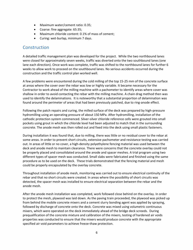
Construction
A detailed traffic management plan was developed for the project. While the two northbound lanes were closed for approximately seven weeks, traffic was diverted onto the two southbound lanes (one lane each direction). Once work was complete, traffic was shifted to the northbound lanes for further 6 weeks to allow work to proceed on the southbound lanes. No serious accidents occurred during the construction and the traffic control plan worked well.
A few problems were encountered during the cold milling of the top 15-25 mm of the concrete surface at areas where the cover over the rebar was low or highly variable. It became necessary for the Contractor to work ahead of the milling machine with a pachometer to identify areas where cover was shallow in order to avoid contacting the rebar with the milling machine. A chain drag method then was used to identify the delaminations. It is noteworthy that a substantial proportion of delamination was found around the perimeter of areas that had been previously patched, due to ring-anode effect.
Following the patch repairs and curing, the milled surface of the deck was prepared by high-pressure hydromilling using an operating pressure of about 150 MPa. After hydromilling, installation of the cathodic protection system commenced. Silver-silver chloride reference cells were grouted into small pockets using grout in which the chloride level had been adjusted to match that in the surrounding concrete. The anode mesh was then rolled out and fixed into the deck using small plastic fasteners.
During installation it was found that, due to milling, there was little or no residual cover to the rebar at some areas. In order to prevent short circuits, extensive pachometer and resistance testing was carried out. In areas of little or no cover, a high-density polyethylene fencing material was used between the deck and anode mesh to maintain clearance. There were concerns that the concrete overlay could not be properly placed and consolidated around the anode and spacer meshes. A trial program using two different types of spacer mesh was conducted. Small slabs were fabricated and finished using the same procedure as to be used on the deck. These trials demonstrated that the fencing material and mesh could be properly encapsulated by the overlay concrete.
Throughout installation of anode mesh, monitoring was carried out to ensure electrical continuity of the rebar and that no short circuits were created. In areas where the possibility of short circuits was detected, the spacer mesh was installed to ensure electrical separation between the rebar and the anode mesh.
After the anode mesh installation was completed, work followed close behind on the overlay. In order to protect the mesh, plywood was laid down. As the paving train proceeded, the plywood was picked up from behind the mobile concrete mixers and a cement slurry bonding agent was applied by spraying, followed by discharge of concrete onto the deck. Concrete was mixed using volumetric continuous mixers, which were operated on the deck immediately ahead of the bridge deck screeds. During prequalification of the concrete mixture and calibration of the mixers, testing of hardened air voids properties was conducted to ensure that the mixers would produce concrete with the appropriate specified air void parameters to achieve freeze-thaw protection.

7
Spreading, consolidation, and screeding was done using heavy twin vibrating bridge deck screeds working in tandem. The first screed was used for striking off and consolidating the concrete, while the second screed was used for final profiling and initial finishing. Work was coordinated to maintain continuous forward movement of the second screed with as few stops as possible. Final finishing was done using steel trowels to close surface irregularities, and a broom finish was applied.
Commissioning of the cathodic protection system began after the last concrete to be placed and had cured for 28 days. The total cost of the project (in 1987 Canadian Dollars) was approximately $2.45 million. This is equal to $114/m2 of the bridge deck and includes milling of the existing deck, delamination removal, substrate preparation, cathodic protection system, overlay placement, expansion joint replacement, and provison of a New Jersey type medial barrier [9].
Operation, Maintenance, Monitoring, and Performance of the System
Monitoring and maintenance of ICCP systems are somewhat complex. During the last 10-20 years, many transportation agencies (State DOTs, Ministries of Transportation, etc.) have found it difficult and costly to monitor and maintain ICCP systems. In the NCHRP survey [3], most respondents indicated that “the monitoring and maintenance are the main reasons for not selecting the cathodic protection systems.”
Maintenance and system adjustments must be conducted by qualified personnel. Many agencies do not have qualified in-house personnel for monitoring and maintenance.
Many respondents to NCHRP survey [3] believe that “the failure of their impressed current protection system is due to improper setting and insufficient current which indicates a lack of proper monitoring and maintenance.”
Arthur Laing Bridge has also not been exempt from maintenance issues. Following commissioning of the system, a number of issues were encountered.
In several of the 15 zones there were repeated failures of components of the rectifier circuitry. Some rectifies were replaced and surge protection devices were installed on the DC output. The supplier also recommended the reduction of the current settings that were originally specified. By these modifications, the system has operated satisfactorily.
In those zones where hardware failure did not occur, some difficulty in monitoring occurred because all of the permanent reference cells were located close to current distributor bars. As result, the depolarization shift between the distributor bars could only be evaluated using portable electrodes. Most of the depolarization shifts were found to exceed the maximum specified four-hour shift of 250 mV. Excessive depolarization shifts indicate overprotection, which can lead to evolution of gases at the anode and other difficulties. A reduced current setting resolved the issue.
During the majority of its 29 year operation, annual monitoring and adjustment of the system has been done by Consultant personnel with expertise in the installation and operation of ICCP systems. Monitoring and adjustment of the rectifiers has been conducted by the Owner’s staff on a regular basis (i.e .monthly) in accordance with the Consultant’s guidelines. The guidelines are updated every year and maintenance recommendations are provided to the Owner based on the findings of the Consultant’s annual review of the system. Table 3 presents an example of the annual recommended current output

8
levels as part of the maintenance program for 2014. The following provides a few examples of some of the additional maintenance recommendations [10]:
Repair/Replacement of the non-functioning analog meters or the selector dial of the rectifiers;
Cleaning/replacement of the dust screens inside the rectifiers to circulate the air and for cooling purposes;
Cleaning the exterior of the rectifiers to avoid accumulation of bird droppings;
Maintenance and cleaning of the locks in rectifiers;
Adjustment of the rectifiers’ output settings;
Adjustment in the system where the depolarization shifts did not meet or exceed the -100 mV depolarization criteria in some zones. Confirm of malfunctioning of a couple of reference electrodes
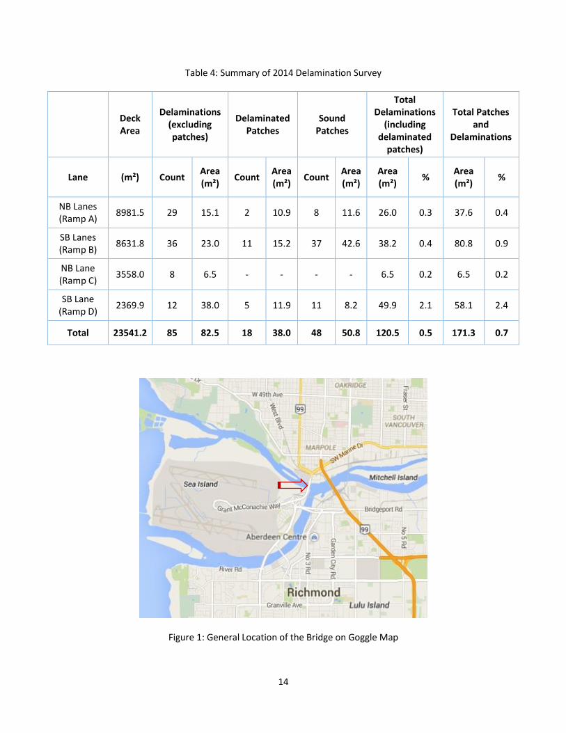
In the fall of 2014, a detailed condition survey of the bridge deck was conducted to evaluate the present condition of the deck [11]. The condition survey was the first detailed survey since commissioning of the cathodic protection system some 27 years previously. The assessment included a full visual condition survey of the top side of the deck, delamination survey (i.e. chain drag), half-cell potential survey, and laboratory analysis of water soluble chloride ion content of concrete. Note that it is not possible to conduct a meaningful half-cell potential survey in cathodically protected areas.
The condition survey found that visually, the exposed concrete deck is in fair to good condition with minor
amounts of delamination, patching, and cracking (mostly at non-cathodically protected areas). The results
of the delamination survey indicated that less than 1% of the deck is delaminated (see Table 4 for the
detail data). Figure 5 compares the delamination area of the deck measured during various condition
surveys during the service life of the bridge, to date. Moreover, approximately 93% of the deck area
surveyed is at a low probability for corrosion of the reinforcing steel. However, elevated corrosion
potentials are present in several areas of the deck with the majority (i.e. 5.2%) concentrated in an
unprotected area adjacent to a protected area (Figure 6). Further, the results of the laboratory analyses
indicated that the chloride ion concentrations at the level of the top mat of reinforcing steel at six of the
thirty sample locations are at or above the generally accepted corrosion initiation threshold of 0.03% to
0.05% by mass of concrete. Given the results of the field surveys it is clear that the ICCP system and the
thick concrete cover over the reinforcing steel have worked together to effectively protect the reinforcing
steel within the bridge deck. The performance of the deck in the 29 years since the 1987 rehabilitation
has been superior to the performance in the previous 12 years. The report also recommended that since
the chloride ion concentrations have reached or are approaching the initiation threshold at some
locations, it is important that the cathodic protection system is maintained in good working order.
Conclusions
One of the effective means of controlling corrosion of the steel reinforcement, extending the service life, and reducing the maintenance burden of the existing reinforced concrete bridge decks is the installation and operation of a cathodic protection system. If designed, installed, and operated correctly, this approach can result in sufficient corrosion protection to extend the service life of the structure, during which the need for ongoing maintenance and repairs will be relatively low. Most or all of the required maintenance could be carried out with minimal or no disruption to the travelling public. It is noteworthy,

9
however, that comprehensive monitoring and adjustment of the systems by experienced personnel are necessary to maintain proper protection levels and system operation.
Since the installation of the ICCP system in 1987, galvanic systems have been developed for bridge decks and have seen limited use. These carry a distinct advantage in that once installed, no further operation or maintenance is required. The anode configuration and spacing is selected to provide sufficient zinc to provide protection for the design life of the system. Once the zinc has been consumed no further protection will occur. The in-service experience of these galvanic systems is much shorter than that of the ICCP systems, and their long term effectiveness appears to be satisfactory but has not been proven. Nonetheless, these systems are considered by the authors to be worthy of consideration in appropriate circumstances.
Prior to deciding to implement a cathodic protection system, a detailed condition assessment of the concrete structure as well as a comprehensive study of existing systems and their potential effectiveness should be conducted.
NCHRP study [3] has concluded that ICCP systems using titanium mesh anodes and a new concrete overlay have a satisfactory documented in-service performance of up to thirty years to date. However, these systems require regular maintenance during their service life in the form of monitoring and adjustment of the current flow to the anode. Arthur Laing Bridge is a successful example of using this system in Canada. Today, the bridge carries more than 80,000 vehicles per day with minimum closures and traffic disruptions for the bridge deck concrete repair and maintenance.
References
[1] Scheffey, C. F., Bridge Deck Deterioration- A 1981 Perspective, FHWA Memorandum, 1981
[2] Broomfield, J. and J.S. Tinnea, Cathodic Protection of Reinforced Concrete Bridge Components, SHRP-C/UWP-92-618, Strategic Highway Research Program/ National Research Council, Washington, D.C., 1992
[3] Sohanghpurwala, A. A., Cathodic Protection for Life Extension of Existing Reinforced Concrete Bridge Elements, NCHRP Synthesis 398, Transportation Research Board (TRB), 2009
[4] Sohanghpurwala, A. A., and W. T. Scannell, Long-Term Effectiveness of Cathodic Protection Systems on Highway Structures, Report No. FHWA-RD-01-096, Federal Highway Administration, 2000.
[5] Teng, T.P., Long-term effectiveness of cathodic protection systems on highway structures, Publication No. FHWA-RD-01-096, FHWA, 2001,
[6] Lai D., The Evaluation of Bridge Deck Rehabilitation Strategies in Ontario, Annual Conference of the Transportation Association of Canada, 2008
[7] Sharp S., Brown M., Survey of Cathodic Protection Systems on Virginia Bridges, Report No. FHWA/VTRC 07-R35, Virginia Transportation Research Council, 2007
[8] Cumming N.A., Rogers T.F., Joseph A.P., Cathodic Protection of Arthur Laing Bridge, ACI SP-126: Durability of Concrete: Second International Conference, Montreal, Canada 1991

10
[9] Fussell J.B., Rehabilitation and Resurfacing of the Arthur Laing Bridge, Transport Asscociation of Canada (TAC) Annual Conference Proceedings, 1987
[10] Arthur Laing Cathodic Protection System Monitoring, WSP (Levelton Consultants), Various Reports Prepared for Vancouver International Airport Authority (YVRAA)
[11] Arthur Laing Bridge, Bridge Deck Evaluation Report, WSP (Levelton Consultants), December 2014

11
Table 1: Performance of Installed CP Systems [4]
Anode Material & Configuration
Environment No. of Systems
Age of Systems (years)
Protection Provided
Estimated Service Life (Years)
Impressed-current Cathodic Protection System
Arc-sprayed zinc Semi-marine & deicing
2 2 Poor (1) 10 to 15
Arc-sprayed zinc Marine 1 1 Excellent 7 to 21
Arc-sprayed zinc Deicing 1 8 Not determined
(2)
10 to 15
Titanium mesh Deicing 3 6 to 12 Excellent >25
Titanium mesh Marine 1 1 Excellent >25
Titanium ribbon Deicing 1 9 Excellent 15 to 25
Arc-sprayed titanium
Semi-marine & deicing
1 1 Poor (1) Not determined (3)
Arc-sprayed titanium
Marine 1 1 Poor (1) Failed in 1 year
Conductive paint Deicing 2 4 to 9 Good 5 to 10
Conductive polymer slotted
Deicing 1 12 Fair 5 to 10
Conductive polymer mounded
Deicing 1 15 Poor (1) 5 to 10
Coke breeze Deicing 3 5 to 9 Excellent 10 to 15
Galvanic Cathodic Protection Systems
Arc-sprayed zinc Marine 3 Excellent 7 to 10
Zinc foil with adhesive
Deicing 1 1 Excellent 7 to 10
Expanded zinc mesh and bulk
Marine 1 3 Good 15 to 20
(1) Systems operated at insufficient current output.
(2) No instrumentation installed to allow determination.
(3) System operated intermittently to allow proper evaluation.

12
Table 2: Details of the Cathodic Protection System in each of the 15 Zones
Rectifier # Zone # Area (m²) # Reference Cells
3 1 270.33 2
2 2 798.64 3
2 3 796.84 3
3 4 733.72 2
2 5 537.10 2
2 6 943.10 3
2 7 537.12 2
3 8 537.10 2
3 9 943.10 3
3 10 538.67 2
1 11 500.74 2
1 12 606.03 2
1 13 625.85 2
1 14 394.34 2
1 15 652.32 2

13
Table 3- 2014 Recommended DC Current Output Levels
Rectifier Number Unit Number Zone Number Current (Amperes)
1 1 11 1.15
1 2 12 2.40
1 3 13 2.10
1 4 14 1.55
1 5 15 2.00
2 1 2 5.00
2 2 3 3.40
2 3 5 4.20
2 4 6 7.65
2 5 7 4.10
3 1 1 4.90
3 2 4 5.55
3 3 8 0.00
3 4 9 6.35
3 5 10 4.05 Note 1- Current levels are to be maintained within 5% of the above noted current outputs until next year’s survey. Note 2- Increase or decrease the DC output as required by turning the dial associated with that zone.
14
Table 4: Summary of 2014 Delamination Survey
Deck Area
Delaminations (excluding patches)
Delaminated Patches
Sound Patches
Total Delaminations
(including delaminated
patches)
Total Patches and
Delaminations
Lane (m²) Count Area (m²)
Count Area (m²)
Count Area (m²)
Area (m²)
% Area (m²)
%
NB Lanes (Ramp A)
8981.5 29 15.1 2 10.9 8 11.6 26.0 0.3 37.6 0.4
SB Lanes (Ramp B)
8631.8 36 23.0 11 15.2 37 42.6 38.2 0.4 80.8 0.9
NB Lane (Ramp C)
3558.0 8 6.5 - - - - 6.5 0.2 6.5 0.2
SB Lane (Ramp D)
2369.9 12 38.0 5 11.9 11 8.2 49.9 2.1 58.1 2.4
Total 23541.2 85 82.5 18 38.0 48 50.8 120.5 0.5 171.3 0.7
Figure 1: General Location of the Bridge on Goggle Map

15
Figure 2: General view of the Bridge
Figure 3 - Schematic Layout of an Impressed Cathodic Protection System [3]

16
Figure 4 – Areas of Cathodic Protection System Installed on Arthur Laing Bridge [8]
Figure 5 – Comparison of Delamination Area during the Service Life of the Bridge to date [8, 9, 11]
13 m2
150 m2 1983 Survey
383 m2-Deck Patching Contract- Mid 1984
175 m2- Bridge Inspection Report Feb 1985
300 m2- Investigation April 1986
Investigation Feb 1987
Cathodic Protection
171 m2- 2014 Condition Assessment
0
200
400
600
800
1000
1200
1981 1983 1985 1987 1989 1991 1993 1995 1997 1999 2001 2003 2005 2007 2009 2011 2013 2015
Del
amin
atio
n (m
2)
Year

17
Figure 6 – High Half-cell Potential Measurements in an Area Adjacent to a Protected Area [11]