2002-005-c-04 user friendly guide for rehabilitation or ... friendly guide for rehabilitation or...
TRANSCRIPT
User Friendly Guide for Rehabilitation or Strengthening of Bridge Structures Using Fiber Reinforced Polymer Composites Report 2002-005-C-04 The research described in this report was carried out by Project Leader Dr. Sujeeva Setunge Team members Prof. Arun Kumar, Dr. Abe Nezamian and Dr Saman De Silva (RMIT)
Dr. Alan Carse, Mr. John Spathonis and Ms. Louise Chandler (QDMR) Mr. Dale Gilbert (QDPW) Mr. Bruce Johnson (Ove Arup) Prof. Alan Jeary (UWS) Dr. Lam Pham (CSIRO)
Research Program C: Delivery and Management of Built Assets Project 2002-005-C Decision Support Tools for Concrete Infrastructure rehabilitation

User Friendly Guide for Rehabilitation or Strengthening of Bridge Structures Using Fibre Reinforced Polymer Composites
ii
Content Summary
LIST OF TABLES ............................................................................................VI
LIST OF FIGURES..........................................................................................VII
EXECUTIVE SUMMARY .................................................................................IX
1 GENERAL..................................................................................................1
1.1 Introduction ................................................................................................... 1
1.2 Scope and Limitations .................................................................................. 2
1.3 Background Information............................................................................... 3
1.4 Structural Assessment ................................................................................. 4
1.5 Applications and Use.................................................................................... 4
1.6 Commercially Available Externally Bonded FRP Systems........................ 5 1.6.1 Wet lay-up systems.......................................................................................... 5 1.6.2 Prepreg systems .............................................................................................. 5 1.6.3 Precured systems ............................................................................................ 5
2 MATERIAL.................................................................................................6
2.1 Constituent Materials .................................................................................... 6 2.1.1 Resins ............................................................................................................... 6
2.1.1.1 Primer ........................................................................................................... 7 2.1.1.2 Putty fillers ................................................................................................... 7 2.1.1.3 Saturating resin............................................................................................ 7 2.1.1.4 Adhesives ..................................................................................................... 7 2.1.1.5 Protective coatings ...................................................................................... 7
2.1.2 Fibres ................................................................................................................ 7
2.2 Physical Properties ....................................................................................... 7 2.2.1 Density .............................................................................................................. 7 2.2.2 Coefficient of thermal expansion .................................................................... 8
2.3 Mechanical Properties .................................................................................. 8
2.4 Design Material Properties ......................................................................... 10
2.5 Commercially Available Externally Bonded FRP in Australia................. 11 2.5.1 MBrace composite strengthening systems (MBT Australia) ...................... 11
2.5.1.1 MBrace FRP fabric (sheet) materials ........................................................ 11 2.5.1.2 MBrace S&P CFK laminate strip (plate).................................................... 12

User Friendly Guide for Rehabilitation or Strengthening of Bridge Structures Using Fibre Reinforced Polymer Composites
iii
2.5.2 Sika® CarboDur structural strengthening systems.................................... 12 2.5.3 MBrace FRP strengthening systems ............................................................ 13
2.6 Time-dependent behaviour and durability ................................................ 13 2.6.1 Creep-rupture ................................................................................................. 13 2.6.2 Fatigue ............................................................................................................ 14 2.6.3 Durability......................................................................................................... 14
3 RECOMMENDED CONSTRUCTION REQUIREMENTS........................15
3.1 Shipping and Storage ................................................................................. 15 3.1.1 Shipping.......................................................................................................... 15 3.1.2 Storage............................................................................................................ 15
3.2 Techniques for FRP Strengthening ........................................................... 15 3.2.1 Basic technique.............................................................................................. 15
3.2.1.1 Substrate .................................................................................................... 16 3.2.1.2 Adhesive/Resin .......................................................................................... 16 3.2.1.3 FRP reinforcement ..................................................................................... 16
3.3 Temperature, Humidity, and Moisture Considerations............................ 17 3.3.1 MBrace FRP strengthening system .............................................................. 17
3.4 Equipment.................................................................................................... 18
3.5 Substrate Repair and Surface Preparation ............................................... 18 3.5.1 MBrace FRP strengthening systems (MBT Australia) ................................. 19
3.6 Reinforcement Details ................................................................................ 19 3.6.1 FRP debonding............................................................................................... 20 3.6.2 Concrete cover delamination ........................................................................ 20
3.7 Detailing of laps and splices ...................................................................... 21
3.8 Summary of Strengthening Techniques ................................................... 22
4 GENERAL DESIGN CONSIDERATIONS...............................................23
4.1 Design Philosophy ...................................................................................... 23 4.1.1 Verification of the serviceability limit state .................................................. 24 4.1.2 Verification of the ultimate limit state........................................................... 24 4.1.3 Accidental situation ....................................................................................... 24 4.1.4 Special design considerations...................................................................... 24 4.1.5 Durability......................................................................................................... 25
4.2 Safety Concept and Strengthening Limits ................................................ 25 4.2.1 Safety concept with respect to the ultimate limit state ............................... 25 4.2.2 Strengthening limits....................................................................................... 26

User Friendly Guide for Rehabilitation or Strengthening of Bridge Structures Using Fibre Reinforced Polymer Composites
iv
4.3 Ductility ........................................................................................................ 26
5 FLEXURAL STRENGTHENING..............................................................27
5.1 Initial Situation............................................................................................. 27
5.2 Design Assumptions................................................................................... 28
5.3 Design for Strength..................................................................................... 28 5.3.1 Section shear strength................................................................................... 28 5.3.2 Existing substrate strain................................................................................ 28
5.4 Nominal strength......................................................................................... 29 5.4.1 Failure modes................................................................................................. 29 5.4.2 Strain level in the FRP Reinforcement.......................................................... 30 5.4.3 Stress level in the FRP reinforcement .......................................................... 30
5.5 Creep-rupture and fatigue stress limits .................................................... 30
5.6 Serviceability ............................................................................................... 31
5.7 Anchorage.................................................................................................... 32
5.8 Special Cases .............................................................................................. 36 5.8.1 Pre-tensioned or post-tensioned concrete elements .................................. 36
5.8.1.1 FRP strengthening of pre-stressed concrete members.......................... 37 5.8.1.2 Safety considerations................................................................................ 37 5.8.1.3 Modelling issues ........................................................................................ 37
5.8.2 Strengthening with pre-stressed FRP .......................................................... 38 5.8.2.1 Design......................................................................................................... 38 5.8.2.2 Pre-stress losses ....................................................................................... 38 5.8.2.3 FRP end anchorage ................................................................................... 38
6 STRENGTHENING IN SHEAR AND TORSION .....................................39
6.1 General Design Considerations................................................................. 39
6.2 Wrapping Schemes ..................................................................................... 40
6.3 Shear Strength............................................................................................. 42 6.3.1 Nominal shear strength ................................................................................. 42 6.3.2 FRP system contribution to shear strength ................................................. 43 6.3.3 Effective strain in FRP laminates .................................................................. 44
6.3.3.1 Completely wrapped members ................................................................. 44 6.3.3.2 Bonded U-wraps or bonded face plies ..................................................... 44
6.3.4 Spacing ........................................................................................................... 45 6.3.5 Reinforcement limits...................................................................................... 45
6.4 Strengthening in Torsion............................................................................ 45

User Friendly Guide for Rehabilitation or Strengthening of Bridge Structures Using Fibre Reinforced Polymer Composites
v
7 AXIAL COMPRESSION, TENSION AND DUCTILITY ENHANCEMENT .........................................................................................................................47
7.1 Axial Compression...................................................................................... 47 7.1.1 Nominal axial strength................................................................................... 49 7.1.2 Circular sections ............................................................................................ 50 7.1.3 Noncircular sections...................................................................................... 50 7.1.4 Serviceability Considerations ....................................................................... 50
7.2 Tensile Strengthening................................................................................. 50
7.3 Ductility ........................................................................................................ 51 7.3.1 Effective strain in FRP laminates .................................................................. 52
8 DESIGN EXAMPLES...............................................................................53
8.1 Flexural strengthening................................................................................ 53 8.1.1 Description of the worked example .............................................................. 53 8.1.2 Design material properties ............................................................................ 54 8.1.3 Initial situation................................................................................................ 54 8.1.4 Capacity of the strengthened beam.............................................................. 55 8.1.5 Anchorage ...................................................................................................... 56
8.2 Shear Strengthening ................................................................................... 60 8.2.1 Description of the worked example .............................................................. 60 8.2.2 Nominal shear strength ................................................................................. 60
8.3 Axial Compression Strengthening............................................................. 62 8.3.1 Description of the worked example .............................................................. 62 8.3.2 Design material properties ............................................................................ 62 8.3.3 Nominal axial strength................................................................................... 62
9 NOTAION.................................................................................................64
10 REFERENCES.........................................................................................67
11 AUTHORS BIOGRAPHY ........................................................................72
User Friendly Guide for Rehabilitation or Strengthening of Bridge Structures Using Fibre Reinforced Polymer Composites
vi
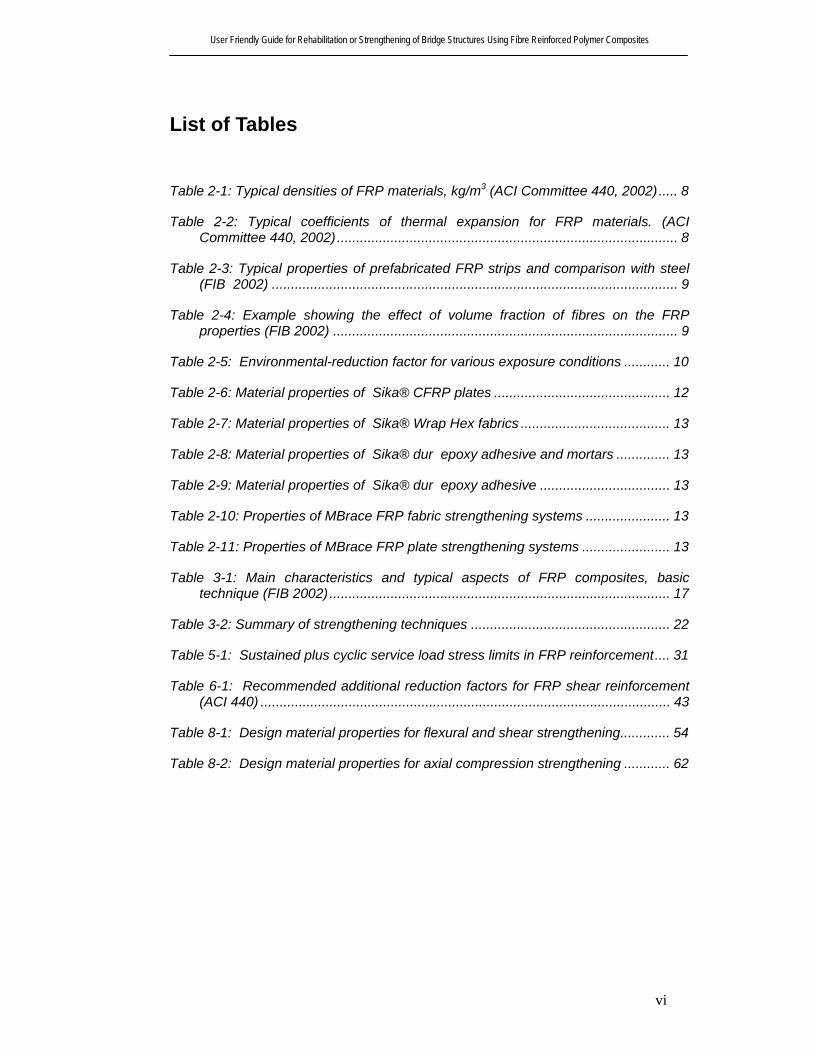
List of Tables
Table 2-1: Typical densities of FRP materials, kg/m3 (ACI Committee 440, 2002)..... 8
Table 2-2: Typical coefficients of thermal expansion for FRP materials. (ACI Committee 440, 2002) ......................................................................................... 8
Table 2-3: Typical properties of prefabricated FRP strips and comparison with steel (FIB 2002) .......................................................................................................... 9
Table 2-4: Example showing the effect of volume fraction of fibres on the FRP properties (FIB 2002) .......................................................................................... 9
Table 2-5: Environmental-reduction factor for various exposure conditions ............ 10
Table 2-6: Material properties of Sika® CFRP plates .............................................. 12
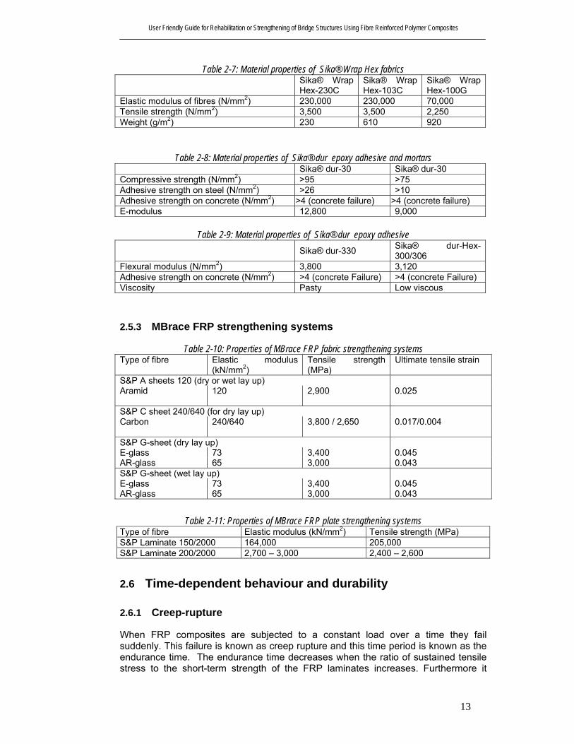
Table 2-7: Material properties of Sika® Wrap Hex fabrics ....................................... 13
Table 2-8: Material properties of Sika® dur epoxy adhesive and mortars .............. 13
Table 2-9: Material properties of Sika® dur epoxy adhesive .................................. 13
Table 2-10: Properties of MBrace FRP fabric strengthening systems ...................... 13
Table 2-11: Properties of MBrace FRP plate strengthening systems ....................... 13
Table 3-1: Main characteristics and typical aspects of FRP composites, basic technique (FIB 2002) ......................................................................................... 17
Table 3-2: Summary of strengthening techniques .................................................... 22
Table 5-1: Sustained plus cyclic service load stress limits in FRP reinforcement.... 31
Table 6-1: Recommended additional reduction factors for FRP shear reinforcement (ACI 440) ........................................................................................................... 43
Table 8-1: Design material properties for flexural and shear strengthening............. 54
Table 8-2: Design material properties for axial compression strengthening ............ 62

User Friendly Guide for Rehabilitation or Strengthening of Bridge Structures Using Fibre Reinforced Polymer Composites
vii
List of Figures
Figure 2-1: Stress strain relations corresponding to various fibre volume fractions Vfib............................................................................................................................ 9
Figure 2-2: Stress-strain diagrams (MBT Australia) .................................................. 11
Figure 3-1: (a) Hand lay-up CFRP sheets. (b) Application of prefabricated strips (FIB 2002) ................................................................................................................. 16
Figure 3-2: Delamination caused by tension failure of the concrete cover ................................... 20
Figure 3-3 : Graphical representation of the guidelines for allowable termination points of a three-ply FRP laminate. ................................................................... 21
Figure 4-1: Strain distribution at Ultimate Limit State in the critical section of strengthened flexural members......................................................................... 25
Figure 5-1: Flexural strengthening of RC beams with CFRP strips (FIB Bulletin 14, 2002) ................................................................................................................. 27
Figure 5-2: Design stress-strain curves of constitutive materials at Ultimate Limit State .................................................................................................................. 27
Figure 5-3: Internal strain and stress distribution for rectangular section under bending moment at ultimate state ..................................................................... 29
Figure 5-4: Elastic strain and stress distribution....................................................... 31
Figure 5-5: Envelope line of the tensile forces ......................................................... 33
Figure 5-6: End anchorage in an un-cracked concrete zone (FIB 2002) ................. 34
Figure 5-7: Element between two subsequent cracks (FIB 2002)............................ 35
Figure 5-8: Diagram of the maximum possible increase in tensile stress between two subsequent cracks (FIB 2002) .......................................................................... 35
Figure 6-1: Schematic illustration of shear failure response ..................................... 40
Figure 6-2: Shear strengthening of: (a) beam end; (b) short column (FIB Bulletin 14, 2002) ................................................................................................................. 41
Figure 6-3: Schematic illustration of reinforced concrete element strengthened in shear with FRP: (a) FRP sheets or fabrics bonded to the web; (b) wrapped or U-shaped FRP (the concept shown in D is applicable to both beams and columns) (FIB Bulletin 14, 2001)....................................................................................... 41
Figure 6-4: CFRP contribution to shear capacity for two different concrete strengths and fully wrapped (properly anchored) versus unwrapped configurations (FIB Bulletin 14, 2002) .............................................................................................. 42

User Friendly Guide for Rehabilitation or Strengthening of Bridge Structures Using Fibre Reinforced Polymer Composites
viii
Figure 6-5: Illustration of the dimensional variables used in shear-strengthening calculations for repair, retrofit or strengthening using FRP laminates ............... 43
Figure 6-6: (a) Torsional and (b) shear cracking. ...................................................... 46
Figure 6-7: Forces carried by the FRP reinforcement ............................................... 46
Figure 7-1: Comparison of confinement actions of steel and FRP materials (FIB Bulletin 14, 2002) .............................................................................................. 48
Figure 7-2: Triaxial state of stress in FRP jackets..................................................... 49
Figure 7-3: Column failures in Kobe 1995 earthquake (EQE 1995).......................... 51
Figure 8-1: Schematic view and cross section of the head stock............................. 53
Figure 8-2: Initial situation ........................................................................................ 54
Figure 8-3: Internal strain and stress distributions for the beam cross section of the headstock .......................................................................................................... 55
Figure 8-4: Flexural strengthening scheme.............................................................. 59
Figure 8-5: Shear strengthening scheme................................................................. 61
Figure 8-6: Cross section of the column ................................................................... 62

User Friendly Guide for Rehabilitation or Strengthening of Bridge Structures Using Fibre Reinforced Polymer Composites
ix
EXECUTIVE SUMMARY A worldwide interest is being generated in the use of fibre reinforced polymer composites (FRP) in rehabilitation of reinforced concrete structures. As a replacement for the traditional steel plates or external post-tensioning in strengthening applications, various types of FRP plates, with their high strength to weight ratio and good resistance to corrosion, represent a class of ideal material in external retrofitting. Within the last ten years, many design guidelines have been published to provide guidance for the selection, design and installation of FRP systems for external strengthening of concrete structures. Use of these guidelines requires understanding of a number of issues pertaining to different properties and structural failure modes specific to these materials. A research initiative funded by the CRC for Construction Innovation was undertaken (primarily at RMIT) to develop a decision support tool and a user friendly guide for use of fibre reinforced polymer composites in rehabilitation of concrete structures. The user guidelines presented in this report were developed after industry consultation and a comprehensive review of the state of the art technology. The scope of the guide was mainly developed based on outcomes of two workshops with Queensland Department of Main Roads (QDMR). The document covers material properties, recommended construction requirements, design philosophy, flexural, shear and torsional strengthening of beams and strengthening of columns. In developing this document, the guidelines published on FIB Bulletin 14 (2002), Task group 9.3, International Federation of Structural Concrete (FIB) and American Concrete Institute Committee 440 report (2002) were consulted in conjunction with provisions of the Austroads Bridge design code (1992) and Australian Concrete Structures code AS3600 (2002). In conclusion, the user guide presents design examples covering typical strengthening scenarios.

User Friendly Guide for Rehabilitation or Strengthening of Bridge Structures Using Fibre Reinforced Polymer Composites
1
1 GENERAL
1.1 Introduction Rehabilitation and upgrading of existing civil engineering infrastructure has been of great importance during the last decades. There are number of situations where the structural capacity of a structure in service needs to be increased. Fibre reinforced composite (FRP) systems can be used for the strengthening or retrofitting of existing concrete structures to resist higher design loads, correct deterioration-related damage, or increase ductility. These advanced composites used in bridge rehabilitation are being developed from fibres, polymers, metals and composites of these materials. While the concept of composites have been used in building industry for several millennia, the application of fibre reinforced polymer (FRP) for rehabilitation and strengthening of reinforced concrete structures is relatively new. Externally bonded FRP systems have been used to strengthen and retrofit existing concrete structures overseas and in Australia, eg, Westgate Bridge and Little Bridge Victoria (Kalra and Neubauer, 2003 and Shepherd and Sarkady 2002). The number of projects utilizing FRP systems has dramatically increased worldwide, from a few ten years ago to several thousand today (Bakis et al. 2002). The FRP composites combine the strength of the fibres with the stability of the polymer resins. They are defined as polymer matrix, that are reinforced with fibres or other reinforcing material with a sufficient aspect ratio (length to thickness) to provide a desirable reinforcing function in one or more directions. The FRP composite materials are different from traditional construction materials such as steel, aluminium and concrete because they are anisotropic; i.e., the properties differ depending on the direction of the fibres. FRP composites gain their strength largely from the fibres, which are usually glass, carbon, or Aramid fibre. FRP materials are lightweight, non-corrosive, non-magnetic and exhibit high tensile strength. Additionally, these materials are readily available in several forms ranging from factory made laminates to dry fibre sheets that can be wrapped to conform to the geometry of a structure before adding the polymer resin. Although the fibres and resins used in an FRP system are relatively expensive compared with traditional strengthening materials like concrete and steel, labour and equipment costs to install FRP systems are often lower. FRP systems can also be used in areas with limited access where traditional techniques would be difficult to implement. Due to the characteristics of FRP materials, behaviour of FRP strengthened members, and various issues regarding the use of externally bonded reinforcement, the development of design guidelines for FRP system is ongoing in Europe, Japan, Canada and the United States. Within the last ten years, many design guidelines have been published to provide guidance for the selection, design and installation of FRP systems for external strengthening of concrete structures. However there is still little independent user friendly guidance on the design and construction of the FRP strengthening systems. Some FRP suppliers provide limited advice but this tends to be system specific and may not be compatible with Australian design codes. Because of this lack of design and construction guidance, a user friendly guide on rehabilitation and strengthening of reinforced concrete bridge structures is being developed as part of the CRC-Construction Innovation funded project of “Decision Support Tool in Rehabilitation of Concrete Infrastructures”, which would be applicable to all types of FRP and all strengthening systems, and set in the context of the

User Friendly Guide for Rehabilitation or Strengthening of Bridge Structures Using Fibre Reinforced Polymer Composites
2
Australian codes and standards. Set in the context of limit state philosophy, the guide provides design guidance on flexural and shear strengthening of beams and columns, and flexural strength, axial compressive strength and ductility enhancement of columns. The construction procedures are also briefly explained including material types and properties, field applications, workmanship and installation.
1.2 Scope and Limitations This report offers general information on the use, engineering, design, construction and inspection of externally bonded FRP composites strengthening systems. The design procedures are the key feature of the guide, which may be applicable to all FRP materials and strengthening techniques. The procedures are based on generally accepted principles, and in line with the approaches developed elsewhere based on extensive research, particularly as in the USA and Europe. The material and physical properties of FRP materials and manufacturing methods are reviewed in so far as they have a direct impact on the design and construction of the FRP strengthening system. Information on the properties of commercially available materials is also presented. Surface preparation of the substrate concrete and installation of FRP are vital aspects and have therefore been covered in the guide. Some guidance in quality control and inspection and monitoring are included. It is essential to assess suitability of an FRP system for a particular application. A condition assessment of the existing structure should be performed and the best treatment option should then be determined based on the assessment (ACI, 440, 2002). The condition assessment can be perform based on AS 3600(2002), Austroads Bridge design code (1992) and other related Australian codes and standards. The recommended assessment procedures are outlined in the user guide. FRP materials should not be selected as a blind replacement of conventional strengthening or rehabilitation systems in structural intervention applications. The application of FRP strengthening system should be based on consideration of several factors, including not only mechanical performance aspects, but also constructability, long-term durability, and availability of the material. The durability and long term performance of FRP materials have been subject of much research, however this research remains on-going. Long-term field data are not yet available, and it is still difficult to predict accurately the life of FRP strengthening systems. The environment degradation and long term durability may be considered by using reduction factors for various environments. Additionally, the coupling effect of environmental conditions and loading conditions still requires further study. Caution is advised in applications where the FRP are subjected simultaneously to extreme environmental and stress conditions. Many issues regarding bonding of the FRP system to the substrate remain the focus of a great deal of research. There are many different debonding failure modes in shear and bending that can govern the strength of an FRP strengthened member. Most of the debonding modes are covered in this report; more accurate methods of predicting debonding may be still needed.
User Friendly Guide for Rehabilitation or Strengthening of Bridge Structures Using Fibre Reinforced Polymer Composites
3
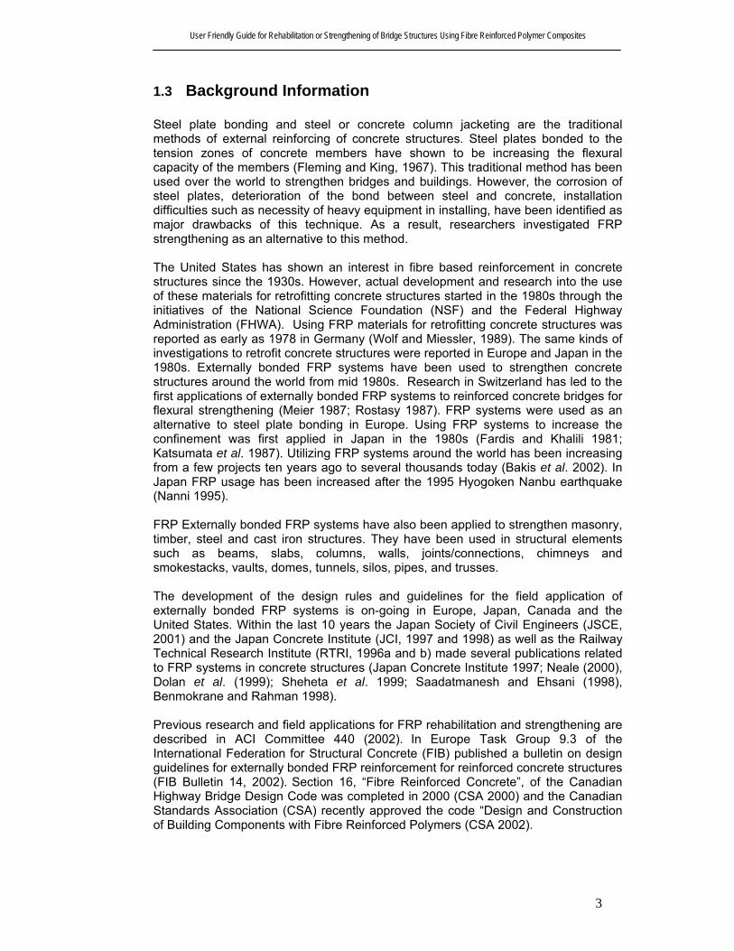
1.3 Background Information Steel plate bonding and steel or concrete column jacketing are the traditional methods of external reinforcing of concrete structures. Steel plates bonded to the tension zones of concrete members have shown to be increasing the flexural capacity of the members (Fleming and King, 1967). This traditional method has been used over the world to strengthen bridges and buildings. However, the corrosion of steel plates, deterioration of the bond between steel and concrete, installation difficulties such as necessity of heavy equipment in installing, have been identified as major drawbacks of this technique. As a result, researchers investigated FRP strengthening as an alternative to this method. The United States has shown an interest in fibre based reinforcement in concrete structures since the 1930s. However, actual development and research into the use of these materials for retrofitting concrete structures started in the 1980s through the initiatives of the National Science Foundation (NSF) and the Federal Highway Administration (FHWA). Using FRP materials for retrofitting concrete structures was reported as early as 1978 in Germany (Wolf and Miessler, 1989). The same kinds of investigations to retrofit concrete structures were reported in Europe and Japan in the 1980s. Externally bonded FRP systems have been used to strengthen concrete structures around the world from mid 1980s. Research in Switzerland has led to the first applications of externally bonded FRP systems to reinforced concrete bridges for flexural strengthening (Meier 1987; Rostasy 1987). FRP systems were used as an alternative to steel plate bonding in Europe. Using FRP systems to increase the confinement was first applied in Japan in the 1980s (Fardis and Khalili 1981; Katsumata et al. 1987). Utilizing FRP systems around the world has been increasing from a few projects ten years ago to several thousands today (Bakis et al. 2002). In Japan FRP usage has been increased after the 1995 Hyogoken Nanbu earthquake (Nanni 1995). FRP Externally bonded FRP systems have also been applied to strengthen masonry, timber, steel and cast iron structures. They have been used in structural elements such as beams, slabs, columns, walls, joints/connections, chimneys and smokestacks, vaults, domes, tunnels, silos, pipes, and trusses. The development of the design rules and guidelines for the field application of externally bonded FRP systems is on-going in Europe, Japan, Canada and the United States. Within the last 10 years the Japan Society of Civil Engineers (JSCE, 2001) and the Japan Concrete Institute (JCI, 1997 and 1998) as well as the Railway Technical Research Institute (RTRI, 1996a and b) made several publications related to FRP systems in concrete structures (Japan Concrete Institute 1997; Neale (2000), Dolan et al. (1999); Sheheta et al. 1999; Saadatmanesh and Ehsani (1998), Benmokrane and Rahman 1998). Previous research and field applications for FRP rehabilitation and strengthening are described in ACI Committee 440 (2002). In Europe Task Group 9.3 of the International Federation for Structural Concrete (FIB) published a bulletin on design guidelines for externally bonded FRP reinforcement for reinforced concrete structures (FIB Bulletin 14, 2002). Section 16, “Fibre Reinforced Concrete”, of the Canadian Highway Bridge Design Code was completed in 2000 (CSA 2000) and the Canadian Standards Association (CSA) recently approved the code “Design and Construction of Building Components with Fibre Reinforced Polymers (CSA 2002).

User Friendly Guide for Rehabilitation or Strengthening of Bridge Structures Using Fibre Reinforced Polymer Composites
4
1.4 Structural Assessment Identification of the deficiencies of the bridge structure is the first step in addressing the issue of rehabilitation. This requires clear identification of performance requirements of the bridge structure and then evaluating the performance based on existing information on the bridge. Condition assessment of the structure is the first step in determining the rehabilitation methodology. Clear identification of the performance level needed and the structural deficiency requires design load definition, definition of traffic, material properties and design documentation of the existing structure. Project specifications and identified strategic function and level of use of the route can be used to establish some of the above information. Evaluation of the structure should commence by conducting a systematic field assessment and recording details of previous repair or rehabilitation tasks undertaken and accident and traffic overloading data if available. This would be followed by a structural analysis and design calculations complying with the recommendations of the relevant codes and standards. To assess suitability of an FRP system for a particular application, the engineer should perform condition assessment of the existing structure based on AS 3600 (2002) and Austroads Bridge Design code (1992). The overall evaluation should include a thorough field inspection, review of existing design and as built documents, and a structural analysis. Existing construction documents for the structure should be reviewed, including the design drawings, project specifications, as built information, field test reports, past repair documentation, and maintenance history documentation. In addition, field investigation should verify the following:
• Existing dimensions of the structural members; • Location, size, and cause of cracks and spalls; • Location and extent of corrosion of reinforcing steel; • Quantity and location of existing reinforcing steel; • In-place compressive strength of concrete; and • Soundness of concrete, especially the concrete cover, in all areas where the
FRP system is to be bonded to the concrete. The load carrying capacity of the existing structure should be then determined in accordance with the relevant Australian standards and based on the information gathered in the field investigation, review of design calculations and drawings, and as determined by analytical or other suitable methods. Load tests or other non-destructive test methods can be incorporated into the overall evaluation process if deemed appropriate.
1.5 Applications and Use FRP composites have found their way as strengthening materials of reinforced concrete elements (such as beams, slabs, columns etc.) in thousands of applications worldwide, where conventional strengthening techniques could be problematic. The range of applicability of externally bonded reinforcement in reinforced concrete structures is increasing constantly. Recent developments related to materials, methods and techniques for structural strengthening and rehabilitation of the deteriorated bridges have been enormous. The reasons why FRP composites are increasingly used as strengthening materials of reinforced concrete elements may be summarized as follows:

User Friendly Guide for Rehabilitation or Strengthening of Bridge Structures Using Fibre Reinforced Polymer Composites
5
• Immunity in corrosion; • Low weight; • Easier application in confined space; • Elimination of the need for scaffolding and reduction in labour costs or
stopping traffic and bridge operation; • Very high tensile strength (both static and long term, for certain types of FRP
material); • Large deformation capacity; and • Unlimited availability in FRP sizes, geometry and dimensions.
In regards to these advantages, uses of FRP strengthening systems make the rehabilitation and strengthening of bridges more achievable.
1.6 Commercially Available Externally Bonded FRP Systems
FRP systems can be categorized based on installation and construction methods. Common FRP system forms may be listed as follows:
1.6.1 Wet lay-up systems
In wet lay-up systems, the saturating resin, along with the compatible primer and putty, is used to impregnate and bond the FRP dry unidirectional or multidirectional fibre sheets or fabrics sheets to the concrete surface.
1.6.2 Prepreg systems In prepreg systems, the uncured unidirectional or multidirectional fibre sheets or fabrics bond to the existing concrete with or without an additional resin application, after they are pre-impregnated with a saturating resin in the manufacturer’s facility. Prepreg systems are saturated off-site and, like wet lay-up systems, cured-in-place.
1.6.3 Precured systems
In precured systems, the factory fabricated FRP strips or sheets bond to the concrete surface using an adhesive along with the primer and putty. The system manufacturer should be consulted for recommended installation procedures.

User Friendly Guide for Rehabilitation or Strengthening of Bridge Structures Using Fibre Reinforced Polymer Composites
6
2 MATERIAL In this chapter, the physical and mechanical properties of FRP composites are presented. The characteristics of FRP composites depend on many factors such as type of fibre, its orientation and volume, type of resin used and quality control used during the manufacturing process. It is possible to obtain the characteristics of commercially available FRP composites from the manufacturer. However, some generic material characteristics are described in this chapter. FRP composite materials for strengthening of civil engineering structures are available today mainly in the form of:
• thin unidirectional strips (with thickness in the order of 1 mm) made by pultrusion; and
• flexible sheets or fabrics, made of fibres in one or at least two different directions, respectively (and sometimes pre-impregnated with resin).
FRP systems come in a variety of forms, including wet lay-up systems and precured systems. The FRP system and its form should be selected based on acceptable transfer of structural loads and ease and simplicity of application. The manufacture of FRP materials is outlined and some general guidance on selection of FRP system and materials for particular strengthening applications are also provided. Indicative physical and mechanical material properties of some FRP prefabricated strips and fibres are included in the guide. The other related aspects of FRP materials such as durability, fire and electricity resistance, safety and environmental impact on material properties for different types of fibres are also discussed.
2.1 Constituent Materials There are several constituent materials in commercially available FRP repair systems such as resins, primers, putties, saturants, adhesives, and fibres.
2.1.1 Resins
A large variety of resins are used with FRP systems. The most commonly used resins can normally be used in different environmental conditions. However as shown by the ACI Committee 440 (2002), FRP system manufacturers use resins that have the following characteristics: • Compatibility with, and adhesion to, the concrete substrate;
• Compatibility with, and adhesion to, the FRP composite system;
• Resistance to environmental effects, including but not limited to, moisture, salt water, temperature extremes, and chemicals normally associated with exposed concrete;
• Filling ability;
• Workability;
• Pot life consistent with the application;

User Friendly Guide for Rehabilitation or Strengthening of Bridge Structures Using Fibre Reinforced Polymer Composites
7
• Compatibility with and adhesion to the reinforcing fibre; and
• Development of appropriate mechanical properties for the FRP composite.
2.1.1.1 Primer The primer is used to penetrate the surface of the concrete, providing an improved adhesive bond for the saturating resin or adhesive.
2.1.1.2 Putty fillers The putty is used to fill small surface voids in the substrate, such as bug holes, and to provide a smooth surface to which the FRP system can bond. Filled surface voids also prevent bubbles from forming during curing of the saturating resin.
2.1.1.3 Saturating resin The saturating resin is used to impregnate the reinforcing fibres, fix them in place, and provide a shear load path to effectively transfer load between fibres. The saturating resin also serves as the adhesive for wet lay-up systems, providing a shear load path between the previously primed concrete substrate and the FRP system.
2.1.1.4 Adhesives Adhesives are used to bond pre-cured FRP laminate systems to the concrete substrate. The adhesive provides a shear load path between the concrete substrate and the FRP reinforcing laminate. Adhesives are also used to bond together multiple layers of precured FRP laminates.
2.1.1.5 Protective coatings The protective coating may be used to protect the bonded FRP reinforcement from potentially damaging environmental effects. Coatings are typically applied to the exterior surface of the cured FRP system after the adhesive or saturating resin has cured.
2.1.2 Fibres
Continuous glass, aramid, and carbon fibres are common reinforcements used with FRP systems. The fibres give the FRP system its strength and stiffness.
2.2 Physical Properties
2.2.1 Density
The densities of FRP composites with Glass, Carbon and Aramid are shown in Table 2-1 (ACI Committee 440, 2002). The density of steel is also presented there as comparison. It is clearly seen from the Table that density of FRP composites are four to six times lower than that of steel. The reduced density is a desirable property as it reduces transportation and handling cost and additional dead load on structure.

User Friendly Guide for Rehabilitation or Strengthening of Bridge Structures Using Fibre Reinforced Polymer Composites
8
Table 2-1: Typical densities of FRP materials, kg/m3 (ACI Committee 440, 2002)
Steel GFRP CFRP AFRP 7,900 1,200 – 2,100 1,500 – 1,600 1,200 – 1,500
2.2.2 Coefficient of thermal expansion
Table 2-2 (ACI Committee 440, 2002) shows the coefficients of thermal expansion for typical unidirectional FRP materials. It is clearly shown that it changes in the longitudinal and transverse directions and also depending on the type of fibre, volume of fibre and resin. The coefficient of thermal expansion of concrete ranges from 7×10⁻⁶ to 11×10-6/C and is usually assumed to be isotropic. Steel has an isotropic coefficient of thermal expansion of 11.7×10⁻⁶/C.
Table 2-2: Typical coefficients of thermal expansion for FRP materials. (ACI Committee 440, 2002) Coefficient of thermal expansion, ×10-6/C
Direction GFRP CFRP AFRP
Longitudinal 6 to 10 -1 to 0 -6 to –2
Transverse 19 to 23 22 to 50 60 to 80
2.3 Mechanical Properties FRP materials are composed of a number of continuous, directionalized, nonmetallic fibres, bundled in a resin matrix. Normally, the volume fraction of fibres in FRP strips is about 50-70% and that in FRP sheets is about 25-35%. Fibres are the principal stress bearing constituents, while the resin transfers stresses among fibres and protects them. If these volume fractions and properties of constituent materials (fibres and matrix) are known for a particular FRP composite then mechanical properties can be obtained as shown in FIB Bulletin 14 (2002).
mmfibfibf VEVEE += 2-1
mmfibfibf VfVff +≈ 2-2 where, Ef = Young’s modulus of FRP in fibre direction, Efib = Young’s modulus of fibres, Em= Young’s modulus of matrix, Vfib = volume fraction of fibres, Vm = volume fraction of matrix, ff = tensile strength of FRP in fibre direction, ffib = tensile strength of fibres and, fm = tensile strength of matrix. Note that in the above equations Vfib + Vm = 1. Also, typical values for the volume fraction of fibres in prefabricated strips are in the order of 0.50 – 0.65. FIB Bulletin 14 (2002) shows the properties of commercially available FRP prefabricated strips (Table 2-3). Normally for these strips, the manufacturer provides the material properties.

User Friendly Guide for Rehabilitation or Strengthening of Bridge Structures Using Fibre Reinforced Polymer Composites
9
Table 2-3: Typical properties of prefabricated FRP strips and comparison with steel (FIB 2002) Material Elastic modulus
(GPa) - Ef Tensile strength (MPa) - ff
Ultimate tensile strain (%) - εfu
Prefabricated strips Low modulus CFRP High modulus CFRP
170 300
2800 1300
1.6 0.5
Mild steel 200 400 25 (Yield strain = 0.2 %)
In in-situ resin impregnated systems, the final FRP thickness and thus the fibre volume is uncertain. Therefore the composite material properties based on the properties of fibres and matrix may not be appropriate. Sometimes manufacturers provide the material properties for the bare fibres. There is a strong relationship between the fibre volume fraction and the FRP properties to be used in the property calculation of mechanical properties of FRP composite. This is shown in Table 2-4 and Figure 2-1.
Table 2-4: Example showing the effect of volume fraction of fibres on the FRP properties (FIB 2002) Properties for constituent materials of FRP composite: Fibre: Young’s modulus: 220 GPa Tensile strength: 4000 MPa Matrix: Young’s modulus: 3 GPa Tensile strength: 80 MPa Cross sectional area FRP properties Failure load Afib (mm2)
Am (mm2)
A*f (mm2)
Vfib (%)
Ef (MPa) Eq. (2-1)
ff (MPa) Eq. (2-1)
Ultimate strain (%)
(kN) (%)
70 0 70 100 220,000 4000 1.818 280.0 100.0 70 30 100 70 154,900 2824 1.823 283.4 100.9 70 70 140 50 111,500 2040 1.830 285.6 102.0 * In the case of a strip with a width of 100 mm dividing this value by 100 mm gives the thickness of the strip. It can be seen that for a constant amount of fibre volume, an increase in the amount of resin has a minor effect on the failure load. However, the FRP composite properties are strongly influenced by the matrix proportion.
Figure 2-1: Stress strain relations corresponding to various fibre volume fractions Vfib
0
1000
2000
3000
4000
0 0.5 1 1.5 2
Strain (%)
Stre
ss (M
Pa)
Vfib=100% and tf=0.7 mm
Vfib=70% and tf=1.0 mm
Vfib=50% and tf=1.4 mm
In case of an uncertainty of the FRP thickness (in-situ resin impregnated systems), it is convenient to perform the calculations based on the fibre properties and fibre cross sectional area provided that the material properties and the thickness supplied by the manufacturer are used instead of the actual thickness realized. In this situation the second part of Equations (2-1) and (2-2) may be ignored and the resulting property (elastic modulus, tensile strength) should be multiplied by a reduction factor r. This factor r should be supplied by the supplier based on test results. Alternatively the

User Friendly Guide for Rehabilitation or Strengthening of Bridge Structures Using Fibre Reinforced Polymer Composites
10
FRP supplier can provide the properties of in-situ impregnated system (thickness, elastic modulus, and tensile strength) based on test results.
2.4 Design Material Properties The material properties reported by manufacturers do not normally consider the effect of long-term exposure of the FRP materials to various types of environmental conditions. The long-term exposure of the FRP materials to the environment can reduce the tensile strength, creep-rupture, fatigue endurance and other material characteristics. Hence, the design material properties should be reduced based on the environmental exposure condition. The design ultimate tensile strength, rupture strain and modulus of elasticity then may be calculated using Eqs (2-3) and (2-4).
*fuEfu fCf = 2-3
*fuEfu C εε = 2-4
fu
fuf
fE
ε= 2-5
* The material properties reported by manufacturer The environmental-reduction factor, CE, for various exposure conditions and different types of FRP are given in Table 2-5 (ACI 440, 2002).
Table 2-5: Environmental-reduction factor for various exposure conditions
Exposure Condition Fibre and resin type Environmental-reduction factor, CE
Carbon/epoxy 0.95
Glass/epoxy 0.75 Interior exposure
Aramid/epoxy 0.85
Carbon/epoxy 0.85
Glass/epoxy 0.65 Exterior exposure (bridges, piers, and enclosed parking garages)
Aramid/epoxy 0.75
Carbon/epoxy 0.85
Glass/epoxy 0.5 Aggressive environment (chemical plants and waste water treatments)
Aramid/epoxy 0.7

User Friendly Guide for Rehabilitation or Strengthening of Bridge Structures Using Fibre Reinforced Polymer Composites
11
2.5 Commercially Available Externally Bonded FRP in Australia
Composite materials for strengthening structures are available in the form of unidirectional thin strips made by pultrusion or sheets or fabrics made of fibres in at least one or two different directions. Major suppliers of FRP systems in Australia are Master Builders Technologies (MBT) and Sika® Services Corporate Construction. MBT supplies two MBrace Composite Strengthening Systems. The first one is the MBrace FRP fabric (sheet) materials including carbon, aramid and glass fibres while the other system is MBrace S&P CFK laminate strip (plate) (carbon fibre laminate materials). Sika® CarboDur composite strengthening systems supply flexural strengthening products (plates), shear strengthening products (L-shaped strips) and shear strengthening and confinement products (flexible sheets). The Sika® products include carbon, aramid and glass fibres. These commercially available composite strengthening systems are described briefly in the following sections.
2.5.1 MBrace composite strengthening systems (MBT Australia)
The MBrace Composite Strengthening System comprises a family of lightweight FRP materials. They are externally bonded to the surface of structures to enhance the strength. These systems provide very high tensile strength and are used for flexural and shear reinforcement and axial compression confinement of concrete, masonry and timber elements. The MBT-MBrace sheets (either uni-directional or bi-directional) can be applied as dry and wet lay ups and also as pre-impregnated Prepegs. Types of fibres used in MBrace FRP systems are carbon, aramid and glass (uncoated E-glass which corrodes in alkaline environment and Alkali resistant glass-AR glass). The stress-strain diagram for these fibres is shown in Figure 2-2.
Figure 2-2: Stress-strain diagrams (MBT Australia)
s
The basic fibres in MBrace FRP systems are embedded in a polymer matrix where the arrangement of fibres can be either unidirectional or bidirectional.
2.5.1.1 MBrace FRP fabric (sheet) materials MBrace FRP fabric sheets can be stretched or woven and uni-directional or bi-directional as follows;
User Friendly Guide for Rehabilitation or Strengthening of Bridge Structures Using Fibre Reinforced Polymer Composites
12
Stretched sheets, Uni-directional arrangement:
In the stretched sheets fibres are bonded to a tight mesh and parallel fibres are stretched. Therefore these sheets have high elastic modulus. These are more suitable for increasing the structural capacity of an element.
Woven sheets, Bi-directional arrangement:
Woven sheets are produced by weaving and the arrangement of fibres is bi directional. These sheets are less suitable for increasing the structural capacity of an element as the fibres are slightly wavy. These bi directional sheets are more suitable for increasing the ductility of a structural component.
Uni-directional and bi-directional MBT-MBrace FRP sheets
Either cold curing epoxy resin matrix or the thermally curing epoxy resin matrix is used to ensure the load transfer from the sheets to the substrate.
Cold curing epoxy resin matrix:
Uni-directional and bi-directional sheets are applied as a dry lay up if the weight is less than 400 gm/m2. In this case the cold curing epoxy resin is rolled onto the structural element and dry sheet is applied into the matrix. Stretched and woven sheets are applied as a wet lay up if the weight is less than 400-800 gm/m2. Contrary to the dry lay up situation, in this case the sheets are impregnated with the cold curing epoxy matrix and then applied wet to the structural element.
Thermally curing epoxy resin matrix:
The uni-directional and bi-directional sheets are impregnated with the thermally curing epoxy adhesive at the manufacturer’s facility. Thermal curing is done by applying additional heat to the epoxy resin on the element. This method is called a Prepeg system.
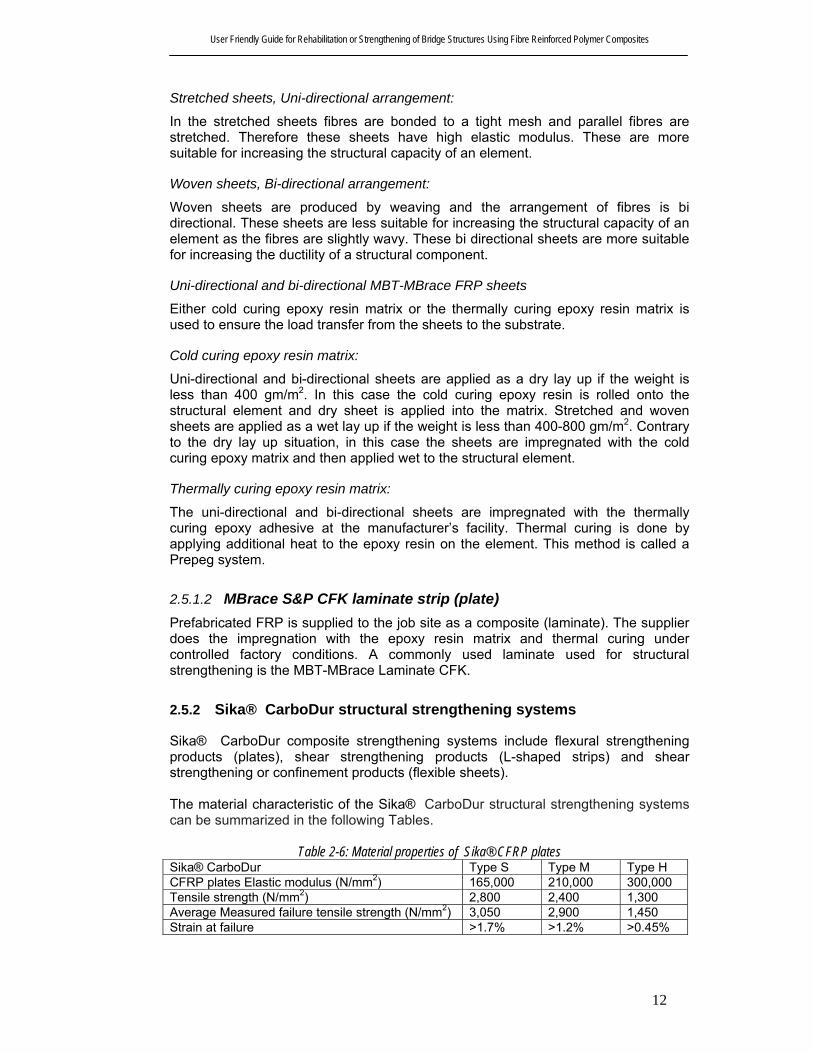
2.5.1.2 MBrace S&P CFK laminate strip (plate) Prefabricated FRP is supplied to the job site as a composite (laminate). The supplier does the impregnation with the epoxy resin matrix and thermal curing under controlled factory conditions. A commonly used laminate used for structural strengthening is the MBT-MBrace Laminate CFK.
2.5.2 Sika® CarboDur structural strengthening systems
Sika® CarboDur composite strengthening systems include flexural strengthening products (plates), shear strengthening products (L-shaped strips) and shear strengthening or confinement products (flexible sheets). The material characteristic of the Sika® CarboDur structural strengthening systems can be summarized in the following Tables.
Table 2-6: Material properties of Sika® CFRP plates Sika® CarboDur Type S Type M Type H CFRP plates Elastic modulus (N/mm2) 165,000 210,000 300,000 Tensile strength (N/mm2) 2,800 2,400 1,300 Average Measured failure tensile strength (N/mm2) 3,050 2,900 1,450 Strain at failure >1.7% >1.2% >0.45%
User Friendly Guide for Rehabilitation or Strengthening of Bridge Structures Using Fibre Reinforced Polymer Composites
13
Table 2-7: Material properties of Sika® Wrap Hex fabrics Sika® Wrap
Hex-230C Sika® Wrap Hex-103C
Sika® Wrap Hex-100G
Elastic modulus of fibres (N/mm2) 230,000 230,000 70,000 Tensile strength (N/mm2) 3,500 3,500 2,250 Weight (g/m2) 230 610 920
Table 2-8: Material properties of Sika® dur epoxy adhesive and mortars Sika® dur-30 Sika® dur-30 Compressive strength (N/mm2) >95 >75 Adhesive strength on steel (N/mm2) >26 >10 Adhesive strength on concrete (N/mm2) >4 (concrete failure) >4 (concrete failure) E-modulus 12,800 9,000
Table 2-9: Material properties of Sika® dur epoxy adhesive Sika® dur-330 Sika® dur-Hex-
300/306 Flexural modulus (N/mm2) 3,800 3,120 Adhesive strength on concrete (N/mm2) >4 (concrete Failure) >4 (concrete Failure) Viscosity Pasty Low viscous
2.5.3 MBrace FRP strengthening systems
Table 2-10: Properties of MBrace FRP fabric strengthening systems Type of fibre Elastic modulus
(kN/mm2) Tensile strength (MPa)
Ultimate tensile strain
S&P A sheets 120 (dry or wet lay up) Aramid 120 2,900 0.025 S&P C sheet 240/640 (for dry lay up) Carbon 240/640 3,800 / 2,650 0.017/0.004 S&P G-sheet (dry lay up) E-glass 73 3,400 0.045 AR-glass 65 3,000 0.043 S&P G-sheet (wet lay up) E-glass 73 3,400 0.045 AR-glass 65 3,000 0.043
Table 2-11: Properties of MBrace FRP plate strengthening systems Type of fibre Elastic modulus (kN/mm2) Tensile strength (MPa) S&P Laminate 150/2000 164,000 205,000 S&P Laminate 200/2000 2,700 – 3,000 2,400 – 2,600
2.6 Time-dependent behaviour and durability
2.6.1 Creep-rupture
When FRP composites are subjected to a constant load over a time they fail suddenly. This failure is known as creep rupture and this time period is known as the endurance time. The endurance time decreases when the ratio of sustained tensile stress to the short-term strength of the FRP laminates increases. Furthermore it

User Friendly Guide for Rehabilitation or Strengthening of Bridge Structures Using Fibre Reinforced Polymer Composites
14
decreases with adverse environmental conditions such as high temperature, high alkalinity, freezing-thawing cycles and wet-dry cycles. As stated in ACI Committee 440 (2002) the relationship between creep rupture strength and the logarithm of time for FRP bars is linear. The ratios of stress level at creep-rupture after 500,000 hours to the initial ultimate strength of the GFRP, AFRP, and CFRP bars were extrapolated to be 0.3, 0.47, and 0.91, respectively (Yamaguchi et al. 1997). Similar values have been determined elsewhere (Malvar 1998). The vulnerability of carbon, aramid and glass fibres to creep rupture is increasing respectively.
2.6.2 Fatigue
Fatigue behaviour and life prediction of stand alone FRP materials have been studied in the last 30 years (American National Research Council 1991). In these studies aerospace materials were the primary subject of investigation. Based on the test results some general observations on the fatigue behaviour have been made. Test conditions that raise the temperature and moisture content of FRP materials generally degrade the ambient environment fatigue behaviour. Of all FRP composite type, CFRP is least susceptible to fatigue failure having a survival limit of 60 to 70% (one million cycles) of the initial static ultimate strength of CFRP. In a stress versus logarithm of the number of cycles at failure graph, the downward slope of CFRP is about 5% of the initial static ultimate strength per decade of logarithmic life. Fatigue strength of CFRP is not normally affected by moisture and temperature exposures of concrete structures unless the resin or fibre/resin interface has suffered substantial deterioration due to the environment. Individual glass fibres showed a delayed rupture caused by stress corrosion under ambient environment laboratory conditions (Mandell 1982). A cyclic tensile fatigue effect of approximately 10% loss in the initial static strength per decade of logarithmic lifetime is observed for GFRP composites (Mandell 1982). Generally, no clear fatigue limit can be defined. Environmental factors such as moisture, alkaline, and acidic solutions can play an important role in the fatigue behaviour of glass fibres. Aramid fibres exhibit good fatigue behaviour and the tension-tension fatigue behaviour of an impregnated aramid fibre strand is excellent. Strength degradation per decade of logarithmic lifetime is approximately 5 to 6% (Roylance and Roylance 1981). Commercial AFRP tendons for concrete have a survival limit of 54 to 73% of the ultimate tensile strength in two million years (Odagiri et al. 1997).
2.6.3 Durability
The tensile strengths provided by the manufacturers of FRP systems are based on tests conducted in a laboratory environment, which does not simulate the real environment conditions. However, the mechanical properties of FRP systems are reduced with many factors such as the adverse environmental exposure (high temperature, humidity and chemicals), the duration of exposure, resin and fibre type and resin curing method (see also Table 2-5).

User Friendly Guide for Rehabilitation or Strengthening of Bridge Structures Using Fibre Reinforced Polymer Composites
15
3 RECOMMENDED CONSTRUCTION REQUIREMENTS
FRP system shipping, storage and installation procedures are normally developed by the system manufacturer. The procedure differs between systems and even within a system depending on the condition of the structure. This chapter gives general guidelines for FRP system installation based on international guidelines (FIB Bulletin 14, 2002 and ACI Committee 440, 2002) as well as procedures developed by Australian manufacturers.
3.1 Shipping and Storage
3.1.1 Shipping
FRP materials should be labelled and packaged and shipped according to all applicable Australian packaging and shipping codes and regulations. The corrosive, flammable, or poisonous materials should be labelled and classified under “Hazardous Materials Regulations”. Type and material identity of FRP laminates is usually stamped on each length module and identification of FRP wrap rolls is labelled on each roll.
3.1.2 Storage
FRP system constituent materials should be stored in a manner that preserves the properties and maintains the safety in accordance with manufacturer’s recommendations. Material safety data sheets (MSDS) for all FRP constituent materials and components should be assessable at the job site, and may be obtained from the manufacturers. The handling requirements and potential hazards of the FRP materials may be found in information sources, such as organization literature and guides or OHS guides.
3.2 Techniques for FRP Strengthening The strengthening techniques concern the application of FRP as structural reinforcement bonded to an existing concrete substrate structure. The technique can be used under different conditions and at different locations of the structural member taking into account all specifications and requirements.
3.2.1 Basic technique
The most widely used FRP strengthening technique is the manual application of wet lay-up (hand lay-up) or prefabricated systems using cold cured adhesive bonding. The crutial feature of this technique is that the fibres of externally bonded FRP composites are in parallel as practicable with the direction of principal tensile stresses. Typical applications of the hand lay-up and prefabricated systems are illustrated in Figure 3-1. The basic technique of FRP strengthening described here refers to the manual application of FRP reinforcement to an existing member. A two-part cold cured bonding agent is used to achieve bonding.

User Friendly Guide for Rehabilitation or Strengthening of Bridge Structures Using Fibre Reinforced Polymer Composites
16
Figure 3-1: (a) Hand lay-up CFRP sheets. (b) Application of prefabricated strips (FIB 2002)
The basic technique involves three acting elements, defined as follows.
3.2.1.1 Substrate FRP composite is bonded to an existing structure to enhance its strength. The behaviour of the strengthened structure heavily depends on a good concrete substrate and the preparation of the concrete surface. As shown by FIB Bulletin 14 (2002) the initial conditions of the concrete surface in terms of strength, carbonation, unevenness, imperfections, cracks, type and possible corrosion of internal steel reinforcement, humidity, level of chloride and sulphate ions, etc. should be known.
3.2.1.2 Adhesive/Resin A suitable adhesive/resin should be selected for a particular FRP strengthening system. This is normally specified by the manufacturer to meet all the requirements regarding the installation system. The bonding agent normally ensures the bond between the substrate and the FRP reinforcement. It may have to impregnate “wet lay-up” types of FRP systems depending on the type of FRP reinforcement.
3.2.1.3 FRP reinforcement Depending on the application of the FRP composites, they can be categorized as follows. - “Prefab” or “pre-cured” strips or laminates These FRP strips are provided as fully cured composites, which have their final shape, strength and stiffness. They are mostly available as thin strips or laminates (thickness about 1.0 to 1.5 mm), similar to steel plates. For this type of strip the adhesive provides the bond between the strip and the concrete only. - “Wet lay-up (hand lay-up)” or “cured in situ” sheets or fabrics These FRP materials are available as “dry fibre”, which means that no resin is inside the FRP before applying, or “prepreg”, having a very small amount of resin already inside the sheet before applying. In the latter case, the amount of resin is not sufficient for polymerization. For these types of sheets the application of the adhesive is required to both bond the sheet to the concrete and to impregnate the sheet. The main characteristic and typical aspect of FRP composites are presented inTable 3-1.

User Friendly Guide for Rehabilitation or Strengthening of Bridge Structures Using Fibre Reinforced Polymer Composites
17
Table 3-1: Main characteristics and typical aspects of FRP composites, basic technique (FIB 2002)
Pre-cured (Prefab)
Cured in situ (Wet lay-up)
Shape Strips or laminates Sheets or fabrics Thickness About 1.0 to 1.5 mm About 0.1 to 0.5 mm Use Simple bonding of the factory
made elements with adhesive Bonding and impregnation of the sheets or fabrics with resin (shaped and cured in-situ)
If not pre-shaped only for flat surfaces
Regardless of the shape, sharp corners should be rounded
Thixotropic adhesive for bonding Low viscosity resin for bonding and impregnation
Normally one layer, multiple layers possible
Often multiple layers
Stiffness of strip and use of thixotropic adhesive allow for certain surface unevenness
Often a putty is needed to prevent debonding due to unevenness
Simple in use, higher quality guarantee (prefab system)
Very flexible in use, needs rigorous quality control
Typical application aspects
Quality control (wrong application and bad workmanship = loss of composite action between FRP externally bonded reinforcement and substrate/structure, lack of long term integrity of the system etc)
3.3 Temperature, Humidity, and Moisture Considerations Surface temperature of the concrete, temperature, relative humidity of air before and during installation can affect the FRP strengthening procedure. Primers, saturating resins, and adhesives generally should not be applied to cold or frozen surfaces. If the temperature of concrete surface is below a minimum level as proposed by the manufacturer, an auxiliary heat source must be used to increase the surface and air temperature. If this is not used, improper saturation of the fibres and curing of the resin constituent materials may occur. The heating device should not contaminate uncured FRP system. It is a general practice to apply resins and adhesives to dry and clean concrete surface. If FRP systems are applied to concrete surfaces that are subject to moisture vapour transmission, it will result in surface bubbles and lead to failure of the bond between the FRP system and the substrate.
3.3.1 MBrace FRP strengthening system
MBT Australia recommends that CFRP should not be applied when the ambient temperature is below 50C. Auxiliary heating is allowed in this type of systems to increase the surface and air temperature. However the method of heating should be approved. Similarly, when temperature exceeds 200C, care shall be taken with batch life of epoxies and special precautions may be necessary. Presence of moisture may slow down adhesion of primer and/or resin. MBT Australia recommends that FRP should not be applied when rain or condensation is expected. No application shall take place unless the concrete temperature and air temperature are at least 3 degrees higher than the dew-point temperature.

User Friendly Guide for Rehabilitation or Strengthening of Bridge Structures Using Fibre Reinforced Polymer Composites
18
3.4 Equipment Each FRP strengthening system needs unique equipment, which are designed specifically for the application of the materials for that system. This equipment can include resin impregnators, sprayers, lifting/positioning devices, and winding machines.
3.5 Substrate Repair and Surface Preparation Concrete substrate and proper preparation and profiling of the concrete surface can affect the behaviour of concrete members strengthened or retrofitted with FRP systems. Debonding or delamination of the FRP system can result from an improperly prepared substrate concrete, before achieving the design load transfer. The bond behaviour of strengthened member can also be affected by an improper surface preparation. The FRP system manufacturers usually provide a specific guideline for a particular FRP system. Noise, dust, and disruption to building occupants can be generated during the substrate preparation. The concrete substrate should be checked for corrosion of existing reinforcing steel. The cause of corrosion needs to be addressed and corrosion related deterioration should be repaired before strengthening commences. The compatibility of the materials used to repair the substrate and the FRP system should be discussed with the FRP system manufacturer. Some FRP manufacturers have reported that movement of cracks of 0.3 mm and wider can affect the performance of the externally bonded FRP system through delamination or fibre crushing. Consequently, cracks wider than 0.3 mm should be pressure injected with epoxy. Smaller cracks exposed to aggressive environments may require resin injection or sealing to prevent corrosion of existing steel reinforcement. Prior to FRP installation, the surface of the concrete must be cleaned so that is free of laitance, dust, grease and other bonding inhibiting materials that are likely to affect bond strength between the FRP and the concrete. Uneven concrete surface irregularities (off sets) must be ground and smoothed to less than 1 mm. Where fibres wrap around the corners of rectangular cross sections, the corners should be rounded to a minimum 13 mm radius to prevent stress concentrations in the FRP system and voids between the FRP system and the concrete. Roughened corners should be smoothed with putty. Obstructions, re-entrant corners, concave surfaces, and embedded objects can affect the performance of the FRP system and should be addressed. Obstructions and embedded objects may need to be removed before installing the FRP system. In applications involving confinement of structural concrete members, surface preparation should promote continuous intimate contact between the concrete surface and the FRP system (ACI 440, 2002). As shown by ACI Committee 440 (2002), applications of FRP systems can be categorized as bond-critical or contact-critical. The surface preparation requirements should be based on the category of FRP application. Bond-critical application requires an adhesive bond between the FRP system and the concrete. The bond-critical method is used for flexural or shear strengthening of beams, slabs, columns, or walls. In this method, surface preparation must be done using sand blasting, grinding or water blasting. All laitance, dust, dirt, oil, curing compound, existing coatings, and any other matter that could interfere with the bond of the FRP system to the concrete should be removed. Bug holes and other small surface voids should

User Friendly Guide for Rehabilitation or Strengthening of Bridge Structures Using Fibre Reinforced Polymer Composites
19
be completely exposed during surface profiling. After the profiling purpose is over, the surface should be cleaned and protected before FRP installation. Contact-critical application requires intimate contact between the FRP system and the concrete, such as confinement of columns. In this method, surface preparation should promote continuous intimate contact between the concrete surface and the FRP system.
3.5.1 MBrace FRP strengthening systems (MBT Australia)
MBT Australia (CD ROM) provides a number of guidelines on the surface preparation for application of FRP composites. • The substrates should be clean and free of surface moisture and frost. Dust,
laitance, grease, curing compounds, waxes, impregnations, foreign particles and other bond inhibiting materials should be removed from the surface by a method of blasting or equivalent mechanical means;
• Deteriorated concrete or corroded reinforcing steel must be repaired as required
by MBT, Australia. Any corroded steel reinforcement should be cleaned and prepared thoroughly by abrasive cleaning, and the area patched prior to installation of FRP system. Do not cover corroded reinforcing steel embedded in concrete with FRP Systems. Existing uneven surfaces must be filled with an appropriate repair mortar or must be ground smooth;
• Before starting the surface preparation procedure, the contractor should prepare
a sample area. The sample area shall be prepared in accordance with the requirements of the guidelines provided here, and shall be used as a reference standard depicting a satisfactory prepared surface. Normal requirement is the surface must present similar to 60-grit sandpaper. The strength of the concrete or repaired area shall be verified after preparation by random pull-off testing. Minimum tensile strength of substrate required is 1.0 MPa;
• When required by the contract documents, the contractor shall install a trial or
sample area (1m2 min) of the FRP System for purposes of in-situ bond testing to verify preparation, system application and bond; and
• Maintain control of concrete chips, dust and debris in each area of work. Clean
up and remove such material at the completion of each day of blasting.
3.6 Reinforcement Details Detailing of externally bonded FRP reinforcement typically depends on the geometry of the structure, the soundness and quality of the substrate, and the levels of load that are to be sustained by the FRP sheets or laminates. Many bond-related failures can be avoided by following these general guidelines for detailing FRP sheets or laminates (ACI 440, 2002):
• Do not turn inside corners; • Provide a minimum 1/2 in. (13 mm) radius when the sheet is wrapped around
outside corners; and
User Friendly Guide for Rehabilitation or Strengthening of Bridge Structures Using Fibre Reinforced Polymer Composites
20
• Provide sufficient overlap when splicing FRP plies.
3.6.1 FRP debonding
Providing enough bonded area of the FRP laminate to the concrete substrate can reduce the chance of the debonding of a properly installed FRP laminate. Interface bond area should be calculated based on the horizontal shear and tensile strength of the concrete substrate. It is recommended to use a reduction factor of 0.50 in calculation of the bond strength. Analytical methods for computing the bond stress may be also used to calculate a more accurate value for the bond (Blaschko and Zilch. 1998; Brosens and Van Gemert 1997; Maeda et al. 1997). Shear transfer may be increased by using mechanical anchorages. The performance of any anchorage system should be then substantiated through testing.
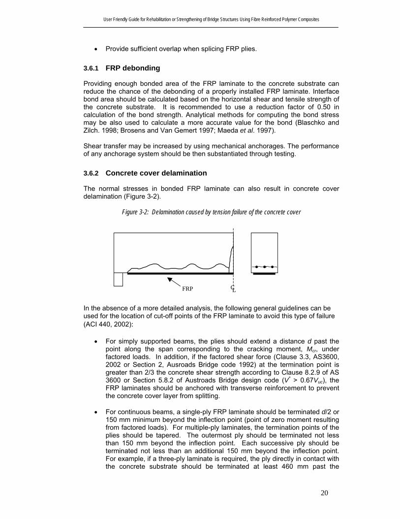
3.6.2 Concrete cover delamination
The normal stresses in bonded FRP laminate can also result in concrete cover delamination (Figure 3-2).
Figure 3-2: Delamination caused by tension failure of the concrete cover
LC
FRP In the absence of a more detailed analysis, the following general guidelines can be used for the location of cut-off points of the FRP laminate to avoid this type of failure (ACI 440, 2002):
• For simply supported beams, the plies should extend a distance d past the point along the span corresponding to the cracking moment, Mcr, under factored loads. In addition, if the factored shear force (Clause 3.3, AS3600, 2002 or Section 2, Ausroads Bridge code 1992) at the termination point is greater than 2/3 the concrete shear strength according to Clause 8.2.9 of AS 3600 or Section 5.8.2 of Austroads Bridge design code (V* > 0.67Vuc), the FRP laminates should be anchored with transverse reinforcement to prevent the concrete cover layer from splitting.
• For continuous beams, a single-ply FRP laminate should be terminated d/2 or
150 mm minimum beyond the inflection point (point of zero moment resulting from factored loads). For multiple-ply laminates, the termination points of the plies should be tapered. The outermost ply should be terminated not less than 150 mm beyond the inflection point. Each successive ply should be terminated not less than an additional 150 mm beyond the inflection point. For example, if a three-ply laminate is required, the ply directly in contact with the concrete substrate should be terminated at least 460 mm past the

User Friendly Guide for Rehabilitation or Strengthening of Bridge Structures Using Fibre Reinforced Polymer Composites
21
inflection point (Figure 3-3). These guidelines apply for positive and negative moment regions.
Figure 3-3 : Graphical representation of the guidelines for allowable termination points of a three-ply FRP laminate.
150 150 df l ≥
M = M u
(a) Simply Supported Beam
M = M cr
M = 0
(b) Continuous Beam
M = M u
150150
150 df l≥
Point of inflection
150
3.7 Detailing of laps and splices
FRP laminates can be spliced only as permitted on drawings or in specifications or as calculated for load transfer following the recommendations of the system manufacturer. The fibres of FRP systems should be continuous and oriented in the direction of the design tensile forces. Fibre continuity can be maintained with a lap splice by overlapping the fibres along their length. The required overlap should be calculated based on the tensile strength and thickness of the FRP material system and on the bond strength between adjacent layers of FRP laminates. Sufficient overlap should be provided to promote the failure of the FRP laminate before debonding of the overlapped FRP laminates. Appropriate development length/area at splices, joints, and termination points should be provided for a Jacket-type FRP systems used for column members. This is to ensure that the failure will be through the FRP jacket thickness rather than failure of the spliced sections.

User Friendly Guide for Rehabilitation or Strengthening of Bridge Structures Using Fibre Reinforced Polymer Composites
22
3.8 Summary of Strengthening Techniques Table 3-2 presents summary of strengthening techniques. The type of FRP, design actions and special need of each technique are also tabulated.
Table 3-2: Summary of strengthening techniques
Strengthening Method Design Action Type of FRP
Special Considerations
Wet lay up of FRP sheets to the tension zone of the soffit of
a beam or slab
Flexural strengthening
Sheets or strips De-bonding
Attaching prefabricated FRP sheets to the tension zone of the soffit of a beam or slab
Flexural strengthening
Sheets or strips De-bonding
The different types of wrapping schemes to increase the shear strength of a beam or column
Shear strengthening Sheets Direction of
fibres
Automated winding of wet fibers under a slight angle around columns or other
structures,
Shear and axial compression strengthening
Sheets Equipment availability
Attaching prestressed FRP strips to the tension zone of the soffit of a beam or slab
Flexural strengthening Strips Anchorage
Fusion-bonded pin-loaded straps
Flexural and shear strengthening
Pin-loaded straps
Equipment availability
In-situ fast curing using heating device
Flexural strengthening Strips -
Prefabricated U or L shape strips for shear strengthening
Shear strengthening Strips Direction of
fibres Bonding FRP strips inside
concrete slits Flexural
strengthening Strips Crack initiation
FRP impregnation by vacuum to the tension zone of the soffit
of a beam or slab
Flexural Strengthening Strips Equipment
availability
Prefabricated FRP shells or jackets for the confinement of
circular or rectangular columns
Axial compression strengthening and
ductility enhancement
Sheets
Confining pressure will be different to that
of steel
FRP wrapping for axial compression strengthening and ductility enhancement
Axial compression strengthening and
ductility enhancement
Sheets Confining
pressure will be different
FRP wrapping for torsional strengthening
Torsional strengthening Sheets Direction of
fibres

User Friendly Guide for Rehabilitation or Strengthening of Bridge Structures Using Fibre Reinforced Polymer Composites
23
4 GENERAL DESIGN CONSIDERATIONS The successful structural repair and upgrading involves four basic elements: concepts used in system design; compatibility and composite behaviour of existing members with upgraded system; field application methods; and most importantly, design details. The status of the structure to be strengthened should be investigated and repairs should be performed as appropriate. It is of great importance to select the best FRP system for a particular rehabilitation need. Proper designing, detailing and applying it in a particular structure should guarantee the overall structural behaviour and safety of the strengthened member.
4.1 Design Philosophy In common with most codes of practice for structural design, the design methods contained in this report are based on limit-state philosophy. This ensures that a strengthened member will not reach a limit state during its design life. All necessary design situations and load combinations should be considered. In assessing the effect of a particular limit state on the structure, the designer will need to assume certain values for the design loading and the design strength of the materials. This method ensures safety levels in serviceability limit state (deflection, cracking) and ultimate limit state (failure, rupture, fatigue). The possible failure modes, stresses and strains resulting from this method in each material should be assessed in order to find the nominal strength of a member. The design of a FRP strengthening system should include the effects of FRP composites, force transfer through bond interface, detailing rules and special provisions. Design calculations are based on analytical or (semi-) empirical models. A thorough field inspection, review of existing design and a structural analysis should be performed for the structure to be strengthened by FRP. Depending on that investigation, proper repair should be undertaken as the application of FRP is not meant to confine defects such as steel corrosion. Redistribution of moments is not normally allowed in FRP as it lacks plasticity. In strengthening columns and walls using FRP composites, it is necessary to consider the out-of plane deformations (second order effects). Verification of both the serviceability limit state (SLS) and the ultimate limit state (ULS) should be performed in the design procedure. As shown in FIB Bulletin 14 (2002), the following situations may be considered:
• Persistent situation, corresponding to the normal use of the structure; • Accidental situation, corresponding to debonding or delamination of the FRP
system (due to e.g. impact, vandalism, fire); and • Special design considerations (e.g. bond stresses due to differences in
coefficient of thermal expansion, fire resistance, impact resistance).
User Friendly Guide for Rehabilitation or Strengthening of Bridge Structures Using Fibre Reinforced Polymer Composites
24
4.1.1 Verification of the serviceability limit state
The serviceability of a strengthened member (deflections, crack widths) under service loads should satisfy acceptable provisions of AS 3600, 2002 and Austroads Bridge design code. To meet this requirement, the serviceability limit state verification normally should consider:
• Stress limits (prevent steel yielding, damage or excessive creep of concrete and excessive creep or creep rupture of the FRP);
• Acceptable deformations or deflections; and • Cracking (including interface bond cracking).
If the aim of applying a strengthening procedure is to improve the serviceability, then the serviceability limit state will govern the design, rather than the ultimate limit state.
4.1.2 Verification of the ultimate limit state
The strength of strengthened member depends on the controlling failure mode. All possible failure modes should be investigated for an FRP strengthened section (Ganga Rao and Vijay 1998). In general, the failure modes can be subdivided to those assuming full composite action between the reinforced concrete / prestressed concrete member and the FRP and those verifying the different debonding mechanisms that may occur. Load combinations and partial safety factors should be applied as specified in relevant code and standards.
4.1.3 Accidental situation
The level of strengthening that can be achieved through the use of externally bonded FRP reinforcement is often limited by considerations of the accidental design situation as required by design codes. The structure should be checked for loss of the FRP strengthening due to an accidental situation e.g. impact, vandalism or fire. The un-strengthened member is then subjected to all relevant accidental load combinations. This may be verified in the ultimate limit state, considering the partial safety factors for the materials and considering reduced partial safety coefficients and combination factors for the loads, as provided in relevant codes and standards.
4.1.4 Special design considerations
Environmental conditions uniquely affect resins and fibres of various FRP systems. Special design considerations such as cyclic loading, extra bond stresses due to the difference in thermal expansion between FRP and concrete, impact and fire resistance may also be relevant. The material properties used in design should account for the degradation and effect of impact and fire. However, it is important that sufficient attention is paid to the special design aspects, as they can have a considerable influence on the structural safety.

User Friendly Guide for Rehabilitation or Strengthening of Bridge Structures Using Fibre Reinforced Polymer Composites
25
4.1.5 Durability
Many FRP systems exhibit reduced mechanical properties after exposure to certain environmental factors, including temperature, humidity, and chemical exposure. Hence the environmental conditions must be taken into account from the start of the design process. The exposed environment, duration of exposure, resin type and formulation, fibre type, and resin-curing methods are some of the factors that influence the extent of the reduction in mechanical properties. These factors and their influences with respect to the durability should be considered and, if needed, protective measures can be taken.
4.2 Safety Concept and Strengthening Limits The FRP strengthening system should be designed to provide sufficient structural safety, including sufficient ductility. A major task involved in design is the choice of the appropriate margin of safety for the different limit states together with corresponding value for the associated safety coefficient.
4.2.1 Safety concept with respect to the ultimate limit state
In limit state design, the variability of material properties is taken into account by assuming a characteristic strength. Characteristic strength usually is taken as the value below which not more than 5% of test results lie. A similar approach is used to define characteristic strength of FRP, but the acceptable failure rate may be reduced to 1%. The modelling of the strengthened member should consider the different failure modes that may occur. Using FRP materials with no yielding capacity and, considering concrete substrate with unfavourable post-failure in tension leads to a brittle failure. Therefore, the brittle failure modes, such as shear and torsion, should be prevented in design of an FRP system. For the same reason, it should be guaranteed that the internal steel is sufficiently yielding in Ultimate Limit State, so that the strengthened member will fail in a ductile manner. In order to discuss the failure of the strengthened member, strain distribution at Ultimate Limit State in a critical section can be considered as shown in Figure 4-1 (FIB Bulletin 14, 2002).
Figure 4-1: Strain distribution at Ultimate Limit State in the critical section of strengthened flexural members
0ε
fεmin,fεfucfu εε ≤,
fuε
suε ydε
cuε
x
h
d
AB

User Friendly Guide for Rehabilitation or Strengthening of Bridge Structures Using Fibre Reinforced Polymer Composites
26
εo is the initial strain at the extreme tensile fibre before strengthening, εf,min is the minimum allowable FRP strain at ultimate and εfu,c is the FRP strain in the critical section at ultimate. Strengthening is not always a primary goal of the application of externally bonded reinforcement. For example, in columns, FRP wrapping is used to improve ductility as well as load carrying capacity by activating multiaxial stresses or by counteracting lateral tensile stresses and shear forces. This technique favourably influences the structural safety as confinement results in increased ductility.
4.2.2 Strengthening limits
There should be strengthening limits to protect the strengthened structure against collapse due to bond failure or other failure of FRP system caused by fire, vandalism or other causes. ACI Committee 440 (2002) suggested a careful consideration to determine reasonable strengthening limits. It has been recommended by some designers and system manufacturers that even the unstrengthened structural member should have sufficient strength to resist a certain level of load so that in case the FRP system is damaged the structure is still capable of resisting certain loads without collapse. ACI Committee 440 (2002) recommended that the existing strength of the structure should be sufficient to resist a level of load as described by Eq. (4-1).
( ) ( )newLLDLexistingn S85.0S2.1R +≥φ 4-1
4.3 Ductility The use of externally bonded FRP reinforcement for flexural strengthening will reduce the ductility of the original member. In some cases, the loss of ductility is negligible. Sections that experience a significant loss in ductility, however, should be addressed. To maintain a sufficient degree of ductility, the strain level in the steel at the ultimate-limit state should be checked.
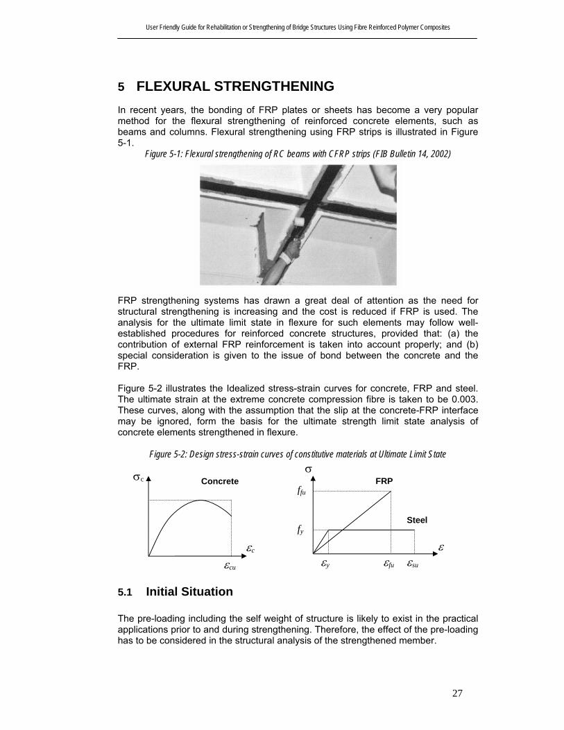
User Friendly Guide for Rehabilitation or Strengthening of Bridge Structures Using Fibre Reinforced Polymer Composites
27
5 FLEXURAL STRENGTHENING In recent years, the bonding of FRP plates or sheets has become a very popular method for the flexural strengthening of reinforced concrete elements, such as beams and columns. Flexural strengthening using FRP strips is illustrated in Figure 5-1.
Figure 5-1: Flexural strengthening of RC beams with CFRP strips (FIB Bulletin 14, 2002)
FRP strengthening systems has drawn a great deal of attention as the need for structural strengthening is increasing and the cost is reduced if FRP is used. The analysis for the ultimate limit state in flexure for such elements may follow well-established procedures for reinforced concrete structures, provided that: (a) the contribution of external FRP reinforcement is taken into account properly; and (b) special consideration is given to the issue of bond between the concrete and the FRP. Figure 5-2 illustrates the Idealized stress-strain curves for concrete, FRP and steel. The ultimate strain at the extreme concrete compression fibre is taken to be 0.003. These curves, along with the assumption that the slip at the concrete-FRP interface may be ignored, form the basis for the ultimate strength limit state analysis of concrete elements strengthened in flexure.
Figure 5-2: Design stress-strain curves of constitutive materials at Ultimate Limit State
5.1 Initial Situation The pre-loading including the self weight of structure is likely to exist in the practical applications prior to and during strengthening. Therefore, the effect of the pre-loading has to be considered in the structural analysis of the strengthened member.
Concrete
εc
εcu
σc
ε
εfu
σ
εsu
fy
ffu
εy
FRP
Steel

User Friendly Guide for Rehabilitation or Strengthening of Bridge Structures Using Fibre Reinforced Polymer Composites
28
The effect of pre-loading due to self-weight and service loads is generally beneficial if the beam fails by FRP rupture, but this effect is generally insignificant. The effect of pre-loading is more significant and detrimental if the beam fails by concrete crushing and should be investigated in design calculations. As the service moment, Mo is typically larger than the cracking moment, Mcr, therefore, the calculation will be based on a cracked section.
5.2 Design Assumptions For a section strengthened with an externally bonded FRP system, the following assumptions are made in calculating the flexural strength (ACI Committee 440, 2002).
• Design calculations are based on the actual dimensions of the existing member to be strengthened, its configuration of reinforcing steel, and its material properties;
• The strains in the reinforcement and concrete are directly proportional to the distance from the neutral axis, that is, plane sections remain plane after loading;
• There is no relative slip between external FRP reinforcement and the concrete;
• The shear deformation within the adhesive layer is neglected since the adhesive layer is very thin with slight variations in its thickness;
• The maximum usable compressive strain in the concrete is 0.003; • Concrete resists no tension; and • The FRP reinforcement has a linear elastic stress-strain relationship until
failure.
5.3 Design for Strength The strengthened structure and its component members should be designed for the strength as described in following subsections.
5.3.1 Section shear strength
When the flexural strength of a RC section is increased using FRP reinforcement, it is important to check that the member will be capable of resisting the shear forces associated with the increased flexural strength.
5.3.2 Existing substrate strain
The strains due to pre-loading including the self-weight of structure and any prestressing forces should be considered as initial strains in design of the strengthened member. The initial strain level on the bonded substrate, εo, can be determined from an elastic analysis of the existing member, considering all loads that will be on the member, during the installation of the FRP system. It is recommended that the elastic analysis of the existing member be based on cracked section properties.

User Friendly Guide for Rehabilitation or Strengthening of Bridge Structures Using Fibre Reinforced Polymer Composites
29
5.4 Nominal strength The strength-design approach requires that the design strength in bending of a member is not less than the design action effect as indicated by Eq. 5-1. Design flexural strength, φMuo, refers to the nominal strength of the member multiplied by a strength-reduction factor (see Clause 8.4.1 of AS 3600 or Section 5.8.1 of Austroads Bridge design code), and the required moment strength, M*, refers to the load effects calculated from factored loads (see Clause 3.3 of AS 3600 or Section 2 of Austroads Bridge design code). This guide recommends calculation of required moment strength of a section using factored loads as required by Austroads Bridge design code (1992) or AS 3600 (2002). This guide also recommends the use of an additional strength reduction factor of 0.85 applied to the flexural contribution of the FRP reinforcement alone, ψ f = 0.85 (ACI 440, 2002) with the strength reduction factors (φ) required by AS3600 (2002). This additional reduction factor is meant to account for lower reliability of the FRP reinforcement.
φMuo ≥ M * 5-1 The nominal flexural strength of an FRP-strengthened concrete member can be determined based on the section analysis using strain compatibility and internal force equilibrium based on AS 3600 or Austroads Bridge design code.
Figure 5-3: Internal strain and stress distribution for rectangular section under bending moment at ultimate state
Stress DistributionStrain DistributionReinforced Concrete Section
A = n t wf f f f fffff = E ε
f = E εs s s sf
0.85 f ' c
γ x
ε s
cuε
ofε ε
d-x
h-x
d
h
uk d
= x
Neutral Axis
The nominal flexural strength of the section can then be calculated from Eq. 5-2.
⎥⎦
⎤⎢⎣
⎡⎟⎠
⎞⎜⎝
⎛ −+⎟⎠
⎞⎜⎝
⎛ −=22
8.0dk
hEAdk
dfAM uffff
ussuo
γεψ
γφ
5-2
5.4.1 Failure modes
The failure modes observed in experimental studies reported in the literature, can be classified into seven main categories as follows.
• flexural failure by FRP rupture; • flexural failure by crushing of compressive concrete;

User Friendly Guide for Rehabilitation or Strengthening of Bridge Structures Using Fibre Reinforced Polymer Composites
30
• shear failure; • concrete cover separation; • plate-end interfacial de-bonding; • intermediate flexural crack-induced interfacial de-bonding; and • intermediate shear crack-induced interfacial de-bonding.
All these failure modes can be divided into two categories; (1) Full composite action of concrete and FRP is maintained until the concrete reaches crushing in compression or the FRP fails in tension (such failure modes may also be characterized as “classical”) and; (2) Loss of composite action between concrete and FRP prior to failure (e.g. due to de-bonding or peeling-off of the FRP). The flexural strength of a strengthened section depends on the controlling failure mode. Concrete crushing is assumed to occur at the ultimate compressive strain of (εc = εcu = 0.003) and rupture of the FRP laminate is assumed to occur at the ultimate tensile strain of (εf = εfu). In order to prevent de-lamination of the FRP reinforcement, this guide recommends limiting the strain level developed in the laminate. Eq. (5-3) gives an expression for a bond dependent coefficient, κm, (ACI 440, 2002).
⎪⎪
⎩
⎪⎪
⎨
⎧
>≤⎟⎟⎠
⎞⎜⎜⎝
⎛
ε
≤≤⎟⎟⎠
⎞⎜⎜⎝
⎛−
ε=κ
000,180tnEfor90.0tnE
000,9060
1
000,180tnEfor90.0000,360tEn
160
1
fffffu
ffff
fum 5-3
The strain level in the FRP laminate may be limited by multiplying the rupture strain of FRP by the factor κm, to prevent debonding. The number of plies, n, used in this equation is the number of plies of FRP flexural reinforcement at the location along the length of the member where the moment strength is being computed.
5.4.2 Strain level in the FRP Reinforcement
The strain level in FRP laminate at the ultimate –limit state due to maximum factored loads should be less than the limiting strain, which is illustrated in Eq. (5-4)
fumou
ucuf dk
dkhεκεεε ≤−⎟⎟
⎠
⎞⎜⎜⎝
⎛ −= 5-4
Where, εo is the initial substrate strain as described Section 4.1.
5.4.3 Stress level in the FRP reinforcement
The effective stress level in the FRP reinforcement can be calculated based on maximum effective strain, assuming perfectly elastic behaviour.
fff Ef ε= 5-5
5.5 Creep-rupture and fatigue stress limits
The stress level in the FRP laminate should be checked to avoid creep-rupture of the FRP reinforcement under sustained stresses or failure of the FRP due to cyclic stresses and fatigue. An elastic analysis can be used as these stress levels will be within the elastic response range of the member. The creep-rupture phenomenon

User Friendly Guide for Rehabilitation or Strengthening of Bridge Structures Using Fibre Reinforced Polymer Composites
31
and fatigue characteristics of FRP material were described in Section 2.6 and the resistance of the various types of fibres was examined. The stress limits should be imposed to prevent failure of an FRP-reinforced member due to creep-rupture and fatigue of the FRP. An elastic analysis can be used to determine the stress level in the FRP reinforcement considering an applied moment due to all sustained loads (dead loads and the sustained portion of the live load) plus the maximum moment induced in a fatigue loading cycle. Eq. (5-6) may be used limiting the stress limits with a reasonable margin of safety. Values for safe sustained plus cyclic stress levels are given in Table 5-1. These values are based on the stress limits previously stated in Section 2.6 with an imposed safety factor of 1/0.60.
Sustained plus cyclic stress limit ≥ ff,s 5-6
Table 5-1: Sustained plus cyclic service load stress limits in FRP reinforcement Fibre Type
Stress Type Glass FRP Aramid FRP Carbon FRP
Sustained plus cyclic stress limit 0.20 ffu 0.30 ffu 0.55 ffu
5.6 Serviceability The strengthened member should satisfy the provisions of AS 3600 (2002) of the serviceability of a member (deflections, crack widths) under service loads. The transformed section analysis may be used to assess the effect of the FRP external reinforcement on the serviceability. The transformed area of FRP can be computed by multiplying the area of FRP by the modular ratio of FRP to concrete. The distribution of strain and stress in the reinforced concrete section is shown in Figure 5-4.
Figure 5-4: Elastic strain and stress distribution
Neutral Axis
k d
h
d
h-k
d
d(1-
k)
εε f,s o
εc
s,sε s,sss,sf = E ε
f = E εf,s f f,sfffA = n t w
Reinforced Concrete Section Strain Distribution Stress Distribution
kd/3
cccf = E ε
Similar to the conventional method, the depth to the neutral axis at service, kd, can be computed by taking the first moment of area of the transformed section. The difference in the initial strain level of FRP may be ignored as it does not greatly influence the depth of the neutral axis in the elastic analysis.

User Friendly Guide for Rehabilitation or Strengthening of Bridge Structures Using Fibre Reinforced Polymer Composites
32
The yielding of the existing internal steel reinforcement under service loads should be prevented to avoid inelastic deformations of the reinforced concrete members strengthened with external FRP reinforcement. The limitation of 80 % of the yield strength may be the applied, see Eq. (5-7).
yss ff 80.0, ≤ 5-7
The stress in the FRP may be computed using Eq. 5-8 with ssf , from Eq. 5-7 and applied bending moment under serviceability load combinations based on Austroads Bridge design code provisions.
fos
fsssf E
kddkdh
EE
ff ε−−−
⎟⎟⎠
⎞⎜⎜⎝
⎛= ,, 5-8
The stress in the FRP under service loads, sff , should be checked with the limits
described in Table 5-1.
5.7 Anchorage Experimental investigations show that the FRP rupture is a rare event and delamination of FRP strips is more likely occur before stress in the FRP reach the ultimate level. Debonding implies the complete loss of composite action between the concrete and FRP laminates. Bond failure will be a brittle failure and should be prevented at any cost. This guide recommends checking the following failure modes to prevent de-lamination of FRP, depending on the starting point of the de-bonding process. (FIB, 2002)
• De-bonding in an un-cracked anchorage zone; • De-bonding caused at flexural cracks; and • De-bonding caused at shear cracks.
Approach 1: Verification of end anchorage, strain limitation in the FRP, This approach involves two independent steps: first, the end anchorage should be verified based on the shear stress-slip constitutive law at the FRP-concrete interface. Then strain limitation should be applied on the FRP to ensure that bond failure far from the anchorage is prevented. In the following the model of Holzenkamper (1994) as modified by Neubauer and Rostasy (1997) is presented
ctmffbcfa ftEbkkcN 1max, α= (N) 5-9
ctm
ffb fc
tE
2max, =l (mm) 5-10
where α is a reduction factor, approximately equal to 0.9, to account for the influence of inclined cracks on the bond strength (Neubauer and Rostásy 1999) (note that α =1 in beams with sufficient internal and external shear reinforcement and in slabs); kc is a factor accounting for the state of compaction of concrete (kc can generally be assumed to be equal to 1.0, but for FRP bonded to concrete faces with low

User Friendly Guide for Rehabilitation or Strengthening of Bridge Structures Using Fibre Reinforced Polymer Composites
33
lb
Ns1
Nf
srm As1
Envelope line of the tensile force
Envelope line of the resisting tensile force
compaction, e.g. faces not in contact with the formwork during casting, kc = 0.67) and kb is a geometry factor:
1
4001
206.1 <
+
−=
f
f
b bb
b
k 5-11
with bf/b ≥ 0.33. Note that b, bf and tf are measured in mm, and Ef and fctm are in MPa. c1 and c2 in Eqs. 5-7 and 5-8 may be obtained through calibration with test results; for CFRP strips they are equal to 0.64 and 2, respectively. For bond lengths max,bb ll < , the ultimate bond force was calculated according to Holzenkämpfer (1994) as follows:
⎟⎟⎠
⎞⎜⎜⎝
⎛−=
max,max,max, 2
b
b
b
bfafa NN
l
l
l
l 5-12
Theoretical cut off point then can be determined as follows
cs
fffa I
xhAMN
)(max,
−=
α 5-13
Provided anchorage length > max,bl 5-14 Approach2: Calculation of the envelope line of tensile stress A more detailed approach to prevent peeling-off at flexural cracks in case of short-term static loading is proposed by Niedermeier (2000). The aim of this approach is to calculate the maximum possible increase in tensile stress within the FRP strips, which can be transferred by means of bond stresses between two subsequent flexural cracks. This increase should be compared to the increase according to the design assumption of the full composite action.
Figure 5-5: Envelope line of the tensile forces
The basic approach consists of three steps

User Friendly Guide for Rehabilitation or Strengthening of Bridge Structures Using Fibre Reinforced Polymer Composites
34
• Determination of the most unfavourable spacing of flexural cracks; • Determination of the tensile force within FRP strip between two subsequent
cracks according to the design in bending; and • Determination of the maximum possible increase in tensile stress in the FRP.
The crack spacing between two subsequent cracks can be assumed to be 1 to 2 times of the transmission length tl , with assumption of a constant mean bond stresses of both the internal and external reinforcement. The mean bond stress of the internal and external reinforcements can be then determined using Eqs 5-13 and 5-14 respectively. The transmission length and crack spacing may be calculated with Eqs 5-15 and 5-16.
ctmsm f85.1=τ 5-15
ctmfm f44.0=τ 5-16
( )∑ ∑+==
πττ ssmfsmm
crtrm dbz
Ms 122l 5-17
)()(
85.01
1
ssff
ssffm EAEA
EdAEhAz
+
+= 5-18
The tensile stress in the FRP laminate at each crack then can be calculated taking into account strain compatibility and internal force equilibrium. The maximum tensile force, which can be transferred from FRP to the concrete by means of bond stresses at the anchorage zone, can be estimated using Eqs 5-17 and 5-18
Figure 5-6: End anchorage in an un-cracked concrete zone (FIB 2002)
f
ctmckf
cfad t
ffEcγ
σ 3max, = (MPa) 5-19
ctmck
ffb ff
tEc4max, =l (mm) 5-20
where 3c and 4c can be obtained from the selected fracture model. In absence of the test data it can be taken as 0.23 and 1.44 respectively. Please note that an increase

User Friendly Guide for Rehabilitation or Strengthening of Bridge Structures Using Fibre Reinforced Polymer Composites
35
in anchorage length above max,bl may not result in an increase in resisting tensile stresses due to the limitation of fracture energy. The maximum tensile stress for anchorage length lower than max,bl can be estimated by Eq. 5-18.
max,max,max,
2 fadb
b
b
bfad σσ ⎟
⎟⎠
⎞⎜⎜⎝
⎛−=l
l
l
l 5-21
A simplified bilinear stress-slip relation can be used for analysis of the bond behavior of the FRP laminate. The method is illustrated in Figure 5-7 and Figure 5-8.
Figure 5-7: Element between two subsequent cracks (FIB 2002)
Figure 5-8: Diagram of the maximum possible increase in tensile stress between two subsequent cracks (FIB 2002)
The points A, B and C shown in the diagram may be estimated using the following equations. The point A corresponds to the verification at the end anchorage where
fdσ = 0. The matching maximum increase in stress or in this case, the maximum

User Friendly Guide for Rehabilitation or Strengthening of Bridge Structures Using Fibre Reinforced Polymer Composites
36
anchorable tensile stresses, max )( A
fdσ∆ ,)(B
fσ can be estimated from equations 5-
17 and 5-19 and the related maximum increase )(B
fdσ∆ can be estimated from following equations.
f
rmctmck
rm
fBf t
sffc
sEc
465)( −=σ (MPa) 5-22
( )⎟⎟⎟
⎠
⎞
⎜⎜⎜
⎝
⎛−+= )(2)(
23)( 1 B
fB
ff
ctmckf
c
Bfd t
ffEcσσ
γσ (MPa) 5-23
where 5c and 6c can be assumed as 0.185 and 0.285 respectively. The linear increase between points A and B and B and C can then be estimated by Eq. 5-22 and 5-23 respectively.
( )fdB
f
Bfd
AfdA
fdfd σσ
σσσσ )(
)()()()1( maxmax
maxmax∆−∆
−∆=∆ 5-24
⎟⎟⎟
⎠
⎞
⎜⎜⎜
⎝
⎛−+=∆ fdfd
f
ctmckf
cfd t
ffEcσσ
γσ 2
23)2( 1max 5-25
For high tensile stresses, the upper limit of the increase in stresses may be determined by following equation.
fdfdfd f σσ −=∆ )3(max 5-26
Approach 3: Verification of anchorage and the force transfer between FRP and concrete If verification of the end anchorage has already been performed, it should be then verified that the resulted shear stress τb from the change of tensile force along the FRP at the FRP-concrete interface is limited.
c
ctkcbd
ff
γ8.1= 5-27
yds εε <1 : cbd
ff
ssf
d f
EAEA
db
V<
⎟⎟⎠
⎞⎜⎜⎝
⎛+ 1195.0
5-28
yds εε ≥1 : cbd
ffs
d fb
zzV
>+
2
5-29
5.8 Special Cases
5.8.1 Pre-tensioned or post-tensioned concrete elements
FRP strengthening of pre-stressed elements has been addressed only in few studies both experimentally and theoretically. From the FRP strengthened bridges so far,

User Friendly Guide for Rehabilitation or Strengthening of Bridge Structures Using Fibre Reinforced Polymer Composites
37
only 10% are pre-stressed (FIB Bulletin 14, 2002). Therefore, FRP-strengthening of pre-stressed elements needs careful attention. The following sections cover the FRP strengthening of bridge superstructures (girders, beams and decks) and slabs for prefabricated floors. Strengthening of elements with either un-bonded tendons, external tendons, or made from lightweight aggregate concrete is not covered here.
5.8.1.1 FRP strengthening of pre-stressed concrete members Strengthening of a pre-stressed member usually takes place after all long term phenomena (creep, shrinkage, relaxation) have fully developed. As a result, the assessment of the existing pre-stressed structure before FRP strengthening has become more complicated. Therefore conceptual implications of the long term phenomena should be clearly understood and careful attention should be paid in designing a FRP strengthening of a pre-stressed member. As shown in the FIB Bulletin 14 (2002), construction sequence, pre-stressing phases, correct description of long-term phenomena along with their superposition and mutual interaction, and evaluation of damage effects (due to impact, etc.) on the section stress pattern should be carefully analysed in the assessment of the existing pre-stressed structure. Assessment itself should be in accordance with the national standards. All time dependent effects can be considered as a one single reduction coefficient and pre-strengthening stress/strain behaviour can be computed. The effects of such simplifications in economical and safety aspects should be studied. However, these kinds of simplifications should be avoided where more detailed preliminary assessment is needed.
5.8.1.2 Safety considerations The conventional procedures for pre-stressed concrete (in accordance with relevant national codes) can be applied to the design of the FRP strengthening system once the existing stress state of the pre-stressed member is assessed. FRP contribution can then be included in the same form as adopted for reinforced concrete. The FRP-strengthened member should be checked for cracking criteria according to the serviceability limit state. Moreover, verifications should be made for the stress limits for steel and concrete given by the national codes. A controversial issue exists in the strengthening design philosophy about the presence of tensile stresses in the pre-stressed concrete section after it is strengthened by FRP. This requires careful consideration. Determining the initial strain in the pre-stressed element where FRP application is to be made, is another important part in the design procedure. The actual FRP strain will be computed by subtracting the initial strain from the strain obtained from the plane section assumption. This is needed to be considered in the ultimate limit state, as FRP rupture is the governing event leading to collapse. Therefore it should be calculated to the maximum accuracy.
5.8.1.3 Modelling issues Fibre section models can be used to verify the effectiveness of the design procedures because all long term phenomena can be included in the material level and finally integrated over the section analysis. The finite element analysis can be used to obtain the global analysis of the strengthened member. The numerical method needs to have all the issues discussed above.

User Friendly Guide for Rehabilitation or Strengthening of Bridge Structures Using Fibre Reinforced Polymer Composites
38
5.8.2 Strengthening with pre-stressed FRP
5.8.2.1 Design The cracking and yield loads of a beam can be determined using conventional reinforced concrete theory provided that the initial stress in the strips for strengthening is included in the calculations. However, premature failure through other modes must be examined. As the flexural ultimate load is approached, cracking of the concrete will inevitably occur and the section will revert to normal reinforced concrete behaviour. In this case the ultimate shear strength of a beam strengthened with a stressed strip will be the same as that of the original beam. The contribution of the strip to dowel action must be ignored in calculating the shear resistance, unlike the main tensile steel reinforcement that can be included. The reason for this is that any vertical movement may lead to peeling-off failure resulting in de-bonding of the strip from the concrete. The strip would need to be enclosed by the shear links to increase the effectiveness. The ultimate flexural strength of a beam with a stressed strip will be similar to that of a beam with an unstressed strip. However, the initial strain in the strip will be added to that induced by bending so that strip failure is more likely and the failure mode of “steel yielding followed by FRP fracture” may be activated.
5.8.2.2 Pre-stress losses Losses in prestress as shown below should be considered in design procedures.
• Relaxation of the steel tendons; • Immediate elastic deformation of the concrete; • Creep and shrinkage of the concrete under compressive pre-stress over the
service life of the structure; • Slippage of the tendons at their ends that occurs when the pre-stress is
transferred into the anchorages; and • Friction between the strip and the concrete if the strip does touch the
concrete.
5.8.2.3 FRP end anchorage Experimental studies have shown that only about 6% of the ultimate strength of the FRP strip can be transferred into the concrete by the adhesive alone (e.g. Triantafillou et al. 1992, Deuring, 1993). Therefore a suitable anchorage system is necessary to transfer a great pre-stressing force (50% of the ultimate strength of the strip) and to avoid peeling off the end. The value of 50% of the ultimate strength of the strip should not be exceeded. Where the tests are based on the ultimate strength of coupon specimens this value should not exceed 33%. Developed FRP end anchorage systems must be investigated with appropriate tests.

User Friendly Guide for Rehabilitation or Strengthening of Bridge Structures Using Fibre Reinforced Polymer Composites
39
6 STRENGTHENING IN SHEAR AND TORSION Flexural and shear failure are the two main failure modes for normal RC beams. Flexural failure is generally preferred to shear failure, as the strength-governing failure mode, because the former is ductile, whilst the latter is brittle. A ductile failure allows stress re-distribution and provides warning to users, whilst the brittle failure is sudden and thus catastrophic. When a RC beam is deficient in shear or when its shear capacity is less than the flexural capacity after flexural strengthening, shear strengthening must be considered. The shear strength of existing concrete beams and columns can be increased by fully or partially wrapping the members using FRP systems (Malvar et al. 1995; Chajes et al. 1995; Norris et al. 1997; Kachlakev and McCurry 2000). Providing additional shear strength is effective if the fibre orientation is transverse to the axis of the member or perpendicular to potential shear (Sato et al. 1996). Increased shear strength of the FRP strengthened member can result in flexural failure which is desirable compared to shear failure. Apart from the common advantages of corrosion resistance and high strength-to-weight ratio of FRPs, the versatility of FRPs in coping with different sectional shapes and corners is also a benefit for shear strengthening applications. Furthermore, shear strengthening can be provided at locations of possible plastic hinges, stress reversals and where post yield flexural behavior of members in moment frames needs to be enhanced.
6.1 General Design Considerations A number of failure modes have been observed in experiments of RC beams strengthened for shear with bonded FRPS. These include shear failure with FRP rupture, shear failure without FRP rupture, shear failure due to de-bonding and local failure. However, detailed analyses of shear strengthening of RC members have been relatively sparse. Most researchers have idealized the shear strengthening of RC members using FRP composites with those using internal steel stirrups. RC beams strengthened in shear using externally bonded FRPs show complex behaviour. Both the shear strength and the failure mode are influenced by many factors such as the size and geometry of the beam, the strength of the concrete internal shear and flexural reinforcement, loading conditions, the method of strengthening, and the properties of the bonded FRP. However all existing models use the following expression to calculate the shear strength of a strengthened member, Vu :
ufusucu VVVV ++= 6-1
where Vuc is the shear capacity of the concrete, which consist of shear contribution of concrete in compression, aggregate interlock and dowel action of steel flexural reinforcement, Vus is the contribution of the steel stirrups and bent up bars and Vuf is the contribution of FRP. Vuc and Vus may be calculated according to Clause 8.2 of AS 3600 or Section 5.8.2 of Austroad Bridge design code, so the main differences between available models lie in the evaluation of the FRP contribution. Triantafillou (1998) and Triantafillou and Antonopoulos (2000) argued that to predict accurately the contribution of FRP to shear resistance is impossible, because it depends on the failure mechanism which in turn depends on various factors. They

User Friendly Guide for Rehabilitation or Strengthening of Bridge Structures Using Fibre Reinforced Polymer Composites
40
used a semi-quantitative approach. It has been shown that just before concrete fails in shear, the externally bonded FRP strips stretched in the principal fibre direction up to a strain level known as effective strain εf,e. This effective strain is normally less than the tensile fracture strain of FRP composites, εu. Effective strain multiplied by the elastic modulus of FRP in the principal fibre direction, Ef and the FRP cross sectional area will ultimately give the total force carried by FRP at the shear failure of the member. The effective FRP strain is extremely difficult to estimate. However, a detailed analysis of experimental data will help in estimating this. It should be noted that failure is assumed to be always defined by concrete diagonal tension splitting. The failure may occur either prematurely, as a result of FRP debonding, or after the FRP has been stretched considerably as illustrated in Figure 6-1. In the latter case the FRP may fracture either exactly at the peak load or a little after, due to overstressing in the vicinity of the diagonal cracks.
Figure 6-1: Schematic illustration of shear failure response
Load
Displacement
Shear fractureand peeling-off
Shear fracture andFRP fracture Shear fracture
FRP fracture
The chief disadvantage of this model is that no distinction is made between the different strengthening schemes or failure modes. It may be also argued that at the ultimate limit state a certain degree of FRP debonding at the concrete-FRP interface is always expected, even if the ultimate failure does not occur simultaneously with peeling-off.
6.2 Wrapping Schemes Various FRP bonding schemes have been used to increase the shear resistance of an RC member. These include bonding FRP to the side of a beam only, bonding FRP jackets to both the sides and the tension face, and wrapping FRP around the whole cross section. Both FRP strips and continuous sheets have been used. Figure 6-2 and Figure 6-3 show different types of FRP wrapping schemes used to increase the shear strength of rectangular beams, or columns. In situations where access to all four sides of a column is possible, completely wrapping the FRP system around the section on all four sides is the most efficient wrapping scheme. This is the most commonly used wrapping scheme in such situations. Most commonly used wrapping schemes to increase the shear strength in beam applications are wrapping the FRP system around three sides of the member (U-wrap) or bonding FRP to both the sides of the member.

User Friendly Guide for Rehabilitation or Strengthening of Bridge Structures Using Fibre Reinforced Polymer Composites
41
(b)
Figure 6-2: Shear strengthening of: (a) beam end; (b) short column (FIB Bulletin 14, 2002)
Figure 6-3: Schematic illustration of reinforced concrete element strengthened in shear with FRP: (a) FRP sheets or fabrics bonded to the web; (b) wrapped or U-shaped FRP (the concept shown in D is
applicable to both beams and columns) (FIB Bulletin 14, 2001).
The three methods explained above increase the shear strength. However, complete wrapping is the most efficient, followed by the three-sided wrapping (U wrap) and the two sided wrapping. In all wrapping schemes, either the FRP system can be applied
(a)

User Friendly Guide for Rehabilitation or Strengthening of Bridge Structures Using Fibre Reinforced Polymer Composites
42
continuously along the span length of a member where exposure to moisture is minimized or as discrete strips. In situations where complete wrapping is not feasible, it is recommended that FRP system should be anchored to the compressive zone of RC member.
6.3 Shear Strength From the studies carried out by Triantafillou (1998) and Triantafillou and Antonopoulos (2000), the behaviour of FRP composites resemble that of internal steel. FRP carries only normal stresses in the direction of the principal material direction. In the ultimate limit state in shear (concrete diagonal tension), FRP system is stretched to an effective strain in the principal FRP material direction.
Figure 6-4: CFRP contribution to shear capacity for two different concrete strengths and fully wrapped (properly anchored) versus unwrapped configurations (FIB Bulletin 14, 2002)
From the CFRP shear strengthening results shown in Figure 6-4, the following conclusions can be made. If peeling-off combined with shear fracture (e.g. side or U jackets) governs the failure, concrete strength plays an important role while the shear capacity becomes of secondary importance; and If shear fracture combined with or followed by CFRP fracture (e.g. fully wrapped jackets) governs failure, the increase in shear capacity becomes important while the effect of concrete becomes a secondary issue. In the serviceability limit state, normally externally bonded FRO strips do not de-bond which is favourable in avoiding moisture penetration and crack propagation.
6.3.1 Nominal shear strength
The strength-design approach requires that the design shear strength of a member is not less than the design action effect as indicated by Eq. (6-2). Design shear

User Friendly Guide for Rehabilitation or Strengthening of Bridge Structures Using Fibre Reinforced Polymer Composites
43
strength, φVu, refers to the nominal strength of the member multiplied by a strength-reduction factor, and the required moment strength, V*, refers to the load effects calculated from factored loads. This guide recommends to calculate the required shear strength of a section using factored loads as required by Austroads Bridge design code (1992) or AS 3600 (2002).
*VVu ≥φ 6-2 The nominal shear strength of an FRP-strengthened concrete member can be determined by adding the contribution of the FRP reinforcing to the contributions from the reinforcing steel (stirrups, ties, or spirals) and the concrete (Eq. (6-3)). This guideline recommends using an additional reduction factor ψf, to the contribution of the FRP system.
( )uffusucu VVVV ψφφ ++= 6-3 Table 6-1 shows the recommendations for the additional reduction factor.
Table 6-1: Recommended additional reduction factors for FRP shear reinforcement (ACI 440) ψf = 0.95 Completely wrapped members ψf = 0.85 Three-sided U-wraps or bonded face plies
6.3.2 FRP system contribution to shear strength
The used dimensional variables in shear strengthening calculations are illustrated in Figure 6-5.
Figure 6-5: Illustration of the dimensional variables used in shear-strengthening calculations for repair, retrofit or strengthening using FRP laminates
α
dfh
(a) (b)
d
bwsf
wf wf sf
(c)
The contribution of the FRP system to shear strength of a member is based on the fibre orientation and an assumed crack pattern (Khalifa et al. 1998). The shear strength provided by the FRP reinforcement can be determined by calculating the force resulting from the tensile stress in the FRP across the assumed crack. The shear contribution of the FRP shear reinforcement may be then estimated by Eq. (6-4).
( )
f
fffvuf s
dfAV
αα cossin += 6-4
Where, fffv wnt2A = 6-5

User Friendly Guide for Rehabilitation or Strengthening of Bridge Structures Using Fibre Reinforced Polymer Composites
44
The tensile stress in the FRP shear reinforcement at ultimate is directly proportional to the level of strain that can be developed in the FRP shear reinforcement at ultimate.
fff Ef ε= 6-6
6.3.3 Effective strain in FRP laminates
The effective strain is the maximum strain that can be achieved in the FRP system at the ultimate load stage and is governed by the failure mode of the FRP system and of the strengthened reinforced concrete member. All possible failure modes should be considered and an effective strain representative of the critical failure mode should be used. The effective strain for different FRP systems are give in following subsections.
6.3.3.1 Completely wrapped members It has been observed that the failure for reinforced concrete column and beam members completely wrapped by the FRP system occurs at fibre strains less than the ultimate fibre strain. Hence, the maximum strain used for design may be limited to 0.4% for applications of the completely wrapped member with the FRP system (Eq. (6-7)).
fuf εε 75.0004.0 ≤= (for completely wrapping around the member’s cross section) 6-7 This strain limitation is based on testing (Priestley et al. 1996) and experience.
6.3.3.2 Bonded U-wraps or bonded face plies It has been observed that the delamination failure occurred for reinforced concrete column and beam members that do not enclose the entire section (two and three-sided wraps). Hence, the effective strain level should be determined based on bond stresses analysis (Triantafillou 1998a). The effective strain may be calculated using a bond-reduction coefficient, κv, applicable to shear.
004.0≤= fuvf εκε (for U-wraps or bonding to two sides) 6-8
The bond-reduction coefficient is a function of the concrete strength, the type of wrapping scheme used, and the stiffness of the laminate. The bond-reduction coefficient can be estimated using Eq. (6-9) through (6-13) (ACI 440, 2002).
75.0900,11
21 ≤=fu
ev
Lkkε
κ 6-9
The active bond length, Le, is the length over which the majority of the bond stress is maintained. This length is given by Eq. (6-10).
( ) 58.0ff
eEtn300,23L = 6-10
The bond-reduction coefficient also relies on two modification factors, k1 and k2, which account for the concrete strength and the type of wrapping scheme.

User Friendly Guide for Rehabilitation or Strengthening of Bridge Structures Using Fibre Reinforced Polymer Composites
45
Expressions for these modification factors are given in Eq. (6-11) and (6-12) (ACI 440).
3/2'c
1 27f
k ⎟⎟⎠
⎞⎜⎜⎝
⎛= 6-11
⎪⎪⎩
⎪⎪⎨
⎧
−−
−
=bondedsidestwofor
dLd
wrapsUford
Ld
k
f
ef
f
ef
22 6-12
Although the methodology has not been confirmed for shear strengthening in areas subjected to combined high flexural and shear stresses or in regions where the web is primarily in compression (negative moment regions), κv is suggested to be sufficiently conservative for such cases.
6.3.4 Spacing
For spaced FRP strips used for shear strengthening, spacing should adhere to the limits as set by AS 3600 (2002) for internal steel shear reinforcement. The spacing of FRP strips is defined as the distance between the centrelines of the strips.
6.3.5 Reinforcement limits
The sum of the contribution of the FRP shear reinforcement and the steel shear reinforcement should be limited. The total shear reinforcement may be then limited based on the criteria given for steel alone in ACI 318-99 Section 11.5.6.9 (Eq. (6-13)).
dbfVV wcufus ′≤+ 66.0 6-13 This guide also recommends checking corresponding requirements of AS 3600.
6.4 Strengthening in Torsion Strengthening concrete structures in bending with external composite reinforcement is relatively common around the world. The shear strengthening applications using FRP are fewer and only a few examples of torsional strengthening has been so far published. This indicates that most likely the needs for strengthening a structure for torsion is not in great demand compared to strengthening in bending or shear. However, the torsional capacity of a box girder or a conventional beam or a column may need to be increased. A concrete structure loaded in torsion may be compared to a concrete structure affected by shear. Hence, the principles applied to strengthening in shear are also valid in the case of torsion. There are a few minor differences, which will be highlighted below. Cracks in concrete due to torsional loading usually follow the same mechanisms as concrete cracking under shear loading. However it is important to understand how a torsional fracture develops. The main difference between shear and torsional

User Friendly Guide for Rehabilitation or Strengthening of Bridge Structures Using Fibre Reinforced Polymer Composites
46
cracking, is that torsional crack forms a spiral patterns (Figure 6-6). The crack opens when the principal strains exceed the tensile strength of the concrete. Therefore when the FRP system is placed in such a way that forms an angle with member axis, one side is more susceptible to diagonal cracking than the other. In designing torsional strengthening using FRP, this point needs to be taken into account.
Figure 6-6: (a) Torsional and (b) shear cracking. Back
Front
Top
θ
(a)
Back
Front
Top
θ
(b)
In the case of torsional strengthening of a concrete structure with fibre composites, it is assumed that the truss-model applies. However, the fibre composite is an anisotropic material. The placement of the fibres in relation to the principal strain direction must be considered. It is worth noting that only full wrapping scheme around the element’s cross section would provide increased torsional capacity, so that the tensile forces carried by the FRP on each side of the cross section may form a continuous loop (Figure 6-7).
Figure 6-7: Forces carried by the FRP reinforcement
h
b
Ffd,vFfd,v
Ffd,h
Ffd,h

User Friendly Guide for Rehabilitation or Strengthening of Bridge Structures Using Fibre Reinforced Polymer Composites
47
7 AXIAL COMPRESSION, TENSION AND DUCTILITY ENHANCEMENT
Until the early 1990s, constructing an additional reinforced concrete cage and installing grout injected steel jackets were the two common methods adopted for strengthening of a deficient RC column (Ballinger et al. 1993). Steel jacketing is more effective than caging, because the latter results in substantial increase in the cross-section area and self weight of the structure. Both methods are however, labour intensive and sometimes difficult to implement on site. In recent years, using FRP composites as a technique to strengthen RC columns has replaced steel jacketing. Several experimental studies on concrete confined with FRP (Saadatmanesh et al. 1994, Nanni and Bradford 1995, Picher et al. 1996, Matthys et al. 1999, Candappa, 2000) have been carried out which confirm using FRP as a method of strengthening. Current analytical and numerical research (Mirmiran and Shahawy 1997, Saadatmanesh et al. 1994, Matthys et al. 1999, Lokuge et al., 2004) aims at defining the constitutive behaviour of FRP-confined members. The most common form of FRP column strengthening involves the external wrapping of FRP sheets / straps. The strengthening of RC columns using steel or FRP jacketing is based on the well-established fact that lateral confinement of concrete can substantially enhance its axial compressive strength and ductility. In seismic problems, strengthening or retrofitting techniques are based on increasing the confinement pressure in either the potential plastic hinge region or over the entire member (e.g. Chai et al. 1991). In the field of design of FRP jackets extensive experimental work has been conducted by Seible et al. (1995a and b), and numerical and analytical work by Monti et al. (2001), with the task of identifying suitable design equations that optimize the FRP jacket thickness as a function of the desired upgrading level. It should be emphasized that usually the increase in strength is not as significant as that in ductility. A recent review on the issue of upgrading through confinement may be found in Triantafillou (2001).
7.1 Axial Compression Strength enhancement can be achieved by using steel confinement as well as FRP confinement. However FRP-confined concrete behaves differently from steel-confined concrete. Therefore already established design guidelines for steel confined concrete columns cannot be applied for FRP confined columns. As shown in Figure 7-1, the confinement actions provided by steel and FRP wrapping are different. This behaviour is due to the linear behaviour (without any yield points) of carbon fibre composites. After the initial linearly elastic phase, steel displays a yielding plateau. Therefore after reaching the maximum stress corresponding to yielding, the confining pressure remains constant. In the contrary, FRP wrapping continues to provide continuously increasing confining pressure until it fails (elastic behaviour). In designing the FRP strengthening system for columns, it is necessary to estimate the strength enhancement of concrete due to FRP composite confinement. This confining action depends on the strain in FRP composite which is same as the lateral strain of concrete (lateral dilation). Therefore the passive confining pressure provided by the externally bonded FRP composites depends on the lateral dilation of concrete. Therefore a constitutive model for concrete which can predict the lateral dilation of

User Friendly Guide for Rehabilitation or Strengthening of Bridge Structures Using Fibre Reinforced Polymer Composites
48
concrete is ideal in estimating the passive confining pressure provided by the FRP composite. The concrete material model proposed by Lokuge et al., (2004), meets the above mentioned requirements. Moreover that model has been validated to give comparable results for the experimental test results reported by Candappa (2000) for concrete confined by FRP.
Figure 7-1: Comparison of confinement actions of steel and FRP materials (FIB Bulletin 14, 2002)
The maximum confining pressure provided by FRP composites is related to the amount and strength of FRP and the diameter of the confined concrete core. However, the ultimate strength of the confined concrete is closely related to the failure strain of the FRP wrapping reinforcement. As the FRP is subjected to tension in hoop direction, eventual failure occurs when its hoop tensile strength is reached. Many researchers (Lorenzis 2001) have noted that the strain measured in the confining FRP at rupture is in many cases lower than the ultimate strain of FRP tested for tensile strength. The recorded hoop strains corresponding to rupture had a range of 50 to 80% of the failure strain obtained in the tensile tests (Xiao and Wu 2000). This reduction is due to the following reasons:
• The triaxial state of stress of the wrapping reinforcement; • The quality of the execution of the wrapping scheme;
• The curve shape of the wrapping reinforcement; and
• Size effects when applying multiple layers. Figure 7-2 shows the concept of composite action, where the FRP jacket provides longitudinal load carrying capacity as well as lateral confinement (it undergoes both longitudinal and lateral strains). This behaviour depends on the fibre arrangement and bond interface characteristics. The ultimate stress and strain are reduced with a possibility of micro-buckling and de-lamination. Therefore failure of the member occurs at a lower circumferential strain than in case of no composite action. In case of no composite action, the FRP jacket is subjected to lateral strain only and fails due to either fibre collapse or de-lamination between plies. This failure takes place at a circumferential strain lower than the ultimate strain.

User Friendly Guide for Rehabilitation or Strengthening of Bridge Structures Using Fibre Reinforced Polymer Composites
49
Figure 7-2: Triaxial state of stress in FRP jackets Transverse compressive stress
when in composite action
Axial tensile stress dueto lateral expansion
Confining pressure
Depending on the loading condition (axial loading, shear and bending) the load-carrying capacity of the column should be calculated according to appropriate confinement models.
7.1.1 Nominal axial strength
The strength-design approach requires that the design axial strength of a member, is not less than the design action effect (Eq. 7-1). Design axial strength, φNu, refers to the nominal strength of the member multiplied by a strength-reduction factor, and the required axial strength, N*, refers to the load effects calculated from factored loads (see Clause 3.3 of AS 3600 or Sec 5.10 of Austroads Bridge Design code).
*NNu ≥φ 7-1 The nominal Axial strength of an FRP-strengthened concrete member can be determined using Eqs. 7-2. This guideline recommends to use of an additional reduction factor ψf = 0.95, to the contribution of the FRP system.
( )[ ]stystgccfu AfAAfN +−= '85.075.0 ψφφ 7-2 Eq. 7-3 (Mander et al. 1988) originally developed for confinement provided by steel jackets and it may be used to estimate the confined concrete strength for a circular concrete member wrapped with an FRP jacket providing a confining pressure, fl,.
⎥⎥⎦
⎤
⎢⎢⎣
⎡−−+= 25.129.7125.2
''''
c
l
c
lccc
f
f
f
fff 7-3
The confining pressure given in Eq. 7-3 may be determined using Eq. 7-4 based on the maximum effective strain that can be achieved in the FRP jacket.
22fffaffa
lEf
fερκρκ
== 7-4
If the member is subjected to combined compression and shear, the effective strain in the FRP jacket should be limited based on the criteria given in Eq. (7-5).
fuf εε 75.0004.0 ≤= 7-5

User Friendly Guide for Rehabilitation or Strengthening of Bridge Structures Using Fibre Reinforced Polymer Composites
50
7.1.2 Circular sections
FRP jackets are most effective at confining circular members. The FRP system provides a circumferentially uniform confining pressure to the radial expansion of the compression member when the fibres are aligned transverse to the longitudinal axis of the member. The confining pressure provided by an FRP jacket installed around a circular member with a diameter, h, can be found using the reinforcement ratio given in Eq. (7-6).
htn4 f
f =ρ 7-6
The efficiency factor, κa, for circular sections can be taken as equal to 1.0
7.1.3 Noncircular sections
Testing has shown that confining square and rectangular members with FRP jackets can provide marginal increases in the axial compression strength of the member. The efficiency factor for noncircular sections depends on the many unknowns varying with this type of application. Hence, the evaluation of the efficiency factor for each case is recommended.
7.1.4 Serviceability Considerations
At the service load levels, damage to the concrete in the form of significant cracking in the radial direction should be avoided. The FRP jacket will be considered during overloads that are temporary in nature. The transverse strain in the concrete should remain below its cracking strain to prevent the damage to the concrete at service load levels. Hence, the stress in the concrete and longitudinal reinforcement may be limited to 0.65f′c and 0.60fy respectively. The stress in the FRP jacket will be relatively low and is only stressed to significant levels when the concrete is transversely strained above the cracking strain by maintaining the specified stress in the concrete at service. Consequently, service load stresses in the FRP jacket should never exceed the creep-rupture stress limit, as FRP jackets only provide passive confinement. The axial deformations of the strengthened member under service loads should be also investigated to evaluate their effect on the performance of the structural member.
7.2 Tensile Strengthening FRP composites can be used to provide additional tensile strength to concrete members. It depends on the design tensile strength of FRP and the ability to transfer stress into the substrate (Nanni et al. 1998). The tensile strength contribution of FRP can be directly calculated using Hook’s law because of its linear-elastic behaviour. The level of tension provided by the FRP may be limited by the design tensile strength of the FRP. The effective strain in the FRP can be determined based on the criteria given for shear strengthening in Section 6.3. The value of k1 can be then taken as 1.0. A minimum bond length of 2Le should be provided (Eq. 6-10).

User Friendly Guide for Rehabilitation or Strengthening of Bridge Structures Using Fibre Reinforced Polymer Composites
51
7.3 Ductility The collapse of, and severe damage to, many buildings and bridges in recent earthquakes have highlighted the need for the seismic retrofit of seismically inefficient structures. Most of the structural failures during recent earthquakes were attributed to poor column behaviour. Figure 7-3 shows three photos of column failures during the Kobe 1995 earthquake. These failures are due to inadequacy of confining reinforcement and bad detailing, which resulted in improper confinement. In concrete structures, the ability to withstand strong earthquakes depends mainly on the formation of plastic hinges and their capability of energy absorption and dissipation without a major loss of strength capacity. Within the plastic hinge, all the inelastic deformations are assumed to occur. The region outside the hinge is assumed to remain elastic at all times. It is preferable to design structures with strong columns and weak beams with plastic hinges forming in the beams and not in columns. However, it may not always be possible to design structures like this, and hinges may develop in columns. Therefore the possibility of plastic hinge formation at concrete column ends demands a sufficient level of ductility to safeguard the structures in seismic areas. Therefore in performing a structural analysis for earthquake loadings, it is of great importance to design columns with sufficient level of ductility in order to minimize the chances of a possible failure.
Figure 7-3: Column failures in Kobe 1995 earthquake (EQE 1995).
Using lateral steel reinforcement is the traditional method of increasing ductility. Recent advances in FRP technology have proven that FRP composites can be used to increase the ductility of concrete columns. Methods of improving ductility using FRP composites are described here in brief (Triantafillou 2001). The purpose of seismic retrofit of RC columns is to achieve a sufficient level of deformation ductility to dissipate seismic energy before one of the failure modes becomes critical. The displacement ductility factor or the curvature ductility factor has been commonly used to quantify the ductility of the seismic performance of a structure. In order to achieve a target displacement ductility factor, µ∆, it is possible to find the thickness of the FRP jacket. The method is explained in FIB Bulletin 14, 2002 and is as follows. Equivalent plastic hinge length Lp for a given column is calculated based on the yield stress and diameter of longitudinal rebars. From Lp and µ∆ the curvature ductility factor µΦ = Φu / Φy is established.

User Friendly Guide for Rehabilitation or Strengthening of Bridge Structures Using Fibre Reinforced Polymer Composites
52
Curvature ductility factor µΦ = Φu / Φy . Φy is the yield curvature and it may be found from moment-curvature analysis of the cross section, whereas Φu is the maximum curvature and it may be obtained (again from section analysis) in terms of the ultimate concrete strain. Therefore ultimate concrete strain can be established and an appropriate confinement model can be used to determine the required FRP thickness. Japanese researchers (Mutsuyoshi et al. 1999) have used a different method in estimating the displacement ductility factor for FRP confined columns. They have found that displacement ductility factor is related to the shear capacity Vu, and to the moment capacity Mu of the member after retrofitting.
7.3.1 Effective strain in FRP laminates
The ability of the strengthened member to develop greater compressive strains in the concrete before compressive failure, increases the member’s ductility (Seible et al. 1997). The buckling of the longitudinal reinforcement can be also delayed by the FRP jacket. For seismic applications, a sufficient confining stress should be provided by FRP system to develop concrete compression strains associated with the displacement demands. The effective strain in FRP may be estimated using Eq. (7-7) (Mander et al. 1988).
( )c
ccccc E
f4f571.1 ′−′=ε′ 7-7
Shear forces should also be evaluated in accordance with Chapter 6 to prevent brittle shear failure.
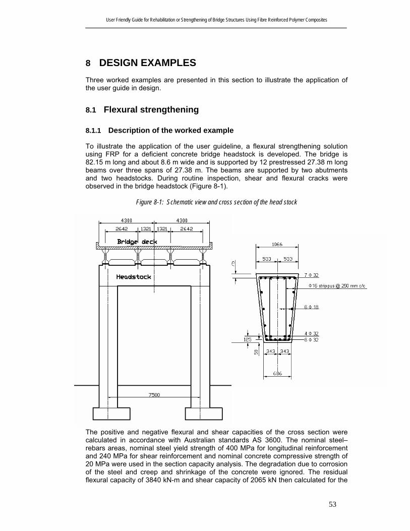
User Friendly Guide for Rehabilitation or Strengthening of Bridge Structures Using Fibre Reinforced Polymer Composites
53
8 DESIGN EXAMPLES Three worked examples are presented in this section to illustrate the application of the user guide in design.
8.1 Flexural strengthening
8.1.1 Description of the worked example
To illustrate the application of the user guideline, a flexural strengthening solution using FRP for a deficient concrete bridge headstock is developed. The bridge is 82.15 m long and about 8.6 m wide and is supported by 12 prestressed 27.38 m long beams over three spans of 27.38 m. The beams are supported by two abutments and two headstocks. During routine inspection, shear and flexural cracks were observed in the bridge headstock (Figure 8-1).
Figure 8-1: Schematic view and cross section of the head stock
The positive and negative flexural and shear capacities of the cross section were calculated in accordance with Australian standards AS 3600. The nominal steel–rebars areas, nominal steel yield strength of 400 MPa for longitudinal reinforcement and 240 MPa for shear reinforcement and nominal concrete compressive strength of 20 MPa were used in the section capacity analysis. The degradation due to corrosion of the steel and creep and shrinkage of the concrete were ignored. The residual flexural capacity of 3840 kN-m and shear capacity of 2065 kN then calculated for the

User Friendly Guide for Rehabilitation or Strengthening of Bridge Structures Using Fibre Reinforced Polymer Composites
54
headstock in accordance with Austroads Bridge Design code Clause 5.8.1.2, Clause 5.8.1.3 and Clause 5.8.2. Although calculated applied bending moments and shear force in serviceability limit state are relatively lower than structural capacity of the headstock, a decision was made to strengthen the headstock for ultimate bending moment. The strengthening target is decided to be set for ultimate bending moment of 5200 kN-m
8.1.2 Design material properties
The guideline suggests that the design ultimate tensile strength should be determined using the environmental reduction factor for FRP materials. The reduction factors are mainly based on type of fibre and environmental conditions. Similarly it is suggested to reduce the design rupture strain for environmental-exposure conditions. A reduction factor for carbon fibre in aggressive environment, CE, of 0.85 is used. The design material properties for the headstock according to the guide are listed in Table 8-1.
Table 8-1: Design material properties for flexural and shear strengthening Material Design Strength
(MPa) Modulus of
Elasticity (MPa) Allowable strain
Concrete 20 (γ =0.85) 22,610* 0.003 Steel reinforcement 400 200,000 0.002
CFRP strips (flexural) 0.85x2800=2,380 165,000 0.85x0.017=0.01445 CFRP wrapping (shear) 0.85x3500=2,975 230,000 0.85x0.015=0.01275 * The long term modulus of elasticity of 11305 was used to account for creep of concrete
8.1.3 Initial situation
It was noted that the effect of the initial load prior to strengthening should be considered in the calculations using the theory of elasticity and with the service moment acting on the critical beam section during strengthening.
Figure 8-2: Initial situation
The initial strain distribution of the member may then be evaluated and considered in strengthening calculations. As the service bending moment is typically greater than

User Friendly Guide for Rehabilitation or Strengthening of Bridge Structures Using Fibre Reinforced Polymer Composites
55
the cracking moment, the calculation is based on a cracked section. The initial strain distribution of the headstock was calculated based on structural analysis for service loading condition, long-term modulus of elasticity and the cracked section.
777=ox mm cococ
ooco IIE
xM×
××==⇒
22610777102758 6
ε
( ) ( ) 112211 1039.2823803010757775521110106.1 ×=××+−××−+×=coI
0004.022610
777102758 6
=×
××==⇒
cococ
ooco IIE
xMε
00046.0777
77716760004.0 =−
×=−
=⇒o
ocoo x
xhεε
8.1.4 Capacity of the strengthened beam
The cross section analysis indicated that the failure mode of the beam section of the headstock would be the yielding of the longitudinal steel reinforcement followed by concrete crushing, while the FRP is intact. This is the most desirable failure mode, which satisfy the safety requirements in ultimate state for a reinforced concrete section. The design bending moment for the strengthened member is then calculated based on well-established principles of flexural design of a reinforced concrete beam. The design principals are shown in Figure 8-3.
Figure 8-3: Internal strain and stress distributions for the beam cross section of the headstock
u
h-x d-
x
εε f o
εcu
s1εγ
x
c0.85 f '
f s1s1s1s1f = E ε
f = E εf f f ff
Strain Distribution Stress Distribution
4 FRP strips of 120 x 1.4 mm
6 F 32
7 F 32
4 F 32
f = E εs2 s2 s2
d 2
s2f
Neutral Axis
k d
= x
The section design for failure mode of yielding steel followed by concrete crushing
20=′cf
26100057000 =′= cc fE
0055.0876*1676
803011 ==≡
bdAs
sρ

User Friendly Guide for Rehabilitation or Strengthening of Bridge Structures Using Fibre Reinforced Polymer Composites
56
0038.0876*1676
552122 ==≡
bdAs
sρ
00045.0876*1676
672==≡
bdAf
fρ
1800002310004.1165000 >=×=ff tnE
9.045.023100090000
01445.060190000
601
<=⎟⎠⎞
⎜⎝⎛
×=⎟
⎟⎠
⎞⎜⎜⎝
⎛=
fffum tnEε
κ
ocuf xxh εεε −
−=
ocus xdx
εεε −−
= 22
bfEAEAfA
xc
sssfffsys′
−+=
γ
εε
85.0221
( )[ ] 85.085.028007.085.065.0 =⇒≤−′−=≤ γγ cf (Clause 5.8.2, Austroads Bridge
design code)
x =258 mm, 01445.00119.0 <=fε 0007.02 =sε 4.016.0 <=uk
8.0=φ (Table 5.2.3, Austroads Bridge design code)
⎥⎦
⎤⎢⎣
⎡⎟⎠
⎞⎜⎝
⎛ −+⎟⎠
⎞⎜⎝
⎛ −+⎟⎠
⎞⎜⎝
⎛ −=222
8.0 1222dk
hEAdk
dfAddk
EAM ufff
usys
usssuo
γεψ
γγεφ
( ) ( )( ) mkNM uo −=⎥
⎦
⎤⎢⎣
⎡−××××
+−×+−××= 5203
11016760119.016500067285.011016004008030751100007.02000005621
8.0φ
8.1.5 Anchorage
Experimental investigations show that the FRP rupture is a rare event and delamination of FRP strips is more likely occur before stress in the FRP reach the ultimate level. Debonding implies the complete loss of composite action between the concrete and FRP laminates. Bond failure will be a brittle failure and should be prevented at any cost. The user guide place a limitation on the strain level in the laminate to prevent delamination of FRP from the concrete substrate.
1800002310004.1165000 >=×=ff tnE
9.054.023100090000
0119.060190000
601
<=⎟⎠⎞
⎜⎝⎛
×=⎟
⎟⎠
⎞⎜⎜⎝
⎛=
fffum tnEε
κ

User Friendly Guide for Rehabilitation or Strengthening of Bridge Structures Using Fibre Reinforced Polymer Composites
57
0079.001445.054.0 =×=≤−−
= fumocuf xxh εκεεε
NAET fff 8742856720079.0165000 =××== ε
cs
ff
IxhAM
T)( −
=α
mkNMM−=⇒
×
−××= 19083
1063.2)4421676(67253.14874285 11 > Mu
The user guide also recommends considering the following failure modes to prevent de-lamination of FRP, depending on the starting point of the de-bonding process.
• De-bonding in an un-cracked anchorage zone; • De-bonding caused at flexural cracks; and • De-bonding caused at shear cracks.
Approach 1: Verification of end anchorage, Strain limitation in the FRP reinforcement, This approach involves two independent steps: first, the end anchorage should be verified based on the shear stress-slip constitutive law at the FRP-concrete interface. Then strain limitation should be applied on the FRP to ensure that bond failure far from the anchorage is prevented. In the following the model of Holzenkamper (1994) as modified by Neubauer and Rostasy (1997) is presented
ctmffbcfa ftEbkkcN 1max, α= (N)
ctm
ffb fc
tE
2max, =l (mm)
mmb 24022
4.1165000max, =
××
=l
181.0
4004801
6864802
06.1
4001
206.1 <=
+
−=
+
−=
f
f
b bb
b
k
kNftEbkkcN ctmfffbcfa 18824.11650004800.10.164.09.01max, =××××××== α
Theoretical cut off point
cs
fffa I
xhAMN
)(max,
−=
α
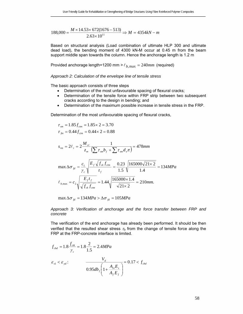
User Friendly Guide for Rehabilitation or Strengthening of Bridge Structures Using Fibre Reinforced Polymer Composites
58
mkNMM−=⇒
×−××
= 43541063.2
)5131676(67253.14000,188 11
Based on structural analysis (Load combination of ultimate HLP 300 and ultimate dead load), the bending moment of 4300 kN-M occur at 0.45 m from the beam support middle span towards the column. Hence the anchorage length is 1.2 m Provided anchorage length=1200 mm > mmb 240max, =l (required) Approach 2: Calculation of the envelope line of tensile stress The basic approach consists of three steps
• Determination of the most unfavourable spacing of flexural cracks; • Determination of the tensile force within FRP strip between two subsequent
cracks according to the design in bending; and • Determination of the maximum possible increase in tensile stress in the FRP.
Determination of the most unfavourable spacing of flexural cracks,
70.3285.185.1 =×== ctmsm fτ 88.0244.044.0 =×== ctmfm fτ
( ) mmdbz
Ms
ssmfsmm
crtrm 478122 =
+==
∑ ∑ πττl
MPat
ffEc
f
ctmckf
cfd 134
4.1221165000
5.123.0max 1 =
×==∆
γσ
.210221
4.116500044.12max, mmff
tEc
ctmck
ffb =
××
==l
MPaMPa fdfd 105134max =∆>=∆ σσ
Approach 3: Verification of anchorage and the force transfer between FRP and concrete The verification of the end anchorage has already been performed. It should be then verified that the resulted shear stress τb from the change of tensile force along the FRP at the FRP-concrete interface is limited.
MPaf
fc
ctkcbd 4.2
5.128.18.1 ===
γ
yds εε <1 : cbd
ff
ssf
d f
EAEA
db
V<=
⎟⎟⎠
⎞⎜⎜⎝
⎛+
17.0
195.0 1
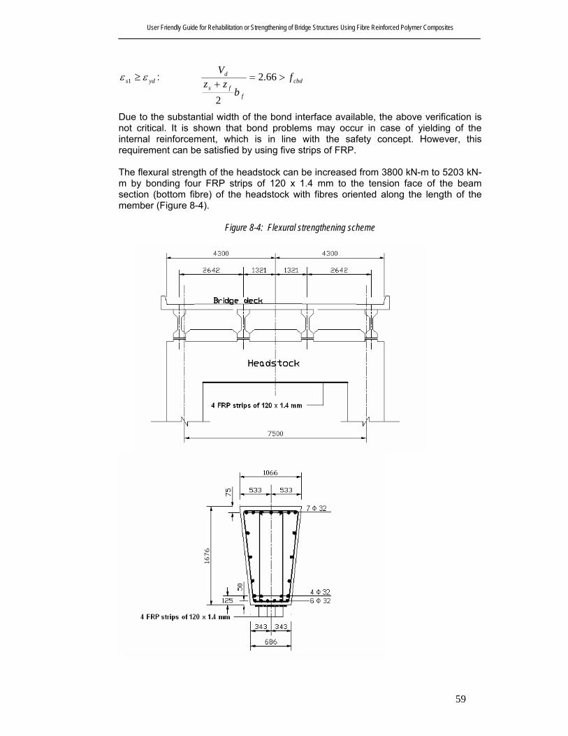
User Friendly Guide for Rehabilitation or Strengthening of Bridge Structures Using Fibre Reinforced Polymer Composites
59
yds εε ≥1 : cbd
ffs
d fb
zzV
>=+
66.2
2
Due to the substantial width of the bond interface available, the above verification is not critical. It is shown that bond problems may occur in case of yielding of the internal reinforcement, which is in line with the safety concept. However, this requirement can be satisfied by using five strips of FRP. The flexural strength of the headstock can be increased from 3800 kN-m to 5203 kN-m by bonding four FRP strips of 120 x 1.4 mm to the tension face of the beam section (bottom fibre) of the headstock with fibres oriented along the length of the member (Figure 8-4).
Figure 8-4: Flexural strengthening scheme

User Friendly Guide for Rehabilitation or Strengthening of Bridge Structures Using Fibre Reinforced Polymer Composites
60
8.2 Shear Strengthening
8.2.1 Description of the worked example
A shear strengthening solution is developed using FRP wrapping for a deficient headstock. The shear capacities of the cross section were calculated in accordance with Australian standards AS 3600. The residual shear capacity of 2065 kN then calculated Although calculated applied shear force in serviceability limit state are relatively lower than structural capacity of the headstock, a decision was made to strengthen the headstock for ultimate shear force. The strengthening target is decided to set for ultimate shear force of 2600 kN.
8.2.2 Nominal shear strength
The nominal shear strength of an FRP-strengthened concrete member can be determined by adding the contribution of the FRP reinforcement to the contributions from the shear steel reinforcement and the concrete. It is also suggested that an additional reduction factor of fψ =0.95, to be applied to the shear contribution of the FRP reinforcement.
( )uffusucu VVVV ψφφ ++=
fuf εε 75.0004.0 ≤=
009.001275.075.0004.0 =×<=fε
MPaEf fff 920230000004.0 =×== ε
2436167613.0122 mmwntA fffv =×××==
kNs
dfAV
f
fffvf 400)1(920436
)cos(sin=×=
+=
αα
( ) kNVVVV uffusucu 2598240095.0147514757.0)( =××++=++= ψφφ
kNVkNVu 26002598 * =≈=φ The shear strength of the headstock can be increased from 2065 kN to 2600 kN by complete wrapping of the beam with 2 layers of 0.13 mm thick carbon fibres oriented along the transverse axis of the beam section (Figure 8-5).

User Friendly Guide for Rehabilitation or Strengthening of Bridge Structures Using Fibre Reinforced Polymer Composites
61
Figure 8-5: Shear strengthening scheme

User Friendly Guide for Rehabilitation or Strengthening of Bridge Structures Using Fibre Reinforced Polymer Composites
62
8.3 Axial Compression Strengthening
8.3.1 Description of the worked example
A circular column of 500 mm diameter of a bridge requires an additional 1200 kN of axial compression strength ( uN∆ = 1200). A method of strengthening the column using FRP is sought. The nominal compressive strength of 25 MPa is assumed.
Figure 8-6: Cross section of the column
8.3.2 Design material properties
The guideline suggests that the design ultimate tensile strength should be determined using the environmental reduction factor for FRP materials. The reduction factors are mainly based on type of fibre and environmental conditions. Similarly it is suggested to reduce the design rupture strain for environmental-exposure conditions. A reduction factor for carbon fibre in aggressive environment, CE, of 0.85 is used. The design material properties for the headstock according to the guide are listed in Table 8-2.
Table 8-2: Design material properties for axial compression strengthening Material Design Strength
(MPa) Modulus of
Elasticity (MPa) Allowable strain
Concrete 25 28,260* 0.003 Steel reinforcement 400 200,000 0.002
CFRP wrapping (shear) 0.85x3500=2,975 230,000 0.85x0.015=0.01275 The long term modulus of elasticity of 14130 may be used to account for creep of concrete
8.3.3 Nominal axial strength
The strength-design approach requires that the design axial strength of a member is not less than the design action effect. An additional axial compression strength, φ∆Nu, can be determined using following equation:
500 mm
2 layers of 0.3 mm FRP wrapping 8 Y 24 deformed bar

User Friendly Guide for Rehabilitation or Strengthening of Bridge Structures Using Fibre Reinforced Polymer Composites
63
( )[ ]stgcccf AAffNu −−=∆ )(85.075.0 ''ψφφ
0048.0500
3.0244=
××==
htn f
fρ
fuf εε 75.0004.0 ≤= =0.01275 x 0.75=0.0096
21.22
230000004.00048.00.122
=×××
=== fffaffal
Eff
ερκρκ MPa
6.3725.12521.22
2521.29.7125.22525.129.7125.2
'''' =⎥
⎦
⎤⎢⎣
⎡−−+=
⎥⎥⎦
⎤
⎢⎢⎣
⎡−−+=
c
l
c
lccc
f
f
f
fff
( )[ ] 14123619196349)256.37(95.085.09.085.0 =−−××=∆Nuφ kN

User Friendly Guide for Rehabilitation or Strengthening of Bridge Structures Using Fibre Reinforced Polymer Composites
64
9 NOTAION A = cross-sectional area of a member (mm 2) A fv = total area of FRP shear reinforcement (mm 2) Af = total area of FRP reinforcement (mm 2) Afib = total area of the fibre on the FRP reinforcement (mm 2) Ag = gross area of section (mm 2) Am = total area of the matrix in FRP reinforcement (mm 2) As1 = total area of tensile longitudinal reinforcement (mm 2) As2 = total area of compressive longitudinal reinforcement (mm 2) As = area of non prestress reinforcement (mm 2) Ast = total area of longitudinal reinforcement (mm 2) Asv = the cross-sectional area of shear reinforcement (mm 2) b = average width at the cross section (mm) bf = width of FRP reinforcement (mm) bw = web width of diameter of circular section (mm) CE = environmental reduction factors d = distance from extreme compression fiber to the centroid of the non
prestresses steel tension reinforcement (mm) df = depth of shear reinforcement as shown in Figure 6-5 (mm) ds = diameter of steel reinforcement (mm) Ec = modulus of elasticity of the concrete (MPa) Ef = modulus of elasticity of FRP (MPa) Es = modulus of elasticity of reinforcement steel (MPa) f’c = specified compressive strength of concrete (MPa) fcbd = design bond shear strength of concrete (MPa) f’cc = apparent compressive strength of confined concrete (MPa) fcd = design value of the concrete compressive strength (MPa) fck = characteristic value of the concrete compressive strength (MPa) fctk = characteristic value of the concrete tensile strength (MPa) fctm = mean value of the concrete tensile strength (MPa) ff = stress level in the FRP reinforcement (MPa) ffd = design value of the FRP reinforcement tensile strength (MPa) ff,,s = stress level in FRP reinforcement caused by a moment within elastic
range of the member, (MPa) ffu = the FRP ultimate tensile strength (MPa) f *fu = the FRP ultimate tensile strength reported by manufacturer (MPa) fl = confining pressure due to FRP jacket (MPa) fs = stress in non prestressed steel reinforcement (MPa) fs,s = stress level in non prestressed steel reinforcement at service loads, (MPa) fy = specified yield strength of non prestressed steel reinforcement (MPa) fsy.f = the yield strength of shear reinforcement (MPa) fyd = design value of the steel yield strength (MPa) h = total depth of the member I = a second moment area of a member (mm 4) I cs = moment of inertia of transformed cracked section after strengthening
(mm4) Ico = moment of inertia of transformed cracked section before strengthening
(mm 4)

User Friendly Guide for Rehabilitation or Strengthening of Bridge Structures Using Fibre Reinforced Polymer Composites
65
k = ratio of the depth of the neutral axis to the reinforcement depth in elastic analysis of the cross section
k1 = modification factor applied to κv to account for the concrete strength k2 = modification factor applied to κv to account for the wrapping scheme kb = size factor kc = concrete compaction factor ku = the neutral axis parameter at ultimate state Le = active bond length of FRP laminate
bl = bond length
max,bl = maximum anchorage length
tl = transmission length M * = applied moment at the section (kN-m) max∆σ fd = design value of maximum possible increase in FRP tensile stress
between two subsequent cracks (MPa) Mcr = cracking moment Mo = acting moment during strengthening (kN-m) Md = the decompression moment MRd = resisting design moment (kN-m) FIB 14, 2002 Muo = nominal design flexural strength (kN-m) Nf = force in FRP N* = the required axial strength Nfa = FRP force to be anchored Nfa, max = maximum anchorable force Ns1 = force in tensile steel reinforcement Nu = nominal design axial strength R n = nominal strength of member R nθ = nominal strength of member subjected to the elevated temperature
associated with a fire S DL = dead load effect s f = maximum spacing of FRP S LL = live load effect s rm = mean value of crack spacing tf = nominal thickness of the FRP reinforcement (mm) V * = applied shear force at the section (kN) Vd = the shear force which would occur at a section when the bending moment
at the section was equal to decompression moment (N) Vt = a shear force producing principle tensile stress (N) Vu = nominal shear strength of a member (N) Vuc = nominal shear strength provided by concrete with steel flexural
reinforcement (N) Vuf = nominal shear strength provided by FRP reinforcement (N) Vus = nominal shear strength provided by steel stirrups (N) w f = width of FRP reinforcing plies (mm) x = depth of the compression zone Z = the first moment of area of an uncracked cross-section (mm 3) z m = mean lever arm of internal forces α = reduction factor to account for the influence of inclined cracks on the
bond strength αf = modular ratio for non-prestressed steel

User Friendly Guide for Rehabilitation or Strengthening of Bridge Structures Using Fibre Reinforced Polymer Composites
66
β = a coefficient with or without numerical subscript ε’cc = maximum useable compressive strain of FRP confined concrete εco = initial concrete strain in the extreme compressive fibre before
strengthening, or unconfined concrete strain at peak stress εcu = ultimate concrete strain εf = FRP strain εf, s = FRP strain at service loads εf, min =minimum allowable FRP strain at ultimate εfd,e = design value of effective FRP strain εfe = effective FRP strain εfk,e = characteristic value of effective FRP strain εfu = the FRP ultimate strain ε*
fu = the FRP ultimate strain reported by manufacturer εfu ,c = FRP strain in the critical section at ultimate. εo = initial strain at the extreme tensile fibre before strengthening εs = strain in steel reinforcement εs,s = strain in steel reinforcement at service loads εs1 = tensile steel strain εs2 = compressive steel strain εsu = ultimate steel strain ε y = yield strain of the steel reinforcement ε yd = design value of the yield strain of the steel reinforcement φ = strength-reduction factor γ = multiplier to determine the intensity of an equivalent rectangular stress
distribution for concrete κa = efficiency factor for FRP confinement (based on the section geometry) κm = bond dependant coefficient for flexure κv = bond dependant coefficient for shear ρ f = FRP reinforcement ratio ρ s1 = ratio of non-prestressed tensile reinforcement ρ s2 = ratio of non-prestressed compressive reinforcement σ fd = design value of FRP tensile stress σ fad = design value of FRP tensile stress at the end anchorage (MPa) σ fad,max = design value of maximum anchrable FRP tensile stress (MPa) τ b = bond shear stress τ fm = mean bond stress of the FRP τ sm = mean bond stress of the steel reinforcement ψ f = FRP strength reduction factor

User Friendly Guide for Rehabilitation or Strengthening of Bridge Structures Using Fibre Reinforced Polymer Composites
67
10 REFERENCES American Concrete Institute Committee 440, (2002). “Guide for the design and
construction of externally bonded FRP systems for strengthening concrete structures”
American National Research Council, 1991, “Life Prediction Methodologies for Composite Materials,” Committee on Life Prediction Methodologies for Composites, NMAB-460, National Materials Advisory Board, Washington D.C.
AS3600 (2002), "Concrete Structures", Australian Standard, Standards Association, Australia,
Austroads (1992), "Bridge design code", The Association of State and Territory and Federal road and traffic authorities in Australia,
Bakis, C.E.; Bank, L.C.; Brown, V.L.; Cosenza, E.; Davalos, J.F.; Lesko, J.J.; Machida, A.; Rizkalla, S.H.; and Triantifillou, T.C. 2002 “Fiber-Reinforced Polymer Composites for Construction-State-of-the-Art Review,” Journal of Composites in Construction, V. 6, No. 2, pp. 73-87.
Ballinger, C., Maeda, T. and Hoshijima, T. (1993) “Strengthening of reinforced concrete chimneys, columns and beams with carbon fiber reinforced plastics” Proceedings of the International Symposium on Fiber-Reinforced-Plastic Reinforcements for Concrete Structures, ACI SP-138, pp. 243-248
Benmokrane, B., and Rahman, H., Eds., 1998, Durability of Fiber Reinforced Polymer (FRP) Composites for Construction, University of Sherbrooke, Canada.
Blaschko, M. and Zilch, K. (1999), “Rehabilitation of concrete structures with CFRP strips glued into slits” Proceedings of the 12th International Conference on Composite Materials, Paris, July 5-9.
Brosens, K. and Van Gemert, D. (1997) “Anchoring Stresses between Concrete and Carbon Fibre Reinforced Laminates”, Non-metallic (FRP) Reinforcement for Concrete Structures, Proceedings of the Third International Symposium, Oct., Vol. 1, pp. 271-278
Canadian Standard Association (CSA), 2002, “Design and Construction of Building Components with Fiber Reinforced Polymer,” CSA S806-02, Toronto, ON, Canada, 177 pp.
Candappa, D. (2000). “The constitutive behavior of high strength concrete under lateral confinement, PhD thesis, Monash University, Australia.
CEN (1994), Eurocode 1: Basis of design and actions on structures – Part 1: Basis of design. ENV 1991-1, Comité Européen de Normalisation, Brussels, Belgium.
Chai, Y. H., Priestley, M. J. N. and Seible, F. (1991), “Seismic retrofit of circular bridge columns for enhanced flexural performance”, ACI Structural Journal, 88(5), 572-584
Chajes, M., Januska, T., Mertz, D., Thomson, T., and Finch, W. (1995) “Shear Strengthening of Reinforced Concrete Beams Using Externally Applied Composite Fabrics”, ACI Structural Journal, V. 92, No. 3, pp. 295-303.
Deuring, M. (1993), “Strengthening of RC with prestressed fiber reinforced plastic sheets”, EMPA Research Report 224, Dübendorf, Switzerland (in German).
Dolan, C.W., Rizkalla, S.H., and Nanni, A. (Editors), 1999, Fourth International Symposium on Fiber Reinforced Polymer Reinforcement for Reinforced Concrete Structures. American Concrete Institute, SP-188, Farmington Hills, Michigan.
EQE (1995). “The January 17, 1995 Kobe Earthquake." EQE Summary Report, <http://www.eqe.com/publications/kobe/building.htm> (October 22, 2003).

User Friendly Guide for Rehabilitation or Strengthening of Bridge Structures Using Fibre Reinforced Polymer Composites
68
Fardis, M.N., and Khalili, H. (1981) “Concrete Encased in Fiberglass Reinforced Plastic,” ACI Journal, 78(6), pp. 440-446.
FIB Bulletin 14 (2002) “Externally bonded FRP reinforcement for RC structures”, Task group 9.3, International Federation of Structural Concrete (FIB).
Fleming, C.J., and King G.E.M. (1967) “The Development of Structural Adhesives for Three Original Uses in South Africa”, RILEM International Symposium, Synthetic Resins in Building Construction, Paris, pp.75-92.
Gang Rao, H.V.S., and Vijay, P.V. (1998) “Bending Behavior of Concrete Beams Wrapped with Carbon Fabric” Journal of Structural Engineering, V.124, No.1, pp. 3-10
[Holzenkämpfer, P. (1994), Ingenieurmodelle des verbundes geklebter bewehrung für betonbauteile. Dissertation, TU Braunschweig (In German)].
Japan Concrete Institute (JCI), (1997) Non-metallic (FRP) Reinforcement for Concrete Structures, 1 and 2, Tokyo, Japan.
Japan Concrete Institute (JCI) (1998) “Technical Report on Continuous Fiber Reinforced Concrete,” TC 952: Committee on Continuous Fiber reinforced Concrete, Tokyo.
Japan Society of Civil Engineers (JSCE) (2001) “Recommendations for Upgrading of Concrete Structures with Use of Continuous Fiber Sheets,” Concrete Engineering Series, No. 41, Tokyo, Japan, 250 pp.
Kachlakev, D., and McCurry, D. (2000) “Testing of Full-Size Reinforced Concrete Beams Strengthened with FRP Composites: Experimental Results and Design Methods Verification,” Report No. FHWA-OR-00-19, U.S. Department of Transportation Federal Highway Administration
Kalra, R. and Neubauer, U. (2003). “Strengthening of the Westgate Bridge with Carbon Fibre Composites - A Proof Engineer’s Perspective” 21st Biennial Conference of the concrete institute of Australia, Brisbane, Australia, pp. 245-254
Katsumata, H., Kobatake, Y., and Takeda, T. (1987) “A Study on the Strengthening with Carbon Fiber for Earthquake-Resistant Capacity of Existing Concrete Columns,” Proceedings from the Workshop on Repair and Retrofit of Existing Structures, U.S.-Japan Panel on Wind and Seismic Effects, U.S.-Japan Cooperative Program in Natural Resources, Tsukuba, Japan, pp. 1816-1823.
Khalifa, A., Gold, W., Nanni, A., and Abel-Aziz M. (1998). “Contibution of Externally Bonded FRP to the Shear Capacity of RC Flexural Members", Journal of composites in Construction, Vol. 2, No. 4 pp. 195-203
Lokuge, W. P., Sanjayan, J. G., and Setunge, S. (2004). “Stress strain model for laterally confined concrete", Approved for publication in the Journal of Materials in Civil Engineering, ASCE.
Lorenzis, L. D. (2001). “A comparative study of models on confinement of concrete cylinders with FRP composites" Research report, Chalmers University of Technology, Goteborg, Sweden.
Maeda, A., Asano, Y., Ueda, T, and Kakuta, Y. (1997) “A study on Bond Mechanism of Carbon Fiber Sheet”, Non-metallic (FRP) Reinforcement for Concrete Structures, Proceedings of the Third International Symposium, Oct., Vol. 1, pp. 271-278
Malvar, L., 1998, “Durability of Composites in Reinforced Concrete,” Proceedings of the First International Conference on Durability of Composites for Construction, Aug., Sherbrooke, Canada, pp. 361-372.
Malvar, L., Warren, G., and Inaba, C., (1995) “Rehabilitation of Navy Pier Beams With Composite Sheets”, Second FRP International Symposium, Non-Metallic (FRP) Reinforcements for Concrete Structures, Aug., Gent, Belgium, pp. 533-540.

User Friendly Guide for Rehabilitation or Strengthening of Bridge Structures Using Fibre Reinforced Polymer Composites
69
Mandell, J.F., 1982, “Fatigue Behavior of Fibre-Resin Composites,” Developments in Reinforced Plastics, Applied Science Publishers, London, England, V. 2, pp. 67-107.
Mander, J. B., Priestly, M. J. N. and Park, R. (1988), “Theoretical Stress-Strain Model for Confined Concrete”, Journal of Structural Engineering, ASCE, Vol.114, No. 8, pp. 1804-1826
Master Builders Technologies (MBT), Australia, MBrace Design CD ROM, Version 3.0.
Matthys, S., Taerwe, L. and Audenaert, K. (1999), “Tests on axially loaded concrete columns confined by FRP sheet wrapping”, Proceedings of the 4th International Symposium on FRP for Reinforced Concrete Structures, Baltimore, USA, 217-228.
Meier, U., 1987, “Bridge Repair with High Performance Composite Materials,” Material und Technik, V. 4, pp. 125-128 (in German)
Mirmiran, A. and Shahawy, M., (1997), “Behavior of concrete columns confined by fiber composites”, Journal of Structural Engineering, ASCE, 123(5), 583-590
Monti, G., Nisticò, N. and Santini, S. (2001), “Design of FRP jackets for upgrade of circular bridge piers”, Journal of Composites for Construction, ASCE, in print
Mutsuyoshi, H., Ishibashi, T., Okano, M. and Katsuki, F. (1999), “New design method for seismic retrofit of bridge columns with continuous fiber sheet – Performance-based design”, Fiber Reinforced Polymer Reinforcement for Reinforced Concrete Structures, ed. C. W. Dolan, S. H. Rizkalla and A. Nanni, ACI Report SP-188. Detroit, Michigan, 229-241.
Nanni, A. and Bradford, N. M. (1995), “FRP jacketed concrete under uniaxial compression”, Construction and Building Materials, 9(2), 115-124
Nanni, A., 1995, “Concrete Repair with Externally Bonded FRP Reinforcement”, Concrete International, Vol. 17 No.6, pp.22-26
Nanni, A.; Focacci, F.; and Cobb, C.A., 1998, “Proposed Procedure for the Design of RC Flexural Members Strengthened with FRP Sheets,” Proceedings, ICCI-98, Jan., Tucson, Ariz, V. 1, pp. 187-201
Neale, K.W., 2000, “FRPs for Structural Rehabilitation: A Survey of Recent Progress,” Progress in Structural Engineering and Materials, Vol. 2, No. 2, pp. 133-138
Neubauer, U. and Rostásy, F. S. (1997), “Design aspects of concrete structures strengthened with externally bonded CFRP-plates”. In Concrete+Composites, Proceedings of the 7th International Conference on Structural Faults and Repair, 2, 109-118.
Neubauer, U. and Rostásy, F. S. (1999), “Bond failure of concrete fibre reinforced polymer at inclined cracks- experiments and fracture mechanics model” Proceedings of the 4th International Conference on Fiber Reinforced Polymer Reinforcement for Concrete Structures, Eds. C.W. Dolan, S. H. Rizkalla and A. Nanni, ACI, Michigan, USA, 369-382,
[Niedermeier, R. (2000), Zugkraftdeckung bei klebearmierten bauteilen (Envelope line of tensile forces while using externally bonded reinforcement). Doctoral Dissertation, TU München, (In German)]
Norris, T., Saadatmanesh, H., and Ehsani, M. (1997) “Shear and Flexural Strengthening of R/C Beams with Carbon Fiber Sheets,” Journal of Structural Engineering, V. 123, No. 7, pp. 903-911
Odagiri, T., Matsumoto, K., and Nakai H. (1997) “Fatigue and Relaxation Characteristics of Continuous Aramid Fiber Reinforced Plastic Rods”, Third International Symposium on Non-Metallic (FRP) Reinforcement for Concrete Structures (FRPRCS-3), Japan Concrete
Picher, F., Rochette, P. and Labossière, P. (1996), “Confinement of concrete cylinders with CFRP”, Proceedings of 1st International Conference on Composite Infrastructures, Tucson, Arizona, USA, 829-841

User Friendly Guide for Rehabilitation or Strengthening of Bridge Structures Using Fibre Reinforced Polymer Composites
70
Priestley, M., Seible, F., and Calvi, G. (1996), Seismic Design and Retrofit of Bridges, John Wiley and Sons, New York, NY
Railway Technical Research Institute (RTRI), 1996, “Design and Construction Guidelines for Seismic Retrofitting of Railway Viaduct Columns Using Aramid Fiber Sheets,” Tokyo (in Japanese)
Railway Technical Research Institute (RTRI), 1996, “Design and Construction Guidelines for Seismic Retrofitting of Railway Viaduct Columns Using Carbon Fiber Sheets,” Tokyo (in Japanese)
[Rostasy, F.S., 1987, “Bonding of Steel and GFRP Plates in the Area of Coupling Joints. Talbrucke Kattenbusch.”, Research Report No. 3126/1429, Federal Institute for Materials Testing, Braunschweig, Germany (in German)]
Roylance, M., and Roylance, O., 1981, “Effect of Moisture on the Fatigue Resistance of an Aramid-Epoxy Composite,” Organic Coatings and Plastics Chemistry, American Chemical Society, Washington, D.C., V. 45, pp. 784-788.
Saadatmanesh, H., and Ehsani, M., ed., 1998, Second International Conference on Composites in Infrastructure, ICCI, Tucson, Ariz., V. 1 & 2, 1506 pp.
Saadatmanesh, H., Ehsani, M. R. and Li, M. W. (1994), “Strength and ductility of concrete columns externally reinforced with fiber composite straps”, ACI Structural Journal, 91(4), 434-447
Sato, Y., Ueda, T., Kakuta, Y., and Tanaka, T. (1996) “Shear Reinforcing Effect of Carbon Fiber Sheet Attached to Side of Reinforced Concrete Beams” , Advanced Composite Materials in Bridges and Structures, M.M. El-Badry, ed., pp. 621-627
Seible, F., Burgueño, R., Abdallah, M. G. and Nuismer, R. (1995 b), “Advanced composite carbon shell systems for bridge columns under seismic loads Progress in research and practice”, Proceedings of National Seismic Conference on Bridges and Highways, San Diego, CA, USA.
Seible, F., Priestley, M. J. N. and Innamorato, D. (1995 a), “Earthquake retrofit of bridge columns with continuous fiber jackets” Design guidelines, Advanced composite technology transfer consortium, 2, Report No. ACTT-95/08, University of California, San Diego, USA
Seible, F., Priestley, M. J. N. and Hegenier, G. A., and Innamorato, D. (1997), “Seismic Retrofit of RC with continuous fiber jackets” Journal of Composites for Construction, No.1, pp. 52-62
Sheheta, E., Morphy, R., and Rizkalla, S. 1999, Fourth International Symposium, Fiber Reinforced Polymer Reinforcement for Concrete Structures, SP-188, American Concrete Institute, Farmington Hills, Mich., pp. 157-167.
Shepherd, B. and Sarkady, A. (2002) “Carbon Fibre Fabric Strengthening of Little River Bridge” Proc. IABSE Symposium, Melbourne Australia, Sept 11-13, 2002
Sika® CarboDur Composite Strengthening Systems, Australia, CD ROM. Triantafillou, T. C. (1998a), “Shear strengthening of reinforced concrete beams using
epoxy bonded FRP composites” ACI Structural Journal, 95(2), 107-115. Triantafillou, T. C. (2001), “Seismic retrofitting of structures using FRPs” Progress in
Structural Engineering and Materials Vol. 3 No. 1 pp 57-65. Triantafillou, T. C. and Antonopoulos, C. P. (2000), “Design of concrete flexural
members strengthened in shear with FRP”. ASCE Journal of Composites for Construction, 4(4), 198- 205.
Triantafillou, T. C., Deskovic, N. and Deuring, M. (1992), “Strengthening of concrete structures with prestressed fiber reinforced plastic sheets”, ACI Structural Journal, 89(3), 235-244.
[Wolf R. and Miessler H. J. (1989) HLV-Spannglieder in der praxis, erfahrungen mit glasfaserverbundstaben. Beton, 2, pp.47-51]

User Friendly Guide for Rehabilitation or Strengthening of Bridge Structures Using Fibre Reinforced Polymer Composites
71
Xiao, Y. and Wu, H. (2000) “Compressive behavior of concrete confined by carbon fiber composite jackets" Journal of Materials in Civil Engineering, Vol. 12, No. 2, pp. 139-146.
Yamaguchi, T., Kato, Y., Nishimura, T., and Uomoto, T. (1997) “Creep Rupture of FRP Rods Made of Aramid, Carbon and Glass Fibers”, FRPRCS-3, Third International Symposium on Non-Metallic FRP Reinforcement for Concrete Structures, Sapporo, Japan, V. 2, pp. 179-186.

User Friendly Guide for Rehabilitation or Strengthening of Bridge Structures Using Fibre Reinforced Polymer Composites
72
11 AUTHORS BIOGRAPHY Dr Abe Nezamian, Education: PhD, Monash University, Australia 2003, B.Sc. (Hons)
Azad University, Iran 1990 Professional Experience: Nine years of experience in consulting engineering
companies. Research Interests: Rehabilitation of aged concrete structures, composite
structures, and concrete filled tubular steel columns Dr Sujeeva Setunge, Education: PhD, Monash University, Australia (1993), B.Sc.
Eng.(Hons) Sri Lanka (1985) Professional Experience: 1 year in Civil Engineering Construction and 15 years in
Academia. Research Interests: Infrastructure asset management, creep and shrinkage
of concrete, innovative construction materials and composites, high strength and high performance concrete