chapter 22 bridge rehabilitation
TRANSCRIPT
NDOT STRUCTURES MANUAL
September 2008
Chapter 22
BRIDGE REHABILITATION

BRIDGE REHABILITATION September 2008
22-i
Table of Contents
Section Page 22.1 INTRODUCTION..................................................................................................... 22-1
22.1.1 Importance................................................................................................ 22-1 22.1.2 Scope of Work Definitions ........................................................................ 22-1 22.1.3 Highway Bridge Program.......................................................................... 22-1 22.1.4 Nevada Bridge Management System....................................................... 22-2 22.1.5 Rehabilitation Strategy ............................................................................. 22-2
22.2 BRIDGE REHABILITATION REPORT.................................................................... 22-4
22.2.1 NDOT Project Development Process ....................................................... 22-4 22.2.2 Field Inspection ........................................................................................ 22-4 22.2.3 Bridge Rehabilitation Report..................................................................... 22-5
22.3 BRIDGE REHABILITATION LITERATURE............................................................. 22-14 22.4 BRIDGE CONDITION SURVEYS AND TESTS...................................................... 22-15
22.4.1 General..................................................................................................... 22-15 22.4.2 Concrete Bridge Decks............................................................................. 22-15
22.4.2.1 General ................................................................................... 22-15 22.4.2.2 Visual Inspection..................................................................... 22-17 22.4.2.3 Delamination Sounding........................................................... 22-18 22.4.2.4 Chloride Analysis .................................................................... 22-18 22.4.2.5 Pachometer Readings ............................................................ 22-19 22.4.2.6 Ground-Penetrating Radar (GPR) .......................................... 22-19 22.4.2.7 Half-Cell Method ..................................................................... 22-19 22.4.2.8 Coring ..................................................................................... 22-20 22.4.2.9 Testing for Alkali-Silica Reactivity (ASR) ................................ 22-20
22.4.3 Superstructure .......................................................................................... 22-21
22.4.3.1 Visual Inspection..................................................................... 22-21 22.4.3.2 Ground-Penetrating Radar (Concrete).................................... 22-21 22.4.3.3 Testing for Alkali-Silica Reactivity (ASR) (Concrete) .............. 22-22 22.4.3.4 Fracture-Critical Members (Steel)........................................... 22-22 22.4.3.5 Load-Induced Fatigue Analysis (Steel) ................................... 22-22
22.4.4 Substructures ........................................................................................... 22-24
22.4.4.1 Visual Inspection..................................................................... 22-25 22.4.4.2 Ground-Penetrating Radar ..................................................... 22-25 22.4.4.3 Testing for Alkali-Silica Reactivity (ASR) ................................ 22-25
22.4.5 Summary .................................................................................................. 22-25
BRIDGE REHABILITATION September 2008
22-ii
Table of Contents (Continued)
Section Page 22.5 BRIDGE DECK REHABILITATION......................................................................... 22-26
22.5.1 General..................................................................................................... 22-26 22.5.2 Typical NDOT Practices ........................................................................... 22-26
22.5.2.1 Bridge Deck Overlay............................................................... 22-26 22.5.2.2 Expansion Joints..................................................................... 22-27
22.5.3 Rehabilitation Techniques ........................................................................ 22-27
22.5.3.1 Patching.................................................................................. 22-27 22.5.3.2 Polymer Concrete Overlay...................................................... 22-28 22.5.3.3 Resin Overlay ......................................................................... 22-28 22.5.3.4 Waterproof Membrane/Asphalt Overlay.................................. 22-28 22.5.3.5 Epoxy-Resin Injection ............................................................. 22-29 22.5.3.6 Crack Sealant ......................................................................... 22-29 22.5.3.7 Silane Seal.............................................................................. 22-29 22.5.3.8 Joint Rehabilitation and Replacement .................................... 22-29 22.5.3.9 Upgrade/Retrofit Bridge Rails ................................................. 22-30 22.5.3.10 Approach Slabs ...................................................................... 22-31
22.6 CONCRETE SUPERSTRUCTURES ...................................................................... 22-32
22.6.1 General..................................................................................................... 22-32 22.6.2 Rehabilitation Techniques ........................................................................ 22-32
22.6.2.1 Remove/Replace Deteriorated Concrete ................................ 22-32 22.6.2.2 Crack Repair ........................................................................... 22-32 22.6.2.3 Bearings.................................................................................. 22-33 22.6.2.4 Post-Tensioning Tendons....................................................... 22-33 22.6.2.5 FRP Strengthening ................................................................. 22-34
22.7 STEEL SUPERSTRUCTURES............................................................................... 22-35
22.7.1 General..................................................................................................... 22-35 22.7.2 Rehabilitation Techniques ........................................................................ 22-35
22.7.2.1 Fatigue Damage Countermeasures........................................ 22-35 22.7.2.2 Section Losses ....................................................................... 22-36 22.7.2.3 Strengthening ......................................................................... 22-37 22.7.2.4 Bearings.................................................................................. 22-38 22.7.2.5 Painting................................................................................... 22-38 22.7.2.6 Heat Straightening .................................................................. 22-38 22.7.2.7 Beam Saddles ........................................................................ 22-39
22.8 SUBSTRUCTURES ................................................................................................ 22-40
22.8.1 General..................................................................................................... 22-40 22.8.2 Rehabilitation Techniques ........................................................................ 22-40
BRIDGE REHABILITATION September 2008
22-iii
Table of Contents (Continued)
Section Page
22.8.2.1 Scour Mitigation ...................................................................... 22-40 22.8.2.2 External Pier Cap Post-Tensioning......................................... 22-40 22.8.2.3 Micropile Underpinning ........................................................... 22-40 22.8.2.4 Ground Anchorages................................................................ 22-41 22.8.2.5 Soil Stabilization ..................................................................... 22-41
22.9 SEISMIC RETROFIT .............................................................................................. 22-42
22.9.1 Seismic Evaluation ................................................................................... 22-42 22.9.2 Application................................................................................................ 22-43 22.9.3 Seismic Risk Ratings................................................................................ 22-43 22.9.4 Seismic Retrofit Techniques..................................................................... 22-43
22.9.4.1 Column Jacketing ................................................................... 22-43 22.9.4.2 Modifying Seismic Response.................................................. 22-44 22.9.4.3 Widening Bearing Seats ......................................................... 22-44 22.9.4.4 Restrainers and Ties............................................................... 22-44 22.9.4.5 Bearing Replacement ............................................................. 22-45 22.9.4.6 Seismic Isolation Bearings...................................................... 22-45 22.9.4.7 Cross Frames and Diaphragms.............................................. 22-45 22.9.4.8 Footing Strengthening ............................................................ 22-45
22.10 BRIDGE WIDENING ............................................................................................... 22-47
22.10.1 General Approach .................................................................................... 22-47 22.10.2 Existing Structures.................................................................................... 22-47
22.10.2.1 General ................................................................................... 22-47 22.10.2.2 AASHTO Standards................................................................ 22-48 22.10.2.3 Rolled Steel Beams ................................................................ 22-48 22.10.2.4 Survey of Existing Bridge........................................................ 22-48 22.10.2.5 Materials ................................................................................. 22-48
22.10.3 Girder Type Selection............................................................................... 22-49 22.10.4 Longitudinal Deck Joints........................................................................... 22-49 22.10.5 Dead Load Deflection ............................................................................... 22-49 22.10.6 Vehicular Vibration During Construction................................................... 22-50 22.10.7 Substructures/Foundations....................................................................... 22-50

BRIDGE REHABILITATION September 2008
22-iv
BRIDGE REHABILITATION September 2008
22-1
Chapter 22 BRIDGE REHABILITATION
Chapter 22 presents NDOT’s practices and policies for bridge rehabilitation and bridge widening.
22.1 INTRODUCTION
22.1.1 Importance
Properly timed bridge maintenance and rehabilitation can maximize the service life of a bridge and delay the need for its replacement. This will minimize the probability that these bridges will deteriorate to an unsafe or unserviceable condition. This protects the large capital investment in Nevada’s inventory of bridges and minimizes the potential adverse consequences to the public.
22.1.2 Scope of Work Definitions
Section 10.2.4 presents scope of work definitions to distinguish between the various levels of bridge work. Specifically for the types of work addressed in Chapter 22, Section 10.2.4 provides definitions for:
• major bridge rehabilitation, • minor bridge rehabilitation, • safety work, and • bridge widening. 22.1.3 Highway Bridge Program
The Federal Highway Bridge Program (HBP), formerly known as the Highway Bridge Replacement and Rehabilitation Program, provides funds for eligible bridges located on any public road. The HBP is the cornerstone of FHWA efforts to correct, on a priority basis, deficient bridges throughout the nation. The number of structurally deficient and/or functionally obsolete bridges in Nevada compared to the number nationwide is a factor in determining Nevada’s share of HBP funds.
The Code of Federal Regulations (CFR) in 23 CFR, Part 650, Subpart D presents the Federal regulations that govern the funding, eligibility and application for HBP projects. The following summarizes the basic process:
• The National Bridge Inspection Standards (NBIS) requires that each State DOT develop and maintain a bridge inspection and inventory program for all public bridges within that State not owned by a Federal agency. See Chapter 28 for a discussion on the Nevada Bridge Inspection Program.
• As part of its Bridge Inspection Program, NDOT submits to FHWA the Structure Inventory and Appraisal (SI&A) data based on NDOT’s bridge inspections.
BRIDGE REHABILITATION September 2008
22-2
• Based on the SI&A data, a Sufficiency Rating is calculated for each bridge, which is used as the basis for establishing eligibility and priority for the replacement or rehabilitation of bridges. FHWA then provides each State with a list of bridges within that State that are eligible for HBP funding. FHWA also requires that no less than 15% of the funds must be used on public roads that are not on the Federal-aid system.
HBP funds can be used for total replacement or for rehabilitation. HBP funds can also be used for repainting structural steel bridges, non-corrosive deicers, deck replacements, preventive maintenance, seismic retrofit and program administrative costs. Due to the limited funding available under the HBP, NDOT policy is to provide priority to program administration, replacement projects and rehabilitation projects. HBP funds can also be used for a nominal amount of roadway approach work to connect the new bridge to the existing alignment or to tie in with a new profile. HBP funds cannot be used for long approach fills, connecting roadways, interchanges, ramps and other extensive earth structures.
The Sufficiency Rating (SR) (0-100) is based on a numerical equation that considers many aspects of a bridge (e.g., structural adequacy, safety, serviceability, functionality, detour length). The following applies:
1. Replacement. Bridges qualify for replacement with a SR less than 50 and must be classified as structurally deficient or functionally obsolete.
2. Rehabilitation. Bridges qualify for rehabilitation with a SR less than 80 and must be classified as structurally deficient or functionally obsolete. Rehabilitation must correct all deficiencies that render the bridge eligible for HBP funding. In addition, consideration should be given to upgrading other features (e.g., bridge rails, approach guardrail, seismic retrofit) to current standards and including all needed repairs. Seismic retrofit is not considered a deficiency under the HBP.
3. Exception. If the cost of rehabilitation approaches the cost of replacement, then consider replacing the bridge. Coordination with FHWA is required to determine if a bridge eligible only for rehabilitation can be replaced.
4. 10-Year Rule. If a bridge has received HBP funds in the past for replacement or rehabilitation, it is not eligible for additional HBP funds for 10 years.
5. SR ≥ 80. If a bridge has an SR greater than or equal to 80, it is not eligible for HBP funds.
22.1.4 Nevada Bridge Management System
The Nevada Bridge Management System, using the AASHTOWare® software, PONTIS®, is currently used for data collection. Ultimately, PONTIS will be used for bridge inventory and asset management. When fully operational, PONTIS will assist NDOT in developing a Statewide bridge preservation program. See Chapter 29 for more discussion.
22.1.5 Rehabilitation Strategy
The development of a bridge rehabilitation project involves the following basic steps:
BRIDGE REHABILITATION September 2008
22-3
• Perform a field investigation of the existing bridge.
• Collect the available data on the existing bridge (e.g., as-built plans, bridge inspection reports, traffic volumes).
• Identify the necessary condition surveys and tests (e.g., coring, chain drag, chloride analysis, identifying fracture-critical members).
• Evaluate the data from the condition surveys and tests.
• Select the appropriate bridge rehabilitation technique(s) to upgrade the bridge to meet the necessary structural and functional objectives.
The remainder of Chapter 22 presents NDOT practices on implementing this bridge rehabilitation strategy.
BRIDGE REHABILITATION September 2008
22-4
22.2 BRIDGE REHABILITATION REPORT
22.2.1 NDOT Project Development Process
Chapter 3 discusses, with an emphasis on the bridge work portion, the overall project development process used by NDOT to advance a project from programming to completion of the contract document package. Early in project development, the Roadway Design Division prepares the Preliminary Design Field Survey (PDFS) Report. The PDFS Report presents the project location, termini, anticipated environmental/right-of-way impacts, project Scope of Work, etc. For those NDOT projects that will include bridge rehabilitation, the PDFS Report will document the anticipated work. The Structures Division prepares a Bridge Rehabilitation Report that becomes a part of the PDFS Report. Section 22.2.2 discusses the field work for and content/format of the Bridge Rehabilitation Report.
22.2.2 Field Inspection
After assimilation of the relevant background material (e.g., as-built plans, shop drawings, Bridge Inspection Reports, SI&A data, traffic data), the bridge designer will attend the PDFS and/or perform a separate site visit. One objective is to identify the various condition tests and surveys that may be needed. See Section 22.4. The following guidelines apply to the field inspection:
1. Attendees. Depending on the nature of the bridge rehabilitation, attendees may include the following representatives:
• the Bridge Design Squad responsible for the project;
• District maintenance and bridge maintenance, construction, utilities and right-of-way;
• other NDOT units as deemed appropriate (e.g., Geotechnical Section, Hydraulics Section, Environment Services Division);
• FHWA (if bridge is subject to oversight); and/or
• local agency (if bridge is not on the State highway system).
2. As-Built Plans. The bridge designer should review the as-built plans from the various contracts that built or modified the bridge before the field inspection. The as-built plans are located in NDOT’s Central Records. In addition, the bridge designer should review the change order file for each contract to identify changes not shown on the as-built plans.
3. Field Work. During the inspection, the bridge designer should:
• note any areas of special concern (e.g., fatigue-critical details, bridge rail, width of structure, alignment, utilities);
• take the necessary photographs showing approaches, side view, all four quadrants of the bridge, the feature being crossed, and any deficient features to be highlighted in the Report;
BRIDGE REHABILITATION September 2008
22-5
• ensure that all information is gathered as necessary to complete the Bridge Rehabilitation Report; and
• use the appropriate personal protective equipment.
In addition, the bridge designer should verify that the condition and configuration of the bridge matches the as-built plans. Determine if details match those shown in the plans and shop drawings. Check for evidence of repair work or revisions not indicated in the plans and shop drawings.
22.2.3 Bridge Rehabilitation Report
The Bridge Rehabilitation Report is intended to:
• document the findings from the field inspection, including photographs;
• identify deficient items and provide recommendations for upgrade or repair;
• document the seismic prioritization rating and provide recommendation for further seismic retrofit study;
• make recommendations on the proposed bridge rehabilitation improvements;
• note scour susceptibility and provide a recommendation for upgrade or repair, if appropriate;
• provide a preliminary project cost estimate; and
• identify a proposed strategy for traffic control during construction.
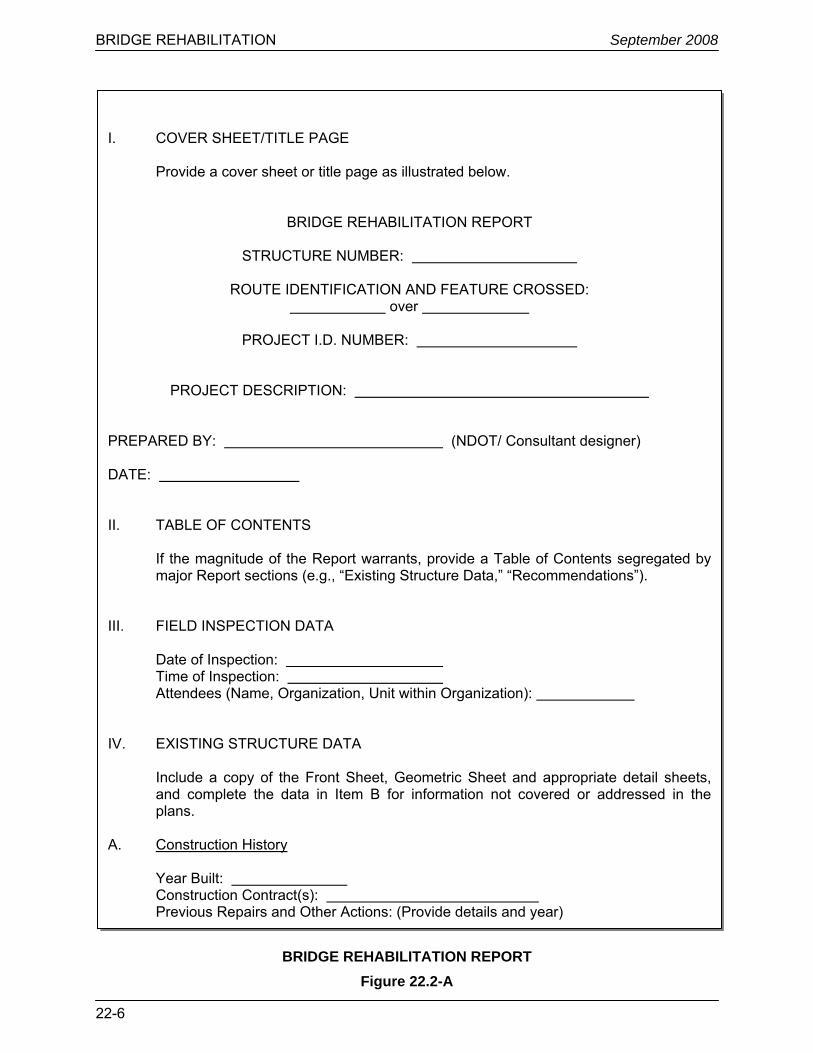
Figure 22.2-A presents the format and content of the Bridge Rehabilitation Report.
BRIDGE REHABILITATION September 2008
22-6
BRIDGE REHABILITATION REPORT
Figure 22.2-A
I. COVER SHEET/TITLE PAGE
Provide a cover sheet or title page as illustrated below.
BRIDGE REHABILITATION REPORT
STRUCTURE NUMBER:
ROUTE IDENTIFICATION AND FEATURE CROSSED: over
PROJECT I.D. NUMBER:
PROJECT DESCRIPTION: PREPARED BY: (NDOT/ Consultant designer) DATE: II. TABLE OF CONTENTS
If the magnitude of the Report warrants, provide a Table of Contents segregated by major Report sections (e.g., “Existing Structure Data,” “Recommendations”).
III. FIELD INSPECTION DATA
Date of Inspection: Time of Inspection: Attendees (Name, Organization, Unit within Organization): IV. EXISTING STRUCTURE DATA Include a copy of the Front Sheet, Geometric Sheet and appropriate detail sheets,
and complete the data in Item B for information not covered or addressed in the plans.
A. Construction History Year Built: Construction Contract(s): Previous Repairs and Other Actions: (Provide details and year)
BRIDGE REHABILITATION September 2008
22-7
BRIDGE REHABILITATION REPORT
Figure 22.2-A (Continued)
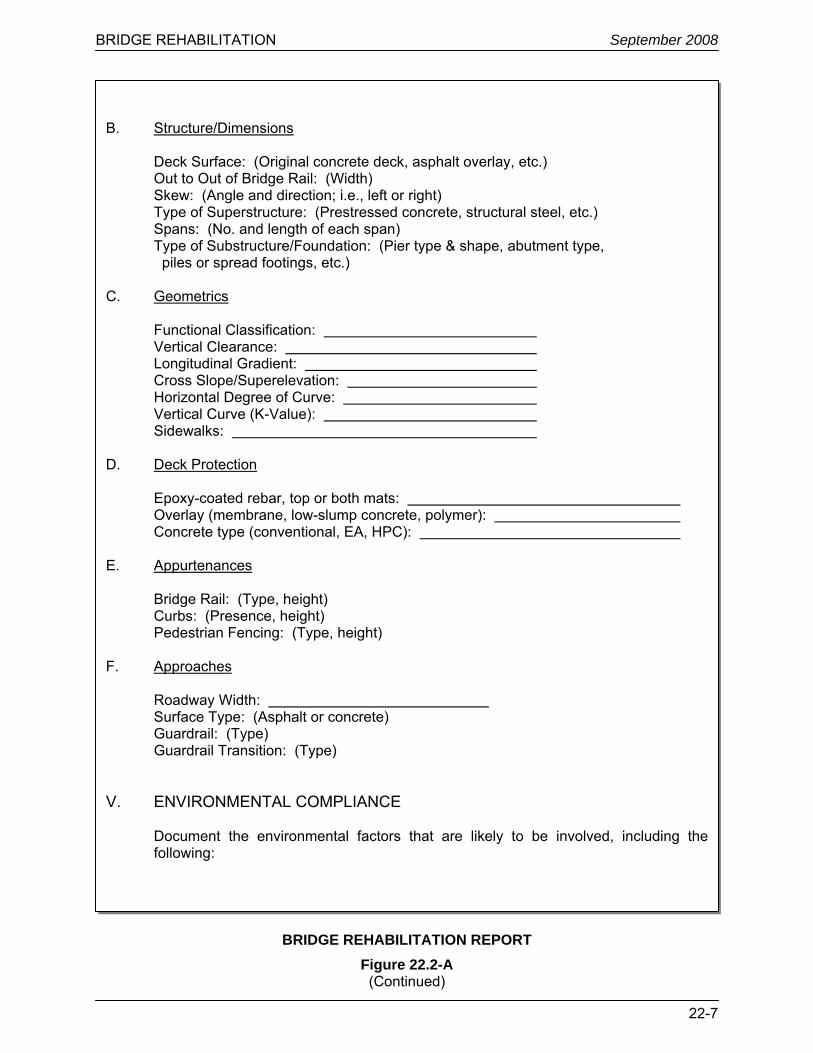
B. Structure/Dimensions Deck Surface: (Original concrete deck, asphalt overlay, etc.) Out to Out of Bridge Rail: (Width) Skew: (Angle and direction; i.e., left or right) Type of Superstructure: (Prestressed concrete, structural steel, etc.) Spans: (No. and length of each span) Type of Substructure/Foundation: (Pier type & shape, abutment type, piles or spread footings, etc.) C. Geometrics Functional Classification: Vertical Clearance: Longitudinal Gradient: Cross Slope/Superelevation: Horizontal Degree of Curve: Vertical Curve (K-Value): Sidewalks:
D. Deck Protection Epoxy-coated rebar, top or both mats: Overlay (membrane, low-slump concrete, polymer): Concrete type (conventional, EA, HPC): E. Appurtenances Bridge Rail: (Type, height) Curbs: (Presence, height) Pedestrian Fencing: (Type, height) F. Approaches
Roadway Width: Surface Type: (Asphalt or concrete) Guardrail: (Type) Guardrail Transition: (Type)
V. ENVIRONMENTAL COMPLIANCE
Document the environmental factors that are likely to be involved, including the following:
BRIDGE REHABILITATION September 2008
22-8
BRIDGE REHABILITATION REPORT Figure 22.2-A
(Continued)
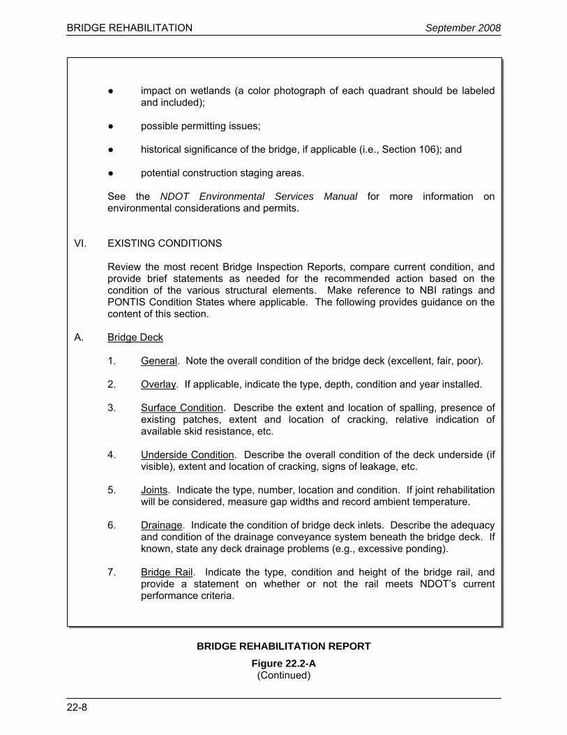
● impact on wetlands (a color photograph of each quadrant should be labeled and included);
● possible permitting issues;
● historical significance of the bridge, if applicable (i.e., Section 106); and ● potential construction staging areas. See the NDOT Environmental Services Manual for more information on environmental considerations and permits.
VI. EXISTING CONDITIONS
Review the most recent Bridge Inspection Reports, compare current condition, and provide brief statements as needed for the recommended action based on the condition of the various structural elements. Make reference to NBI ratings and PONTIS Condition States where applicable. The following provides guidance on the content of this section.
A. Bridge Deck
1. General. Note the overall condition of the bridge deck (excellent, fair, poor).
2. Overlay. If applicable, indicate the type, depth, condition and year installed.
3. Surface Condition. Describe the extent and location of spalling, presence of existing patches, extent and location of cracking, relative indication of available skid resistance, etc.
4. Underside Condition. Describe the overall condition of the deck underside (if
visible), extent and location of cracking, signs of leakage, etc. 5. Joints. Indicate the type, number, location and condition. If joint rehabilitation
will be considered, measure gap widths and record ambient temperature.
6. Drainage. Indicate the condition of bridge deck inlets. Describe the adequacy and condition of the drainage conveyance system beneath the bridge deck. If known, state any deck drainage problems (e.g., excessive ponding).
7. Bridge Rail. Indicate the type, condition and height of the bridge rail, and
provide a statement on whether or not the rail meets NDOT’s current performance criteria.
BRIDGE REHABILITATION September 2008
22-9
BRIDGE REHABILITATION REPORT Figure 22.2-A
(Continued)
8. Curbs/Sidewalks. If present, provide a statement on the overall condition. B. Superstructure
1. General. Note the overall condition of the superstructure (excellent, fair, poor).
2. Repair/Maintenance Work. If known or if visible, identify any prior repair and
maintenance work performed.
3. Specific Deficiencies. Where applicable, identify the extent and location of any specific structural deficiencies (e.g., cracking, spalling of concrete, rust on metal components, deformation, loss in concrete or metal components).
4. Fracture Critical Members and Low Fatigue Life Details. Identify any fracture
critical or fatigue-prone members. 5. Damage. Identify any damage due to collisions by vessels, vehicles, etc.
6. Bearings, Pedestals. State the functionality of these elements and indicate any deficiencies, including seismic compatibility.
C. Substructures/Foundations
1. General. Note the overall condition of the substructures and foundations and slope protection (excellent, fair, poor). Also indicate the substructure and foundation types and materials.
2. Repair/Maintenance. If known or if visible, identify any prior repair or
maintenance work performed (e.g., patching of concrete).
3. Specific Deficiencies. Where applicable, identify the extent and location of any specific structural deficiencies (e.g., cracking, leaching, deterioration, settlement, rotation, exposed reinforcement).
4. Drainage. Indicate overall adequacy of drainage with respect to the
substructure and foundation and note any problems (e.g., erosion).
D. Seismic Assessment. Research seismic prioritization rating and Seismic Zone. Indicate the structure’s apparent ability to meet current NDOT criteria for seismic load-carrying capacity based on the Seismic Zone (e.g., adequate or inadequate support length). Provide a preliminary assessment of potentially vulnerable elements and provide recommendation for further seismic retrofit study.
BRIDGE REHABILITATION September 2008
22-10
BRIDGE REHABILITATION REPORT Figure 22.2-A
(Continued)
E. Scour Assessment. Research scour assessment and provide recommendations for
mitigation. F. Approaches
1. General. Note the overall condition of the approaches (excellent, fair, poor).
2. Approach Slab/Pavement. Indicate the condition of the approach slabs, pavement relief joints and the approach pavement immediately adjacent to the bridge or approach slab.
3. Guardrail. For each quadrant, indicate the type, length(s) and condition of the
guardrail, guardrail transition (or the absence of one), and guardrail end treatment and provide a statement on whether or not the system meets current performance criteria.
4. Roadway Drainage. Indicate the location and condition of drainage structures
adjacent to the bridge or approach slabs. G. Slope Pavement. Note the overall condition and material of existing slope pavement
(excellent, fair, poor). H. Utilities. Identify all apparent existing utilities, attached to various structural elements,
and their locations (e.g., conduits, electrical boxes, gas lines, water lines). VII. RECOMMENDATIONS A. Condition Surveys and Tests
Section 22.4 identifies an array of condition surveys and tests. Indicate which of these, if any, should be undertaken before definitive rehabilitation recommendations are made.
B. Bridge Deck
Identify the proposed work to the bridge deck. Where applicable, document the following:
● patching (indicate approximate depth) or replacement of a portion or all of the existing bridge deck;
● the proposed bridge deck overlay in conjunction with deck patching;
BRIDGE REHABILITATION September 2008
22-11
BRIDGE REHABILITATION REPORT Figure 22.2-A
● removal, replacement and/or addition of curbs, pedestrian fencing, sidewalks
and/or medians; ● bridge expansion joint repair and/or replacement;
● drainage improvements; and
● upgrading or replacing bridge rails and/or guardrail-to-bridge-rail transitions. Section 22.5 identifies bridge deck rehabilitation techniques.
C. Superstructure
Identify the proposed work, if any, to the existing superstructure. Where applicable, document the following: ● removing, replacing, adding or strengthening structural members; ● patching concrete structural members;
● replacing or repairing bearing assemblies;
● cleaning and painting structural steel beams; and ● fatigue repair or upgrade.
Sections 22.6 and 22.7 identify rehabilitation techniques for concrete and steel superstructures.
D. Substructures/Foundations
Identify the proposed work, if any, to the existing substructure and foundation. Where applicable, document the following:
● repairing, adding or strengthening structural members;
● providing seismic retrofit measures (e.g., seat extensions, restrainers); ● repairing deteriorated concrete; ● implementing remedial actions for hydraulic scour; and ● constructing or repairing slope protection.
Section 22.8 identifies rehabilitation techniques for the substructure and foundation. See Section 22.9 for information on seismic retrofit rehabilitation techniques.
BRIDGE REHABILITATION September 2008
22-12
(Continued)
BRIDGE REHABILITATION REPORT Figure 22.2-A
(Continued)
E. Approaches
Identify the proposed work to the bridge approaches. Where applicable, document the following:
● repairs to or replacement of approach slabs and bridge rail; ● repairs to or replacement of pavement relief joints; and ● repairs to or replacement of bridge rail/guardrail connections.
F. Utilities
Identify any known utility adjustments necessitated by the bridge rehabilitation work. Contact the Utilities Section for more information on the utility.
G. Traffic Control During Construction
Identify the proposed strategy for maintaining traffic during construction and how it coincides with the proposed rehabilitation. This could include alternating one-way traffic with signals, using stage construction or diverting the traffic to a detour route.
VIII. PRELIMINARY COST ESTIMATE
Provide a preliminary cost estimate for the proposed bridge rehabilitation work. See Chapter 6.
IX. ECONOMIC COST COMPARISON
A major bridge rehabilitation should include a cost estimate for rehabilitation versus replacement.
X. SCHEMATICS
Provide schematics for the proposed bridge improvements. The schematics should indicate the following:
• width for: + travel lanes, + shoulders,
BRIDGE REHABILITATION September 2008
22-13
BRIDGE REHABILITATION REPORT
Figure 22.2-A (Continued)
+ clear roadway, + out-to-out of bridge rail, and + overhangs; • roadway cross slope; • height of curb; • sidewalk width; • bridge rail type and basic dimensions; and • girder type, depth and spacing. XI. PHOTOGRAPHS
Provide color photographs depicting in sufficient detail the overall condition of the structure and its elements. The pictures can then be used in reviewing and evaluating the existing condition and rehabilitation recommendations.
BRIDGE REHABILITATION September 2008
22-14
22.3 BRIDGE REHABILITATION LITERATURE
The design of new bridges is based primarily on the AASHTO LRFD Bridge Design Specifications. No national publication exists that, in a single document, presents accepted practices, policies, criteria, etc., for the rehabilitation of existing bridges as the LRFD Specifications provides for original design. However, the highway research community has devoted significant resources to identifying practical, cost-effective methods to rehabilitate existing highway bridges.
Publications are available that may be of special interest to the bridge designer when rehabilitating an existing bridge. The designer is encouraged to evaluate the research literature to identify publications that may be useful on a project-by-project basis. Visit the websites for FHWA, AASHTO, Transportation Research Board, etc., for more information. The bridge designer should also review the publications available in NDOT's research library.
BRIDGE REHABILITATION September 2008
22-15
22.4 BRIDGE CONDITION SURVEYS AND TESTS
Section 22.4 discusses NDOT policies and practices for condition surveys and tests for a bridge rehabilitation project. The discussion does not pertain to any condition surveys and tests performed for the Nevada Bridge Inspection Program (see Chapter 28) nor the NDOT Bridge Management System (see Chapter 29).
22.4.1 General
The bridge designer is responsible for:
• arranging and conducting field reviews; • requesting specific tests to be performed by others (e.g., chloride-content analysis); • evaluating data collected during the field survey and provided by others; • determining the appropriate scope of rehabilitation or if replacement is appropriate; and • preparing the contract documents. The decision on the type and extent of bridge rehabilitation is based on information acquired from condition surveys and tests. The selection of these condition surveys and tests for a proposed project is based on a case-by-case assessment of the specific bridge site. The bridge designer should request assistance from the Non-Destructive Testing Squad (see Chapter 26) and from the Materials Division. The Materials Division can offer support in the following areas:
• geotechnical evaluation/foundation recommendations, • concrete corings for cracking and/or strength assessment, • chloride sampling and testing, • corings to determine depth of surfacing materials, • slope stability analysis and recommendations, • evaluation of bond strength of overlay materials, and • skid testing. 22.4.2 Concrete Bridge Decks
22.4.2.1 General
For this Chapter, concrete bridge decks include the structural continuum directly supporting the riding surface, expansion joints, curbs, barriers, approach slabs and utility hardware (if suspended from the deck). Concrete bridge decks include decks supported on girders and the top slabs of cast-in-place box girders. The bridge deck and its appurtenances provide the following functions:
• support and distribution of wheel loads to the primary structural components;
• protection of the structural components beneath the deck;
• provide a smooth riding surface; and
• a safe passageway for vehicular and bicycle/pedestrian traffic (e.g., skid-resistant surface, bridge rails, guardrail-to-bridge-rail transitions).
BRIDGE REHABILITATION September 2008
22-16
Any deterioration in these functions warrants investigation and possible remedial action. A bridge deck has a finite service life, which is a function of both adverse and beneficial environmental factors. The most common cause of concrete bridge deck deterioration is the intrusion of chloride ions from roadway deicing agents into the concrete. The chloride causes formation of corrosive cells on the steel reinforcement, and the corrosion product (rust) induces stresses in the concrete resulting in cracking, delamination and spalling. Chloride ion (salt) penetration is a time-dependent phenomenon. There is no known way to prevent penetration, but it can be decelerated such that the service life of the deck is not less than that of the remaining structure. Chloride penetration is, however, not the only cause of bridge deck deterioration. Other significant problems include:
1. Freeze-Thaw. Results from inadequate air content of the concrete. Freezing of the free water in the concrete causes random, alligator cracking of the concrete and then complete disintegration. There is no known remedy other than replacement.
2. Impact Loading. Results from vehicular kinetic energy released by vertical discontinuities in the riding surface, such as surface roughness, delamination and inadequately set or damaged expansion joints. Remedial actions are surface grinding, overlay or replacement of deck concrete and rebuilding expansion joints.
3. Abrasion. Normally results from metallic objects, such as chains or studs attached to tires. Remedial actions are surface grinding or overlay.
Certain factors are symptomatic indicators that a bridge deck may have a shorter than expected service life and that it is actually in the latter phases of its service life. Some examples are:
• extensive cracking (shrinkage, stress, etc); • extensive delamination; • exposed reinforcing steel; and • spalls. The deck can be placed into one of the following categories (based on NBI ratings):
1. Very good decks that need little attention. These are the (8) and (9) rated decks.
2. Decks that are in reasonably good shape and need no substantial repair, but their lives can be extended with a nominal maintenance expenditure. These are the (7) rated decks. Decks in this condition range would most likely need some minor crack sealing and minor patching.
3. Decks that need considerable repair but are still quite sound and capable of serving adequately for five to ten more years. These are candidates for repair and overlay with some type of non-permeable concrete. These are the (5) and (6) rated decks. The designer would most likely consider an overlay for bridge decks in this condition range, depending on the extent of chloride contamination.
4. Decks that are no longer serviceable and will soon need replacement regardless of any remedial action. Significant expenditures of funds are not justified until replacement. However, minor maintenance expenditures could extend the remaining life several years. These are the (3) and (4) rated decks. Decks in these conditions fall into the “replace deck” category.
When considering a bridge for rehabilitation, the Structures Division requests a number of tests to collect data on the deck’s condition. The data allows the designer to determine whether deck
BRIDGE REHABILITATION September 2008
22-17
rehabilitation or deck replacement is appropriate and, if the choice is rehabilitation, the information allows the determination of the appropriate level of treatment.
The following information may be collected during a deck evaluation:
• a plot locating existing delaminations, spalls and cracks;
• representative measurements of crack width;
• measurements of the depth of cover on the top mat of reinforcing steel;
• sampling and laboratory analysis to determine the existing levels of chloride contamination;
• measurements of electrical potential on a grid pattern to locate areas of active corrosion; and
• deck concrete compressive strength assessed through destructive testing of deck core samples.
Expect to obtain at least some degree of confirmation and conflicting test results because these field tests each have a degree of uncertainty. Thus, sampling multiple locations within a traffic lane is important to estimate the true condition of the deck and the extent of active corrosion. Engineering judgment must be applied when analyzing multiple test results. The following provides more information on each type of data collected and their use in determining an appropriate deck treatment.
22.4.2.2 Visual Inspection
Description: A visual inspection of the bridge deck should establish: • the approximate extent of cracking, representative crack widths and spalling; • evidence of any corrosion; • evidence of pattern cracking, efflorescence or dampness on the deck underside; • rutting of the riding surface and/or ponding of water; • operation of expansion joints; • functionality of deck drainage system; and • bridge rails and guardrail-to-bridge-rail transitions meeting current NDOT standards. Purpose: The visual inspection of the bridge deck will achieve the following: • By establishing the approximate extent of cracking and crack width, corrosion,
delamination and spalling (and by having evidence of other deterioration), the designer can determine if a more extensive inspection is warranted.
• The inspection will identify substandard roadside safety appurtenances.
When to Use: All potential deck rehabilitation projects.
Analysis of Data: Pattern cracking, heavy efflorescence or dampness on the deck underside suggests that this portion of the deck is likely to be highly contaminated and active corrosion is taking place. In addition, the designer should consider:
BRIDGE REHABILITATION September 2008
22-18
• traffic control; • timing of repair; • age of structure; • average annual daily traffic (AADT); • slab depth; • structure type; • depth of cover to reinforcement; and • crash history (e.g., wet weather). 22.4.2.3 Delamination Sounding
Description: Establishes the presence of delamination, based on audible observation, by chain drag or hammer. Based on the observation that delaminated concrete responds with a “hollow sound” when struck by a metal object. See ASTM D4580 Standard Practice for Measuring Delaminations in Concrete Bridge Decks by Sounding.
Purpose: To determine the location and area of delamination.
When to Use: On all concrete deck rehabilitation projects, except where asphalt overlays prevent performance of the test.
Analysis of Data: Based on the extent of the bridge deck spalling, the following will apply:
• 10% delamination of surface area is a rough guide for considering remedial action. • 40% delamination is a rough guide for considering bridge deck replacement. 22.4.2.4 Chloride Analysis
Description: A chemical analysis of pulverized samples of concrete extracted from the bridge deck. Concentrations of water-soluble chlorides are determined using the Gravimetric Method ⎯ Silver Chloride Method as described in Scott’s Standard Methods of Chemical Analysis, 6th Edition, March 1962, (D. Van Nostrand). As an option, chloride testing by others for NDOT may be conducted using potentiometric titration with silver nitrate per AASHTO T 260 Sampling and Testing for Chloride Ion in Concrete and Concrete Raw Materials.
Purpose: To determine the chloride content profile from the deck surface to a depth of approximately 3 in or more.
When to Use: Use on bridge decks where the need for major rehabilitation or replacement is anticipated. Take chloride samples at three to five locations along the travel lane per span from each span 100 ft or less in length. Increase the number of samples for longer spans.
Analysis of Data: The “threshold” or minimum level of water-soluble chloride contamination in concrete necessary to corrode reinforcing steel is approximately 1.3 to 2.0 lbs/yd3. Chloride concentrations of less than this threshold indicate a sound deck that will in most cases not require rehabilitation. Consideration may be given to adding a deck protection system. Chloride concentrations within or greater than this range above the top reinforcing mat require the removal of at least enough concrete so that the remaining concrete contamination is below the threshold.
BRIDGE REHABILITATION September 2008
22-19
Threshold or greater chloride concentrations at the level of the top reinforcing mat require either 1) demolition to remove enough concrete to ensure that the remaining concrete is below the threshold values, or 2) possibly deck replacement. Threshold contamination or worse at or near the level of the bottom mat of reinforcing steel may require deck replacement
22.4.2.5 Pachometer Readings
Description: The pachometer produces a magnetic field in the bridge deck. A disruption in the magnetic field, such as induced by a steel reinforcing bar, is displayed.
Purpose: To determine the location and depth of steel reinforcing bars. These properties can be established to a depth of approximately 4 in.
When to Use: Pachometer readings are used on all concrete rehabilitation projects to verify reinforcement location as needed. They are often used to locate steel to avoid damage when drilling or coring concrete.
22.4.2.6 Ground-Penetrating Radar (GPR)
Description: Ground-coupled or air-coupled radar antennas emit very short, precisely timed pulses of radio-frequency electromagnetic energy into the bridge deck. When the pulses transition from either one material to another, or across areas of the same material having different dielectric properties (such as from an area of sound concrete into a deteriorated area), part of the energy is reflected back to a receiver positioned at the surface, and varying amounts of energy are absorbed or diffracted within the material. Deteriorated materials absorb/refract more energy than sound materials. Computer software analyzes variations in the return strength versus absorption of this pulse-echo and the length of time required for the echo to return to the antenna. The program will generate condition reports.
Purpose: When the GPR system is used to survey a concrete bridge deck, the following information can be obtained:
• apparent location and depth of unsound concrete (subject to ground-truth verification), • depth of the reinforcing steel, and • thickness of the bridge deck and overlay materials. This information is used to supplement other inspection methods to locate sections of a bridge deck in need of repair.
When to Use: Asphalt-overlayed bridge decks are excellent candidates for GPR investigation, as are decks constructed using stay-in-place formwork. GPR should be considered where traffic must be maintained during testing. Because vehicle-mounted antennas can be effective at low to moderate speeds, the need for lane closures may possibly be avoided. The test is nondestructive; therefore, there is no follow-up repair work.
22.4.2.7 Half-Cell Method
Description: Copper/copper sulphate half-cell method for the measurement of electrical potential as an indicator of corrosive chemical activity in the concrete. See ASTM C876 “Test Method for Half-Cell Potentials of Uncoated Reinforcing Steel in Concrete.”
BRIDGE REHABILITATION September 2008
22-20
Purpose: To determine the level of active corrosion in the bridge deck.
When to Use: This test method is not often used by NDOT. Even if a concrete deck has a wearing surface, half-cell readings can be made after areas of the deck are exposed.
Analysis of Data: A voltage potential difference of -0.35 volts or less indicates active corrosion; more recent work suggests that -0.23 volts is the threshold of corrosion. Less negative readings indicate more active corrosion, while higher negative (smaller in absolute value) readings indicate lower corrosion.
22.4.2.8 Coring
Description: 2-in or 4-in diameter cylindrical cores are taken. In decks with large amounts of reinforcement, it is difficult to avoid cutting steel if 4-in diameter cores are used.
Purpose: To establish strength, composition of concrete, crack depth, position of reinforcing steel.
When to Use: On all concrete deck rehabilitation projects when doubt exists on the compressive strength or soundness of the concrete or if the visual condition of the reinforcement is desired.
Analysis of Data: Less than 2 in of concrete cover is considered inadequate for corrosion protection. If compressive strengths are less than 3 ksi, the designer must determine whether to proceed with the deck rehabilitation or to proceed with a deck replacement.
22.4.2.9 Testing for Alkali-Silica Reactivity (ASR)
Alkali-silica reactivity is the process in which an expanding gel is produced by the breakdown of certain minerals (mostly glass-type silica) in the presence of moisture within the highly alkaline concrete environment. The expanding gel induces tensile forces in the concrete matrix causing cracking of the concrete. This cracking allows free water to infiltrate into the concrete creating more gel and, subsequently, more expansion. Ultimately, the concrete fails or disintegrates.
Test procedures for ASR are tabulated below.
Test Purpose Description
ASTM C856, petrographic examination of hardened concrete
Outlines petrographic examination procedures for hardened concrete; useful in determining condition or performance
Short-term visual (unmagnified) and microscopic examination of prepared samples
ASTM C856 (AASHTO T299), annex uranyl-acetate treatment procedure
Identifies products of ASR in hardened concrete
Staining of a freshly exposed concrete surface and immediate viewing under UV light
Los Alamos staining method Identifies products of ASR in hardened concrete
Staining of a freshly-exposed concrete surface with two different reagents
BRIDGE REHABILITATION September 2008
22-21
The ASTM C856 annex uranyl-acetate treatment procedure and the Los Alamos staining method identify small amounts of ASR gel whether they cause expansion or not. These tests should be supplemented by the ASTM C856 petrographic examination, or physical tests, for determining concrete expansion.
22.4.3 Superstructure
As defined in this Manual, the superstructure consists of the bearings and all of the components and elements resting upon them. See Section 22.4.2 for condition assessments and surveys on bridge decks. The following briefly describes those condition surveys and tests that may be performed on the superstructure elements to determine the appropriate level of rehabilitation.
22.4.3.1 Visual Inspection
Description: A visual inspection of the superstructure should include an investigation of the following to supplement the information contained in the NBI Bridge Inspection Report:
• surface deterioration, cracking and spalling of concrete; • major loss in concrete components; • evidence of efflorescence; • corrosion of reinforcing steel or prestressing tendons; • loss in exposed reinforcing steel or prestressing tendons; • pealing and delaminating coating system; • corrosion of structural metal components; • loss in metal components due to corrosion; • cracking in metal components; • excessive deformation in components; • loosening and loss of rivets or bolts; • deterioration and loss in wood components; • damage due to collision by vehicles, vessels or debris; • leakage through expansion joints; • ponding of water on abutment seats; • state and functionality of bearings; and • distress in pedestals and bearing seats. Purpose: To record all deterioration and signs of potential distress for comparison with earlier records and for initiating rehabilitation procedures if warranted.
When to Use: On all bridge rehabilitation projects.
Analysis of Data: As required, if the deterioration is deemed significant enough to result in loss of load-carrying capacity.
22.4.3.2 Ground-Penetrating Radar (Concrete)
See Section 22.4.2.6.
BRIDGE REHABILITATION September 2008
22-22
22.4.3.3 Testing for Alkali-Silica Reactivity (ASR) (Concrete)
See Section 22.4.2.9.
22.4.3.4 Fracture-Critical Members (Steel)
A fracture-critical member is a metal structural component, typically a superstructure tension or bending member that would cause collapse of the structure or span if it fails. Fracture-critical structures in Nevada have been identified and catalogued; contact the Assistant Chief Structures Engineer – Inventory/Inspection. The designer must recognize typical fracture-critical details when conducting the field review because it may affect the scope of bridge rehabilitation. Typical bridges in Nevada containing fracture-critical members are:
• steel trusses (pins, eye-bars, bottom chords and other tension members); • two-girder steel bridges; • transverse girders (supporting longitudinal beams and girders); and • pin-and-hanger connections (located on suspended spans or at transverse girders). 22.4.3.5 Load-Induced Fatigue Analysis (Steel)
Description: Fatigue is defined as steady-state crack growth. Failure of the component can result from growth of existing flaws in steel members to a critical size at which fracture is no longer effectively resisted by the toughness of the steel. The crack growth is a function of:
• crack size; • location of crack (i.e., stress concentration at the structural detail); • toughness (energy-absorbing characteristics of metal); • temperature; and • frequency and level of nominal stress range (transient stresses). Purpose: To establish type and urgency of remedial action.
When to Use: Where cracks, found by visual inspection, are believed to be caused by fatigue or at fatigue-prone details.
Analysis of Data: Analysis should be performed by a structural engineer who is experienced in fatigue-life assessment. For the analysis, fatigue characteristics of the metal should be established. For the stress range, the LRFD Specifications provides an upper-bound criterion of 75% weight of one design truck plus impact per bridge. The actual stress range of a given bridge component may be far lower than that specified by the LRFD Specifications, and it may be warranted to establish it by physical means. See Section 15.4 for further discussion. The following discussion illustrates how to calculate the stress cycles for existing bridges not satisfying the infinite-life check.
* * * * * * * * * *
For existing bridges not satisfying the infinite fatigue life check, LRFD Article 6.6.1.2.5 shall be used to define the total number of stress cycles (N) as:
N = (365)(75)n(ADTT)SL (LRFD Eq. 6.6.1.2.5-2)
Where:
BRIDGE REHABILITATION September 2008
22-23
n = number of stress range cycles per truck passage. As defined in LRFD Article 6.6.1.2.5, for simple and continuous spans not exceeding 40 ft, n = 2.0. For spans greater than 40 ft, n = 1.0, except at locations within 0.1 of the span length from a continuous support, where n = 1.5.
ADTT = the number of trucks per day in one direction averaged over the design life of the structure.
ADTTSL = Average Daily Truck Traffic in a single lane = (p)(ADTT), which is LRFD Equation 3.6.1.4.2-1.
p = the fraction of truck traffic in a single lane. As defined in LRFD Article 3.6.1.4.2, when one direction of traffic is restricted to:
• 1 lane: p = 1.00 • 2 lanes: p = 0.85 • 3 or more lanes: p = 0.80
The portion of LRFD Equation 6.6.1.2.5-2 that is (365)(75)(ADTT)SL represents the total accumulated number of truck passages in a single lane during the 75-year design life of the structure. If site-specific values for the fraction of truck traffic data are unavailable from the NDOT Traffic Information Services, the values provided in LRFD Table C3.6.1.4.2-1 may be used.
Example 22.4-1
Given: Total number of truck passages in a single lane during the 75-year design life (from NDOT Traffic Information Services) = 9.75 x 10⁶
Two spans, 160 ft each
Longitudinal connection plate located 30 ft from the interior support
Unfactored DL stress at the toe of the connection plate-to-web weld = 4 ksi compression
Unfactored fatigue stresses at the toe of the connection plate-to-web weld using unmodified single-lane distribution factor = 3.9 ksi tension and 4.5 ksi compression
Find: Determine the fatigue adequacy at the toe of a longitudinal connection plate-to-web weld with a transition radius of 4 in with the end welds ground smooth.
Solution:
Step 1: The LRFD Specifications classifies this connection as Detail Category D. Therefore:
• A = Detail Category Constant = 22.0 x 10⁸ ksi3 (LRFD Table 6.6.1.2.5-1)
• (ΔF)TH = Constant Amplitude Fatigue Threshold = 7.0 ksi (LRFD Table 6.6.1.2.5-3)
Step 2: Compute the factored live-load fatigue stresses by applying dynamic load allowance and fatigue load factor and removing the multiple presence factor:
BRIDGE REHABILITATION September 2008
22-24
Tension: 3.9(1.15)(0.75)/1.2 = 2.8 ksi Compression: 4.5(1.15)(0.75)/1.2 = 3.2 ksi Fatigue Stress Range: = 6.0 ksi
Step 3: Determine if fatigue must be evaluated at this location:
• Net tension = (DL stress) – (Fatigue stress) • Net tension = 4 ksi (Compressive) – 3.9 ksi (Tensile) = 0.1 ksi (Compressive)
Although there is no net tension in the web at the location of the longitudinal connection plate, the unfactored compressive DL stress (4 ksi) does not exceed twice the tensile fatigue stress (5.6 ksi). Therefore, fatigue must be considered.
Step 4: Check for infinite life:
First, check the infinite life term. This will frequently control the fatigue resistance when traffic volumes are large. (ΔF)n = ½(ΔF)TH = 0.5(7.0) = 3.5 ksi. Because the fatigue stress range (6.0 ksi) exceeds the infinite life resistance (3.5 ksi), the detail does not have infinite fatigue life.
Step 5: Determine “n” for LRFD Equation 6.6.1.2.5-2:
The span exceeds 40 ft and the point being considered is located more than 0.1 of the span length away from the interior support. Therefore, n = 1.0.
Step 6: Using LRFD Equation 6.6.1.2.5-2, compute the number of stress cycles:
N = (9.75 x 10⁶)(n) N = (9.75 x 10⁶)(1.0) N = 9.75 x 10⁶
Step 7: Using LRFD Equation 6.6.1.2.5-1, compute the nominal fatigue resistance:
Nominal Fatigue Resistance
75-Year Life Resistance
Infinite Life Resistance
(ΔF)n = (A/N)1/3 ≥ ½(ΔF)TH
Step 8: Check to see if the detail will have at least a 75-year fatigue life:
(ΔF)n = (A/N)1/3
= [(22.0 x 10⁸)/(9.75 x 106)]1/3 = 6.1 ksi
The 75-year factored fatigue resistance (6.1 ksi) exceeds the fatigue stress range (6.0 ksi); therefore, the detail is satisfactory.
* * * * * * * * * 22.4.4 Substructures
As discussed in Chapter 18, substructure elements include piers and abutments. For the purpose of Chapter 22, substructures also include foundations, which are discussed in Chapter
BRIDGE REHABILITATION September 2008
22-25
17. The following briefly describes those condition surveys and tests that may be performed on these elements to determine the appropriate level of rehabilitation.
22.4.4.1 Visual Inspection
Description: A visual inspection of the substructure components should address the following to supplement the NBI Bridge Inspection Report:
• surface deterioration, cracking and spalling of concrete; • major loss in concrete components; • evidence of corrosion in reinforcing steel; • loss in exposed reinforcing steel; • deterioration or loss of integrity in wood components; • leakage through joints and cracks; • dysfunctional drainage facilities; • collision damage; • changes in geometry such as settlement, rotation of wingwalls, tilt of retaining walls, etc; • seismic vulnerabilities; • accumulation of debris; • erosion of protective covers; • changes in embankment and water channel; and • evidence of significant scour.
Purpose: To record all deterioration and signs of potential distress for comparison with earlier records and for initiating rehabilitation procedures if warranted.
When to Use: On all potential bridge rehabilitation projects.
Analysis of Data: As required, if the deterioration is deemed significant enough to result in loss of load-carrying capacity.
22.4.4.2 Ground-Penetrating Radar
See Section 22.4.2.6.
22.4.4.3 Testing for Alkali-Silica Reactivity (ASR)
See Section 22.4.2.9.
22.4.5 Summary
The bridge condition surveys, test, analyses and reports will indicate the extent of the problems and the objectives of rehabilitation. Sections 22.5 through 22.9 present specific bridge rehabilitation techniques that the designer may employ to address the identified deficiencies. These Sections are segregated by structural element (i.e., bridge decks, steel superstructures, concrete superstructures, substructures and seismic retrofit).
BRIDGE REHABILITATION September 2008
22-26
22.5 BRIDGE DECK REHABILITATION
22.5.1 General
Chapter 16 provides an in-depth discussion on the design of bridge decks that are constructed compositely in conjunction with concrete and steel girders and as part of cast-in-place, post-tensioned box girders for new bridges. Many of the design and detailing practices provided in the Chapter may also apply to deck rehabilitation. Therefore, the designer should review Chapter 16 to determine its potential application to a bridge deck rehabilitation project.
22.5.2 Typical NDOT Practices
The following discusses typical NDOT practices for bridge deck rehabilitation.
22.5.2.1 Bridge Deck Overlay
The following identifies typical NDOT practices on bridge deck overlays:
1. Patching. Patching the bridge deck with a fast-setting concrete should be considered a temporary measure to provide a reasonably acceptable riding surface until a more permanent solution can be applied. The longevity of patches is highly dependent upon the deck preparation, patching materials and location of the patch. Avoid patching with asphalt.
2. Polymer Concrete Overlays. Polymer concrete overlays have been in use in Nevada since the early 1990s. They have a good performance history. Contrary to cement-based overlays, the construction of a polymer concrete overlay is enhanced in a dry climate. In general, polymer concrete is preferred over other overlay materials.
3. Resin Overlays. Thin resin overlays have been occasionally used in Nevada since the early 2000s. They have a fair to good performance history. The thin resin overlay is used for bridge deck protection and to restore skid resistance.
4. Asphalt Overlay with Sheet Membrane. This method was used in the 1960s and early 1970s with limited success. The difficult construction tolerances for surface preparation, membrane discontinuities and application temperature have resulted in poor results. However, it is still used occasionally on certain bridges such as side-by-side boxes where reflective cracking through a concrete or polymer overlay is a concern.
A damaged waterproofing system is counterproductive in that it retains salt-laden water and continues supplying it to the deck which, thus, never dries out. Also, rain water or washing efforts cannot remove the salt.
5. Replacement Overlay. It is acceptable to remove an existing overlay and replace it with a new one. NDOT policy is to not allow a new overlay to be placed over an existing bridge deck overlay, because it is counterproductive and adds to the dead load of the structure.
BRIDGE REHABILITATION September 2008
22-27
22.5.2.2 Expansion Joints
The service life of bridge deck expansion joints is much shorter than that of the bridge, and leaking and faulty joints represent a hazard for the deck and the main structural components. Where applicable, the bridge deck rehabilitation should be consistent with the criteria described in Chapter 19 relative to the design of bridge deck expansion joints. Chapter 19 identifies the following types of expansion joints that are typically used to retrofit an existing bridge:
• strip seal, • preformed joint filler, • asphaltic plug, or • pourable seals. 22.5.3 Rehabilitation Techniques
The remainder of Section 22.5 presents a brief discussion on bridge deck rehabilitation techniques that may be considered:
• Patching • Polymer Concrete Overlay • Resin Overlay • Waterproof Membrane/Asphalt Overlay • Epoxy-Resin Injection • Crack Sealant • Silane Seal • Joint Rehabilitation • Joint Replacement • Upgrade/Retrofit Bridge Rails • Approach Slabs 22.5.3.1 Patching
A permanent repair can be assured only if all concrete in areas having a chloride content sufficient to sustain corrosion are removed. For partial depth repairs, concrete should be removed to a depth of ¼ in plus the maximum size of the aggregate below the bottom of the top mat of reinforcing steel. The actual corrosion threshold can be as low as 1.3 lb of Cl per cubic yard of a typical deck concrete, but a value of 2 lb of Cl per cubic yard is commonly accepted as the level beyond which removal of the concrete is warranted. Unless the contaminated concrete is removed, differences in the surface conditions on the reinforcing bar may cause the formation of anodic and cathodic areas and a resumption of the corrosion process. However, removal of concrete below the reinforcing steel may be extremely costly, and complete removal and replacement of the deck may be more economical. Patching of the deck followed by the installation of a protective overlay is a less costly and often used alternative.
An evaluation of the corrosion process indicates that patches cannot be considered permanent repairs, and field experience tends to verify this conclusion. Newly delaminated areas are often found adjacent to areas patched months before. Nevertheless, patching can be an appropriate temporary action until more extensive restoration is performed, and it can provide substantial service with the subsequent installation of a protective overlay.
BRIDGE REHABILITATION September 2008
22-28
The area to be patched can be defined in the deck by sounding and GPR. The concrete is then removed using pneumatic hammers with a maximum mass of 35 pounds. Surface preparation is critical. Roughen the exposed surface to ¼ in amplitude and avoid feathered edges. Any exposed reinforcing steel is cleaned. A bonding agent is applied to the existing concrete surface, when required, and the repair material is placed and cured.
A wide variety of materials has been used for patching bridge decks. Although conventional Portland cement concrete is often used, many other materials have been developed to provide rapid strength development and to allow early opening of the deck to traffic. It is essential that the manufacturer’s requirements for mixing, placing and curing be rigidly followed. If a polymer concrete overlay is proposed, it can also be used as the deck patching material.
Bonding components vary with the repair materials. Usually a bonding epoxy is brushed into the clean, sound surface of the underlying concrete prior to placement of a cement-based patch. Some prepackaged polymer-modified concretes develop sufficient adherence so that a bonding agent is not required. Consult the manufacturers of all prepackaged fast-setting patching materials for the proper bonding agents. A methacrylate primer is used for polymer overlay patches.
22.5.3.2 Polymer Concrete Overlay
Polymer concrete is a combination of a polymer resin (polyester/styrene) and well-graded durable aggregates. Unlike concrete overlays, polymer overlays provide a waterproof barrier. Its normal thickness is ¾ in but can be placed as thin as ½ in and has been placed as thick as 4 in. A methacrylate primer is needed to keep the polyester/styrene resin from being in contact with the alkaline concrete deck. The methacrylate primer also has the benefit of sealing any cracks in the deck.
The polymer concrete overlay has a set time of less than 2 hours. Traffic can be placed on the overlay usually on the same day of construction. Surface preparation includes shotblast removal of the top paste of concrete to ensure a bond between the deck and overlay.
22.5.3.3 Resin Overlay
Resin overlays consist of 1 to 3 layers of resin and fine aggregate. A special resin is spread on the deck with fine aggregate broadcast on top. Once the resin sets, this operation is repeated until the system is complete. Resin overlays provide a waterproof barrier.
Resin overlays set and cure quickly, and traffic can be placed on the overlay usually on the same day as application. Resin overlays are thin (i.e., approximately ⅜ in). Tapering of the approach roadway is not usually required with resin overlays.
22.5.3.4 Waterproof Membrane/Asphalt Overlay
NDOT does not normally use waterproof membranes with an asphalt overlay. It is impossible to inspect a bridge deck covered with asphalt. The overlay adds dead load to the bridge, which can reduce live-load capacity and the overlay traps moisture in the concrete further aggravating corrosion of the slab reinforcing. However, on certain bridges such as side-by-side box beams, a waterproof membrane with asphalt overlay has demonstrated better performance than concrete or polymer overlays. The concrete and polymer overlays have developed cracking at the joints between the box beams due to the differential movement of the boxes.
BRIDGE REHABILITATION September 2008
22-29
A waterproof membrane with asphalt overlay has comparable construction time frames as the other overlay systems. The surface preparation for the membrane is minimal. Only high points or exposed rocks must be removed so that they will not puncture the membrane. Traffic should never be allowed on the exposed membrane.
22.5.3.5 Epoxy-Resin Injection
Epoxy-resin injection is commonly used to fill cracks in decks. Because the resin is injected under pressure, it is usually possible to fill the entire depth of crack. Reinforcing bars are located with a Pachometer, and holes are drilled to an appropriate depth into the cracks between reinforcing bars. The crack between the injection ports is sealed with a putty-like epoxy applied to the concrete surface by hand. Injection ports are placed at the holes, and a suitable epoxy system capable of bonding to wet surfaces is injected into the entry hole under pressure until it appears in the exit hole(s). A pumping system, in which the two components of the epoxy are mixed at the injection nozzle, is usually employed.
22.5.3.6 Crack Sealant
A low-viscosity organic liquid compound is flooded over the deck, and fills the cracks by gravity and capillary action. Accordingly, the success of this operation depends on the crack size, selection of the appropriate compound, temperature, contamination on the crack walls and the skill of the operator. The deck surface must be cleaned prior to application of the sealant. This includes power sweeping the entire surface and blowing all loose material from the cracks using high pressure air. All traces of asphalt and petroleum products must be removed by sand blasting. Care is needed to not damage the existing concrete surface.
22.5.3.7 Silane Seal
One method of slowing the entry of chloride ions into the concrete is by sealing its surface with a penetrating silane sealer. Penetrating silane sealers have a service life of from 3 to 5 years but are a low-cost preventive maintenance alternative for sound decks. The entire surface is treated and is applied as recommended by the manufacturer. The method of surface preparation is the same as for the Crack Sealant.
22.5.3.8 Joint Rehabilitation and Replacement
Joint rehabilitation refers to the repair of a portion of an existing joint and not its complete replacement. Joint rehabilitation includes repairing or replacing loose or broken restrainers on strip seal expansion joints, failed header materials adjacent to joints or torn seals. In most cases, the failure is due to vehicle impact. Failure may also be due to incompressibles in the joint.
Broken concrete adjacent to the joint should be removed with hand-operated equipment limited in size to approximately 15 lbs. If the size of the broken concrete is large, dowelled reinforcement should be added to hold the repair together. Quick-set concrete or polymer concrete can be considered for patching material; a material compatible with the existing header material should be used. The concrete should be saw cut outside the limits of the broken concrete to an approximate depth of 1 in. Adjust the depth of saw cut to avoid damaging the reinforcing steel. All corners of the patch must be square.
BRIDGE REHABILITATION September 2008
22-30
Bridges with asphalt overlays require a concrete header adjacent to the expansion joint unless an asphaltic plug joint is used. Concrete headers should be at least 8 in wide but preferably 12 in. Deck concrete should be removed down to a distance below the top mat of reinforcing steel to provide development length for the new header reinforcement.
Use a minimum number of joint splices with a full-length seal preferred. Torn strip seals can be repaired by vulcanizing or gluing. However, vulcanizing is preferred.
Where joint rehabilitation is not feasible, a replacement of an existing damaged or malfunctioning joint may be necessary.
Chapter 19 provides guidance on joint selection.
22.5.3.9 Upgrade/Retrofit Bridge Rails
Section 16.5.1 presents NDOT practices for new bridge rails, which is based on NCHRP 350. Desirably, existing bridge rails on a bridge rehabilitation project will meet the criteria in Section 16.5.1 or will be replaced with a new, NCHRP-350 compliant bridge rail. However, this is not always practical for a variety of reasons (e.g., dead load considerations, incompatibility with an existing bridge deck). Therefore, the following presents NDOT policy on upgrading existing bridge rails:
1. Crash History. Review the crash history and the maintenance and repair history of the bridge rail.
2. Critical Design Details. Inspect the existing bridge rail to verify the integrity of critical design details, such as:
• base plate connections, • anchor bolts, • welding details, • concrete cracking, and • reinforcement development.
3. Safety Deficiencies. Even in the absence of an adverse crash history, an inspection of the existing bridge rail may reveal inherent safety deficiencies in the rail design, such as:
• potential for snagging (i.e., no blockouts); • presence of curb in front of bridge rail; • inadequate height; and/or • inadequate guardrail-to-bridge-rail transition.
Ultimately, any retrofit to an existing bridge rail, intended to improve the rail to an acceptable performance level, will be made on a case-by-case basis. The following describes three basic conceptual approaches for a retrofit:
1. Guardrail Retrofit. A relatively inexpensive retrofit is to install an approaching roadside barrier that meets the NCHRP 350 criteria and to continue the longitudinal member of the guardrail across the existing bridge rail to provide rail continuity. This retrofit can significantly improve the impact performance of a substandard bridge rail. Extending guardrail across a bridge is limited to short-span bridges only.

BRIDGE REHABILITATION September 2008
22-31
2. Concrete Retrofit of Steel Rails. A concrete barrier, either an F-shape or vertical wall, can sometimes be added to an existing substandard bridge rail. However, this retrofit is only feasible if the existing bridge can accommodate the additional dead load and if the existing curb and railing configuration can meet the anchorage requirements of the retrofitted barrier.
3. Concrete Retrofit of Concrete Rails. An F-shape or vertical wall can be used to replace an existing concrete bridge rail not meeting the height or strength requirements. A partial or complete removal of the existing rail is required depending upon the amount of existing reinforcing steel, its development and the condition of the existing concrete. The challenge of most retrofits is the additional strength requirements needed to meet the requirements of Section 16.5.1. In most cases, additional reinforcement is required, but there is a limited amount of deck thickness to develop the reinforcement. The width of the rail can be increased, but an evaluation of the existing deck/superstructure may be required to accommodate the additional dead load.
22.5.3.10 Approach Slabs
An approach slab should preferably be added during rehabilitation to any existing bridge without one.

BRIDGE REHABILITATION September 2008
22-32
22.6 CONCRETE SUPERSTRUCTURES
22.6.1 General
Chapter 14 provides a detailed discussion on the design of concrete superstructures. Many of the design and detailing practices provided in this Chapter also apply to the rehabilitation of an existing concrete bridge. Therefore, the designer should review Chapter 14 to determine its potential application to the bridge rehabilitation project.
22.6.2 Rehabilitation Techniques
The remainder of Section 22.6 presents a brief discussion on concrete superstructure rehabilitation techniques that may be considered:
• Remove/Replace Deteriorated Concrete • Crack Repair • Bearings • Post-Tensioning Tendons • FRP Strengthening 22.6.2.1 Remove/Replace Deteriorated Concrete
A clean, sound surface is required for any repair operation; therefore, all physically unsound concrete, including all delaminations, should be removed.
To prevent damaging sound concrete, pneumatic hammers should be restricted to 15 lbs. Saw-cut the edges of removal areas to an approximate depth of 1 in, adjust the depth of saw cut to avoid damaging reinforcing steel. Concrete should be removed to a depth of ¼ in plus the maximum size of the aggregate below the exposed reinforcing steel. Replace missing or severely corroded reinforcing steel; tie all reinforcing at each intersection point. Ensure that all corners are square. Surface preparation is critical. Roughen the exposed surface to ¼ in amplitude and avoid feathered edges. Finally, the existing concrete surface and the exposed bars should be blast cleaned.
Verify that the remaining concrete is capable of resisting its weight, any superimposed dead load, live load (if the bridge will be repaired under traffic), formwork, equipment and the plastic concrete without the need for supplemental temporary support. The formwork should resist the plastic concrete without slipping or bulging. Prior to placing concrete, the forms should be cleaned and treated with a bond breaker.
If the concrete surface is cleaned by high-pressure water blasting, it should be allowed to dry before any epoxy bonding agent is applied. The new concrete should be applied before the bonding agent sets. For large repair areas, the use of pneumatically placed concrete (shotcrete) may be considered.
22.6.2.2 Crack Repair
Epoxy resin injection is commonly used to fill cracks in superstructure units. Because the resin is injected under pressure, it is usually possible to fill the entire depth of crack. Reinforcing bars are located with a Pachometer and holes are drilled to an appropriate depth into the cracks between reinforcing bars. The crack between the injection ports is sealed with a putty-like
BRIDGE REHABILITATION September 2008
22-33
epoxy applied to the concrete surface by hand. Injection ports are placed at the holes, and a suitable epoxy system capable of bonding to wet surfaces is injected into the entry hole under pressure until it appears in the exit hole(s). A pumping system, in which the two components of the epoxy are mixed at the injection nozzle, is usually employed.
22.6.2.3 Bearings
Often, the existing bearings may only need cleaning or repositioning. Extensive deterioration, or frozen bearings, may indicate that the design should be modified. A variety of elastomeric devices may be substituted for sliding and roller bearing assemblies. If the reason for deterioration is a leak in the expansion joint, the joint should be repaired.
If the bearing is seriously dislocated, its anchor bolts badly bent or broken, or the concrete seat or pedestal is structurally cracked, the bridge may have a system-wide problem usually caused by temperature or settlement, and should be so investigated.
The bearing design may require alteration if warranted by seismic effects. See Section 22.9.
See Chapter 20 for more information on bearings.
22.6.2.4 Post-Tensioning Tendons
The addition of post-tensioned tendons can be used to restore the strength of the prestressed concrete girders where original strands or tendons have been damaged. Strengthening by post-tensioning may also be applied to non-prestressed concrete girders.
Collision of overheight vehicles or equipment with a bridge constructed with prestressed concrete girders may result in damage to or severing of the girder tendons. Exposure to water and salt may also cause damage, particularly where the concrete cover is damaged or cracked. Because the steel tendons determine the load-carrying capacity of the girder, any damage impairs resistance and must be repaired. External longitudinal post-tensioning along the sides of pier caps can be used to close transverse cracks and improve seismic performance.
At a minimum, the following steps apply:
1. Conduct an investigation on the extent of damage.
2. Perform a structural evaluation to determine the extent of repair.
3. Evaluate the existing diaphragms to ensure their adequacy to support the end anchorage of the tendons.
4. Determine the placement of the temporary load to be applied to the bridge prior to removal and placement of concrete in prestressed concrete girders, if any, to ensure the proper distribution of loads in the final condition.
The post-tensioning system should be designed and constructed in accordance with the manufacturer’s recommendations. Wedge-type anchorages are susceptible to high seating losses for short-length tendons. High-strength prestressing bars are preferred in this application.

BRIDGE REHABILITATION September 2008
22-34
22.6.2.5 FRP Strengthening
Webs of girders with inadequate internal shear reinforcement or damaged reinforcement can be strengthened with externally applied, fiber-reinforced polymer (FRP) laminate reinforcement bonded to the surfaces of the webs. Bending capacity can also be increased with the application of FRP reinforcement. NCHRP Project 12-75 “Development of FRP Systems for Strengthening Concrete Girders in Shear” is developing a design method for this process.
BRIDGE REHABILITATION September 2008
22-35
22.7 STEEL SUPERSTRUCTURES
22.7.1 General
Chapter 15 provides a detailed discussion on the structural design of steel superstructures for new bridges. Many of the design and detailing practices provided in that Chapter also apply to the rehabilitation of an existing steel superstructure. Therefore, the designer should review Chapter 15 to determine its potential application to bridge rehabilitation projects.
22.7.2 Rehabilitation Techniques
The remainder of Section 22.7 presents a brief discussion on steel superstructure rehabilitation techniques that may be considered:
• Fatigue Damage Countermeasures • Section Losses • Strengthening • Bearings • Painting • Heat Straightening • Beam Saddles 22.7.2.1 Fatigue Damage Countermeasures
Fatigue damage entails the formation of cracks in base metal or welds. If not repaired in a timely manner, fatigue cracks can lead to brittle fractures. The type of repair and its timing are dependent upon many factors including:
• reason for the cracking (e.g., poor detailing, heavier than anticipated truck traffic, poor notch-toughness, load induced or distortion induced, constraint);
• location of the crack (e.g., cross frame, stiffener, weld, heat-affected zone, main member);
• depth, length and geometry of the crack; and
• redundancy.
The following options are available to correct fatigue damage:
1. Grinding. If the penetration of surface cracks is small, the cracked material can be removed by selective grinding without substantial loss in structural material. Grinding should preferably be performed parallel to the principal tensile stresses, and surface striations should carefully be removed because they may initiate future cracking.
The most common application of grinding is to the toe of the fillet weld at the end of cover plates to meet fatigue requirements. Grinding can also be used when girders are nicked while removing old decks.
2. Drilled Holes. At the sharp tip of a crack, the tensile stress exceeds the ultimate strength of the metal, causing rapid progression if the crack size attains a critical level. The purpose of drilled holes is to blunt the sharp crack tip. The location of the tip should
BRIDGE REHABILITATION September 2008
22-36
therefore be established by one of the crack detection methods provided in Section 26.3.2. Missing the tip renders this process useless. Drilling holes at crack tips may be a final solution for distortion-induced fatigue cracks, but it is not a final solution for load-induced fatigue cracks.
Sections must be checked to ensure that the reduced member capacity due to the crack and the drilled hole is still adequate, but this is typically not a critical concern. The mitigation of the stress concentration at the tip is much more critical than the loss of net section. As such, the hole should be as large as can be tolerated in terms of net section. Drill bits of 13/16-in and 1-1/16-in diameter are common due to their use for fabricating bolt holes. Larger diameter holes should be avoided to reduce loss of cross-sectional area.
If holes overlap, the sides of the slots should be ground smooth to remove any projecting surfaces. This will create one oblong hole.
3. Bolted Splices. Where rivets or bolts in a connection are replaced, or where a new connection is made as part of the rehabilitation effort, the strength of the connection should not be less than 75% of the capacity or the average of the resistance of and the factored force effect in the adjoining components. Almost exclusively, the connections are made with high-strength bolts (ASTM A325).
This method can also be used to span a cracked flange or web, provided that such connection is designed to replace the tension part of the element or component.
The preferred method of tightening bolts is by direct tension indicators or twist-off bolts. Regardless of the method used, all bolts in the group are first brought into a “snug-tight” condition and, then, the bolts are individually tightened to the specified tension.
4. Peening. Peening is an inelastic reshaping of the steel at the surface location of cracks, or of potential cracks, by using a mechanical hammer. This procedure not only smoothes and shapes the transition between weld and parent metal, it also introduces compressive residual stresses that inhibit the cracking. Peening is most commonly used at the ends of cover plates to reduce fatigue potential.
A new computer-controlled peening process using high-speed peening called ultrasonic peening has been introduced, which removes the dependency of the quality of mechanical-hammer peening on the operator’s proficiency. This process promises weld enhancement for unavoidable poor fatigue resistance details such as terminations of longitudinal stiffeners.
5. Ultrasonic Impact Treatment (UIT). This process is a relatively new and promising post-weld surface treatment technique. It involves the deformation of the weld toe by a mechanical hammering at a frequency of around 200Hz superposed by ultrasonic treatment at a frequency of 27 kHz. The objective of the treatment is to introduce beneficial compressive residual stresses at the weld toe by plastic deformation of the surface and to reduce stress concentration by smoothing the weld toe profile.
22.7.2.2 Section Losses
The following options are available to correct section losses by adding doubler plates:
BRIDGE REHABILITATION September 2008
22-37
1. Welding Doubler Plates. It is common practice to use welding for shop fabrication of steel members and for welding pieces in preparation for rehabilitation work. Field welding is often difficult to perform properly in high-stressed areas, and individuals with the necessary skill and physical ability are required. The proper inspection of field welds is equally difficult. A shop weld is preferred to a field weld. All welding, whether in the shop or in the field, must be performed by a certified welder using approved welding processes.
Field welding should only be allowed on secondary members, for temporary repairs, or in areas where analysis shows minimal fatigue stress potentials.
2. Bolting Doubler Plates. Bolting doubler plates over a corroded section (that has been cleaned and painted to prevent further section loss) is a more long-term reliable solution.
22.7.2.3 Strengthening
The following options are available to strengthen a steel superstructure:
1. Add Cover Plates. If the deck is deteriorated and removed, adding cover plates to strengthen a girder becomes a viable alternative. The LRFD Specifications places fully welded cover plates into Fatigue Detail Categories E or E′, depending upon thickness, at the ends of the cover plates. These are the lowest fatigue categorizations and, therefore, the process may be counterproductive from the design perspective. If bolts designed in accordance with LRFD Article 6.10.12.2.3 are used at the end of the cover plates, Fatigue Detail Category B is applicable. Because this requires the presence of drilling equipment and work platforms, consider a fully bolted cover plate construction.
2. Introduce Composite Action. Introducing composite action between the deck and the supporting girders is a cost-effective method to increase the strength of the superstructure. The LRFD Specifications mandates the use of composite action wherever current technology permits. Composite action can be achieved by welded studs or high-strength bolts. Shear connectors shall be designed in accordance with LRFD Article 6.10.10.
Composite action considerably improves the strength of the upper flange in positive moment areas, but its beneficial effect on the girder as a whole is only marginal. The combination of composite action in conjunction with selective cover plating of the lower flange is the most effective way of girder strengthening.
Introducing composite action near joints prevents the deck from separating from the girders, thus increasing the service life of the deck. This should be performed on each bridge that will have its deck removed for other reasons.
3. Add New Girders. If the deck is removed, a new set of girders added to the existing bridge is one alternative to strengthen the superstructure. To ensure proper distribution of live load, the rigidity of the new girders should be close to that of the existing ones.
The old girders may also need rehabilitation, in which case, it may be more feasible from a structural and economical standpoint to remove the girders. If the existing paint system contains heavy metals, it may make replacement more economically feasible. Using current deck designs and composite action, continuous girders with a large spacing should be explored as an alternative.
BRIDGE REHABILITATION September 2008
22-38
22.7.2.4 Bearings
The discussion in Section 22.6.2.3 also applies to steel superstructures. In addition, rock bearings and elastomeric bearings should not be mixed on the same pier or abutment because of difference in movement.
22.7.2.5 Painting
Technically, bridge painting is maintenance work and not rehabilitation work but, frequently, painting is considered in conjunction with rehabilitation work on steel structures. In general, bridge painting is not economical but, in some circumstances, it may be warranted on a specific project. When considering bridge painting options, three scenarios present themselves:
• full removal of existing paint and repainting, • a complete recoat over the top of the existing paint (overcoat), or • touch-up painting. The most important factor with respect to painting bridges is that virtually all paint applied to bridges prior to 1977 contains heavy metals. To remove existing paint, the current state of practice is abrasive blast removal, full enclosure, and environmental and worker monitoring. The price for this work approaches, and at times exceeds, the cost of replacing the existing steel bridge members with new girders.
The paint industry has developed products that can be successfully applied over existing paints and marginally prepared surfaces. An overcoat may be an economic alternative to full removal and repainting where a uniform appearance for the structural members is desired at the conclusion of the rehabilitation. However, the problems associated with heavy metal-based paints are not solved, merely deferred until a subsequent rehabilitation or structure replacement. Touch-up painting neither provides a uniform appearance nor solves the long-term heavy metal problem. Touch-up painting may be appropriate in localized zones where corrosion could cause section loss.
Give careful consideration to the proper selection of paint for an overcoat. An improperly specified or improperly applied overcoat can cause failure of the original paint that was performing satisfactorily. Review the manufacturer’s literature on any paint’s service environment and recommended application environment. Proper surface preparation, application and field inspection is most of the challenge in applying paint.
22.7.2.6 Heat Straightening
This technique is restricted to hot-rolled steels. Steels deriving their strength from cold drawing or rolling tend to weaken when heated. The basic idea of heat straightening is that the steel, when heated to an appropriate temperature (usually cherry color), loses some of its elasticity and deforms plastically. This process rids the steel of built-up stresses. While at an elevated temperature, the steel can also be hot worked and forced into a desirable shape or straightness without loss of ductility. Special care should be exercised not to overheat the steel; accordingly, this technique should be implemented by those having experience with this process. Note also that the heating temporarily reduces the resistance of the structure. Measures such as vehicular restriction, temporary support, temporary post-tensioning, etc., may be applied as appropriate. Additional guidance on heat straightening can be found in Heat-Straightening Repairs of Damaged Steel Bridges: A Technical Guide and Manual of Practice, FHWA, 1998,
BRIDGE REHABILITATION September 2008
22-39
and Heat-Straightening Repair of Damaged Steel Bridge Girders: Fatigue and Fracture Performance, NCHRP, 2008.
22.7.2.7 Beam Saddles
A beam or cap that has deteriorated from water, salt and corrosion or has been damaged by cracking in the bearing area such that the repair of the area would be inadequate or inadvisable, may be repaired using beam saddles. Consider the following:
• Evaluate the existing cap to determine whether it is capable of, or can be made capable of, supporting a loaded saddle.
• Design the saddle to support the maximum beam reactions. The designer must be sensitive to potential fatigue failure in the welding details. The dead load reactions from adjacent spans should be approximately equal, and the live load shear should be minimal to prevent rocking of the saddle assembly.
• Prefabricate the components of the saddle assembly and apply a paint system.
BRIDGE REHABILITATION September 2008
22-40
22.8 SUBSTRUCTURES
22.8.1 General
Chapter 18 provides a detailed discussion on the structural design of substructures for new bridges, and Chapter 17 applies to foundations. Many of the design and detailing practices provided in these Chapters also apply to the rehabilitation of the substructures of an existing bridge. Therefore, the designer should review Chapters 17 and 18 to determine its potential application to the bridge rehabilitation project.
22.8.2 Rehabilitation Techniques
Many of the rehabilitation measures previously described for bridge decks and superstructures can also be used to rehabilitate substructures. In addition, the following techniques may be appropriate and should be considered:
• Scour Mitigation • External Pier Cap Post-Tensioning • Micropile Underpinning • Ground Anchorages • Soil Stabilization 22.8.2.1 Scour Mitigation
The bridge designer will work with the Materials Division and Hydraulics Section to identify appropriate scour mitigation measures. Options that are often considered include tremie concrete encasement, grouting beneath undermined footings, and riprap or channel lining placement. Foundation load bearing requirements and impacts on the channel flow area must be addressed for any mitigation measures that are considered.
22.8.2.2 External Pier Cap Post-Tensioning
Inadequately reinforced concrete pier caps may require strengthening by external post-tensioning. The existing concrete in the cap must be evaluated to determine whether it will support the system. Tensioning strand or rods can be placed externally on the cap to add compression to the cap. Brackets, distribution plates and other components are needed to transfer the post-tensioning forces to the cap. If aesthetics are a concern, the cap can be widened with ducts placed internally for the post-tensioning.
Post-tensioning is usually symmetrical to the cap so that an eccentric force is not introduced. The designer must look at the stressing sequence to ensure that the cap is not overloaded eccentrically during post-tensioning operations.
22.8.2.3 Micropile Underpinning
Micropiles, also known as minipiles and pin piles, are small-diameter reinforced piles that are drilled and grouted to support structures. These piles may reach service loads up to 300 tons, can be installed to depths of approximately 200 ft, and usually use some type of steel bar or bars and/or steel casing pipe. The bars are grouted into the ground and/or the casing pipe is filled with grout. Although a conventional pile is generally quite large and requires heavy
BRIDGE REHABILITATION September 2008
22-41
equipment and large staging areas for installation, micropiles can be used in applications where conventional piling is not convenient or possible, such as for underpinning or retrofitting existing bridges or structures. Micropiles have proven effective in many ground improvement applications by increasing the bearing capacity and reducing settlement, especially when strengthening the existing foundations.
22.8.2.4 Ground Anchorages
Ground anchors can be used to stabilize retaining walls and abutments that are experiencing lateral movement or rotation due to external earth pressures. They can also increase the footing resistance to uplift forces. Ground anchors consist of prestressing strand or rods grouted into a drilled hole and tensioned to a required force. The bridge designer determines the number of anchors and their location. The bridge designer must work closely with the geotechnical engineer to identify the forces acting on the structure, the length of anchor and the needed corrosion protection.
This repair technique changes the structure’s boundary conditions (e.g., a cantilever retaining wall to an anchored retaining wall) requiring an analysis and possible modification of the structure. Modifications are required to transfer ground anchor forces to the structure and may be required to redistribute external earth pressures.
22.8.2.5 Soil Stabilization
Soil stabilization, the chemical or mechanical treatment designed to increase or maintain the stability of a mass of soil, can improve the engineering properties of in-situ soils. Lime, fly ash or cement are typical chemical stabilization materials. Geotextiles, geogrids, compaction grouting and stone columns are examples of mechanical types of soil stabilization. Soil stabilization can be used as a corrective measure for settlement and for reducing liquefaction potential.
BRIDGE REHABILITATION September 2008
22-42
22.9 SEISMIC RETROFIT
22.9.1 Seismic Evaluation
The ability to predict the forces developed by earthquake-induced motion is limited by the complexity of predicting the acceleration and displacements of the underlying earth material and the response of the structure. The motion can generally be described as independent rotation, in any direction, of each bridge abutment or pier, in or out of phase with each other, combined with sudden vertical displacements. Ground between piers can distort elastically and in some cases rupture or liquefy.
The bridge failures induced by the motions of the abutments and piers stem from two major inadequacies of many existing bridge designs — the lack of adequate connections between segments of a bridge and inadequately reinforced columns. Other deficiencies include inadequately reinforced footings and pier caps.
Fortunately, tying the segments of an existing bridge together is an effective means of preventing the most prevalent failure mode — spans falling off the bearings, abutments or piers. It is also the least expensive of the inadequacies to correct. Bridges with single-column piers are particularly vulnerable where segments are not connected.
Columns inadequately reinforced, because of too few and improperly detailed ties and spirals or short-lapped splices, generally do not sufficiently confine the concrete. This is particularly critical in single-column piers.
Determining the retrofit technique to use involves these considerations:
• mode of failure anticipated, • influence on other parts of the bridge under seismic and normal loadings, • interference with traffic flow, and • cost of fabrication and installation. Some retrofit procedures are designed to correct inadequacies of bridges related to earthquake resistance. The procedures may be categorized by the function the retrofit serves, including:
• restraining uplift; • restraining longitudinal motion; • restraining hinges; • widening bearing seats; • strengthening columns, caps and/or footings; • restraining transverse motion; and • bearing upgrade. NDOT policy is to completely upgrade any bridges identified in need of seismic retrofitting. Bridges that are selected for seismic retrofitting shall be investigated for the same basic criteria that are required for all new bridges, including minimum support length and minimum bearing force demands. Bridge failures have occurred at relatively low levels of ground motion. Specific details for seismic retrofitting may be found in the Seismic Retrofitting Manual for Highway Structures: Part 1 - Bridges, FHWA, 2006.
BRIDGE REHABILITATION September 2008
22-43
22.9.2 Application
For the rehabilitation of existing Statewide bridges, the designer is required to perform a seismic evaluation of the structure when major rehabilitation (i.e., deck replacement or superstructure widening) is anticipated.
Minor seismic retrofit will usually be limited to seismic restrainers, dynamic isolation bearings and widening of girder seats. Usually, it will be limited to work at or above the girder seats. Major seismic retrofit includes such items as strengthening columns, piers, pier caps, etc. It will generally include work below the level of the girder seats and may include work requiring cofferdams and traffic control.
22.9.3 Seismic Risk Ratings
Bridges designed to pre-1983 seismic design provisions are considered moderately to highly susceptible to sustain significant damage during an earthquake. A seismic prioritization study was conducted to evaluate the approximately 800 State bridges meeting the pre-1983 criteria. Based on the prioritization study, seismic risk ratings have been established for these bridges.
Two primary factors are determined in computing the structure risk rating ⎯ importance and seismic vulnerability. The importance factor considers various subfactors including route type, traffic volume, detour length, utility lines, defense route and railroad. The seismic vulnerability factor considers site seismicity and critical detailing (e.g., inadequate seat width, deficient column confinement).
Structures with risk values of 140 or higher are considered likely candidates for retrofitting. Further study/analysis must be performed to determine the need for and extent of retrofitting.
Contact the NDOT Structures Division for seismic risk rating information.
22.9.4 Seismic Retrofit Techniques
The remainder of Section 22.9 presents a brief discussion on those seismic retrofit techniques that may be considered:
• Column Jacketing • Modifying Seismic Response • Widening Bearing Seats • Restrainers and Ties • Bearing Replacement • Seismic Isolation Bearings • Cross Frames and Diaphragms • Footing Strengthening 22.9.4.1 Column Jacketing
Jacketing consists of adding confinement to columns by covering with a grout-filled steel shell, fiberglass wrap or carbon fiber wrap. The steel jacket consists of structural steel welded over the column and grouted. The fiberglass and carbon fiber wraps are glued to the column in multiple layers. These are proprietary products. Non-circular columns can be retrofitted by
BRIDGE REHABILITATION September 2008
22-44
jacketing, but the increased rigidity must be evaluated. A circular steel casing may be placed around the non-circular column and grouted.
Jacketing is generally located only at the points of potential column hinge formations. However, if more than half the total height of the column requires a jacket, consider extending the jacket full height for improved aesthetics. Jacketing increases column rigidity, amplifying global seismic forces and attracting more load to the column. This increased rigidity must be evaluated.
22.9.4.2 Modifying Seismic Response
The following techniques may be used to modify the seismic response of a bridge:
1. Flexural Reinforcement. Because of conservative provisions, concrete columns have often been both over-designed and over-reinforced in the past. Over-reinforcement means that the flexural steel is not expected to yield during the design event, resulting in both higher compressive and shear forces on the concrete. If other design criteria permit, some of the flexural steel may be cut to induce yield. If circumstances warrant, the flexural reinforcement may be increased. The vertical bars are located in a concrete jacket that is shear connected to the column by means of drilled and grouted dowels. This also increases the rigidity of the column, potentially rendering it counterproductive.
2. Infill Shear Wall. A concrete shear wall can be added between the individual columns of a frame pier. If the existing footing is not continuous, it should be made so. The wall should be connected to the columns by means of drilled and grouted dowels. This method substantially changes the seismic-response characteristics of the structure, requiring a complete reanalysis. The more rigid infill wall will attract more load, and this increase must be considered in the design.
22.9.4.3 Widening Bearing Seats
Seat width extensions allow larger relative displacements to occur between the superstructure and substructure before support is lost and the span collapses. The extensions are likely to be exposed to large impact forces due to the dropping span; therefore, they should either be directly supported by a footing or be adequately anchored to the abutment or pier cap. Provisions in the LRFD Specifications, relative to the design of seat widths, should be followed as practical.
22.9.4.4 Restrainers and Ties
In general, restrainers are add-on structural devices that do not participate in resisting other than seismic force effects. Typically, these components are made of steel, they should be designed to remain elastic during seismic action, and special care should be exercised to protect them against corrosion.
There are three types of restrainers — longitudinal, transverse and vertical. The purpose of the two former ones is to prevent unseating the superstructure. The objective of the third one is to preclude secondary dynamic (impact) forces that may result from the vertical separation of the superstructure.
BRIDGE REHABILITATION September 2008
22-45
The restraint devices should be compatible with the geometry, strength and detailing of the existing structure. The designer may need to create new devices if those reported in the literature are not suitable.
Ties are restrainers that connect only components of the superstructure together. They are activated only by seismic excitation.
22.9.4.5 Bearing Replacement
Bearings not adequately designed for seismic movements and damaged or malfunctioning bearings can fail during an earthquake. In addition, steel rocker and roller bearings may perform poorly in seismic events. One option is to replace these bearings with steel-reinforced elastomeric bearings. To maintain the existing girder elevation, either a steel assembly is inserted between the girder and the elastomeric bearing, or the elastomeric bearing is seated on a new concrete pedestal. Existing anchor bolts may assist in resisting shear between the pedestal and the pier. In both cases, the girder should be positively connected to the substructure by bolts, either directly or indirectly.
22.9.4.6 Seismic Isolation Bearings
There is a broad variety of patented seismic isolation bearings that are commercially available. They permit either rotation or translation or both. They have special characteristics by which the dynamic response of the bridge is altered, and some of the seismic energy is dissipated. The primary change in structural response is a substantial increase in the period of the structure’s fundamental mode of vibration. The LRFD Specifications determines the equivalent lateral static design force as a function of this period. The devices are designed to perform elastically in response to normal service conditions and loads.
Accordingly, seismic isolation bearings normally contain an elastomeric element. The inelastic element is usually either a lead core or a viscous liquid damper whose resistance is a function of the velocity of load application. They are effective for seismic loads due to their high velocity. The liquid dampers are prone to leakage, thus requiring back-up safety devices.
The Chief Structures Engineer must approve the use of seismic isolation bearings. Their use is discussed in the AASHTO Guide Specifications for Seismic Isolation Design and the FHWA Seismic Retrofitting Manual for Highway Structures, FHWA, 2006.
22.9.4.7 Cross Frames and Diaphragms
The cross frames between steel girders and diaphragms between concrete girders at points of support can fail during a seismic event. Their capacity must be checked to ensure seismic forces from the superstructure are transmitted to the bearings and into the substructure.
22.9.4.8 Footing Strengthening
During a seismic event, the footing can fail before the column flexural capacity is reached. This retrofit approach can include the enlargement of the plan-view dimensions and the thickness of the footing, addition of top steel, and placement of dowels to connect the existing and new concrete.

BRIDGE REHABILITATION September 2008
22-46
Spread footings can also tilt, and one side may lift from the supporting soil during a seismic event causing a soil failure on the other side. Ground anchors or other hold-down devices can be used to keep the footing in contact with the soil.
BRIDGE REHABILITATION September 2008
22-47
22.10 BRIDGE WIDENING
22.10.1 General Approach
A bridge widening can present a multitude of challenges during the planning and design stages, during construction and throughout its service life. Special attention is required in both the overall design and detailing of the widening to minimize construction and maintenance problems.
This Section presents NDOT guidelines for widening existing bridges. The following briefly summarizes the basic objectives in bridge widening:
• Match the structural components of the existing structure, including splice locations.
• Match the existing bearing types in terms of fixity.
• Do not perpetuate fatigue-prone details.
• Always evaluate the need to replace the bearings and joints in the existing structure.
• Evaluate the load-carrying capacity of the existing structure.
• Evaluate the seismic resistance of the existing and widened structure. Incorporate retrofit measures if appropriate.
• Use the same structure frame on the widened portion as on the existing bridge.
• Match the flexibility of the existing and new superstructures.
• Use epoxy-coated steel reinforcing bars in a deck widening for all bridges, except those in Clark County.
• Flared columns may be considered for use on bridge widenings with the written approval of the Chief Structures Engineer.
22.10.2 Existing Structures
22.10.2.1 General
An existing structure may have been originally designed for either live loads or seismic loads less than those currently used for new bridges. If such a structure becomes a candidate for widening, consult the data available in the Nevada Bridge Inventory on the condition of the existing structure. A load rating for the existing bridge must be made to quantify the capacity of the existing bridge. Based on this information, the designer will determine whether the existing structure should be strengthened to increase load-carrying capacity. For the evaluation, the following should be considered, if appropriate:
• cost of strengthening existing structure; • physical condition, operating characteristics and remaining service life of the structure; • seismic resistance of structure; • other site-specific conditions; • only structure on route that restricts permit loading;
BRIDGE REHABILITATION September 2008
22-48
• width of widening; and • traffic accommodation during construction. 22.10.2.2 AASHTO Standards
It is not normally warranted to modify the existing structure solely because it was designed to AASHTO Specifications prior to the adoption of the LRFD Bridge Design Specifications and its latest interim changes.
When preparing plans to modify existing structures, it is often necessary to know the live load and stress criteria used in the original design. Since approximately 1927, with few exceptions, structures on the Nevada highway system have been designed for loads and stresses specified by AASHTO.
The designer should be aware of the historical perspective of design criteria, such as live loads, allowable stresses, etc., when analyzing a rehabilitated structure. For accurate and complete information on specific structures, see the General Notes on as-built plans, old standard drawings and special provisions, and the appropriate editions of the AASHTO Specifications.
22.10.2.3 Rolled Steel Beams
Throughout the years, modifications to rolled steel beam sections have occurred. Designers should refer to the construction-year AISC steel tables for rolled beam properties and other data.
22.10.2.4 Survey of Existing Bridge
A survey of the existing bridge should be performed as one of the first work activities on a widening project. The as-built plans may not accurately identify the actual bridge geometrics and sizes of structural elements. This is especially relevant to cast-in-place bridges. The bridge designer should contact the Location Division for a survey of the existing bridge. Depending upon the complexity of the existing bridge, the Location Division may elect to use the LiDAR 3-D laser scanning system to perform the survey. The bridge designer should include a note on the contract plans to require the contractor to perform a survey of the existing bridge and verify controlling field dimensions prior to initiating construction.
22.10.2.5 Materials
For material properties of older structures, check the General Notes on the existing bridge plans, if they exist, or plans of comparable bridges of the day. Also, the NBI can be referenced for historical properties of materials.
Sometimes, the grade of reinforcing steel is indicated as “intermediate grade”; this terminology means Grade 40.
Up to approximately 1960, ASTM A7 was the primary structural steel used in bridge construction. The yield and tensile strengths of A7 may be taken as 33 ksi and 66 ksi, respectively.
BRIDGE REHABILITATION September 2008
22-49
22.10.3 Girder Type Selection
In selecting the type of girder for a structure widening, the widened portion of the structure should be a construction type and material type consistent with the existing structure. See Section 11.5 for guidance regarding appropriate superstructure types.
22.10.4 Longitudinal Deck Joints
Past performance indicates that longitudinal joints in bridge decks between a bridge widening and the existing bridge have a high likelihood of becoming a source of bridge maintenance problems. Therefore, as a general policy, no longitudinal deck joints should be employed. Section 16.2.7 provides guidance on where longitudinal deck joints may be necessary.
Experience has shown that a positive attachment of the widened and original decks provides a better riding deck, usually presents a better appearance and reduces maintenance problems. A positive attachment of the old and the new decks shall preferably be made.
The following recommendations should be considered when widening an existing girder-and-deck-type structure:
1. Structures with large overhangs should be widened by removing the concrete from the overhang to a width sufficient to develop adequate bond length for lapping the original transverse deck reinforcing to that of the widening.
2. Structures with small overhangs, where removal of the overhang will not provide sufficient bond length, should be either doweled to the widening or have transverse reinforcing steel exposed and extended by mechanical lap splice.
3. Structures with no overhangs should be attached by doweling the existing structure to the widening. Notching the existing exterior girder as a means of support has proven to be unsatisfactory and should be avoided.
4. Longitudinal construction joints should preferably not be located over the girder flanges.
5. Removal of the deck past the outside girder line will result in a cantilever slab condition. The design must ensure that the deck can resist the loadings anticipated during construction.
6. Longitudinal construction joints shall preferably be aligned with the permanent lane lines. These joints tend to be more visible than the pavement markings during adverse weather conditions.
22.10.5 Dead Load Deflection
It is recommended that, where the dead load deflection (combined with the post-tensioning deflection where post-tensioning is included) exceeds ¼ in, the widening should be allowed to deflect and a closure pour used to complete the attachment to the existing structure. A closure pour serves two useful purposes: It defers final connection to the existing structure until after the deflection from the deck slab weight has occurred; and it provides the width needed to make a smooth transition between differences in final grades that result from design or construction imperfections. The bridge plans should include a note indicating the required waiting period, if any, between deck concrete and closure concrete placement.
BRIDGE REHABILITATION September 2008
22-50
For the effects of dead load deflection, two groups of superstructure types can be distinguished — precast concrete girder or steel girder construction, where the largest percentage of deflection occurs when the deck concrete is placed and, for cast-in-place construction, where the deflection occurs after the falsework is released.
In the first group, dead load deflection after placing the deck is usually insignificant but, in cast-in-place structures, the dead load deflection continues for a lengthy time after the falsework is released. In conventionally reinforced concrete structures, approximately ⅔ to ¾ of the total deflection occurs over a four-year period after the falsework is released due to shrinkage and creep. A theoretical analysis of differential deflection that occurs between the new and existing structures after closure will usually demonstrate that it is difficult to design for this condition. Past performance indicates, however, that theoretical overstress in the connection reinforcing has not resulted in maintenance problems, and it is generally assumed that some of the additional load is distributed to the original structure with no difficulty or its effects are dissipated by inelastic relaxation. Good engineering practice dictates that the closure width should relate to the amount of dead load deflection that is expected to occur after the closure is placed. A minimum closure width of 30 in is recommended. A post-tensioned box girder or precast girders made continuous by post-tensioning is typically used for the widening, instead of a conventionally reinforced box girder, to minimize the differential deflection that occurs between the existing bridge and the widening.
22.10.6 Vehicular Vibration During Construction
All structures deflect when subjected to live loading, and many bridge widenings are constructed with traffic on the existing structure. Fresh concrete in the deck is subjected to deflections and vibrations caused by traffic. Studies such as NCHRP 86 Effects of Traffic-Induced Vibrations on Bridge-Deck Repairs have shown that:
• Good-quality reinforced concrete is not adversely affected by jarring and vibrations of low frequency and amplitude during the period of setting and early strength development.
• Traffic-induced vibrations do not cause relative movement between fresh concrete and embedded reinforcement.
• Investigations of the condition of widened bridges have shown the performance of attached widenings, with and without the use of a closure pour placed under traffic, to be satisfactory.
22.10.7 Substructures/Foundations
Foundation capacities of existing structures should be investigated if additional loads will be imposed on them by the widening. It is possible for newly constructed footings under a widened portion of a structure to settle. The new substructure could be tied to the existing substructure to reduce the potential for differential foundation settlements, provided that this does not adversely affect the existing substructure. If the new substructure is not tied to the existing substructure, suitable provisions should be made to prevent possible damage where such movements are anticipated. The bridge designer must work with the Materials Division to assess the compatibility of new and existing foundations and the potential for differential settlement.

BRIDGE REHABILITATION September 2008
22-51
When a bridge will be widened, a Foundation Report is required for the widening. Coordinate this with the Materials Division.

BRIDGE REHABILITATION September 2008
22-52