regulatory guide 7.9 standard format and …
TRANSCRIPT
The US Nuclear Regulatory Commission (NRC ) issues regulatory guides to describe and make avai lable to the public methods tha t the NRC staff considers acceptable for
use in im plem enting spe cific par ts of th e ag encyrsquos re gu lations tech niques tha t the staff u ses in evaluating specif ic problems or postulated accidents and data that the staff need
in review ing ap plications for p erm its and licens es R egu latory guid es are not s ubstitu tes for regu lations and com pliance w ith the m is not required Methods and solut ions that
differ from those set forth in regulatory guides will be deemed acceptable if they provide a basis for the findings required for the issuance or continuance of a permit or l icense
by the Comm ission
Th is guide was issued after consideration of comm ents received from the public The NRC staff encourages an d w elc om es com m ents and sug ges tions in con nec tion w ith
improv em ents to pub li shed regu la to ry gu ides as we ll as i tems fo r inc lus ion in regulatory gu ides tha t a re curren tly be ing developed The NRC staff wil l revise existing guides
as app rop riate to ac com m odate com m ents an d to re flec t new inform ation or exp erience W ritten com m ents m ay be sub m itted to the Ru les a nd Direct ives Branch
Off ice of Administration US Nuclear Regulatory Commission W ashington DC 20555-0001
Re gula tory guides are issued in 10 broad divisions 1 Power Reactors 2 Research and Test Re ac tors 3 Fu els a nd Ma teria ls Facilities 4 E nv ironm ental an d S iting 5 Mate rials
and P lan t Pro tec tion 6 P roduc ts 7 T ransporta tion 8 O ccu pa tional H ea lth 9 An titrus t and Fina nc ial R ev iew and 10 G enera l
Re que sts for sing le cop ies of d raft or ac tive reg ulatory g uide s (wh ich m ay be reproduc ed) shou ld be m ade to the U S N uclear R egu latory Comm ission Washington DC 20555
Attention Re production an d D istribution S erv ices Se ction or by fax to (30 1) 415-2289 or by e m ail to Distributionnrcgov Electronic c op ies o f this g uide an d oth er recently
issued guides are avai lable through th e NRCrsquos publ ic W eb site under the Regulatory Guides document col lect ion of the NRCrsquos Electronic Reading Room
at http ww wnrc gov read ing-rm doc-col lect ions and through the NRCrsquos Agencywide Documents Access and M a n a ge m e n t S y st em ( A D A M S)
at httpww wnrc gov read ing-rm ada m shtm l under Accession No ML050540321 Note however that the NRC has temporarily l imited public access to ADAMS so that the
agency can complete secur ity reviews of pub licly available do cum ents and rem ove potentially sen sitive info rm ation Please check the NRCrsquos Web site for updates concerning
the resumption o f publ ic access to ADAMS
US NUCLEAR REGULATORY COMMISSION Revision 2March 2005
REGULATORY GUIDEOFFICE OF NUCLEAR REGULATORY RESEARCH
REGULATORY GUIDE 79(Draft was issued as DG-7003 dated December 2003)
STANDARD FORMAT AND CONTENT
OF PART 71 APPLICATIONS
FOR APPROVAL OF PACKAGES FOR RADIOACTIVE MATERIAL
A INTRODUCTION
This regulatory guide provides guidance on preparing applications for approval of Type B and fissile materialtransportation packages This guidance describes a method that is acceptable to the staff of the US NuclearRegulatory Commission (NRC) for complying with the agencyrsquos regulations in Title 10 Part 71 of the Code ofFederal Regulations (10 CFR Part 71) ldquoPackaging and Transportation of Radioactive Materialrdquo This guidanceis not intended as an interpretation of NRC regulations within the context of 10 CFR 712 Nothing containedin this guide is to be construed as having the force or effect of NRC regulations or as indicating that applicationssupported by safety analyses and prepared in accordance with the recommendations of this regulatory guidewill necessarily be approved or as relieving any licensee from the requirements of 10 CFR Part 71 or any otherpertinent regulations
The primary purpose of this regulatory guide is to assist applicants in preparing applications that thoroughlyand completely demonstrate the ability of the given packages to meet the regulations In addition to package approvalapplicants must have an approved quality assurance program in accordance with the provisions of 10 CFR 71101 ndash71137 Regulatory Guide 710 ldquoEstablishing Quality Assurance Programs for Packaging Used in Transportof Radioactive Materialrdquo provides guidance on the details of developing quality assurance programs The NRCmay request additional information in support of an application if such information is necessary to providereasonable assurance of the ability of the package to meet the regulations In preparing applications for packageapproval applicants may find it useful to refer to other regulatory guides in Division 7 ldquoTransportationrdquoof the NRCrsquos Regulatory Guide Series
RG 79 Rev 2 Page 2
This regulatory guide contains information collections that are covered by the requirementsof 10 CFR Part 71 which the Office of Management and Budget (OMB) approved under OMB controlnumber 3150-0008 The NRC may neither conduct nor sponsor and a person is not required to respond toan information collection request or requirement unless the requesting document displays a currently validOMB control number
B STANDARD FORMAT
PURPOSE OF THE STANDARD FORMAT
The application is the principal document in which an applicant provides the informationand bases for the NRC staff to use in determining whether a given package meets the requirementsof 10 CFR Part 71 Toward that end the ldquoStandard Format and Content of Part 71 Applicationsfor Approval of Packages for Radioactive Materialrdquo (hereinafter called ldquoStandard Formatrdquo) identifiesthe information to be provided and establishes a uniform format for presenting that information Use of this format will help to ensure the completeness of an application assist the NRC staff in locatingthe information and aid in shortening the time needed to review the application
APPLICABILITY OF THE STANDARD FORMAT
This Standard Format applies specifically to applications for approval of Type B and fissile materialtransportation packages as specified in 10 CFR Part 71
USE OF THE STANDARD FORMAT
The NRC staff finds the Standard Format acceptable for use in preparing applications under10 CFR Part 71 However conformance with the Standard Format is not required Applications preparedin other formats will be deemed acceptable if they provide an adequate basis for the findings requiredto approve the package Nonetheless the use of other formats may increase the time required to reviewthe application because it may be more difficult for the staff to locate the needed information
Upon receiving an application the NRC staff will perform a preliminary review to determinewhether the application provides a reasonably complete presentation of the required informationas represented by the Standard Format If not the staff will not further review the applicationuntil the applicant provides a reasonably complete presentation In addition the information providedin the application should be current with respect to the state of technology for transportationof radioactive materials and should account for any recent changes in NRC regulations and guidesindustry codes and standards developments in transportation safety and experience in the constructionand use of packages for radioactive materials
NUREG-1609 ldquoStandard Review Plan for Transportation Packages for Radioactive Materialrdquodated May 1999 and NUREG-1617 ldquoStandard Review Plan for Transportation Packages for SpentNuclear Fuelrdquo dated March 2000 describe the practices that the NRC staff has developed for usein reviewing applications for package approval These standard review plans are intended to becompatible with this Standard Format
RG 79 Rev 2 Page 3
STYLE AND COMPOSITION
Applicants should strive for clear concise presentation of the information required in the application Confusing or ambiguous statements and unnecessarily verbose descriptions do not contributeto expeditious technical review Claims regarding the adequacy of designs or design methods should besupported by technical bases (ie an appropriate engineering evaluation or description of actual tests) Terms should be used as defined in the packaging and transportation regulations
Applications should follow the numbering system and headings of the Standard Format at leastto the third level (eg 212 Design Criteria) When a particular requirement does not apply to a givenpackage applicants should use the term ldquoNot Applicablerdquo rather than omitting the corresponding section In addition applicants should offer a reason for not addressing a particular requirement when itsapplicability is questionable
Appendices to each section of an application should include detailed information omitted fromthe main text The first appendix to a given section of an application should provide a list of documentsthat are referenced in the text of that section including page numbers if appropriate If an applicationreferences a proprietary document it should also reference the nonproprietary summary descriptionof that document
Appendices to each section of an application should provide photographs to support all physical testsof components and packages addressed in the given section Applicants may also use appendicesto provide supplemental information that is not explicitly identified in the Standard Format Examplesof such information include (1) summaries of the manner in which the applicant has treated mattersaddressed in NRC regulatory guides and (2) supplementary information regarding calculational methodsor design approaches used by the applicant
When an application cites numerical values the number of significant figures should reflectthe accuracy or precision to which the number is known When possible the applicant should specifyestimated limits of error or uncertainty Applicants should not drop or round off significant figuresif doing so would inadequately support subsequent conclusions
Applicants should use abbreviations symbols and special terms consistently throughoutan application and in a manner that is consistent with generally accepted usage Each sectionof an application should define any abbreviations symbols or special terms used in the given sectionthat are unique to the proposed packaging or not common in general usage
Applicants should use drawings diagrams sketches and charts when such means more accuratelyor conveniently present the information to be conveyed However applicants should ensure that drawingsdiagrams sketches and charts present information in a legible form with relevant symbols defined In addition applicants should not reduce drawings diagrams sketches and charts to the extentthat readers need visual aids to interpret pertinent information
Applicants should number pages sequentially within each section and appendix For examplethe fourth page of Section 6 would be numbered 6-4
RG 79 Rev 2 Page 4
REVISIONS
Applicants should update data and text by replacing pages rather than using ldquopen and inkrdquoor ldquocut and pasterdquo changes In addition applicants should highlight the updated or revised portionof each page using a ldquochange indicatorrdquo consisting of a bold vertical line drawn in the marginopposite the binding margin The line should be the same length as the portion actually changed
All pages submitted to update revise or add pages to an application should show the dateof the change and the corresponding change or amendment number A transmittal letter includinga guide page listing the pages to be inserted and removed should accompany the revised pages When applicable supplemental pages may follow the revised page
All statements on a revised page should be accurate as of the date of each submittal Applicants should take special care to ensure that they revise the main sections of the applicationto reflect any design changes reported in supplemental information (eg responses to NRC staff requestsfor information or responses to regulatory positions)
PHYSICAL SPECIFICATIONS FOR PAPER SUBMISSIONS
All material submitted as part of the application should conform to the following specific standardsfor the physical paper size (dimensions) paper and ink quality and numbering of pages exhibitsand attachments
Paper Size
Paper size should not exceed the following guidelines
Text pages 8frac12 times 11 inches
Drawings and graphics 8frac12 times 11 inches preferred however a larger size is acceptableprovided that the following criteria are fulfilleda After reduction the size does not exceed 11 times 17 inches
including a 2-inch left margin for bindingb When folded the finished copy does not exceed
8frac12 times 11 inches
Each new or revised drawing should have a drawing number sheet number title revision number anddate company name and signature initials or other identifier indicating approval of the drawingand each revision thereto
Paper Stock
Weight or substance 20 ndash 28 pound for printing on both sides16 ndash 20 pound for printing on one side only
Composition Wood chemical sulfite (no groundwood) and a pH of 55
Color White is preferred but pastel colors are acceptable provided thecombination of paper stock and ink is suitable for microfilming
RG 79 Rev 2 Page 5
Ink
The ink color should be sufficiently dense to record on microfilm or image-copying equipment
Page Margins
Applicants should maintain a margin of at least 1 inch on the top bottom and binding sideof all pages
Printing
Composition Text pages should be single-spaced
Type font and style Must be suitable for microfilming
Reproduction May be mechanically or photographically reproduced Text pages should be printed on two sides with the imageprinted head-to-head
Binding
Pages should be drilled for a standard 3-hole looseleaf binder and contained within a bindersupplied by the applicant
Separators
Applicants should provide separators to demarcate each section of the application
Number of Copies
Applicants must provide one copy and may submit additional convenience copies as desired
ELECTRONIC SUBMISSIONS
If an applicant submits all or part of an application electronically the submission must be madein a manner that enables the NRC to receive read authenticate distribute and archive the submissionand process and retrieve it one page at a time Requirements for electronic submissions are detailedin 10 CFR 711
PROPRIETARY WITHHOLDING
Proprietary information such as specific design details shown on engineering drawingsmay be withheld from public disclosure subject to the provisions of 10 CFR 2390 The applicantrsquosrequest for withholding must be accompanied by an affidavit and must include information to supportthe claim that the material is proprietary The NRCrsquos Office of the General Counsel may reviewsuch requests for compliance with the requirements of 10 CFR 2390
RG 79 Rev 2 Page 6
C REGULATORY POSITION
1 GENERAL INFORMATION
This section of the application should present an introduction and a general descriptionof the package
11 Introduction
This section should identify the proposed use of the package the model number and in the caseof fissile packages the proposed criticality safety index (CSI)
12 Package Description
121 PackagingThe general packaging description should include the following information
bull the overall dimensions maximum (fully loaded) weight and minimum (empty) weight(if appropriate)
bull containment features
bull neutron and gamma shielding features including personnel barriers
bull criticality control features including neutron poisons moderators and spacers
bull structural features including lifting and tie-down devices impact limiters or otherenergy-absorbing features internal supporting or positioning features outer shellor outer packaging and packaging closure devices
bull heat transfer features
bull packaging markings
122 ContentsThis section should state the quantity of radionuclides to be transported The description
should include the following information (if appropriate)
bull identification and maximum quantity (radioactivity or mass) of the radioactive material
bull identification and maximum quantity of fissile material
bull chemical and physical form including density and moisture content and the presenceof any moderating constituents
bull location and configuration of contents within the packaging including secondarycontainers wrapping shoring and other material not defined as part of the packaging
bull identification and quantity of nonfissile materials used as neutron absorbers or moderators
bull any material subject to chemical galvanic or other reaction including the generationof gases
bull maximum weight of radioactive contents and maximum weight of payloadincluding secondary containers and packaging if applicable
bull maximum decay heat
bull any loading restrictions
Additionally this section should provide a description of the contents that is suitable for inclusionin the certificate of compliance including the type and form of material and the maximum quantityof material per package
RG 79 Rev 2 Page 7
123 Special Requirements for PlutoniumFor packages that may contain plutonium in excess of 074 Tbq (20 Ci) per package
this section should show that these contents must be in solid form
124 Operational FeaturesIn the case of a complex package system this section should describe the operational features
of the package This should include a schematic diagram showing all valves connections pipingopenings seals containment boundaries and so forth
13 Appendix
The appendix should include the engineering drawings for the packaging The drawings shouldclearly detail the safety features considered in the package evaluation The drawings should includea materials list dimensions valves fasteners and welder and welding procedure qualification requirements The drawings should specify by appropriate weld symbol the specifications for all packaging weld jointsincluding the nondestructive examination method and the acceptance standard Gasketed jointsin the containment system should be sufficiently detailed to show as a minimum the surface finishand flatness requirements of the closure surfaces the gasket or O-ring specification and if appropriatethe method of gasket or O-ring retention The appendix should not include detailed construction drawingsof large complex packages Packages authorized for shipment must conform to the approved designthat is each package must be fabricated in conformance to the engineering drawings
The appendix should also include a list of references applicable pages from referenced documentsthat are not generally available supporting information on special fabrication procedures determinationof the package category and other appropriate supplemental information
2 STRUCTURAL EVALUATION
This section of the application should identify describe discuss and analyze the principalstructural design of the packaging components and systems important to safety In addition this sectionshould describe how the package complies with the performance requirements of 10 CFR Part 71
21 Description of Structural Design
211 DiscussionThis section should identify the principal structural members and systems (such as
the containment vessel impact limiters radiation shielding closure devices and ports) that are importantto the safe operation of the package The discussion should reference the locations of these itemson drawings and discuss their structural design and performance
212 Design CriteriaThis section should describe the load combinations and factors that serve as design criteria
For each criterion this section should state the maximum allowable stresses and strains (as a percentageof the yield or ultimate values for ductile failure) and describe how the other structural failure modes(eg brittle fracture fatigue buckling) are considered If different design criteria are to be allowedin various parts of the packaging or for different conditions this section should indicate the appropriatevalues for each case This section should identify the criteria that are used for impact evaluationas well as the codes and standards that are used to determine material properties design limits or methodsof combining loads and stresses In the event that the design criteria deviate from those specifiedby standard codes or if such codes do not cover certain components this section should providea detailed description of the design criteria used as substitutes
RG 79 Rev 2 Page 8
213 Weights and Centers of GravityThis section should list the total weight of the packaging and contents and tabulate the weights
of major individual subassemblies such that the sum of the parts equals the total of the package The discussion should identify the location of the center of gravity of the package and any other centersof gravity referred to in the application A sketch or drawing that clearly shows the individual subassemblyreferred to and the reference point for locating its center of gravity should be included In generalthe discussion need not provide the calculations used to determine the centers of gravity
214 Identification of Codes and Standards for Package DesignThis section should identify the established codes and standards proposed for use in package
design fabrication assembly testing maintenance and use An assessment of the applicability of codesand standards should be included The proposed codes or standards should be appropriate for the packagecategory (see Table 2-1)
Table 2-1 Category Designations for Type B Packages (from Regulatory Guide 711)
Contents
FormCategory
Category I Category II Category III
Special Form Greater than 3000 A1
or greater than 111 PBq
(30000 Ci)
Between 3000 A1 and 30 A1
and not greater than 111 PBq
(30000 Ci)
Less than 30 A1
and less than 111 PBq
(30000 Ci)
Normal Form Greater than 3000 A2
or greater than 111 PBq
(30000 Ci)
Between 3000 A2 and 30 A2
and not greater than 111 PBq
(30000 Ci)
Less than 30 A2
and less than 111 PBq
(30000 Ci)
A1 and A2 are defined in 10 CFR 714
22 Materials
221 Material Properties and SpecificationsThis section should list the material mechanical properties used in the structural evaluation
These may include yield stress ultimate stress modulus of elasticity ultimate strain Poissonrsquos ratiodensity and coefficient of thermal expansion If impact limiters are used this section should includeeither a compression stress-strain curve for the material or the force-deformation relationshipfor the limiter as appropriate For materials that are subjected to elevated temperatures the appropriatemechanical properties under those conditions should be specified The source of the informationin this section should be identified by publication and page number Where material propertiesare determined by testing this section should describe the test procedures conditions and measurementsin sufficient detail to enable the staff to evaluate the validity of the results
222 Chemical Galvanic or Other ReactionsThis section should describe possible chemical galvanic or other reactions in the packaging
or between the packaging and the package contents as well as methods used to prevent significant reactions For each component material of the packaging this section should list all chemically or galvanicallydissimilar materials in contact with it Coatings used on internal or external package surfacesany reactions resulting from water inleakage or cask flooding and the possible generation of hydrogenor other gases from chemical or radiolytic interactions should be considered Galvanic interactionsand the formation of a eutectic for components that are or may be in physical contact should alsobe considered
RG 79 Rev 2 Page 9
223 Effects of Radiation on MaterialsThis section should describe any aging or damaging effects of radiation on the packaging materials
These may include degradation of seals sealing materials coatings adhesives and structural materials
23 Fabrication and Examination
231 FabricationThis section should describe the fabrication processes used for the package such as fitting
aligning welding and brazing heat treatment and foam and lead pouring For fabrication specificationsprescribed by an acceptable code or standard (eg those promulgated by the American Society ofMechanical Engineers or the American Welding Society) the code or standard should be clearly specifiedon the engineering drawings Unless the application justifies otherwise specifications of the same codeor standard used for design should also be used for fabrication For components for which no codeor standard is applicable the application should identify the specifications on which the evaluation dependsand describe the method of control to ensure that these specifications are achieved This descriptionmay reference quality assurance or other appropriate specifications documents which should be identifiedon the engineering drawings
232 ExaminationThis section should describe the methods and criteria by which the fabrication is determined
to be acceptable Unless the application justifies otherwise specifications of the same code or standardused for fabrication should also be used for examination For components for which no fabrication codeor standard is applicable the application should summarize the examination methods and acceptance criteria inSection 8 ldquoAcceptance Tests and Maintenance Programrdquo
24 General Requirements for All Packages
This section should address the requirements of 10 CFR 7143 ldquoGeneral Standardsfor All Packagesrdquo
241 Minimum Package SizeThis section should specify the smallest overall dimension of the package which should not
be less than 10 cm (4 in)
242 Tamper-Indicating FeatureThis section should describe the package closure system in sufficient detail to show that
it incorporates a protective feature that while intact is evidence that unauthorized persons have nottampered with the package The description should include covers ports or other access that mustbe closed during normal transportation Tamper indicators and their locations should be described
243 Positive ClosureThis section should describe the package closure system in sufficient detail to show that
it cannot be inadvertently opened This description should include covers valves or any other accessthat must be closed during normal transportation
RG 79 Rev 2 Page 10
25 Lifting and Tie-Down Standards for All Packages
251 Lifting DevicesThis section should identify all devices and attachments that can be used to lift the package or its lid
and show by testing or analysis that those devices comply with the requirements of 10 CFR 7145(a) This section should also include drawings or sketches that show the locations and construction of thesedevices and should show the effects of the forces imposed by lifting devices on other packaging surfaces Documented values of the yield stresses of the materials should be used as the criteria for demonstratingcompliance with 10 CFR 7145(a) including failure under excessive load
252 Tie-Down DevicesThis section should describe the overall tie-down system for the package Any device that is
a structural part of the package and can be used for tie-down should be identified Drawings or sketchesthat show the locations and construction of the overall tie-down system and the individual devices shouldbe provided This section should also discuss the testing or analysis that show these devices complywith the requirements of 10 CFR 7145(b) and should show the effect of the imposed forces on vitalpackage components including the interfaces between the tie-down devices and other package surfaces Documented values of the yield stresses of the materials should be used as the criteria for demonstratingcompliance with 10 CFR 7145(b) including failure under excessive load
26 Normal Conditions of Transport
This section should describe the evaluation that shows the package meets the standardsspecified in 10 CFR 7143 and 751 when subjected to the tests and conditions specified in 10 CFR 7171(normal conditions of transport) The package should be evaluated against each condition individually The evaluation should show that the package satisfies the applicable performance requirementsspecified in the regulations
The structural evaluation of the package under normal conditions of transport may be performedby analysis or test or a combination of both In describing the structural evaluation of the packagethis section should clearly show that the most limiting initial test conditions and most damaging orientationshave been considered and the evaluation methods are appropriate and properly applied
In addressing the sections listed below the following general information should be consideredand included as appropriate
bull For evaluation by test this section should describe the test method proceduresequipment and facilities that were used
bull The package orientations evaluated for the tests should be clearly identified and justifiedas being most damaging if applicable
bull If the package tested is not identical in all respects to the package described in the applicationthe differences should be identified and justification given to show that the differenceswould not affect the test results
bull The materials used as substitutes for the radioactive contents during the tests should bedescribed and justification should be given that shows that this substitution would notaffect the results including an assessment of the effects of internal decay heatand pressure buildup if appropriate
RG 79 Rev 2 Page 11
bull A detailed and quantitative description of the damage caused by the tests should beprovided along with the results of any measurements that were made including bothinterior and exterior damage as well as photographs of the damaged packaging
bull For prototype and model testing this section should provide a complete descriptionof the test specimen including detailed drawings that show its dimensions and materialsof construction and dimensional tolerances to which the prototype or model was fabricated The fabrication tolerances of the test specimen should be compared to those that willbe used for the package
bull For scale models this section should identify the scale factor that was usedand should provide a detailed description of the laws of similitude that were used for testingconsidering time scale material density velocity at impact and kinetic energy Information should be provided to show that the model test will give conservative resultsfor peak g-force maximum deformation and dissipated energy In addition the damagedone to the model should be correlated to damage to the package
bull For evaluation by analysis this section should describe the methods and calculationsused in the package evaluation in sufficient detail to enable the staff to verify the results In so doing this section should clearly describe and justify all assumptions usedin the analysis and include adequate narration sketches and free body force diagrams In addition for equations used in the analysis this section should either cite the sourceor include the derivation
bull The computer programs should be identified and described and should be shown to bewell benchmarked widely used for structural analyses and applicable to the evaluation
bull Computer models and related details should be well described and justified For example thenumber of discrete finite elements used in the model should reflect the type of analysisperformed and should be appropriate considering such factors as stress or displacement
bull Sensitivity studies used to determine the appropriate number of nodes or elementsfor a particular model should be provided
bull A detailed description of the modeling of bolted connections including element typesmodeling technique and material properties should be included
bull For impact analysis information should be provided that shows how all of the kineticenergy will be dissipated and what local deformation and dynamic forces would occurduring impact the package response in terms of stress and strain to components andstructural members the structural stability of individual members stresses attributableto impact combined with those stresses caused by temperature gradients differentialthermal expansions pressure and other loads
bull The analytical results should be directly compared with the acceptance criteria
bull An assessment should be included that shows that the normal conditions do not reducethe effectiveness of the package
RG 79 Rev 2 Page 12
261 HeatThe thermal evaluation for the heat test should be described and reported in Section 3
ldquoThermal Evaluationrdquo The results of the thermal evaluation should be used as input tothe following sections
2611 Summary of Pressures and Temperatures This section should summarizeall pressures and temperatures derived in Section 3 ldquoThermal Evaluationrdquo that will be used to performthe calculations needed for Sections 2612 ndash 2614
2612 Differential Thermal Expansion This section should present calculationsof the circumferential and axial deformations and stresses (if any) that result from differential thermalexpansion Steady-state and transient conditions should be considered These calculations should besufficiently comprehensive to demonstrate package integrity under normal transport conditions
2613 Stress Calculations This section should present calculations of the stressesthat are attributable to the combined effects of thermal gradients pressure and mechanical loads(including fabrication stresses from lead pour and lead cooldown) Sketches that show the configurationand dimensions of the members or systems being analyzed and the points at which the stressesare calculated should be provided The analysis should consider whether repeated cycles of thermal loadingstogether with other loadings will cause fatigue failure or extensive accumulations of deformation
2614 Comparison with Allowable Stresses This section should present the appropriatestress combinations and compare the resulting stresses with the design criteria specified in the applicationand should show that all relevant performance requirements have been satisfied as specifiedin the regulations
262 ColdThe thermal evaluation under cold conditions should be described and reported in Section 3
ldquoThermal Evaluationrdquo Using the results from Section 3 this section should assess the effectsthat the cold condition has on the package including material properties and possible liquid freezingand lead shrinkage The resulting temperatures and their effects on package components and operationof the package should be reported Brittle fracture should be evaluated Stresses should be withinthe limits for normal condition loads For the sequential hypothetical accident test series -29 degC (-20 degF)is the lowest service temperature that needs to be considered as specified in 10 CFR 7173(b)
263 Reduced External PressureThis section should describe the evaluation of the package for the effects of reduced
external pressure as specified in 10 CFR 7171(c) The evaluation should include the greatest pressuredifference between the inside and outside of the package as well as the inside and outside of thecontainment system and evaluate this condition in combination with the maximum normal operatingpressure
264 Increased External PressureThis section should describe the evaluation of the package for the effects of increased external
pressure as specified in 10 CFR 7171(c) The evaluation should include the greatest pressure differencebetween the inside and outside of the package as well as the inside and outside of the containment system andevaluate this condition in combination with the minimum internal pressure This section should includea buckling evaluation
RG 79 Rev 2 Page 13
265 VibrationThis section should describe the evaluation of the package for the effects of vibrations
that are normally incident to transport The combined stresses attributable to vibration temperatureand pressure loads should be considered and a fatigue analysis should be included if applicable If closure bolts are reused the bolt preload should be considered in the fatigue evaluation Packaging components including internals should be evaluated for resonant vibration conditionsthat can cause rapid fatigue damage
266 Water SprayThis section should show that the water spray test has no significant effect on the package
267 Free DropThis section should describe the package evaluation for the effects of a free drop The general
comments in Section 271 may also apply to this condition Note that the free drop test followsthe water spray test This section should also address such factors as drop orientation effects of free dropin combination with pressure heat and cold temperatures and other factors discussed in Section 26
268 Corner DropIf applicable this section should describe the effects of corner drops on the package
269 CompressionFor packages weighing up to 5000 kg (11000 lbs) this section should describe the effects
of compression on the package
2610 PenetrationThis section should describe the effects of penetration on the package and should identify
the most vulnerable location on the package surface
27 Hypothetical Accident Conditions
This section should describe the evaluation that shows the package meets the standardsspecified in 10 CFR 7151 7155(e) and 7159(a)(2) when subjected to the tests specifiedin 10 CFR 7173 (hypothetical accident conditions)
The structural evaluation should consider the hypothetical accident conditions specifiedin 10 CFR 7173 in the indicated sequence to determine their cumulative effect on a package Damage caused by each test is cumulative and the evaluation of the ability of a package to withstandany one test must consider the damage that resulted from the previous tests This section should confirmthat the package effectiveness has not been reduced as a result of the normal conditions of transportas included in Section 26 Brittle fracture should also be considered This section should includeapplicable information regarding tests and analyses as described in Section 26 above
RG 79 Rev 2 Page 14
271 Free DropThis section should evaluate the package under the free drop test The performance and structural
integrity of the package should be evaluated for the drop orientation that causes the most severe damageincluding center-of-gravity-over-corner oblique orientation with secondary impact (slap down) side dropand drop onto the closure Orientations for which the center of gravity is directly over the point of impactshould also be considered An orientation that results in the most damage to one system or componentmay not be the most damaging for other systems and components If a feature such as a tie-downcomponent is a structural part of the package it should be considered in selecting the drop testconfigurations and drop orientation For these reasons it is usually necessary to consider severaldrop orientations
The following items should be addressed if applicable
bull For packages with lead shielding the package should be evaluated for the effectsof lead slump The lead slump determined should be consistent with that usedin the shielding evaluation
bull The closure lid bolt design should be assessed for the combined effects of free dropimpact force internal pressures thermal stress O-ring compression force and bolt preload
bull The buckling of package components should be evaluated
bull Other package components such as port covers port cover plates and shield enclosuresshould be evaluated for the combined effects of package drop impact force punctureinternal pressures and thermal stress
2711 End Drop This section should describe the effects of the end drop test on the package
2712 Side Drop This section should describe the effects of the side drop test on the package
2713 Corner Drop This section should describe the effects of the corner drop test
2714 Oblique Drops This section should describe the effects of oblique drops or shouldprovide information that shows that the end side and corner drops are more damaging to all systemsand components that are vital to safety
2715 Summary of Results This section should describe the condition of the packageafter each drop test and describe the damage for each orientation
272 CrushIf applicable this section should describe the effects of the dynamic crush test on the package
273 PunctureThis section should describe the effects of puncture on the package and identify and justify
that the orientations for which maximum damage would be expected have been evaluated This description should consider any damage resulting from the free drop and crush tests as well asboth local damage near the point of impact of the puncture bar and the overall effect on the package Containment system valves and fittings should be addressed Punctures at oblique anglesnear a support valve at the package closure and at a penetration should be considered as appropriate General comments provided in Sections 26 and 271 may also apply to this test condition
RG 79 Rev 2 Page 15
Although analytical methods are available for predicting puncture empirical formulas derivedfrom puncture test results of laminated panels are usually used for package design The Nelmrsquos formuladeveloped specifically for package design provides the minimum thickness needed for preventingthe puncture of the steel surface layer of a typical steel-lead-steel laminated cask wall
274 ThermalThe thermal test should follow the free drop and puncture tests and should be reported in Section 3
ldquoThermal Evaluationrdquo This section should evaluate the structural design for the effects of a fullyengulfing fire as specified in 10 CFR 7173(c)(4) Any damage resulting from the free drop crushand puncture conditions should be incorporated into the initial condition of the package for the fire test The temperatures resulting from the fire and any increase in gas inventory caused by combustion ordecomposition processes should be considered when determining the maximum pressure in the packageduring or after the test The maximum thermal stresses that can occur either during or after the fireshould be addressed
2741 Summary of Pressures and Temperatures This section should summarizeall of the temperatures and pressures as determined in Section 3 ldquoThermal Evaluationrdquo of the application
2742 Differential Thermal Expansion This section should include calculationsof the circumferential and axial deformations and stresses (if any) that result from differential thermalexpansion Peak conditions post-fire steady-state conditions and all transient conditions should beconsidered
2743 Stress Calculations This section should include calculations of the stresses causedby thermal gradients differential expansion pressure and other mechanical loads Sketches showingconfiguration and dimensions of the members of systems under investigation and locations of the pointsat which the stresses are being calculated should be included
2744 Comparison with Allowable Stresses This section should make the appropriate stresscombinations and compare the resulting stresses with the design criteria in Section 212 of the application This section should show that all the performance requirements specified in the regulations have beensatisfied
275 Immersion mdash Fissile MaterialIf the contents include fissile material subject to the requirements of 10 CFR 7155
and if water leakage has not been assumed for the criticality analysis this section should assessthe effects and consequences of the water immersion test condition The test should consider immersionof a damaged specimen under a head of water of at least 09 m (3 ft) in the orientation for whichmaximum leakage is expected
276 Immersion mdash All PackagesThis section should evaluate an undamaged package for water pressure equivalent to immersion
under a head of water of at least 15 m (50 ft) for 8 hours For test purposes an external water pressureof 150 kPa (217 psi) gauge is considered to meet these conditions
277 Deep Water Immersion Test (for Type B Packages Containing More than 105 A2)If applicable this section should evaluate the package for an external water pressure of 2 MPa
(290 psi) for a period of no less than 1 hour as specified in 10 CFR 7161
RG 79 Rev 2 Page 16
278 Summary of DamageThis section should summarize the condition of the package after the accident test sequence
The description should address the extent to which safety systems and components have been damagedand relate the package condition to the acceptance standards
28 Accident Conditions for Air Transport of Plutonium
If applicable this section should address the accident conditions specified in 10 CFR 7174
29 Accident Conditions for Fissile Material Packages for Air Transport
If applicable this section should address the accident conditions specified in 10 CFR 7155(f)
210 Special Form
For packages designed to transport radioactive material only in special form this section shouldstate that the contents meet the requirements in 10 CFR 7175 when subjected to the applicable testconditions of 10 CFR 7177 The chemical and physical form should be specified In addition if thesource is not a doubly encapsulated right circular cylinder of welded construction this section shouldinclude a detailed drawing of the encapsulation showing its dimensions materials manner of construction andmethod of nondestructive examination
211 Fuel Rods
In Section 4 ldquoContainmentrdquo where fuel rod cladding is considered to provide containmentof radioactive material under normal or accident test conditions this section should provide an analysisor test results showing that the cladding will maintain sufficient mechanical integrity to providethe degree of containment claimed
212 Appendix
The appendix should include a list of references applicable pages from referenced documents if notgenerally available computer code descriptions input and output files test results test reports and otherappropriate supplemental information This appendix should also include materials and manufacturingspecifications for items that are significant with respect to safety but are not produced to generallyrecognized standards
RG 79 Rev 2 Page 17
3 THERMAL EVALUATION
This section of the application should identify describe discuss and analyze the principalthermal engineering design of the packaging components and systems that are important to safetyand describe how the package complies with the performance requirements of 10 CFR Part 71
31 Description of Thermal Design
This section should describe the significant thermal design features and operating characteristicsof the package and discuss the operation of all subsystems The thermal criteria that will be directly appliedto thermal results (eg maximum fuel temperature shield temperature not to exceed melt) should beidentified Properties evaluated here but used to support other evaluations (eg pressure temperaturedistributions relative to thermal stress) should also be identified The significant results of the thermalanalysis or tests and the implication of these results on the overall package should be summarized The minimum and maximum decay heat loads assumed in the thermal evaluation should be specified The maximum decay heat load assumed should be consistent with the source terms assumed in the shieldingand containment analyses
311 Design FeaturesThis section should describe the design features that are important to thermal performance
including the following
bull package geometry and materials of construction
bull structural and mechanical features that may affect heat transfer such as cooling finsinsulating materials surface conditions of the package components and gapsor physical contacts between internal components
312 Contentrsquos Decay HeatThe maximum decay heat and the radioactivity of the contents should be specified This section
should show the derivation of the decay heat and that it is consistent with the maximum quantityof radioactive contents
313 Summary Tables of TemperaturesThis section should present summary tables of the maximum or minimum temperatures that affect
structural integrity containment shielding and criticality under both normal conditions of transportand hypothetical accident conditions For the fire test condition the tables should also includethe following information
bull the maximum temperatures of various package components and the time at whichthey occur after fire initiation
bull the maximum temperatures of the post-fire steady-state condition
314 Summary Tables of Maximum PressuresThe summary tables should include the maximum normal operating pressure and maximum
pressure under hypothetical accident conditions
RG 79 Rev 2 Page 18
32 Material Properties and Component Specifications
321 Material PropertiesThis section should specify the appropriate thermal properties for materials that affect heat
transfer both within the package and from the package to the environment Liquids or gases withinthe package and gases external to the package for hypothetical accident conditions should be included The thermal absorptivities and emissivities should be appropriate for the package surface conditionsand each thermal condition When reporting a property as a single value the evaluation should showthat this value bounds the equivalent temperature-dependent property In addition this section shouldinclude references for the data provided
322 Component SpecificationsThis section should include the technical specifications of components that are important
to the thermal performance of the package as illustrated by the following examples
bull in the case of valves or seals the operating pressure range and temperature limits
bull the properties of fabricated insulation and coatings including a summary of test datathat supports their performance specifications
bull maximum allowable service temperatures or pressures for each package component
bull minimum allowable service temperature of all components which should be less thanor equal to -40 degC (-40 degF)
33 Thermal Evaluation under Normal Conditions of Transport
This section should describe the thermal evaluation of system and subsystem operation undernormal conditions of transport The temperature ranges bounded by the minimum and maximum ambienttemperatures and minimum and maximum decay heat loads should be considered The results should becompared with allowable limits of temperature pressure etc for the package components The informationshould be presented in summary tables along with statements and appropriate comments Informationthat is to be used in other sections of the review should be identified The margins of safetyfor package temperatures pressures and thermal stresses including the effects of uncertaintiesin thermal properties test conditions and diagnostics and analytical methods should be addressed The analysis or test results should be shown to be reliable and repeatable
In addressing the sections below the following general information should be consideredand included as appropriate
bull For thermal evaluation by analyses the methods and calculations used in the packagethermal evaluation should be described in sufficient detail to enable the staff to verifythe results
bull Assumptions that are used in the analysis should be clearly described and justified
bull For computer analyses including finite element analyses the computer program shouldbe described and should be shown to be well benchmarked and widely used for thermalanalyses and applicable to the evaluation
bull Models and modeling details should be clearly described
bull For thermal evaluation by test the test method procedures equipment and facilitiesthat were used should be described
RG 79 Rev 2 Page 19
bull If the specimen tested is not identical in all respects to the package describedin the application the differences should be described and justification given thatthese differences would not affect the test results
bull Temperature data should be reported at gaskets valves and other containment boundariesparticularly for temperature-sensitive materials as well as for the overall package
bull Some conditions such as ambient temperature decay heat of the contents or packageemissivity or absorptivity may not be exactly represented in a thermal testand appropriate corrections or evaluations that account for these differences shouldbe described
bull Both interior and exterior temperatures should be included
bull The damage caused by the tests and the results of any measurements that were madeshould be reported in detail including photographs of the testing and the test specimen
331 Heat and ColdThis section should demonstrate that the tests for normal conditions of transport do not result in a
significant reduction in packaging effectiveness The following items should be considered andaddressed
bull degradation of the heat-transfer capability of the packaging(such as creation of new gaps between components)
bull changes in material conditions or properties (eg expansion contractiongas generation and thermal stresses) that affect the structural performance
bull changes in the packaging that affect containment shielding or criticality(such as thermal decomposition or melting of materials)
bull ability of the packaging to withstand the tests under hypothetical accident conditions
The component temperatures and pressures should be compared to their allowable values This section should explicitly show that the package meets the maximum surface temperature requirementsspecified in 10 CFR 7143(g)
332 Maximum Normal Operating PressureThis section should report the maximum normal operating pressure and show how it was calculated
assuming the package has been subjected to the heat condition for 1 year The calculation shouldconsider possible sources of gases including the following
bull gases initially present in the package
bull saturated vapor including water vapor from the contents or packaging
bull helium from the radioactive decay of the contents
bull hydrogen or other gases resulting from thermal- or radiation-induced decompositionof materials such as water or plastics
bull fuel rod failure
This section should demonstrate that hydrogen and other flammable gases will not resultin a flammable mixture within any confined volume of the package
RG 79 Rev 2 Page 20
34 Thermal Evaluation under Hypothetical Accident Conditions
This section should describe the thermal evaluation of the package under hypothetical accidentconditions The hypothetical accident conditions defined in 10 CFR 7173 should be applied sequentially Forthe accident condition thermal evaluation the general comments in Section 33 above should beconsidered and addressed as appropriate
341 Initial ConditionsThe thermal evaluation should consider the effects of the drop crush (if applicable)
and puncture tests on the package This section should identify initial conditions and justify that theyare most unfavorable including initial ambient temperature insolation internal pressure decay heat etc
342 Fire Test ConditionsThis section should provide a detailed description of the analysis or tests used to evaluate
the package under the fire test conditions The evaluation should address the requirements in 10 CFR 7173(c)
343 Maximum Temperatures and PressureThis section should report the transient peak temperatures of package components as a function
of time both during and after the fire as well as the maximum temperatures from the post-firesteady-state condition This section should include those temperatures at locations in the packagethat are significant to the safety analysis and review In particular the temperatures for such itemsas contents gaskets valves and shielding should be reported The calculations of transient temperaturesshould trace the temperature-time history up to and past the time at which maximum temperaturesare achieved and begin to fall
The evaluation of the maximum pressure in the package should be based on the maximumnormal operating pressure and should consider fire-induced increases in package temperaturesthermal combustion or decomposition processes fuel rod failure phase changes etc
This section should provide a general description of package performance and should comparethe results of the thermal test with allowable limits of temperature pressure etc for the package components Damage to the package either from interpretation of the analysis or from test observation shouldbe considered and described The assessment should include structural damage breach of containmentand loss of shielding
344 Maximum Thermal StressesThis section should evaluate the most severe thermal stress conditions that result during
the fire test and subsequent cool-down The temperatures corresponding to the maximum thermal stressesshould be reported
345 Accident Conditions for Fissile Material Packages for Air TransportIf applicable address the expanded fire test conditions specified in 10 CFR 7155(f)
35 Appendix
The appendix should include a list of references applicable pages from referenced documentsjustification of assumptions or analytical procedures test results photographs computer programdescriptions and input and output files specifications of O-rings and other components detailed materialstest data and other supplemental information
RG 79 Rev 2 Page 21
4 CONTAINMENT
This section of the application should identify the package containment system and describehow the package complies with the containment requirements of 10 CFR Part 71
41 Description of the Containment System
This section should define and describe the containment system including such componentsas the containment vessel welds seals lids cover plates valves and other closure devices The descriptionshould include materials of construction and applicable codes and standards The containment boundaryof the package should be explicitly identified including the containment vessel welds drain or fill portsvalves seals test ports pressure relief devices lids cover plates and other closure devices If multiple sealsare used for a single closure this section should identify the seal defined as the containment system seal In addition this section should include a sketch of the containment system
This section should address the following items
bull containment system penetrations and their method of closure
bull performance specifications for such components as valves and pressure relief devices
bull the method used to protect any valve or similar device on the package against unauthorizedoperation and the enclosure used to retain any leakage (except for a pressure relief valve)
bull how the containment system is securely closed with a positive fastening devicethat cannot be opened unintentionally or by a pressure that may arise within the package
bull the features that ensure continuous venting is precluded
42 Containment under Normal Conditions of Transport
This section should include the evaluation of the containment system under normal conditionsof transport The evaluation should be performed for the most limiting chemical and physical formsof the contents Significant daughter products should be included The constituents of the releasablesource term including radioactive gases liquids and powder aerosols should be identified The evaluation should address the following
bull maximum internal pressures
bull the structural performance of the containment system including seals closure bolts andpenetrations
bull leakage testing of the containment system
For Type A fissile packages the evaluation should show that there is no loss or dispersalof radioactive material under normal conditions of transport For Type B packages the evaluationshould show that there is no release under normal conditions of transport to the required sensitivity
RG 79 Rev 2 Page 22
43 Containment under Hypothetical Accident Conditions
This section should include the evaluation of the containment system under hypotheticalaccident conditions considering factors given in Section 42 above This section should demonstratethat the package meets the containment requirements of 10 CFR 7151(a)(2) under hypothetical accidentconditions In particular the structural performance of the containment system should be addressedincluding seals closure bolts and penetrations as well as leakage testing of the containment system
44 Leakage Rate Tests for Type B Packages
This section should describe leakage tests that are used to show that the package meetsthe containment requirements of 10 CFR 7151 These may include leakage tests of test unitsnewly fabricated packaging periodic tests and pre-shipment tests
45 Appendix
The appendix should include a list of references applicable pages from referenced documentssupporting information and analysis test results and other appropriate supplemental information
5 SHIELDING EVALUATION
This section of the application should identify describe discuss and analyze the principalradiation shielding design of the packaging components and systems that are important to safety
51 Description of Shielding Design
511 Design FeaturesThis section should describe the radiation shielding design features of the package including
dimensions tolerances materials of construction and densities of material for neutron and gammashielding
512 Summary Table of Maximum Radiation LevelsThis section should present the maximum dose rates for both normal conditions of transport
and hypothetical accident conditions at the appropriate locations for non-exclusive and exclusive useshipments as applicable Table 5-1 provides an example of the information to be provided
Table 5-1 Example for Summary Table of External Radiation Levels (Non-Exclusive Use)
Normal Conditions
of Transport
Package Surface
mSvh (mremh)
1 M eter from Package Surface
mSvh (mremh)
Radiation Top Side Bottom Top Side Bottom
Gamma
Neutron
Total
10 CFR 7147(a) Limit 2 (200) 2 (200) 2 (200) 01(10) 01 (10) 01 (10)
Transport index may not exceed 10
RG 79 Rev 2 Page 23
Hypothetical Accident
Conditions
1 M eter from Package Surface
mSvh (mremh)
Radiation Top Side Bottom
Gamma
Neutron
Total
10 CFR 7151(a)(2) Limit 10 (1000) 10 (1000) 10 (1000)
52 Source Specification
This section should describe the contents as well as the gamma and neutron source terms usedin the shielding analysis Any increase in source terms over time should be considered For packagesdesigned for spent fuel transport this section should also state the assumed fuel burnup power densityand cooling times
521 Gamma SourceThis section should specify the quantity of radioactive material included as contents and tabulate
the gamma decay source strength (MeVsec and photonssec) as a function of photon energy A detaileddescription of the method used to determine the gamma source strength and distribution shouldbe provided
522 Neutron SourceThis section should specify the quantity of radioactive material included as contents and tabulate
the neutron source strength (neutronsec) as a function of energy A detailed description of the methodused to determine the neutron source strength and distribution should be provided
53 Shielding Model
531 Configuration of Source and ShieldingThis section should provide a detailed description of the model used in the shielding evaluation
The effects of the tests on the packaging and its contents under normal conditions of transport andhypothetical accident conditions should be evaluated The models used in the shielding calculation shouldbe consistent with these effects
This section should include sketches (to scale) and dimensions of the radial and axial shieldingmaterials The dimensions of the transport vehicle and package location for exclusive-use shipmentsfor which the analysis is based on the radiation levels in 10 CFR 7147(b) should be includedas appropriate
The dose point locations in the shielding model including all locations prescribed in 10 CFR7147(a) or 7147(b) and 10 CFR 7151(a)(2) should be identified These points should be chosento identify the locations of the maximum radiation levels Voids streaming paths and irregular geometriesin the model should be included or otherwise treated in an adequate manner
RG 79 Rev 2 Page 24
532 Material PropertiesThis section should describe the material properties (eg mass densities and atom densities)
in the shielding models of the packaging and contents Changes resulting under normal conditionsof transport or hypothetical accident conditions should be included as appropriate The sources of datafor uncommon materials should be cited
54 Shielding Evaluation
541 MethodsThis section should provide a general description of the basic method used to determine
the gamma and neutron dose rates at the selected points outside the package for both normal and accidentconditions of transport This should include a description of the spatial source distribution and anycomputer program used with its referenced documentation This section should also include a detaileddescription of the basic input parameters as well as the bases for selecting the program attenuationand removal cross-sections and buildup factors
542 Input and Output DataThis section should identify the key input data for the shielding calculations and show that
information from the shielding models is properly input into the code At least one representative inputfile and output file or key sections of those files should be included This section should show thatthe code achieved proper convergence
543 Flux-to-Dose-Rate ConversionThis section should include a tabulation of the flux-to-dose-rate conversion factors as a function
of energy and should cite appropriate references to support the data
544 External Radiation LevelsThis section should describe the results of the radiation analysis in detail These should agree
with the summary tables The locations of maximum dose rates for the analysis should be identifiedand sufficient data provided to show that the radiation levels are reasonable and their variationswith location are consistent with the geometry and shielding characteristics of the package The results should address normal and accident conditions
55 Appendix
The appendix should include a list of references applicable pages from referenced documentsjustification of assumptions or analytical procedures test results photographs computer programdescriptions input and output files and other supplemental information
6 CRITICALITY EVALUATION
This section of the application should identify describe discuss and analyze the principalcriticality safety design of the package components and systems important to safety and describehow the package complies with the requirements of 10 CFR 7155 and 7159
61 Description of Criticality Design
611 Design Features
RG 79 Rev 2 Page 25
This section should describe the design features of the package that are important for criticalitycontrol These should include such information as the confinement system for the fissile materialneutron absorbing and moderating materials flux traps spacers etc
612 Summary Table of Criticality EvaluationThis section should provide a summary table of criticality analysis results for the package
for the following cases as described in Sections 64 ndash 66
bull a single package under the conditions of 10 CFR 7155(b) (d) and (e)
bull an array of undamaged packages under the conditions of 10 CFR 7159(a)(1)
bull an array of damaged packages under the conditions of 10 CFR 7159(a)(2)
The maximum value of the effective neutron multiplication factor (keff) the uncertainty the biasand the number of packages evaluated in the arrays should be specified in the table
613 Criticality Safety IndexThis section should provide the criticality safety index (CSI) based on the number of packages
evaluated in the arrays and show how it was calculated
62 Fissile Material Contents
This section should describe in detail the fissile materials in the package Mass dimensionsenrichment physical and chemical composition density moisture and other characteristics shouldbe defined
63 General Considerations
This section should address general considerations used to evaluate criticality of the package These may apply to the criticality evaluations of a single package and arrays of packages under bothnormal conditions of transport and hypothetical accident conditions
631 Model ConfigurationThis section should describe and provide sketches of the calculation model used in the calculations
The sketches should identify the materials used in all regions of the model Any differences betweenthe model and the actual package configuration should be identified and justification given that the modelis conservative In addition the differences between the models for normal and accident conditionsof transport should be clearly identified
632 Material PropertiesThis section should provide the appropriate mass densities and atomic number densities
for materials used in the models of the packaging and contents Material properties should be consistentwith the condition of the package under the tests specified in 10 CFR 7171 and 7173 The differencesbetween normal conditions of transport and hypothetical accident conditions should be clearly identified Materials relevant to the criticality design such as poisons foams plastics and other hydrocarbonsshould specifically be addressed
RG 79 Rev 2 Page 26
633 Computer Codes and Cross-Section LibrariesThis section should describe the basic methods used to calculate the effective neutron
multiplication constant of the package to demonstrate compliance with the fissile material package standards This should address the following
bull a description of the computer program and neutron cross-sections used
bull the bases for selecting the specific program and cross-sections
bull key input data for the criticality calculations such as neutrons per generationnumber of generations convergence criteria mesh selection etc
634 Demonstration of Maximum ReactivityThis section should include a demonstration that the most reactive configuration of each case
listed in Sections 64 ndash 66 (single package arrays of undamaged packages and arrays of damaged packages)has been evaluated All assumptions and approximations should be clearly identified and justified
This section should identify the optimum combination of internal moderation (within the package)and interspersed moderation (between packages) as applicable The following should be considered
bull moderation by water and any hydrogen-containing packaging materialssuch as polyethylene
bull preferential flooding of different regions within the package
bull partial loadings (ie fissile masses less than the maximum allowable mass)
64 Single Package Evaluation
641 ConfigurationThis section should demonstrate that a single package is subcritical under both normal conditions
of transport and hypothetical accident conditions The evaluation should consider the following factors
bull fissile material in its most reactive credible configuration consistent with the conditionof the package and the chemical and physical form of the contents
bull water moderation to the most reactive credible extent including water inleakageto the containment system as specified in 10 CFR 7155(b)
bull full water reflection on all sides of the containment system as specified in 10 CFR 7155(b)(3)or reflection by the package materials whichever results in the maximum reactivity
642 ResultsThis section should present the results of the single package evaluation and should also address
the additional specifications of 10 CFR 7155(d)(2) ndash (d)(4) under normal conditions of transport
RG 79 Rev 2 Page 27
65 Evaluation of Package Arrays under Normal Conditions of Transport
651 ConfigurationThis section should evaluate an array of 5N packages under normal conditions of transport
The evaluation should consider the following factors
bull the most reactive configuration of the array (eg pitch and package orientation)with nothing between the packages
bull the most reactive credible configuration of the packaging and its contentsunder normal conditions of transport (if the water spray test has demonstratedthat water would not leak into the package water inleakage need not be assumed)
bull full water reflection on all sides of a finite array
652 ResultsThis section should present the results of the analyses for arrays and identify the most reactive
array conditions
66 Package Arrays under Hypothetical Accident Conditions
661 ConfigurationThis section should evaluate an array of 2N packages under hypothetical accident conditions
The evaluation should consider the following factors
bull the most reactive configuration of the array (eg pitch package orientationand internal moderation)
bull optimum interspersed hydrogenous moderation
bull the most reactive credible configuration of the packaging and its contentsunder hypothetical accident conditions including inleakage of water
bull full water reflection on all sides of a finite array
662 ResultsThis section should present the results of the analyses for arrays and identify the most reactive
array conditions
67 Fissile Material Packages for Air Transport
671 ConfigurationThis section should evaluate a single package under the expanded accident conditions
specified in 10 CFR 7155(f) The evaluation should consider the following factors
bull the most reactive configuration of the contents and packagingunder the expanded accident conditions
bull full water reflection
bull no water inleakage
672 ResultsThis section should present the results of the analyses for the single package and identify the most
reactive contents and packaging conditions
RG 79 Rev 2 Page 28
68 Benchmark Evaluations
This section should include a description of the methods used to benchmark the criticality calculations The computer codes for criticality calculations should be benchmarked against critical experiments The same computer code hardware and cross-section library used to calculate the effectivemultiplication factor values for the package should be used in the benchmark experiments This section should present the results of calculations for selected critical benchmark experimentsto justify the validity of the calculational method and neutron cross-section values used in the analysis
681 Applicability of Benchmark ExperimentsThis section should describe selected critical benchmark experiments that are to be analyzed
using the method and cross-sections given in Section 63 This section should show the applicabilityof the benchmarks in relation to the package and its contents noting all similarities and resolvingall differences References that give full documentation on these experiments should be provided The overall quality of the benchmark experiments and any uncertainties in experimental data shouldbe addressed Results of the benchmark calculations as well as the actual nuclear and geometricinput parameters used for those calculations should be provided
682 Bias DeterminationThis section should present the results of the benchmark calculations and the method
used to account for biases including the contribution from uncertainties in the experimental data This section should show a sufficient number of appropriate benchmark experiments and that the resultsof the benchmark calculations were appropriate to determine the bias for the package calculations Parameters such as pitch-to-rod diameter assembly separation and neutron absorber materialshould be considered Statistical and convergence uncertainties should be addressed
69 Appendix
The appendix should include a list of references applicable pages from referenced documentsjustification of assumption or analytical procedures test results photographs computer code descriptionsinput and output files and other supplemental information Input files for representativeor ldquomost limitingrdquo cases for a single package and arrays of damaged and undamaged packagesshould specifically be included
7 PACKAGE OPERATIONS
This section of the application should describe the operations used to load a package and prepare it fortransport presenting the steps sequentially in the actual order in which they are performed The operations should describe the fundamental steps needed to ensure that the package is properlyprepared for transport consistent with the package evaluation in Sections 2 ndash 6 of the application
The package should be operated in accordance with detailed written procedures that are based onand consistent with the operations described in this section of the application The package operationsshould be consistent with maintaining occupational radiation exposures as low as reasonably achievable(ALARA) as required by the ldquoStandards for Protection Against Radiationrdquo in 10 CFR 201101(b)
RG 79 Rev 2 Page 29
71 Package Loading
This section should describe loading-related preparations tests and inspections of the packageincluding the inspections made before loading the package to determine that the package is not damaged andradiation and surface contamination levels are within allowable limits of the regulations
711 Preparation for LoadingAt a minimum the operations for preparing the package for loading should specify that
the package is loaded and closed in accordance with detailed written procedures the contentsare authorized in the package approval that the package is in unimpaired physical conditionand any required moderator or neutron absorber is present and in proper condition The operationsshould also include any special controls and precautions for handling In addition the operationsshould describe the inspection of gaskets criteria for replacement and repair processes if applicableas well as the inspection of each closure device and criteria for replacement
712 Loading of ContentsAt a minimum the operations for loading the contents should describe how the contents
are loaded and how the package is closed
713 Preparation for TransportThe operations for preparing the package for transport should address radiation and contamination
surveys of the package leakage testing of the package measurement of the package surface temperaturepackage tie-down and the application of tamper-indicating devices
72 Package Unloading
This section should include inspections tests and special preparations of the packagefor unloading As applicable this section should also describe the operations used to ensure safe removalof fission gases contaminated coolant and solid contaminants
721 Receipt of Package from CarrierThe process for receiving the package should address radiation and contamination surveys
and inspection of the tamper-indicating device This section should also describe any proposedspecial controls and precautions for handling and unloading and address the appropriate requirementsof 10 CFR 201906 ldquoProcedures for Receiving and Opening Packagesrdquo
722 Removal of ContentsThis section should describe the appropriate operations and method for opening and removing
contents from the package
73 Preparation of Empty Package for Transport
This section should describe the inspections tests and special preparations needed to ensurethat the packaging is verified to be empty and is properly closed and that the radiation and contaminationlevels are within allowable limits In addition this section should address the appropriate requirementsof 49 CFR 173428 ldquoEmpty Class 7 (Radioactive) Materials Packagingrdquo
RG 79 Rev 2 Page 30
74 Other Operations
This section should include the provisions for any special operational controls(eg route weather shipping time restrictions etc)
75 Appendix
The appendix should include a list of references applicable pages form referenced documentsdetailed descriptions and analysis of processes or protocols graphic presentations test results and othersupplemental information
8 ACCEPTANCE TESTS AND MAINTENANCE PROGRAM
This section of the application should describe the acceptance tests and maintenance programto be used for the packaging in compliance with Subpart G of 10 CFR Part 71
81 Acceptance Tests
This section should describe the tests to be performed before the first use of each packaging Each test and its acceptance criteria should be described The acceptance tests should confirm that eachpackaging is fabricated in accordance with the drawings referenced in the package approval
811 Visual Inspections and MeasurementsThis section should describe the visual inspections to be performed and the intended purpose
of each inspection The criteria for acceptance of each inspection as well as the action to be taken ifnoncompliance is encountered should be described The inspections should verify that the packaginghas been fabricated and assembled in accordance with the drawings and that all dimensions and tolerancesspecified on the drawings are confirmed by measurement
812 Weld ExaminationsThis section should describe welding examinations used to verify fabrication in accordance with
the drawings codes and standards specified in the application The locations types and sizes of weldsshould be confirmed by measurement Other applicable specifications for weld performancenondestructive examination and acceptance should be identified
813 Structural and Pressure TestsThis section should identify and describe the structural or pressure tests Such tests should
comply with 10 CFR 7185(b) as well as applicable codes or standards specified The sensitivityof the tests and the actions taken when the prescribed criteria are not met should be specified
814 Leakage TestsThis section should describe the leak tests to be performed on the containment vessel
as well as auxiliary equipment The sensitivity of the tests should be specified including the basisof this value the criteria for acceptance and the action to be taken if the criteria are not met
RG 79 Rev 2 Page 31
815 Component and Material TestsThis section should specify the appropriate tests and acceptance criteria for components
that affect package performance In addition this section should specify test sensitivity if applicableprovide acceptance criteria and describe the action to be taken if those criteria are not met
This section should also specify the appropriate tests and acceptance criteria for packagingmaterials Tests should include those components such as gaskets under conditions that simulatethe most severe service conditions under which they are to perform including performance at pressureand under high and low temperatures Tests for neutron absorbers (eg boron) and insulating materials(eg foams fiberboard) should ensure that minimum specifications for density and isotopic contentare achieved In addition tests that demonstrate the ability of the materials to meet the performancespecifications shown on the engineering drawings should be described
816 Shielding TestsThis section should specify the appropriate shielding tests for both neutron and gamma radiation
These tests and acceptance criteria should be sufficient to ensure that no defects voids or streaming pathsexist in the shielding
817 Thermal TestsThis section should specify the appropriate tests to demonstrate the heat transfer capability
of the packaging These tests should confirm that the heat transfer performance determinedin the thermal evaluation (Section 3 of the application) is achieved in the fabrication process
818 Miscellaneous TestsThis section should describe any additional tests to be performed prior to use of the packaging
82 Maintenance Program
This section should describe the maintenance program used to ensure continued performanceof the packaging This program should include periodic testing inspection and replacement schedulesas well as criteria for replacement and repair of components and subsystems on an as-needed basis
821 Structural and Pressure TestsThis section should identify and describe any periodic structural or pressure tests Such tests
would generally be applicable to codes standards or other procedures specified in the application
822 Leakage TestsThis section should describe the tests to be performed the frequency with which those tests
are performed and the sensitivity of each test For most systems this description should include a testof the package before each shipment and annually In general this section should specifythat elastomeric seals should be replaced and leak tested within the 12-month period before shipmentand that metallic seals should also be replaced and tested before each shipment
823 Component and Material TestsThis section should describe the periodic tests and replacement schedules for components
Any process that could result in deterioration of packaging materials including loss of neutron absorbersreduction in hydrogen content of shields and density changes of insulating materials should be addressed Replacement intervals for components such as bolts that are susceptible to fatigue should be specified
RG 79 Rev 2 Page 32
824 Thermal TestsThis section should describe the periodic tests used to ensure heat-transfer capability
during the service life of the packaging This section should describe periodic thermal tests similar tothe acceptance tests discussed in Section 817 and the interval for the tests which is typically 5 years
825 Miscellaneous TestsAny additional tests to be performed periodically on the package or its components
should be described
83 Appendix
The appendix should include a list of references applicable pages from referenced documentstest data and reports and other supplemental information
REGULATORY ANALYSIS
The NRC staff did not prepare a separate regulatory analysis for this regulatory guide The staff found it necessary to revise this regulatory guide to ensure consistency with the final rulethat brings 10 CFR Part 71 into harmony with the 1996 Edition of the ldquoRegulations for Safe Transportof Radioactive Material (TS-R-1) promulgated by the International Atomic Energy Agency NUREGCR-6713 ldquoDraft Regulatory Analysis of Major Revision of 10 CFR Part 71rdquoprovides a related regulatory analysis A summary of the analysis follows
The resulting rulemaking would modify 10 CFR Part 71 requirements pertaining to the packaging andtransport of radioactive materials including fissile materials The rulemaking is intended to (1)harmonize 10 CFR Part 71 with the most recent transportation standards established by theInternational Atomic Energy Agency (IAEA) and the US Department of Transportationrsquos(DOT) requirements at 49 CFR and (2) address the Commissionrsquos goals for risk-informedregulations and eliminating inconsistencies between Part 71 and other parts of 10 CFR Based on this analysis none of the 19 potential changes evaluated are expected to resultin significant impacts In fact the analysis indicates that most of the changes will havenegligible impacts or result in slight increases in values
A copy of NUREGCR-6713 is available for inspection and copying (for a fee) at the NRCrsquosPublic Document Room (PDR) which is located at 11555 Rockville Pike Rockville Maryland The PDRrsquos mailing address is USNRC PDR Washington DC 20555-0001 The PDR can alsobe reached by telephone at (301) 415-4737 or (800) 397-4205 by fax at (301) 415-3548and by email to PDRnrcgov Copies of NUREGCR-6713 are also available (at current prices)from the US Government Printing Office (GPO) at PO Box 37082 Washington DC 20402-9328GPO can also be reached by telephone at (202) 512-1800 In addition copies of NUREGCR-6713are available (at current prices) from the National Technical Information Service at 5285 Port Royal RoadSpringfield VA 22161 on the Internet at httpwwwntisgov or by telephone at (703) 487-4650
- Page 1
- Page 2
- Page 3
- Page 4
- Page 5
- Page 6
- Page 7
- Page 8
- Page 9
- Page 10
- Page 11
- Page 12
- Page 13
- Page 14
- Page 15
- Page 16
- Page 17
- Page 18
- Page 19
- Page 20
- Page 21
- Page 22
- Page 23
- Page 24
- Page 25
- Page 26
- Page 27
- Page 28
- Page 29
- Page 30
- Page 31
- Page 32
-
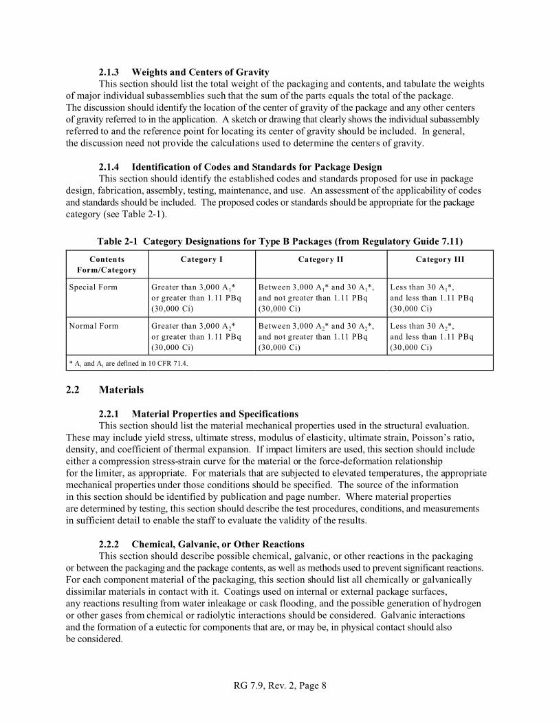
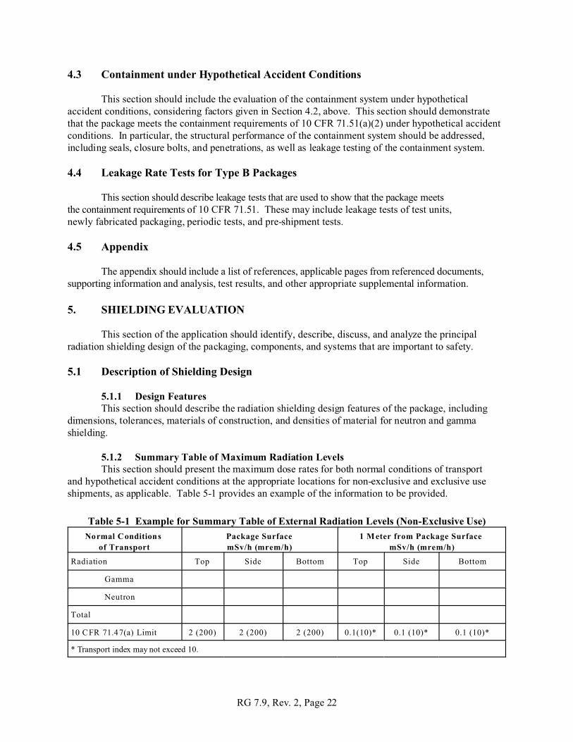
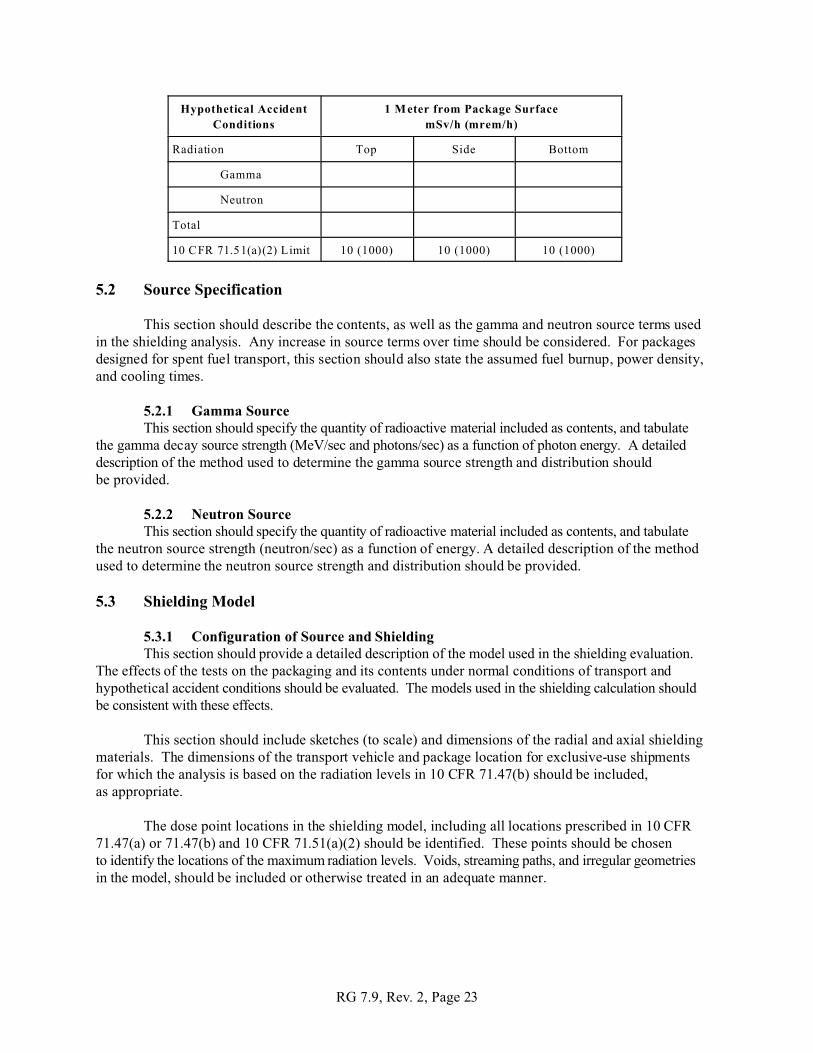