reconnaissance land resources survey · soil conservation service of new south wales ....
TRANSCRIPT

SOIL CONSERVATION SERVICE OF NEW SOUTH WALES
RECONNAISSANCE LAND RESOURCES SURVEY
TABLE TOP
Prepared for
HUME SHIRE COUNCIL
AUGUST 1985
Re port compiled by
sw Goldsmith District Soil Conservationist
PJ Barker Soil Conservationist
D Johnston Soil Conservationist
Material rray not be extraeted from this report for publieation without the permission of
the Commissioner Soil Consermtion Serviee of NeuJ South Wales
C 0 N T E N T S
INTRODUCTION 1
PHYSICAL FEATURES 3
Climate 3 Landform 3 Geology and Soils 3
RURAL CAPABILITY 10
Land Suitable for Regular Cultivation 10 Land Suitable for Grazing with or without Occasional Cultivation 13
URBAII CAPABILITY 15
Class B 15 Class C 17 Class D-fw 17
RECOMMKRDATIOBS FOR SUBDIVISION PIANRIRG AIID LAND MANAGEMENT 19
Rural Land Use 19 Rural Residential Land Use 19 Urban Land Use 20 Public Roads Drainage Facilities and Individual Allotment Construction Activities 21 Prescribed Streams 22
BIBLIOGRAPHY 23
APPERDIX I - GUIDELINES FOR SEDIMENT AND EROSION CONTROL 24
APPENDIX II - DRAINAGE MANAGEMENT 27
FIGURES
Figure 1 - Locality Diagram 2 Figure 2 - Soils Map 4 Figure 3 - Reconnaissance Rural Capability Map 11 Figure 4 - Reconnaissance Urban Capability Map 16
INTRODUCTION
This report has been compiled for the Hume Shire Council in response to the high demand for residential and rural residential development on land surrounding Table Top The survey area lies approximately 15 km north of Albury and to the west of the Hume High-way It adjoins the north western corner of the designated area of the Albury-Wodonga Development Corporation (Figure 1) This designated area has been previously describedmiddot in Junor Emery and Crouch (1977) Data from this previous study have been utilised in this report
Physical resource data have been collected in the survey area This includes data relating to climate landform geology and soils The characteristics of the soils relating to erodibility drainage stability and development limitations have been assessed The Services rural and urban capability classifications have been used to evaluate the physical 1 imitations of the Table Top area for rural residential use This capability information will help Council to reach a balance between various land uses in the area select the most suitable sites for development and minimise the erosion hazards associated with various forms of land use
This survey and accompanying maps are intended to form a basis upon Which planning considerations should be imposed to help in land use allocation in the Table Top survey area
The soils rural capability and urban capability maps of the Table Top survey area have been prepared at a scale of 110 000 The maps should not be enlarged for use at a scale larger than 1 10 000 nor should they be regarded as providing a detailed appraisal of individual development areas within the survey area
FIGURE 1 I
Locality Diagram
RECONNAISSANCE LAND RESOURCES SURVEY
TABLE TOP HUME SHIRE
I Scale
km-4 2 0 8 12 km
MN
3
PHYSICAL FEATURES
CLIMATE
The annual median rainfall at Table Top is approximately 650 mm and is winter dominant Winter rainfall is more reliable than summer rainfall Further during winter prolonged wet periods cause saturated soil conditions on poorly drained soils This necessitates the incorporation of drainage and other soil conservation ~rks
Low temperatures restrict growth during the winter months The spring and autumn months are the most favourable for plant growth due to the combination of moderate temperatures and adequate soil moisture regimes
LANDFORM
The dominant landform feature of the survey area is a granite hill Which is located on the southern boundary west of the Hume Highway Landform relief decreases to the northwest and southeast of this hill To the north landform relief decreases towards Sandy Creek which flows in a north easterly direction into Bowna Creek and then into the Hume Weir
pound Most of the survey area is comprised of footslopes whichmiddot are traversed by natural drainage areas and watercourses
GEOLOGY AND SOILS
The survey area is comprised of residual and colluvial deposits derived from underlying Silurian granite These deposits occur on the hills ridges and footslopes in association with scattered outcrops of Silurian granite The remaining low-lying areas are comprised of unconsolidated deposits of clay and silt
Six major soil map units have been identified in the survey area (Figure 2) and five of these have previously been described Junor et at 1977 One new soil map unit was identified during the survey of the Table Top survey area Soil map unit boundaries were delineated by field investigation using auger sampling to a depth of approximately 50 cm At selected sites soils were examined to a depth of 150 cm
The soils descriptions with the exception of map unit F soils are based on those soil groups in Junor et at (1977) with minor modifications Soils have been classified using the Northcote Factual Key (Northcote 1979)
4
Figure 2
SOIL CONSERVATION SERVICE OF NSW I
RECONNAISSANCE LAND RESOURCES SURVEY I
TABLE TOP I
HUME SHIRE
SOILS SCAI (
GN
NORTHCOTpound SOIL DOMINANT SOIL5 CLASSiriCATIONS
Variable Jlt lll Uc 1middot21 Dy pound1
Yclrow OvplcJC SoHbull Py lmiddotllDv 2 llPyJ lZ Mottl(d Ycllow Ooplcbull Soilamp Ov J 21 Oy ll OyJ 42
DvJ 12
411vviot Solla
MAP MAJOR LIMITATIONS UNIT
~loo~
Qock ovtcroobull ~oil CrOdtbtlliy Scotonol ltwotcrtoetng toobullbull ~oacnt hotord CL] Slope Shollow bulloil dcpth (in orco-J ltolotcd OTCOI or mop un1t t 011bull Slope
Sobulll cro~bullbihtv laolotcd orcobull of mop unfit_ Subao1l pcrrncoblrty
~it crodbullbiltiy Scobullonot bullofcr-loggtng 1o~ogrop~bullc hnbullio11on Wct 6o1l bullbullrcngH-1
nood~9
s
Map Unit A - Granite Hi 11 Soils Group - Sands and Si U()eous Sands
Q()()Urgteence
These soils occur on a small area of rounded granite hills situated on the southern boundary of the survey area
ChaIooteristws
These soils strongly reflect the grain size and mineralogishycal composition of their granitic parent material The preshydominant soils are sandy throughout A bleached soilA2 horizon overlies a White or yellow grey mottled B soil horishyzon (Uc 221) or a deep light brown sand with minimal soil profile developnent (Uc 121) These soils are slightly acidic throughout They are highly erodible and in some situations subject to failure by mass movement
Variabi U ty
These soils are usually sandy Soil profile developnent varies from uniform sands (Uc 1 21) to duplex bleached soils (Dy 341) with sandy clay B soil horizons
Identifying Features
1 Rounded hills with granite outcrops
2 Coarse sandy textured soils derived from granitic parent material
Current Land Use
Grazing recreation
Physwat Constraints to Deve opment
1 Slope gradient 2 Rock outcrop 3 Soil erodibili ty 4 Seasonal waterlogging 5 Mass movement hazard
Map Unit B - St Johns Soils Group - Massive Red Earths
0()currence
These soils dominate the crests of low hills throughout the survey area They are generally associated with small granite rock outcrops near the ridge tops and overlie yellow clays further downslope
6
Chara~teristi~s
Low ridges in an undulating landscape define this soil map unit Soils are predominantly massive red earths (Gn 212) Red duplex soils (Dr 212) also occur having A2 soil horishyzon development and greater texture contrast within the soil profile
The main soil textures are clay loam or sandy clay loam A horizons over silty clays or light clays The clay content increases with depth The C bedrock horizon consists of weathered granite near the crests Yellow medium clay B2 soil horizons occur further downslope The soil is slightly acidic (65) throughout the profile
VariabiU ty
The soil predominantly consists of massive red earths (Gn 212) These are bordered downslope by map unit C soils yellow duplex soils Small areas of map unit E soils mottled yellow duplex soils with a moderate to high shrinkshys well potential occur in depressions these areas impose additional developmental constraints
Identifying Features
1 Red clay B soil horizons 2 Minimal Az soil horizon development 3 Clay loam or sandy clay loam A1 horizons
Current Land Use
Grazing cropping in selected areas
Phys~al Constraints to Development
1 Slope gradient 2 Shallow soil depth near the ridge crests 3 Isolated areas of map unit E soils middot
Map Unit C - Thurgoona Soils Group - YeUau DupLex Sois
O~curren~e
These soils occur below map unit B soils on low ridges throughout the survey area
Chara~terist~s
Yellow duplex soils (Dy 222 with areas of Dy 212 and Dy 322) occupy midslope areas below map unit B soils The dominant soil has a clay loam to loam A horizon overlying a light clay yellow B soil horizon An A2 soil horizon may or may not be present
7
VariabiU ty
There is considerable variation within the soil profiles The development of the A2 soil horizons and the presence of mottles in the B soil horizons vary The colour of the B soil horizons is also variable and may sometimes be orange rather than yellow
Identifying Features
1 Clay loam to loam A soil horizons 2 Bright yellow B soil horizons 3 The soil horizons if present are relativelyA2
shallow - less than 20 cm
Current Land Use
Grazing cropping in selected areas
Physicat Constraints to Devetopment
1 Slope gradient
Map Unit D - Ettaniogah Soils Group- Mottted YetLau Duptex SoUs
Occurrence
These soils occur over the majority of the survey area They are found on large areas of footslopes
Characteristics
Soils are mottled yellow duplex soils (Dy 322 with areas of Dy 332 Dy 342 and Dy 312) They are located lower downshyslope than map unit B and C soils Loam A soil horizons overly yellow light to medium clay B soil horizons that
usually contain red or orange mottles Unbleached shallow A2 soil horizons are usually present
VariabiU ty
There is considerable variation in the development of the A2 horizons in these soils Towards the lower boundary of these soils and in poorly-drained areas the A2 soil horishyzons become deeper and bleached and the colour becomes duller
At the upper soil boundary mottles in the B soil horizons and Az soil horizon may be absent Small areas of map unit E soils occur in drainage depressions imposing a developshyment constraint
8
Identifying Features
1 Loam A horizons t 2 soil horizons which are usually unbleached A2 3 Red or orange mottles in the B soil horizons i
~I
Current Land Use
Grazing
Physi~al Constraints to Development
1 Soil erodibility 2 Isolated areas of map unit E soils 3 Subsoil permeability
Map Unit E - Wirlinga Soils Group - Mottled Yellav Duplex Soi Zs
O~oorren~e
These soils occur on gently sloping areas below map unit D soils They receive extensive seepage water from adjoining upslope areas
Chara~teristi~s
These soils are mottled yellow duplex soils (Dy 342) They are readily recognised by the presence of deep bleached A2 soil horizons which overlie olive brown mediun to heavy clay B soil horizons which usually exhibit grey mottles
The A2 soil horizons are always greater than 40 cm in depth strongly bleached and contain ironstone nodules
r VariabiU ty i
Although these soils are relatively consistent throughout there is variation in mottle development and the conshycentration of ironstone nodules in the A2 soil horizons
Identifying Features
1 Very deep A2 soil horizons 2 Olive brown mottled B soil horizons
Current Land Use
Grazing cropping in selected areas
Physi~al Constraints to Development
1 Soil erodibility 2 Seasonal waterlogging 3 Topographic location 4 Low wet strength of the A soil horizons
9
Map Unit F - Sandy Creek Alluvium Soils Group - A11uvial Soils
Oecurrenee
These soils occur on the floodplain of Sandy Creek
Charaeteristies
These soils are typicalmiddot layered alluvial tures ranging from sand to light sandy bedload of Sandy Creek consists mainly of c
soils with clay loam oarse sand
texshyThe
VariabiU ty
While the textures of these soils are usually sandy loam or light sandy clay loam areas of deep sands also occur
Identifying Features
1 Layered alluvium 2 Textures ranging from sand to light sandy clay loam 3 Location- the floodplain of Sandy Creek
Current Land Use
Grazing
Physwal Constraints to Deve lopment
1 Flooding
10
RURAL CAPABILITY
The rural capability classification used State-wide by the Service provides information on the optimum potential use of the land and its long term viability when used for various agri shycultural purposes (Anon 1975) It accounts for the environmenshytal factors that may limit the use of the land These factors include those of widespread influence such as climate terrain slope and soil erodibility and those of a more local influence such as soil depth water holding capacity wetness rockiness existing soil erosion salinity and pH
The survey area has been classified into a number of rural capashybility classes according to the capacity of the land to sustain permanent rural production In order to achieve this potential specific soil conservation and land management measures are required to maintain the soil resource These classes are shown on the Rural Capability Map (Figure 3)
Land which is used beyond its capability can be expected to deteriorate The consequent soil erosion can be rapid adversely affecting the immediate area and adjoining lands by the deposishytion of sediment This results in loss of production and pershymanent damage to the soil resource
I rmiddot
LAND SUITABLE FOR REGUlAR CULTIVATION
CLass II
Land in this class accounts for most of the survey area It is found on footslopes with slope gradients below 5 per cent usually with map unit D soils
Soil erosion can be controlled by simple land management practices These include contour cultivation on the steeper slope segments conservation cropping techniques (eg stubble retention and direct drilling) and adequate crop rotations which include a pasture phase
CLass III
This class is mostly comprised of sideslopes and footslopes in conjunction with map unit B and D soils Slope gradients range from 5 to 10 per cent
LFigure 3
SOIL CONSERVATION SERVICE OF NSW I
RECONNAISSANCE LAND RESOURCES I
TABLE TOP I
HUME SHIRE
RURAL CAPABILITY SCAI (
GN
11
SURVEY
NOTE See page 12 for legend
12
RURAL CAPABILITY
0 z N lt (
2 ~ ~ 5
z 0
~ u
lt 5 8
lAND CLASSIFICATION AND SOil CONSERVATION PRACTICES
c 2
middot~ u
0 ~ e 0
c 2
~ - u
0 z
11
Ill
IV
V
VI
VII
VIII
u
No JPeltMJI soil conMNation works 01 procttces
Soil consHltOtlon practices such os strip cropping conMrwotion tillage and odequoht crop rotation
Str~o~eturol soil conwrvotion ltwork I wch as graded bok wotwoyl and diveuion bonb toge~et with Jail cons-ervation proctices 1uch os conservation tillage and odequote crop rotation
Soil conHrvotion practices such os posture improvement bull 1tock control application of fertilizer and minimal cultivation for the bullstoblishment or re-establiShment of permonbullnt posture
Structural soil consetvo lion works such os absorption bonk1 divenion banks and contour ripping bull together ltwith the practices os in Class IV
Soil conwration practices including limitation of
stock btoodcosting of seed and fertilizer bull prventian
of firbull and destruction of vermin May include
some i1olated structural works
lond bett protected by green timber
Chff~ lolres Of swamp~ ond other lends unsuitable for ogrfcuhurol and postoral production
Urban orCOs
Montng and quorrytng OteO~
NOTE - ll ClASSES MAY NOT OCCUR ON THIS MP
INTERPRETATIONS AND IMIliCATIONS
Land suitable for a wide variety of uses Where oilbull ore fertile t+i6 is lond with t~ hghest potentbullol for ogncuhure and moy be cuhiyenGted fot -gW ond fruit product1on cereal and other groen crops enfigy crops foddw ond forage crops and sugar cane in f)eCtfic areas lncludsprime ogricuhurol lond
Usually gttnlly tlopbullng land s1utoble for a -idc Yoriety of ogriculturol uwa Has o high potential for production of crops on f_tile $0tiS timilor to Clan I but increasing limitottons to production due to Jite conditions Includes pri~ agricultural land-
Sloping lend suitable for cropping on o rotational basi1 Gnerally ud fot the productbullon of the ~mbull type of crop os listed for Clou 1 olt~h productivity will vary de~nding upon soil fertility Individual yieampcb may be the some as for Claues I and 11 but increo1ing rbull1trictions d11e to tt efOiion hazard will reduce the totot yield over time Soil er~ion problems ore often MYere Generally foir to good ogrtcuhural land
land not suitable for cultivation on a regular bas-is owing to limitationamp of tlope4 gradient sobulll etosion bull shollowneu or rockine~t climate or a combination of thesbull focton Compri1es the better dosses of grazing fond of the State and can be cultivated for on occasional crop porticulorly a fodder crop or for pasture wol Not luited to the range of ogrbullcultural Ulft listed for Claua I to UJ If uwrd for
middothobby forms- adequate provision s-hould be made for water supply effluent disposol and ~ection of safe building 1ites and accbullu roods
land not suitable for cultivation on a reguar basis owing to con1idetoble limitations of ~lope- gradient soil erosion shollowneu laquo rockincu climate Of o combination of these factors bull Sofl ero~ion problems ore often severe Productioo is generally Jower than for grazing 1onds in Class IV Con b cultivated for on occoslonol crop particularly o fodder crop or for pos1urc reol Not wited to the ~e of ogriculturol uses hsted for Classes I to 111 If usd for hobby fornis od~uate prowision should be mode for WOter supply effluent dispotol and selection of sofe building site$ and occess roods
Productivty 11 vary due to the- soil depth and th soil fertility Comprises the leu productive grozing lands If used forhobby forms adequate provision should be mode fO water wpply bull effluent disposal ond wlection of safe building sites ond access roods
Generally comprises areas of steep slopes shallOW soils andor rock outcrop Adequate ground protectton must be moinrained by lim1ting grazing ond min1mising damage by f~re Deslrucrion of trees is not generally recommencfcd but portlol ct-aring for groung purposes under shtct management control~ con be prachsed on Jmall oreo~ of low eroston hazard Where clbullonng of thesbull lands has O(Curred in the post unstoble sorl ond terrotn site-s s-hould b rbullturned to timber cover
land unusobl~ for agricultural or pa~toral uSfl Rlaquoommended uses ore those comporile w1th the preservohon of the natural vegctohon nomcly water supply catchm~nh wildlife refugeS not~nol and state parks and seen~ areas
ClASS SUBSCRIPTS
d
SPECIAl USES
Terrom developed for o 1pbullc1foc crop (capability clou range lv to Vlll o o reult of he combbullnahobull of portbullculor ~1
teuo domotolt and econombullc condtttonS Thbull dou tnltludbull vlth crop1 a~ grope bononos avocados and pneopple~gt
Terrom developed for onten~ivbull ogrculturol production and QS)Q(IOfed wtth flood lrttgotion The clou tncluds land developed for ltofton and t1Ce prod1ol(t10n
13
Soil erosion can be controlled by the use of structural soil conservation measures Alternately very strict land manashygement practices can be implemented to mitigate erosion In the latter case this will involve manipulating the cropping or rotation phases to avoid periods of high soil erosion hazard
LAND SUITABLE FOR GRAZING WITH OR WITHOUT OCCASIONAL CULTIVATION
Class IV
Land of this class is found on sideslopes with map unit B and D soils Small areas of footslopes with map unit E soils are also class IV land Slope gradients range between 0 and 15 per cent usually being in the range of 10 to 15 per cent on the sideslopes
Soil erosion can be controlled by certain land management practices These include the establishment of improved pastures stock control (limiting stock numbers and moveshyment) and the application of fertiliser The land is suitable for occasional cultivation it cannot produce tW) consecutive annual crops without significant soil degradashytion Where crops are grown it is necessary to establish a rotation system which will minimise soil erosion and mainshytain soil structure and fertility
Stocking rates should be at a level suitable for the mainshytenance of vegetative ground cover and mitigation of soil erosion
Class V
(i) All natural drainage areas and waterways including Sandy Creek are included in this class These areas are discussed under urban class D-fw
It is important for Council to recognise the need to apply intensive soil conservation measures on this class to miti shygate and control soil erosion Use of this class for grazing should be minimised
Sandy Creek is listed as a Prescribed Stream under Section 26D of the Water Act 1912 Section 26D of the Act provides that a person shall not except with the authority of the Catchment Areas Protection Board
(a) ringbark cut down fell poison or otherwise destroy or cause to be ringbarked cut down felled poisoned or otherwise destroyed or
j I II I
14
(b) top lop remove or injure or cause to be topped lopped removed or injured
any tree situated within or within 20 metres of the bed or bank of any river or lake or section of a river to which this Section applies
(ii) There are small areas of this class comprised of sideslopes as well as isolated crests and footslopes on map unit A B and D soils
These areas require the same type of land management practices as outlined for class IV land
15
bull
URBAN CAPABILITY
The Service uses an urban land capability classification system State-wide It is based upon an assessment of the interaction between landform soils and surface drainage characteristics and the influence of these physical features on land use for urban development An outline of the system is presented in Hannam amp Hicks (1980)
Three primary urban capability classes have been defined on the Urban Capability Map (Figure 4) The constraints to development for the various soils are outlined in the Geology and Soils Section of this report These should be carefully considered during the planning and development phases of any proposed urban development
Class B
This class occurs over most of the survey area It is found predominantly on footslopes with map unit D soils Slope gradients range up to 5 per cent This class also occurs on crests sides1opes and footslopes with map unit B C and D soils with slope gradients up to 10 per cent
The major constraints to urban development are high soil erodibility the generally poor permeability of the subsoils and isolated areas of poorly drained map unit E soils
The poor permeability of the subsoils will impose limitashytions regarding septic absorption systems Any effluent which collects in the subsoil and moves laterally through it will finally enter local drainage lines or rise to the land surface in downslope positions An appropriate effluent disposal system needs to be provided
Careful design and placement of roads across the class will assist in the control of surface water movement from road pavements and allotments
To mitigate erosion construction techniques which avoid cut and fill earthworks and minimise ground disturbance are recommended A good groundcover of vegetation should be maintained to prevent erosion of bare soil surfaces
Areas of this class with slope gradients below 5 per cent are capable of supporting both extensive building complexes and residential development Areas within this class that have slope gradients between 5 and 10 per cent are capable of supporting residential development
Adequate precautions such as those outlined in Sections 2 45 53 and 6 of Quilty Hunt and Hicks (1978) should be f allowed during development of this land
16
f
middot~middot
Figure 4
SOIL CONSERVATION SERVICE OF N SW I
RECONNAISSANCE LAND RESOURCES SURVEY I
TABLE TOP I
HUME SHIRE I
URBAN CAPABILITY SCAlE
1
DEGREE OF LIMITATION MAJOR LIMITAliO~ CAPABILITY CLASS Soil croclibilify bullololcd orbullot of uaaonbulll bullbulltrlottlnt ~ bullbullil
middot Pbullrmbulla-ihty Slope ~ ldcntial o lopmctt
rlooolng
Minor to Mod~rolc
Oroinoabull flcbullc
bull[ahneivc amputldin Comolcut
17
Class C
This class occurs mainly on sideslope areas with map unit A and B soils and slope gradients between 10 and 15 per cent There are also small areas of this class which are comprised of sideslopes on ma-p unit D soils with slope gradients betshyween 10 and 20 per cent
The principal constraint to urban development is the slope gradient of thfs class Uncontrolled development wi 11 lead to sheet and gully erosion and scouring of cut and fill batshyters Care should be taken with surface drainage and the disposal of stormwater Road batters and embankments should be formed to stable grades and adequately protected by vegeshytative and structural measures
To minimise erosion construction techniques which avoid cut and fill earthwrks and minimise ground disturbance are recommended A good groundcover of vegetation should be maintained to prevent erosion of bare soil surfaces
This class is capable of supporting residential development Sections of Quilty et at (1978) relevant to development of this class include 2 3 45 and 6
Class D-fw
Natural drainage areas and watercourses including Sandy Creek comprise this class Most slope gradients are less than 5 per cent However in the southern part of the surshyvey area slope gradients up to 15 per cent occur
This class of land is subject to periodic flooding and seasonal waterlogging Hence it should be retained as part of an open natural drainage system for the control and disposal of runoff from the survey area It may be possible to redirect water from some minor drainage areas and watershyways to form a large open drainage system However any redirection of water flows should be subject to further hydrological investigation Sandy Creek is listed as a Prescribed Stream under Section 26D of the Water Act 1912 and must be treated accordingly
Significant hydrological changes will occur in the catchment area of a watercourse When it is developed These changes involve increases in runoff volume and peak discharges eroshysion of the drainage channels and sedimentation and flooding of the lower-lying terrain The recommended approach to control these problems involves the development and manageshyment of grassed drainage reserves Urban development should not encroach onto drainage reserves or flood flows will be impeded
18
(middotmiddotshy
Flooding of the low-lying sections in tke survey area may be reduced by installing retarding basins within the drainage reserves These impound and regulate the flow of runoff waters Hence the time of concentration of runoff is increased and peak discharges are reduced
19
RECOMMENDATIONS FOR SUBDIVISION PIANNIHG AND LARD MANAGEMENT
RURAL LAND USE
Classes II and Ill can be used for regular cultivation while Classes IV and V are suitable for grazing with or without occasional cultivation
For each specific class recommended land management pracshytices as outlined in the Rural Capability section of this report should be adhered to so that soil erosion is minishymised
RURAL RESIDENTIAL LAND USE
All roads and access tracks require the application of soil erosion control techniques Apart from cultivation roads and access tracks are the greatest contributors to acceshylerated soil erosion in the rural environment They contrishybute to erosion by destroying ground cover breaking down the soil surface increasing runoff diverting and conshycentrating runoff and causing unstable sections to develop in watercourses
Structural soil conservation measures such as banks should be planned on a sub-catchment basis The placement of these structures becomes critical where closely spaced allotment boundaries occur Boundaries should be placed to ensure effective design and maintenance of structural soil consershyvation systems
Land should be sub-divided into lots that are economically viable and which suit the needs of the landholder Economic constraints in small land units can lead to neglect rejecshyt ion or long term delays in implementation of necessary erosion control measures Neglect can result where land is held primarily as an investment or for a ~ekend retreat Rejection may occur where economic necessity demands that land be used beyond its capabilities Long term delay in implementation of erosion control measures may be due to the inability of holders of small parcels of land to finance necessary conservation measures
Potential land use activities must be considered in the sUb-division design Poorly located boundaries can lead to difficulty in the design and implementation of practical systems of land use
20
f shy
Lots must be of a sufficient size to allow workable lot layout and design This is critical with small allotments and steep terrain Options for fencing access building sites earth dams effluent disposal fire management and erosion control works are limited on small allotments
Subdivision design should allow essential erosion control works to be effectively installed and maintained These works should be installed before subdivision is completed
Intensive land use activities must order to minimise soil erosion
be subject to controls in
Each allotment must have a reliable and adequate water supply Suitable sites should be available on each allotshyment to permit the construction of stable dams of adequate capacity that will not aggravate erosion hazard
Allotment boundaries are ideally located along ridges approximately on the land contour Permanent creeks can provide suitable boundaries in places but fencing mainshytenance is generally costly in such areas Boundaries along intermittent flow lines are undesirable
URBAN LAND USE
Extensive building complexes should be confined to Class B where slope gradients are less than 5 per cent
Urban residential development can be undertaken on Classes B and C provided development is consistent with the physical constraints and erosion potential of these classes An effective effluent disposal system must be provided Road and lot runoff must be adequately managed to avoid pollution of low-lying land and Sandy Creek
Construction should not be permitted on Class D-fw This land should be retained for drainage reserves and open space
Hydrological Management The existing sub-catchment layout and natural drainage netshywork should be retained in the planning and design of any d evelopnen t within the survey area This avoids downstream damage from flooding and excessive sedimentationbull
bull
21
f
middot~middot
Runoff flow velocities and peak discharges should be controlled by
carefully controlling developnent on the margins of watercourses and within the respective catchment areas and
use of retarding and sediment basins as part of the planning and development process
Sediment and erosion control techniqoutlined in Quilty et al (1978) and report should be adopted
ues App
and endix
gI
uideof
lines this
PUBLIC ROADS DRAINAGE FACILITIES AND INDIVIDUAL ALLOTMENT CONSTRUCTION ACTIVITIES
Stable all-weather roads should be provided to a point on each allotment from which stable internal access roads can be made
Roads should not be placed on unstable areas such as steep slopes or located where seasonally high water tables occur
Water should not be concentrated by roadways or other works on unstable or erodible areas
A drainage system should be designed that will assist in the maintenance of stable flow lines rather than initiate or increase erosion and sedimentation within them (See discussion under urban class D-fw and Appendix II in this report and Section 33 of Quilty et al (1978))
Sediment basins should be installed on watercourses to reduce the movement of sediment out of subdivisions during the construction phase (See Appendix II of this report and
middot Section 2 8 of Quilty et al (1978))
Batters should be properly lised by revegetation or Appendix I of this report Quilty et al (1978) )
The general principles of and revegetating disturbed Appendix I of this report (1978))
formed and subsequently stabishyby structural measures (See and Sections 21 and 632 of
saving and respreading topsoil areas should be followed (See and Section 6 of Quilty et al
22
I
middot~middot
PRESCRIBED STREAMS
Sandy Creek needs to be managed in accordance with the requireshyments outlined in Section 26D of the Water Act 1912
23 bull
BIBLIOGRAPHY
ANON (1975) Planning Land Use Soil Conservation Service Extension Handbook No 3 Soil Conservation Service of New South Wales
EMERY KA (ed) (1981) Joint Shires Study Soil Conservation Service of Nsw
HANNAM ID and HICKS RW (1980) Soil Conservation and Urban Land Use Planning J Soit Cons NSW 36 (3) pp 134-145
JUNOR RS EMERY KA CROUCH RJ (1977) Land Resources Study of the Albury-Wodonga Growth Centre in New South Wales Soil Conservation Service of New South Wales
NORTHCOTE KH (1979) A Factuat Key for the Recognition of Austratian Soits Rellim Technical Publications South Australia
QUILTY JA HUNT JS and HICKS RW (eds) (1978) Urban Erosion and Sediment Control Soil Conservation Service Technical Handbook No 2 Soil Conservation Service of New South Wales
24
APPERDIX I
GUIDKLIRKS FOR SEDIMERT AND EROSION CONTROL
Guidance in the implementation of these recommendations should be sought from the Albury office of the Soil Conservation Service as
middotplanning and construction proceed
A range of general recommendations aimed at the control of eroshys ion and sedimentation during development should be applied to the proposed rural residential development These are as follows
(a) Development should be scheduled to minimise the area disturbed at any one time and to limit the period of surface exposure
(b) Development should be designed to minimise alteration of the natural landscape Cut and fill and general grading operashytions should be limited to the minimum necessary for deveshylopment
(c) Disturbance of vegetation and topsoil should be kept to the minimum practicable This provision is critical on steep slopes
(d) Where development necessitates removal of topsoil it should be stockpiled for later respreading The stoCkpiles should not be deposited on or adjacent to watercourses If the topsoil is to be stored for lengthy periods (six months or longer) a vegetative cover should be established to protect against erosion
(e) Exposed areas such as construction sites should be protected by locating temporary banks and ditches upslope to contain and divert runoff where necessary
(f) Temporary sediment filters should be located around stormshywater inlets Runoff should be channelled through sediment basins below construction zones This will assist in the control of erosion during construction
(g) Areas that remain bare for lengthy periods during subshydivision development should be afforded temporary protecshytion Cover cropping with fast growing species (eg millet in spring and stmmer and cereal rye oats or barley in autumn and winter) or treatment with a surface mulch of straw or a chemical stabiliser would achieve this
(h) When excavations are made for conduits topsoil and subsoil should be stockpiled separately Subsoil should be replaced in the trench first and thoroughly compacted If the soil is very wet or very dry compaction may be difficult and the risk of subsequent erosion along the trench line is increased
25
f middotmiddot
Topsoil should then be replaced to a level above the adjashycent ground surface to allow for subsequent settlement
Check banks may be required along filled trench lines to prevent erosion particularly on long steep slopes
(i) Borrow areas should not be located on steep slopes or highly erodible soils Topsoi~ from borrow areas should be stockshypiled and erosion control earthworks constructed to protect them from upslope runoff where appropriate
(j) Areas of fill should be thoroughly compacted before construction
(k) Cut and fill batters should be formed to a stable slope
( 1) Where vegetative rather than structural stabilisation of batters is proposed early revegetation is essential
Batters may be protected from upslope runoff by locating catch drains immediately above them On high batters berm drains located at intervals down the batter face will prevent erosive conshycentrations of local runoff
Establishment of vegetation on batters is greatly assisted by spreading topsoil over the surface
Possible plant species for this purpose include couch ryecorn phalaris cocksfoot and rye grasses for autumn-winter establishment and couch fescue perennial rye and japanese millet for spring-sunmer establishment These should be sown at a heavy rate with a liberal dressing of fertiliser Specific advice on suitable mixtures can be obtained from the Albury office of the Soil Conservation Service
Batters may be treated with a chemical or an organic mulch following sowing This provides early stability
Hyd roseeding is an alternative batter stabilisashyt ion technique A mixture of seed fertiliser wood or paper pulp and water is sprayed onto the batter through a specially designed applicator This is a simple and effective techniquemiddot
Once vegetation is established on batters regular topdressing with fertiliser encourages the pershysistance of a vigorous groundcover of vegetation
26 bull
(m) All disturbed ground should be revegetated as soon as possible
The surface should be scarified prior to topsoil return
Topsoil structure will be damaged if it is very wet or very dry when respread
Grasses should be sown into a prepared seed bed Species suggested for batter stabilisation are also suitable for inclusion in any general revegeshytation mixture
All revegetated sites should receive an adequate dressing of fertiliser at sowing to assist vigorous establishment and growth Specific recommendations on seed and fertiliser mixtures and application rates will be provided on request to the Albury office of the Soil Conservation Service
Correct maintenance of all areas which are to remain under a permanent vegetative cover will ensure a persistent and uniform sw~rd Regular t opdressing with fertiliser is necessary in the early years of establishment Mowing will assist in weed control and promote a vigorous turf
(n) Vehicular traffic should be confined to proposed or existing road alignments where possible Temporary culverts or causeways should be provided across major drainage lines
(o) Permanent roads and parking bays should be paved as soon as possible after their formation
(p) As a large proportion of the survey area is subject to middot seepage from higher areas and presence of water tables effluent disposal options should be given due consideration
(q) Permanent drainage works should be provided as early as possible during subdivison construction
27
APPENDIX II
DRAINAGE MANAGEMENT
Existing channels should be shaped into broad trapezoidal or parabolic waterways These should have sufficient cross-section to allow passage of flows at a velocity not exceeding 2 metres per second Flows exceeding this velocity will scour vegetated channels unless a concrete lining is installed Stepped weirs or another form of suitable structure may be needed in the watershycourses of steeper catchments to prevent scouring
Trickle flows should be channelled into an underground pipe Alternatively a half-round pipe or lined invert could be located along the centre of reserves It is recommended that these have sufficient capacity to accommodate a one in one year run-off event Without this provision continuous trickle flows will erode the floor of the reserves while rushes sedges and other water loving species will proliferate along the trickle path
The channel should be stabilised with introduced grasses and legumes Best results will be achieved if couch and paspalum are SOWil in spring Turf may be laid to protect local areas where scouring occurs A heavy dressing of fertiliser should be applied at establishment and follow up applications of fertiliser may be necessary Further advice on suitable species for watershyway stabilisation in the Table Top survey area can be obtained from the Al bury office of the Soil Conservation Service
Stabilisation will be assisted if a surface binding agent such as jute mesh and bitumen straw and bitumen or another suitable chemical or organic mulch is applied at sowing This will impart temporary surface stability until vegetation is established It is a particularly desirable measure where reserves are developed after subdivision ~rks commence If possible however the drainage reserves should be formed and stabilised before any major urban development occurs
Where roadways cross drainage reserves floodways and culverts should be stabilised to withstand damage from high flows Rock grouting hay and wire netting jute mesh and bitumen or structural energy dissipators should be used below culvert outlets to alleviate potential erosion problems
Road layout should be designed to be consistent with natural conshytours of the land Table drains can then be used effectively as part of the disposal system for local surface water Both road and lot runoff should be conveyed via these waterways to the major watercourses
28
Installation of Retarding Basins and Sediment Basins
(a) Retarding Basins
Retarding basins are large storages designed to impound runoff and regulate its flow through a pipe outlet The result is to reduce peak discharges by increasing the time of concentration of runoff Provision should be made for flows greater than the flood storage capacity of the basin This could be achieved by installing an emergency spillway
Retarding basins could provide the solution to some channel erosion problems in the survey area Some pennanent water storage within them might also serve as a recreational ameshynity A full discussion of these aspects is provided in Section 32 of Quilty et at (1978)
(b) Sediment Basins
Sediment basins are temporary storages located on flow lines They can be a barrier or dam constructed across a waterway an excavated basin or both Design of sediment basins is discussed more fully in Section 28 of Quilty et at (1978) The size of the structure will be determined by the location of the drainage area soil characteristics and the rainfall pattern of the Table Top survey area
The primary function of sediment basins is to impound runoff temporarily and trap sediment A potential secondary funcshytion is to provide mitigate flooding They are designed to drain completely through a perforated drop inlet attached to a discharge pipe Sediment should be regularly removed from the basins to maintain their effective operation Therefore good access is required to facilitate sediment removal from the basin floor Basins should be as close as practical to the major source of sediment
The whole structure may be removed after the developnent a rea is stabilised or sediment can be removed and the structure can be retained as a retarding basin
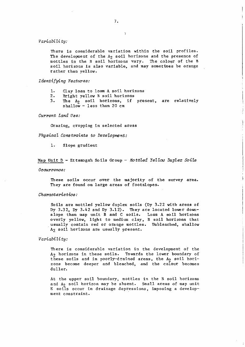
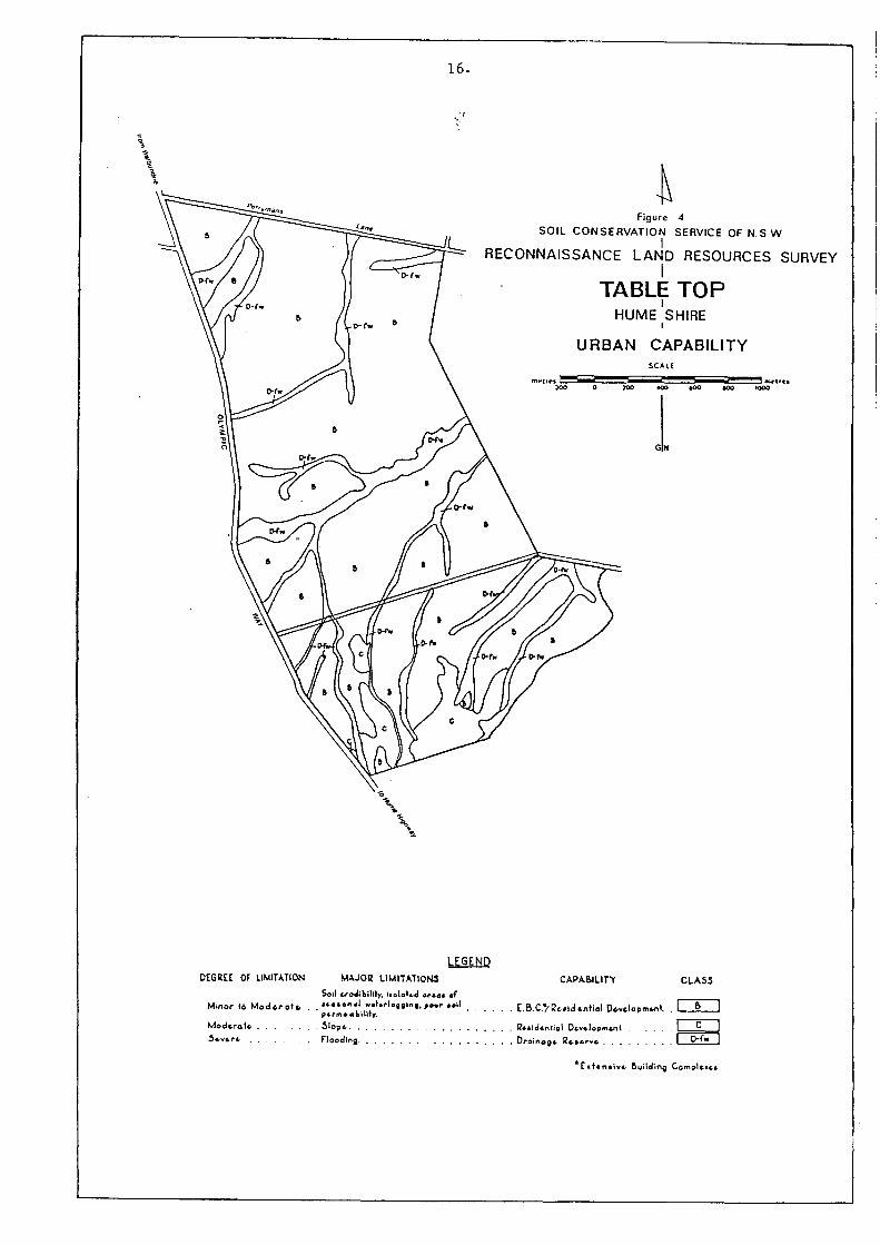