proceedings of the 10 of energy zadar, croatia, 5 -8 june
TRANSCRIPT
50
Journal of Energy
journal homepage: http://journalofenergy.com/
VOLUME 65 - 1 | 2016
Proceedings of the 10th International Conference of the Croatian Nuclear Society Zadar, Croatia, 5-8 June 2016 Paper No. 45
45-1
Cable Aging Management Program Implementation in Krško NPP-NEK
Marko Pirc NEK d.o.o.
Vrbina 12, 8270 Krško, Slovenia [email protected]
ABSTRACT
As a requirement for plant life extension for more than 40 years some additional Aging Management Programs (AMP) for passive equipment have to be implemented. The article presents overview of Cable Aging Management Program (CAMP) implementation. Program defines basic rules and initial activities for identification of adverse operation environment parameters that could lead to accelerated aging of specific materials. Samples of cables are selected based on nuclear safety and electrical equipment criticality for inspection and testing, to check functionality and prevent unexpected failure during normal operation. Acceptance criteria for environment parameters and diagnostic testing have been set. Initial visual inspection of cables condition in adverse environment and testing of sampled cables and environment are giving results for in time preventive measures. First cable aging management program is implemented since 2010 and its experience could be accommodated to other companies with cables recognized as key components.
1 INTRODUCTION
The purpose of Cable Ageing Management Program (CAMP) [1] is to provide reasonable assurance of functionality of the electrical cables with connections exposed to localized adverse environments. Identification of potential adverse localized environments or adverse service conditions and management of cable insulation and connections are its main concern. Main goal is to confirm functionality of cables for planed extended life operation more than 40 years.
CAMP defines activities on low voltage power, control, instrument and medium voltage cables with associate connections to safety related equipment (1E), critical equipment and cables identified in operating experience of plant as exposed to adverse localized environment.
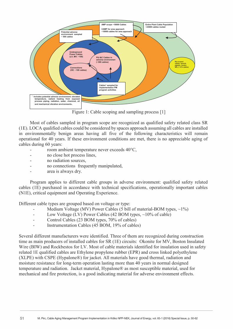
Aging Management Program for cables uses two approaches. First is visual inspection of cable areas to search for potential local adverse environment so called harsh environment or “hot spot” such as high temperature, humidity or submergence, chemical or mechanical wear. Second approach is to do additional diagnostic testing of selected cables in specific local adverse environment. In NPP Krško (NEK) there are more than 1000 km installed cables in more than 21000 circuits of different type, material and manufacturer. It is obvious, all cables could not be inspected nether tested, though scoping of most critical cables are sampled in adverse environment. Sampling approach is shown on Figure 1. CAMP is continuing process with conclusion made, if all inspected and tested cables in harsh environment are meeting acceptance criteria, whole population of cables is functional for at least next period of inspection.
M. Pirc, Cable Aging Management Program Implementation in Krško NPP-NEK, Journal of Energy, vol. 65-1 (2016) Special Issue, p. 50-62
51
45-2
Figure 1: Cable scoping and sampling process [1]
Most of cables sampled in program scope are recognized as qualified safety related class SR
(1E). LOCA qualified cables could be considered by spaces approach assuming all cables are installed in environmentally benign areas having all five of the following characteristics will remain operational for 40 years. If these environment conditions are met, there is no appreciable aging of cables during 60 years:
- room ambient temperature never exceeds 40°C, - no close hot process lines, - no radiation sources, - no connections frequently manipulated, - area is always dry.
Program applies to different cable groups in adverse environment: qualified safety related
cables (1E) purchased in accordance with technical specifications, operationally important cables (N1E), critical equipment and Operating Experience. Different cable types are grouped based on voltage or type:
- Medium Voltage (MV) Power Cables (5 bill of material-BOM types, ~1%) - Low Voltage (LV) Power Cables (42 BOM types, ~10% of cable) - Control Cables (23 BOM types, 70% of cables) - Instrumentation Cables (45 BOM, 19% of cables)
Several different manufacturers were identified. Three of them are recognized during construction time as main producers of installed cables for SR (1E) circuits: Okonite for MV, Boston Insulated Wire (BIW) and Rockbestos for LV. Most of cable materials identified for insulation used in safety related 1E qualified cables are Ethylene propylene rubber (EPR) and cross linked polyethylene (XLPE) with CSPE (Hypalone®) for jacket. All materials have good thermal, radiation and moisture resistance for long-term operation lasting more than 40 years in normal designed temperature and radiation. Jacket material, Hypalone® as most susceptible material, used for mechanical and fire protection, is a good indicating material for adverse environment effects.
Entire Plant Cable Population ~23000 cables routed
Potential adverse environment sampled ~ 500 cables
Underground Power Cables (LV, MV: ~100) P& I&C Cables in
adverse environment (~300 cables)
1 Includes potential adverse environment: elevated temperature, radiant heating from exposed process piping, radiation, water, chemical, oil and mechanical vibration environments.
Connections (OE: ~100 cables)
Cables1 sampled for implementation PM program activities
Not scoped cables: special, pigtails, vendor, WS, (~14% cables)
AMP scope ~18000 Cables CAMP for area approach ~10000 cables for area approach
M. Pirc, Cable Aging Management Program Implementation in Krško NPP-NEK, Journal of Energy, vol. 65-1 (2016) Special Issue, p. 50-62
52
45-3
2 LICENSING REQUIREMENTS AND PROGRAM OVERVIEW
NUREG-1801 Generic Aging Lessons Learned (GALL) [1] requires aging management program to detect possible aging effects on electrical cables with appropriate consideration for low voltage power, control, instrument and medium voltage cables with connections in period of plant life time. Other licensing sources were considered: Maintenance Rule (10 CFR 50.65), License Renewal Rule (10 CFR 54) and Critical Components-reliability (INPO AP-913). Their additional requirements to be in scope are cables used to mitigate accidents or transients or support emergency operating procedures, cables whose failure could cause a reactor scram or actuation of a safety-related system, Station Blackout, Fire Protection, and reliability - cables supporting the function of critical components. The CAMP is conservative and specific in activities to identify adverse environment and do the assessment on exposed and sampled cables by:
- Identification of locations and parameters where environments are more severe than the plant design environment for those areas and could cause premature aging effects.
- Visual inspection of sampled accessible cables on located adverse environment. - Evaluation of calibration and surveillance testing results to identify deviations leading to
direct testing of the circuits with involved cables and connections - Inspection for water collection in power cable manholes and draining water. - Electrical test samples of inaccessible cables in identified adverse environment. - Testing samples of power cable connections (i.e. IR camera, resistance testing, or other). - If an unacceptable condition is identified at inspection or testing, a determination is made as
to whether the same condition or situation is applicable to other (in) accessible cables. - Estimating life prediction for exposed cables with site testing, theoretical calculations or
laboratory testing to predict residual life of cable insulation. - Corrective actions with repair and replace cables are planned to eliminate and prevent aging
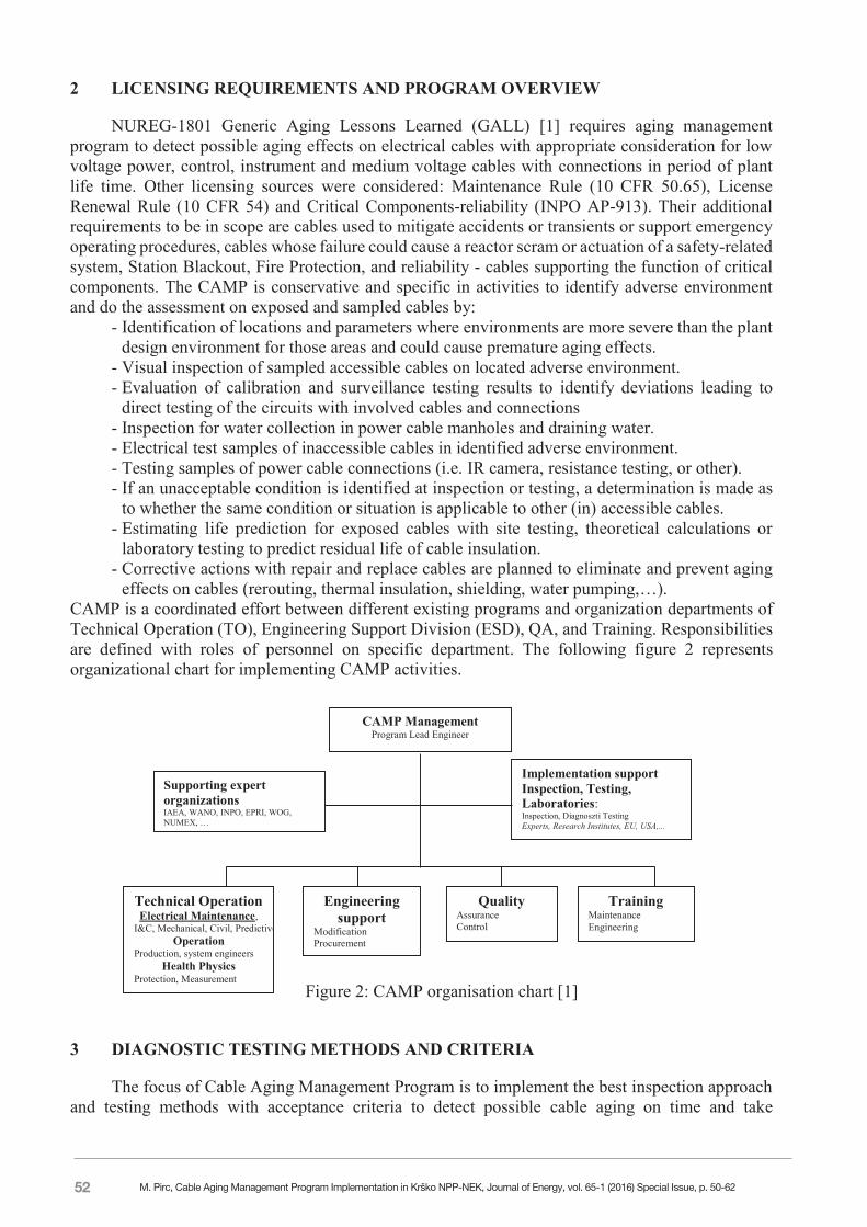
effects on cables (rerouting, thermal insulation, shielding, water pumping,…). CAMP is a coordinated effort between different existing programs and organization departments of Technical Operation (TO), Engineering Support Division (ESD), QA, and Training. Responsibilities are defined with roles of personnel on specific department. The following figure 2 represents organizational chart for implementing CAMP activities.
Figure 2: CAMP organisation chart [1]
3 DIAGNOSTIC TESTING METHODS AND CRITERIA
The focus of Cable Aging Management Program is to implement the best inspection approach and testing methods with acceptance criteria to detect possible cable aging on time and take
Technical Operation Electrical Maintenance,
I&C, Mechanical, Civil, Predictive Operation
Production, system engineers Health Physics
Protection, Measurement
Engineering support
Modification Procurement
Quality Assurance Control
Training Maintenance Engineering
Supporting expert organizations IAEA, WANO, INPO, EPRI, WOG, NUMEX, …
Implementation support Inspection, Testing, Laboratories: Inspection, Diagnoszti Testing Experts, Research Institutes, EU, USA,...
CAMP Management Program Lead Engineer
M. Pirc, Cable Aging Management Program Implementation in Krško NPP-NEK, Journal of Energy, vol. 65-1 (2016) Special Issue, p. 50-62
53
45-4
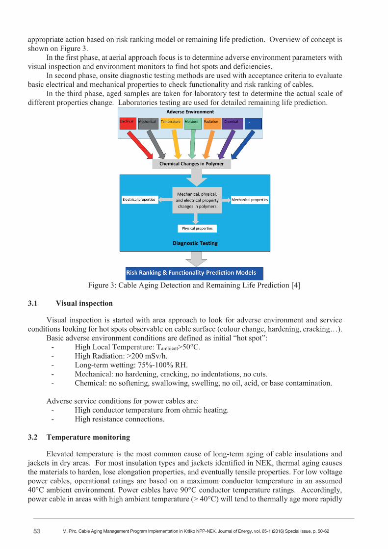
appropriate action based on risk ranking model or remaining life prediction. Overview of concept is shown on Figure 3.
In the first phase, at aerial approach focus is to determine adverse environment parameters with visual inspection and environment monitors to find hot spots and deficiencies.
In second phase, onsite diagnostic testing methods are used with acceptance criteria to evaluate basic electrical and mechanical properties to check functionality and risk ranking of cables.
In the third phase, aged samples are taken for laboratory test to determine the actual scale of different properties change. Laboratories testing are used for detailed remaining life prediction.
Figure 3: Cable Aging Detection and Remaining Life Prediction [4]
3.1 Visual inspection
Visual inspection is started with area approach to look for adverse environment and service conditions looking for hot spots observable on cable surface (colour change, hardening, cracking…).
Basic adverse environment conditions are defined as initial “hot spot”: - High Local Temperature: Tambient>50°C. - High Radiation: >200 mSv/h. - Long-term wetting: 75%-100% RH. - Mechanical: no hardening, cracking, no indentations, no cuts. - Chemical: no softening, swallowing, swelling, no oil, acid, or base contamination.
Adverse service conditions for power cables are:
- High conductor temperature from ohmic heating. - High resistance connections.
3.2 Temperature monitoring
Elevated temperature is the most common cause of long-term aging of cable insulations and jackets in dry areas. For most insulation types and jackets identified in NEK, thermal aging causes the materials to harden, lose elongation properties, and eventually tensile properties. For low voltage power cables, operational ratings are based on a maximum conductor temperature in an assumed 40°C ambient environment. Power cables have 90°C conductor temperature ratings. Accordingly, power cable in areas with high ambient temperature (> 40°C) will tend to thermally age more rapidly
M. Pirc, Cable Aging Management Program Implementation in Krško NPP-NEK, Journal of Energy, vol. 65-1 (2016) Special Issue, p. 50-62
54
45-5
if operated close to ampacity if the elevated ambient temperature was not considered in the derating process. As ambient temperature increases above 50°C, the jacket materials of some power cables will begin to thermally age. Finding a hardened cable jacket would indicate that assessment of the aging of the cable is desirable to determine if the insulation has hardened and may be susceptible to cracking and failure. Table 1 provides approximate time to the point, where jacket aging would be detectable via tactile assessment for various ambient temperatures. The values are given to show that elevated temperatures greatly reduce life. The table gives a rough indication of temperature sensitivity for identifying areas where cable condition should be assessed.
Table 1: Approximate Time When Jacket Aging Would Be Detectable (hardened) [1] Jacket Material 1 \ Temperature 50°C 60°C 70°C Neoprene 16 – 20 years 2 – 3 years Very short CSPE (Hypalon) Very long life 25 – 30 years 9 – 11 years PVC 14 – 22 years 5 – 8 years 2 – 3 years
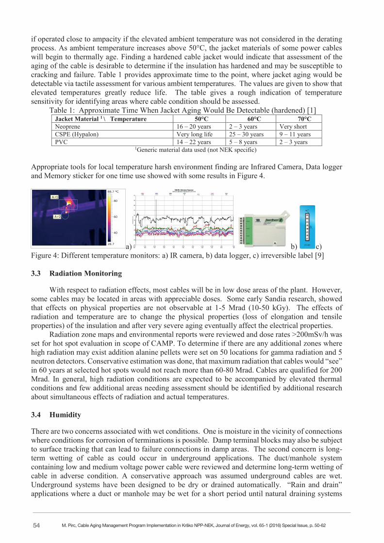
1Generic material data used (not NEK specific) Appropriate tools for local temperature harsh environment finding are Infrared Camera, Data logger and Memory sticker for one time use showed with some results in Figure 4.
A r1
A r2
28.7
88.7 °C
40
60
80
a) b) c) Figure 4: Different temperature monitors: a) IR camera, b) data logger, c) irreversible label [9]
3.3 Radiation Monitoring
With respect to radiation effects, most cables will be in low dose areas of the plant. However, some cables may be located in areas with appreciable doses. Some early Sandia research, showed that effects on physical properties are not observable at 1-5 Mrad (10-50 kGy). The effects of radiation and temperature are to change the physical properties (loss of elongation and tensile properties) of the insulation and after very severe aging eventually affect the electrical properties.
Radiation zone maps and environmental reports were reviewed and dose rates >200mSv/h was set for hot spot evaluation in scope of CAMP. To determine if there are any additional zones where high radiation may exist addition alanine pellets were set on 50 locations for gamma radiation and 5 neutron detectors. Conservative estimation was done, that maximum radiation that cables would “see” in 60 years at selected hot spots would not reach more than 60-80 Mrad. Cables are qualified for 200 Mrad. In general, high radiation conditions are expected to be accompanied by elevated thermal conditions and few additional areas needing assessment should be identified by additional research about simultaneous effects of radiation and actual temperatures.
3.4 Humidity
There are two concerns associated with wet conditions. One is moisture in the vicinity of connections where conditions for corrosion of terminations is possible. Damp terminal blocks may also be subject to surface tracking that can lead to failure connections in damp areas. The second concern is long-term wetting of cable as could occur in underground applications. The duct/manhole system containing low and medium voltage power cable were reviewed and determine long-term wetting of cable in adverse condition. A conservative approach was assumed underground cables are wet. Underground systems have been designed to be dry or drained automatically. “Rain and drain” applications where a duct or manhole may be wet for a short period until natural draining systems
M. Pirc, Cable Aging Management Program Implementation in Krško NPP-NEK, Journal of Energy, vol. 65-1 (2016) Special Issue, p. 50-62
55
45-6
where ducts slope towards manholes or other structures that are drained such that cables neither sit in nor are submerged in water for any significant period may be treated as dry with respect to cable longevity. Cables mounted on the walls of trenches and not subject to wetting along their length are considered dry. Main holes are checked monthly and water is pumped as needed to prevent wetting of cables. Periodic exposures to moisture lasting less than a few days (i.e., normal rain and drain) are not significant. Significant voltage exposure is defined as being subjected to system voltage for more than twenty-five percent of the time. Potentially wet cables not energized more than 25% of the time have a low likelihood of sustaining water related degradation. As long as the continuously energized cables remain healthy, there is little concern that the normally de-energized cables have degraded. The second half of the quote refers to impervious cable that has a metallic barrier that precludes ingress of water and 75%-100% relative humidity is considered as too high and calculated in risk ranking contribution.
3.5 Chemical
Most cables are not subject to contamination with oil or chemicals. Areas containing borates or other chemicals should be identified and evaluated for having cables. With respect to borates, deterioration of exposed terminations is more of a concern than jacket/insulation deterioration. In general, contamination with oil is more related to a spill. Cables subjected to oil contamination should be cleaned and evaluated for any effects on longevity around turbine and large oiled pumps. Some traces of mineral oils were found in special sealants on tray to conduit that might effect Hypalone jacket with softening and swallowing effect. Tests were conducted at different laboratories with no evidence on primary insulation confirmed. Visual inspection is planned on specific location with repair and replace as needed. 3.6 Ohmic heating
Current in the conductor of power cable causes temperature rise due to ohmic heating in cables, mainly at connections. The review of the power circuits load currents with respect to the ampacities of the cables. If the normal conservatisms were applied during design, cables were applied with no more than 80 percent of ampacity. Given temperature rise is proportional to the square of the current, 80 percent of ampacity should result in 64% of the allowed temperature rise. In the case of a 90°C cable in a 40°C environment, the rise at 80% ampacity should be approximately 32°C such that the conductor temperature would be 72°C. Ohmic heating should be considered in conjunction with identified adverse thermal conditions in rooms especially if ambient temperature coupled with the conductor rise result in temperatures approaching the rated temperature of the cable. There are more approaches to evaluate ohmic heating induced aging of polymers or connections:
- Tests were conducted for different materials and resulting in realistic calculated addition 14°C to 17°C temperature rise due to ohmic heating depending of material type [9].
- MV cables high electrical fields could impact impurities and voids in insulation resulting in partial discharge as microscopic arcs leading to electrical trees resulting in dielectric failure or insulation break down. We start to use partial discharge testing.
- Infrared camera - Any temperature difference above reference (dT) is a concern. Table 2 provides suggested severity ranges for evaluating electrical power connections.
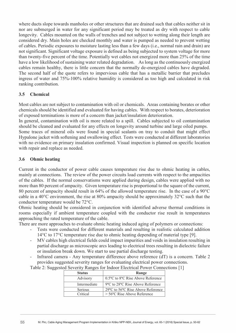
Table 2: Suggested Severity Ranges for Indoor Electrical Power Connections [1] Status Range Advisory 0.5ºC to 8ºC Rise Above Reference Intermediate 9ºC to 28ºC Rise Above Reference Serious 29ºC to 56ºC Rise Above Reference Critical > 56ºC Rise Above Reference
M. Pirc, Cable Aging Management Program Implementation in Krško NPP-NEK, Journal of Energy, vol. 65-1 (2016) Special Issue, p. 50-62
56
45-7
3.7 On site mechanical test of tensile strength - Indenter Modulus
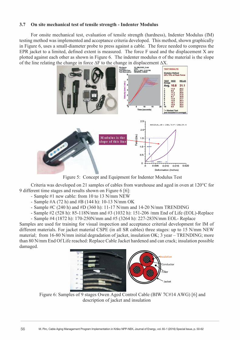
For onsite mechanical test, evaluation of tensile strength (hardness), Indenter Modulus (IM) testing method was implemented and acceptance criteria developed. This method, shown graphically in Figure 6, uses a small-diameter probe to press against a cable. The force needed to compress the EPR jacket to a limited, defined extent is measured. The force F used and the displacement X are plotted against each other as shown in Figure 6. The indenter modulus σ of the material is the slope of the line relating the change in force ∆F to the change in displacement ∆X.
Figure 5: Concept and Equipment for Indenter Modulus Test
Criteria was developed on 21 samples of cables from warehouse and aged in oven at 120°C for 9 different time stages and results shown on Figure 6 [6]:
- Sample #1 new cable: from 10 to 13 N/mm NEW - Sample #A (72 h) and #B (144 h): 10-13 N/mm OK - Sample #C (240 h) and #D (360 h): 11-17 N/mm and 14-20 N/mm TRENDING - Sample #2 (528 h): 85-118N/mm and #3 (1032 h): 151-206 /mm End of Life (EOL)-Replace - Sample #4 (1872 h): 170-250N/mm and #5 (3264 h): 227-283N/mm EOL- Replace
Samples are used for training for visual inspection and acceptance criterial development for IM of different materials. For jacket material CSPE (in all SR cables) three stages: up to 15 N/mm NEW material; from 16-80 N/mm initial degradation of jacket, insulation OK; 3 year – TRENDING; more than 80 N/mm End Of Life reached: Replace Cable Jacket hardened and can crack; insulation possible damaged.
Figure 6: Samples of 9 stages Owen Aged Control Cable (BIW 7C#14 AWG) [6] and
description of jacket and insulation
M. Pirc, Cable Aging Management Program Implementation in Krško NPP-NEK, Journal of Energy, vol. 65-1 (2016) Special Issue, p. 50-62
57
45-8
3.8 On site electrical tests
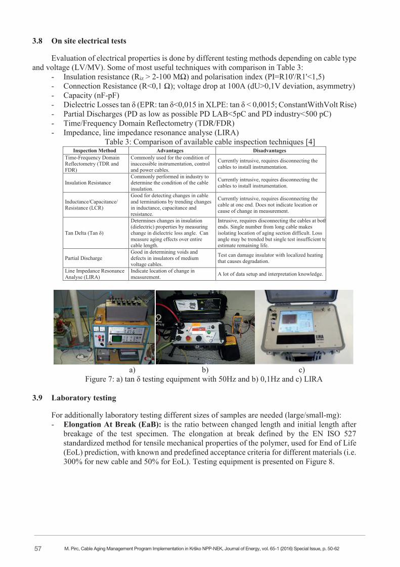
Evaluation of electrical properties is done by different testing methods depending on cable type and voltage (LV/MV). Some of most useful techniques with comparison in Table 3:
- Insulation resistance (Riz > 2-100 MΩ) and polarisation index (PI=R10'/R1'<1,5) - Connection Resistance (R<0,1 Ω); voltage drop at 100A (dU>0,1V deviation, asymmetry) - Capacity (nF-pF) - Dielectric Losses tan δ (EPR: tan δ<0,015 in XLPE: tan δ < 0,0015; ConstantWithVolt Rise) - Partial Discharges (PD as low as possible PD LAB<5pC and PD industry<500 pC) - Time/Frequency Domain Reflectometry (TDR/FDR) - Impedance, line impedance resonance analyse (LIRA)
Table 3: Comparison of available cable inspection techniques [4] Inspection Method Advantages Disadvantages Time-Frequency Domain Reflectometry (TDR and FDR)
Commonly used for the condition of inaccessible instrumentation, control and power cables.
Currently intrusive, requires disconnecting the cables to install instrumentation.
Insulation Resistance Commonly performed in industry to determine the condition of the cable insulation.
Currently intrusive, requires disconnecting the cables to install instrumentation.
Inductance/Capacitance/ Resistance (LCR)
Good for detecting changes in cable and terminations by trending changes in inductance, capacitance and resistance.
Currently intrusive, requires disconnecting the cable at one end. Does not indicate location or cause of change in measurement.
Tan Delta (Tan δ)
Determines changes in insulation (dielectric) properties by measuring change in dielectric loss angle. Can measure aging effects over entire cable length.
Intrusive, requires disconnecting the cables at both ends. Single number from long cable makes isolating location of aging section difficult. Loss angle may be trended but single test insufficient to estimate remaining life.
Partial Discharge Good in determining voids and defects in insulators of medium voltage cables.
Test can damage insulator with localized heating that causes degradation.
Line Impedance Resonance Analyse (LIRA)
Indicate location of change in measurement. A lot of data setup and interpretation knowledge.
a) b) c)
Figure 7: a) tan δ testing equipment with 50Hz and b) 0,1Hz and c) LIRA
3.9 Laboratory testing
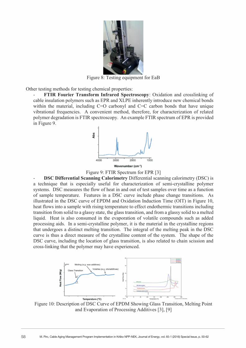
For additionally laboratory testing different sizes of samples are needed (large/small-mg): - Elongation At Break (EaB): is the ratio between changed length and initial length after
breakage of the test specimen. The elongation at break defined by the EN ISO 527 standardized method for tensile mechanical properties of the polymer, used for End of Life (EoL) prediction, with known and predefined acceptance criteria for different materials (i.e. 300% for new cable and 50% for EoL). Testing equipment is presented on Figure 8.
M. Pirc, Cable Aging Management Program Implementation in Krško NPP-NEK, Journal of Energy, vol. 65-1 (2016) Special Issue, p. 50-62
58
45-9
Figure 8: Testing equipment for EaB
Other testing methods for testing chemical properties:
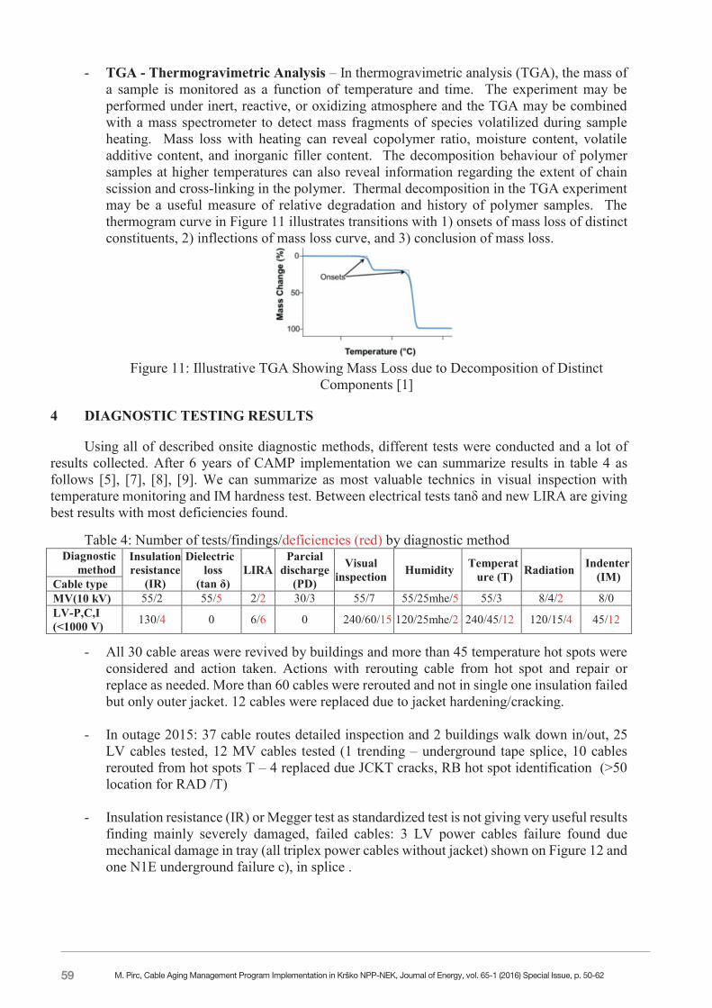
- FTIR Fourier Transform Infrared Spectroscopy: Oxidation and crosslinking of cable insulation polymers such as EPR and XLPE inherently introduce new chemical bonds within the material, including C=O carbonyl and C=C carbon bonds that have unique vibrational frequencies. A convenient method, therefore, for characterization of related polymer degradation is FTIR spectroscopy. An example FTIR spectrum of EPR is provided in Figure 9.
Figure 9: FTIR Spectrum for EPR [3]
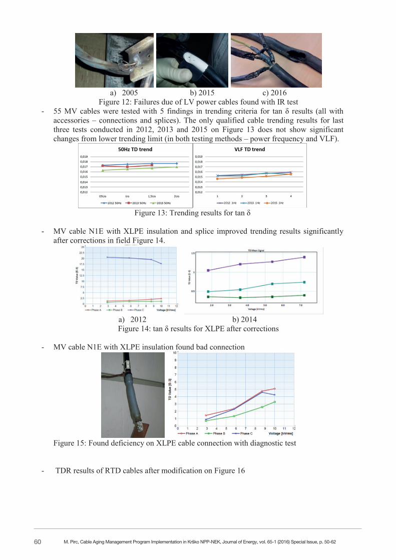
- DSC Differential Scanning Calorimetry Differential scanning calorimetry (DSC) is a technique that is especially useful for characterization of semi-crystalline polymer systems. DSC measures the flow of heat in and out of test samples over time as a function of sample temperature. Features in a DSC curve include phase change transitions. As illustrated in the DSC curve of EPDM and Oxidation Induction Time (OIT) in Figure 10, heat flows into a sample with rising temperature to effect endothermic transitions including transition from solid to a glassy state, the glass transition, and from a glassy solid to a melted liquid. Heat is also consumed in the evaporation of volatile compounds such as added processing aids. In a semi-crystalline polymer, it is the material in the crystalline regions that undergoes a distinct melting transition. The integral of the melting peak in the DSC curve is thus a direct measure of the crystalline content of the system. The shape of the DSC curve, including the location of glass transition, is also related to chain scission and cross-linking that the polymer may have experienced.
Figure 10: Description of DSC Curve of EPDM Showing Glass Transition, Melting Point
and Evaporation of Processing Additives [3], [9]
M. Pirc, Cable Aging Management Program Implementation in Krško NPP-NEK, Journal of Energy, vol. 65-1 (2016) Special Issue, p. 50-62
59
45-10
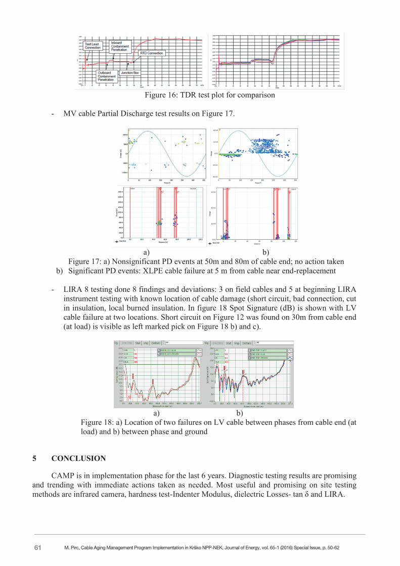
- TGA - Thermogravimetric Analysis – In thermogravimetric analysis (TGA), the mass of a sample is monitored as a function of temperature and time. The experiment may be performed under inert, reactive, or oxidizing atmosphere and the TGA may be combined with a mass spectrometer to detect mass fragments of species volatilized during sample heating. Mass loss with heating can reveal copolymer ratio, moisture content, volatile additive content, and inorganic filler content. The decomposition behaviour of polymer samples at higher temperatures can also reveal information regarding the extent of chain scission and cross-linking in the polymer. Thermal decomposition in the TGA experiment may be a useful measure of relative degradation and history of polymer samples. The thermogram curve in Figure 11 illustrates transitions with 1) onsets of mass loss of distinct constituents, 2) inflections of mass loss curve, and 3) conclusion of mass loss.
Figure 11: Illustrative TGA Showing Mass Loss due to Decomposition of Distinct
Components [1]
4 DIAGNOSTIC TESTING RESULTS
Using all of described onsite diagnostic methods, different tests were conducted and a lot of results collected. After 6 years of CAMP implementation we can summarize results in table 4 as follows [5], [7], [8], [9]. We can summarize as most valuable technics in visual inspection with temperature monitoring and IM hardness test. Between electrical tests tanδ and new LIRA are giving best results with most deficiencies found.
Table 4: Number of tests/findings/deficiencies (red) by diagnostic method
Diagnostic method
Insulation resistance
(IR)
Dielectric loss
(tan δ) LIRA
Parcial discharge
(PD)
Visual inspection Humidity Temperat
ure (T) Radiation Indenter (IM) Cable type
MV(10 kV) 55/2 55/5 2/2 30/3 55/7 55/25mhe/5 55/3 8/4/2 8/0 LV-P,C,I (<1000 V) 130/4 0 6/6 0 240/60/15 120/25mhe/2 240/45/12 120/15/4 45/12
- All 30 cable areas were revived by buildings and more than 45 temperature hot spots were considered and action taken. Actions with rerouting cable from hot spot and repair or replace as needed. More than 60 cables were rerouted and not in single one insulation failed but only outer jacket. 12 cables were replaced due to jacket hardening/cracking.
- In outage 2015: 37 cable routes detailed inspection and 2 buildings walk down in/out, 25 LV cables tested, 12 MV cables tested (1 trending – underground tape splice, 10 cables rerouted from hot spots T – 4 replaced due JCKT cracks, RB hot spot identification (>50 location for RAD /T)
- Insulation resistance (IR) or Megger test as standardized test is not giving very useful results finding mainly severely damaged, failed cables: 3 LV power cables failure found due mechanical damage in tray (all triplex power cables without jacket) shown on Figure 12 and one N1E underground failure c), in splice .
M. Pirc, Cable Aging Management Program Implementation in Krško NPP-NEK, Journal of Energy, vol. 65-1 (2016) Special Issue, p. 50-62
60
45-11
a) 2005 b) 2015 c) 2016
Figure 12: Failures due of LV power cables found with IR test - 55 MV cables were tested with 5 findings in trending criteria for tan δ results (all with
accessories – connections and splices). The only qualified cable trending results for last three tests conducted in 2012, 2013 and 2015 on Figure 13 does not show significant changes from lower trending limit (in both testing methods – power frequency and VLF).
Figure 13: Trending results for tan δ
- MV cable N1E with XLPE insulation and splice improved trending results significantly
after corrections in field Figure 14.
a) 2012 b) 2014 Figure 14: tan δ results for XLPE after corrections
- MV cable N1E with XLPE insulation found bad connection
Figure 15: Found deficiency on XLPE cable connection with diagnostic test
- TDR results of RTD cables after modification on Figure 16
M. Pirc, Cable Aging Management Program Implementation in Krško NPP-NEK, Journal of Energy, vol. 65-1 (2016) Special Issue, p. 50-62
61
45-12
Figure 16: TDR test plot for comparison
- MV cable Partial Discharge test results on Figure 17.
a) b)
Figure 17: a) Nonsignificant PD events at 50m and 80m of cable end; no action taken b) Significant PD events: XLPE cable failure at 5 m from cable near end-replacement
- LIRA 8 testing done 8 findings and deviations: 3 on field cables and 5 at beginning LIRA
instrument testing with known location of cable damage (short circuit, bad connection, cut in insulation, local burned insulation. In figure 18 Spot Signature (dB) is shown with LV cable failure at two locations. Short circuit on Figure 12 was found on 30m from cable end (at load) is visible as left marked pick on Figure 18 b) and c).
a) b)
Figure 18: a) Location of two failures on LV cable between phases from cable end (at load) and b) between phase and ground
5 CONCLUSION
CAMP is in implementation phase for the last 6 years. Diagnostic testing results are promising and trending with immediate actions taken as needed. Most useful and promising on site testing methods are infrared camera, hardness test-Indenter Modulus, dielectric Losses- tan δ and LIRA.
M. Pirc, Cable Aging Management Program Implementation in Krško NPP-NEK, Journal of Energy, vol. 65-1 (2016) Special Issue, p. 50-62
62
45-13
Laboratory test has not been required nether implemented in larger scale. It will be used only in some special examples for additional evaluation of specific effects that might be found in future.
Additional diagnostic on site and laboratory tests will help for residual life time prediction and risk ranking according to deviations between qualification test methods and real environmental conditions including simultaneous aging effects of radiation, temperature, humidity, chemicals environment and mechanical load, vibrations,... Addition testing would also help to control functionality and possible new failure mechanisms such as LOCA testing condition with lo oxygen atmosphere or inverse temperature effect including Arrhenius calculation for temperature calculation with activation energy (Ea) as temperature dependant, where small difference in material constant is giving big result change (±10 % Ea resulting double/half residual life time) [3].
Program health report and risk ranking tool are in development phase and are planned to be implemented after testing period in 2016.
REFERENCES
[1] M. Pirc, Cable Aging Management Program, TD-2D, rev.1 Nuklearna elektrarna Krško, 2011
[2] Generic Aging Lessons Learned (GALL), NUREG-1801 rev.2
[3] International Atomic Energy Agency, “Assessing and Managing Cable Ageing in Nuclear Power Plants”, IAEA-Nuclear Energy Series NP-T-3.6, 2012
[4] K.L. Simmons, , Determining Remaining Useful Life of Aging Cables in Nuclear Power Plants – Interim Study FY13, PNNL for US DOE, September 2013
[5] M.Pirc, Vzpostavljanje programa nadzora staranja električnih kablov v NEK, CIGRE Ljubljana, 2011
[6] M. Pirc, HS-2011-02-T-IM: Development of acceptance criteria for Indenter Modulus, NEK, 2011
[7] M.Pirc, Diagnostična testiranja električnih kablov v Nuklearni elektrarni krško, CIGRE Laško, 2013
[8] M.Pirc, Rezultati diagnostičnih testiranj kablov v NEK, CIGRE Portorož, 2015
[9] Testing reports in scope of work orders and internal NEK database
M. Pirc, Cable Aging Management Program Implementation in Krško NPP-NEK, Journal of Energy, vol. 65-1 (2016) Special Issue, p. 50-62