plumbing design guideline_01
TRANSCRIPT

8/7/2019 Plumbing design guideline_01
http://slidepdf.com/reader/full/plumbing-design-guideline01 1/27
CALTECH DESIGN STANDARDS June 8, 2007
22 0000 - PLUMBING DESIGN CRITERIA
A. Domestic Cold Water System
1. Domestic cold water system shall be based on a maximum velocity of 6 feet per second and a
minimum allowable pressure loss of 1 psi per 100 feet.
2. Minimum pressure to the most remote fixture or equipment shall be}B'psi (Caltech to confirm).3. Minimum pipe size shall be %"."
4. Minimum fixture connection size shall 1,".
B. Domestic Hot Water System
1. Domestic hot water system shall be based on a maximum velocity of 6 feet per second and a
minimum allowable pressure of 1 psi per 100 feet.
2. Minimum pressure to the most remote fixture shall psi (Caltech to confirm).
3. Minimum pipe size shall be %".
4. Minimum fixture connection size shall be W'.
5. Maximum hot water temperature drop for recirculating system shall be 5°F.
6. Maximum hot water recirculation rate shall be 5 GPM.
C. Sanitary Waste and Vent System
1. The building sanitary waste and vent shall be sized based on California Plumbing Code, Chapter
7, Table 7-3 and Table 7-5.
2. Horizontal drainage piping shall have a minimum slope of 2%. 1% slope could be use for pipe
sizes 4" and above upon approval of Caltech.
D. Storm Drainage System
1. Roof drainage system shall be sized based on California Plumbing Code, Chapter 11, Tables 11-1
and Table 11-2.
2. Overflow drains shall be provided for all flat roofs and shall be sized based on the above tables.
Overflow drains shall spill at face of curb or at face of building at (+/ -) 6" above finish grade.
3. Sizes shall be based on 2"/hour rainfall intensity (Caltech to confirm).
E. Natural Gas System
1. Natural gas systems will be used for major mechanical equipments, kitchen use and laundry, and
shall be sized based on the 2001 Edition of California Plumbing Code, Chapter 12, Table 12-3.
2. An 8" water column pressure shall be used. Medium pressure gas will be requested upon
determination of the total mechanical and plumbing connected loads.
F. Fuel Oil Systems
1. Fuel oil system will be provided for the emergency generator. Size and capacity will be
determined based on the number of hours and number of days fuel oil needs to be stored as
dictated by electrical requirements. See Section 26-3213
G. Special Systems
1. Compressed Air System
2. Vacuum Systems
3. Oxygen Systems4. Laboratory Air
5. Reverse Osmosis (RO) Water Systems
6. De-Ionized (DI) Water Systems
7. Soft Water (SW) Systems
PLUMBING DESIGN CRITERIA 22 0000 - 1

8/7/2019 Plumbing design guideline_01
http://slidepdf.com/reader/full/plumbing-design-guideline01 2/27
CALTECH DESIGN STANDARDS June 8, 2007
22 0700 - PLUMBING INSULATION & IDENTIFICATION
A. Plumbing Insulation
1. For piping exposed to weather: Materials: ASTM B209 aluminum jacketing, 0.016" thick ASJ
(all weather service) and internally bounded vapor barrier over the entire surface in contact with
the insulation.a. Thickness: Minimum 0.016 inch sheet
b. Finish: Embossed
c. Joining: Longitudinal slip joints and 2 inch laps
d. Fittings: 0.016 inch thick die shaped fitting covers with factory attached protective liner.
e. Metal jacket bands: 3/8 inch wide; 0.015 inch thick aluminum or 0.010 inch thick stainless
steel.
2. Treatment subject to deterioration due to moisture or humidity is not acceptable.
3. Where piping is concealed and not subject to damage, jacketing will not be required.
4. Schedules
a Pipe Insulation Schedule
INSULATION THICKNESS FOR
TEMP.NOMINAL PIPE SIZES (INCH.)
INSULATIONSYSTEM RANGE
MATERIAL 1" 11;4" 2Y2" 5"(DEG. F)
AND TO TO TO6" &
LESS 2" 4" 6"UP
Cold Watertexpo§eQlo-~-·~~·1J.(Tto··60·-··"_'"-GIQsed.Ce.l1....~. . ~ , . 1 .9 . : , ." : _ . - . L Q . .. . ......J..' O ' . . . ·--1.,0 1.0
atmosphere or surface ..,-,,_,~..~..~~- -~--
"-~'.'-'""=,~.~=. - _ - ~~~-~~~~.-=,,-~.--~-"'condensation)
Hot Water Supply Up to 200 Glass Fiber 1.5 1.5 1.5 1. 5 1.5
Hot Water Return Up to 200 Glass Fiber 1.5 1.5 1.5 1.5 1.5
(f.~
,Hot Condensate Drain Up to 200 Glass Fiber 'e",..~ 0;5<' o ; ; g : . - - e - s ,
b, Pi e Valve and Fittin Cover Schedule\ ,j o t . ~ s , I') \ . t , : : ; , (.0 !" \.. --'~p, g
LOCATIONPROTECTIVE
NOTESJACKET
Concealed in ceiling voids None
Mechanical rooms PVC
Inaccessible shafts None
Accessible shafts PVC
Exposed to outdoors and within Aluminum (see above)
manholes
B. Plumbing Identification
1, Identify with symbol identification and color-code all piping, Provide directional alTOWSon
circulating systems separate from and adjacent to each identification. Identification shall conform
to ANSI A131.1-1981, Scheme ofIdentification of Piping Systems (OSHA).
2, Submit one 8-112 inch by 11 inch sample of each color for review prior to installation.
3. Piping identification shall be as manufactured by Seton Nameplate Corporation, "Setmark"
system, pre-coiled wrap-around labels.
PLUMBING INSULATION & IDENTIFICATION 220700 - 1
8/7/2019 Plumbing design guideline_01
http://slidepdf.com/reader/full/plumbing-design-guideline01 3/27
CALTECH DESIGN June 8, 2007
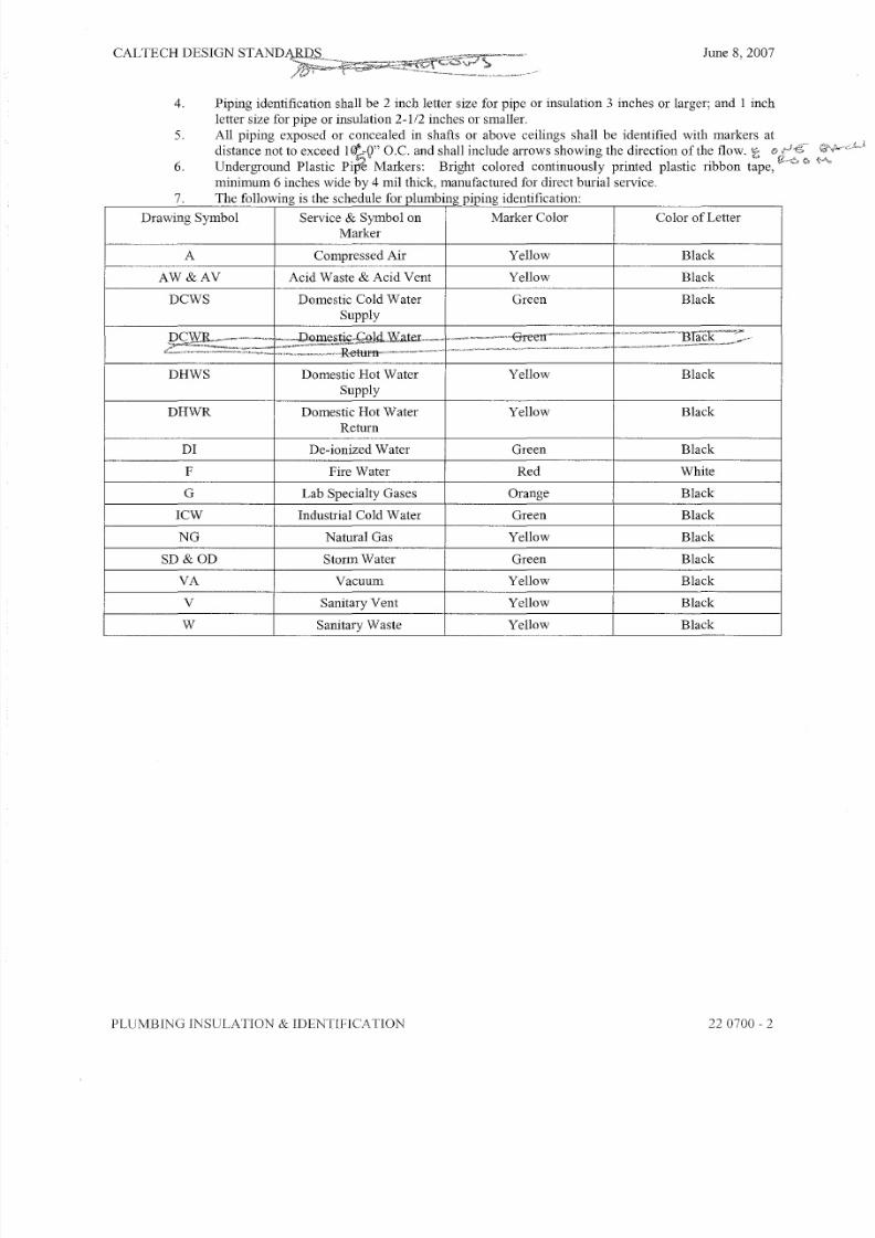
4. Piping identification shall be 2 inch letter size for pipe or insulation 3 inches or larger; and I inch
letter size for pipe or insulation 2-112 inches or smaller.
5. All piping exposed or concealed in shafts or above ceilings shall be identified with markers at
distance not to exceed l < t , - Q " O.C. and shall include arrows showing the direction of the flow. 't;
6. Underground Plastic Pi~ Markers: Bright colored continuously printed plastic ribbon tape,
minimum 6 inches wide by 4 mil thick, manufactured for direct burial service.
7. The following is the schedule for plumbing piping identification:
Drawing Symbol Service & Symbol on Marker Color Color of Letter
Marker
A Compressed Air Yellow Black
AW&AV Acid Waste & Acid Vent Yellow Black
DCWS Domestic Cold Water Green Black
Supply
.DG~R n r"lAW"tf'T " Hlack~"vvH
l}
DHWS Domestic Hot Water Yellow Black
Supply
DHWR Domestic Hot Water Yellow BlackReturn
DI De-ionized Water Green Black
F Fire Water Red White
G Lab Specialty Gases Orange Black
ICW Industrial Cold Water Green Black
NG Natural Gas Yellow Black
SD&OD Storm Water Green Black
VA Vacuum Yellow Black
V Sanitary Vent Yellow Black
W Sanitary Waste Yellow Black
PLUMBING INSULATION & IDENTIFICA TlON 220700 - 2

8/7/2019 Plumbing design guideline_01
http://slidepdf.com/reader/full/plumbing-design-guideline01 4/27
CALTECH DESIGN STANDARDS June 8, 2007
22 1116 - DOMESTIC WATER PIPING
A. General
1. Connect the building to a buried campus water main for normal service. Provide meter, vault, and
line-sized, valved by-pass, and backflow devices. Meter registers should read in cubic feet.
2. Coordinate point-of-connection to the Campus water main and coordinate with Facilities
Management
3. Minimum cover of pipes from fmish grade shall be 36".
4. Provide stand-by water connection from a near-by City main, with provisions for temporary meter
to be placed when needed.
B. Pipes And Pipe Fittings
1. Domestic Water
a. Domestic Water Exterior & Inside Building, below grade
1) Pipes to 5 feet outside the building shall be Type K soft temper copper, ASTM 88.
2) Joints shall be solder type with "sil-fos", or flared type.
3) Fittings shall be wrought copper solder joints, ANSI B 16.22 or brass flared fittings,
ANSI B16.26.
b. Above-grade Hot and Cold Potable Water Piping and Industrial Water-Piping:
1) Seamless copper tubing, Type L, cold drawn, hot temper, ASTM B-88.
2) Exposed to view at plumbing fixtures and finished equipment, satin finish CP brass
pipe with threaded cast bronze fittings.
3) Fittings: Wrought copper solder sweat type, ANSI B16.22 or brass castings, ANSI
B16.18.
2. De-ionized Water Piping
a. Shall be Polypropylene System as manufactured by "George Fisher" Beta Metric Line with
fused joint and fitting connections.
C. Execution
1. Domestic Water Piping:
a. Underground Service Mains:
1) Install concrete anchor blocks or tie-rods on all underground lines at all tees and
elbows to prevent movement when under pressure. Do not use retainer glands. Alltie-rods, clamps, brackets, and bolts shall be galvanized. In addition, coat with
heavy duty bituminastic material.
b. Above-Ground Piping:
1) Run mains as indicated on the Drawings, at evenly pitched 1 i nch in 50 feet.
2) Make allowance for expansion in the installation of all piping so that the usual
variation in temperature will not cause stress at any point. Securely anchor where
necessary to distribute expansion stresses.
3) Arrange system for complete drainage with 314-inch hose valves at low points.
4) Anchor all lines and risers as necessary to prevent noise or vibration when water is
turned on or off.
5) Separately valve each branch and riser. Make all such valves accessible with
approved type panels.
6) Balance, vent, and adjust piping to provide circulation to all fixtures and to preventwater hammer.
DOMESTIC WATER PIPING 22 1116 - 1

8/7/2019 Plumbing design guideline_01
http://slidepdf.com/reader/full/plumbing-design-guideline01 5/27
CAL TECH DESIGN STANDARDS June 8, 2007
22 1119 - DOMESTIC WATER PIPING SPECIALTIES
A. Hose Bibs
1. Hose bibs shall be exposed type for mild climate, with anti-siphon vacuum breaker and anti-
contamination wall faucet, brass finish and with cast iron wheel handle. Vacuum breaker to be
certified to ASSE Standard 1011 and as listed by IAPMO.
2. Unit to be similar to MIFAB MHY-90 and shall be a minimum of%".
B. Water Hammer Arrestors:
1. Water hammer arresters shall be properly sized and located as per recommendations of Plumbing
and Draining Institute (PDI) Standard PDI-EH 201.
2. Water hammer arresters shall comply with ASTM B88, and Type "K" hard drawn copper body,
brass piston and threaded connector. Seal lubricant to be Federal Food and Drug Administration
approved for use in potable water systems.
3. Normal operating pressure is 35 to 250 psig with a maximum surge pressure not to exceed 1500
psig. Arrestor to be fully guaranteed for the entire system life.
4. Shall be installed on all fixtures with quick closing valves and all valves which close with flow of
fluid and on headers serving more than fixture.
5. Acceptable manufacturer is Precision Plumbing Products, Inc. (PPPI), no known equal.
C. Trap Primers:
1. Tramp primers shall be all brass valves with adjustment screw for high or low pressure and shall
be located at least 7" above the trap being served.
2. Tramp primers shall comply with ASSE 1018 and adjustable to lime pressure.
3. Provide trap primer distribution unit when serving more than 1 fixture.
4. Provide access panel for periodic inspection. Entire installation shall be as recommended by the
manufacturer.
5. Tramp primer shall be similar to Precision Plumbing Products, Inc. (PPPI), P-I, or P-2 models.
D. Backflow Preventer:
1. Backflow preventer shall be of the reduced pressure backflow preventer type with two
independent check valves with intermediate relief valve and supplied with shut-off valves and ball
type test cocks.2. Provide backflow preventer with the body size as the line being served for both the City water
supply and the domestic (potable) water system against non-potable substances being forced into
them, or drawn into them during times of less than atmospheric pressure in the water supply
prpmg.
3. Provide backflow preventer on all domestic water services to cooling towers and other pieces of
mechanical equipment requiring water.
4. Provide piped discharge relief drain piping of type DWV copper from backflow preventer to
nearest approved receptor.
5. Backflow protection devices shall be approved by the City of Pasadena, installed in accordance
with the California Plumbing Code and the restrictions, if any, upon which City approval is
contingent.
6. Acceptable manufacturer is Watts.
DOMESTIC WATER PIPING SPECIALTIES 22 1119 - 1

8/7/2019 Plumbing design guideline_01
http://slidepdf.com/reader/full/plumbing-design-guideline01 6/27
CAL'fECH DESIGN STANDARDS June 8, 2007
221123 - DOMESTIC WATER PUMPS
A. Circulating Pumps
1. Circulating pumps shall be for the domestic hot water systems. See Section 22 0000 for Design
Criteria.
2. All parts of pump shall be bronze or stainless construction.
3. Pump shall be installed with shut-off valves and union on each side of the pump with a check
valve in the pump discharge.
4. Pump shall be manufactured by Bell & Gossett, Taco, or equal.
B. Domestic Booster Pumps
1. Unit shall be a triplex system, with one pump for future, completely factory flow tested, variable
speed, constant pressure water booster system.
2. Entire package shall be UL listed.
3. Pumps: End suction, close-coupled, with bronze impeller & replaceable bronze casing wear ring &
single mechanical seal.
4. Motor: Open drip. Proof, NEMA standard, regreaseable ball bearings.
5. Control panel: Pre-wired & tested, NEMA I, UL listed, magnetic starters with overload protection,
through the door disconnect, hand-off automatic switches, pilot lights, fused motor branches,
automatic alternator to select lead. Lag positions of the main pumps. Control circuit transformer,
audible & visual alarm indication & reset button. Include the future pump in the control panel.
6. Hydropneumatic tank: Vertical, ASME with FDA approved bladder, 220 gallons capacity, 125
PSIG, factory mounted and piped with ASME pressure relief valve.
DOMESTIC WATER PUMPS 22 1123 - 1

8/7/2019 Plumbing design guideline_01
http://slidepdf.com/reader/full/plumbing-design-guideline01 7/27
CALTECH DESIGN STANDARDS June 8, 2007
22 1316 - SANITARY WASTE AND VENT PIPING
A. Sanitary Waste and Vent
1. Below Ground:
a. Pipe & fittings: Duriron type "MJ" corrosion resisting cast iron drainage piping for all
below grade piping, regardless of the waste it conveys. Duriron shall conform to ASTM
A518 and A861. Pipe and fittings shall be marked with the collective trademark of the
Cast Iron Soil Pipe Institute.
b. Joints: Mechanical Joint consists of an inner sleeve ofPTFE, surrounded by an outer sleeve
of Neoprene rubber, with the two sleeves are held in place by a 300 series stainless steel
coupling. The two bolt coupling is resistant to corrosion by organic and inorganic acids
and their salts. Duriron "MJ" series.
2. Above Ground:
a. Pipe & fittings: Standard weight cast iron no-hub soil pope conforming to the requirements
of CISPI Standard 310 or ASTM A74. Pipe and fittings shall be marked with the collective
trademark of the Cast Iron Soil Pipe Institute.
b. Joints: No-hub couplings to be type 304 stainless steel, FM Class 1, ASTM C1540 as
manufactured by Husky SD4000 or Clamp-All 125, for the following areas:
1) Over food preparation centers, food serving facilities, food storage areas.
2) Sanitary piping in areas not included in the above areas:
a) CISPI stainless steel bands as manufactured by Anaco, Tyler or equal, where
specified for above grade use only.
B. Sub-Surface or Foundation Drain
1. PVC pipe and fittings, perforated, Class 12454-B (PVC 1120), ASTM D2729; primer, ASTM
F656; solvent cement, ASTM 2564; with polypropylene fabric filter cover.
C. Sewage Ejector and Sump Pump Discharge Piping and Fittings
1. General
a. Piping includes all discharge piping from units to a point of connection where pump
discharge connects to gravity drainage line.
b. "No hub" couplings are not acceptable on any pumped discharge line.
2. Discharge Piping Above Ground:a. Galvanized steel pipe, screwed, Schedule 40.
b. Galvanized steel pipe with grooved ends, Schedule 40.
3. Discharge Piping Below Ground:
a. Ductile iron with mechanical joints.
b. Cast iron with mechanical joints.
4. Fittings:
a. Cast iron screwed drainage fittings.
b. Victaulic "zero-flex" fittings.
c. Galvanized malleable cast iron.
d. "No-hub" type couplings prohibited.
SANITARY WASTE AND VENT PIPING 22 1316 - 1

8/7/2019 Plumbing design guideline_01
http://slidepdf.com/reader/full/plumbing-design-guideline01 8/27
CALTECH DESIGN STANDARDS June 8, 2007
221319 - SANITARY WASTE PIPING SPECIALTIES
A. Drains:
1. Floor Drains:
a. General Purpose Drains (FD-1): Cast iron body, adjustable nickel bronze strainer, bottom
outlet, double drainage flange with weep holes and trap primer connection.
b. Mechanical Room Drain (FD-2): Provide cast iron body with adjustable top and "safe-set"
bucket with trap primer connection.
2. Floor Sinks:
a. Floor sink (Mechanical Rooms): Cast iron flanged receptor with acid resistant coated
interior, nickel bronze rim and secured grate, dome bottom strainer, and trap primer
connection.
b. Floor sink (Roof): Cast iron receptor with solid water dam and cast iron dome bottom
strainer secured with stainless steel vandal-proof screws, and trap primer connection.
B. Fixture Carriers:
1. Wall Hung Water Closets: heavy cast iron fittings, or equal faceplate, foot support, coupling and
mounting trim. Fittings shall be single or double, right or left hand as applicable. Securely bolt
carrier to floor and rigidly connect to waist piping. Finished installation shall be completely self-
supporting and free of finished wall.2. General Purpose Lavatory Carrier shall be concealed type arm carriers.
3. Urinals carrier shall be with one plate support.
C. Cleanouts:
1. Concealed or Exposed in Unfinished Area: ductile iron top assembly, cast iron bodies with anchor
flange, secondary "0" ring test seal and adjustable combined access cover and plug top assembly
with primary gasket seal.
2. Finished Walls: with stainless steel access cover.
3. Finished Floors: satin nickel bronze finish, cast iron bodies with anchor flange, cast iron clamp
ring for water proofing membrane, secondary "0" ring test seal and adjustable combined access
cover and plug top assembly with primary gasket seal.
SANITARY WASTE PIPING SPECIALTIES 221319-1

8/7/2019 Plumbing design guideline_01
http://slidepdf.com/reader/full/plumbing-design-guideline01 9/27
CALTECH DESIGN STANDARDS June 8, 2007
22 1329 - SANITARY SEWERAGE PUMPS
A. Sewage Ejectors
1. Pumps shall be submersible sewage ejectors and shall be driven by a completely sealed electrical
submersible motor with length of cord as required.
2. The motor shall be designed for a Class 1, Group D, Division 1 hazardous location as defined by
the National Electrical Code. The unit shall be listed with Underwriter's laboratories as Class I,
Group D, Division 1 explosion proof for installation in water or sewage. All electrical parts shall
be housed in an air-filled cast iron, watertight enclosure. The enclosure shall be sealed by the use
of "0" rings and shall be rabbet joints with a large overlap. Cable leads shall be epoxy sealed.
The motor shafts shall be stainless steel, impervious to the liquid and waste material being
handled. All external hardware, including the motor nameplate, shall also be made of stainless
steel.
3. Tandem seals, one inside of oil chamber and one outside, shall provide double protection for the
electrical parts. Two moisture sensing probes shall be used to detect any influx of conductive
liquid past the outer seal and provide ample warning of first seal failure.
4. Bearings shall be pre-lubricated at the factory and designed for BI0 life of 15,000 hours. Shaft
extension bearing shall be locked to prevent shaft movement and to take high-trust loads.
5. Motor winding shall have a special Class B insulation system with Class F material extended
motor life. Automatic re-set, normally closed thermal overloads shall be installed in adjacentphases of the motor windings to provide the overheating protection.
6. Lifting eyes shall cast into the motor housing and shall be of adequate strength to lift the entire
pump motor assembly.
7. The impeller shall be of one-piece ASTM A48, Class 30B, close grain cast iron, Chenault design.
The impeller shall be of non-clog design, with large smooth contours, without acute turns, free of
blowholes and imperfections. The large free passages shall be capable of handling solids, fibrous
materials, sludge and other matter normally found in conventional wastewater applications.
a. Single and multi-vane impellers shall be capable of field trimming and balancing to meet
actual site specific conditions. The impeller hub shall be accurately slip fitted and key
driven to the motor shaft. The impeller shall be securely attached to the shaft by means of
a locking washer and impeller screw of AISI-304 stainless steel.
b. Coating of the impeller to show improved or better efficiency on published or test curves
shall not be acceptable. All pump performance data submitted shall be based on uncoatedimpellers. Any attempts to alter the pump performance by coating the impeller shall not be
acceptable.
8. Sewage ejectors shall be duplex, non-clog wastewater system with slide rail lift-out feature. The
system shall include all valving, piping, access hatches, level sensors and motor controls necessary
to provide the University with a fully operational system.
9. Controls:
a. Control panel shall be pre-wired and factory tested and shall carry Underwriters
Laboratories label.
b. Level sensors shall be of the bulb type designed for wet well application, equipped with
cord as required by field conditions.
c. Panel shall have dry contact for each pump to indicate on condition and one for high water
alarm for remote monitoring by BMS.
10. Rail System: The design of the rail disconnects system shall permit the easy removal and
reinstallation of each pumping unit from the wet well for inspection or service without
disconnecting or disturbing the discharge piping.
a. Each pump shall be provided with a guide rail bracket requiring two guide rails to insure
proper alignment and stability during installation or removal of the pump unit.
b. Each guide bracket shall have non-sparkling material at the point of contact with the guide
rails to prevent spark ignition of explosive wet well gases during pump installation or
removal.
c. A Class 30B, cast iron discharge elbow for each pump shall be securely mounted to the wet
well floor. The receiving end of the elbow shall be of non-sparking material. The pump
SANITARY SEWERAGE PUMPS 22 1329 - 1

8/7/2019 Plumbing design guideline_01
http://slidepdf.com/reader/full/plumbing-design-guideline01 10/27
CALTECH DESIGN STANDARDS June 8, 2007
discharge shall be fitted with a resilient seal which, when mated with the discharge elbow,
provides a positive hydraulic seal for maximum pumping efficiency.
d. The guide rails of Schedule 40 stainless steel pipe shall be furnished and installed, and shall
be securely supported, top and bottom, by guide rail support brackets furnished by the
pump manufacturer.
e. The lower guide rail bracket shall be securely mounted to the wet well floor and properly
aligned.
f. The guide rail disconnect system once installed, shall provide stable, three point support ofthe pumping unit. Designs which require that the entire weight of the pumps and the motor
be supported from the discharge flange will not be considered acceptable.
g. The entire guide rail disconnect pumping system shall be listed and labeled by a nationally
recognized testing laboratory such as Underwriter's Laboratory as suitable for operation in
a Class 1,Division 1, Group D hazardous location.
11. Lifting Device: Each pumping unit shall be provided with a lifting cable of stainless steel
construction, and of adequate strength to support the live load weight of the entire pump and
motor assembly.
12. Access Hatches: The pump system access hatch and frame shall be of single door design, gas
tight construction and fabricated of aluminum material. The access hatch shall be rated at 150 psf
live load for pedestrian traffic. The access hatch shall be hinged and provided with a hasp and
staple locking device as standard, and with a non-skid surface in the closed position. Accessories
provided with the hatch shall be upper guide rail support bracket, level sensor, power cable holderbracket, lifting cable hooks and a locking bar to secure the hatch in the open position.
SANITARY SEWERAGE PUMPS 221329-2

8/7/2019 Plumbing design guideline_01
http://slidepdf.com/reader/full/plumbing-design-guideline01 11/27
CALTECH DESIGN STANDARDS June 8, 2007
221413 - STORM DRAINAGE PIPE AND PIPE FITTINGS
A. Pipe and Pipe Fittings
1. Below Ground:
a. Pipe & Fittings: Service weight cast iron or no-hub type soil pipe conforming to the
requirements of CISPI Standard 301 or ASTM A74. Pipe and fittings shall be marked with
the collective trademark of the Cast Iron Soil Pipe Institute.
b. Joints: Couplings shall conform to the requirements of ASTM C1540, FM 1680 and shall
be heavy duty type 304 stainless steel shielded couplings with a 28 Gauge shield, Husky
SD4000 or equal.
c. Alternate Material, where applicable and subject to approval by local authorities having
jurisdictions:
1) Piping shall be PVC DWV conforming to ASTM D2665-2004a.
2) Fittings shall be PVC DWV conforming to ASTM 3311-2002
d. Alternate Material, where piping is under Civil Work and is not limited by the California
Plumbing Code, Caltech will allow the use of RCP.
2. Above Ground:
a. Pipe & Fittings: Standard weight cast iron no-hub type soil pipe conforming to the
requirements of CISPI Standard 310 or ASTM A74. Pipe and fittings shall be marked with
the collective trademark of the Cast Iron Soil Pipe Institute.b. Joints: No-hub couplings to be type 304 stainless steel, FM Class 1, ASTM C 1540 as
manufactured by Husky SD 4000 or Clamp-All 125.
STORM DRAINAGE PIPE AND PIPE FITTINGS 22 1413 - 1

8/7/2019 Plumbing design guideline_01
http://slidepdf.com/reader/full/plumbing-design-guideline01 12/27
CAL TECH DESIGN STANDARDS June 8, 2007
22 1423 - STORM DRAINAGE PIPING SPECIALTIES
A. DRAINS
1. Roof Drains: Coated cast iron body, with anchor flange, sump receiver, underdeck clamp,
extension if required, large steel dome self-locking strainer, clamp ring with integral gravel stop
and deck clamp assembly.
2. Overflow Drains: Same as RD-1 except drain to be installed with inlet 2" water dam.
3. Overflow drain downspout nozzle shall be two piece, stainless steel downspout nozzle with anchor
flange and pre drilled counter sunk mounting holes.
STORM DRAINAGE PIPING SPECIALTIES 22 1423 - 1

8/7/2019 Plumbing design guideline_01
http://slidepdf.com/reader/full/plumbing-design-guideline01 13/27
CALTECH DESIGN STANDARDS June 8, 2007
221429 - SUMP PUMPS
A. SUMP PUMPS
1. Pumps shall be submersible duplex type sump pumps, quick removal type and shall be driven by a
completely sealed electrical submersible motor with length of cord as required.
2. The motor shall be designed for a Class 1, Group D, Division 1 hazardous location as defined by
the National Electrical Code. The unit shall be listed with Underwriter's laboratories as Class I,
Group D, Division 1 explosion proof for installation in water or sewage. All electrical parts shall
be housed in an air-filled cast iron, watertight enclosure. The enclosure shall be sealed by the use
of "0" rings and shall be rabbet joints with a large overlap. Cable leads shall be epoxy sealed.
The motor shafts shall be stainless steel, impervious to the liquid and waste material being
handled. All external hardware, including the motor nameplate, shall also be made of stainless
steel.
3. Tandem seals, one inside of oil chamber and one outside, shall provide double protection for the
electrical parts. Two moisture sensing probes shall be used to detect any influx of conductive
liquid past the outer seal and provide ample warning of first seal failure.
4. Bearings shall be pre-lubricated at the factory and designed for B10 life of 15,000 hours. Shaft
extension bearing shall be locked to prevent shaft movement and to take high-trust loads.
5. Motor winding shall have a special Class B insulation system with Class F material extended
motor life. Automatic re-set, normally closed thermal overloads shall be installed in adjacent
phases of the motor windings to provide the overheating protection.
6. Lifting eyes shall cast into the motor housing and shall be of adequate strength to lift the entire
pump motor assembly.
7. The impeller shall be of one-piece ASTM A48, Class 30B, close grain cast iron, Chenault design.
The impeller shall be of non-clog design, with large smooth contours, without acute turns, free of
blowholes and imperfections. The large free passages shall be capable of handling solids, fibrous
materials, sludge and other matter normally found in conventional wastewater applications.
a. Single and multi-vane impellers shall be capable of field trimming and balancing to meet
actual site specific conditions. The impeller hub shall be accurately slip fitted and key
driven to the motor shaft. The impeller shall be securely attached to the shaft by means of
a locking washer and impeller screw of AISI-304 stainless steel.
b. Coating of the impeller to show improved or better efficiency on published or test curves
shall not be acceptable. All pump performance data submitted shall be based on uncoatedimpellers. Any attempts to alter the pump performance by coating the impeller shall not be
acceptable.
8. Controls:
a. Control panel shall be pre-wired and factory tested and shall carry Underwriters
Laboratories label.
b. Level sensors shall be of the bulb type designed for wet well application, equipped with
cord as required by field conditions.
c. Panel shall have dry contact for each pump to indicate on condition and one for high water
alarm for remote monitoring by BMS.
9. Rail System: The design of the rail disconnects system shall permit the easy removal and
reinstallation of each pumping unit from the wet well for inspection or service without
disconnecting or disturbing the discharge piping.
a. Each pump shall be provided with a guide rail bracket requiring two guide rails to insureproper alignment and stability during installation or removal of the pump unit.
b. Each guide bracket shall have non-sparkling material at the point of contact with the guide
rails to prevent spark ignition of explosive wet well gases during pump installation or
removal.
c. A Class 30B, cast iron discharge elbow for each pump shall be securely mounted to the wet
well floor. The receiving end of the elbow shall be of non-sparking material. The pump
discharge shall be fitted with a resilient seal which, when mated with the discharge elbow,
provides a positive hydraulic seal for maximum pumping efficiency.
SUMP PUMPS 22 1429 - I
8/7/2019 Plumbing design guideline_01
http://slidepdf.com/reader/full/plumbing-design-guideline01 14/27
CALTECH DESIGN STANDARDS June 8,2007
d. The guide rails of Schedule 40 stainless steel pipe shall be furnished and installed, and shall
be securely supported, top and bottom, by guide rail support brackets furnished by the
pump manufacturer.
e. The lower guide rail bracket shall be securely mounted to the wet well floor and properly
aligned.
f. The guide rail disconnect system once installed, shall provide stable, three point support of
the pumping unit. Designs which require that the entire weight of the pumps and the motor
be supported from the discharge flange will not be considered acceptable.
g. The entire guide rail disconnect pumping system shall be listed and labeled by a nationally
recognized testing laboratory such as Underwriter's Laboratory as suitable for operation in
a Class 1, Division 1, Group D hazardous location.
10. Lifting Device: Each pumping unit shall be provided with a lifting cable of stainless steel
construction, and of adequate strength to support the live load weight of the entire pump and
motor assembly.
11. Access Hatches: The pump system access hatch and frame shall be of single door design, gas
tight construction and fabricated of aluminum material. The access hatch shall be rated at 150 psf
live load for pedestrian traffic. The access hatch shall be hinged and provided with a hasp and
staple locking device as standard, and with a non-skid surface in the closed position. Accessories
provided with the hatch shall be upper guide rail support bracket, level sensor, power cable holder
bracket, lifting cable hooks and a locking bar to secure the hatch in the open position.
SUMP PUMPS 22 1429 - 2
8/7/2019 Plumbing design guideline_01
http://slidepdf.com/reader/full/plumbing-design-guideline01 15/27
CALTECH DESIGN STANDARDS June 8, 2007
22 3000 - PLUMBING EQUIPMENT
A. Water Heaters
1. Water heater shall be constructed and stamped in accordance with ASME Code. The water heater
will be national Board registered for a working pressure of 150 psig.
2. Heater shall be mounted on a steel support skid.
B. Water Softeners
1. Water Softener shall be service exchange softener system, supplied by Caltech's Vendor.
2. Feed water piping to include pressure regulating valve to maintain maximum of 75 psi feed
pressure to softener units.
3. Pressure gauges to be 316 stainless steel, liquid filled gauges. 0 -100 psi, W' base.
4. Piping Manifold
a. All isolation valves 2" and smaller to be Nibco T5954 ball valves. Brass body. Stainless
steel ball. 3 piece valve
b. All valves 2 W' and larger to be Victaulic Butterfly valve Model 608. Grooved end valve.
Double seal disk design. Bronze body. EPDM seal. Bronze disk. Point of connection for
US Filter to be companion flange with 3" FPT connection.
c. All sample valves to be Nibco 1 1 4 " ball valve. Brass body and stainless steel ball.
d. Y strainer to include 30 mesh or smaller
5. Supply and install camlocks connections for piping manifold and inlet/outlet hoses for service
exchange softeners
6. Supply and install Hardness monitors indoors, within 20 feet of service exchange softeners.
7. Location for hardness monitors must include an outlet within 3 feet of the monitors and a drain,
capable of handling up to 1 liter/minute
8. Supply and install W' copper tubing from piping manifold to harness monitors. Terminate tubing
within 2 feet of monitor, with isolation valve. Vendor will make final connections to monitors and
provide system startup.
9. Provide all required material, labor, and permits to build piping manifold and install hardness
monitors.
10. Provide installation supervision and system startup.
PLUMBING EQUIPMENT 223000 - 1

8/7/2019 Plumbing design guideline_01
http://slidepdf.com/reader/full/plumbing-design-guideline01 16/27
CALTECH DESIGN STANDARDS June 8, 2007
22 4000 - PLUMBING FIXTURES
A. Caltech Preferred Vendor list for Plumbing Fixtures. See also individual sections of the guidelines for
more details on model numbers
Equipment Type Caltech preferred first listed (if Caltech acceptable alternates
preference)Water Closet Wall Mounted American Standard
Wall Mounted WC Sloan Royal Optima Smooth
Flushometer Model 1101111
Water Closet Floor Mounted American Standard Madera 17H
Elongated Flush Valve Toilet
Floor Mounted WC Sloan Royal Optima Smooth
Flushometer Model 110/111
Urinal American Standard Maybrook
Urinal
Urinal Flushometer Sloan Royal Optima Smooth
Model 186
Lavatory American Standard Boulevard
Under Counter Sink
Faucet Sloan Optima i.q. EAF-I50
1. Water Closet
a. Fixture: Vitreous China, siphon jet action, elongated bowl, wall mounted, flush valve, 1.6
gallons per flush.
b. Valve: Quiet, exposed, diaphragm type, chrome plated closet flushometer valve, 1-1/2" top
spud, battery powered, with water saving feature, quiet action, vacuum breaker,
screwdriver stop, 1.6 gpf, and with mechanical manual override, Sloan Royal Optima
Smooth Model 110/111 (no known equal).c. Seat: Heavy duty white molded plastic with stainless steel hinge with stop, open front,
without cover.
d. See attached sheet P6a & P6b for Caltech preferred model and manufacturer
2. Water Closet (HDC):
a. Fixture: Vitreous China, siphon jet action, elongated bowl, wall mounted, flush valve, 1.6
gallons per flush, ADA compliant.
b. Valve: Quiet, exposed, diaphragm type, chrome plated closet flushometer valve, 1-112" top
spud, battery powered, with water saving feature, quiet action, vacuum breaker,
screwdriver stop, 1.6 gpf, and with mechanical manual override, Sloan Royal Optima
Smooth Model 1101111 (no known equal).
c. Seat: Heavy duty white molded plastic with stainless steel hinge with stop, open front,
without cover.
d. See attached sheet P6a & P6b for Caltech preferred model and manufacturer
3. Water Closet (Floor mounted):
a. Fixture: Vitreous China, siphon jet action, elongated bowl, floor mounted, flush valve, 1.6
gallons per flush.
b. Valve: Quiet, exposed, diaphragm type, chrome plated closet flushometer valve, 1-1/2" top
spud, battery powered, with water saving feature, quiet action, vacuum breaker,
screwdriver stop, l.6 gpf, and with mechanical manual override, Sloan Royal Optima
Smooth Model 1101111 (no known equal).
c. Seat: Heavy duty white molded plastic with stainless steel hinge with stop, open front,
without cover.
PLUMBING FIXTURES 224000 - 1

8/7/2019 Plumbing design guideline_01
http://slidepdf.com/reader/full/plumbing-design-guideline01 17/27
CALTECH DESIGN STANDARDS June 8, 2007
d. See attached sheet PI for Caltech preferred model and manufacturer
4. Urinal:
a. Fixture: Vitreous china, siphon jet with flushing rim, I" top spud, wall hung and with 1.0
gallons per flush, ADA compliant.
b. Valve: Quiet, exposed, diaphragm type, chrome plated urinal flushometer %" top spud,
battery powered, sensor activated, vacuum breaker, screwdriver stop, 1.0 gpf flush,
mechanical manual override, Sloan Royal Optima Smooth Model 186 (no known equal).
c. See attached sheet P2, P5a and 5b for Caltech preferred models and manufacturers
5. Lavatory:
a. Fixture: White, vitreous china, undercounter mount, front overflow, with 0.5 GPM flow
restrictor.
b. Supply: Deck mounted, with 4" center to center, Y. turn washerless ceramic disc valve
cartridges, cast brass spout and all brass drain body.
c. Stops" 1 2 " solid flexible tube riser with 1 2 " lose key angle valve with replaceable cartridge,
lockshield.
d. Trap: 1-114" x 1-1/2" cast brass adjustable P-trap with IPS brass waste to wall. Provide
offset for ADA compliant lavatories.
e. See attached sheet P3 for Caltech preferred model and manufacturer
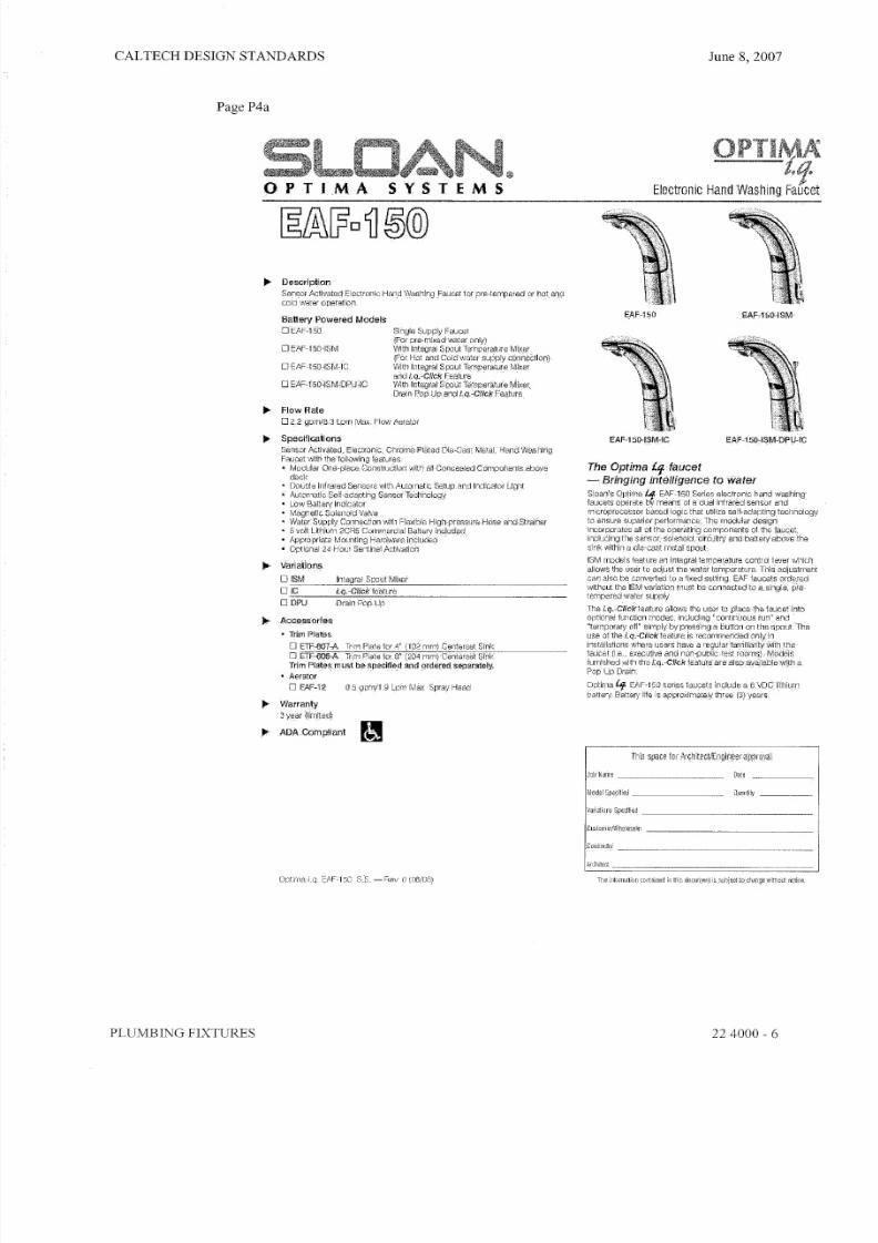
6. Faucet:
a. Fixture: Sensor activated electronic hand-washing faucet
b. Features: battery operated, single-supply faucet
c. See attached sheet P4a and 4b for Caltech preferred model and manufacturer
7. Sink (Double-compartment):
a. Fixture: Double compartment sink, 18 gauge, Type 304 nickel bearing stainless steel, self
rimming, with dishwasher hook-up and with disposer, with number of holes as required.
b. Supply: Single lever kitchen faucet with hose and spray, with ceramic control components,
handle limit stop, and red/blue indicators, 8-3/4" swing spout with aerator, 3/8" supplies,
8" centers, metal construction, polished chrome finished.
c. Disposer: Y z HP motor, continuous feed, galvanized steel grinding elements with two
stainless steel 3600 swivel lugs and provided with self-service wrench.
8. Sink (Single compartment):
a. Fixture (Non- ADA Compliant): Countertop, single compartment sink, 18 gauge, Type 304
nickel bearing stainless steel, self rimming, 10" deep and with number of holes as required.
b. Fixture (ADA Compliant): Single compartment sink, 18 gauge, Type 304 nickel bearingstainless steel, self rimming, 6-112" deep and with number of holes as required.
c. Supply: Blade handle faucet with ceramic control components, handle limit stop, vandal
resistant aerator, 3/8" supplies, 4" centers, metal construction, polished chrome finished.
9. Service Sink (SS-l):
a. Fixture: Angle terrazzo mop receptors or equal, with 4" high inside shoulder and 1-3/4"
wide. Stainless steel protective cap to be cast integral on all four exposed sides. Drain
body shall be brass, cast integral and shall provide for a non-caulked connection not less
than one inch deep to a 3" drain pipe.
b. Supply: With rigid vacuum breaker spout, %" hose thread outlet, pail hook and wall brace
adjustable integral stop supply arms chrome finish.
PLUMBING FIXTURES 224000 - 2

8/7/2019 Plumbing design guideline_01
http://slidepdf.com/reader/full/plumbing-design-guideline01 18/27
CALTECH DESIGN STANDARDS
Page PI
PLUMBING FIXTURES
1 ~ l iM t s ~ 1~ BARRIER FREE
MADERA ™ 17"H ELONGATED 10" ROUGH
• Vit reous china
• Low-consumption (6.0 Lplil.6 gpf)
~ 10 " rouqninq.in' 17" rim height
• Elongated bowl
• Direct- fed siphon [etaction
. . Ful ly glazed 2 " b al lp as s t ra pw a y
• 11" x 13" water surface area
• 1-1/2" top spud
• 2 bolt caps
'100%faclory f lush tes ted
o 3043.102 Top spud
o 3043.156 Top spud with slotted rim for
bedpan ho lding (wh ite only)
Nominal Dimensions:
765 x 3S1 x 43Smm (30-1/S" x 15" x 17-1/4")
Recommended working pressure--between
25 psi at valve when flushing and SOpsi
sialic
Fixture onfy, less seat and boll caps
Compliance Certi ficaticms -
Meets or Exceeds the Fol lowing Specifications:
• ASME A11219.2M (and 19.6M) for Vitreous
China Fixtures - Ihc!ud",$ Flush Performance.
Bal l Pass Diameter, Trap.Seal Depth and
all Dimensions
To 8e Specified
o Color: 0 White 0 Bone 0 Silver 0 Black
OShell
o Seat: Olsonlte #95 open front seat less
cover
o Seat: Church #9500C open front seat less
Gover
o AlternateSeat:
o Flush Valve: Sloan Royal #111
o Alternate Flush Valve:
rrl•~hen installedso tap of seetis 432 to 483mm(17" 1.0 19"jfiQinthe
L Q : J f in is he d r lc cr .
. MEETS THEAMERICAN DISABjLlTIES ACT GUIDELINES ANDANSI A117~1
REqUIREMEt:JTS FORACCESSIBLEAND USEABLE BUILDING FACILITIES-
CHE;CKLOCAL CODES.
June 8, 2007
"A.DERA ™ 1'7"8ELOrU':ATED FLUSH VALVE TOILET
VITREOUS CHINA
I ' N ,P .10R I ' C .W_T: SUpPLY
TO FLUSHVALVE\
~~12'",", I I(4,~141 ~ nOl11m
I (283/4)
" ' " ' " ' E(15)
I - I 1'2SPUD
NOTES:
PRODUCT 3043_lD2 SHOWN, 3043,J56 SAME AS.EXCEP-TWITH SLODEDA IM FORBEDPANHOLDING
T HIS T OIL ET .I S D ES lG NE D T O R OU GH · I N A T A M IN IM Ulv lD lM EN SIQ N O F2 54 MM ( .1 0")
FROM RNISHED,WALL TO en , OF OUTLET.TO CQI"lPLYWIlHAREA' CODE GOVERNING THE ,HEIGHT OF VACUUM BREAKER ON
FLUSH VALVE. THE,PLUMBERMUSTVERIFYDHAENSIONS SHOWN.FOR SUPPLY ROUGH·II'JG
FLUSHVAL~E ~OTINCLUDED AND MUST~E ORDERED SEPAFlATELYIMPORTANT: Dime nsions. of tmures ara nominal and may Veil),with in lhe rame.ct lol8' lances
established b\' A N SI S ta n da r d A 1 12 .1 9 .2 ,
T I18-S8r reasuremems are s ub je ct .i o c ha nq e. or c an ce ll at lo n N o reeponslbnnyjs a ss um ed t or u se
of superseded cr-voided paqes .
SPS3043
Revised 4[96 ( c) ·1998 Ameri can Standard Inc .
224000 - 3

8/7/2019 Plumbing design guideline_01
http://slidepdf.com/reader/full/plumbing-design-guideline01 19/27
CALTECH DESIGN STANDARDS
Page P2
PLUMBING FIXTURES
1 ~ · . S b w b n l I
June 8, 2007
M A Y B R O O K ™
URINAL
M il . ' r' BR OO f< ;UR I NA L
VrTREOUS CHlt'~A
• \~T80LlSchina
• tow-co nsurnpfio n (3,8. Lpfl1 .0 gpf)
• RUsting rim
• Wa:;luut flush a::ti,jn
•In t e ' t l r a I stra i re r• . :?.'4"i nlet sp iLl
• 0 utlet sp 00 with 1-112" tu I:i ngtailpiece
• Wall hanger
• R:.;tLr'e any·liteetoANSlflL5nll"quireroentoatO;7.p
1D OPF
o 6581,0 15 To p E PO O
t~om in a I · ' bime n sio n o:324)( 324:( 457mm
012-; ), '4 " x 12-3 /4") ( 18 .' ,
REO:lmme nood wor ting preEsure - between
a)psi at'fsl'fe when flLlShing and a:Jpsi ststic:
CcrJ1pli.~me c;.;,rtifi , : ,~ t j o :' rG .
Meets or Exceedsth.e FdlowingSpeQificaticns:
• ASMEA 1 12 ,. 19 .: Uo rV ilI BO u l> c nm a F i: >: tJ re s-
incuues FluSn PerWmmc.e, SBiIPass.
Ciame'er, 'rrBp SeBi Oep1] ano.an [irn~n:;jons
ToSe Spedlied
o CQlor:O Wllite 0 sone 0 SiI 'IEW
OShell O.6IElOk
o FIUsnVBI'Ie: Sloan ROyBi18iH
o Altemahe FlusnVBI~B:
o .p. 'rrap:
UW.t:.'::
* D~~51OJ .I~~O"'J.i r"CoR.LOQl,l1~ 'O"' ' 'P '' T R t lr P 1!"5U'h~.
· P "i Rt Io P . .. J. lD I "U J !!H~jI,U.'e::J.lOTIJ.lCLU[]eI1 L l t J . l D ~u.n!!e::O R DI !: R ~ ~"'R"'"Tn.~·.
PR . ':ifo'1[]1! ~lj f" lI l . . .1! : RI ! J l . U" ' : ' R ~~TI '"OR t lr u . "'lI.ll!ru P P ' : 4 1 "l : I ' .
I~P' : IR"" 'J .lT: tJl'H 11III• • r .r lt bl "l nJi l 1 11 "1 l1 li 1. 1' nlr rllrnl111 tH.nl tI:.•, I I" 1 " 11 1tilr
...rIllllll'M~ .rjl,l-I~~'~Il~ ";11L11,L
" 'J H . . nnn N.,.nlr'lri·nllf:lE±1::Ii cil.!ltiucn C II I 1 .1 1 , .1-11Pi'I'Jllililllf,trlrlmnt"l'ir."
•.h''III ...... ' ..~.-rflllIHiI'l ... r.
224000 - 4

8/7/2019 Plumbing design guideline_01
http://slidepdf.com/reader/full/plumbing-design-guideline01 20/27
CALTECH DESIGN STANDARDS
Page P3
PLUMBING FIXTURES
BOULEVARDTM UNDERCOUNTER SINK
• Rectangular under mount sink with unique
tapered interior bowl
• Made from vitreous china
• Unglazed rim
• Front overflow
• Supp lied with mount ing k it (047194-0070A)
and template
o 0610.000 Unglazed Him
514X406mm
(20-1/4" x 16")
Bowl S.ize:
432mm (17") wide
330m01 (13") front to back152mm (6") deep
Compliance Certifications -
Meets or Exceeds theFollowing Specifications:
• ASME A1 l2 .1 9 .2M for
V it reous China Fix tu res
• CNJlCSA 845 series
I~6~~o~pecitied: _ Io Faucet*:
o Faucet Finish:
o Suppl ies:
[ _ _ _ _ o1~-114"T~rap: __
" 'See fauce t sec ti on -for ado it loua l model s ava il ab le
© 2 00 6 Amer ica n St and ar d I nc.
June 8, 2007
80ULEVARDTMUNDERCOUNTER SINK
VITREOUS CHINA
.DETAIL OF MOUNTING CLIP(KIT No.47194.,Q010A)
NOTES:
WE RECOMMEND USING BASI N AS A TEMPLATE TO I JETERMINEPP.OPER CONTOUR. CUT COUNTERTOP aSMM (1·1/2") INSIDE BASINCONTOUR.
* DIMENSION~'; SHc)Vm FOR LOCATioN OFSljPPLIEO ANlJ "P" TRAP ARESUGGESTED.
'f UNDERCOUNTER MOUNTING KI T SUPPLIED WITH SINK.FITTINGS NOT INCLUDED WITH FITXTURE AND MUST BE ORDEREDSEPARATELY.
SEr,Ur, G COMPOUND SUPPliED BY OTHERS.
IMPORTANT: D imen si on s o f f ix tur es ar e nomi nal -an d ! hay va ry within the
rangeof tcleranoesestabllshedbyANSI StandardA112.19:2:These measur emen ts a re s ubj ec t t o c han ge or c an cell at io n. No r esp ons ibi li tyis assumed f or lise of superseded or voided pages,
J45
Revi sed 5/06
224000 - 5
8/7/2019 Plumbing design guideline_01
http://slidepdf.com/reader/full/plumbing-design-guideline01 21/27
CALTECH DESIGN STANDARDS
Page P4a
PLUMBING FIXTURES
OPT I .MA®
SYSTEMS E l e c t r o n i c Hand W a S h i n g Faucet
.. Description
Sensor Activateq,Electronic Hand Washing Faucet ior pre-terrpered or hotanrr
coldwater operation
Battery Powered Models
DEAF-15b SingleSupply faucet(For pre-mixedwater only)
V~th Integral spout Temperature Mix~t(Fat Hot and Cold water supply connection)W it h I nt eg ra l , sp ou t rernp~rfjturei \ :1: ikerand i.q.~CJick~e~tur8
VVlth.lntegraJ'.SpoutTe 01peratureMi)(er ,Drain Pop)Jpand i.q.-Clic!<Fegture
o EAF-150 'ISNI
DEAF-150- ISM-DPU- IC
.. Flow Rate
o 2_,2"gpm/8,3 l.prn Max. Ftow Aerator
II > Specifications
Sensor Ac t iva ted , E lec t rcn ic, ChrdmeoPlated'Die>-Cast Metal,-Hand Wasllirig
Fauce t \A~th the ' fo I lQWingfea tu resModular' One-pl ece.Ccnstructlon \ M i t h - all Concealed Comocnenrsabcva
II > Variations
D ISM
DIG
DDPU
Inte(jra l S p o u t · J I J 1 t l C _ e f
i.q. ·Click leetlJre
Drain Pop_Up
II > AGGl!ssorii~s
Trim Plates
o E TF -ro ?c A T nrn P la !e l or 4 ·' (1 02 mOl) Gen te l "e ! S ink
o ETF- t lOO-A Tr i .rnPla te tDIS' (204 ml l1 )Gen te rse t SinkTrim Plate~rnust heapecltled and orderedseparately;
Aerator
n EAF-12 as ~ JP h1 /1 , 9 L pn Y M e :, (· S pr ay - H e ad
II > ADACornplianl P I
June 8, 2007
EAF-1S0 EAF-150·ISM
The Optima if faucet
~ Bringing intelligence to Water
Sloan'~ Qptirna· ' : ' I . . .EAF~l50Series elsctronlc hand washj~gf a u ce t s o p e ra t e b\;- means . · 0 1 a d ua l i ni ra r, e d s e n so r a n dmicroprocessor based logic'that utilize self,.adaptingtecilnoiogy
~Qensure superfor _petiqrrnance: Themodular design
Incorporat13 sall.tJ1the ope ra t ing c9~ponents- o f t he ip(jcet,Includjng the .sensor; sol enord,: :c ircu!r:yandbatteN'abov'e 'the81nk , , ;t hi n a dle-cpst rnetalspeut
Drain'.
QPtimai-r EAF-150 s e r ie s l a u ce t s include
battery Ba t te n ! l if e i s a p p r o x ima te ly t h re e - ( 3 )
r il i s s p a c e
JD b N : : J r j1 8 ~
MDdelSpadfilld _ Q _ ll " ln li tv _
224000 - 6

8/7/2019 Plumbing design guideline_01
http://slidepdf.com/reader/full/plumbing-design-guideline01 22/27
CALTECH DESIGN STANDARDS
Page P4b
I--IandWashing Faucet for pre-tempered or
... Flow Rate02,2 gprn/8.3 l.pmviax. FlowAerator
ELECTRICAL SPECIFICATIONS
II > Control Circuit ...
6VDC~ includes Auto 'Set
1 1a ng 8 A dj us tm en t a nd Low
Ba t te r : ./ ind ica to r LED
II > Sensor Range
Nominal:
4" - 5" (102 nlml 2/ 1 1 1 1 n )
Faucet Adaptive Self,
adjustment Range:2 " ~14" (51 rrm ~'~5.6tnm)
nominal
Power Supply
6 VDC ulh ium 2CR5 battery .
A pp ro xim ate 3 Y 8H f life
... Time Out Setting
2 m in ut es - - Ma x imum t ir r. e t a uc e t w d l
run eontinaousdetect'on(except
for models that are otherwise
set cqtltinuousl'Ufl).
i. 'f-9!i¢k FEATLJRE
The i. a-cnc« is a
t h a t a I lO \ J \. I s, t h e
Continuous Run;
Adjustment
B eca use the u se , o f the l.q.~Cfickfea.ture r e qu i re s f am i li a ri TY w i th ihe faucet,
thiS featUr~isnQlreCqmmended , fo r f~ucets,intended. to r -use .by the ~eneral
puqUc.m,e i ;Q<9f ic l f i s i d e a! f o r u s e l ri .h o s ni ta l rooms, ~xecutiywresi roomsa nd o th er , lo qa t!Q l1 s W h f3 :t8 th e p rr na ry u se r h as : re gu l;3 r: Qo nta ct w ith th e
p roduc t .
ROUGH-IN
EAF-150Faucet s wit h Single Line Water Supply
OPERATIONA s 1 1 \,
June 8, 2007
EAF-150-ISM, EAF·150-ISM·ICANDEAF-150-ISM-DPU-ICFaucets with Hot and Co ld Water Supply
three
T r i m
TrimPtetes must bespeclfled and ordered
separately:
ETF-607·A
Trim PlaJeror 4" (102 mOl)
Centerset Sink
ETF-608-A
(204 mm )
C o p yr ig h t© 2 0 0 6 S lo an V a lv e C or np :: :. ny
S LO A N V A L V E C O M P A N Y • 1 0 5 U O S EY M O U R .A V E N U E • F R A N K L I N P A R K , I L 6 0 13 1P ho ne : 1 -S 0 0, g- VALVE -9 o r 1 -3 4 7-6 7 1- 43 0 0· F ax HOO- 44 7 -S 3 29 Q r 1 - 84H 71 -4 ~ 80 • h ltP :! IWWw ; sl oa l1 v~ lv e .cOI ll
PLUMBING FIXTURES
Printt idintheU's.A O p t im a i :q ,E A F -1 5 0 8 ,S . - .~ H e '' (O { ,0 8 /0 G }
224000 - 7

8/7/2019 Plumbing design guideline_01
http://slidepdf.com/reader/full/plumbing-design-guideline01 23/27
CALTECH DESIGN STANDARDS
Page Sa
June 8, 2007
. .. Descr ip tionE xp os ed , B at te ry P ow er ed , S en so r A ct iv ate d, R oy al ' O pt im a' S M OO TH '·
U ri na l F lu s hom et sr f or % " t op s pu d u ri na ls ,
... Flush CycleoMode l 186 Wa te r S av er ( 1, 5 gpf /5 ] l Il f)
oM od eL 1 86 -1 _0 L ow C on su mp tio n ( 1 ,0 9 pf /S ,B L pf )
oM ode l 18 6,Q ,5 (0 5 g pllt9 L pf)
. .. SpecificationsQ ui et , E xp os ed , O ia ph ra g mT yp e, C hr om e P la te d U rin al F lu sh om et er w it h
t he f ol lo w in g f ea tu re s:
Flushometer
• P ER ME X" S ynth etic R Ub be r D ia ph ra gm w ith D ua l F ilte re d F ix ed B yp ass
• A DA C om plia nt M eta l O scilla ting N on -H old -O pe n H and le w ith T rip le S ea l
H a nd le P a ck in g
• % " I PS , S cr ew dr iv er B ak -C he k' · A ng le S to p
• F re e S pinn ing V an da l R es is ta nt S to p C ap• A dj us ta ble T ai lp ie ce
• H ig h B ac k P re ss ur e v ao uc m B re ak er F lu sh C on ne ct io n w it hO nB -p ;e ce
B otto m H ex C ou plin g N ut
• S pud Co upling a nd F la ng e fo r%" T op S pu d
• S we at S old er A da pte r w /C ov er T ub e a nd C ast W a ll F la ng e w lS et S cre w
• H ig h C op pe r, L oW Z in c B ra ss C as ti ng s f or D ez ln cif ic at io n R es is ta nc e
• N on -H old-O pe n H an dle , F ix ed M ete rin g B yp as s a nd N o E xte rna l V olu me
Ad ju s tm e nt t o E n su re Wa te r C on se rv a ti on
• F lu sh A ccu ra cy C ontro lle d b y C ID '" T e C h i l o l o g y
• D ia ph ra gm , H an dle P ack in g, S tO PSeatand V ac uu m B re ak er m ol de d
fro m P ER ME X" R ub be r co mp ou nd fo r C hlo ra mine H $sis ta nce
Opt ima S MO OT H U nit
• A DA C om plia nt O PT IM A" S MO OT H" B atte ry P ow ered lnlrared Sensortor a u t o m a t i c 'Hands-free=operatlon
• S en so r w it h A ut om a ti c R an ge A dj Us tm en tC hr om e P la te d M e ta l S en so r H OU si ng
• M ec ha nic al M anu al O ve rride F lu sh H an dle
• F ou r (4) S iz e C B atte rie s in clu de d
, "L ow B atte ry" F la shing L EO
• "U se r in V ie w" F la shin g L E D
• 25 toaO p si O pe ra ti ng R an ge
V alv e B od y, C ov er , T ai lp ie ce a nd C on tr ol S to p shall be in contormancewith
A STM A llo y C la ss if ic at io n ( or S em i- Re d B ra ss , V al ve s ha ll b e i n. c o mp li an ce
to th e a pp lica ble s ec tio ns G rA SS E 10 37 , A NS I/A SM E A 112 J9 2, a ndM i li ta r y Sp e ci fi ca t io n V -29 19 3,
. .. Variat ions
This s p ac e l o r ArChitect/Engineerapproval
] lIE i n f o r m a t ' ! O f l c o n t a i n e d i n th r .s r lO C U m E n 1 'i s s u b j ec l t o c I )~ r !g 8 w i !! lD u t n o ti ce
PLUMBING FIXTURES
. .. ADAComplianl
. . . Automatic
S lo an SMOO TH '" e qu ip pe d F lu sh om et er s p rp vld $ theu lt im a te in s an it ar y p ro te ct io n a nd a ut om at ic o pe ra tio n.
T he re is no ne ed fo r A C h oo ku ps o r w all a lte ra tio ns,
T he F lu sh om e te r o p er at es by m ea ns o f a b atte ry
p ow er ed i nf ra re d s en so r, O nc e t he u se r e nt er s t hese nso r's e ffe ctiv e ra ng e a nd the n ste ps a wa y, the
S MO OT H" U nit initiates t he f lu sh in g c yc le to tlush the.
f ix tu re , S ta te -o f- th e -a rt T e ch no lo g y e na b le s a ct iv a ti on O f
a ma nu a l o v er ri de w it ho u t " do u bl e f lu sh in g " o c cu rr in g
a s th e u se r d ep ar ts ( lo ck s o ut s en so r f or a pp ro xi ma te ly
1 0 s e conds )
. .. Hygienic
T he R oy"I' O ptim a" S MO OT H '" F lu sh orn ete r is th e
n e x t a d van cemen t in h yg ie ne , I t u se s s en so r
t ec hn ol og y t o t ra ns fo rm m an ua l in st al la ti on s i nt o
e le ct ro ni c, h an ds -f re e o pe ra ti on . U se r m ak es n o
p h ys ic al C o nt ac t w it h t he F lu s hom et er surface e xc ep t t o
initiate t he Ov e rdo ", H an dl e w he n r eq ui re d, H el ps
c on tr ol t he -s pr ea d o f i Nf ec ti ou s d is ea s es .
Ii" Economical
A ut om at ic o pe ra tio n p ro vid es w at er U sa g e s av in gs o ve r
o th er f lu sh in g d ev ic es . H ed uc es r na in te na nc e a nd
o p er at io n p o st s, l ns ta ll at iu n a nd bWery replacement
d os s n ot r eq u ir e turning o tt w et or t o t he v a lv e .
Ii" Warranty3YE lW ( lim it od)
Roya l Optima S Iv iO OT H 18 6 S ,S , - R ey, 0 (1 2/0 5)
224000 - 8

8/7/2019 Plumbing design guideline_01
http://slidepdf.com/reader/full/plumbing-design-guideline01 24/27
CALTECH DESIGN STANDARDS
Page 5b
. .. DescriptionExposed , Battery P ow er ed , S en so r A ct iv at ed , Roya l " Optirna"
SMOOTH '" U r in a l F lu sh o rn e te rJ o r ' , 1 4 " t op s pu d u ri na ls
... Flush Cycleo Model 18 6 W a te r S av er ( 1. 5 O P f/ 57 L pf )
o Mpdel 186-1.0 L ow C on su mp tio n (1 .0 gp f!3 ,$ L pf)
o M o de ll 8 6- {) 5 ( 0, (; , gp fJ 1 ,9 L pf)
ELECTRICAL SPECIFICAT IONS
. . . Control Circuit . . . . B at te ry T yp e
6V DC In pu t ( 4) S iz e C A lk a li ne
. . . . OPTIMA S en so r T yp e. , .
BalteryLtfe
Active lntrared wi th Au toma t ic 2 Y e ar s @ 4,000
Adjustment F lust\o s/Monlh. , .OPTIMA Sensor Range . . . . Indicator UghtsNormal Range: Use r in View/Low Battery
26" - 32" (660mm-813 mm)
. . . . O p er at in g P re ss ur eHsduced Range:2 5-8 0 p si ( 17 2- 55 2 k Pa .)
20" ·2()" (508mmc()60 mm)
DIMENSIONS
Side View
OPERATION
1_ A c o o t i n u o u s , i nv is ib le l ig h tbeam is e mitte d fro m th eS M O O T H u n i t ' s I n fr a re d S e n s o r,
2 _ W h e n th e u s e r enters th es en so rs e ff ec tiv e r a n g e , !he
Red LED light in the s e n s o r
w in d o w f la s h e s f o r e i g h tseconds , A ft er e ig h t s e co n ds of
s e n s i n g tile u s e r , ! he li gh t will
s t op f la s h in g a n d th e u n i t w a i t sf o r the u s e r to step a w a y b e fo r ein it ia tin g a f lu .h c yc le ,
3, W he n the u s e r steps a w a y , lha
u nit in tt ia te s a nush CYCle,The
u n t t th en a ut om at ic al lY r es et sa nd is r~ ad yfQ llh e n ex t u s e r .
CENTERLINEOF F IX TURE
Top View
June 8, 2007
3 1 4 ' I , P , S ,
S U P P L YID N 2Q i J \ m )
C o p y n g h t © 2 0 0 5 S lo a n V a lv e C o m p a n y Plintatli l l l l ieU,S.A.
SLOAN VALVE COMPANY ., 1 0500 SEYMOUR AVENUE., FRANKL IN PARK , Il6 0131P ho ne : 1-800·9'VA LVE -9 o r 1·84 7-671 4300· F ax:.1-B 00-447-8 329 o r 1-847 -671.4 38() • w ww,$ lo anv alv e •co rn
PLUMBING FIXTURES
R o ya l I lp iim a S M O O T H 1 86 5 .S . - H e v , 0 ( 1 21 0 5 )
224000 - 9

8/7/2019 Plumbing design guideline_01
http://slidepdf.com/reader/full/plumbing-design-guideline01 25/27
CALTECH DESIGN STANDARDS
Page 6a
June 8, 2007
; e ~ ®Optima" SMCEElTH'·Side-fV!QQnl-OpetatQt-Over·The-Halldle
.. Descript ionE xp os ed , B at te ry P ow er ed , S en so r A ct iv ate d, R oy al ' O p ti ma " SMOO TH "
W a te r C lo se t F lu sh om ete r fo r flo or m ou nte d o r w all h un g top s pu d b ow ls .
.. Flush Cycleo Mode l 110 Wa t er S a ve r (3.5 g p f/ 1$ .2 L pf )
o M o de l 1 11 L ow C on su rn pt io n ( 1. 6 g p fl i3 ;O l pt )
. . Specif icat ionsQ uie t, E xp ose d, P ia ph ra gm T yp e, C hro mo P la te d C lo se t F lu sh om ete r w ith
t he f ol lo w in g f ea tu re s:
Flushorooter• P ER ME X'" S yn th etic R ub be r D ia ph ra gm w ith D ua l F ilte re d F ix ed B yp ass
• A DA C om plia nt M eta l O sc Ula ting N on -H e'd -O pe n H an dle w ith T rip le S "a l
H a nd le P a ck i ng
• 1 " I .P .S . S c re w dr iv e r Bak-Chek" A ng le S to p
• F re e S pin nin g V and al R esis ta nt S to p C ap
• A dj us ta bl e T ai lp ie ce• H ig ll Back P re ss ur e V ac uu m B re ak e r F lu sh C on ne cti on w it h O ne -p ie ce
B otto m H ex C ou plin g N ut
• Spud Coup ling and Flang e for 1' /2' T op S pu d
• S we at S olde r A da pte r w/Cover T ub e a nd C as t W a ll F la ng e w /S et S cre w
• H ig h Co pp er, Low Z in c B ra ss C as tin gs f or Dezlncflcatlon Resistance
• N on -H old -O pe n H and le , F ix ed M ete ring B yp as s a nd N o. E ~ em al V olu me
A dj us lm e nt t o Ensure Wa te r Con se r v at io n
• F lu sh A cc ur ac y C on tr ol le d by C ID ' " T e ch no lo g y
• Diaphraorn, Ha nd le P a ck in g , Stop S ea t a nd V ac uu m B re ak er molded
fro m P ER ME X'" R ub be r C om po un d tor Ch lo r am in e R ( ls is t an c e
Opt ima SMOOTH Un a• A DA C om plia nt O PT IM A" S MO OT H , . B atte ry P ow ere d In lra re d S en so r
f or a u tom at ic " H an ds -f re e " o p er at io n
S en so r w it h A ut om at ic R an ge A dj us tm en t
• C hro me P la te d M eta l S ens or H ou sin g
• M ec ha nica l M anu al O ve rrid e F lu sh H an dle
• Fou r (4 ) S iz e C Ba tt er ie s included
• "L ow B atte ry" F la shing L ED
• "U se r in V ie w" F la sh ing L E D
• 45 to 80 p si O p er at in g R an ge
V alv e B od y, C ov er, T ailp ie ce a nd C on tro l S to p s ha ll b e in c onfo rm an ce W ith
A S TM A llO y C la ss if ic at io n fo r S em i- Re d B ra ss . V al ve s ha ll be i n c omp li a nc e
t o t he a pp li ca bl e s ec ti on s oi ASSE 1037 , A NS IjA SM E A 11 2.19 2, a nd
M i li ta ry S p eC if ic a ti on Vc29193.
.. Variat ions
This s p a c e f o r A r c h it e ct /E n g i oe e r app rova l
I J a r1 a l lN i$ ,S p e C iH e d " ' _ . . _ _ . .
i c O O j , O C , O C . . . . . . . . ." . . . _ _ " . . ". . . _ _ ~ _ . ._ , . . _ . . . . . . _ . ._ _
I N e M e C ( .
r n eu r oe r ea tc n c o n ta in e d I n t h is d o cu m e rl t i s. su b je c l t o c ll a. ng 8 w U h a u t n o u ce ,
PLUMBING FIXTURES
.. AD A C om pliant
. .. . A ut om at ic
S lo an S MO OT H'" e qu ip pe d F lu sh om ete rs p ro vid e th e
u lt im at e i n s an it ar y p ro te cti on a nd a uto m at ic o pe ra tio n
T he re is n o n ee d fo r A C ho ok up s o r w all a lte ra tio ns ,
T he F lu sh om ete r o pe ra te s b y m ea ns o f a b atte ry
p ow ere d in fra re d s ens or O nc e th e u se r e nte rs th ese ns or 's e ite ctiv e ra ng e a nd th en s te ps a wa y, the
SMOO TH' M U nit i nit ia te s t he fl us hi ng c yc le to fl 0s h t he
f ix tu re . S ta te -o f- th e -a rt T e ch no lo g y e n ab le s acnvanon of
a m an ua l o ve rr id e w it ho ut " do ub le f lu sh in g" o cc ur ri ng
a s th e user departs ( IOCl\s o u t s en so r fo r approximately
10 seconds)"
.. HygieniCT he R oya l' O ptim a" S MO OT H'" F lu sh om ete r is.lite
n ex t a dv an ce m en t in h yg ie ne . It u se s s en so r
t ec hn o lo g y t o t ra ns fo rm ma nu a l i ns ta li at io n si nt o
e le ct ro ni c; h an ds -f re e o pe ra ti on . U se r m a ke s n o
p hy sl ca l c on ta ct w it h t he F lu su or no te r s ur fa ce e xc ep t to
i nit ia te t he O ve rr id e H an dl e W h en r eq uir ed . H el ps
c o nt ro l t he s pr ea d o f i n fe c ti o u s d i se a s es .
.. Economical
A uto ma tic o pe ra tio n p ro vid es w ate r u sa ge s av in gs o ve r
o t he r f lu s hin g devices, R ed uc es m a in te na nc e a nd
o p er at io n c os ts . I ns ta ll at io n a n d b a tt er y r ep la c em e nt
d oe s n ot re qu ire tu rn in g o tt w ate r to th e v alv e.
... W arra rny,3 year (hmiterf)
Ro ya l O p tim a SMOOTH 110/111 S.S . ~ Rev . 0 (12105)
224000 .. 10

8/7/2019 Plumbing design guideline_01
http://slidepdf.com/reader/full/plumbing-design-guideline01 26/27
CALTECH DESIGN STANDARDS
Page 6b
11 1. .. Descript ion
E xp os ed , B at te ry P ow er ed , S en so r A ct iv ate d, R oy al' O pt im a"
S MO OTW" W ate r C lo se t F lu sho me te r fo r flo or m ou nte d o r w all
hu ng to p sp ud b ow ls.
... Flosh CycleoModel 11 0 W a te r S av er (3 .5 g pf/1 3.2 L pj)
o Model 1 11 L ow C on su mp tio n (1.6 g pf/6 .0 L pt)
ELECTRICAL SPECIF ICAT IONS
.. . Control Circuit
6 V OC In pu t
. .. OPTIMA Sensor TypeActive I n f r a r e d w i th Au t oma t ic
Adjustment
. .. OPTIMA Sensor RangeN or ma l R an ge :
26" - 32"(660 mm-8 13 m m)R ed uc ed R an ge :
20 " - 2 6" (50 8 m m·oo O m m)
.. . Battery Type
( 4) S iz e C A lk a li ne
... Battery Life
2 Yea rs @4,000
Flushes/Month
. . . I n d i c ato r LightsUser in View(lQw Battery
. .. Opera ting Pressure2 iH lO p s i ( 1 72 C 5 5 2 k P a )
DIMENSIONS
2 V 4 " M I N ,( 6 7 m m )
Side View
OPERATION
1 . A c o nt i n uo u s , I n vis i b le l i g htbeam is em 1tt~ d from theS M O O T H u n lr s I n fr a re d S ~ n $ or .
2. W hen the u s e r e nt er s t nes e ns o rs e ff e ct iv e r a ng e, th e
R e d L E O l ig h t I n t f 1 e s e n s o r
w i n d o w f la s h e s f o r e ig h t
s e c o n d s . After e ig h t s ec on d s o f
s en si n g t h e u se r, th e l ight W i l l
s t o p flashing a n d tfle u n f f w a i t sf o r J he u se r to s te p a w ay b e f o re
i n i t ia t in g a f lu s n C y Q le .
3. W h e n t h e u se r s t e p s a w a y, I l ie
unit in it iatesa f lush.cycle .Ih i l
u n i t t h e n a m O ma lic a l ly r e se tsa n d i s r e ad y f o r t h e n e x t u s e r.
C E N T E R L I N EO F F IX T U R E
Top View
June 8, 2007
1 " I .P .S .S U P P L Y
( D N 2 5 m m )
C o p y r i g h t @ 2 00 5 S lo an v af ve C o m pa ny P ri nt ed I n the U . S . A .
S L O A N V A L V E C O M P AN Y · 1 0 5 0 0 S E Y M O U R A V E N U E • F R A N K L I N P A R K , I l6 0 1 3 1P ho ne : 1 -8 00 .9 ·V A LV E ·9 o r 1 ·8 4H 7 1- 43 00 • F ax : 1 .800 -447-8329 o r 1-847-671-4380· w w w . s l o a n v a l v e . c o m
PLUMBING FIXTURES
R oy a l O p t im a S M O O TH 1 11 J/ 1 11 S .S . - R e y . 0 ( 1 2/ D 5)
224000 - 11

8/7/2019 Plumbing design guideline_01
http://slidepdf.com/reader/full/plumbing-design-guideline01 27/27
CALTECH DESIGN STANDARDS June 8, 2007
226000 - GAS AND VACUUM FOR LABORATORY FACILITIES
A. Air Compressor System:
1. Unit shall be designed and built as follows:
a. Equipment compressed air system shall consist of multiple air cooled, oil-less reciprocating
air compressors and a control module base; all part of a preassembled package. Thecontrol module base shall be constructed of a heavy gauge structural steel frame with
forklift slots.
b. The following components shall be mounted on the control module base:
1) Air receiver.
2) Air dryer.
3) Control panel.
4) Compressed air filters.
5) Pressure reducing valve station.
6) Test port.
7) Main system shut-off valve.
2. The control module base shall have the same footprint dimensions as the base mounted
compressors. Each of the components shall be designed to fit through a standard 36 inch
doorway.
3. The package shall require only 2 plumbing connections (intake and discharge) and 2 electrical
connections (1 to the control panel and 1 to the air dryers).
4. System to be factory tested and disassembled for shipping and installation at job site.
5. All piping shall be capped or plugged to prevent contamination during shipment and installation.