plumbing design assistance manual (pdam) · plumbing design assistance manual (pdam) ... plumbing...
TRANSCRIPT

P LU M B I N G S Y S T E M S
P LU M B I N G D E S I G N A S S I STA N C E M A N UA L
( P DA M )
Uponor Plumbing Design Assistance Manual (PDAM)

uponorengineering.comii
Plumbing Design Assistance Manual is published by
Uponor, Inc. 5925 148th Street West Apple Valley, MN 55124 USA Tel: 800.321.4739 Fax: 952.891.2008 uponorpro.com uponorengineering.com
Uponor Ltd. 2000 Argentia Rd., Plaza 1, Ste. 200 Mississauga, ON L5N 1W1 CANADA Tel: 888.994.7726 Fax: 800.638.9517 uponorpro.com uponorengineering.com
© 2015 Uponor All rights reserved.
Fourth Edition First Printing March 2008 Printed in the United States of America
Uponor has used reasonable efforts in collecting, preparing and providing quality information and material in this manual. However, system enhancements may result in modification of features or specifications without notice.
Uponor is not liable for installation practices that deviate from this manual or are not acceptable practices within the mechanical trades.
Plumbing Design Assistance Manual — Table of Contents iii
Table of Contents
Plumbing Design Assistance ManualForeword . . . . . . . . . . . . . . . . . . . . . . . . . . . . . . . . . . . . . . . . . . . . . . . . . . . . . . . . . . . . vii
Chapter 1: Uponor PEX Properties . . . . . . . . . . . . . . . . . . . . . . . . . . . . . . . . . . . . . . . . 1
Uponor PEX Properties . . . . . . . . . . . . . . . . . . . . . . . . . . . . . . . . . . . . . . . . . . . . . . . . . 1
PEX-a Distinctions . . . . . . . . . . . . . . . . . . . . . . . . . . . . . . . . . . . . . . . . . . . . . . . . . . . . 1
Stress Resistance . . . . . . . . . . . . . . . . . . . . . . . . . . . . . . . . . . . . . . . . . . . . . . . . . . . . . 1
Cleanliness of Uponor PEX . . . . . . . . . . . . . . . . . . . . . . . . . . . . . . . . . . . . . . . . . . . . . . 1
Ultraviolet (UV) Resistance . . . . . . . . . . . . . . . . . . . . . . . . . . . . . . . . . . . . . . . . . . . . . 2
Chemical Resistance . . . . . . . . . . . . . . . . . . . . . . . . . . . . . . . . . . . . . . . . . . . . . . . . . . . 2
Oxidative Resistance . . . . . . . . . . . . . . . . . . . . . . . . . . . . . . . . . . . . . . . . . . . . . . . . . . 2
Hydrostatic Temperature and Pressure Ratings . . . . . . . . . . . . . . . . . . . . . . . . . . . . . . 3
Interpolation Method . . . . . . . . . . . . . . . . . . . . . . . . . . . . . . . . . . . . . . . . . . . . . . . . . . 3
Excessive Temperature and Pressure Capability . . . . . . . . . . . . . . . . . . . . . . . . . . . . . . 3
Standards, Codes and Listings . . . . . . . . . . . . . . . . . . . . . . . . . . . . . . . . . . . . . . . . . . . 4
ProPEX® Fittings . . . . . . . . . . . . . . . . . . . . . . . . . . . . . . . . . . . . . . . . . . . . . . . . . . . . . . 5
Uponor ProPEX Engineered Polymer (EP) Fittings . . . . . . . . . . . . . . . . . . . . . . . . . . . . 5
The Strength of Uponor EP . . . . . . . . . . . . . . . . . . . . . . . . . . . . . . . . . . . . . . . . . . . . . 6
Uponor ProPEX Lead-free (LF) Brass Fittings . . . . . . . . . . . . . . . . . . . . . . . . . . . . . . . 6
Fittings by Others . . . . . . . . . . . . . . . . . . . . . . . . . . . . . . . . . . . . . . . . . . . . . . . . . . . . 6
Chapter 2: Making ProPEX Connections . . . . . . . . . . . . . . . . . . . . . . . . . . . . . . . . . . . . 7
General ProPEX Connection Tips . . . . . . . . . . . . . . . . . . . . . . . . . . . . . . . . . . . . . . . . . 7
Distance Between Fittings . . . . . . . . . . . . . . . . . . . . . . . . . . . . . . . . . . . . . . . . . . . . . . 7
Making ProPEX Connections with Milwaukee® M12™ and M18™ ProPEX Expansion Tools . . . . . . . . . . . . . . . . . . . . . . . . . . . . . . . . . 8
Making ProPEX Connections with the Milwaukee M18 FORCELOGIC™ ProPEX Expansion Tool . . . . . . . . . . . . . . . . . . . . . . . . . . . . . . . 10
Making ProPEX Connections with the ProPEX 201 Corded Expander Tool . . . . . . . . 12
Making ProPEX Connections with the ProPEX Hand Expander Tool . . . . . . . . . . . . . 14
Making 3⁄8" ProPEX Connections . . . . . . . . . . . . . . . . . . . . . . . . . . . . . . . . . . . . . . . . 16
Proper Expander Tool and Head Maintenance . . . . . . . . . . . . . . . . . . . . . . . . . . . . . . 16
Disconnecting a ProPEX Brass Fitting . . . . . . . . . . . . . . . . . . . . . . . . . . . . . . . . . . . . 17
Troubleshooting ProPEX Connections . . . . . . . . . . . . . . . . . . . . . . . . . . . . . . . . . . . . 18
Chapter 3: Fire-resistant Construction . . . . . . . . . . . . . . . . . . . . . . . . . . . . . . . . . . . . 19
Wood-frame Assemblies . . . . . . . . . . . . . . . . . . . . . . . . . . . . . . . . . . . . . . . . . . . . . . . 19
Wood-frame Floor/Ceiling Assemblies . . . . . . . . . . . . . . . . . . . . . . . . . . . . . . . . . . . . 19
Steel/Concrete Wall Assemblies . . . . . . . . . . . . . . . . . . . . . . . . . . . . . . . . . . . . . . . . . 20
Steel/Concrete Floor/Ceiling Assemblies . . . . . . . . . . . . . . . . . . . . . . . . . . . . . . . . . . 20
Wood-frame Assemblies (U.S.) . . . . . . . . . . . . . . . . . . . . . . . . . . . . . . . . . . . . . . . . . . 21
Wood-frame Assemblies (Canada) . . . . . . . . . . . . . . . . . . . . . . . . . . . . . . . . . . . . . . . 23
Concrete Assemblies (U.S.) . . . . . . . . . . . . . . . . . . . . . . . . . . . . . . . . . . . . . . . . . . . . . 25

Table of Contents — uponorengineering.comiv
Table of Contents
Plumbing Design Assistance ManualConcrete Assemblies (Canada) . . . . . . . . . . . . . . . . . . . . . . . . . . . . . . . . . . . . . . . . . . 26
ASTM E814 or CAN/ULC-S115 . . . . . . . . . . . . . . . . . . . . . . . . . . . . . . . . . . . . . . . . . 27
Fire Stopping Solutions . . . . . . . . . . . . . . . . . . . . . . . . . . . . . . . . . . . . . . . . . . . . . . . 27
Cast-in-place Sleeves . . . . . . . . . . . . . . . . . . . . . . . . . . . . . . . . . . . . . . . . . . . . . . . . . 29
ASTM E84 — Surface Burning Characteristics (U.S.) . . . . . . . . . . . . . . . . . . . . . . . . . 30
CAN/ULC-S102.2 — Surface Burning Characteristics (Canada) . . . . . . . . . . . . . . . . . 32
Underwriters Laboratories (UL) 2846 . . . . . . . . . . . . . . . . . . . . . . . . . . . . . . . . . . . . . 35
Chapter 4: Pipe Sizing . . . . . . . . . . . . . . . . . . . . . . . . . . . . . . . . . . . . . . . . . . . . . . . . . 37
Standard Dimension Ratio . . . . . . . . . . . . . . . . . . . . . . . . . . . . . . . . . . . . . . . . . . . . . 37
Temperature and Pressure Ratings . . . . . . . . . . . . . . . . . . . . . . . . . . . . . . . . . . . . . . . 37
Pipe Sizing an Uponor AquaPEX Plumbing System . . . . . . . . . . . . . . . . . . . . . . . . . . 37
Uniform Friction Loss Method . . . . . . . . . . . . . . . . . . . . . . . . . . . . . . . . . . . . . . . . . . 39
Uponor AquaPEX Design Parameters . . . . . . . . . . . . . . . . . . . . . . . . . . . . . . . . . . . . . 41
Friction Loss with Uponor PEX Piping . . . . . . . . . . . . . . . . . . . . . . . . . . . . . . . . . . . . 42
Darcy-Weisbach Method . . . . . . . . . . . . . . . . . . . . . . . . . . . . . . . . . . . . . . . . . . . . . . 42
Hazen-Williams Method . . . . . . . . . . . . . . . . . . . . . . . . . . . . . . . . . . . . . . . . . . . . . . . 43
Comparing Darcy-Weisbach and Hazen-Williams . . . . . . . . . . . . . . . . . . . . . . . . . . . . 44
Friction Loss of Fittings . . . . . . . . . . . . . . . . . . . . . . . . . . . . . . . . . . . . . . . . . . . . . . . 44
The Cv Method for Calculating Friction Loss . . . . . . . . . . . . . . . . . . . . . . . . . . . . . . . 45
UPC Table 610.4. . . . . . . . . . . . . . . . . . . . . . . . . . . . . . . . . . . . . . . . . . . . . . . . . . . . . 46
IPC Table E201.1 . . . . . . . . . . . . . . . . . . . . . . . . . . . . . . . . . . . . . . . . . . . . . . . . . . . . 47
NPCC Table A-2.6.3.1(2)A . . . . . . . . . . . . . . . . . . . . . . . . . . . . . . . . . . . . . . . . . . . . . 49
NPCC Table 2.6.3.2 . . . . . . . . . . . . . . . . . . . . . . . . . . . . . . . . . . . . . . . . . . . . . . . . . . 50
Chapter 5: System Design and Layout . . . . . . . . . . . . . . . . . . . . . . . . . . . . . . . . . . . . 53
The Uponor Advantage . . . . . . . . . . . . . . . . . . . . . . . . . . . . . . . . . . . . . . . . . . . . . . . 53
Unit/In-suite Piping . . . . . . . . . . . . . . . . . . . . . . . . . . . . . . . . . . . . . . . . . . . . . . . . . . 53
Uponor Logic Plumbing . . . . . . . . . . . . . . . . . . . . . . . . . . . . . . . . . . . . . . . . . . . . . . . 54
Efficiencies of Uponor Logic . . . . . . . . . . . . . . . . . . . . . . . . . . . . . . . . . . . . . . . . . . . . 55
Hot-water Performance . . . . . . . . . . . . . . . . . . . . . . . . . . . . . . . . . . . . . . . . . . . . . . . 55
Reverse Osmosis and De-ionized Water Systems . . . . . . . . . . . . . . . . . . . . . . . . . . . . 56
Surge Pressure and Sound Intensity . . . . . . . . . . . . . . . . . . . . . . . . . . . . . . . . . . . . . . 56
Water Hammer . . . . . . . . . . . . . . . . . . . . . . . . . . . . . . . . . . . . . . . . . . . . . . . . . . . . . . 56
Water Hammer Arrestors. . . . . . . . . . . . . . . . . . . . . . . . . . . . . . . . . . . . . . . . . . . . . . . 56
Commercial Flush Bank Detail . . . . . . . . . . . . . . . . . . . . . . . . . . . . . . . . . . . . . . . . . . 57
Hot-water System Design . . . . . . . . . . . . . . . . . . . . . . . . . . . . . . . . . . . . . . . . . . . . . . 57
Recirculated Hot-water Systems . . . . . . . . . . . . . . . . . . . . . . . . . . . . . . . . . . . . . . . . . 58
Balancing of Recirculated Hot-water Systems . . . . . . . . . . . . . . . . . . . . . . . . . . . . . . 58
Heat Trace . . . . . . . . . . . . . . . . . . . . . . . . . . . . . . . . . . . . . . . . . . . . . . . . . . . . . . . . . 58
Plumbing Design Assistance Manual — Table of Contents v
Table of Contents
Plumbing Design Assistance ManualThermal Conductivity . . . . . . . . . . . . . . . . . . . . . . . . . . . . . . . . . . . . . . . . . . . . . . . . . 58
Insulation . . . . . . . . . . . . . . . . . . . . . . . . . . . . . . . . . . . . . . . . . . . . . . . . . . . . . . . . . . 58
Pre-insulated Uponor AquaPEX Piping . . . . . . . . . . . . . . . . . . . . . . . . . . . . . . . . . . . . 59
Uponor PEX vs. Copper Heat Loss Comparison — Btu/(hr•ft) . . . . . . . . . . . . . . . . . 59
Uponor Ecoflex® Products . . . . . . . . . . . . . . . . . . . . . . . . . . . . . . . . . . . . . . . . . . . . . 60
Thermal Expansion and Contraction . . . . . . . . . . . . . . . . . . . . . . . . . . . . . . . . . . . . . . 61
Chapter 6: Installation Methods . . . . . . . . . . . . . . . . . . . . . . . . . . . . . . . . . . . . . . . . . 67
Local Code Approvals . . . . . . . . . . . . . . . . . . . . . . . . . . . . . . . . . . . . . . . . . . . . . . . . . 67
Storing and Handling PEX . . . . . . . . . . . . . . . . . . . . . . . . . . . . . . . . . . . . . . . . . . . . . 67
Uncoiling PEX . . . . . . . . . . . . . . . . . . . . . . . . . . . . . . . . . . . . . . . . . . . . . . . . . . . . . . 68
Bending PEX . . . . . . . . . . . . . . . . . . . . . . . . . . . . . . . . . . . . . . . . . . . . . . . . . . . . . . . 68
Reforming Kinked Piping . . . . . . . . . . . . . . . . . . . . . . . . . . . . . . . . . . . . . . . . . . . . . . 68
Thawing Frozen Piping . . . . . . . . . . . . . . . . . . . . . . . . . . . . . . . . . . . . . . . . . . . . . . . . 68
Supporting Uponor PEX Pipe . . . . . . . . . . . . . . . . . . . . . . . . . . . . . . . . . . . . . . . . . . 69
Supporting Fittings and Valves . . . . . . . . . . . . . . . . . . . . . . . . . . . . . . . . . . . . . . . . . . 70
Uponor PEX-a Pipe Support . . . . . . . . . . . . . . . . . . . . . . . . . . . . . . . . . . . . . . . . . . . 72
Hanger and Support Layouts with PEX-a Pipe Support . . . . . . . . . . . . . . . . . . . . . . . 72
General Requirements for PEX-a Pipe Support . . . . . . . . . . . . . . . . . . . . . . . . . . . . . 73
Strapping Requirements for PEX-a Pipe Support . . . . . . . . . . . . . . . . . . . . . . . . . . . . 75
ASTM E84 Requirements for PEX-a Pipe Support . . . . . . . . . . . . . . . . . . . . . . . . . . . 76
Expansion and Contraction Control with PEX-a Pipe Support . . . . . . . . . . . . . . . . . . 76
Supporting Uponor Multiport Tees . . . . . . . . . . . . . . . . . . . . . . . . . . . . . . . . . . . . . . . 77
Vertical Support Requirements . . . . . . . . . . . . . . . . . . . . . . . . . . . . . . . . . . . . . . . . . . 79
Support Methods . . . . . . . . . . . . . . . . . . . . . . . . . . . . . . . . . . . . . . . . . . . . . . . . . . . . 80
Wood-frame Construction . . . . . . . . . . . . . . . . . . . . . . . . . . . . . . . . . . . . . . . . . . . . . 80
Steel-frame Construction . . . . . . . . . . . . . . . . . . . . . . . . . . . . . . . . . . . . . . . . . . . . . . 81
Expansion-compensating Devices . . . . . . . . . . . . . . . . . . . . . . . . . . . . . . . . . . . . . . . . 83
Expansion and Contraction: Cold-water Risers . . . . . . . . . . . . . . . . . . . . . . . . . . . . . . 84
Expansion and Contraction: Hot-water Risers . . . . . . . . . . . . . . . . . . . . . . . . . . . . . . 84
Public-use Fixtures . . . . . . . . . . . . . . . . . . . . . . . . . . . . . . . . . . . . . . . . . . . . . . . . . . . 85
Pipe Labels . . . . . . . . . . . . . . . . . . . . . . . . . . . . . . . . . . . . . . . . . . . . . . . . . . . . . . . . . 85
Commercial Flush Bank Detail . . . . . . . . . . . . . . . . . . . . . . . . . . . . . . . . . . . . . . . . . . 85
Under-slab/Below-grade Installation . . . . . . . . . . . . . . . . . . . . . . . . . . . . . . . . . . . . . 86
Pre-insulated Uponor AquaPEX Piping . . . . . . . . . . . . . . . . . . . . . . . . . . . . . . . . . . . . 86
Pre-sleeved Uponor AquaPEX Piping . . . . . . . . . . . . . . . . . . . . . . . . . . . . . . . . . . . . . 86
Water Service Requirements . . . . . . . . . . . . . . . . . . . . . . . . . . . . . . . . . . . . . . . . . . . . 86
Trace Wire . . . . . . . . . . . . . . . . . . . . . . . . . . . . . . . . . . . . . . . . . . . . . . . . . . . . . . . . . 87
Trench Bottom Preparation . . . . . . . . . . . . . . . . . . . . . . . . . . . . . . . . . . . . . . . . . . . . 88
Piping Embedment . . . . . . . . . . . . . . . . . . . . . . . . . . . . . . . . . . . . . . . . . . . . . . . . . . . 88

Table of Contents — uponorengineering.comvi
Table of Contents
Plumbing Design Assistance Manual
Installation . . . . . . . . . . . . . . . . . . . . . . . . . . . . . . . . . . . . . . . . . . . . . . . . . . . . . . . . . 88
Handling and Repairs . . . . . . . . . . . . . . . . . . . . . . . . . . . . . . . . . . . . . . . . . . . . . . . . . 88
H-20 Loads . . . . . . . . . . . . . . . . . . . . . . . . . . . . . . . . . . . . . . . . . . . . . . . . . . . . . . . . 89
Horizontal Directional Drilling (HDD) . . . . . . . . . . . . . . . . . . . . . . . . . . . . . . . . . . . . . 89
Criteria for Uponor PEX Piping in HDD Applications . . . . . . . . . . . . . . . . . . . . . . . . . 89
Joining Methods and Fittings . . . . . . . . . . . . . . . . . . . . . . . . . . . . . . . . . . . . . . . . . . . 89
Water System Disinfection . . . . . . . . . . . . . . . . . . . . . . . . . . . . . . . . . . . . . . . . . . . . . 90
Pressure-testing Procedures . . . . . . . . . . . . . . . . . . . . . . . . . . . . . . . . . . . . . . . . . . . . 90
Importance of Conditioning Uponor PEX Pipe . . . . . . . . . . . . . . . . . . . . . . . . . . . . . . 90
Conditioning and Sustained Pressure Testing Procedure . . . . . . . . . . . . . . . . . . . . . . 90
Insulation . . . . . . . . . . . . . . . . . . . . . . . . . . . . . . . . . . . . . . . . . . . . . . . . . . . . . . . . . . 91
Icynene® Spray Foam Insulation . . . . . . . . . . . . . . . . . . . . . . . . . . . . . . . . . . . . . . . . . 91
Closed-cell Spray Foams . . . . . . . . . . . . . . . . . . . . . . . . . . . . . . . . . . . . . . . . . . . . . . . 91
Recessed Light Fixtures . . . . . . . . . . . . . . . . . . . . . . . . . . . . . . . . . . . . . . . . . . . . . . . 91
Painting Uponor AquaPEX . . . . . . . . . . . . . . . . . . . . . . . . . . . . . . . . . . . . . . . . . . . . . 92
Termiticides/Pesticides . . . . . . . . . . . . . . . . . . . . . . . . . . . . . . . . . . . . . . . . . . . . . . . 92
Appendix A: Fluid Properties . . . . . . . . . . . . . . . . . . . . . . . . . . . . . . . . . . . . . . . . . . . 93
Appendix B: Uponor PEX Friction Loss Tables . . . . . . . . . . . . . . . . . . . . . . . . . . . . . . 95
Appendix C: Fitting Equivalent Length . . . . . . . . . . . . . . . . . . . . . . . . . . . . . . . . . . . 105
Appendix D: ProPEX Fitting Dimensions . . . . . . . . . . . . . . . . . . . . . . . . . . . . . . . . . 113
Appendix E: Expansion Arm and Loop Calculations . . . . . . . . . . . . . . . . . . . . . . . . . 125
Appendix F: Pipe Heat Loss and Surface Temperature . . . . . . . . . . . . . . . . . . . . . . 155
Plumbing Design Assistance Manual — Foreword vii
Foreword
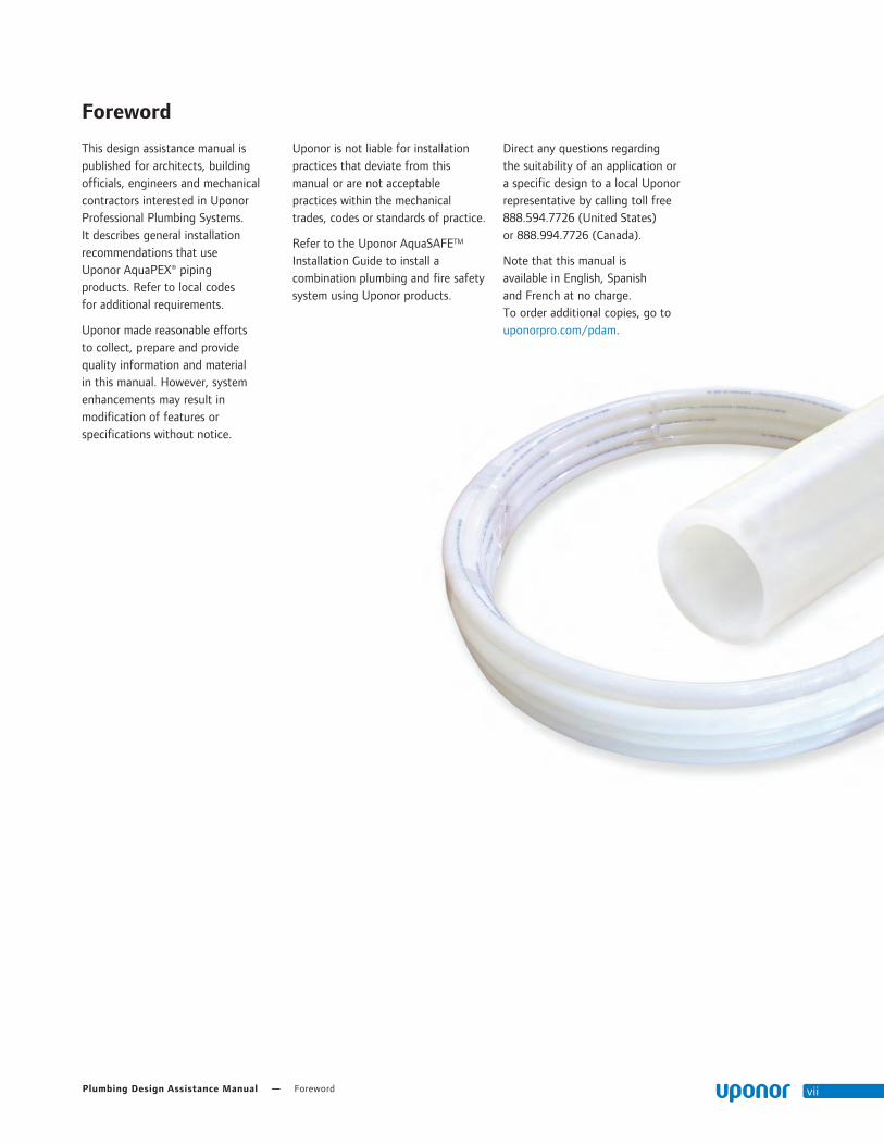
This design assistance manual is published for architects, building officials, engineers and mechanical contractors interested in Uponor Professional Plumbing Systems. It describes general installation recommendations that use Uponor AquaPEX® piping products. Refer to local codes for additional requirements.
Uponor made reasonable efforts to collect, prepare and provide quality information and material in this manual. However, system enhancements may result in modification of features or specifications without notice.
Uponor is not liable for installation practices that deviate from this manual or are not acceptable practices within the mechanical trades, codes or standards of practice.
Refer to the Uponor AquaSAFETM Installation Guide to install a combination plumbing and fire safety system using Uponor products.
Direct any questions regarding the suitability of an application or a specific design to a local Uponor representative by calling toll free 888.594.7726 (United States) or 888.994.7726 (Canada).
Note that this manual is available in English, Spanish and French at no charge. To order additional copies, go to uponorpro.com/pdam.

viii uponorengineering.com
Plumbing Design Assistance Manual — Chapter 1 – Uponor PEX Properties 1
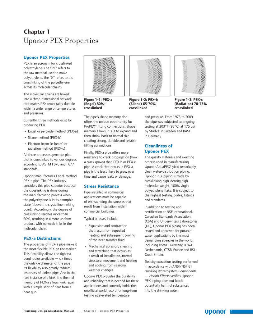
Uponor PEX PropertiesPEX is an acronym for crosslinked polyethylene. The “PE” refers to the raw material used to make polyethylene; the “X” refers to the crosslinking of the polyethylene across its molecular chains.
The molecular chains are linked into a three-dimensional network that makes PEX remarkably durable within a wide range of temperatures and pressures.
Currently, three methods exist for producing PEX.
• Engel or peroxide method (PEX-a)
• Silane method (PEX-b)
• Electron beam (e-beam) or radiation method (PEX-c)
All three processes generate pipe that is crosslinked to various degrees according to ASTM F876 and F877 standards.
Uponor manufactures Engel-method PEX-a pipe. The PEX industry considers this pipe superior because the crosslinking is done during the manufacturing process when the polyethylene is in its amorphic state (above the crystalline melting point). Accordingly, the degree of crosslinking reaches more than 80%, resulting in a more uniform product with no weak links in the molecular chain.
PEX-a Distinctions The properties of PEX-a pipe make it the most flexible PEX on the market. This flexibility allows the tightest bend radius available — six times the outside diameter of the pipe. Its flexibility also greatly reduces instances of kinked pipe. And in the rare instance of a kink, the thermal memory of PEX-a allows kink repair with a simple shot of heat from a heat gun.
The pipe’s shape memory also offers the unique opportunity for ProPEX® fitting connections. Shape memory allows PEX-a to expand and then shrink back to normal size — creating strong, durable and reliable fitting connections.
Finally, PEX-a pipe offers more resistance to crack propagation (how a crack grows) than PEX-b or PEX-c pipe. A crack that occurs in PEX-a pipe is the least likely to grow over time and cause leaks or damage.
Stress Resistance Pipe installed in commercial applications must be capable of withstanding the stresses that result from installation within commercial buildings.
Typical stresses include:
• Expansion and contraction that result from repeated heating and subsequent cooling of the heat-transfer fluid
• Mechanical abrasion, shearing and stretching that occurs as a result of installation, normal structural movement and heating and cooling from seasonal weather changes
Uponor PEX provides the durability and reliability that is needed for these applications and currently holds the unofficial world record for long-term testing at elevated temperature
and pressure. From 1973 to 2009, the pipe was subjected to ongoing testing at 203°F (95°C) at 175 psi by Studvik in Sweden and BASF in Germany.
Cleanliness of Uponor PEXThe quality materials and exacting process used in manufacturing Uponor AquaPEX® yield remarkably clean water-distribution piping. Uponor PEX piping is made by crosslinking high-density,high-molecular weight, 100% virgin polyethylene flake. It is subject to the highest testing, codes, listings and standards.
In addition to testing and certification at NSF International, Canadian Standards Association (CSA) and Underwriters Laboratories (UL), Uponor PEX piping has been tested and approved for potable-water applications by the most demanding agencies in the world, including DVWG-Germany, KIWA-Netherlands, CTSB-France and BSI-Great Britain.
Toxicity extraction testing performed in accordance with ANSI/NSF 61 Drinking Water System Components — Health Effects verifies Uponor PEX piping does not leach potentially harmful substances into the drinking water.
Chapter 1
Uponor PEX Properties
Figure 1-1: PEX-a (Engel) 80%+ crosslinked
Figure 1-2: PEX-b (Silane) 65-70% crosslinked
Figure 1-3: PEX-c (Radiation) 70-75% crosslinked
Chapter 1 – Uponor PEX Properties — uponorengineering.com2
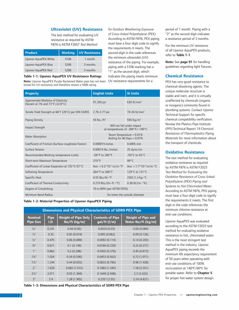
Ultraviolet (UV) ResistanceThe test method for evaluating UV resistance as required by ASTM F876 is ASTM F2657 Test Method
for Outdoor Weathering Exposure of Cross-linked Polyethylene (PEX). According to ASTM F876, PEX piping must bear a four-digit code to signify the requirements it meets. The second digit in the code references the minimum ultraviolet (UV) resistance of the piping. For example, piping with a 5106 marking has a “1” as the second digit, which indicates the piping meets minimum UV resistance requirements for a
period of 1 month. Piping with a “2” as the second digit indicates a resistance period of 3 months.
For the minimum UV resistance of all Uponor AquaPEX products, refer to Table 1-1.
Note: See page 91 for handling guidelines regarding light fixtures.
Chemical ResistancePEX has very good resistance to chemical-dissolving agents. The unique molecular structure is stable and inert, and it is virtually unaffected by chemicals (organic or inorganic) commonly found in plumbing systems. Contact Uponor Technical Support for specific chemical compatibility verification. Review the Plastics Pipe Institute (PPI) Technical Report 19 Chemical Resistance of Thermoplastics Piping Materials for more information about the transport of chemicals.
Oxidative ResistanceThe test method for evaluating oxidative resistance as required by ASTM F876 is ASTM F2023 Test Method for Evaluating the Oxidative Resistance of Cross-linked Polyethylene (PEX) Piping and Systems to Hot Chlorinated Water. According to ASTM F876, PEX piping must bear a four-digit code to signify the requirements it meets. The first digit in the code references the minimum chlorine resistance at end-use conditions.
Uponor AquaPEX was evaluated according to the ASTM F2023 test method for evaluating oxidative resistance to hot, chlorinated water. This is the most stringent test method in the industry. Uponor AquaPEX piping exceeds the minimum life expectancy requirement of 50 years when operating with end-use conditions of 100% recirculation at 140ºF/60ºC for potable water. Refer to Chapter 5
for proper hot-water system design.
Product Marking UV Resistance
Uponor AquaPEX White 5106 1 month
Uponor AquaPEX Blue 5206 3 months
Uponor AquaPEX Red 5206 3 months
Table 1-1: Uponor AquaPEX UV Resistance RatingsNote: Uponor AquaPEX Purple Reclaimed Water pipe has not been tested for UV resistance and therefore retains a 5006 rating.
Property English Units SI Units
Approximate Modulus of Elasticity (Secant at 1% and 73°F/22.8°C)
91,350 psi 630 N/mm2
Tensile Yield Strength at 68˚F (20˚C) per DIN 53455 2.76-3.77 psi 19-26 N/mm2
Piping Density 59 lbs./ft3 936 Kg/m3
Impact StrengthWill not fail under impact
at temperatures of -284°F/-140°C
Water AbsorptionRoom Temperature = 0.01% Boiling for 40 Days = 0.07%
Coefficient of Friction (Surface-roughness Factor) 0.000019 inches 0.0005 mm
Surface Tension 0.00014 lbs./inches 25 dyne/cm
Recommended Working-temperature Limits -58°F to 200°F -50°C to 93°C
Short-term Maximum Temperature 210°F 99°C
Coefficient of Linear Expansion at 135°F/57°C Ave. = 9.2*10-5 in/in-°F Ave. = 1.7*10-4 m/m-°C
Softening Temperature 264°F to 268°F 129°C to 131°C
Specific Heat 0.55 Btu/lb-°F 2302.3 J/kg-°C
Coefficient of Thermal Conductivity 0.219 Btu/(hr•ft•°F) 0.38 W/(m•°K)
Degree of Crosslinking 70 to 89% (per ASTM F876)
Minimum Bend Radius Six times the outside diameter
Table 1-2: Material Properties of Uponor AquaPEX Piping
Dimensions and Physical Characteristics of SDR9 PEX Pipe
Nominal Pipe Size
Pipe I.D.
Weight of Pipe Only lbs/ft (kg/m)
Contents of Pipe gal/ft (l/m)
Weight of Pipe and Water lbs/ft (kg/m)
¼" 0.241 0.04 (0.06) 0.0024 (0.03) 0.06 (0.089)
3⁄8" 0.35 0.05 (0.074) 0.005 (0.062) 0.09 (0.136)
½" 0.475 0.06 (0.089) 0.0092 (0.114) 0.14 (0.203)
¾" 0.671 0.1 (0.149) 0.0184 (0.229) 0.25 (0.377)
1" 0.862 0.2 (0.298) 0.0303 (0.376) 0.45 (0.673)
1¼" 1.054 0.34 (0.506) 0.0453 (0.563) 0.72 (1.071)
1½" 1.244 0.44 (0.655) 0.0632 (0.785) 0.96 (1.428)
2" 1.629 0.682 (1.015) 0.1083 (1.345) 1.58 (2.351)
2½" 2.011 0.93 (1.384) 0.1649 (2.048) 2.3 (3.423)
3" 2.4 1.28 (1.905) 0.2351 (2.92) 3.24 (4.821)
Table 1-3: Dimensions and Physical Characteristics of SDR9 PEX Pipe

Plumbing Design Assistance Manual — Chapter 1 – Uponor PEX Properties 3
Hydrostatic Temperature and Pressure RatingsThrough scientific research and historical experience, hydrostatic design basis (HDB) ratings have been shown to be useful indicators of relative long-term strength of thermoplastic materials when tested under the conditions specified in test method ASTM D2837. The HDB is used to determine the temperature and pressure ratings of a specific material. These temperature and pressure ratings are based on an extrapolated life of 50 years.
Standard PPI TR-3 defines the policies and procedures for developing HDB ratings for thermoplastic piping materials or pipe.
Uponor maintains standard-grade ratings for Uponor AquaPEX piping as tested in accordance with TR-3. Uponor AquaPEX carries the following temperature and pressure ratings shown in Table 1-4.
Note: Uponor EP and LF Brass fittings carry the same temperature and pressure ratings as Uponor AquaPEX pipe.
Interpolation Method
Pressure ratings at different temperatures are determined by using a linear relationship between the standard-grade ratings. See Table 1-5 for interpolated temperature and pressure ratings.
Excessive Temperature and Pressure Capability
In accordance with ASTM F876 Standard Specification for Crosslinked Polyethylene (PEX) Piping, the excessive temperature and pressure capability of Uponor AquaPEX is 210ºF at 150 psi (99ºC at 10 bar).
This standard requires that Uponor AquaPEX piping maintain its integrity for a period of 720 hours (30 days) at 210ºF (99ºC) at 150 psi (10 bar). If installed as directed, Uponor AquaPEX will withstand these conditions.
Note: Excessive temperature and pressure requirements are always subject to approval by local building codes (e.g., temperature and
pressure-relief valves).
ASTM F876 Temperature and Pressure Ratings for SDR9 PEX
Rated Temperature
Hydrostatic Design Stress (HDS) psi
Pressure Rating for Water psi
73.4°F/23°C 630 160
180°F/82°C 400 100
200°F/93°C 315 80
Table 1-4: Hydrostatic Temperature and Pressure Ratings for Uponor AquaPEX Piping
These listings are published in PPI TR-4, a culmination report of the listings that are maintained with PPI.
Temperature and Pressure Ratings
ºF/ºC PSI/Bar
200.0/93.3 80/5.5
190.0/87.8 90/6.2
180.0/82.2 100/6.9
170.0/76.7 106/7.3
160.0/71.1 111/7.7
150.0/65.6 117/8.0
140.0/60.0 123/8.5
130.0/54.4 128/8.8
120.0/48.9 134/9.2
110.0/43.3 139/9.6
100.0/37.8 145/10.0
90.0/32.2 151/10.4
80.0/26.7 156/10.8
73.4/23.0 160/11.0
60.0/15.6 168/11.6
50.0/10.0 173/11.9
40.0/4.4 179/12.3
Table 1-5: Interpolated Hydrostatic Temperature and Pressure Ratings for Uponor AquaPEX Piping

Chapter 1 – Uponor PEX Properties — uponorengineering.com4
Standards
ASTM International
• ASTM F876 Standard Specification for Cross-linked Polyethylene (PEX) Piping
• ASTM F877 Standard Specification for Cross-linked Polyethylene (PEX) Plastic Hot- and Cold-Water Distribution Systems
• ASTM F1960 Standard Specification for Cold Expansion Fittings with PEX Reinforcing Rings for Use with Cross-linked Polyethylene (PEX) Piping
• ASTM F2023 Standard Test Method for Evaluating the Oxidative Resistance of Cross-linked Polyethylene (PEX) Piping and Systems to Hot Chlorinated Water
• ASTM F2657 Standard Test Method for Outdoor Weathering Exposure of Cross-linked Polyethylene (PEX) Piping
• ASTM E84 Standard Test Method for Surface Burning Characteristics of Building Materials
• ASTM E119 Standard Test Methods for Fire Tests of Building Construction and Materials
• ASTM E814 Standard Test Method for Fire Tests of Through-Penetration Firestop Systems
NSF International
• ANSI/NSF Standard 14 Plastics Piping System Components and Related Materials
• ANSI/NSF Standard 61 Drinking Water System Components — Health Effects
• ANSI/NSF Standard 359 Valves for Crosslinked Polyethylene (PEX) Water Distribution Systems
American Water Works Association (AWWA)
• AWWA C904 Cross-Linked Polyethylene (PEX) Pressure Pipe, 1⁄2" (12mm) through 3" (76mm) for Water Service
Underwriters Laboratories, Inc. (UL)
• ANSI/UL 263 Standard for Safety for Fire Tests of Building Construction and Materials
• UL 1821 Standard for Safety for Thermoplastic Sprinkler Pipe and Fittings for Fire Protection Service (NFPA 13D applications only)
• UL 2846 Standard for Safety for Fire Test of Plastic Water Distribution Plumbing Pipe for Visible Flame and Smoke Characteristics
CSA Group (Canadian Standards Association)
• CAN/CSA B137.5 Crosslinked Polyethylene (PEX) Piping Systems for Pressure Applications
• CAN/CSA B214 Installation Code for Hydronic Heating Systems
American Society of Mechanical Engineers (ASME)
• ASME B16.5 Pipe Flanges and Flanged Fittings: NPS ½ through
NPS 24 Metric/Inch Standard
Underwriters Laboratories of Canada (ULC)
• CAN/ULC-S102.2 Standard Method of Test for Surface Burning Characteristics of Flooring, Floor Covering and Miscellaneous Materials and Assemblies
• CAN/ULC-S101 Standard Methods of Fire Endurance Tests of Building Construction and Materials
• CAN/ULC-S115 Standard Method of Fire Tests of Firestop Systems
• CAN/ULC/ORD-C199P Combustible Piping for Sprinkler Systems
Plastics Pipe Institute (PPI)
• PPI Technical Report TR-4
Codes
Standards, Codes and ListingsUponor AquaPEX piping is manufactured to meet the following requirements.
• ICC
• IPC
• IMC
• IRC
• UPC
• UMC
• NSPC
• HUD
• UFGS
• NPC of Canada
• NBC of Canada
Listings • cNSFus-fs
• cNSFus-rfh
• cNSFus-pw
• cQAIus
• UL
• CSA
• WH
• ETL
• PPI-TR-4
• ICC-ES-PMG
• IAPMO
• BMEC
• CCMC
Note: Obtain listings at qai.org, ul.com and nsf.org.

Plumbing Design Assistance Manual — Chapter 1 – Uponor PEX Properties 5
Elbows
Tees
Plugs
Couplings
Multiport Tees
Uponor ProPEX Engineered Polymer (EP) Fittings
Accessibility
Based on Uponor’s review of the International Plumbing Code (IPC), National Plumbing Code of Canada (NPCC) and Uniform Plumbing Code (UPC), there are no requirements for direct access to Uponor ProPEX fittings (i.e., ASTM F1960 and CAN/CSA B137.5). Thus, ProPEX fittings (which includes Uponor's Mulitport Tees) may be placed behind drywall or other coverings without the need for openings or similar means of direct access to the fittings. However, codes require that an operating valve must be accessible. Thus, a valve or similar operable component that incorporates Uponor ProPEX connections must be accessible.
Performance
EP is a high-performance thermoplastic material that has superior mechanical, chemical and thermal properties which provide dimensional stability in demanding applications, including areas of high stress, heat and moisture.
Uponor EP fittings comply with NSF/ANSI 61 health effects requirements when tested at temperatures up to and including 180ºF/82.2ºC (i.e., commercial hot water).
Durable
Resistant to corrosion, pitting and scaling, Uponor EP products are designed for any plumbing — and even heating — application, whether residential or commercial.
Note: Do not expose EP fittings to direct sunlight for more than 30 days.
Lead Free
EP fittings are the ideal solution to lead-free requirements and are even approved for direct burial in soil, making installation options endless.
Cost Effective
Uponor EP is a more cost-effective option because it offers a stable material cost and is not subject to the wide price fluctuations of metal.
ProPEX® FittingsUponor ProPEX® fittings are available in both Engineered Polymer (EP) and Lead-free (LF) brass and are tested and listed to:
• ASTM F1960 Standard Specification for Cold Expansion Fittings with PEX Reinforcing Rings for Use With Cross-linked Polyethylene (PEX) Piping
• CAN/CSA B137.5 Crosslinked Polyethylene (PEX) Piping Systems for Pressure Applications

Chapter 1 – Uponor PEX Properties — uponorengineering.com6
Figure 1-4: Beginning of Test Figure 1-5: At Approximately 2,900 lbs. of Pull Force
The Strength of Uponor EP
Uponor EP is made from UDEL® polysulfone, Radel R® polyphenylsulfone or Acudel® modified polyphenylsulfone. These materials are part of a family of polymers that have been used successfully in the demanding environments of medical appliance, aerospace and plumbing for many years. In fact, lab tests prove the Uponor 2" ProPEX EP Tee and ProPEX connection are able to withstand up to 2,900 lbs. of pull force without failure.
Uponor ProPEX Lead-free* (LF) Brass FittingsUponor offers a complete line of LF brass transition fittings, valves, stub-outs, water-heater connectors and wall boxes.
• All Uponor LF brass products comply with NSF/ANSI 61 Annex G, NSF/ANSI 372 and conform to the lead-content requirements for “lead-free” plumbing as defined by California, Vermont, Maryland and Louisiana state laws as well as the U.S. Safe Drinking Water Act, effective January 2014.
• All Uponor LF brass fittings marked as NSFus-pw-G comply with the dezincification resistance (DZR) and stress-corrosion cracking (SCC) requirements of Sections 5.8.1 and 5.8.2 per the current NSF 14 Standard.
• Uponor’s LF brass is approved for direct burial in soil per NSF/ANSI Standard 14 testing which established minimum performance criteria for DZR/SCC resistance for PEX fittings intended for potable water.
Soldering
• When soldering LF brass fittings, Uponor recommends using a lead-free flux and solder which meet the requirements of NSF/ANSI 372 or NSF/ANSI 61 Annex G. Please refer to the solder and flux manufacturer for details on properly soldering lead-free brass materials.
Fittings by OthersUponor PEX piping can be used with any type of SDR9 PEX fitting, including compression fittings. Compression fittings must be installed with an insert stiffener to ensure the pipe wall doesn’t collapse under compression, compromising the connection.
Note that Uponor cautions the use of other manufacturer’s PEX pipe with Uponor ProPEX Rings as well as using other’s expansion rings with Uponor PEX pipe. Because of the lower degree and uniformity of crosslinking in PEX-b and PEX-c pipe, stress cracking of the PEX-b and PEX-c pipe wall can occur during expansion, compromising the strength of the fitting connection. Additionally, the 25-year limited warranty for Uponor PEX systems is only valid when both Uponor PEX pipe and Uponor ProPEX fittings are used. Mixing the ProPEX Rings with other manufacturer’s PEX pipe or other’s expansion rings with Uponor PEX pipe will limit the warranty. For complete warranty details, refer to uponorpro.com/warranties.
Note: Uponor does not permit a press-type fitting to be used with standard ProPEX sweat or fitting sweat adapters. Brass material is not nearly as malleable as copper material, causing undo stress and affecting the integrity of the connection.
* Per NSF Annex G, lead-free products contain not more than 0.25% weighted average lead content on wetted surfaces.

Plumbing Design Assistance Manual — Chapter 2 – Making ProPEX Connections 7
Chapter 2::
Making ProPEX Connections
General ProPEX Connection Tips•• If•the•fitting•does•not•slide•into••the•piping•all•the•way•to•the•stop,•immediately•remove•it•from•the•piping•and•expand•the•piping•one•final•time.
Note: To•avoid•over-expanding•the•piping,•do•not•hold•the•piping•in•the•expanded•position.
•• Table 2-1•shows•the•recommended•number•of•expansions.•Experience,•technique•and•weather•conditions•influence•the•actual•number•of•expansions.•Fewer•expansions•may•be•necessary•under•certain••conditions.•The•correct•number••of•expansions•is•the•amount••necessary•for•the•piping•and••the•shoulder•of•the•fitting•to••fit•snugly•together.
•• •Ensure•the•ProPEX•Ring•rests••snugly•against•the•fitting•shoulder.•If•there•is•more•than•1⁄16"•(1mm)•between•the•ring•and•the•shoulder•of•the•fitting,•the•connection•must•be•replaced.•Square•cut•the•piping•2"•away•from•the•fitting•for•½"•to•1"•pipe,•3"•away•for•1¼"•to•2"•pipe•and•5"•away•for•2½"•and•3"•pipe•prior•to•making•the•new•connection.
•• Brass•ProPEX•fittings•can•be•disconnected•and•reused.•EP•fittings•must•be•discarded.•Be•sure•to•follow•the•recommended•minimum•distance•between•ProPEX•fittings•shown•in•Table 2-2.
Uponor•ProPEX•ASTM•F1960•and•CAN/CSA•B137.5•cold-expansion•fittings•make•solid,•permanent,•manufactured•connections•without•the•need•for•torches,•glues,•solder,•flux•or•gauges.•The•unique•shape•memory•of•Uponor•PEX•piping•forms•a•tight•seal•around•the•fitting,•
creating•a•strong,•reliable•connection.
This•document•shows•how•to•make•proper•ProPEX•connections•using•one•of•the•following•tools.
•• Milwaukee®•M12™•or•M18™•ProPEX•Expansion•Tools
•• Milwaukee•M18•FORCELOGIC™•ProPEX•Expansion•Tool
•• ProPEX•201•Corded•Expander•Tool
•• ProPEX•Hand•Expander•Tool
Distance Between FittingsUponor•requires•a•minimum•distance•between•ProPEX•fittings•to•ensure•the•fittings•are•not•damaged•during•the•expansion•process•by•the•expander•head.•Refer•to•Table 2-2•for•the•minimum•distance•between•fittings,•which•is•expressed•as•cut•length•of•pipe.•
Nominal Fitting Size
Cut Length of Pipe
½" 2"
¾" 3"
1" 3½"
1¼" 4½"
1½" 4½"
2" 6"
2½" 7½
3" 9"
Table 2-1: Recommended Number of Expansions for 3⁄8" to 3" Piping at 73.4ºF (23ºC)
Note: “H”•in•the•table•refers•to•Uponor•H-series•expander•heads.
Piping SizeMilwaukee ProPEX Tool Uponor ProPEX Tool
M12 M18 FORCELOGIC Manual 100/150 201
3/8" 8 9 — 5 7 —
½" 5 6 — 4 4 —
¾" 9 8 — 9 9H —
1" 12 5 — 14 7H —
1¼" — 7 — — 7H —
1½" — 6 — — 8H —
2" — — 4 — — 5H
2½" — — 5 — — —
3" — — 7 — — —
Table 2-2: Minimum Distance Between ProPEX Fittings
Cut Length of Pipe

Chapter 2 – Making ProPEX Connections — uponorengineering.com8
Important! Making•expansions••are•slightly•different•when•using•a•tool•that•features•auto•rotation.•When•making•a•ProPEX••connection,•be•sure•to•follow••the•guidelines•for•the•tool•you••are•using•in•your•application.
1.••Square•cut•the•PEX•piping••perpendicular•to•the•length•of••the•piping.•Remove•all•excess•material•or•burrs•that•might••affect•the•fitting•connection.
2.••Slide•the•ProPEX•Ring•over••the•end•of•the•piping•until•it•reaches•the•stop•edge.•If•using•a•ProPEX•Ring•without•a•stop•edge,•extend•the•ring•over•the•end•of•the•piping•no•more•than•1⁄16"•(1mm).
Important!•If•making•a•3⁄8"••ProPEX•Connection,•you•must••first•expand•each•side•of•the•ring•before•placing•it•on•the•piping.•Refer•to•the•“Making•3⁄8"•ProPEX•Connections”•instructions•on••page 16•for•further•information.
With Auto Rotation (Standard Milwaukee Heads)3.••Milwaukee•ProPEX•Expansion•Tools•
come•with•built-in•auto•rotation.•If•using•a•Milwaukee•expansion•head,•simply•hold•the•piping•and•tool•in•place•while•holding•the•trigger•to•expand•the•piping.•The•head•will•automatically•rotate•to•ensure•the•piping•is•evenly•expanded.•Continue•expanding•until•the•piping•and•ring•are•snug•against•the•shoulder•on•the•expander•head.•See Table 2-1•for•the•recommended•number•of•expansions•for•each•piping•size.
Note: Do•not•force•the•pipe•onto•the•expander•head.•Ensure•the•expander•head•is•rotating•during•each•expansion.
Without Auto Rotation (Standard Uponor Heads)4.••Press•the•trigger•to•expand••
the•piping.
5.••Release•the•trigger,•remove•the•head•from•the•piping,•rotate••it•1⁄8•turn•and•slide•the•head•back•into•the•piping.•Continue•expanding•and•rotating•until••the•piping•and•ring•are•snug•against•the•shoulder•on•the•expander•head.•See•Table 2-1••for•the•recommended•number••of•expansions.
Important! Rotating•the•tool•between•expansions•will•provide•smooth,•even•expansion•of•the•piping.•Failure•to•rotate•the••tool•will•cause•deep•grooves••in•the•piping•which•can•result••in•potential•leak•paths.1
2
3, 5
4
Expansion with Milwaukee M12 ProPEX Expansion Tool
3⁄8" and 1⁄2" Milwaukee Expansion Head
3⁄4" to 3" Milwaukee Expansion Heads
Making ProPEX Connections with Milwaukee ProPEX Expansion ToolsNote: All•standard•Uponor•Expander•Heads•are•compatible•with•the•M12•and•M18•tools.•Uponor•expander•heads•will•not•auto-rotate•on•the•Milwaukee•tools•(only•Milwaukee••expansion•heads•will•auto-rotate•on•the•M12•and•M18).•H-heads•are•not•compatible••with•Milwaukee•tools•and•Milwaukee•heads•are•not•compatible•with•Uponor•tools.••Milwaukee•heads•are•easily•distinguished•by•color•coding•and•the•Milwaukee•logo.
Shoulder
Shoulder

Plumbing Design Assistance Manual — Chapter 2 – Making ProPEX Connections 9
6d
6b
6e
6c6a
3, 5 4 4
6.••After•the•final•expansion,••immediately•remove•the•tool••and•insert•the•fitting.•Ensure••the•piping•and•ring•seat•against••the•shoulder•of•the•fitting.
Important! Only•perform•the•necessary•number•of•expansions.••DO•NOT•over•expand•the•pipe.••You•should•feel•some•resistance••as•the•fitting•goes•into•the•piping.••
If•you•do•not•feel•any•resistance,••the•piping•may•be•over•expanded••and•will•require•additional•time•to•shrink•over•the•fitting.•
Insert ProPEX Fitting into ½" Uponor PEX Piping.
Shoulder
Shoulder
Insert ProPEX Fitting into 1" Uponor PEX Piping.
ProPEX Coupling
ProPEX Tee
Expansion with Milwaukee M18 ProPEX Expansion Tool
Chapter 2 – Making ProPEX Connections — uponorengineering.com10
1
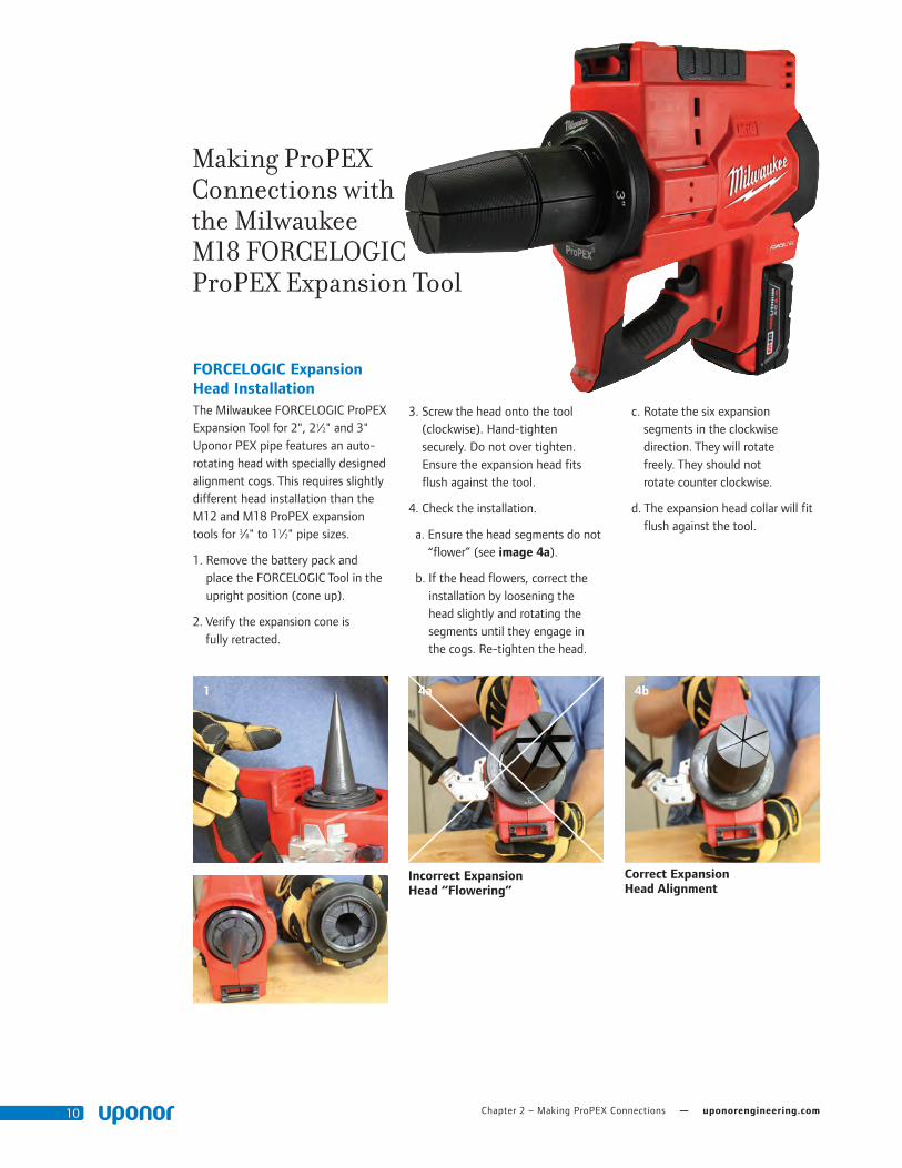
FORCELOGIC Expansion Head InstallationThe•Milwaukee•FORCELOGIC•ProPEX•Expansion•Tool•for•2",•21⁄2"•and•3"•Uponor•PEX•pipe•features•an•auto-rotating•head•with•specially•designed•alignment•cogs.•This•requires•slightly•different•head•installation•than•the•M12•and•M18•ProPEX•expansion•tools•for•3⁄8"•to•11⁄2"•pipe•sizes.
1.••Remove•the•battery•pack•and•place•the•FORCELOGIC•Tool•in•the•upright•position•(cone•up).
2.••Verify•the•expansion•cone•is•fully•retracted.
3.••Screw•the•head•onto•the•tool•(clockwise).•Hand-tighten•securely.•Do•not•over•tighten.•Ensure•the•expansion•head•fits•flush•against•the•tool.
4.••Check•the•installation.
••a.••Ensure•the•head•segments•do•not•“flower”•(see•image 4a).
••b.••If•the•head•flowers,•correct•the•installation•by•loosening•the•head•slightly•and•rotating•the•segments•until•they•engage•in•the•cogs.•Re-tighten•the•head.
••c.••Rotate•the•six•expansion•segments•in•the•clockwise•direction.•They•will•rotate•freely.•They•should•not•rotate•counter•clockwise.
••d.••The•expansion•head•collar•will•fit•flush•against•the•tool.
Making ProPEX Connections with the Milwaukee M18 FORCELOGIC ProPEX Expansion Tool
Correct Expansion Head Alignment
4b
Incorrect Expansion Head “Flowering”
4a

Plumbing Design Assistance Manual — Chapter 2 – Making ProPEX Connections 11
6
Making a ProPEX Connection 1.••Square•cut•the•PEX•piping•
perpendicular•to•the•length•of•the•piping.•Remove•all•excess•material•or•burs•that•might•affect•the•fitting•connection.
2.••Slide•the•ProPEX•Ring•over•the•end•of•the•piping•until•it•reaches•the•stop•edge.
3.••The•Milwaukee•tool•comes•with•built-in•auto•rotation,•meaning•the•head•will•automatically•rotate•to•ensure•the•piping•is•evenly•expanded.
Note:•To•cancel•the•expansion•process•quickly,•pull•and•release•the•trigger.
4.••Press•the•trigger•to•initiate•the•rotation•of•the•head.•A•green•light•will•turn•on•and•the•work•light•will•blink.•Insert•the•pipe•and•ring•and•release•the•trigger.•When•the•expansion•head•has•reached•its•maximum•diameter,•it•will•retract.
Important!•Do•not•force•the•pipe•and•ring•on•the•head•during•any•expansion.
5.••After•the•tool•has•retracted,•the•green•indicator•light•blinks•three•times.•Press•the•trigger•and•repeat•the•expansion•process.•
6.••Repeat•the•process•until•the•pipe•and•ring•are•snug•against•the•shoulder•of•the•expansion•head.•Repeat•the•expansion•one•or•two•more•times•depending•on•the•ambient•temperature.
Note:•Fewer•expansions•are•required•in•colder•temperatures.
7.••After•final•expansion,•immediately•remove•the•tool•and•insert•the•fitting.•
1
74
2a 2b
Chapter 2 – Making ProPEX Connections — uponorengineering.com12
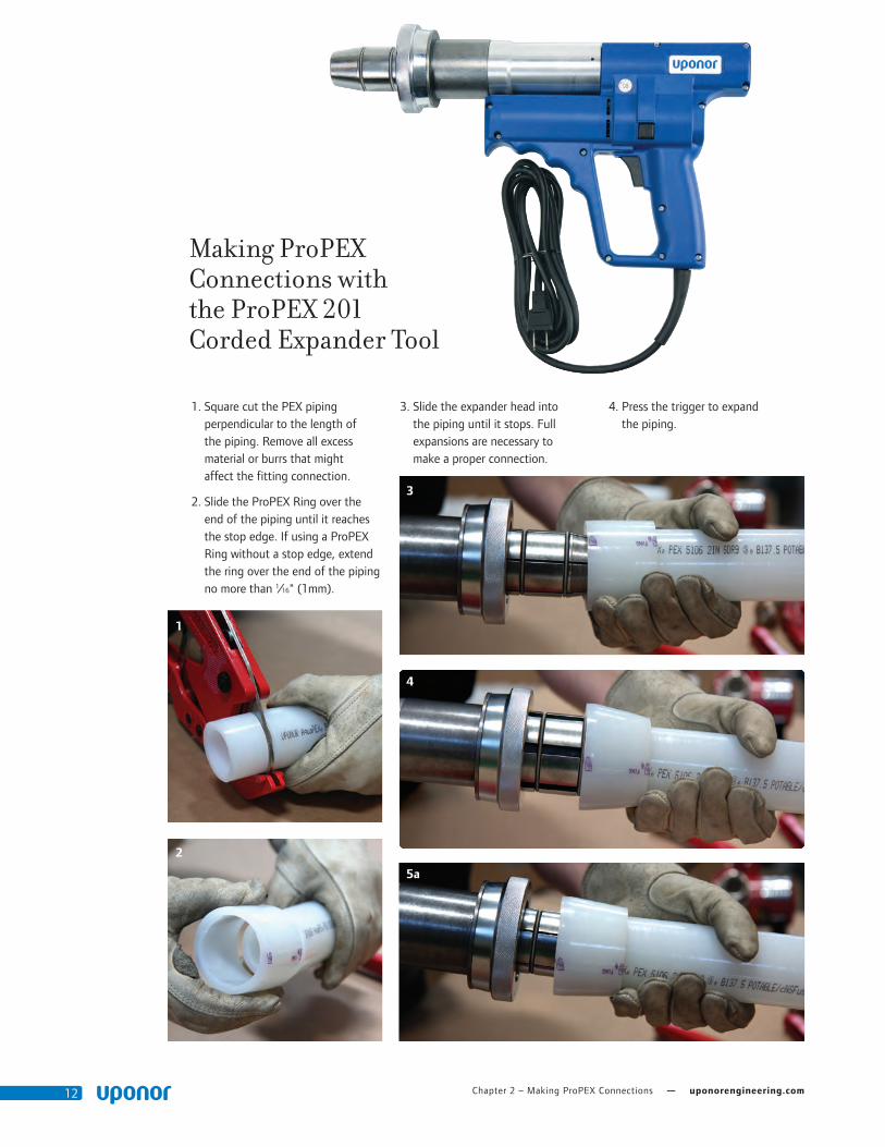
1.••Square•cut•the•PEX•piping••perpendicular•to•the•length•of••the•piping.•Remove•all•excess•material•or•burrs•that•might••affect•the•fitting•connection.
2.••Slide•the•ProPEX•Ring•over•the•end•of•the•piping•until•it•reaches•the•stop•edge.•If•using•a•ProPEX•Ring•without•a•stop•edge,•extend•the•ring•over•the•end•of•the•piping•no•more•than•1⁄16"•(1mm).
3.••Slide•the•expander•head•into••the•piping•until•it•stops.•Full•expansions•are•necessary•to••make•a•proper•connection.
4.••Press•the•trigger•to•expand••the•piping.
Making ProPEX Connections with the ProPEX 201 Corded Expander Tool
1
3
4
5a
2

Plumbing Design Assistance Manual — Chapter 2 – Making ProPEX Connections 13
5.••Release•the•trigger,•remove•the•head•from•the•piping,•rotate•it••1⁄8•turn•and•slide•the•head•back•into•the•piping.•Continue•expanding•and•rotating•until•the•piping••and•ring•are•snug•against•the•shoulder•on•the•expander•head.•See•Table 2-1•for•the•recommended•number••of•expansions.
Important! Rotating•the•tool•between•expansions•will•provide•smooth,•even•expansion•of•the•piping.•Failure•to•rotate•the•tool•will•cause•deep•grooves•in•the••piping•which•can•result•in••potential•leak•paths.
6.••After•the•final•expansion,••immediately•remove•the•tool••and•insert•the•fitting.•Ensure••the•piping•and•ring•seat•against••the•shoulder•of•the•fitting.
5b
6c
ProPEX EP Tee Inserted into Uponor PEX Piping ProPEX Brass Coupling Inserted into Uponor PEX Piping
Insert ProPEX Fitting into 2" Uponor PEX Piping.
6a
6b
Chapter 2 – Making ProPEX Connections — uponorengineering.com14
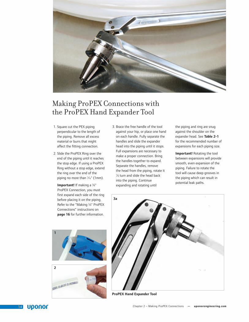
1.••Square•cut•the•PEX•piping••perpendicular•to•the•length•of••the•piping.•Remove•all•excess•material•or•burrs•that•might••affect•the•fitting•connection.
2.••Slide•the•ProPEX•Ring•over•the•end•of•the•piping•until•it•reaches•the•stop•edge.•If•using•a•ProPEX•Ring•without•a•stop•edge,•extend•the•ring•over•the•end•of•the•piping•no•more•than•1⁄16"•(1mm).
Important!•If•making•a•3⁄8"•ProPEX•Connection,•you•must•first•expand•each•side•of•the•ring•before•placing•it•on•the•piping.•Refer•to•the•“Making•3⁄8"•ProPEX•Connections”•instructions•on••page 16 for•further•information.
Making ProPEX Connections with the ProPEX Hand Expander Tool
1
2
3a
ProPEX Hand Expander Tool
3.••Brace•the•free•handle•of•the•tool•against•your•hip,•or•place•one•hand•on•each•handle.•Fully•separate•the•handles•and•slide•the•expander•head•into•the•piping•until•it•stops.•Full•expansions•are•necessary•to•make•a•proper•connection.•Bring•the•handles•together•to•expand.•Separate•the•handles,•remove••the•head•from•the•piping,•rotate•it•1⁄8•turn•and•slide•the•head•back••into•the•piping.•Continue••expanding•and•rotating•until•
the•piping•and•ring•are•snug•against•the•shoulder•on•the•expander•head.•See•Table 2-1•for•the•recommended•number•of•expansions•for•each•piping•size.
•• Important!•Rotating•the•tool•between•expansions•will•provide•smooth,•even•expansion•of•the•piping.•Failure•to•rotate•the••tool•will•cause•deep•grooves•in••the•piping•which•can•result•in•potential•leak•paths.
Plumbing Design Assistance Manual — Chapter 2 – Making ProPEX Connections 15
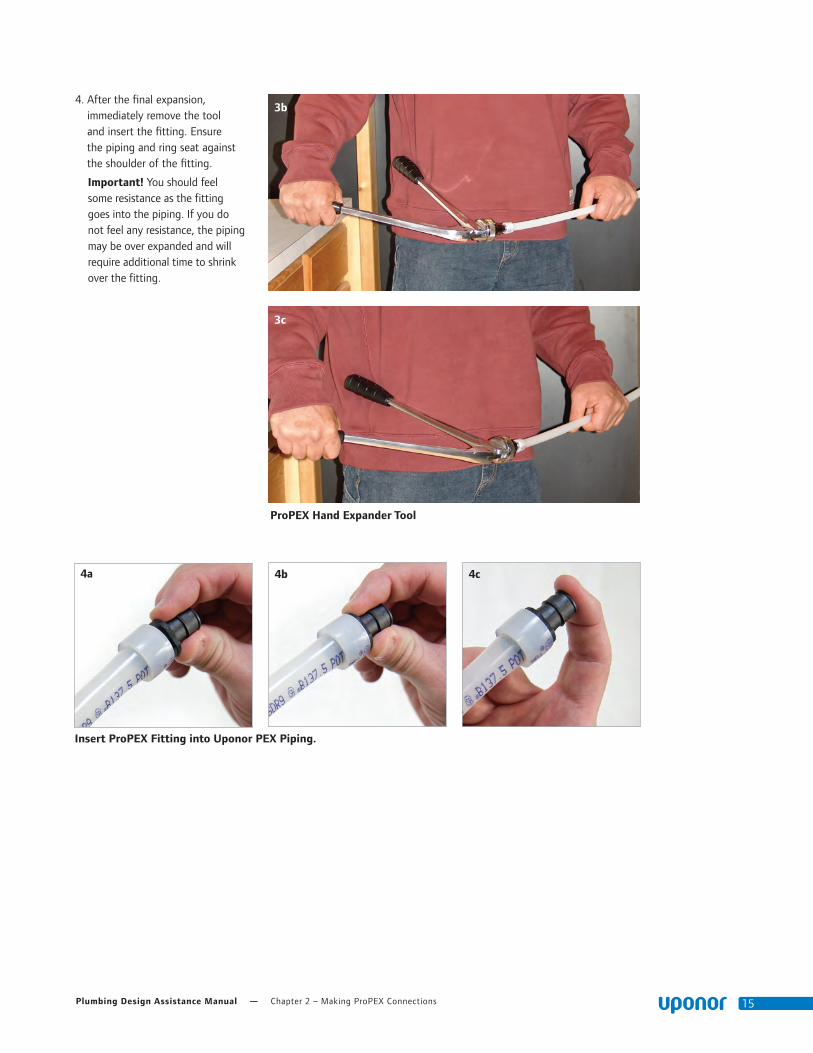
4.••After•the•final•expansion,••immediately•remove•the•tool••and•insert•the•fitting.•Ensure••the•piping•and•ring•seat•against•the•shoulder•of•the•fitting.
Important! You•should•feel••some•resistance•as•the•fitting••goes•into•the•piping.•If•you•do••not•feel•any•resistance,•the•piping•may•be•over•expanded•and•will•require•additional•time•to•shrink•over•the•fitting.
3b
3c
4b 4c4a
Insert ProPEX Fitting into Uponor PEX Piping.
ProPEX Hand Expander Tool
Chapter 2 – Making ProPEX Connections — uponorengineering.com16
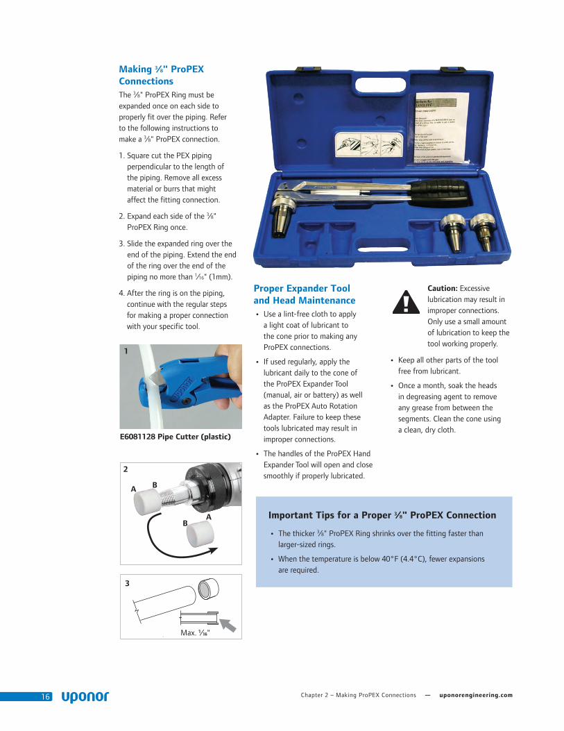
Making 3⁄8" ProPEX ConnectionsThe•3⁄8"•ProPEX•Ring•must•be••expanded•once•on•each•side•to••properly•fit•over•the•piping.•Refer••to•the•following•instructions•to••make•a•3⁄8"•ProPEX•connection.
1.••Square•cut•the•PEX•piping••perpendicular•to•the•length•of••the•piping.•Remove•all•excess•material•or•burrs•that•might••affect•the•fitting•connection.
2.••Expand•each•side•of•the•3⁄8"••ProPEX•Ring•once.
3.••Slide•the•expanded•ring•over•the•end•of•the•piping.•Extend•the•end•of•the•ring•over•the•end•of•the•piping•no•more•than•1⁄16"•(1mm).
4.••After•the•ring•is•on•the•piping,•continue•with•the•regular•steps••for•making•a•proper•connection•with•your•specific•tool.
Proper Expander Tool and Head Maintenance
•• •Use•a•lint-free•cloth•to•apply••a•light•coat•of•lubricant•to••the•cone•prior•to•making•any•ProPEX•connections.
•• •If•used•regularly,•apply•the•lubricant•daily•to•the•cone•of••the•ProPEX•Expander•Tool•(manual,•air•or•battery)•as•well•as•the•ProPEX•Auto•Rotation•Adapter.•Failure•to•keep•these•tools•lubricated•may•result•in•improper•connections.
•• •The•handles•of•the•ProPEX•Hand•Expander•Tool•will•open•and•close•smoothly•if•properly•lubricated.
Caution:•Excessive•lubrication•may•result•in•improper•connections.••Only•use•a•small•amount••of•lubrication•to•keep•the••tool•working•properly.
•• •Keep•all•other•parts•of•the•tool••free•from•lubricant.•
•• •Once•a•month,•soak•the•heads••in•degreasing•agent•to•remove••any•grease•from•between•the•segments.•Clean•the•cone•using••a•clean,•dry•cloth.
B
A
A
B
2
1
E6081128 Pipe Cutter (plastic)
3
Max.•1⁄16"
Important Tips for a Proper 3⁄8" ProPEX Connection
•• •The•thicker•3⁄8"•ProPEX•Ring•shrinks•over•the•fitting•faster•than•larger-sized•rings.
•• When•the•temperature•is•below•40°F•(4.4°C),•fewer•expansions•are•required.

Plumbing Design Assistance Manual — Chapter 2 – Making ProPEX Connections 17
4a
4c
5
64b
2
3
Disconnecting a ProPEX Brass FittingProPEX•brass•and•EP•fittings•are••manufactured•connections•that••can•be•concealed•in•walls,•ceilings••and•floors.•When•necessary,•ProPEX•brass•fittings•can•be•disconnected.
Important!•EP•fittings•cannot••be•reclaimed.
Refer•to•the•following•guidelines•for•disconnecting•a•ProPEX•brass•fitting.
1.••Ensure•the•system•is•not•pressurized.
2.••Use•a•utility•knife•to•carefully••cut•through•the•ProPEX•Ring.
Important! Do•not•heat•the•ring•prior•to•cutting•it.•Take•care•to•cut•only•the•ring•and•not•the•piping•or•fitting.•Gouges•in•the•fitting•may•result•in•leaks.•If•you•accidentally•damage•the•fitting,•you•must•discard•it.•
3.••Remove•the•ProPEX•Ring•from••the•piping.
4.••After•removing•the•ring,•apply•heat•directly•around•the•fitting•and••piping•connection.•Do not use open flame. Gently•work•the•piping•back•and•forth•while•pulling•slightly•away•from•the•fitting•until•the•piping•separates•from•the•fitting.
5.••After•removing•the•fitting,•measure:
- 2" (50.8 mm) minimum for 3⁄8" to 1" pipe
- 3" (76.2 mm) minimum for 1¼" to 2" pipe
- 5" (127 mm) minimum for 2½" and 3" pipe
6.••Square•cut•the•piping•at•the••proper•marking.
7.••Allow•the•fitting•to•cool•before•making•the•new•connection.
8.••Use•a•new•ProPEX•Ring•and••follow•the•steps•to•make•a••new•connection.

Chapter 2 – Making ProPEX Connections — uponorengineering.com18
Troubleshooting ProPEX ConnectionsTrouble-free•ProPEX•installations•begin•with•a•tool•that•is•maintained•in•proper•working•condition.•If•the•tool•or•segment•fingers•are•damaged,•it•is•very•difficult•to•make•a•proper•connection.•Refer•to•the•following•guidelines•to•assist•with•challenges••in•the•field.
Fittings Won’t Seal
•• Make•sure•the•expander•head•is•securely•tightened•onto•the•tool.
•• •Ensure•the•segment•fingers•are••not•bent.•If•the•head•does•not••completely•close•when•the•drive•unit•is•fully•retracted•or•the••handles•of•the•manual•tool•are•open,•replace•the•head.
•• •Examine•the•tool•for•excess••grease•on•the•segment•fingers.••Remove•excess•grease•prior•to••making•connections.
•• Check•the•fitting•for•damage.••Nicks•and•gouges•will•cause•the•fitting•to•leak.
•• Make•sure•the•internal•driver••cone•is•not•damaged•or•bent.
•• Make•sure•the•last•expansion•is•not•held•in•the•expanded•position•before•the•fitting•is•inserted.••You•should•feel•some•resistance••as•the•fitting•goes•into•the•piping.•If•you•do•not•feel•any•resistance,•the•piping•may•be•over•expanded•and•will•require•additional•time•to•shrink•over•the•fitting.
•• Be•sure•to•rotate•the•tool•1⁄8•turn•after•each•expansion•to•avoid•deep•grooves•in•the•piping•which•can•result•in•potential•leak•paths.
Expansion is Difficult
•• •Make•sure•the•internal•cone•is•properly•greased.
Expansion Head Slips Out of Piping When Making Expansions
•• Ensure•the•piping•and••ProPEX•Ring•are•dry.
Expansion with Proper Rotation
Expansion without Proper Rotation
•• Make•sure•that•grease•is••not•getting•into•the•piping.
•• •Examine•the•segment•fingers••to•ensure•they•are•not•damaged••or•bent.
ProPEX Ring Slides Down Piping During Expansion
•• Ensure•your•hands•are•clean•while•handling•the•piping.•Any•sweat•or•oils•on•your•hands•can•act•as•a•lubricant.•Due•to•the•smoothness•of•PEX,•any•form•of•lubricant•can•cause•the•ProPEX•Ring•to•slide•down•the•piping•during•expansion.
•• •If•you•anticipate•the•ProPEX•Ring•may•possibly•slide•down,•position•the•ring•slightly•farther•over•the•end•of•the•piping•and•make•the•first•couple•of•expansions•slowly.•Once•the•ring•and•the•piping••begin•to•expand•together,••continue•with•the•normal••number•and•type•of•expansions.
•• Place•your•thumb•against•the••ProPEX•Ring•to•help•support••it•and•feel•for•any•movement.•If•caught•early,•you•can•slide•the••ring•up•the•piping•and•expand••as•described•in•the•previous••bullet•point.
••
More Than the Recommended Number of Expansions are Needed to Make a Connection
•• Ensure•the•head•is•hand-tightened•to•the•expander•tool.
•• Examine•the•segment•fingers••for•damage.
•• Be•sure•to•completely•cycle••the•tool•on•each•expansion••(i.e.,•close•the•manual•tool••handle•or•release•the•trigger).
Cold-weather Expansions
•• Temperatures•affect•the•time••required•for•the•piping•and•ring••to•shrink•onto•the•fitting.•The•colder•the•temperature,•the•slower•the•contraction•time.
•• Warming•ProPEX•fittings•and•ProPEX•Rings•reduces•contraction•time.•Put•fittings•and•rings•in•your•pockets•prior•to•installation•to••keep•them•warm.
•• Fewer•expansions•are•necessary•in•temperatures•below•40ºF•(4.4ºC).
Note:•Do•not•use•a•heat•gun•on•EP•fittings•to•speed•up•the•contraction•time•as•this•could•result•in•damage•to•the•fitting.•

Plumbing Design Assistance Manual — Chapter 3 – Fire-resistant Construction 19
Chapter 3::
Fire-resistant Construction
Wood-frame Wall AssembliesWood-frame wall assemblies complying with ASTM E119 and CAN/ULC-S101 have the following requirements.
Building Elements
• Studs: Nominal wood 2x4 spaced 16" O.C.
• Gypsum wallboard: Minimum one layer of 5⁄8" thick Type X gypsum wallboard
Pipe and Fittings
• Pipe: Maximum density of Uponor PEX pipe is 4.85 lbs/ft (7.22 kg/m) of stud cavity. Approved Uponor PEX pipes include:
− Uponor AquaPEX White (up to 3")
− Uponor AquaPEX Red (up to 1")
− Uponor AquaPEX Blue (up to 1")
− Uponor AquaPEX Reclaimed Water (up to 1")
− Pre-insulated Uponor AquaPEX (up to 2" pipe with 1½" thick insulation)
− Wirsbo hePEX (up to 4")
• Fittings: Maximum density of Uponor ProPEX brass or EP fittings is 3.33 lbs (1.51 kg) per stud cavity.
Note: See assembly details for more information.
Assembly Numbers
ITS Design No. UW/WA 60-02
• 1-hour
• Up to 2" PEX
QAI Design No. P321-1B
• 1-hour
• Up to 4" PEX
QAI Design No. P321-1H
• 2-hour
• Up to 4" PEX
UL Design No. U372
• 1-hour
• Up to 2" PEX
Note: Maximum size is available through QAI.
Wood-frame Floor/ Ceiling AssembliesWood-frame floor/ceiling assemblies complying with ASTM E119 and CAN/ULC-S101 have the following requirements.
Building Elements
• Joists: Nominal 2x10 solid sawn wood, open web wood or wood I-joist (10" to 24" depth) installed at 24" O.C. maximum
• Subfloor: Minimum 5⁄8" plywood; if using optional topping, subfloor may be 5⁄8" oriented strand board (OSB)
• Gypsum wallboard:
− Minimum one layer of 5⁄8" Type X gypsum wallboard when using solid sawn wood joists
− Minimum two layers of ½" Type X gypsum wallboard when using wood I-joists (10" to 24" depth)
Pipe and Fittings
• Pipe: One or more Uponor PEX piping runs ½" to 2"; weight of PEX piping not to exceed 0.63 lbs/ft. (0.94 kg/m) of joist cavity. Support pipe with metal clips 16" O.C. for piping up to 1" diameter or metal clips 24" O.C. for piping larger than 1" diameter.
• Fittings: Brass or engineered polymer (EP) fittings with a weight not exceeding 0.1 lbs/ft. (0.15 kg/m) per joist cavity
Note: See assembly details for more information.
Assembly Numbers
ITS Design No. UW/FC 60-01
• 1-hour
• Up to 2" PEX
ITS Design No. UW/WA 60-02
• 1-hour
• Up to 2" PEX
QAI Design No. P321-1F
• 1-hour
• Up to 2" PEX
UL Design No. L557
• 1-hour
• Up to 2" PEX
ASTM E119 (ANSI/UL 263) or CAN/ULC-S101 Listings
Fire-resistive Assembly Ratings (ASTM E119/ANSI/UL 263 and CAN/ULC-S101)
Construction Type Assembly Type UL Design No. Intertek QAI
Non-combustable Concrete/Steel
Floor/Ceiling
K913 UW/FCA 120-01/-02 P321-1D (2-hr)
G524 - P321-1E (2-hr)
G573 - P321-1C (2-hr)
WallsV444 UW/WA 60-01 P321-1A (1-hr)
- - P321-1G (2-hr)
Wood Frame Construction
Floor/Ceiling L557 UW/FCA 60-01 P321-1F (1-hr)
WallsU372 UW/FCA 60-02 P321-1B (1-hr)
- - P321-1H (2-hr)
Table 3-1: ASTM E119 and CAN/ULC-S101 Listings

Chapter 3 – Fire-resistant Construction — uponorengineering.com20
Steel/Concrete Wall AssembliesSteel/Concrete wall assemblies complying with ASTM E119 and CAN/ULC-S101 have the following requirements.
Building Elements
Studs: 35⁄8" steel studs spaced maximum 24" O.C.
• Gypsum wallboard: Minimum one layer of 5⁄8" thick Type X gypsum wallboard
Pipe and Fittings • Pipe: Maximum density of Uponor PEX pipe is 4.85 lbs/ft (7.22 kg/m) of stud cavity. Approved Uponor PEX pipes include:
− Uponor AquaPEX White (up to 3")
− Uponor AquaPEX Red (up to 1")
− Uponor AquaPEX Blue (up to 1")
− Uponor AquaPEX Reclaimed Water (up to 1")
− Pre-insulated Uponor AquaPEX (up to 2" pipe with 1½" thick insulation)
− Wirsbo hePEX (up to 4")
• Fittings: Maximum density of Uponor ProPEX brass or EP fittings is 3.33 lbs (1.51 kg) per stud cavity.
Note: See assembly details for more information.
Assembly Numbers
QAI Design No. P321-1A
• 1-hour
• Up to 4" PEX
QAI Design No. P321-1G
• 2-hour
• Up to 4" PEX
UL Design No. V444
• 1-hour
• Up to 4" PEX
Note: Maximum size is available through QAI.
Steel/Concrete Floor/Ceiling AssembliesSteel/concrete floor/ceiling assemblies complying with ASTM E119 or CAN/ULC-S101 have the following requirements.
Building Elements
• Concrete floor: Minimum slab thickness of 6½"
• Steel Reinforcement: Various sized Grade 40 or 60 steel bars located as required by ACI-318
• Steel Joists: Minimum nominal depth of 10" spaced maximum of 6'-0" O.C.
• Steel Floor: Minimum 1½" depth, 22 gauge uncoated or galvanized fluted
Pipe and Fittings
• Pipe: Maximum volume of Uponor PEX pipe is 14 cubic inches per 1 cubic foot (8101 cubic centimeters per 1 cubic meter). Approved Uponor PEX pipes include:
− Uponor AquaPEX White (up to 2")
− Uponor AquaPEX Red (up to 1")
− Uponor AquaPEX Blue (up to 1")
− Uponor AquaPEX Reclaimed Water (up to 1")
− Pre-insulated Uponor AquaPEX (up to 1" pipe)
− Wirsbo hePEX (up to 2")
Note: See assembly details for more information.
Assembly Numbers
ITS Design No. UW/FCA 120-01
• 1-hour
• Up to 2" PEX
ITS Design No. UW/FCA 120-02
• 2-hour
• Up to 2" PEX
QAI Design No. P321-1C
• 2-hour
• Up to 2" PEX
QAI Design No. P321-1D
• 2-hour
• Up to 2" PEX
QAI Design No. P321-1E
• 2-hour
• Up to 2" PEX
UL Design No. K913
• 2-hour
• Up to 2" PEX
UL Design No. G524
• 2-hour
• Up to 2" PEX
UL Design No. G573
• 2-hour
• Up to 2" PEX

Plumbing Design Assistance Manual — Chapter 3 – Fire-resistant Construction 21
Maximum densityof Uponor ProPEXEP fittings is 3.33 lbs.(1.51 kg) per cavity
Maximum density of Uponor PEX pipeis 4.85 lbs./ft. (7.22 kg/m) per cavity
• Uponor AquaPEX (up to 3")• Pre-insulated Uponor AquaPEX
(up to 2" pipe with 2" thick insulation)
Restricted load-bearing woodjoist floor/ceiling assembly withmaximum 2" Uponor PEX pipe
Firestop listed to ASTM E814(must be Uponor PEX pipe compatible)
• Uponor AquaPEX Reclaimed Water pipe(up to 1")
Restricted-load bearing woodstud and gypsum wall assembly
Optional concrete top pour
Multiport Tee DetailWood-frame Floor/Ceiling Assembly (UL Design No. L557/QAI Design No. P321-1F)Wood-stud Wall Assembly (UL Design No. U372/QAI Design No. P321-1B)
Wood-frame Assemblies (U.S.)
Figure 3-1: Multiport Tee Detail

Chapter 3 – Fire-resistant Construction — uponorengineering.com22
2 x 4 backing plate (typical)
EP or metal drop-ear bend support, supported elbow or tee, orcopper stub ell
Restricted load-bearingwood stud and gypsumwall assembly
Wood stud
Subfloor
Optional concrete top pourPVC, EP or metal bend support
Fastener
½" or ¾" Uponor AquaPEX pipe
Fixture Detail 2Wood-frame Floor/Ceiling Assembly (UL Design No. L557/QAI Design No. P321-1F)Wood-stud Wall Assembly (UL Design No. U372/QAI Design No. P321-1B)
EP or metal drop-ear bend support, supported elbow or tee, or copper stub ell
Wood studRestricted load-bearing woodstud and gypsum wall assembly
Mid-story guide
Subfloor
Optional concrete top pourMetal support clips required up to 2" Uponor AquaPEX pipe (clip spacing every 32")
½" through 2" Uponor AquaPEX pipe
Fixture Detail 1Wood-frame Floor/Ceiling Assembly (UL Design No. L557/QAI Design No. P321-1F)Wood-stud Wall Assembly (UL Design No. U372/QAI Design No. P321-1B)
• Uponor AquaPEX (up to 3")• Pre-insulated Uponor AquaPEX
(up to 2" pipe with 2" thick insulation)
• Uponor AquaPEX Reclaimed Water pipe(up to 1")
Figure 3-2: Fixture Detail 1
Figure 3-3: Fixture Detail 2

Plumbing Design Assistance Manual — Chapter 3 – Fire-resistant Construction 23
Wood-frame Assemblies (Canada)
Restricted load-bearing woodstud and gypsum wall assembly
Maximum density ofUponor ProPEX EP fittingsis 3.33 lbs. (1.51 kg) per cavity
Maximum density of Uponor PEX pipeis 4.85 lbs./ft. (7.22 kg/m) per cavity
Firestop listed to CAN/ULC-S115(must be Uponor PEX pipe compatible)
Restricted load-bearing woodjoist floor/ceiling assembly withmaximum 2" Uponor PEX pipeOptional concrete top pour
Multiport Tee DetailWood-frame Floor/Ceiling Assembly (ITS Design No. UW/FCA 60-01/QAI Design No. P321-1F)Wood-stud Wall Assembly (ITS Design No. UW/WA 60-02/QAI Design No. P321-1B)
• Uponor AquaPEX (up to 3")• Pre-insulated Uponor AquaPEX
(up to 2" pipe with 2" thick insulation)
• Uponor AquaPEX Reclaimed Water pipe(up to 1")
Figure 3-4: Multiport Tee Detail

Chapter 3 – Fire-resistant Construction — uponorengineering.com24
Backing plate (typical)
EP or metal drop-ear bend support, supported elbow or tee, orcopper stub ell
Restricted-load bearing woodstud and gypsum wall assembly
Wood stud
Subfloor
Optional concrete top pourPVC, EP or metal bend support
Fastener
½" or ¾" Uponor AquaPEX pipe
Fixture Detail 2Wood-frame Floor/Ceiling Assembly (ITS Design No. UW/FCA 60-01/QAI Design No. P321-1F)Wood-stud Wall Assembly (ITS Design No. UW/WA 60-02/QAI Design No. P321-1B)
Non-rated wall assembly orCAN/ULC-S101 fire-rated wallinstalled with Uponor AquaPEX pipe
EP or metal drop-ear bend support, supported elbow or tee, orcopper stub ell
Mid-story guide(Uponor AquaPEX pipe only)
Optional concrete top pour
Approved firestop systemper CAN/ULC-S115 (must beUponor PEX pipe compatible)For up to 1" Uponor AquaPEX, space
clips every 16". For 1¼" to 2" UponorAquaPEX, space clips every 24".
Fixture Detail 1Wood-frame Floor/Ceiling Assembly (ITS Design No. UW/FCA 60-01/QAI Design No. P321-1F)Wood-stud Wall Assembly (ITS Design No. UW/WA 60-02/QAI Design No. P321-1B)
• Uponor AquaPEX (up to 3")
• Pre-insulated Uponor AquaPEX(up to 2" pipe with 2" thick insulation)
• Uponor AquaPEX Reclaimed Water pipe(up to 1")
Figure 3-5: Fixture Detail 1
Figure 3-6: Fixture Detail 2

Plumbing Design Assistance Manual — Chapter 3 – Fire-resistant Construction 25
Concrete Assemblies (U.S.)
Non load-bearing steel studand gypsum wall assembly
Maximum density of Uponor PEXpipe is 4.85 lbs./ft. per cavity
Restricted load-bearingfloor/ceiling assembly withmaximum 2" Uponor PEX pipe.
Firestop listed to ASTM E814 (mustbe Uponor PEX pipe compatible)
Maximum density of Uponor PEX pipeis 14 cubic inches per 1 cubic foot ofconcrete (with or without sleeving)
Maximum density ofUponor ProPEX EP fittingsis 3.33 lbs. (1.51 kg) per cavity
Multiport Tee DetailConcrete Floor/Ceiling Assembly (UL Design No. K913/QAI Design No. P321-1D)Steel-stud Wall Assembly (UL Design No. V444/QAI Design No. P321-1A)
• Uponor AquaPEX (up to 3")
• Pre-insulated Uponor AquaPEX(up to 2" pipe with 2" thick insulation)
• Uponor AquaPEX ReclaimedWater pipe (up to 1")
Non load-bearing steel studand gypsum wall assembly
Uponor EP or metal drop-ear bend support, supported elbow or tee, or copper stub ell
Firestop listed to ASTM E814requirements (must be UponorAquaPEX compatible); firestoprequired in ANSI/UL 263 wall
Steel back plate (typical)
ANSI/UL 263 slab listed withUponor AquaPEX pipe only.(ANSI/UL Design No. K913)
Approved bend support
½" or ¾" Uponor AquaPEX pipe(25 FS/50 SD)
Fixture DetailConcrete Floor/Ceiling Assembly (UL Design No. K913/QAI Design No. P321-1D)Steel-stud Wall Assembly (UL Design No. V444/QAI Design No. P321-1A)
Figure 3-8: Fixture Detail
Figure 3-7: Multiport Tee Detail

Chapter 3 – Fire-resistant Construction — uponorengineering.com26
Concrete Assemblies (Canada)
Non load-bearing steel studand gypsum wall assembly
Maximum density of Uponor PEX pipeis 4.85 lbs./ft. (4.22 kg/m) per cavity
Restricted load-bearingfloor/ceiling assembly withmaximum 2" Uponor PEX pipe
Firestop listed to CAN/ULC-S115(must be Uponor PEX pipe compatible)
Maximum density of Uponor PEX pipeis 14 cubic inches per 1 cubic foot ofconcrete (with or without sleeving)
Maximum density ofUponor ProPEX EP fittingsis 3.33 lbs. (1.51 kg) per cavity
Multiport Tee DetailConcrete Floor/Ceiling Assembly (ITS Design No. UW/FCA 120-02/QAI Design No. P321-1D)Steel-stud Wall Assembly (ITS Design No. UW/WA 60-01/QAI Design No. P321-1A)
• Uponor AquaPEX (up to 3")
• Pre-insulated Uponor AquaPEX(up to 2" pipe with 2" thick insulation)
• Uponor AquaPEX ReclaimedWater pipe (up to 1")
Non load-bearing steel studand gypsum wall assembly
Uponor EP or metal drop-ear bend support, supported elbow or tee, or copper stub ell
Approved firestop systemper CAN/ULC-S115 (must beUponor PEX pipe compatible)
Steel back plate (typical)
CAN/ULC-S101 concrete slabrated with Uponor AquaPEX pipe
Approved bend support
½" or ¾" Uponor AquaPEX pipe
Fixture DetailConcrete Floor/Ceiling Assembly (ITS Design No. UW/FCA 120-02/QAI Design No. P321-1D)Steel-stud Wall Assembly (ITS Design No. UW/WA 60-01/QAI Design No. P321-1A)
Figure 3-9: Multiport Tee Detail
Figure 3-10: Fixture Detail

Plumbing Design Assistance Manual — Chapter 3 – Fire-resistant Construction 27
The steps below show an example of how to research and find a listed fire stop assembly for PEX pipe.
Step OneChoose a fire stop solution manufacturer and consult their website or search the UL Online Certifications Directory for applicable listings. (See Figure 3-11.)
Step TwoSelect the desired and specified features of the through penetration system. Defining the country of use, assembly type, penetrating item, fire stopping product and F rating of the system may help refine search results. (See Figure 3-12.)
Step Three
Review the system matches for accuracy and consider all available options. In regards to fire listings for pressure pipe applications, domestic water piping (Division 22, Section 22 11 16) and hydronic piping (Division 23, Section 23 21 13) may be defined as being “closed” or “pressure” type systems. (See Figure 3-13 on the following page.)
ASTM E814 or CAN/ULC-S115Combustible and non-combustible pipes penetrating a wall or floor/ceiling fire-rated assembly must include a code-compliant means of passive fire protection. The function of a passive fire protection system, such as fire stopping, is to contain the fire within the area in which it started by preventing the products of combustion (smoke, hot gasses and flames) from spreading throughout the structure.
Effective fire stopping requires accurate adherence to a specific combination of
conditions that have been tested and listed as a system per ASTM E814, CAN/ULC-S115 or ANSI/UL 1479. Listed fire stop components include the penetrated substrates, penetrating item, penetration hole, insulating materials, sealants and installation method. Deviation from the listed fire assembly documentation severely compromises the effectiveness of the fire stop system.
Fire assembly documentation and listings shall be obtained from the selected fire stop solution manufacturer. Most of the fire stop manufacturers have system selector tools or navigators on their
websites to easily research and find a listing that matches the specified type
of construction.
Fire Stopping Solutions There is a wide range of fire stopping solutions that have been tested and listed with PEX pipe; including intumescent caulks, wrap strips, pass-through devices, collars and cast-in-place sleeves. Some fire stop manufacturers include, but are not limited to, 3M™, Hilti®, RectorSeal®, Passive Fire Protection Partners, Specified Technologies Inc., Holdrite® and ProSet Systems®.
Figure 3-11: UL Online Certifications Directory
Figure 3-12: Select Appropriate Features

Chapter 3 – Fire-resistant Construction — uponorengineering.com28
Product Support Line 1-800-328-1687
WL
Gypsum
2000 SeriesN
on-M
etallic P
ipes
Through Penetrations
3Fire Protection Products 3m.com/firestop
Product Support Line 1-800-328-1687W-L-2547 • 1 of 1
1. Wall Assembly – The 1 and 2 hr fire rated gypsum board/stud wall assemblies shall be constructed of the materials and in the mannerspecified in the individual U300, U400 or V400 Series Wall and Partition Designs in the UL Fire Resistance Directory and shall include thefollowing construction features:
A. Studs – Wall framing may consist of either wood studs or steel channel studs. Wood studs to consist of nom 2 by 4 in. (51 by 102 mm)lumber spaced 16 in. (406 mm) OC. Steel studs to be min 3-1/2 in. (89 mm) wide and spaced max 24 in. (610 mm) OC.
B. Gypsum Board* – Thickness, type, number of layers and fasteners as required in the individual Wall and Partition Design. Diameter of opening shall be 1-1/2 in. (38 mm) larger than the outside diam of tubing (Items 2).
The hourly F Rating of the firestop system is equal to the hourly fire rating of the wall assembly in which it is installed. The hourly T Rating is 0 and 1-3/4 hr for 1 and 2 hr rated assemblies, respectively.
2. Crosslink Polyethylene (PEX) Tubing – Nom 2 in. (51 mm) diam (or smaller) SDR 9 PEX tubing for use in closed (process or supply)piping system. Tubing installed concentrically or eccentrically within opening. Annular space between tubing and edge of opening to be min0 in. to max 1-1/2 in. (38 mm). Tubing to be rigidly supported on both sides of wall assembly.
3. Fill, Void or Cavity Materials* – Caulk or Sealant – Min 5/8 in. (16 mm) thickness of fill material applied within the annulus, flush withboth surfaces of wall assembly. An additional min 1/2 in. (13 mm) bead of fill material applied at the tubing/gypsum board interface at pointcontact location on both surfaces of wall assembly.
3M COMPANY3M FIRE PROTECTION PRODUCTS – CP 25WB+, IC 15WB+ or FB-3000 WT
*Bearing the UL Classification Mark
Reprinted from the Online Certifications Directory with permission from Underwriters Laboratories Inc. Copyright © 2010 Underwriters Laboratories Inc.®
System No. W-L-2547August 04, 2009
F Ratings – 1 and 2 Hr (See Item 1)T Ratings – 0 and 1-3/4 Hr (See Item 1)
Step FourEnsure the selected fire assembly document matches:
• Type of construction
• F rating of assembly
• Through penetrant defined as crosslinked polyethylene pipe or PEX pipe
• Range of pipe size being installed
• Penetration hole size and shape
• Fire stop solution availability
(See Figures 3-14, 3-15 and 3-16.)
Note: It may be desirable to select a fire stop product that can be used for other MEP system penetrations such as drain, waste and vent (DWV) and conduit applications. This can help ease coordination on the jobsite during the fire stop installation.
Refer to the respective firestop manufacturer for more information pertaining to the appropriate application of their products. Be mindful of information stated in the published listings to ensure
compliance during installation.
Product Support Line 1-800-328-1687
WL
Gypsum
2000 SeriesN
on-M
etallic P
ipes
Through Penetrations
3Fire Protection Products 3m.com/firestop
Product Support Line 1-800-328-1687W-L-2547 • 1 of 1
1. Wall Assembly – The 1 and 2 hr fire rated gypsum board/stud wall assemblies shall be constructed of the materials and in the mannerspecified in the individual U300, U400 or V400 Series Wall and Partition Designs in the UL Fire Resistance Directory and shall include thefollowing construction features:
A. Studs – Wall framing may consist of either wood studs or steel channel studs. Wood studs to consist of nom 2 by 4 in. (51 by 102 mm)lumber spaced 16 in. (406 mm) OC. Steel studs to be min 3-1/2 in. (89 mm) wide and spaced max 24 in. (610 mm) OC.
B. Gypsum Board* – Thickness, type, number of layers and fasteners as required in the individual Wall and Partition Design. Diameter of opening shall be 1-1/2 in. (38 mm) larger than the outside diam of tubing (Items 2).
The hourly F Rating of the firestop system is equal to the hourly fire rating of the wall assembly in which it is installed. The hourly T Rating is 0 and 1-3/4 hr for 1 and 2 hr rated assemblies, respectively.
2. Crosslink Polyethylene (PEX) Tubing – Nom 2 in. (51 mm) diam (or smaller) SDR 9 PEX tubing for use in closed (process or supply)piping system. Tubing installed concentrically or eccentrically within opening. Annular space between tubing and edge of opening to be min0 in. to max 1-1/2 in. (38 mm). Tubing to be rigidly supported on both sides of wall assembly.
3. Fill, Void or Cavity Materials* – Caulk or Sealant – Min 5/8 in. (16 mm) thickness of fill material applied within the annulus, flush withboth surfaces of wall assembly. An additional min 1/2 in. (13 mm) bead of fill material applied at the tubing/gypsum board interface at pointcontact location on both surfaces of wall assembly.
3M COMPANY3M FIRE PROTECTION PRODUCTS – CP 25WB+, IC 15WB+ or FB-3000 WT
*Bearing the UL Classification Mark
Reprinted from the Online Certifications Directory with permission from Underwriters Laboratories Inc. Copyright © 2010 Underwriters Laboratories Inc.®
System No. W-L-2547August 04, 2009
F Ratings – 1 and 2 Hr (See Item 1)T Ratings – 0 and 1-3/4 Hr (See Item 1)
Figure 3-14: Fire Assembly Document Figure 3-15: Assembly Drawing
1. Wall Assembly — The 1 and 2 hr fire rated gypsum board/stud wall assemblies shall be constructed of the materials and in the manner specified in the individuals U300, U400 or V400 Series Wall and Partition Designs in the UL Fire Resistance Directory and shall include the following construction features:
A. Studs — Wall framing may consist of either wood studs or steel channel studs. Wood studs to consist of nom 2 by 4 in. (51 by 102 mm) lumber spaced 16 in. (406 mm) OC. Steel studs to be min 3-1/2 in. (89 mm) wide and spaced max 24 in. (610 mm) OC.
B. Gypsum Board* —Thickness, type, number of layers and fasteners as required in the individuals Wall and Partition Design. Diameter of opening shall be 1-1/2 in. (38 mm) larger than the outside diameter of tubing (Items 2).
The hourly F Rating of the firestop system is equal to the hourly fire rating of the wall assembly in which it is install. The hourly T Rating is 0 and 1-3/4 hr for 1 and 2 hr rated assemblies, respectively.
2. Crosslink Polyethylene (PEX) Tubing — Nom 2 in. (51 mm) diameter (or smaller) SDR 9 PEX tubing for use in closed (process or supply) piping system. Tubing installed concentrically or eccentrically within opening. Annular space between tubing and edge of opening to be min 0 in. to max 1-1/2 in. (38 mm). Tubing to be rigidly supported on both sides of wall assembly.
3. Fill, Void or Cavity Materials* — Caulk or Sealant — Min 5/8 in. (16 mm) thickness of fill materials applied within the annulus, flush with both surfaces of wall assembly. An additional min 1/2 in. (13 mm) bead of fill material applied at the tubing/gypsum board interface at point contact location on both surfaces of wall assembly.
3M COMPANY3M FIRE PROTECTION PRODUCTS — CP25WB+, IC15WB+ OR FB-3000WT
*Bearing the UL Classification Mark
Reprinted from the Online Certifications Directory with permission from Underwriters Laboratories Inc.
Copyright © 2010 Underwriters Laboratories Inc. ®
Figure 3-16: Assembly Criteria
Figure 3-13: Search Results
WL2547 3M™ Fire Barrier Sealant CP 25WB+1, 2 3M™ Fire Barrier Sealant IC 15WB+ 3M™ Fire Barrier Water tight Sealant 3000 WT
Max 2" SDR 9 PEX (closed only). U300, U400, or V400 series gypsum wallboard assemblies. Max. diameter of opening 11⁄2" larger than OD of penetrant. Point contact to max. 11⁄2" annular space. Concentric or eccentric installations. 1 & 2 hour F rating. No mineral wool required.
UL

Plumbing Design Assistance Manual — Chapter 3 – Fire-resistant Construction 29
Figure 3-17: Cast-in-place Sleeves
Cast-in-place SleevesSeveral manufacturers offer cast-in-place sleeves, which provide floor/ceiling penetrations in concrete slab applications. Some manufactures include:
• Holdrite HydroFlame • ProSet Systems • Hilti
Refer to the respective manufacturer’s website for detailed product information.
Assembly Types
Manufacturer
3M™ Hilti® RectorSeal® STI
Wall Floor/Clg Wall Floor/Clg Wall Floor/Clg Wall Floor/Clg
Woo
d-st
ud/s
teel
-stu
d A
ssem
blie
s
1-hour
PHV-120-04 F-C-2039 W-L-2186 F-C-2081 W-L-2342 F-C-2298 F-C-2319 F-C-2032
PHV-120-11 F-C-2240 W-L-2235 F-C-2230 W-L-2262 F-C-8015 W-L-2100 F-C-2252
W-L-2091 F-C-2343 W-L-2466 F-C-2310 W-L-2373 F-C-2329 W-L-2144 F-C-2319
W-L-2146 F-C-2344 W-L-2474 F-C-2334 W-L-2430 F-C-2212 W-L-2241 F-E-2003
W-L-2173 F-C-2391 F-C-8038 W-L-2526 W-L-2242
W-L-2448 F-E-2002 F-C-8044 W-L-2121 W-L-2423
W-L-2483 F-E-2012 W-L-2209 W-L-2508
W-L-2543 F-E-2040 W-L-2528 W-L-2548
W-L-2547 PHV-120-04 W-L-2402 W-L-2549
W-L-7193
2-hour
PHV-120-04 PHV-120-04 W-L-2186 F-C-2081 W-L-2342 W-L-2100
C-AJ-2510 W-L-2235 F-C-2310 W-L-2262 W-L-2144
PHV-120-11 W-L-2466 W-L-2373 W-L-2241
W-L-2090 W-L-2474 W-L-2430 W-L-2242
W-L-2091 W-L-2526 W-L-2423
W-L-2146 W-L-2121 W-L-2508
W-L-2448 W-L-2209 W-L-2548
W-L-2483 W-L-2528 W-L-2549
W-L-2543 W-L-2402 W-L-7193
W-L-2547
Con
cret
e A
ssem
blie
s
2-hour
C-AJ-2510 C-AJ-2510 C-AJ-2170 C-AJ-2170 W-J-2162 C-AJ-2628 W-J-2021 C-AJ-2031
C-AJ-2536 C-AJ-2536 C-AJ-2407 C-AJ-2407 W-J-2122 F-A-2171 W-J-2043 C-AJ-2140
PH-120-10 F-A-2115 C-AJ-2647 C-AJ-2647 W-J-2180 F-A-8033 W-J-2076 C-AJ-2291
PHV-120-04 PH-120-10 F-B-2040 W-J-2025 C-AJ-2701 W-J-2077 F-A-2186
PHV-120-11 PHV-120-04 F-B-2041 C-AJ-2628 W-J-2232 F-A-2225
C-AJ-2213 PHV-120-11 F-A-2142 C-AJ-2679 W-J-2233
C-AJ-2378 C-AJ-2076 W-J-2071 C-AJ-2701 W-J-5148
W-J-2231
W-J-2110
3-hour
C-BJ-2028 C-BJ-2028 C-AJ-2176 C-AJ-2176 C-AJ-2578
C-BJ-2040 C-BJ-2040 F-A-2203
C-BJ-2041 C-BJ-2041 F-A-2204
Table 3-2: Fire Assemblies per Manufacturer
Note: This table is not meant to address every compatible fire assembly or firestop manufacturer. It is the end user’s responsibility to ensure that the fire assembly documentation being used is approved and current for the specific application. Please refer to the respective manufacturer’s website for detailed listing information.
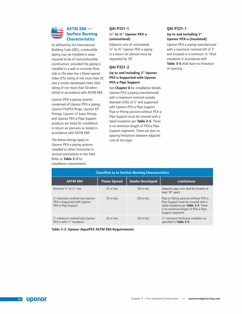
Chapter 3 – Fire-resistant Construction — uponorengineering.com30
ASTM E84 — Surface Burning Characteristics
As defined by the International Building Code (IBC), combustible piping may be installed in areas required to be of noncombustible construction, provided the piping is installed in a wall or concrete-floor slab or the pipe has a flame-spread index (FS) rating of not more than 25 and a smoke-developed index (SD) rating of not more than 50 when tested in accordance with ASTM E84.
Uponor PEX-a piping systems comprised of Uponor PEX-a piping, Uponor ProPEX Rings, Uponor EP fittings, Uponor LF brass fittings and Uponor PEX-a Pipe Support products are listed for installation in return-air plenums as tested in accordance with ASTM E84.
The below listings apply to Uponor PEX-a piping systems installed in either horizontal or vertical orientations in the field. Refer to Table 3-3 for installation requirements.
QAI P321-1½" to ¾" Uponor PEX-a (uninsulated)
Adjacent runs of uninsulated ½" to ¾" Uponor PEX-a piping in a return-air plenum must be separated by 18".
QAI P321-2Up to and Including 3" Uponor PEX-a Supported with Uponor PEX-a Pipe Support
See Chapter 6 for installation details. Uponor PEX-a piping manufactured with a maximum nominal outside diameter (OD) of 3" and supported with Uponor PEX-a Pipe Support. Pipe or fitting sections without PEX-a Pipe Support must be covered with a rated insulation per Table 3-5. There is no minimum length of PEX-a Pipe Support segments. There are also no spacing limitations between adjacent runs of this pipe.
QAI P321-1Up to and Including 3" Uponor PEX-a (insulated)
Uponor PEX-a piping manufactured with a maximum nominal OD of 3" and encased in a minimum ½" thick insulation in accordance with Table 3-5 shall have no limitation on spacing.
Classified as to Surface Burning Characteristics
ASTM E84 Flame Spread Smoke Developed Limitations
Nominal 1⁄2" to 3⁄4" size 25 or less 50 or less Adjacent pipe runs shall be located at least 18" apart.
3" maximum nominal size Uponor PEX-a Supported with Uponor PEX-a Pipe Support
25 or less 50 or less Pipe or fitting sections without PEX-a Pipe Support must be covered with a rated insulation per Table 3-5. There is no minimum length of PEX-a Pipe Support segments.
3" maximum nominal size Uponor PEX-a with 1⁄2" insulation
25 or less 50 or less 1⁄2" minimum thickness insulation as specified in Table 3-5.
Table 3-3: Uponor AquaPEX ASTM E84 Requirements

Plumbing Design Assistance Manual — Chapter 3 – Fire-resistant Construction 31
United States — ASTM E84
Minimum 18"Clamp
½" through ¾" Uponor PEX pipe
No limitation Clamp
Minimum ½" 25/50rated insulation
½" through 3" Uponor PEX pipe
No limitationClamp
½" through 3" Uponor PEX pipe
Uponor PEX-a Pipe Support
Guidelines: ½" through ¾" (uninsulated) Limitations: Adjacent runs shall be located at least 18" apart.
Guidelines: ½" through 3" (insulated) Limitations: ½" minimum thickness insulation as specified in Table 3-3
Guidelines: ½" through 3" (PEX-a Pipe Support) Pipe or fitting sections without PEX-a Pipe Support must be covered with a rated insulation per Table 3-5. There is no minimum length of PEX-a Pipe Support segments.
Figure 3-18: QAI P321-1
Figure 3-19: QAI P321-1
Figure 3-20: QAI P321-2

Chapter 3 – Fire-resistant Construction — uponorengineering.com32
CAN/ULC-S102.2 — Surface Burning Characteristics
As defined by the National Building Code of Canada (NBCC), combustible piping may be installed in areas required to be of noncombustible construction, provided the piping is installed in a wall or concrete-floor slab or the pipe has a flame-spread index (FS) rating of not more than 25 and a smoke-developed index (SD) rating of not more than 50 when tested in accordance with CAN/ULC-S102.2.
Uponor PEX-a piping systems comprised of Uponor PEX-a piping, Uponor ProPEX Rings, Uponor EP fittings, Uponor LF brass fittings and Uponor PEX-a Pipe Support
products are listed for installation in return-air plenums as tested in accordance with CAN/ULC-S102.2.
The below listings apply to Uponor PEX-a Piping Systems installed in either horizontal or vertical orientations in the field. Refer to Table 3-4 for installation requirements.
QAI P321-1½" Uponor PEX-a (Uninsulated)
Adjacent runs of un-insulated ½" Uponor PEX-a piping in a return-air plenum have no spacing limitations.
¾" and 1" Uponor PEX-a (Uninsulated)
Adjacent runs of uninsulated 3⁄4" and 1" Uponor PEX-a piping must be separated by 18".
QAI P321-1Up to and including 3" Uponor PEX (insulated)
Uponor PEX piping manufactured with a maximum nominal OD of 3" and encased in ½" insulation in accordance with Table 3-4 shall have no limitation on spacing.
QAI P321-3Up to and Including 2" Uponor PEX-a (Water-filled, Uninsulated)
Adjacent runs of water-filled, uninsulated piping in a return-air plenum have a no spacing limitations.
Classified as to Surface Burning Characteristics
CAN/ULC S102.2 Flame Spread Smoke Developed Limitations
1⁄2" nominal size 25 or less 50 or less No spacing limitations.
3⁄4" and 1" nominal sizes 25 or less 50 or less Adjacent pipe runs shall be located at least 18" apart.
2" maximum nominal size (water-filled) 25 or less 50 or less No spacing limitations.
3" maximum nominal size Uponor PEX-a with 1⁄2" insulation
25 or less 50 or less 1⁄2" minimum thickness insulation as specified in Table 3-5.
Table 3-4: Uponor AquaPEX CAN/ULC-S102.2 Requirements

Plumbing Design Assistance Manual — Chapter 3 – Fire-resistant Construction 33
Canada — CAN/ULC-S102.2
½" Uponor PEX pipe(uninsulated)
ClampNo limitation
¾" and 1"Uponor PEX pipe(uninsulated)
ClampMinimum 18"
½" through 2"Uponor PEX pipe(water-filled, uninsulated)
ClampNo limitation
Guidelines: ½" (uninsulated) Limitations: No spacing limitations.
Guidelines: 3⁄4" and 1" (uninsulated) Limitations: Adjacent pipe runs shall be located at least 18" apart.
Guidelines: ½" through 2" (water-filled) Limitations: No spacing limitations
Figure 3-21: QAI P321-1
Figure 3-22: QAI P321-1
Figure 3-23: QAI P321-3
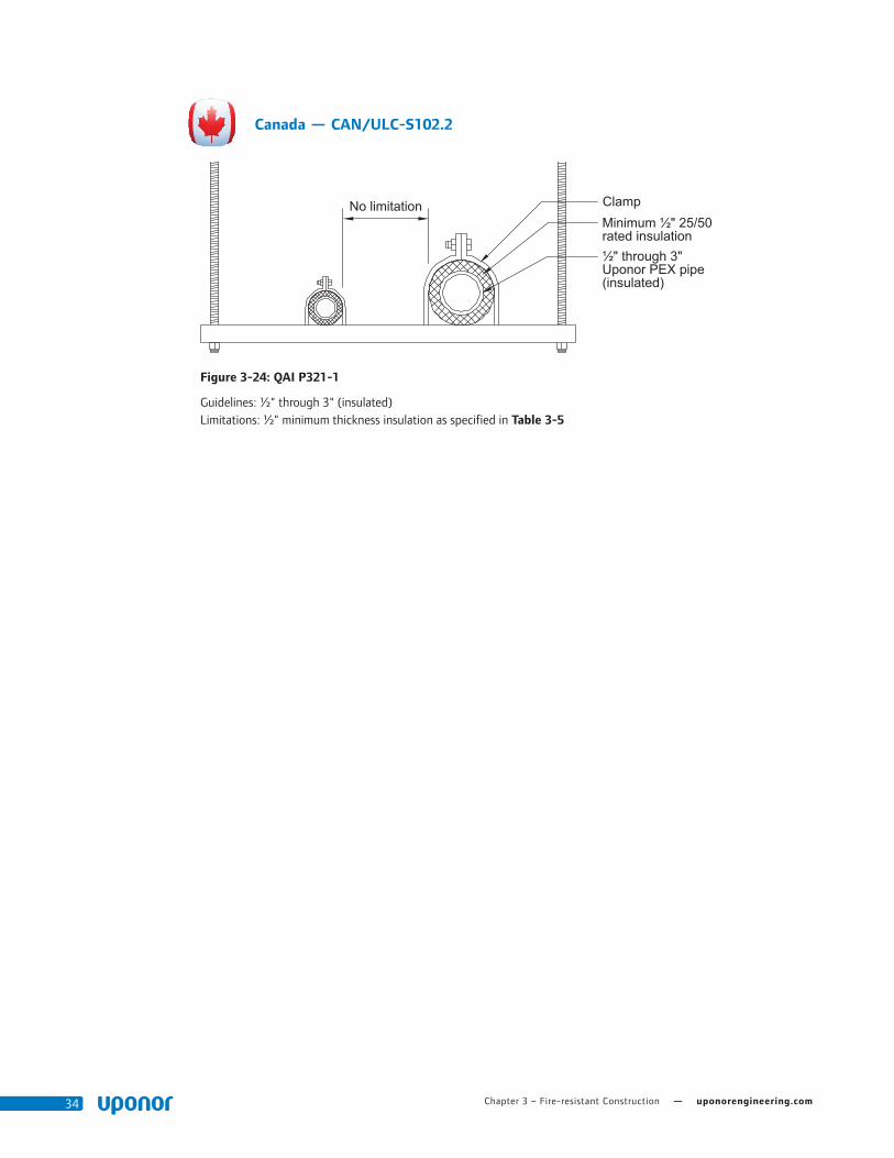
Chapter 3 – Fire-resistant Construction — uponorengineering.com34
No limitation Clamp
½" through 3" Uponor PEX pipe(insulated)
Minimum ½" 25/50rated insulation
Canada — CAN/ULC-S102.2
Guidelines: ½" through 3" (insulated) Limitations: ½" minimum thickness insulation as specified in Table 3-5
Figure 3-24: QAI P321-1
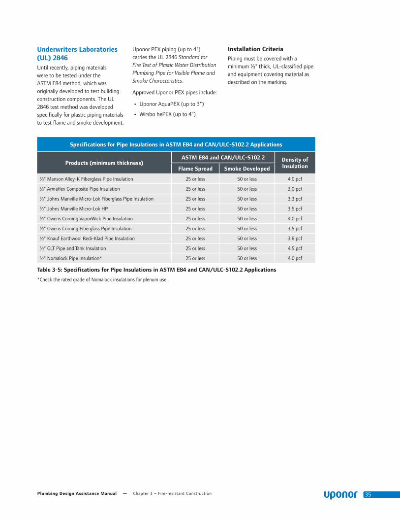
Plumbing Design Assistance Manual — Chapter 3 – Fire-resistant Construction 35
Underwriters Laboratories (UL) 2846 Until recently, piping materials were to be tested under the ASTM E84 method, which was originally developed to test building construction components. The UL 2846 test method was developed specifically for plastic piping materials to test flame and smoke development.
Uponor PEX piping (up to 4") carries the UL 2846 Standard for Fire Test of Plastic Water Distribution Plumbing Pipe for Visible Flame and Smoke Characteristics.
Approved Uponor PEX pipes include:
• Uponor AquaPEX (up to 3")
• Wirsbo hePEX (up to 4")
Installation CriteriaPiping must be covered with a minimum ½" thick, UL-classified pipe and equipment covering material as described on the marking.
Specifications for Pipe Insulations in ASTM E84 and CAN/ULC-S102.2 Applications
Products (minimum thickness)ASTM E84 and CAN/ULC-S102.2 Density of
InsulationFlame Spread Smoke Developed
1⁄2" Manson Alley-K Fiberglass Pipe Insulation 25 or less 50 or less 4.0 pcf
1⁄2" Armaflex Composite Pipe Insulation 25 or less 50 or less 3.0 pcf
1⁄2" Johns Manville Micro-Lok Fiberglass Pipe Insulation 25 or less 50 or less 3.3 pcf
1⁄2" Johns Manville Micro-Lok HP 25 or less 50 or less 3.5 pcf
1⁄2" Owens Corning VaporWick Pipe Insulation 25 or less 50 or less 4.0 pcf
1⁄2" Owens Corning Fiberglass Pipe Insulation 25 or less 50 or less 3.5 pcf
1⁄2" Knauf Earthwool Redi-Klad Pipe Insulation 25 or less 50 or less 3.8 pcf
1⁄2" GLT Pipe and Tank Insulation 25 or less 50 or less 4.5 pcf
1⁄2" Nomalock Pipe Insulation* 25 or less 50 or less 4.0 pcf
Table 3-5: Specifications for Pipe Insulations in ASTM E84 and CAN/ULC-S102.2 Applications
*Check the rated grade of Nomalock insulations for plenum use.

Chapter 3 – Fire-resistant Construction — uponorengineering.com36
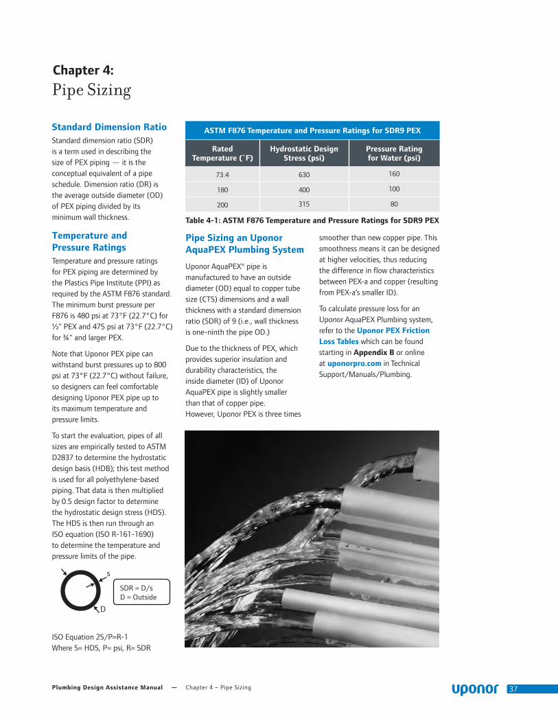
Plumbing Design Assistance Manual — Chapter 4 – Pipe Sizing 37
Chapter 4::
Pipe Sizing
Standard Dimension RatioStandard dimension ratio (SDR) is a term used in describing the size of PEX piping — it is the conceptual equivalent of a pipe schedule. Dimension ratio (DR) is the average outside diameter (OD) of PEX piping divided by its minimum wall thickness.
Temperature and Pressure RatingsTemperature and pressure ratings for PEX piping are determined by the Plastics Pipe Institute (PPI) as required by the ASTM F876 standard. The minimum burst pressure per F876 is 480 psi at 73°F (22.7°C) for ½" PEX and 475 psi at 73°F (22.7°C) for ¾" and larger PEX.
Note that Uponor PEX pipe can withstand burst pressures up to 800 psi at 73°F (22.7°C) without failure, so designers can feel comfortable designing Uponor PEX pipe up to its maximum temperature and pressure limits.
To start the evaluation, pipes of all sizes are empirically tested to ASTM D2837 to determine the hydrostatic design basis (HDB); this test method is used for all polyethylene-based piping. That data is then multiplied by 0.5 design factor to determine the hydrostatic design stress (HDS). The HDS is then run through an ISO equation (ISO R-161-1690) to determine the temperature and pressure limits of the pipe.
ISO Equation 2S/P=R-1 Where S= HDS, P= psi, R= SDR
Pipe Sizing an Uponor AquaPEX Plumbing System
Uponor AquaPEX® pipe is manufactured to have an outside diameter (OD) equal to copper tube size (CTS) dimensions and a wall thickness with a standard dimension ratio (SDR) of 9 (i.e., wall thickness is one-ninth the pipe OD.)
Due to the thickness of PEX, which provides superior insulation and durability characteristics, the inside diameter (ID) of Uponor AquaPEX pipe is slightly smaller than that of copper pipe. However, Uponor PEX is three times
smoother than new copper pipe. This smoothness means it can be designed at higher velocities, thus reducing the difference in flow characteristics between PEX-a and copper (resulting from PEX-a’s smaller ID).
To calculate pressure loss for an Uponor AquaPEX Plumbing system, refer to the Uponor PEX Friction Loss Tables which can be found starting in Appendix B or online at uponorpro.com in Technical Support/Manuals/Plumbing.
s
D
SDR = D/s D = Outside
ASTM F876 Temperature and Pressure Ratings for SDR9 PEX
Rated Temperature (˚F)
Hydrostatic Design Stress (psi)
Pressure Rating for Water (psi)
73.4 630 160
180 400 100
200 315 80
Table 4-1: ASTM F876 Temperature and Pressure Ratings for SDR9 PEX

Chapter 4 – Pipe Sizing — uponorengineering.com38
flow170% GREATER
29% LARGER I.D.
1 When comparing 1" F1960 engineered polymer (EP) with F2159 plastic fittings.
C
NOTES:
1. RADIUS ALL CORNERS .005 - .015, UNLESS OTHERWISE SPECIFIED
2. REGRIND NOT ALLOWED AC
A
B
C
D
WIRSBO COMPANYCAD GENERATED DRAWING,DO NOT MANUALLY UPDATE
SCALE
SIZE
CAD FILE:
PART NO.
A
SHEET OF
REV.
APPROVALS DATE
DRAWN BY
APPROVED BY
UNLESS OTHERWISE SPECIFIEDDIMENSIONS ARE IN INCHESTOLERANCES ARE:
MATERIALACUDEL 22000BK937
DO NOT SCALE DRAWING
2345678
A
B
C
D
2345678
5925 148TH STREET WESTAPPLE VALLEY, MN 55124
PHONE (952) 891 - 2000 FAX (952) 891 - 1246
P4755050 ACP4755050
ALP 07/21/05
REVISIONS
LETTER ECO # DATE
THE INFORMATION CONTAINED IN THISDRAWING IS THE SOLE PROPERTY OF UPONOR WIRSBO. ANY REPRODUCTIONIN PART OR WHOLE WITHOUT THE WRITTEN PERMISSION OF UPONORWIRSBO IS PROHIBITED.
ANGLES ± 1 ∞
.X ± .06
.XX ± .01
.XXX ± .005
SURFACE FINISH UNLESSOTHERWISE SPECIFIED:
125
250
250
MACH./ MOLDED
OTHERDRILLED
SSC EP TEE,1/2" PEX x 1/2" PEX x 1/2" PEX
-
AA NO PRINT
AB APV20650 08/10/05
AC APV20718 09/06/06
LDH 09/11/06
2x R.050
3x P1110502-AA
SECTION A-A
3x .04
2.3 REF
ÿ .485 ±.010
BACK SIDE MARKINGSDETAIL
"Supplier ID" "Countryof Origin"
"Date Code"
C
A - Flow path
B - Internal
diameter
ASTM F1807/F2159
Insert Fitting
ProPEX ASTM F1960 and CAN/CSA B137.5
Expansion Fitting
Uponor ProPEX Cold-expansion Fitting Standard Insert (Crimp) Fitting
ASTM F1960 Brass ASTM F1960 EP ASTM F1807 Brass ASTM F2159 Plastic
A Flow Path
1⁄2"0.112 sq. inches 2.8 gpm @ 8 ft./sec. 4.2 gpm @ 12 ft./sec.
0.116 sq. inches 2.9 gpm @ 8 ft./sec. 4.4 gpm @ 12 ft./sec.
0.096 sq. inches 2.4 gpm @ 8 ft./sec. 3.6 gpm @ 12 ft./sec.
0.078 sq. inches 1.9 gpm @ 8 ft./sec. 2.9 gpm @ 12 ft./sec.
3⁄4"0.278 sq. inches 6.9 gpm @ 8 ft./sec. 10.4 gpm @ 12 ft./sec.
0.273 sq. inches 6.8 gpm @ 8 ft./sec. 10.2 gpm @ 12 ft./sec.
0.221 sq. inches 5.5 gpm @ 8 ft./sec. 8.3 gpm @ 12 ft.sec.
0.166 sq. inches 4.1 gpm @ 8 ft./sec. 6.2 gpm @ 12 ft./sec.
1"0.496 sq. inches 12.4 gpm @ 8 ft./sec. 18.6 gpm @ 12 ft./sec.
0.488 sq. inches 12.2 gpm @ 8 ft./sec. 18.2 gpm @ 12 ft./sec.
0.396 sq. inches 9.9 gpm @ 8 ft./sec. 14.8 gpm @ 12 ft./sec.
0.292 sq. inches 7.3 gpm @ 8 ft./sec. 10.9 gpm @ 12 ft./sec.
11⁄4"0.724 sq. inches 21.8 gpm @ 8 ft./sec. 32.6 gpm @ 12 ft./sec.
0.739 sq. inches 18.4 gpm @ 8 ft./sec. 27.6 gpm @ 12 ft./sec.
0.595 sq. inches 14.8 gpm @ 8 ft./sec. 22.2 gpm @ 12 ft./sec.
Not Available
11⁄2"0.923 sq. inches 23.0 gpm @ 8 ft./sec. 34.5 gpm @ 12 ft./sec.
0.923 sq. inches 23.0 gpm @ 8 ft./sec. 34.5 gpm @ 12 ft./sec.
0.817 sq. inches 20.4 gpm @ 8 ft./sec. 30.6 gpm @ 12 ft./sec.
Not Available
2"1.877 sq. inches 47.1 gpm @ 8 ft./sec. 70.6 gpm @ 12 ft./sec.
1.730 sq. inches 43.1 gpm @ 8 ft./sec. 64.7 gpm @ 12 ft./sec.
1.463 sq. inches 36.5 gpm @ 8 ft./sec. 54.7 gpm @ 12 ft./sec.
Not Available
21⁄2"3.110 sq. inches 77.6 gpm @ 8 ft./sec. 116.3 gpm @ 12 ft./sec.
2.688 sq. inches 67.0 gpm @ 8 ft./sec. 100.6 gpm @ 12 ft./sec.
Not Available Not Available
3"4.562 sq. inches 113.8 gpm @ 8 ft./sec. 170.6 gpm @ 12 ft./sec.
3.871 sq. inches 96.5 gpm @ 8 ft./sec. 144.8 gpm @ 12 ft./sec.
Not Available Not Available
B Minimum Internal Diameter
1⁄2" 0.378" 0.385" 0.350" 0.315"
3⁄4" 0.595" 0.590" 0.530" 0.460"
1" 0.795" 0.788" 0.710" 0.610"
11⁄4" 0.960" 0.970" 0.870" Not Available
11⁄2" 1.084" 1.084" 1.020" Not Available
2" 1.550" 1.484" 1.365" Not Available
21⁄2" 1.990" 1.850" Not Available Not Available
3" 2.410" 2.220" Not Available Not Available
Table 4-2: Uponor ProPEX Fittings vs. Standard Insert (Crimp) Fittings
Note: Refer to Table C-1 in Appendix C for an equivalent length comparison.
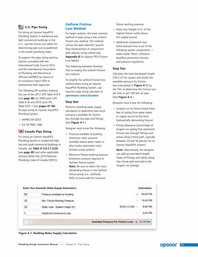
Plumbing Design Assistance Manual — Chapter 4 – Pipe Sizing 39
U.S. Pipe Sizing
For sizing an Uponor AquaPEX Plumbing System in residential and light commercial buildings in the U.S., use the fixture unit tables for determining pipe size as published in the model plumbing codes.
To support this pipe sizing practice, Uponor consulted with the International Code Council (ICC) and the International Association of Plumbing and Mechanical Officials (IAPMO) by means of an evaluation report (ER) to substantiate their approvals.
The following ER numbers endorse the use of the 2012 UPC Table 610.4 (see page 46) (or 2009-prior UPC Table 6-6) and 2015-prior IPC Table E201.1 (see pages 47-48) for pipe sizing an Uponor AquaPEX Plumbing System.
• IAPMO ER-0253
• ICC ES PMG 1006
Canada Pipe Sizing
For sizing an Uponor AquaPEX Plumbing System in residential high-rise and small commercial buildings in Canada, use Table A-2.6.3.1.(2)A (see page 49) and other applicable sections within the 2010 National Plumbing Code of Canada (NPCC).
Uniform Friction Loss MethodFor larger systems, the most common method of pipe sizing is the uniform friction loss method. This method utilizes the pipe material’s specific flow characteristics in conjunction with velocity sizing criteria (see Appendix B for Uponor PEX Friction Loss Tables).
The following examples illustrate how to employ the uniform friction loss method.
To simplify the uniform friction loss method when sizing an Uponor AquaPEX Plumbing System, use Uponor’s pipe sizing calculator at uponorpro.com/calculator.
Step One
Perform a building water supply calculation to determine how much pressure is available for friction loss through the pipe and fittings. (See Figure 4-1.)
Designer must know the following:
• Pressure available at building (minimum static pressure available before water meter or after hydro-pneumatic tank/booster-pump system)
• Minimum fixture working pressure (minimum pressure required at farthest fixture outlet) Note: Be sure to select the most demanding fixture in the farthest fixture group (i.e., bathtub). Refer to local code for minimum
fixture working pressure.
• Static loss (height in ft. of the highest fixture outlet above the supply source)
• Additional component loss (total pressure loss in psi of the following system components — water meter, filters, softeners, backflow prevention devices and pressure regulators)
Step Two
Calculate the total developed length (TDL) of the system and divide the available pressure for friction loss (calculated in Figure 4-1) by the TDL to determine the friction loss per foot or per 100 feet of pipe. (See Figure 4-2.)
Designer must know the following:
• Longest run to fixture (total linear feet of piping from water meter or supply source to the most hydraulically demanding fixture)
• Fitting allowance (percentage of longest run piping that represents friction loss through fittings and valves along critical path, typically between 20 and 50 percent for an Uponor AquaPEX system)
Note: Alternatively, the designer can add up equivalent-length losses of fittings and valves along the critical path and add to the longest run footage.
Figure 4-1: Building Water Supply Calculation
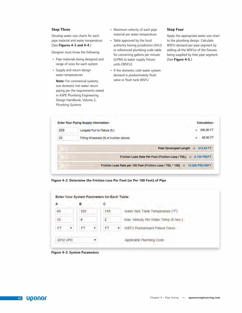
Chapter 4 – Pipe Sizing — uponorengineering.com40
Step Three
Develop water size charts for each pipe material and water temperature. (See Figures 4-3 and 4-4.)
Designer must know the following:
• Pipe materials being designed and range of sizes for each system
• Supply and return design water temperatures
Note: For commercial systems, size domestic hot-water return piping per the requirements stated in ASPE Plumbing Engineering Design Handbook, Volume 2, Plumbing Systems
• Maximum velocity of each pipe material per water temperature
• Table approved by the local authority having jurisdiction (AHJ) or referenced plumbing code table for converting gallons per minute (GPM) to water supply fixture units (WSFU)
• If the domestic cold-water system demand is predominately flush valve or flush tank WSFU
Step Four
Apply the appropriate water size chart to the plumbing design. Calculate WSFU demand per pipe segment by adding all the WSFUs of the fixtures being supplied by that pipe segment. (See Figure 4-5.)
Figure 4-3: System Parameters
Figure 4-2: Determine the Friction Loss Per Foot (or Per 100 Feet) of Pipe

Plumbing Design Assistance Manual — Chapter 4 – Pipe Sizing 41
15 FU
15 FU 15 FU
8 FU
8 FU 8 FU
8 FU 8 FU
45 FU 30 FU60 FU75 FUFlow
40 FU
2" CW 1½" CW 1½" CW 1¼" CW 1" CW1½" HW 1¼" HW 1¼" HW 1" HW ¾" HW
32 FU 24 FU 16 FU
15 FU 15 FU
Uponor AquaPEX Design Parameters
Domestic Cold-water Piping
• Maximum velocity of 12 ft./sec. through pipe
• Recommended velocity of 10 ft./sec. through pipe
Domestic Hot-water Piping
• Maximum velocity of 12 ft./sec. through pipe
• Recommended velocity of 8 ft./sec. through pipe
• Maximum operating temperature of 200°F (93.3°C)
Domestic Hot-water Return Piping
• Maximum velocity of 2 ft./sec. through pipe
• Max. operating temperature of 140°F (60°C)
• Sized per the requirements stated in ASPE Plumbing Engineering Design Handbook, Volume 2, Plumbing Systems
Figure 4-5: Apply Water Size Chart to Plumbing Design
Figure 4-4: Water Size Chart
Note: Uponor allows the dedicated fixture supply pipe to be of the same nominal size as the fixture being supplied, provided the dedicated pipe is no longer than 25 linear feet from a uniform-friction-loss-sized pipe.
Note: Uponor allows the use of ½" pipe for domestic hot-water return piping provided a flow-control device is in place to maintain velocities at or below 2 ft./sec. Refer to Table 5-8 on page 58 for appropriate flow rates at 2 ft./sec.
To determine the maximum velocities based on the use, geographical region and intended operating conditions for your specific project, contact Uponor Design Services at: U.S.: 888.594.7726 or [email protected] Canada: 888.994.7726 or [email protected]
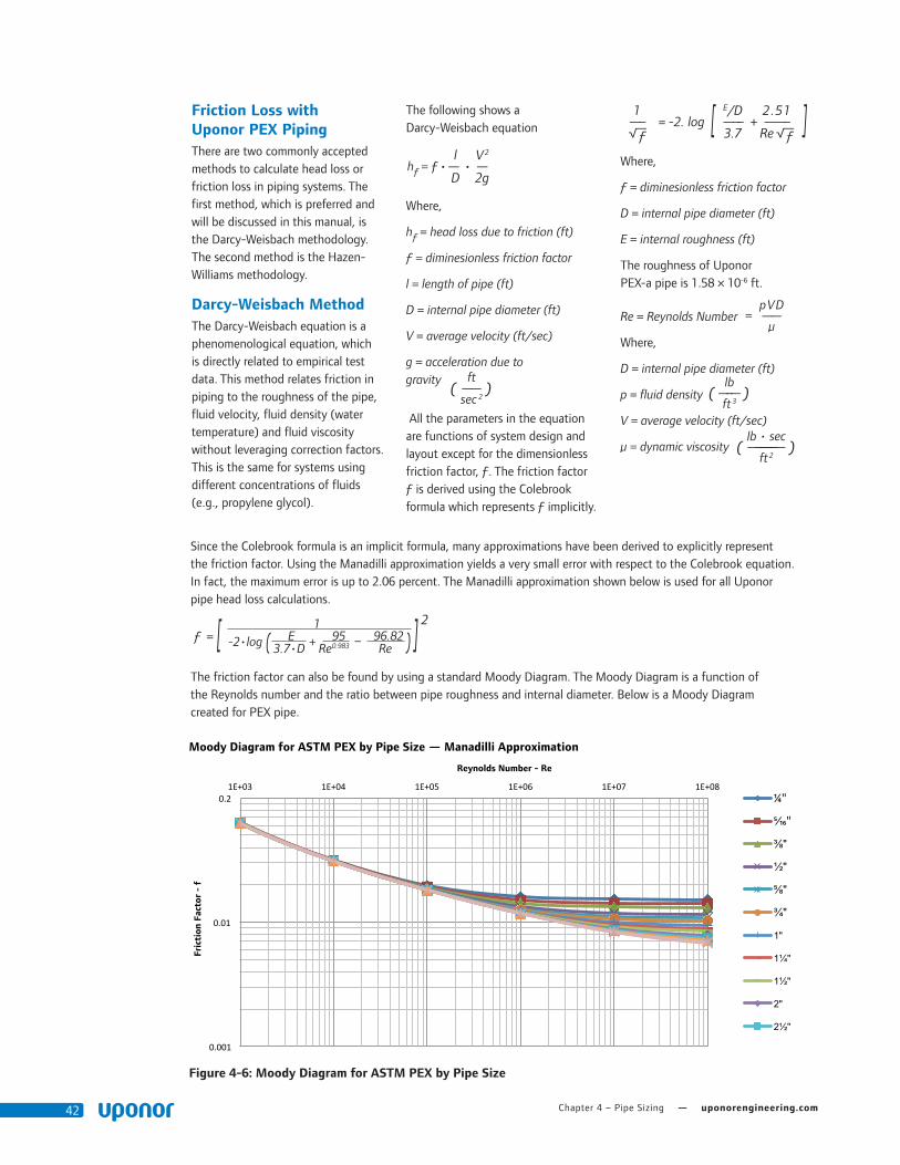
Chapter 4 – Pipe Sizing — uponorengineering.com42
Since the Colebrook formula is an implicit formula, many approximations have been derived to explicitly represent the friction factor. Using the Manadilli approximation yields a very small error with respect to the Colebrook equation. In fact, the maximum error is up to 2.06 percent. The Manadilli approximation shown below is used for all Uponor pipe head loss calculations.
ƒ = [ 1 1 ] 2
-2•log ( E + 95 – 96.82 )3.7•D Re0.983 Re
The friction factor can also be found by using a standard Moody Diagram. The Moody Diagram is a function of the Reynolds number and the ratio between pipe roughness and internal diameter. Below is a Moody Diagram created for PEX pipe.
Friction Loss with Uponor PEX PipingThere are two commonly accepted methods to calculate head loss or friction loss in piping systems. The first method, which is preferred and will be discussed in this manual, is the Darcy-Weisbach methodology. The second method is the Hazen-Williams methodology.
Darcy-Weisbach MethodThe Darcy-Weisbach equation is a phenomenological equation, which is directly related to empirical test data. This method relates friction in piping to the roughness of the pipe, fluid velocity, fluid density (water temperature) and fluid viscosity without leveraging correction factors. This is the same for systems using different concentrations of fluids (e.g., propylene glycol).
The following shows a Darcy-Weisbach equation
hƒ = ƒ l V2
•— • — D 2g
Where,
hƒ = head loss due to friction (ft)
ƒ = diminesionless friction factor
l = length of pipe (ft)
D = internal pipe diameter (ft)
V = average velocity (ft/sec)
g = acceleration due to gravity
All the parameters in the equation are functions of system design and layout except for the dimensionless friction factor, ƒ. The friction factor ƒ is derived using the Colebrook formula which represents ƒ implicitly.
1= -2. log [ E/D 2.51 ]—– —–– + ——–
√—ƒ 3.7 Re √—
ƒ
Where,
ƒ = diminesionless friction factor
D = internal pipe diameter (ft)
E = internal roughness (ft)
The roughness of Uponor PEX-a pipe is 1.58 × 10⁻⁶ ft.
Re = Reynolds Number
Where,
D = internal pipe diameter (ft)
p = fluid density
V = average velocity (ft/sec)
μ = dynamic viscosity
(ft
)—— sec 2
=pVD——
μ
(lb
)—–— ft 3
(lb • sec
)—–––––––— ft 2
• Text for Hydronic Design Process
The Uponor Hydronic Design Process
Sizing hydronic piping systems is often done in a very traditional manner by using head loss and velocity criteria to regulate flow rate. For example, many systems are designed around a given feet of head loss per 100-ft. of piping and maximum and minimum velocities. To properly size the pump we need to understand the cumulative flow rate of the piping system as well as the piping route that creates the maximum head loss criteria. When using a sizing philosophy that is regulated by feet of head loss per 100-ft. of piping many branches and sections of the piping system is oversized if they’re not on the path of most resistance.
The Uponor Design Services team can be an asset to help optimize the piping system. When designing a PEX based hydronic piping system, first the specified piping material in the design is traced to understand the system flow and head loss requirements.
0.001
0.01
0.21E+03 1E+04 1E+05 1E+06 1E+07 1E+08
Fric
tion
Fac
tor
- f
Reynolds Number - Re
Moody Diagram for ASTM PEX by Pipe Size — Manadilli Approximation
¼"
5⁄16"
⅜"
½"
⅝"
¾"
1"
1¼"
1½"
2"
2½"
Figure 4-6: Moody Diagram for ASTM PEX by Pipe Size

Plumbing Design Assistance Manual — Chapter 4 – Pipe Sizing 43
After finding the friction factor, incorporate it into the Darcy-Weisbach equation to calculate head loss in the pipe. This calculation method yields less than 1 percent error when compared to NSF empirical test data. The following graph shows the correlation between Uponor PEX friction loss using the Darcy-Weisbach method versus the NSF test data.
Hazen-Williams MethodThe Hazen-Williams method is another method for sizing PEX. However, it is not preferred by Uponor (especially for heating and cooling system sizing). Like the Darcy-Weisbach formula, this formulation is also based on empirical relationships with water flowing through pipes.
However, correlation with test data is much more limited. This formulation set was derived for fire sprinkler design and large water supply networks with 3" and larger piping. It is also strictly for 100 percent water and does not account for temperature and fluid viscosity.
Since its development, additional temperature correction and fluid correction factors have been established. However, results can show significant error when compared to test data.
The following equation shows the Hazen-Williams method.
100 1.852 q1.852
hƒ = 0.2083 • (–––––) • –––––––––C D4.8655
Where,ftwaterhƒ = head loss due to friction per 100 ft ( ––––––––––––– )100 ftpipe
C = Hazen-Williams roughness constant
The Hazen-Williams roughness constant for Uponor PEX-a is 163.
q = volumetric flow rate (gpm)
D = internal pipe diameter (in)
0
1
2
3
4
5
6
7
8
9
10
0.25 0.50 0.75 1.00 1.25 1.50 1.75 2.00 2.25 2.50 2.75 3.00
Pre
ssur
e D
iffe
rent
ial -
ft
Pipe Size - Nominal
Pressure Differential
NSF Test P (ft)
Calculated P (ft)
Figure 4-7: Friction Loss Comparing Darcy-Weisbach vs. NSF Test Data

Chapter 4 – Pipe Sizing — uponorengineering.com44
Comparing Darcy-Weisbach and Hazen-WilliamsNSF performed testing to calculate the friction loss of Uponor PEX pipe and Uponor ProPEX fittings. The testing allowed Uponor to analyze empirical test data and compare it with the Darcy-Weisbach and Hazen-Williams methods.
The following graph illustrates the comparison.
-10%
-5%
0%
5%
10%
15%
20%
25%
30%
0.0 0.5 1.0 1.5 2.0 2.5 3.0
Pipe Size - Nominal
Percent Error from Test Data
Darcy-Weisbach % Difference from Test
Darcy-Weisbach Average Error from Test
Hazen-Williams % Difference from Test
Hazen-Williams Average Error from Test
Friction Loss of Fittings There are two commonly accepted methods when analyzing pressure loss or head loss of fittings. The first and preferred method uses Cv values to precisely calculate fitting losses. The Cv value represents how many gallons per minute (gpm) can flow through a fitting at 1 psi pressure drop.
For example, a fitting with a Cv of 5.0 would flow 5.0 gpm at a 1 psi pressure drop across the fitting. Since Cv is a function of flow rate versus pressure drop, it yields an accurate representation of fitting friction loss.
The second method uses equivalent lengths. Uponor has created charts for both equivalent length and Cv. The equivalent lengths were developed using a flow velocity
of 8 fps.
The Y axis represents the percent error from the test data; the X axis represents nominal pipe size. The graph shows the average error when using the Darcy-Weisbach method is less than 1 percent when compared to the test data. The Hazen-Williams method, however, yields an 18 percent average error compared to the test data. Note: The test was performed with 70°F (21.1°C), 100 percent water.
Figure 4-8: Darcy-Weisbach and Hazen-Williams Comparison

Plumbing Design Assistance Manual — Chapter 4 – Pipe Sizing 45
The Cv Method for Calculating Friction LossCv is a function of flow rate versus pressure drop across the fitting. It also accounts for the density of the fluid.
Refer to the following friction loss calculation using the Cv method.
Pƒ F2
∆P = ( –––– ) ( ––––)Pw Cv
Where,
∆P = pressure drop across the fitting (psi)
lbPƒ = fluid denisty ( –––– )ft 3
lbPw = density of water at 60°F ( –––– )ft 3
The density of water at 60°F (15.6°C) is 62.38 pounds per cubic foot.
F = volumetric flow rate through the fitting (gpm)
Cv = known Cv rating of the fitting
This calculation yields a value in pounds per square inch which, for hydronic sizing, needs to be converted to feet of head as 100 percent water.
The conversion to feet of water is shown below.
144in 2 • ∆Phƒ = ––––––––––––––––1ft 3• Pƒ
Where,
hƒ = head loss due to friction across the fitting (ft)
lbPƒ = fluid denisty ( –––– )ft 3
∆P = pressure drop across the fitting (psi)
This value can be cumulatively added to the values from the other fittings in the distribution line to calculate the total loss for the fittings in the system.
Example 2
For a given elbow with a Cv of 6.7 and a flow rate of 3.5 gpm at a water temperature of 160°F (71.1°C), what is the friction loss of the fitting (in feet)?
Assuming the fluid is 100 percent water, here is the calculation.
lbPƒ = 60.99 ––––
ft 3
F = 3.5 gpm
Cv = 6.7
lb60.99 –––Pƒ F2
ft 3 3.5 gpm 2
∆P = ( ––– ) ( ––– ) = ( –––––––––– ) ( –––––––– ) = 0.267 psiPw Cw lb 6.762.38 –– –
ft 3
Note: To make the units work in the Cv formula, it must be assumed the Cv has the units of gpm and the result multiplied by 1 psi.
With the pressure differential known, the value found can be converted to head loss in feet as seen below.
144in 2 • ∆P 144in 2 • 0.267 psihƒ = –––––––––––– = –––––––––––––––––––– = 0.63 ft
1ft 2 • Pƒ lb1ft 2 •60.99 –– – ft 3
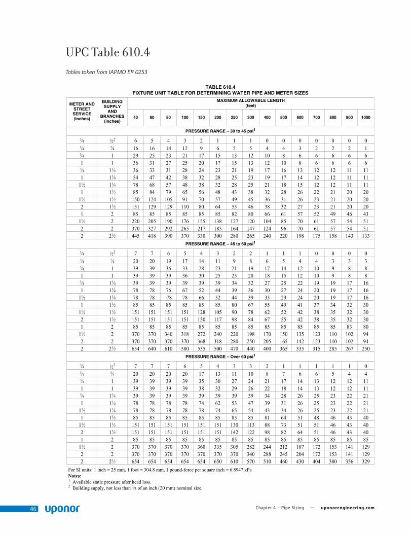
Chapter 4 – Pipe Sizing — uponorengineering.com46uniforM PluMbing Code
WaTer SuPPlY and diSTribuTion
106
For SI units: 1 inch = 25 mm, 1 foot = 304.8 mm, 1 pound-force per square inch = 6.8947 kPaNotes:1 Available static pressure after head loss.2 Building supply, not less than 3⁄4 of an inch (20 mm) nominal size.
Table 610.4fiXTure uniT Table for deTerMining WaTer PiPe and MeTer SizeS
MeTer andSTreeTServiCe(inches)
buildingSuPPlY
andbranCheS
(inches)
MaXiMuM alloWable lengTh(feet)
40 60 80 100 150 200 250 300 400 500 600 700 800 900 1000
PreSSure range – 30 to 45 psi1
3⁄4 1⁄22 6 5 4 3 2 1 1 1 0 0 0 0 0 0 03⁄4 3⁄4 16 16 14 12 9 6 5 5 4 4 3 2 2 2 13⁄4 1 29 25 23 21 17 15 13 12 10 8 6 6 6 6 61 1 36 31 27 25 20 17 15 13 12 10 8 6 6 6 63⁄4 11⁄4 36 33 31 28 24 23 21 19 17 16 13 12 12 11 111 11⁄4 54 47 42 38 32 28 25 23 19 17 14 12 12 11 11
11⁄2 11⁄4 78 68 57 48 38 32 28 25 21 18 15 12 12 11 111 11⁄2 85 84 79 65 56 48 43 38 32 28 26 22 21 20 20
11⁄2 11⁄2 150 124 105 91 70 57 49 45 36 31 26 23 21 20 202 11⁄2 151 129 129 110 80 64 53 46 38 32 27 23 21 20 201 2 85 85 85 85 85 85 82 80 66 61 57 52 49 46 43
11⁄2 2 220 205 190 176 155 138 127 120 104 85 70 61 57 54 512 2 370 327 292 265 217 185 164 147 124 96 70 61 57 54 512 21⁄2 445 418 390 370 330 300 280 265 240 220 198 175 158 143 133
PreSSure range – 46 to 60 psi1
3⁄4 1⁄22 7 7 6 5 4 3 2 2 1 1 1 0 0 0 03⁄4 3⁄4 20 20 19 17 14 11 9 8 6 5 4 4 3 3 33⁄4 1 39 39 36 33 28 23 21 19 17 14 12 10 9 8 81 1 39 39 39 36 30 25 23 20 18 15 12 10 9 8 83⁄4 11⁄4 39 39 39 39 39 39 34 32 27 25 22 19 19 17 161 11⁄4 78 78 76 67 52 44 39 36 30 27 24 20 19 17 16
11⁄2 11⁄4 78 78 78 78 66 52 44 39 33 29 24 20 19 17 161 11⁄2 85 85 85 85 85 85 80 67 55 49 41 37 34 32 30
11⁄2 11⁄2 151 151 151 151 128 105 90 78 62 52 42 38 35 32 302 11⁄2 151 151 151 151 150 117 98 84 67 55 42 38 35 32 301 2 85 85 85 85 85 85 85 85 85 85 85 85 85 83 80
11⁄2 2 370 370 340 318 272 240 220 198 170 150 135 123 110 102 942 2 370 370 370 370 368 318 280 250 205 165 142 123 110 102 942 21⁄2 654 640 610 580 535 500 470 440 400 365 335 315 285 267 250
PreSSure range – over 60 psi1
3⁄4 1⁄22 7 7 7 6 5 4 3 3 2 1 1 1 1 1 03⁄4 3⁄4 20 20 20 20 17 13 11 10 8 7 6 6 5 4 43⁄4 1 39 39 39 39 35 30 27 24 21 17 14 13 12 12 111 1 39 39 39 39 38 32 29 26 22 18 14 13 12 12 113⁄4 11⁄4 39 39 39 39 39 39 39 39 34 28 26 25 23 22 211 11⁄4 78 78 78 78 74 62 53 47 39 31 26 25 23 22 21
11⁄2 11⁄4 78 78 78 78 78 74 65 54 43 34 26 25 23 22 211 11⁄2 85 85 85 85 85 85 85 85 81 64 51 48 46 43 40
11⁄2 11⁄2 151 151 151 151 151 151 130 113 88 73 51 51 46 43 402 11⁄2 151 151 151 151 151 151 142 122 98 82 64 51 46 43 401 2 85 85 85 85 85 85 85 85 85 85 85 85 85 85 85
11⁄2 2 370 370 370 370 360 335 305 282 244 212 187 172 153 141 1292 2 370 370 370 370 370 370 370 340 288 245 204 172 153 141 1292 21⁄2 654 654 654 654 654 650 610 570 510 460 430 404 380 356 329
UPC Table 610.4 Tables taken from IAPMO ER 0253
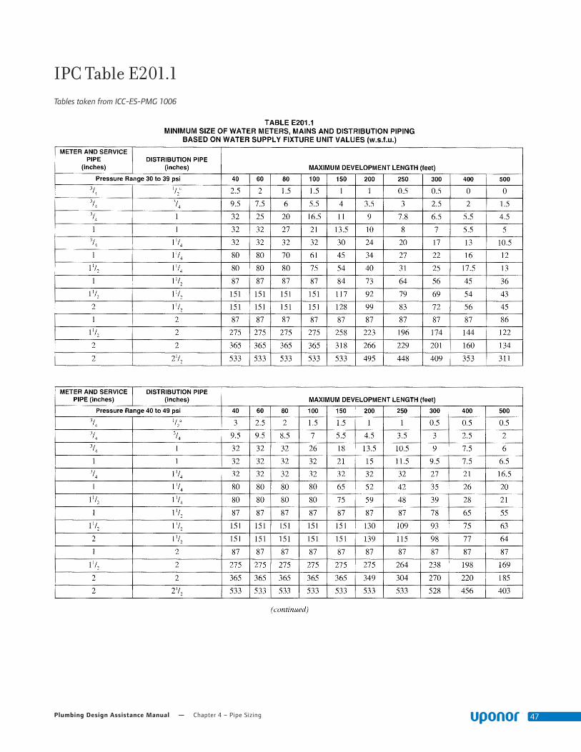
Plumbing Design Assistance Manual — Chapter 4 – Pipe Sizing 47
IPC Table E201.1 Tables taken from ICC-ES-PMG 1006
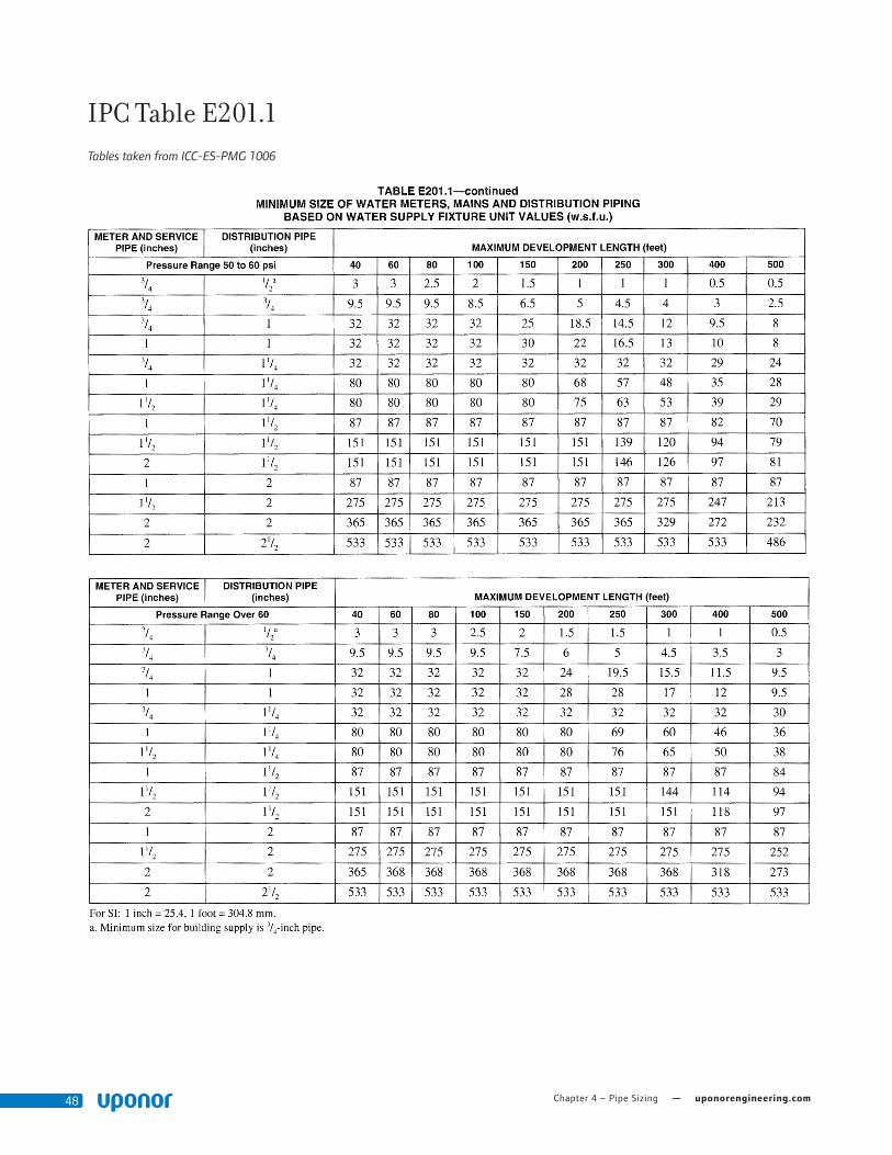
Chapter 4 – Pipe Sizing — uponorengineering.com48
IPC Table E201.1 Tables taken from ICC-ES-PMG 1006
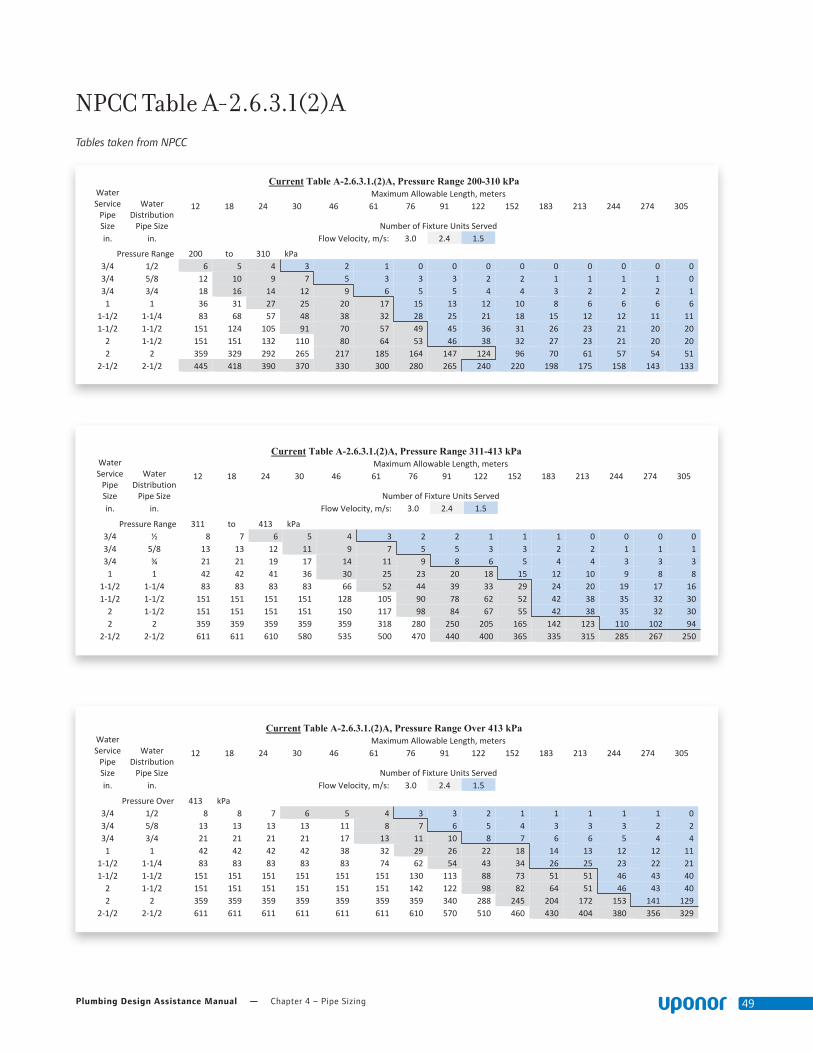
Plumbing Design Assistance Manual — Chapter 4 – Pipe Sizing 49
Addition of 3.65 m/s (12 fps) flow velocity to Table A-2.6.3.1.(2)A of the National Plumbing Code of Canada, 2010
Current Table A-2.6.3.1.(2)A, Pressure Range 200-310 kPa Water Service Pipe Size
Water Distribution Pipe Size
Maximum Allowable Length, meters 12 18 24 30 46 61 76 91 122 152 183 213 244 274 305
Number of Fixture Units Served in. in. Flow Velocity, m/s: 3.0 2.4 1.5
Pressure Range 200 to 310 kPa 3/4 1/2 6 5 4 3 2 1 0 0 0 0 0 0 0 0 0 3/4 5/8 12 10 9 7 5 3 3 3 2 2 1 1 1 1 0 3/4 3/4 18 16 14 12 9 6 5 5 4 4 3 2 2 2 1 1 1 36 31 27 25 20 17 15 13 12 10 8 6 6 6 6
1‐1/2 1‐1/4 83 68 57 48 38 32 28 25 21 18 15 12 12 11 11 1‐1/2 1‐1/2 151 124 105 91 70 57 49 45 36 31 26 23 21 20 20 2 1‐1/2 151 151 132 110 80 64 53 46 38 32 27 23 21 20 20 2 2 359 329 292 265 217 185 164 147 124 96 70 61 57 54 51
2‐1/2 2‐1/2 445 418 390 370 330 300 280 265 240 220 198 175 158 143 133
Modified Table A-2.6.3.1.(2)A, Pressure Range 200-310 kPa Water Service Pipe Size
Water Distribution Pipe Size
Maximum Allowable Length, meters 12 18 24 30 46 61 76 91 122 152 183 213 244 274 305
Number of Fixture Units Served in. in. Flow Velocity, m/s: 3.65 3.0 2.4 1.5
Pressure Range 200 to 310 kPa 3/4 1/2 6 5 4 3 2 1 0 0 0 0 0 0 0 0 0 3/4 5/8 12 10 9 7 5 3 3 3 2 2 1 1 1 1 0 3/4 3/4 18 16 14 12 9 6 5 5 4 4 3 2 2 2 1 1 1 42 31 27 25 20 17 15 13 12 10 8 6 6 6 6
1‐1/2 1‐1/4 89 68 57 48 38 32 28 25 21 18 15 12 12 11 11 1‐1/2 1‐1/2 163 125 105 91 70 57 49 45 36 31 26 23 21 20 20 2 1‐1/2 194 159 132 110 80 64 53 46 38 32 27 23 21 20 20 2 2 465 357 295 265 217 185 164 147 124 96 70 61 57 54 51
2‐1/2 2‐1/2 510 439 395 370 330 300 280 265 240 220 198 175 158 143 133
Page 3 of 8
NPCC Table A-2.6.3.1(2)ATables taken from NPCC
Current Table A-2.6.3.1.(2)A, Pressure Range 311-413 kPa Water Service Pipe Size
Water Distribution Pipe Size
Maximum Allowable Length, meters 12 18 24 30 46 61 76 91 122 152 183 213 244 274 305
Number of Fixture Units Served in. in. Flow Velocity, m/s: 3.0 2.4 1.5
Pressure Range 311 to 413 kPa 3/4 ½ 8 7 6 5 4 3 2 2 1 1 1 0 0 0 0 3/4 5/8 13 13 12 11 9 7 5 5 3 3 2 2 1 1 1 3/4 ¾ 21 21 19 17 14 11 9 8 6 5 4 4 3 3 3 1 1 42 42 41 36 30 25 23 20 18 15 12 10 9 8 8
1‐1/2 1‐1/4 83 83 83 83 66 52 44 39 33 29 24 20 19 17 16 1‐1/2 1‐1/2 151 151 151 151 128 105 90 78 62 52 42 38 35 32 30 2 1‐1/2 151 151 151 151 150 117 98 84 67 55 42 38 35 32 30 2 2 359 359 359 359 359 318 280 250 205 165 142 123 110 102 94
2‐1/2 2‐1/2 611 611 610 580 535 500 470 440 400 365 335 315 285 267 250
Modified Table A-2.6.3.1.(2)A, Pressure Range 311-413 kPa Water Service Pipe Size
Water Distribution Pipe Size
Maximum Allowable Length, meters 12 18 24 30 46 61 76 91 122 152 183 213 244 274 305
Number of Fixture Units Served in. in. Flow Velocity, m/s: 3.65 3.0 2.4 1.5
Pressure Range 311 to 413 kPa 3/4 ½ 10 7 6 5 4 3 2 2 1 1 1 0 0 0 0 3/4 5/8 19 18 14 11 9 7 5 5 3 3 2 2 1 1 1 3/4 ¾ 30 25 20 17 14 11 9 8 6 5 4 4 3 3 3 1 1 65 55 45 36 30 25 23 20 18 15 12 10 9 8 8
1‐1/2 1‐1/4 118 118 103 83 66 52 44 39 33 29 24 20 19 17 16 1‐1/2 1‐1/2 194 194 194 151 128 105 90 78 62 52 42 38 35 32 30 2 1‐1/2 194 194 194 194 150 117 98 84 67 55 42 38 35 32 30 2 2 429 429 429 429 359 318 280 250 205 165 142 123 110 102 94
2‐1/2 2‐1/2 797 733 663 614 535 500 470 440 400 365 335 315 285 267 250
Page 4 of 8
Current Table A-2.6.3.1.(2)A, Pressure Range Over 413 kPa Water Service Pipe Size
Water Distribution Pipe Size
Maximum Allowable Length, meters 12 18 24 30 46 61 76 91 122 152 183 213 244 274 305
Number of Fixture Units Served in. in. Flow Velocity, m/s: 3.0 2.4 1.5
Pressure Over 413 kPa 3/4 1/2 8 8 7 6 5 4 3 3 2 1 1 1 1 1 0 3/4 5/8 13 13 13 13 11 8 7 6 5 4 3 3 3 2 2 3/4 3/4 21 21 21 21 17 13 11 10 8 7 6 6 5 4 4 1 1 42 42 42 42 38 32 29 26 22 18 14 13 12 12 11
1‐1/2 1‐1/4 83 83 83 83 83 74 62 54 43 34 26 25 23 22 21 1‐1/2 1‐1/2 151 151 151 151 151 151 130 113 88 73 51 51 46 43 40 2 1‐1/2 151 151 151 151 151 151 142 122 98 82 64 51 46 43 40 2 2 359 359 359 359 359 359 359 340 288 245 204 172 153 141 129
2‐1/2 2‐1/2 611 611 611 611 611 611 610 570 510 460 430 404 380 356 329
Modified Table A-2.6.3.1.(2)A, Pressure Range Over 413 kPa Water Service Pipe Size
Water Distribution Pipe Size
Maximum Allowable Length, meters 12 18 24 30 46 61 76 91 122 152 183 213 244 274 305
Number of Fixture Units Served in. in. Flow Velocity, m/s: 3.65 3.0 2.4 1.5
Pressure Over 413 kPa 3/4 1/2 11 11 7 6 5 4 3 3 2 1 1 1 1 1 0 3/4 5/8 19 19 18 15 11 8 7 6 5 4 3 3 3 2 2 3/4 3/4 30 30 26 22 17 13 11 10 8 7 6 6 5 4 4 1 1 65 65 63 54 40 32 29 26 22 18 14 13 12 12 11
1‐1/2 1‐1/4 118 118 118 118 89 74 62 54 43 34 26 25 23 22 21 1‐1/2 1‐1/2 194 194 194 194 194 151 130 113 88 73 51 51 46 43 40 2 1‐1/2 194 194 194 194 194 169 142 122 98 82 64 51 46 43 40 2 2 429 429 429 429 429 429 391 340 288 245 204 172 153 141 129
2‐1/2 2‐1/2 797 797 797 797 728 651 610 570 510 460 430 404 380 356 329
Page 5 of 8
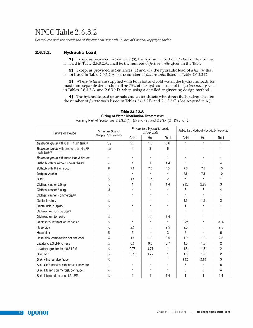
Chapter 4 – Pipe Sizing — uponorengineering.com50
NPCC Table 2.6.3.2 Reproduced with the permission of the National Research Council of Canada, copyright holder.
Division B 2.6.3.2.
2) Potable water systems shall be designed, fabricated and installed in accordancewith good engineering practice, such as that described in the ASHRAE Handbooksand ASPE Data Books. (See Appendix A.)
3) In one- and two-family dwelling units and manufactured homes, multi-purposesystems that combine potable water systems and residential fire sprinkler systems shallbe designed, fabricated and installed in accordance with NFPA 13D, “Installation ofSprinkler Systems in One- and Two-Family Dwellings and Manufactured Homes.”
2.6.3.2. Hydraulic Load
1) Except as provided in Sentence (3), the hydraulic load of a fixture or device thatis listed in Table 2.6.3.2.A. shall be the number of fixture units given in the Table.
2) Except as provided in Sentences (1) and (3), the hydraulic load of a fixture thatis not listed in Table 2.6.3.2.A. is the number of fixture units listed in Table 2.6.3.2.D.
3) Where fixtures are supplied with both hot and cold water, the hydraulic loads formaximum separate demands shall be 75% of the hydraulic load of the fixture units givenin Tables 2.6.3.2.A. and 2.6.3.2.D. when using a detailed engineering design method.
4) The hydraulic load of urinals and water closets with direct flush valves shall bethe number of fixture units listed in Tables 2.6.3.2.B. and 2.6.3.2.C. (See Appendix A.)
Table 2.6.3.2.A.Sizing of Water Distribution Systems(1)(2)
Forming Part of Sentences 2.6.3.2.(1), (2) and (3), and 2.6.3.4.(2), (3) and (5)
Private Use Hydraulic Load,fixture units Public Use Hydraulic Load, fixture units
Fixture or Device Minimum Size ofSupply Pipe, inches
Cold Hot Total Cold Hot Total
Bathroom group with 6 LPF flush tank(3) n/a 2.7 1.5 3.6 - - -
Bathroom group with greater than 6 LPFflush tank(3)
n/a 4 3 6 - - -
Bathroom group with more than 3 fixtures - - - (4) - - -
Bathtub with or without shower head ½ 1 1 1.4 3 3 4
Bathtub with ¾ inch spout ¾ 7.5 7.5 10 7.5 7.5 10
Bedpan washer 1 - - - 7.5 7.5 10
Bidet 3/8 1.5 1.5 2 - - -
Clothes washer 3.5 kg ½ 1 1 1.4 2.25 2.25 3
Clothes washer 6.8 kg ½ - - - 3 3 4
Clothes washer, commercial(5) - - - - - - -
Dental lavatory 3/8 - - - 1.5 1.5 2
Dental unit, cuspidor 3/8 - - - 1 - 1
Dishwasher, commercial(5) - - - - - - -
Dishwasher, domestic 3/8 - 1.4 1.4 - - -
Drinking fountain or water cooler 3/8 - - - 0.25 - 0.25
Hose bibb ½ 2.5 - 2.5 2.5 - 2.5
Hose bibb ¾ 3 - 3 6 - 6
Hose bibb, combination hot and cold ½ 1.9 1.9 2.5 1.9 1.9 2.5
Lavatory, 8.3 LPM or less 3/8 0.5 0.5 0.7 1.5 1.5 2
Lavatory, greater than 8.3 LPM 3/8 0.75 0.75 1 1.5 1.5 2
Sink, bar 3/8 0.75 0.75 1 1.5 1.5 2
Sink, clinic service faucet ½ - - - 2.25 2.25 3
Sink, clinic service with direct flush valve 1 - - - 6 - 6
Sink, kitchen commercial, per faucet ½ - - - 3 3 4
Sink, kitchen domestic, 8.3 LPM 3/8 1 1 1.4 1 1 1.4
National Plumbing Code of Canada 2010 Division B 2-49

Plumbing Design Assistance Manual — Chapter 4 – Pipe Sizing 51
NPCC Table 2.6.3.2 Reproduced with the permission of the National Research Council of Canada, copyright holder.
2.6.3.2. Division B
Table 2.6.3.2.A. (Continued)
Private Use Hydraulic Load,fixture units Public Use Hydraulic Load, fixture units
Fixture or Device Minimum Size ofSupply Pipe, inches
Cold Hot Total Cold Hot Total
Sink, kitchen domestic, greater than 8.3LPM
3/8 1.5 1.5 2 1.5 1.5 2
Sink, laboratory 3/8 - - - 1.5 1.5 2
Sink, laundry (1 or 2 compartments) 3/8 1 1 1.4 1 1 1.4
Sink, service or mop basin ½ - - - 2.25 2.25 3
Sink, washup, per faucet ½ - - - 1.5 1.5 2
Shower head, 9.5 LPM or less per head ½ 1 1 1.4 3 3 4
Shower head, greater than 9.5 LPM perhead
½ 1.5 1.5 2 3 3 4
Shower, spray, multi-head, fixture unit perhead
(5) 1 1 1.4 3 3 4
Urinal, with direct flush valve ¾ (6) - (6) (6) - (6)
Urinal, with flush tank 3/8 3 - 3 3 - 3
Urinal, with self-closing metering valve ½ 2 - 2 4 _ 4
Water closet, 6 LPF or less with flush tank 3/8 2.2 - 2.2 2.2 - 2.2
Water closet, greater than 6 LPF with flushtank
3/8 3 - 3 5 - 5
Water closet, with direct flush valve 1 (6) - (6) (6) - (6)
Notes to Table 2.6.3.2.A.:(1) The fixture unit values in this Table are not applicable in certain assembly occupancies because of surges in use by the occupants. For such
occupancies, refer to specific design information.(2) For fixtures not indicated in this Table, refer to Table 2.6.3.2.D.(3) Bathroom group is based on a ½-inch size bathtub supply pipe.(4) Add additional fixture to the fixture load for bathroom group.(5) Refer to manufacturer's recommendations.(6) For fixture unit values for fixtures with direct flush valves, see Sentence 2.6.3.2.(4) and Tables 2.6.3.2.B. and 2.6.3.2.C.
Table 2.6.3.2.B.Sizing of Water Distribution Systems for Urinals with Direct Flush Valves
Forming Part of Sentences 2.6.3.2.(4) and 2.6.3.4.(5)
Number of Valves Individual Fixture Unit Assigned inDecreasing Values Fixture Units in Accumulative Values(1)
1 20 20
2 15 35
3 10 45
4 8 53
5 or more 5 each 58, plus 5 for each additional fixture in excess of 5
Notes to Table 2.6.3.2.B.:(1) The accumulative fixture unit values are the total values to be used in conjunction with Table 2.6.3.2.A.
2-50 Division B National Plumbing Code of Canada 2010

Chapter 4 – Pipe Sizing — uponorengineering.com52
NPCC Table 2.6.3.2 Reproduced with the permission of the National Research Council of Canada, copyright holder.
Division B 2.6.3.4.
Table 2.6.3.2.C.Sizing of Water Distribution Systems for Water Closets with Direct Flush Valves
Forming Part of Sentences 2.6.3.2.(4) and 2.6.3.4.(5)
Number of Valves Individual Fixture Unit Assigned inDecreasing Values Fixture Units in Accumulative Values(1)
1 40 40
2 30 70
3 20 90
4 15 105
5 or more10 for each public use
and6 for each private use
115, plus 10 for each public useadditional fixture in excess of 5
and111, plus 6 for each private use additional
fixture in excess of 5
Notes to Table 2.6.3.2.C.:(1) The accumulative fixture unit values are the total values to be used in conjunction with Table 2.6.3.2.A.
Table 2.6.3.2.D.Hydraulic Loads of Fixtures Not Listed in Table 2.6.3.2.A.Forming Part of Sentences 2.6.3.2.(2) and (3) and 2.6.3.4.(5)
Hydraulic Load, fixture unitsSize of Supply Pipe, inches
Private Use Public Use3/8 1 2
½ 2 4
¾ 3 6
1 6 10
2.6.3.3. Static Pressure
1) Where the static pressure at any fixturemay exceed 550 kPa, a pressure-reducingvalve shall be installed to limit the maximum static pressure at the fixture to 550 kPa.
2.6.3.4. Size
1) Every water service pipe shall be sized according to the peak demand flow butshall not be less than ¾ inch size.
2) Except as provided in Sentence (3), the size of a supply pipe that serves a fixtureshall conform to Table 2.6.3.2.A.
3) For fixtures listed in Table 2.6.3.2.A. that have a permitted supply pipe size of3/8 inch, a connector not more than 750 mm long and not less than 6.3 mm insidediameter may be used to supply water to the fixture.
4) No water system between the point of connection with the water service pipe orthe water meter and the first branch that supplies a water heater that serves more thanone fixture shall be sized less than ¾ inch.
5) Where both hot and cold water is supplied to fixtures in residential buildingscontaining one or two dwelling units or row houses with separate water service pipes, thewater system may be sized in accordance with Table 2.6.3.4., where
a) the hydraulic loads for maximum separate demands on water distributionsystem piping are not less than 100% of the total hydraulic load of the fixtureunits given in Tables 2.6.3.2.A., 2.6.3.2.B., 2.6.3.2.C. or 2.6.3.2.D. for privateuse,
b) the minimum water pressure at the entry to the building is 200 kPa, andc) the total maximum length of water system is 90 m.
(See Appendix A.)
National Plumbing Code of Canada 2010 Division B 2-51

Plumbing Design Assistance Manual — Chapter 5 – System Design and Layout 53
Chapter 5:
System Design and Layout
This section profiles potable-water design and layout techniques that are primarily found in multi-family and commercial buildings, generally referred to as fire-resistant construction buildings, where both plumbing and building codes apply.
The Uponor AdvantageDesigning a building’s domestic-water system with Uponor AquaPEX piping and ProPEX fittings delivers a system with many advantages: reliability, cost-effectiveness and code-compliance from a system that meets peak flow demands while conserving water and energy.
Utilizing the smaller inside diameter of SDR9 Uponor PEX piping allows decreased system volume, therefore providing hot water to fixtures in a shorter amount of time
while still meeting end-use fixture requirements. The superior qualities of Uponor PEX deliver a lifetime of corrosion-free system performance.
Designing with multiport tees and small-dimension (½" to 1") coiled piping reduces the number of behind-the-wall connections in a unit application by 70 percent. Fewer connections mean faster installation times and fewer potential leak points.
Additional features such as a resistance to freeze damage, heat-kink repairability, stable material cost, superior thermal and acoustical properties, and a 25-year limited warranty give the designer additional confidence in choosing an Uponor AquaPEX Plumbing System.
Unit/In-suite PipingUponor AquaPEX pipe for distributing water to fixtures may be installed overhead, through framing, in slab or below grade. Common design methods for unit piping in multi-family commercial buildings include:
• Trunk and branch
• Home run
• Uponor Logic
Figure 5-1: Uponor PEX-a Pipe Support
Figure 5-2: In-wall Piping

Chapter 5 – System Design and Layout — uponorengineering.com54
Uponor Logic
Number of Fittings 9
Number of Connections 33
Nominal Pipe Size Length (ft)
½" 261
¾" 38
1" 5
Total 304
Home Run
Number of Fittings 7
Number of Connections 27
Nominal Pipe Size Length (ft)
½" 475
¾" 30
1" 5
Total 510
Uponor Logic PlumbingUponor Logic is the smart way to plumb, using flexible Uponor PEX pipe and multiport tees to minimize connections and maximize system performance. With an Uponor Logic layout, plumbing systems typically require fewer fittings than a trunk and branch design and less pipe than a home run layout.
Uponor Logic Layout
Home Run Layout
Critical Path = HWS - W.H. to Tub UPC Tub = 4 wsfu = 4 gpm CWS = 60°F HWS = 120°F Mixed = 110°F Hot-water Multiplier = 0.83 = 3.32 gpm
System Type
I.D. (in.) Distance (ft.) Volume (gal.)Velocity (ft./sec.)
Pressure Loss (psi)First-use
HW Time-to-fixture1⁄2" 3⁄4" 1⁄2" 3⁄4" 1⁄2" 3⁄4" Total 1⁄2" 3⁄4" 1⁄2" 3⁄4" Total Critical Path - Tub Only
Copper T & B 0.527 0.745 13 33 0.147 0.746 0.893 4.8 2.43 1.22 0.561 1.781 16.1 sec.
Home Run 0.475 0.671 32 9 0.294 0.165 0.459 5.8 3 4.16 0.252 4.412 8.3 sec.
Uponor Logic 0.475 0.671 19 17 0.174 0.312 0.486 5.8 3 2.47 0.476 2.946 8.7 sec.
Table 5-1: Uponor Logic Pipe and Fittings Usage
Figure 5-3: Uponor Logic Layout
Table 5-3: Performance Comparisons
Table 5-2: Home Run Pipe and Fittings Usage
Figure 5-4: Home Run Layout

Plumbing Design Assistance Manual — Chapter 5 – System Design and Layout 55
Copper Trunk and Branch
Number of Fittings 39
Number of Connections 93
Nominal Pipe Size Length (ft)
1⁄2" 234
3⁄4" 73
1" 5
Total 312
Copper Trunk and Branch Layout
0
10
20
30
40
Fittings
Copper T&B
Home Run
Uponor Logic
0 10 20 30 40 50 60 70 80 90
100
Connections
0
100
200
300
400
500
600
Feet of Pipe
Copper T&B
Home Run
Uponor Logic
Copper T&B
Home Run
Uponor Logic
Efficiencies of Uponor LogicFor unit and in-suite applications, Uponor Logic reduces the number of fittings by up to 70 percent when compared to copper trunk and branch and requires 40 percent less tubing than a home run system. Uponor offers a full line of EP multiport tees for ultimate design flexibility.
Hot-water PerformanceUponor Logic delivers hot water nearly 46 percent faster than a copper trunk and branch system for the first-use fixture and nearly 43 percent faster than a home run system for the second-use fixture.
Table 5-4: Copper Trunk and Branch Pipe and Fittings Usage
Figure 5-5: Copper Trunk and Branch Layout
System Type
First Use HW Time to Fixture
Second Use HW Time to Fixture
Critical Path-Tub Only Critical Path-Lav Only
Copper T & B 16.1 sec. 4.2 sec.
Home Run 8.3 sec. 7.5 sec.
Uponor Logic 8.7 sec. 4.3 sec.
Table 5-5: Hot Water Time-to-fixture Comparisons
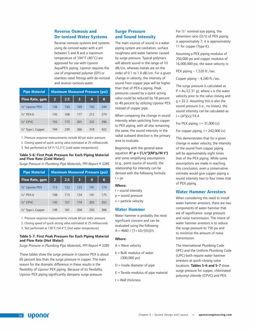
Chapter 5 – System Design and Layout — uponorengineering.com56
Reverse Osmosis and De-ionized Water SystemsReverse-osmosis systems and systems using de-ionized water with a pH between 5 and 8 and a maximum temperature of 104°F (40°C) are approved for use with Uponor AquaPEX piping. Uponor requires the use of engineered polymer (EP) or stainless-steel fittings with de-ionized and reverse-osmosis water.
Surge Pressure and Sound IntensityThe main sources of sound in a water piping system are cavitation, surface roughness and water hammer caused by surge pressure. Typical polymers will absorb sound in the range of 10 dB/cm, whereas metals are on the order of 0.1 to 1.0 dB/cm. For a given change in velocity, the intensity of sound from copper pipe will be higher than that of PEX-a piping. Peak pressures caused by a quick-acting valve could be reduced by 18 percent to 40 percent by utilizing Uponor PEX instead of copper pipe.
When comparing the change in sound intensity when switching from copper to PEX piping, with all else remaining the same, the sound intensity in the radial outward direction is the primary area to evaluate.
Beginning with the general wave equation ² p = (1/c²)(M²p/M t²) and some simplifying assumptions (e.g., point source of sound), the relationship for intensity can be derived with the following formula: I = pv
Where: I = sound intensity p = sound pressure
v = particle velocity
Water HammerWater hammer is probably the most significant concern and can be evaluated using the following: A = 4660 / [1+ kD/(Et)]½
Where:
A = Wave velocity
k = Bulk modulus of water (300,000 psi)
D = Inside diameter of pipe
E = Tensile modulus of pipe material
t = Wall thickness
For ½" nominal size piping, the dimension ratio (D/t) of PEX piping is approximately 7; it is approximately 11 for copper (Type K).
Assuming a PEX piping modulus of 250,000 psi and copper modulus of 16,000,000 psi, the wave velocity is:
PEX piping – 1,520 ft./sec.
Copper piping – 4,240 ft./sec.
The surge pressure is calculated as P = Av/(2.31 g), where v is the water velocity prior to the valve closing and g = 32.2. Assuming this is also the sound pressure (i.e., no losses), the sound intensity can be calculated as: I = (A²)(v)/74.4
For PEX piping, I = 31,000 (v)
For copper piping, I = 242,000 (v)
This demonstrates that for a given change in water velocity, the intensity of the sound from copper piping will be approximately eight times that of the PEX piping. While some assumptions are made in reaching this conclusion, even a conservative estimate would give copper piping a sound intensity two to four times that of PEX piping.
Water Hammer ArrestorsWhen considering the need to install water hammer arrestors, there are two components of water hammer that are of significance: surge pressure and noise transmission. The intent of water hammer arrestors is to reduce the surge pressure to 150 psi and to minimize the amount of noise transmission.
The International Plumbing Code (IPC) and the Uniform Plumbing Code (UPC) both require water hammer arrestors at quick-closing valve locations. Tables 5-6 and 5-7 show surge pressure for copper, chlorinated polyvinyl chloride (CPVC) and PEX.
Pipe Material Maximum Measured Pressure (psi)
Flow Rate, gpm 2 2.5 3 4 6
½" Uponor PEX 136 150 169 193 244
½" PEX-b 143 168 177 212 274
½" CPVC 155 173 201 222 296
½" Type L Copper 194 239 266 318 422
1. Pressure response measurements include 60 psi static pressure.
2. Closing speed of quick-acting valve estimated at 25 milliseconds.
3. Test performed at 54˚F/12.2°C (cold water temperature).
Table 5-6: First Peak Pressure for Each Piping Material and Flow Rate (Cold Water)Surge Pressure in Plumbing Pipe Materials, PPI Report # 3285
Pipe Material Maximum Measured Pressure (psi)
Flow Rate, gpm 2 2.5 3 4 6
½" Uponor PEX 113 122 123 141 174
½" PEX-b 108 113 124 141 175
½" CPVC 142 157 174 203 252
½" Type L Copper 149 181 204 250 306
1. Pressure response measurements include 60 psi static pressure.
2. Closing speed of quick-acting valve estimated at 25 milliseconds.
3. Test performed at 130˚F/54.4°C (hot water temperature).
Table 5-7: First Peak Pressure for Each Piping Material and Flow Rate (Hot Water)Surge Pressure in Plumbing Pipe Materials, PPI Report # 3285
These tables show the surge pressure in Uponor PEX is about 65 percent less than the surge pressure in copper. The main reason for the dramatic difference in these results is the flexibility of Uponor PEX piping. Because of its flexibility, Uponor PEX piping significantly dampens surge pressure.

Plumbing Design Assistance Manual — Chapter 5 – System Design and Layout 57
Hot-water System DesignUponor AquaPEX piping is tested and listed to PEX 5106 NSF-pw (CL5). Per ASTM F876, the CL5 chlorine resistance rating is intended for an end-use condition of 100 percent at 140°F/60°C, which is the highest chlorine-resistance rating available through ASTM. Products marked with a '5' in the first digit of the four-digit code and also bearing the CL5 designation [e.g., PEX 5106 NSF-pw (CL5)] indicate the product is approved for use in continuous, domestic, hot-water circulation systems with up to 140°F/60°C water temperatures.
Uponor requires that the velocity of the recirculation piping shall not exceed 2 ft./sec. and that the hot-water piping system (which includes the recirculation lines) meets the
following requirements stated in the ASPE Plumbing Engineering Design Handbook, Volume 2, Plumbing Systems:
1. Calculate the heat loss rates of the hot-water supply piping.
2. Calculate the heat loss rates of the hot-water circulating piping.
3. Calculate the circulation rates for all parts of the circulating piping and the total circulation rate required.
4. Determine the allowable uniform friction head loss and the total head required to overcome friction losses in the piping when the water is flowing at the required circulation rate.
5. Calculate the rates of flow for various piping sizes that will give the uniform pressure drop
established in Step 4, and tabulate the results.
6. Size the system based upon the tabulation set up in Step 5.
7. With the sizes established in Step 6, repeat Steps 2 through 6 as a check on the assumptions made.
While Uponor recommends the more accurate process above, the following streamlined method is also available:
1. Allow ½ gpm for each small hot- water riser (¾" to 1"), 1 gpm for each medium-sized hot-water riser (1¼" to 1½"), and 2 gpm for each large-sized hot-water riser (2" and larger).
2. Add 1 gpm for each group of 20 hot-water-supplied fixtures.
Water hammer arrestor where required by code (exact locations vary by manufacturer)
Isolation ball valve (typical)
Bend support(½" to ¾" typical)
Vent pipe
Wastepipe
Urinal carrier behind
Copper stub
Uponor AquaPEX pipeheader (size varies)
Stud wall assembly
Uponor ProPEX EP Tee
Support
Uponor AquaPEX pipe supply (size varies)
Copper carrier bracket
Water closet carrier
Commercial Flush Bank Detail
Figure 5-6: Commercial Flush Bank

Chapter 5 – System Design and Layout — uponorengineering.com58
Recirculated Hot-water SystemsTo maintain satisfactory temperatures, hot-water systems are often recirculated. Several recirculating methods are available:
• Manual control — Should be used only when hot water is needed 24 hours a day. If that is not the case, manual control is not cost-effective.
• Thermostatic aquastat — Used to shut off the pump during peak demands of hot water when circulation is not needed.
• Timed — Utilized during specific hours of operation when people are most likely to use hot-water fixtures.
• Combination aquastat/timed — Combines the capabilities of the aquastat system with timed control, reducing energy consumption.
Uponor AquaPEX is rated for use in continuous-circulation domestic water systems with temperatures up to 140°F/60°C.
Balancing of Recirculated Hot-water SystemsCirculated hot-water systems require balancing to maintain satisfactory system temperatures. If systems are not properly balanced, circulated water has the tendency to short circuit through the shortest loop in the system, thus creating high velocities in that loop and resulting
in hot water delays to remote loops. Hot water recirculated lines should be insulated, and they typically require little flow to maintain satisfactory system temperatures. Uponor limits maximum velocity of 2 ft./sec. in hot water return piping that uses Uponor AquaPEX. (See Table 5-8.)
Typical balancing solutions can incorporate factory pre-set flow control devices or flow regulating valves, which can be adjusted to the proper setting with measuring devices.
Heat TraceUponor approves the use of heat-trace cables with Uponor PEX products, provided the product has automatic thermostatic control capability and the temperature does not exceed the maximum rating listed on the piping (200ºF/93.3ºC). Wrap heat tape around the piping and secure with zip or cable ties, not tape; then insulate with either closed-cell or fiberglass pipe insulation.
Thermal ConductivityUponor PEX pipe has a very low coefficient of thermal conductivity: 0.219 Btu/(h•ft•ºF). In comparison, copper has a coefficient of thermal conductivity between 173 and 231 Btu/(h•ft•ºF), depending on wall thickness (Type K, L or M). Therefore, Uponor PEX piping does not sweat like copper.
Uponor PEX has superior insulating qualities when compared to copper
in the same application. Even though the difference in R-value is relatively small, the higher R-value of Uponor PEX piping will always result in less heat loss than with the same nominal- size copper pipe.
When comparing samples of the same thickness, CPVC has a lower thermal conductivity than Uponor PEX. To represent these values in the form of a pipe wall, we must compare the conductivity through a CTS SDR9 Uponor PEX pipe wall to that of a CTS SDR11 CPVC wall; SDR9 is 22 percent thicker than SDR11.
When conductivity is applied to the pipe wall thickness, Uponor PEX is within two (2) percent of the thermal resistance of CPVC.
InsulationBest practice is to insulate all domestic hot-water supply and return piping as well as any hydronic heating and cooling piping to conserve energy and maintain desired fluid temperature. Uponor also recommends insulating any piping installed in an unconditioned space or poorly ventilated areas with excessive moisture content. Always comply with local and energy codes.
Nominal Pipe Size
Velocity (ft/sec)
Flow Rate (gpm)
Friction Loss per Foot at 120ºF/48.9ºC
1⁄2" 2 1.1 0.0195
3⁄4" 2 2.2 0.0126
1" 2 3.6 0.0092
11⁄4" 2 5.4 0.0072
11⁄2" 2 7.5 0.0059
2" 2 12.9 0.0042
21⁄2" 2 19.8 0.0033
3" 2 28.1 0.0026
Table 5-8: Uponor AquaPEX Flow Rates at 2 ft./sec.
Pipe Btu/(h•ft•ºF)
Copper 173-231
PEX-a 0.219
CPVC 0.079
Table 5-10: Thermal Conductivity of Piping Materials
Nominal Pipe Size R-value
1⁄2" 0.03
3⁄4" 0.04
1" 0.052
11⁄4" 0.063
11⁄2" 0.075
2" 0.098
21⁄2" 0.122
3" 0.144
Table 5-9: SDR9 PEX R-value

Plumbing Design Assistance Manual — Chapter 5 – System Design and Layout 59
Pre-insulated Uponor AquaPEX PipingPre-insulated Uponor AquaPEX piping, which is available in coils or straight lengths, features closed-cell polyethylene insulation to make hot and cold potable-water distribution systems more efficient. The insulation can also help meet energy-code requirements; check with local
code authorities regarding energy-code requirements for specific applications.
Pre-insulated Uponor AquaPEX is available in the following sizes:
• ½" to 2" with ½"-thick insulation
• ½" to 1¼" with 1"-thick insulation
• 1½" to 2" with 1½"-thick insulation
Note: When using Pre-insulated Uponor AquaPEX in direct-burial applications, Uponor recommends using a minimum 1"-thick insulation due to soil compression forces.
Uponor PEX vs. Copper Heat Loss Comparison — Btu/(hr•ft)
Delta T (°F) 20 40 60 80 100
Insulation Thickness (K=0.24)
0" 1⁄2" 1" 11⁄2" 0" 1⁄2" 1" 11⁄2" 0" 1⁄2" 1" 11⁄2" 0" 1⁄2" 1" 11⁄2" 0" 1⁄2" 1" 11⁄2"
Nom
inal
Pip
e Si
zes
½"Uponor PEX 5.44 2.22 1.63 1.37 10.89 4.44 3.25 2.74 16.33 6.65 4.88 4.10 21.78 8.87 6.51 5.47 27.22 11.09 8.13 6.84
Type L Copper 5.76 2.24 1.63 1.37 11.52 4.47 3.27 2.74 17.27 6.71 4.90 4.11 23.03 8.95 6.53 5.48 28.79 11.18 8.16 6.85
¾"Uponor PEX 7.48 2.73 1.95 1.61 14.96 5.47 3.89 3.21 22.44 8.20 5.84 4.82 29.92 10.94 7.78 6.43 37.40 13.67 9.73 8.03
Type L Copper 8.06 2.77 1.96 1.61 16.12 5.54 3.91 3.22 24.18 8.31 5.87 4.84 32.25 11.07 7.83 6.45 40.31 13.84 9.78 8.06
1"Uponor PEX 9.42 3.23 2.25 1.83 18.85 6.47 4.50 3.66 28.27 9.70 6.75 5.49 37.69 12.93 8.99 7.33 47.11 16.17 11.24 9.16
Type L Copper 10.36 3.29 2.27 1.84 20.73 6.58 4.53 3.68 31.09 9.86 6.80 5.52 41.46 13.15 9.06 7.36 51.82 16.44 11.33 9.20
1¼"Uponor PEX 11.29 3.72 2.54 2.05 22.58 7.44 5.08 4.09 33.87 11.16 7.63 6.14 45.16 14.88 10.17 8.19 56.45 18.60 12.71 10.24
Type L Copper 12.67 3.80 2.57 2.06 25.34 7.60 5.14 4.12 38.00 11.40 7.70 6.18 50.67 15.20 10.27 8.24 63.34 19.00 12.84 10.30
1½"Uponor PEX 13.08 4.20 2.83 2.26 26.15 8.40 5.66 4.51 39.23 12.60 8.49 6.77 52.30 16.79 11.31 9.03 65.38 20.99 14.14 11.28
Type L Copper 14.97 4.31 2.86 2.27 29.94 8.61 5.73 4.55 44.91 12.92 8.59 6.82 59.89 17.23 11.45 9.10 74.86 21.53 14.32 11.37
2"Uponor PEX 16.46 5.13 3.39 2.66 32.93 10.27 6.77 5.33 49.39 15.40 10.16 7.99 65.85 20.54 13.55 10.65 82.31 25.67 16.94 13.32
Type L Copper 19.58 5.31 3.45 2.69 39.16 10.63 6.89 5.38 58.73 15.94 10.34 8.08 78.31 21.25 13.78 10.77 97.89 26.57 17.23 13.46
2½"Uponor PEX 19.30 5.92 3.92 3.00 38.60 11.85 7.84 6.01 57.90 17.77 11.76 9.01 77.20 23.69 15.68 12.01 96.50 29.61 19.60 15.01
Type L Copper 24.20 6.32 4.09 3.10 48.41 12.63 8.18 6.20 72.61 18.95 12.26 9.30 96.82 25.26 16.35 12.40 121.02 31.58 20.44 15.50
3"Uponor PEX 22.54 6.94 4.47 3.44 45.07 13.88 8.93 6.89 67.61 20.82 13.40 10.33 90.14 27.76 17.86 13.77 112.68 34.70 22.33 17.22
Type L Copper 28.79 7.31 4.59 3.50 57.58 14.62 9.17 7.01 86.37 21.93 13.76 10.51 115.16 29.24 18.35 14.01 143.95 36.55 22.93 17.51
Table 5-14: Uponor PEX vs. Copper Heat Loss Comparison — Btu/(hr•ft)
1. All calculations based on cylindrical thermal resistance methodology (ASPE/ASHRAE).
2. Based on fluid velocity of 8 ft./sec. at 160°F/71.1°C (maximizing heat transfer from 100% water).
3. Pipe convection set to be 1.761 Btu/hr•ft²•°F (based on standard value for free convection of air).
4. This heat loss comparison uses 0.24 Btu•in/(hr•ft2•°F) as the insulation thermal conductivity. This is a standard value for fiberglass pipe insulation at a 100°F/37.8°C mean temperature.
Pre-insulated PEX with ½" Insulation
Tubing Size
Insulation Thickness
R-valueHeat Loss at
70˚F Δ T
½" 0.6 (15mm) 3.9 7.4 Btu/(hr • ft)
¾" 0.6 (15mm) 3.6 9.0 Btu/(hr • ft)
1" 0.6 (15mm) 3.4 10.6 Btu/(hr • ft)
1¼" 0.6 (15mm) 3.3 12.1 Btu/(hr • ft)
1½" 0.6 (15mm) 3.2 13.6 Btu/(hr • ft)
2" 0.6 (15mm) 3.1 16.5 Btu/(hr • ft)
Table 5-11: Pre-insulated Uponor AquaPEX with ½" Polyethylene Insulation R-value/Heat Loss
Pre-insulated PEX with 1" Insulation
Tubing Size
Insulation Thickness
R-valueHeat Loss at
70˚F Δ T
½" 1.0 (25mm) 7.5 6.3 Btu/(hr • ft)
¾" 1.1 (28mm) 7.9 7.1 Btu/(hr • ft)
1" 1.0 (25mm) 6.4 8.8 Btu/(hr • ft)
1¼" 1.0 (25mm) 6.1 10.0 Btu/(hr • ft)
Table 5-12: Pre-insulated Uponor AquaPEX with 1" Polyethylene Insulation R-value/Heat Loss
Pre-insulated PEX with 1½" Insulation
Tubing Size
Insulation Thickness
R-valueHeat Loss at
70˚F Δ T
1½" 1.7 (42mm) 11.2 7.0 Btu/(hr • ft)
2" 1.6 (40m) 9.9 8.6 Btu/(hr • ft)
Table 5-13: Pre-insulated Uponor AquaPEX with 1½" Polyethylene Insulation R-value/Heat Loss
1 Pre-insulated Uponor AquaPEX consists of PEX-a pipe and closed cell, crosslinked polyethylene insulation with a thermal conductivity of 0.25 Btu•in/(hr•ft2•°F).

Chapter 5 – System Design and Layout — uponorengineering.com60
Uponor Ecoflex® Products
Ecoflex Potable PEXEcoflex Potable PEX features a single Uponor AquaPEX service pipe and is designed for potable-water distribution applications. The piping is surrounded by multi-layer, closed-cell, PEX-foam insulation and a water-resistant, corrugated, HDPE jacket, making it ideal for water service and other direct-burial applications. Ecoflex Potable PEX uses ProPEX fittings up to 3" or WIPEXTM fittings. For more information about Ecoflex, please refer to the Ecoflex Design and Installation Manual.
Ecoflex Potable PEX is available in the following sizes:
• 1" in coils up to 600 ft.
• 1¼" in coils up to 500 ft.
• 1½" to 3" in coils up to 300 ft.
• Longer and custom lengths are also available
Ecoflex Potable HDPEEcoflex Potable HDPE features a single high-density polyethylene (HDPE) service pipe in ASTM sizes. This pipe is the economical solution for pre-insulated distribution for chilled-water, cooling and low-temperature heating applications. The HDPE service pipe does not have an oxygen barrier, and it is manufactured in accordance with the following standards:
• PE 3408 or PE 4710
• ASTM D3035 or F714 C3
• AWWA C901 or C906
• NSF-61 and NSF-pw
The piping is surrounded by multi-layer, closed-cell, PEX-foam insulation and water-resistant, corrugated HDPE jacket, making it ideal for direct-burial applications.
Ecoflex Potable HDPE can use Uponor’s selection of HDPE fittings as well as standard SDR11 fittings from other manufacturers.
Ecoflex Potable HDPE is available in 300-foot coils in the following sizes:
• 1¼"
• 1½"
• 2"
• 3"
• 4"
• Longer and custom lengths are also available
Ecoflex Potable PlusEcoflex Potable Plus features Uponor AquaPEX piping with a self-regulating heating cable. The pipe and cable are surrounded by multi-layer, closed-cell, PEX-foam insulation and a water-resistant, corrugated, HDPE jacket, making it ideal for direct-burial applications.
Ecoflex Potable Plus is available in 1¼" pipe sizes with a 5.5" jacket or on a made-to-order basis. Contact Uponor Customer Service at 800.321.4739 (U.S.) or 888.994.7726 (Canada) for details.
Uponor Ecoflex Potable PEX
Uponor Ecoflex Potable HDPE
Uponor Ecoflex Potable Plus

Plumbing Design Assistance Manual — Chapter 5 – System Design and Layout 61
All piping systems expand and contract at different rates depending on material characteristics. PEX piping systems exhibit a higher expansion and contraction rate when subjected to changes in temperature as compared to metallic piping systems. Because of its lower modulus of elasticity, PEX is less rigid than metallic piping and develops less force than metallic pipe when exposed to temperature changes.
For this reason, Uponor PEX can be easily restrained by installing PEX-a Pipe Support. With proper strapping, PEX-a Pipe Support can lessen the need for numerous directional changes and expansion loops as the pipe will absorb much of the expansion stresses. Allowing for controlled expansion and contraction in multiple parts of a piping system is an accepted means of preventing added stresses in other parts of the system that could compromise system performance, damage the structural integrity of the piping components, or damage the structure that support the piping.
Including design elements to address changes in pipe length will redistribute the stresses that would otherwise result in uncontrolled thermal movement. According to Plastics Pipe Institute TR-21 Thermal Expansion and Contraction in Plastics Piping Systems, the design and installation of a plastic piping system often requires special attention to thermal expansion and contraction.
Free-body CoefficientThe free-body coefficient of expansion is a calculated, theoretical value in which all of the surfaces would be free of friction and contain no end or branch connections. The free-body coefficient of expansion for PEX-a piping is 1.1"/10˚F ΔT/100 ft. (27.94mm/5.56°C ΔT/30.48m). For a given change in temperature, the theoretical expansion and contraction can be easily calculated for a given length of piping. In practice, the free-body condition for installed piping is unlikely as all surfaces would need to be free of friction.
Installation of piping in the field requires supports, strapping and bracing that inherently apply friction to the pipe surfaces, therefore, restraining pipe movement. In addition, it takes much more time for PEX-a piping to reach temperature equilibrium due to its coefficient of thermal conductivity and wall thickness. Thermal expansion in PEX-a piping is more likely to occur in the middle temperature range than at the extremes produced by operating water temperatures. Therefore the free-body coefficient is a very conservative means of calculating pipe movements in installed conditions.
Test ValidationUponor has tested a variety of suspended PEX piping assemblies to determine which type of expansion solution works best for most applications. The results strongly support the use of PEX-a Pipe
Support in conjunction with fixed anchor points positioned every 65' for hot-water and every 150' for cold-water plumbing systems. Pipe runs installed in this manner experience 89 percent to 93 percent reduction in thermal expansion. The two scenarios outlined in Table 5-15 detail the installation of these pipe runs. The strut and strut clamps experienced the most reduction in expansion (93 percent) because of the snug grip and increased friction from pipe clamps yielding an effective expansion rate of 0.08"/10˚F ΔT/100 ft; clevis or loop type hangers offered an 89 percent reduction yielding an effective expansion rate of 0.12"/10˚F ΔT/100 ft. The thermal expansion rate for copper is 0.11"/10˚F ΔT/100 ft so using PEX-a Pipe Support with Uponor PEX makes the piping system perform very similarly to copper with respect to thermal expansion.
The highest force measured at fixed anchor points during these tests was 173 lbs., which is much less than the guided force of metallic piping. Properly braced fixed anchor points and commonly specified drop-in anchors, beam clamps or similar fastening components for metallic piping are of sufficient strength to support the PEX install.
Given the flexible nature of PEX pipe, a slight snaking pattern may be experienced even when PEX-a Pipe Support is utilized to control expansion. This is considered normal and does not affect the integrity of system. Pipe insulation can help to
Effects of Thermal Expansion with PEX-a Pipe Support
ScenarioWater
Temperature (°F)
Delta T (°F)Support Spacing
Anchor Spacing
Linear Expansion
Expansion Rate (inches
per 100' per 10°F ΔT)
Reduction vs. Bare
PEX
Strut and Strut Clamps
180 105 96" 65' ½" 0.08 93%
Loops and Clevis 175 100 96" 65' ¾" 0.12 89%
Table 5-15: Uponor PEX Thermal Expansion Test Results
Thermal Expansion and Contraction

Chapter 5 – System Design and Layout — uponorengineering.com62
Figure 5-7: Fixed Anchor Point
Two hole open short angle
Steel strut
All-threaded rod
Two hole open short angle
Strut clamp
Uponor PEX-a pipe
Steel strut or other approved device
minimize the aesthetics of a slight snake in the pipe run.
Ensure the piping layout, including anchors, adequately isolates joints, fittings and connections from high thrust or bending forces.
Uponor ProPEX connections have a very high resistance to pull-out forces when compared to other various joint types. The best solution for absorbing expansion and contraction in Uponor PEX piping systems is proper support and to build in flexibility. In applications where long piping runs may be exposed to large temperature changes, the resulting expansion and contraction must be absorbed by additional means such as expansion loops, arms and offsets or by restraining the pipe in a continuous run of PEX-a Pipe Support. Piping runs between anchors and expansion compensating devices must be periodically supported, at a spacing defined by code, with hangers or supports that allow for movement of the piping. The compensating device relieves axial stress in a straight run of piping by transferring it into a moderate bending stress, thereby absorbing the expansion stress.
Above-ground and Suspended ApplicationsIn single-family and low-rise residential applications, thermal expansion is generally not an issue due to the use of smaller-diameter piping that absorbs expansion and contraction forces due to the routing, supporting methods and flexible nature of Uponor PEX piping. Smaller diameter (3⁄8" to 1") pipe runs require an extra 1⁄8" to 3⁄16" of longitudinal clearance per foot of run. Do not allow piping to dip excessively between supports and do not pull piping tight during installation.
Larger suspended commercial systems are often designed to include a number of changes in direction. These directional changes can be a beneficial aspect in the piping system by creating a spring-like effect, which safely absorbs and controls thermal expansion and contraction.
Controlling Expansion in Hot-water SystemsBest practice for controlling expansion forces is to continuously restrain the pipe by installing Uponor PEX-a Pipe Support. Install PEX-a Pipe Support in accordance with
the installation guidelines on pages 80-84 in Chapter 6. For best results, terminate PEX-a Pipe Support segments only at fitting locations. Refer to Table 6-4 and Figure 6-9 on page 71 for minimum distance to fittings.
Proper use of strapping is critical when using this technique. Strapping shall be:
• Nylon coated stainless-steel with a minimum tensile rating of 300-lbs.
• Rated for operating temperature ranges, including high temperatures
• UV-resistant to withstand expected life of the piping system.
To account for expansion, fixed anchor points shall be used to restrict piping movement. Fixed anchor points shall be:
• Installed every 65 ft. (19.8m)
• Constructed with materials that provide rigidity (see Figure 5-7)
• Utilize a pipe clamp that will restrain piping material
• Installed within 18" of a fire-rated
wall penetration (see Figure 5-8)
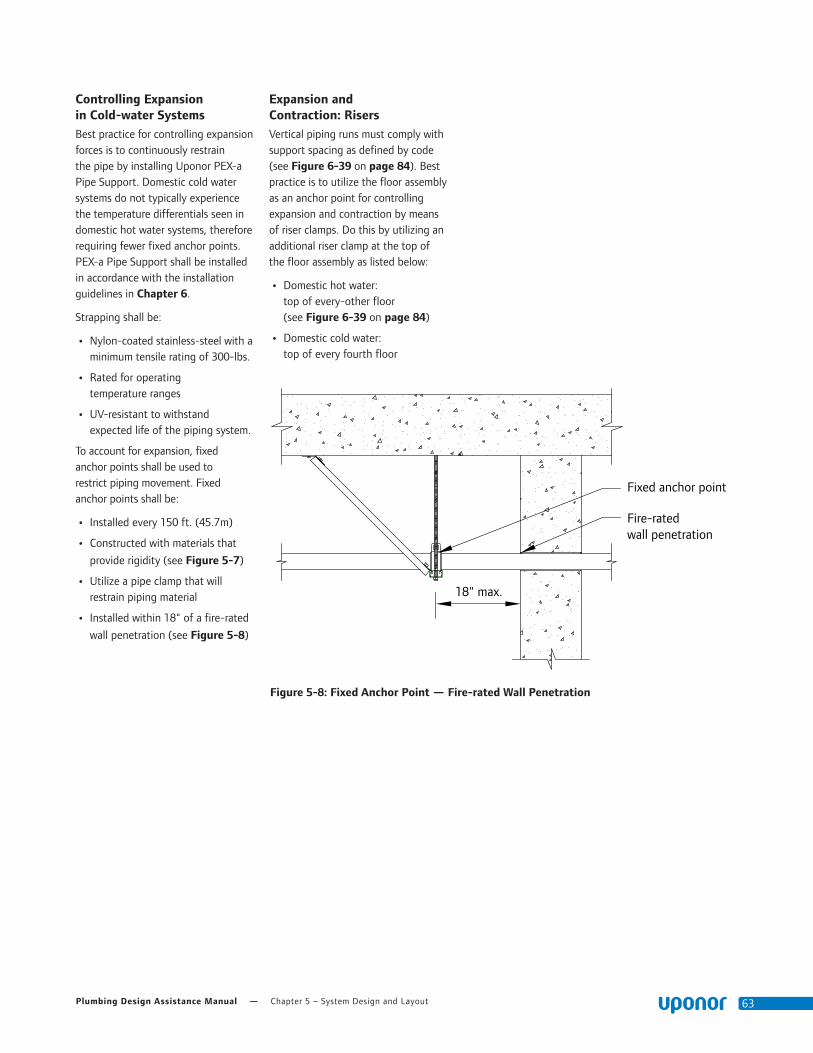
Plumbing Design Assistance Manual — Chapter 5 – System Design and Layout 63
Controlling Expansion in Cold-water SystemsBest practice for controlling expansion forces is to continuously restrain the pipe by installing Uponor PEX-a Pipe Support. Domestic cold water systems do not typically experience the temperature differentials seen in domestic hot water systems, therefore requiring fewer fixed anchor points. PEX-a Pipe Support shall be installed in accordance with the installation guidelines in Chapter 6.
Strapping shall be:
• Nylon-coated stainless-steel with a minimum tensile rating of 300-lbs.
• Rated for operating temperature ranges
• UV-resistant to withstand expected life of the piping system.
To account for expansion, fixed anchor points shall be used to restrict piping movement. Fixed anchor points shall be:
• Installed every 150 ft. (45.7m)
• Constructed with materials that
provide rigidity (see Figure 5-7)
• Utilize a pipe clamp that will restrain piping material
• Installed within 18" of a fire-rated
wall penetration (see Figure 5-8)
Expansion and Contraction: RisersVertical piping runs must comply with support spacing as defined by code (see Figure 6-39 on page 84). Best practice is to utilize the floor assembly as an anchor point for controlling expansion and contraction by means of riser clamps. Do this by utilizing an additional riser clamp at the top of the floor assembly as listed below:
• Domestic hot water: top of every-other floor (see Figure 6-39 on page 84)
• Domestic cold water: top of every fourth floor
Figure 5-8: Fixed Anchor Point — Fire-rated Wall Penetration
Fixed anchor point
Fire-rated wall penetration
18" max.

Chapter 5 – System Design and Layout — uponorengineering.com64
Expansion ArmThe flexible arm should be long enough to prevent damage, and support clamps should be placed far enough from the wall to allow for longitudinal thermal expansion (see Figure 5-9).
Use the formula below to calculate the minimum length of the expansion arm: LB = C x SQRT(D x ΔL)
Where:
• L is total distance of piping run from a fixed anchor point to a corner, or in the case of an expansion loop, from a fixed anchor point to a fixed anchor point.
• LB is the flexible arm in inches.
• C is the material constant (12 for PEX).
• D is the outside diameter of the piping.
• ΔL is the thermal-expansion length in inches.
Expansion Arm Example:
Uponor AquaPEX piping with an outside diameter of 1.625" is installed running a length of 75 ft. The hot water it carries is 120ºF/48.9ºC, and the ambient temperature is 60ºF/15.6ºC. Calculate the length of the flexible arm. PEX piping expands at a rate of 1.1" per 10°F temperature change per 100 ft. of piping (27.94mm per 5.56°C temperature change per 30.48m of piping).
LB = C x √(D x ΔL)
LB= 12 x √(1.625" x (1.1" x (60/10)/(100 ft./ L))))
LB = 12 x √(1.625" x 4.95")
LB = 12 x 2.84"
LB = 34.08"
The required arm length (LB) is 34.08" to prevent excessive stress on the fittings and support clamps.
For a list of calculated flexible arm lengths, refer to Appendix E.
Expansion LoopThe same equation applies for an expansion loop. However, the arm length (LB) must be divided into three sections using the following formula: LB = 5L1
Expansion Loop Example:
5L1 = 34.08"
L1 = 34.08/5
L1 = 6.82"
L2 = 2 L1
L2 = 13.63"
For a list of calculated expansion loop legs, refer to Appendix E.
Uponor offers a preformed 2" Uponor AquaPEX Expansion Joint (F8152000) and 2" Wirsbo hePEX Expansion Joint (A1992000) to make expansion joint installations more efficient. Both EP and brass elbows may be used with the preformed expansion loop.
Fixed anchor point
∆L/2L
∆L/2
L2 L2
L1
Fixed anchor point
Figure 5-10: Expansion LoopFigure 5-9: Expansion Arm
Fixed anchor point
Fixed anchor point
L ∆L
LB
Plumbing Design Assistance Manual — Chapter 5 – System Design and Layout 65
Thermal Expansion in Underground ApplicationsFor direct-burial applications, mitigate the effects of thermal expansion by incorporating proper installation techniques that provide adequate resistance to axial stress.
Per PPI TR-21 Thermal Expansion and Contraction in Plastic Piping Systems, a buried or concrete-encased pipe is effectively restrained against both lateral and axial movement by surrounding embedment material. The magnitude of the frictional restraining force is dependent on the nature of the soil and on installation and operating conditions. For example, the extent of compaction near the pipe can affect the quality of contact between the pipe and surrounding soil.
The anchoring or restraining effect of surrounding soil on pipe movement can be significantly augmented by external pipe geometry. Tees, lateral connections and changes in direction all help to anchor a pipe in the surrounding soil.
Because the friction between the pipe and surrounding material is generally sufficient to arrest axial pipe movement, a buried pipe that is subject to typical fluctuations in the temperature of the fluid it conveys or of the soil that surrounds it is only subject to modest axial thermal stresses that are well within the strength capabilities of the pipe.
The magnitude of the soil restraint, which acts on plastic pipe with an externally smooth wall, may be estimated from the following equation:
f = μ • N
Where:
f = Axial frictional resistance (lbs./inch of pipe length)
μ = Approximate coefficient of friction between soil and pipe and between concrete and pipe. A value of 0.1 is generally accepted as a conservative representation for the case where of smooth surface plastic pipe makes full contact with the embedment material
N = Normal soil pressure acting on 1" of width pipe (psi/inch)
N = π • Do • Soil pressure, where Do is the pipe outside diameter (inches)
An example of taking advantage of soil restraint is installing the piping in a snaking pattern and utilizing continuous runs to capitalize on the piping’s flexibility.

Chapter 5 – System Design and Layout — uponorengineering.com66

Plumbing Design Assistance Manual — Chapter 6 – Installation Methods 67
Chapter 6:
Installation Methods
This section profiles potable-water installation methods that are typical for commercial buildings to which both fire and building codes apply (generally referred to as fire-resistant construction buildings). Each method includes a detailed illustration with notes for installing potable-water piping in fire-resistant construction buildings.
For specific fire-assembly details, refer to Chapter 3.
Local Code ApprovalsBefore installing any piping, discuss the installation with local building and plumbing officials. While the Uponor Plumbing Systems described in this section meet the requirements of most building and plumbing codes found in the United States and Canada, some inspectors are not aware of these types of installations. Chapters 1 and 3 in this design manual provide supporting information and listings for United States and Canadian code compliance.
Storing and Handling PEXAlthough not comprehensive, the following highlights the most common guidelines when storing and handling Uponor AquaPEX.
• Do not store PEX piping outdoors.
• Keep PEX piping in the original packaging until the time of installation.
• Install Uponor systems according to the installation instructions. Failure to follow the instructions and installation guidelines in this manual can result in the failure of Uponor systems.
• Do not use Uponor AquaPEX piping where temperatures and pressures exceed ratings.
• Do not use or store Uponor AquaPEX White piping where it will be exposed to direct sunlight for more than 30 days.
• Do not use or store Uponor AquaPEX Red and Blue piping where it will be exposed to direct sunlight for more than 90 days.
• Do not weld, glue or use adhesives or adhesive tape with Uponor AquaPEX piping.
Note: You may temporarily affix adhesive tape to Uponor AquaPEX piping during installation. However, to protect the integrity of the system, the tape should not be permanent. Remove the tape and residual adhesive after completing the installation.
• Do not apply open flame to Uponor AquaPEX piping.
• Do not install Uponor AquaPEX piping within 6" of any gas appliance vents. One exception is double-wall B-vents, which have a minimum clearance of 1".
• Do not install Uponor AquaPEX piping within 12" of any recessed light fixture unless the PEX piping line is protected with suitable insulation or the fixture is Insulation Contact (I.C.) rated.
• Do not install Uponor AquaPEX within 5 ft. of direct view from fluorescent lighting without sleeving the pipe with a UV-blocking material.
• Do not use Uponor AquaPEX piping to convey natural gas.
• Do not solder, braze, weld or fusion-weld within 18" of any Uponor AquaPEX piping in the same water line. Make any heat-related connections prior to making the ProPEX connection.
• Do not install Uponor AquaPEX piping between the tub/shower valve and tub spout.
• Do not use Uponor AquaPEX piping for an electrical ground.
• Do not spray on or allow organic chemicals, strong acids or strong bases to come into contact with Uponor AquaPEX piping.
• Do not use petroleum or solvent-based paints, greases or sealants on Uponor AquaPEX piping.
• Use only approved and appropriate firestop materials with Uponor AquaPEX piping.
• Do not allow rodents, insects or other pests to come into contact with Uponor AquaPEX piping.
• Do not subject Uponor AquaPEX piping to blunt impact.
• Do not install Uponor AquaPEX piping in soil environments contaminated with solvents, fuels, organic compounds, pesticides or other detrimental materials that may cause permeation, corrosion, degradation or structural failure of the piping. In areas where such conditions are suspected, perform a chemical analysis of the soil or groundwater to ascertain the acceptability of Uponor AquaPEX piping for the specific installation. Check local codes for additional requirements.
• Do not press standard ProPEX brass fittings (i.e., copper press).
• Do not install Uponor AquaPEX pipe in steel-stud applications without the use of grommets to protect the pipe from abrasion.
Note: When transitioning from PEX to other piping materials, follow the appropriate installation instructions for that product.
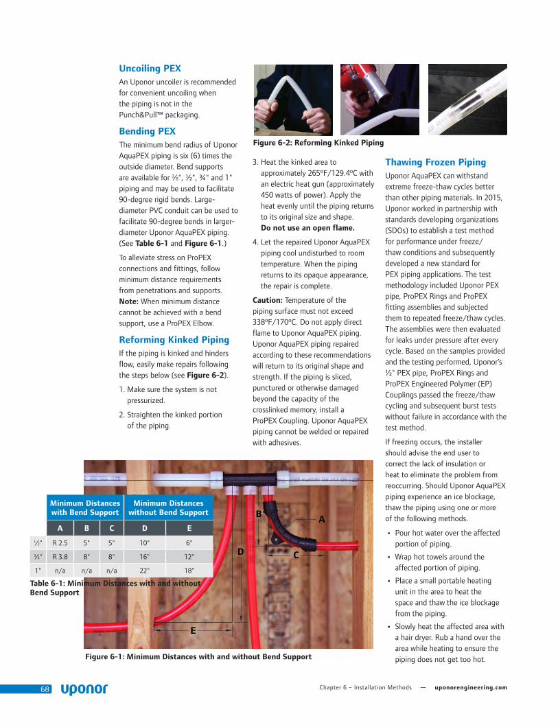
Chapter 6 – Installation Methods — uponorengineering.com68
3. Heat the kinked area to approximately 265ºF/129.4ºC with an electric heat gun (approximately 450 watts of power). Apply the heat evenly until the piping returns to its original size and shape. Do not use an open flame.
4. Let the repaired Uponor AquaPEX piping cool undisturbed to room temperature. When the piping returns to its opaque appearance, the repair is complete.
Caution: Temperature of the piping surface must not exceed 338ºF/170ºC. Do not apply direct flame to Uponor AquaPEX piping. Uponor AquaPEX piping repaired according to these recommendations will return to its original shape and strength. If the piping is sliced, punctured or otherwise damaged beyond the capacity of the crosslinked memory, install a ProPEX Coupling. Uponor AquaPEX piping cannot be welded or repaired with adhesives.
Thawing Frozen PipingUponor AquaPEX can withstand extreme freeze-thaw cycles better than other piping materials. In 2015, Uponor worked in partnership with standards developing organizations (SDOs) to establish a test method for performance under freeze/thaw conditions and subsequently developed a new standard for PEX piping applications. The test methodology included Uponor PEX pipe, ProPEX Rings and ProPEX fitting assemblies and subjected them to repeated freeze/thaw cycles. The assemblies were then evaluated for leaks under pressure after every cycle. Based on the samples provided and the testing performed, Uponor’s ½" PEX pipe, ProPEX Rings and ProPEX Engineered Polymer (EP) Couplings passed the freeze/thaw cycling and subsequent burst tests without failure in accordance with the test method.
If freezing occurs, the installer should advise the end user to correct the lack of insulation or heat to eliminate the problem from reoccurring. Should Uponor AquaPEX piping experience an ice blockage, thaw the piping using one or more of the following methods.
• Pour hot water over the affected portion of piping.
• Wrap hot towels around the affected portion of piping.
• Place a small portable heating unit in the area to heat the space and thaw the ice blockage from the piping.
• Slowly heat the affected area with a hair dryer. Rub a hand over the area while heating to ensure the piping does not get too hot.
Uncoiling PEXAn Uponor uncoiler is recommended for convenient uncoiling when the piping is not in the Punch&Pull™ packaging.
Bending PEXThe minimum bend radius of Uponor AquaPEX piping is six (6) times the outside diameter. Bend supports are available for 3⁄8", ½", ¾" and 1" piping and may be used to facilitate 90-degree rigid bends. Large-diameter PVC conduit can be used to facilitate 90-degree bends in larger-diameter Uponor AquaPEX piping. (See Table 6-1 and Figure 6-1.)
To alleviate stress on ProPEX connections and fittings, follow minimum distance requirements from penetrations and supports. Note: When minimum distance cannot be achieved with a bend support, use a ProPEX Elbow.
Reforming Kinked PipingIf the piping is kinked and hinders flow, easily make repairs following the steps below (see Figure 6-2).
1. Make sure the system is not pressurized.
2. Straighten the kinked portion of the piping.
Figure 6-2: Reforming Kinked Piping
Figure 6-1: Minimum Distances with and without Bend Support
B A
CD
E
Minimum Distances with Bend Support
Minimum Distances without Bend Support
A B C D E
1⁄2" R 2.5 5" 5" 10" 6"
3⁄4" R 3.8 8" 8" 16" 12"
1" n/a n/a n/a 22" 18"
Table 6-1: Minimum Distances with and without Bend Support

Plumbing Design Assistance Manual — Chapter 6 – Installation Methods 69
Supporting Uponor PEX PipeSuspended runs of Uponor PEX pipe can be supported by the same conventional means as metallic pipe, using copper tube size (CTS) hangers and supports. However, support spacing will vary depending on local code requirements.
Note: Uponor recommends using hangers and supports designed for use with plastic piping.
Nominal Pipe Size
Spacing for Bare PEX (Dimension A) Spacing w/PEX-a Pipe Support (Dimension B)
International
Plumbing
Code (IPC)
Uniform
Plumbing
Code (UPC)
National
Plumbing Code of
Canada (NPCC)
International
Plumbing
Code (IPC)
Uniform
Plumbing
Code (UPC)
National Plumbing
Code of Canada
(NPCC)1⁄2" 32" 32" 32" 6'-0" 6'-0" 6'-0"
3⁄4" 32" 32" 32" 6'-0" 6'-0" 6'-0"
1" 32" 32" 32" 8'-0" 8'-0" 8'-0"
11⁄4" 32" 48" 32" 8'-0" 8'-0" 8'-0"
11⁄2" 32" 48" 32" 8'-0" 8'-0" 8'-0"
2" 32" 48" 32" 8'-0" 8'-0" 8'-0"
21⁄2" 32" 48" 32" 8'-0" 8'-0" 8'-0"
3" 32" 48" 32" 8'-0" 8'-0" 8'-0"
Table 6-2: Horizontal Support Spacing Requirements for Uponor PEX Pipe
Figure 6-4: Maximum Allowable Support Spacing for PEX Pipe with PEX-a Pipe Support
Figure 6-3: Maximum Allowable Support Spacing for Bare-PEX Pipe
Uponor PEX pipe
A
Uponor PEX pipe
PEX-a Pipe Support
Stainless-steel strapping
B

Chapter 6 – Installation Methods — uponorengineering.com70
Figure 6-5: Support Requirements for Fittings
Supporting Fittings and ValvesSections of pipe with in-line fittings, such as tees, couplings and valves, must be supported per local code requirements. Note: PEX-a Pipe Support cannot be used to increase hanger spacing of these pipe sections.
If distance "A/2" is not attainable in Figure 6-6, an additional support is required as shown in Figure 6-7.
Nominal Pipe Size
Spacing for Bare PEX (Dimension A)
International
Plumbing Code (IPC)
Uniform Plumbing
Code (UPC)
National Plumbing Code
of Canada (NPCC)1⁄2" 32" 32" 32"
3⁄4" 32" 32" 32"
1" 32" 32" 32"
11⁄4" 32" 48" 32"
11⁄2" 32" 48" 32"
2" 32" 48" 32"
21⁄2" 32" 48" 32"
3" 32" 48" 32"
Table 6-3: Support Requirements for Fittings
Figure 6-6: Support Requirements for Fittings at Corners
Figure 6-7: Additional Support Requirements for Fittings at Corners
Distance G = 16" Total distance for segment G = 32" (16 + 16) Distance H = >16" Total distance for segment H = >32"
Figure 6-8: Corner Support Example
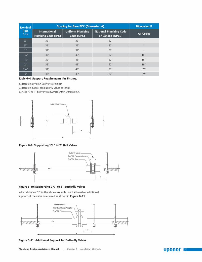
Plumbing Design Assistance Manual — Chapter 6 – Installation Methods 71
When distance “B” in the above example is not attainable, additional support of the valve is required as shown in Figure 6-11.
Figure 6-9: Supporting 1¼" to 2" Ball Valves
Figure 6-10: Supporting 2½" to 3" Butterfly Valves
Figure 6-11: Additional Support for Butterfly Valves
ProPEX Ball Valve
B
A
B
A
Butterfly Valve
ProPEX Flange Adapter
ProPEX Ring
B
A
Butterfly valve
ProPEX Flange Adapter
ProPEX Ring
Nominal Pipe Size
Spacing for Bare PEX (Dimension A) Dimension B
International
Plumbing Code (IPC)
Uniform Plumbing
Code (UPC)
National Plumbing Code
of Canada (NPCC)All Codes
1⁄2" 32" 32" 32" -
3⁄4" 32" 32" 32" -
1" 32" 32" 32" -
11⁄4" 32" 48" 32" 18"1
11⁄2" 32" 48" 32" 18"1
2" 32" 48" 32" 18"1
21⁄2" 32" 48" 32" 7"2
3" 32" 48" 32" 7"2
Table 6-4: Support Requirements for Fittings
1. Based on a ProPEX Ball Valve or similar
2. Based on ductile-iron butterfly valves or similar
3. Place ½" to 1" ball valves anywhere within Dimension A.
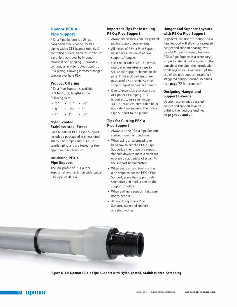
Chapter 6 – Installation Methods — uponorengineering.com72
Uponor PEX-a Pipe SupportPEX-a Pipe Support is a 23-ga. galvanized-steel channel for PEX piping with a CTS (copper tube size) controlled outside diameter. It features a profile that is over half-round, making it self-gripping. It provides continuous, uninterrupted support of PEX piping, allowing increased hanger spacing over bare PEX.
Product OfferingPEX-a Pipe Support is available in 9-foot (3m) lengths in the following sizes:
• ½"
• ¾"
• 1"
• 1¼"
• 1½"
• 2"
• 2½"
• 3"
• 3½"
Nylon-coated Stainless-steel StrapsEach bundle of PEX-a Pipe Support includes a package of stainless-steel straps. The straps carry a 300-lb. tensile rating and are tested for the appropriate applications.
Insulating PEX-a Pipe SupportThe low profile of PEX-a Pipe Support allows insulation with typical CTS pipe insulation.
Important Tips for Installing PEX-a Pipe Support
• Always follow local code for general piping support requirements.
• All pieces of PEX-a Pipe Support must have a minimum of two supports/hangers.
• Use the included 300-lb., tensile-rated, stainless-steel straps to secure the support channel to the pipe. If the included straps are misplaced, use a stainless-steel strap of equal or greater strength.
• Due to expansion characteristics of Uponor PEX piping, it is important to use a minimum 300-lb., stainless-steel cable tie or equivalent for securing the PEX-a Pipe Support to the piping.
Tips for Cutting PEX-a Pipe Support
• Always cut the PEX-a Pipe Support starting from the round side.
• When using a reciprocating or band saw to cut the PEX-a Pipe Support, either place the support flat-side down to make a clean cut or place a scrap piece of pipe into the support before cutting.
• When using a hand tool, such as a tin snips, to cut the PEX-a Pipe Support, place the support flat-side down and mark a line on the support to follow.
• When cutting a support, take care not to bend it.
• After cutting PEX-a Pipe Support, taper and smooth any sharp edges.
Hanger and Support Layouts with PEX-a Pipe SupportIn general, the use of Uponor PEX-a Pipe Support will allow for increased hanger and support spacing over bare PEX pipe. However, because PEX-a Pipe Support is a secondary-support material that is added to the outside of the pipe, the introduction of fittings or joints will interrupt the use of the pipe support, resulting in staggered hanger spacing scenarios (see page 77 for examples).
Designing Hanger and Support LayoutsUponor recommends detailed hanger and support layouts utilizing the methods outlined on pages 75 and 76.
Figure 6-12: Uponor PEX-a Pipe Support with Nylon-coated, Stainless-steel Strapping
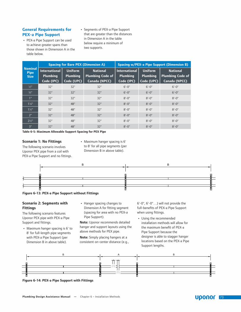
Plumbing Design Assistance Manual — Chapter 6 – Installation Methods 73
Scenario 1: No FittingsThe following scenario involves Uponor PEX pipe from a coil with PEX-a Pipe Support and no fittings.
• Maximum hanger spacing is 6' to 8' for all pipe segments (per Dimension B in above table).
Scenario 2: Segments with FittingsThe following scenario features Uponor PEX pipe with PEX-a Pipe Support and fittings.
• Maximum hanger spacing is 6' to 8' for full-length pipe segments with PEX-a Pipe Support (per Dimension B in above table).
• Hanger spacing changes to Dimension A for fitting segment (spacing for area with no PEX-a Pipe Support).
Note: Uponor recommends detailed hanger and support layouts using the above methods for PEX pipe.
Note: Simply placing hangers at a consistent on-center distance (e.g.,
6'-0", 6'-0"…) will not provide the full-benefits of PEX-a Pipe Support when using fittings.
• Using the recommended installation methods will allow for the maximum benefit of PEX-a Pipe Support because the designer is able to stagger hanger locations based on the PEX-a Pipe Support lengths.
Nominal Pipe Size
Spacing for Bare PEX (Dimension A) Spacing w/PEX-a Pipe Support (Dimension B)
International
Plumbing
Code (IPC)
Uniform
Plumbing
Code (UPC)
National
Plumbing Code of
Canada (NPCC)
International
Plumbing
Code (IPC)
Uniform
Plumbing
Code (UPC)
National
Plumbing Code of
Canada (NPCC)1⁄2" 32" 32" 32" 6'-0" 6'-0" 6'-0"
3⁄4" 32" 32" 32" 6'-0" 6'-0" 6'-0"
1" 32" 32" 32" 8'-0" 8'-0" 8'-0"
11⁄4" 32" 48" 32" 8'-0" 8'-0" 8'-0"
11⁄2" 32" 48" 32" 8'-0" 8'-0" 8'-0"
2" 32" 48" 32" 8'-0" 8'-0" 8'-0"
21⁄2" 32" 48" 32" 8'-0" 8'-0" 8'-0"
3" 32" 48" 32" 8'-0" 8'-0" 8'-0"
Table 6-5: Maximum Allowable Support Spacing for PEX Pipe
Figure 6-13: PEX-a Pipe Support without Fittings
Figure 6-14: PEX-a Pipe Support with Fittings
General Requirements for PEX-a Pipe Support
• PEX-a Pipe Support can be used to achieve greater spans than those shown in Dimension A in the table below.
• Segments of PEX-a Pipe Support that are greater than the distances in Dimension A in the table below require a minimum of two supports.
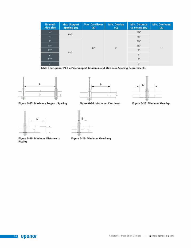
Chapter 6 – Installation Methods — uponorengineering.com74
Nominal Pipe Size
Max. Support Spacing (A)
Max .Cantilever (B)
Min. Overlap (C)
Min. Distance to Fitting (D)
Min. Overhang (E)
1⁄2"6'-0"
18" 6"
1¼"
1"
3⁄4" 1¾"
1"
8'-0"
2¼"
11⁄4" 2¾"
11⁄2" 3"
2" 4"
21⁄2" 5"
3" 6"
Table 6-6: Uponor PEX-a Pipe Support Minimum and Maximum Spacing Requirements
Figure 6-15: Maximum Support Spacing
Figure 6-18: Minimum Distance to Fitting
Figure 6-19: Minimum Overhang
Figure 6-16: Maximum Cantilever Figure 6-17: Minimum Overlap

Plumbing Design Assistance Manual — Chapter 6 – Installation Methods 75
Strapping Requirements for PEX-a Pipe SupportUponor requires PEX-a Pipe Support be strapped with a minimum 300-lb., tensile-rated, stainless-steel strap that is suitable for the application (i.e. UV, high temperature).
Note: Uponor includes required stainless-steel straps with the PEX-a Pipe Support. If the included straps are misplaced, use a stainless-steel strap of equal or greater strength.
Application Maximum Distance
ClampsGreater than 48" = 1 strap mid-span
Hangers
• Less than 48" = 2 straps equally spaced
• Greater than 48" = 3 straps (1 mid-span and 1 on each end placed 2" from end of support)
Table 6-7: Strapping Requirements for Clamps and Hangers
Figure 6-20: Strapping for Systems using Strut-type Clamps or Equivalent
Figure 6-21: Strapping for Systems using Clevis or Loop-type Hangers or Equivalent
Strap within 1" of hangerStrap at mid-spanClevis or loop hangerPEX-a Pipe Support
Strap at mid-spanStrut clampPEX-a Pipe Support

Chapter 6 – Installation Methods — uponorengineering.com76
Expansion and Contraction Control with PEX-a Pipe Support
When properly installed, Uponor PEX-a Pipe Support can reduce linear expansion and contraction by up to 93 percent when compared to bare-PEX pipe. For more information, refer to Table 5-15 on Page 61.
Refer to the following requirements.
• 300-lb., tensile-rated, stainless-steel straps (included)
• Fixed anchor points installed every 65 ft. for domestic hot-water applications (ΔT>40˚F)
• Fixed anchor points installed every 150 ft. for domestic cold-water applications (ΔT>40˚F)
Figure 6-23: PEX-a Pipe Support with Stainless-steel Strapping
ASTM E84 Requirements for PEX-a Pipe SupportUponor PEX-a Pipe Support has been tested and approved for use in ASTM E84 applications. To meet the requirements, PEX-a Pipe Support must be installed per the following requirements:
• Pipe or fittings without PEX-a Pipe Support shall be covered with a minimum ½" thick insulation.
• There is no minimum segment length of PEX-a Pipe Support.
When installed per the above requirements, there are no spacing limitations between parallel piping runs.
Note: The above requirements also apply to PEX-a Pipe Support installed in a vertical position for ASTM E84 applications.
Note: Exposed sections of ½" and ¾ Uponor PEX pipe can be installed un-insulated if the pipe runs are separated by a minimum of 18".
Figure 6-22: PEX-a Pipe Support Installations in ASTM E84 Applications
Rated insulation
ProPEX fitting
Uponor PEX pipe
Uponor PEX-a Pipe Support
Exposed section must be insulated
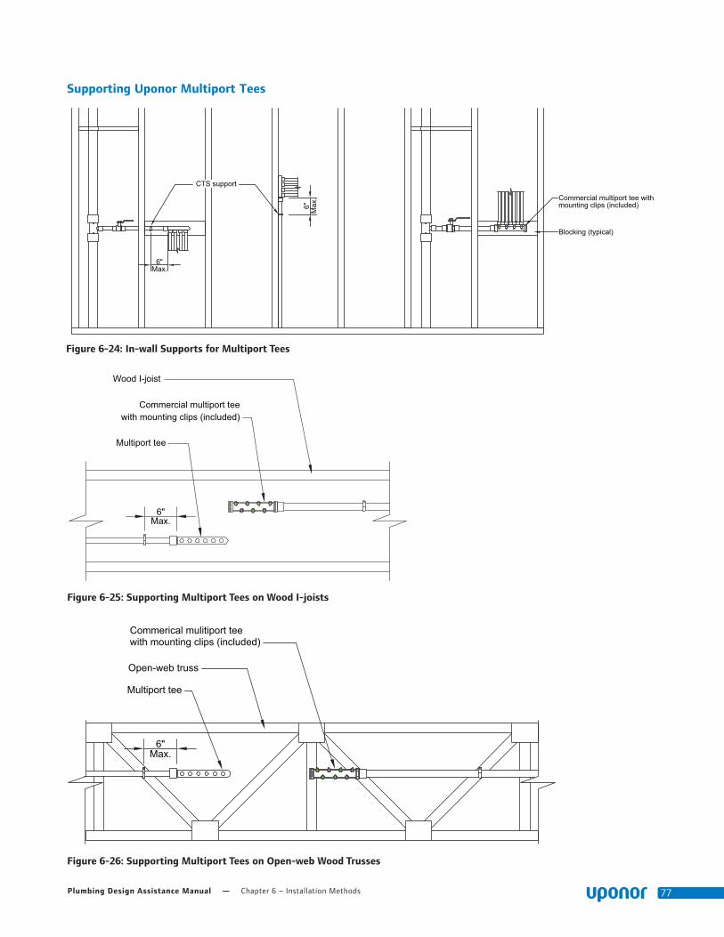
Plumbing Design Assistance Manual — Chapter 6 – Installation Methods 77
Figure 6-25: Supporting Multiport Tees on Wood I-joists
Figure 6-26: Supporting Multiport Tees on Open-web Wood Trusses
Figure 6-24: In-wall Supports for Multiport Tees
Wood I-joist
Commercial multiport teewith mounting clips (included)
Multiport tee
6"Max.
Commerical mulitiport teewith mounting clips (included)
6"Max.
Open-web truss
Multiport tee
CTS support
Commercial multiport tee withmounting clips (included)
Blocking (typical)
6"Max.
6" Max
.
Supporting Uponor Multiport Tees

Chapter 6 – Installation Methods — uponorengineering.com78
Figure 6-27: Supporting Multiport Tees in Suspended Applications
Figure 6-28: Supporting Multiport Tees on Drywall Grid
6"Max.
Multiport tee
CTS hanger
6"Max.
Grid hanger wire
CTS clamp
Drywall grid
Drywall cross tee

Plumbing Design Assistance Manual — Chapter 6 – Installation Methods 79
Vertical Support RequirementsVertical runs of pipe can be divided into two categories: in wall and risers.
In-wall piping is typically smaller in diameter (<1"), and does not pass through multiple stories like a riser. It is most often the dedicated supply piping to the fixture.
Riser piping is typically larger in diameter (>1") and passes through multiple stories, often requiring fire-penetration sealants.
Note: The two categories above are not mutually exclusive. Use best judgement when determining which supports are necessary.
Figure 6-29: In-wall versus Riser Piping
Nominal Pipe Size
International Plumbing Code
(IPC)
Uniform Plumbing Code
(UPC)
National Plumbing Code
of Canada
Ver
tica
l In w
all
All Pipe Sizes
5'-0" (1.5m) 5'-0" (1.5m) 5'-0" (1.5m)
Ris
ers
All Pipe Sizes
Base of each floor; provide mid-story
guide
Base of each floor; provide mid-story
guide
Supported at the base and floor levels of alternate stories
Table 6-8: Vertical Support Requirements for PEX Pipe
5'-0
" max
.5'
-0" m
ax.
Uponor PEXin-wall piping
Floor penetration
Mid-story guide
Uponor PEX riser
Riser clamp
Floor penetration
Stud
Support bracket
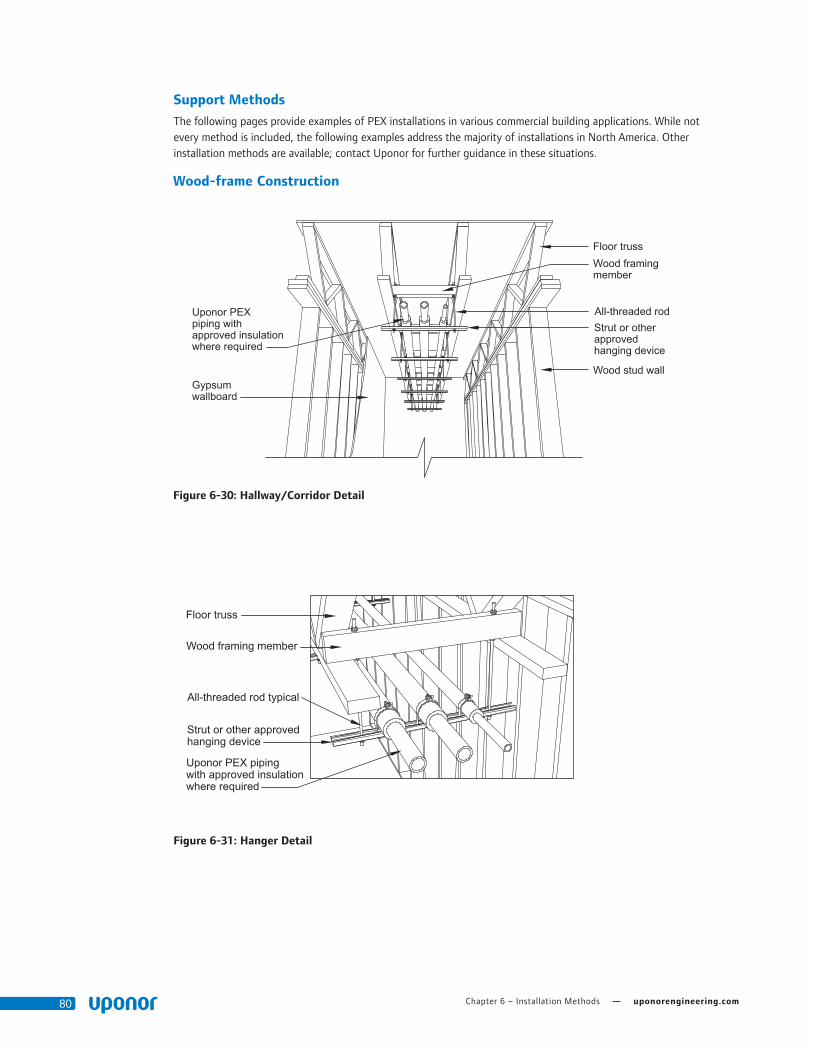
Chapter 6 – Installation Methods — uponorengineering.com80
Support Methods
The following pages provide examples of PEX installations in various commercial building applications. While not every method is included, the following examples address the majority of installations in North America. Other installation methods are available; contact Uponor for further guidance in these situations.
Wood-frame Construction
Figure 6-30: Hallway/Corridor Detail
Uponor PEXpiping withapproved insulationwhere required
Gypsumwallboard
Floor trussWood framingmember
All-threaded rodStrut or otherapprovedhanging device
Wood stud wall
Uponor PEX piping with approved insulationwhere required
Floor truss
Wood framing member
All-threaded rod typical
Strut or other approvedhanging device
Figure 6-31: Hanger Detail
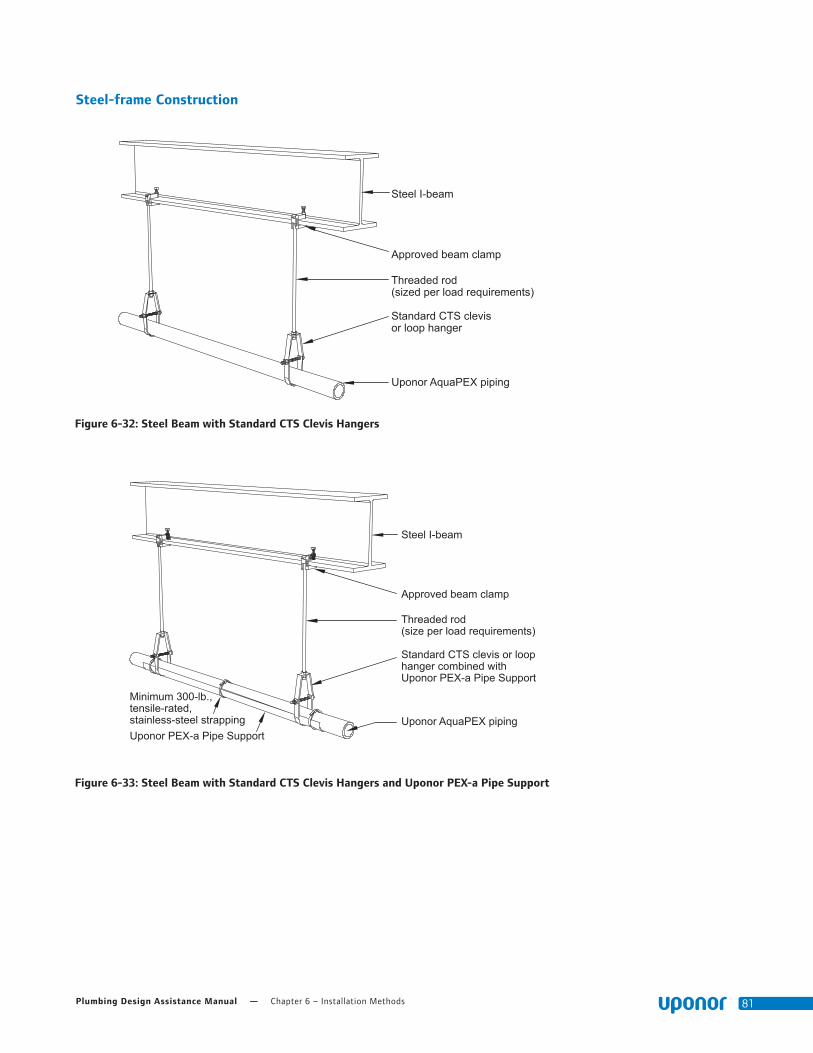
Plumbing Design Assistance Manual — Chapter 6 – Installation Methods 81
Steel-frame Construction
Figure 6-32: Steel Beam with Standard CTS Clevis Hangers
Figure 6-33: Steel Beam with Standard CTS Clevis Hangers and Uponor PEX-a Pipe Support
Steel I-beam
Approved beam clamp
Threaded rod(sized per load requirements)
Standard CTS clevisor loop hanger
Uponor AquaPEX piping
Steel I-beam
Approved beam clamp
Minimum 300-lb.,tensile-rated,stainless-steel strappingUponor PEX-a Pipe Support
Threaded rod(size per load requirements)
Standard CTS clevis or loophanger combined withUponor PEX-a Pipe Support
Uponor AquaPEX piping

Chapter 6 – Installation Methods — uponorengineering.com82
Steel joist
Beam clamp
All-threaded rod
Minimum 300-lb., tensile-rated,stainless-steel strapping
Strut clamp
Uponor AquaPEX piping
Uponor PEX-a Pipe Support
Steel strut or other approved hanging device
Figure 6-34: Uponor PEX Suspended from Steel Joists with Strut and Uponor PEX-a Pipe Support
Figure 6-35: Uponor PEX Supported by Steel Joists and PEX-a Pipe Support
Steel joist
Uponor AquaPEXpiping
Uponor PEX-a Pipe Support
Minimum 300-lb.,tensile-rated,stainless-steel strapping

Plumbing Design Assistance Manual — Chapter 6 – Installation Methods 83
Expansion-compensating DevicesAs a generally accepted practice, an expansion-controlling device with fixed anchor points or a continuous run of PEX-a Pipe Support with fixed anchor points is installed every 65 ft. of straight-length piping in a domestic hot-water system. Always install the device at the mid-point of two fixed points (see Figure 6-36).
Two hole open short angle
Steel strut
All-threaded rod
Two hole open short angle
Strut clamp
Uponor PEX-a pipe
Steel strut or other approved device
Figure 6-36: Fixed Anchor Point
Figure 6-37: Expansion Arm
Figure 6-38: Expansion Loop
Fixed Anchor PointsTo account for expansion, use fixed anchor points to restrict piping movement. Ensure fixed anchor points are constructed with materials that will provide rigidity to the support system and use a pipe clamp that will restrain the specific piping material.
When installing strut-type applications, Uponor recommends using rubber-lined strut clamps to aid in the restriction of movement.
Expansion ArmThe flexible arm should be long enough to prevent damage; place support clamps far enough from the wall to allow for longitudinal thermal expansion.
For a list of calculated flexible arm lengths, refer to Appendix E.
Expansion LoopThe same applies for an expansion loop. However, the arm length (LB) must be divided into three sections.
For a list of calculated expansion
loop legs, refer to Appendix E.
Fixed anchor point
Fixed anchor point
L ∆L
LB
Fixed anchor point
∆L/2L
∆L/2
L2 L2
L1
Fixed anchor point
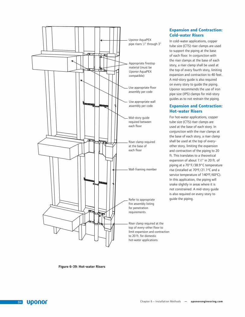
Chapter 6 – Installation Methods — uponorengineering.com84
Expansion and Contraction: Cold-water RisersIn cold-water applications, copper tube size (CTS) riser clamps are used to support the piping at the base of each floor. In conjunction with the riser clamps at the base of each story, a riser clamp shall be used at the top of every fourth story, limiting expansion and contraction to 40 feet. A mid-story guide is also required on every story to guide the piping. Uponor recommends the use of iron pipe size (IPS) clamps for mid-story guides as to not restrain the piping.
Expansion and Contraction: Hot-water RisersFor hot-water applications, copper tube size (CTS) riser clamps are used at the base of each story. In conjunction with the riser clamps at the base of each story, a riser clamp shall be used at the top of every-other story, limiting the expansion and contraction of the piping to 20 ft. This translates to a theoretical expansion of about 11⁄2" in 20 ft. of piping at a 70°F/38.9°C temperature rise (installed at 70ºF/21.1ºC and a service temperature of 140ºF/60ºC). In this application, the piping will snake slightly in areas where it is not constrained. A mid-story guide is also required on every story to guide the piping.
Figure 6-39: Hot-water Risers
Use appropriate floorassembly per code
Uponor AquaPEX pipe risers 1/2" through 3"
Appropriate firestop material (must be Uponor AquaPEX compatible)
Mid-story guide required between each floor
Riser clamp requiredat the base of each floor
Wall-framing member
Refer to appropriatefire assembly listingfor penetration requirements
Riser clamp required at the top of every-other floor to limit expansion and contraction to 20 ft. for domestic hot-water applications
Use appropriate wallassembly per code

Plumbing Design Assistance Manual — Chapter 6 – Installation Methods 85
Public-use Fixtures
Water hammer is probably the most significant concern when piping for public-use fixtures.
In typical installations with metallic piping where back-to-back restrooms are separated by a mechanical chase, the supply header is usually kept at roughly the same height as the fixture supply. This creates sharp, abrupt paths for the water, resulting in pressure surges (water hammer) when a fast-actuating valve closes. To compensate, most local codes require water hammer arrestors.
The flexibility of Uponor AquaPEX piping combined with its ability to withstand high surge pressures makes it the perfect product for supplying public-use fixtures. PEX has an approximate modulus of elasticity of 91,350 psi, compared to copper’s 16,000,000 psi. Refer
to Chapter 5 for more information about expansion and contraction.
Because Uponor requires a minimum distance between ProPEX fittings (see Table 2-2), take care when creating a fixture header. In typical installations using Uponor AquaPEX, the PEX header is elevated to allow for adequate spacing between ProPEX tees and to also offer ample room for AquaPEX pipe drops to the fixture (see Figure 6-41).
Pipe LabelsIf pipe labels are required to be affixed to Uponor AquaPEX pipe, Uponor approves the use of permanent, flexible, vinyl stickers with pressure-sensitive acrylic. Consult local code for proper placement and requirements regarding pipe labelling.
Water hammer arrestor where required by code (exact locations vary by manufacturer)
Isolation ball valve (typical)
Bend support(½" to ¾" typical)
Vent pipe
Wastepipe
Urinal carrier behind
Copper stub
Uponor AquaPEX pipeheader (size varies)
Stud wall assembly
Uponor ProPEX EP Tee
Support
Uponor AquaPEX pipe supply (size varies)
Copper carrier bracket
Water closet carrier
Commercial Flush Bank Detail
Figure 6-41: Fixture Bank Elevation View
Figure 6-40: Fixture Bank Section View
Wall Assembly
Uponor AquaPEX pipeheader (size varies)
Support
Uponor AquaPEX pipesupply (size varies)
Vent pipe
Uponor ProPEX Lead-free (LF)Brass Sweat Adapter
Copper stub
Copper carrier bracket
Water closet carrier
Chapter 6 – Installation Methods — uponorengineering.com86
Under-slab/Below- grade Installation
An alternative method to overhead piping is under-slab or below-grade piping. In this installation, the pipe is laid in a trench and routed to the desired locations. The piping system is pressurized (usually 20 psi above working pressure) and buried. Because PEX piping is available in long, continuous lengths, it is an ideal material for running below grade without fittings. (See the Water Service section for proper trench preparation.)
Under-slab/ Below-grade FittingsUponor EP and LF brass fittings are all approved for use in direct-burial applications.
Uponor's LF brass is approved for direct burial in soil per NSF/ANSI Standard 14 testing which established minimum performance criteria for dezincification resistance (DZR) and stress-corrosion cracking (SCC) resistance for PEX fittings intended for potable water.
Installation RecommendationsUponor AquaPEX piping for hot- and cold-water distribution is approved for installation directly within or below concrete slabs where soil termiticide/pesticide treatment is required. This is especially useful in slab-on-grade construction. See page 92 for information about termiticides.
Pre-insulated Uponor AquaPEX PipingPre-insulated Uponor AquaPEX piping is approved for use in direct-burial applications. However, due to the static load exerted by the soil, Uponor recommends the use of Pre-insulated AquaPEX with a minimum 1"-thick insulation.
Piping passing through a concrete slab must be protected with 0.025" (0.064mm) thick protective material such as HDPE wrapping, closed-cell
pipe insulation, PVC elbows and sleeves or equivalent that allow expansion and contraction of the piping. Ensure proper placement where piping exits the slab. These products are described as slab-penetration protection devices.
Pre-sleeved Uponor AquaPEX PipingWhen using pre-sleeved Uponor AquaPEX piping or a protection sleeve, an annular gap between these protection devices and the PEX piping will exist. In such installations, fill the annular gap between the protection device and the PEX piping at the exposed ends to help prevent pathways for pests and the mistaken application of harmful chemicals into the space between the PEX piping and the protection device. Use only sealants that are compatible with PEX piping.
Note: The following products are appropriate for use when sealing PEX piping and slab-penetration protection devices:
• Latex caulk
• Latex foam
• Silicone sealant
• Polyurethane expanding foam
Note: Misapplication of these products could result in pooling or puddling of the products around the PEX piping, which is prohibited.
Caution:
• If applying termiticides/pesticides while the installed PEX piping still has exposed open ends that are not yet connected to plumbing fixtures, cap, plug or close the ends of the piping to prevent these chemicals from entering the piping.
• Do not allow organic (petroleum-based) chemicals, petroleum distillates, termiticides or pesticides to come into direct contact with PEX piping.
• Fill the annular gap between PEX piping and slab-penetration protection devices (sleeving or PVC bend guides) at the ends of the piping to help prevent pathways for pests and the mistaken application of harmful chemicals into the space between the PEX piping and the protection device. Use only sealants that are compatible with PEX piping.
• When PEX piping is continuously sleeved below or above a slab (such as when using Pre-sleeved Uponor AquaPEX piping), never fill the space between the PEX piping and the sleeving with any liquid chemical, including pesticides or termiticides. Prevent pooling or puddling of these liquids around PEX piping.
• When it is necessary to re-treat soil near PEX piping, prevent the puddling or pooling of the termiticide/pesticide.
Water Service
Requirements
Uponor AquaPEX piping and associated fittings meet the requirements of American Water Works Association (AWWA) C904, Cross-linked Polyethylene (PEX) Pressure Pipe, ½" (12mm) through 3" (76mm) for Water Service.
Only use SDR9 compression fittings listed in compliance with AWWA C800 as referenced in AWWA C904 in water service applications when transferring from PEX to a corporation or curb stop. Be sure to use insert stiffeners when assembling a compression fitting with PEX. Commonly available SDR9 compression fitting manufacturers include:
• Ford Meter Box Company, Inc.®
• Mueller Company®
• A.Y. McDonald Mfg. Co.®
• Philmac®

Plumbing Design Assistance Manual — Chapter 6 – Installation Methods 87
Header
Masonry wall
Steel strut with strut clamps
Ball valve
Uponor AquaPEXpiping from below
Closed-cell pipeinsulation where required
PVC SleeveFinished concrete floor
Figure 6-42: Mechanical Room Transition (Below-grade Piping)
Mechanical chase
Concrete slab
Wall assembly
Steel strut
PVC bend support
Uponor AquaPEX below grade
Strut clamps
PVC sleeve at concrete penetration
Figure 6-44: Wet-wall Chase Transition (Below-grade Piping) Figure 6-43: Uponor AquaPEX Below Grade
Trace WireUponor recommends the use of trace wire to facilitate the detection of underground pipe systems. Trace wire should be 14-gauge minimum solid copper with thermoplastic insulation suitable for direct burial. Refer to local code for further requirements.
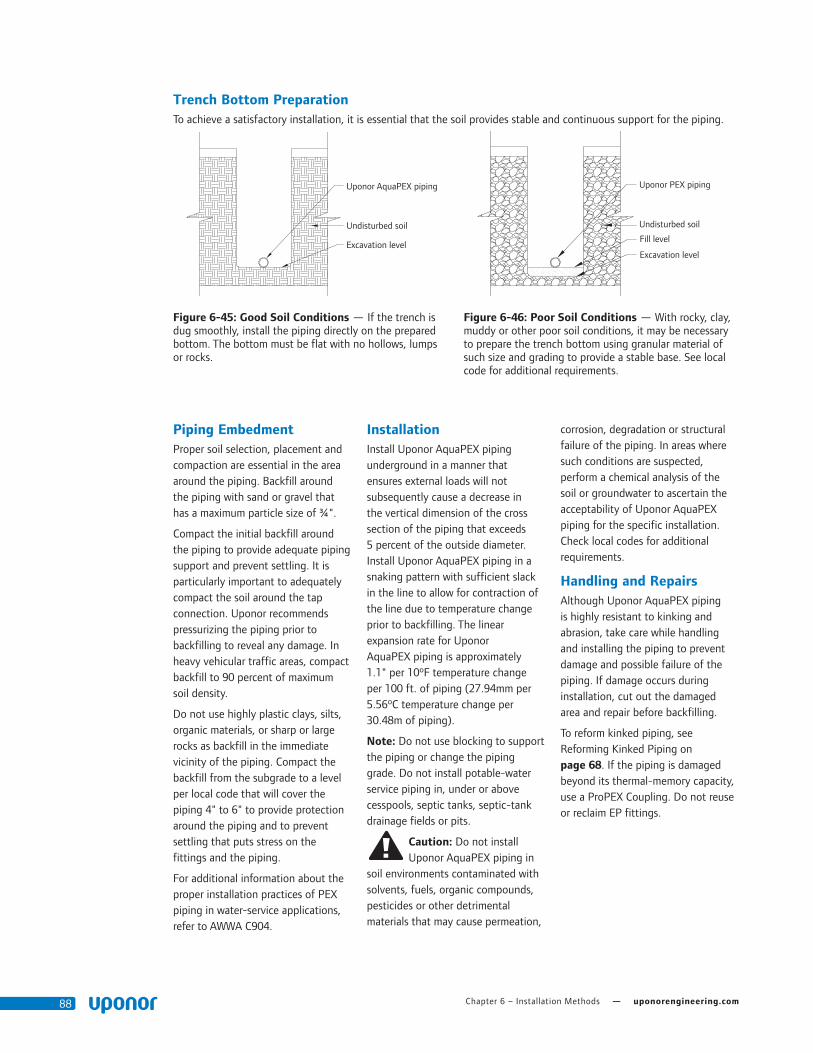
Chapter 6 – Installation Methods — uponorengineering.com88
Piping EmbedmentProper soil selection, placement and compaction are essential in the area around the piping. Backfill around the piping with sand or gravel that has a maximum particle size of ¾".
Compact the initial backfill around the piping to provide adequate piping support and prevent settling. It is particularly important to adequately compact the soil around the tap connection. Uponor recommends pressurizing the piping prior to backfilling to reveal any damage. In heavy vehicular traffic areas, compact backfill to 90 percent of maximum soil density.
Do not use highly plastic clays, silts, organic materials, or sharp or large rocks as backfill in the immediate vicinity of the piping. Compact the backfill from the subgrade to a level per local code that will cover the piping 4" to 6" to provide protection around the piping and to prevent settling that puts stress on the fittings and the piping.
For additional information about the proper installation practices of PEX piping in water-service applications, refer to AWWA C904.
InstallationInstall Uponor AquaPEX piping underground in a manner that ensures external loads will not subsequently cause a decrease in the vertical dimension of the cross section of the piping that exceeds 5 percent of the outside diameter. Install Uponor AquaPEX piping in a snaking pattern with sufficient slack in the line to allow for contraction of the line due to temperature change prior to backfilling. The linear expansion rate for Uponor AquaPEX piping is approximately 1.1" per 10ºF temperature change per 100 ft. of piping (27.94mm per 5.56ºC temperature change per 30.48m of piping).
Note: Do not use blocking to support the piping or change the piping grade. Do not install potable-water service piping in, under or above cesspools, septic tanks, septic-tank drainage fields or pits.
Caution: Do not install Uponor AquaPEX piping in
soil environments contaminated with solvents, fuels, organic compounds, pesticides or other detrimental materials that may cause permeation,
corrosion, degradation or structural failure of the piping. In areas where such conditions are suspected, perform a chemical analysis of the soil or groundwater to ascertain the acceptability of Uponor AquaPEX piping for the specific installation. Check local codes for additional requirements.
Handling and RepairsAlthough Uponor AquaPEX piping is highly resistant to kinking and abrasion, take care while handling and installing the piping to prevent damage and possible failure of the piping. If damage occurs during installation, cut out the damaged area and repair before backfilling.
To reform kinked piping, see Reforming Kinked Piping on page 68. If the piping is damaged beyond its thermal-memory capacity, use a ProPEX Coupling. Do not reuse or reclaim EP fittings.
Uponor AquaPEX piping
Undisturbed soil
Excavation level
Uponor PEX piping
Undisturbed soil
Fill level
Excavation level
Trench Bottom PreparationTo achieve a satisfactory installation, it is essential that the soil provides stable and continuous support for the piping.
Figure 6-45: Good Soil Conditions — If the trench is dug smoothly, install the piping directly on the prepared bottom. The bottom must be flat with no hollows, lumps or rocks.
Figure 6-46: Poor Soil Conditions — With rocky, clay, muddy or other poor soil conditions, it may be necessary to prepare the trench bottom using granular material of such size and grading to provide a stable base. See local code for additional requirements.

Plumbing Design Assistance Manual — Chapter 6 – Installation Methods 89
Horizontal Directional Drilling (HDD)Horizontal directional drilling is used when trenching or excavation is not practical. A surface-launched drilling rig provides a steerable, trenchless method of installing underground pipes along a shallow arc bore path, resulting in minimal impact to surrounding areas. It is suitable for a variety of soil conditions.
HDD is further categorized into the following types:
• Mini-HDD
• Distances less than 600 ft.
• Depths up to 15 ft.
• Pipe diameters up to 12"
• Equipment pullback capability of up to 20,000 lbs. and torque less than 950 ft-lbs.
• Maxi-HDD
• Distances greater than 600 ft.
• Depths up to 200 ft.
• Pipe diameters up to 48"
• Equipment pullback capability of up to 100,000 lbs. and torque up to 80,000 ft-lbs.
Criteria for Uponor PEX Piping in HDD Applications
• Use Uponor PEX only as the follow pipe.
• Take precautionary steps to ensure piping does not come in contact with sharp objects.
• Do not exceed minimum bend radius of 6 times the O.D. of the piping
• Pressure test installed piping after installation to ensure the integrity of the piping has not been compromised.
Reference Plastics Pipe Institute’s Technical Report (TR) 46 Guidelines for Use of Mini-Horizontal Directional Drilling for Placement of High Density Polyethylene Pipe for HDD applications using Uponor PEX piping.
Joining Methods and FittingsUse ProPEX or approved compression fittings to connect piping to itself or to the corporation and curb stops. Approved manufactures are Ford Meter Box Company, Mueller Company, A.Y. McDonald Mfg. Co. and Philmac.
When using compression fittings with Uponor AquaPEX piping, a plastic or stainless-steel insert stiffener is required on the inside of the piping at the connection.
For applications requiring direct burial, use Uponor ProPEX EP or LF brass fittings for large-dimension Uponor AquaPEX piping up to 3".
H-20 LoadsWhen installing Uponor AquaPEX under a roadway, follow the same procedures as previously indicated with the following exception: Ensure the top of the piping is 16" below the bottom of the roadbed material as specified. You can also use a suitable steel or structural conduit to sleeve the Uponor AquaPEX pipe.
Figure 6-47: Traffic Loads
H-20 load
Deepest point of road bed 0 2083 pounds p.s.f.
10" native soil
6" sand (min.)
Service pipe
4" sandbed
BicyclesPedestrians
SDR9 Uponor PEX 12-hour Pull
Nominal Pipe Size
Tensile Yield Design
(safety) Factor
Allowable Tensile Load
at 73°F/22.8°C - lbs (N)
1⁄2" 0.4 128 (569)
3⁄4" 0.4 248 (1,103)
1" 0.4 411 (1,828)
11⁄4" 0.4 615 (2,735)
11⁄2" 0.4 859 (3,821)
2" 0.4 1,465 (6,516)
21⁄2" 0.4 2,239 (9,960)
3" 0.4 3,169 (14,096)
Table 6-9: Safe Pull Force
Note: The method set forth in ASTM F1804 determines the allowable tensile load.

Chapter 6 – Installation Methods — uponorengineering.com90
Water System DisinfectionUponor recommends flushing an AquaPEX plumbing system with clean, potable water. When system disinfection is required, disinfect the piping in accordance with AWWA C651-86, Standard for Disinfecting Water Mains, or local codes.
Important: To prevent reduced service life of system components, do not allow disinfection solutions to remain in the system longer than 24 hours. Flush the system with potable water after disinfection. Use a chlorine solution of 50 parts per million (ppm) for 24 hours or 200 ppm for three hours for disinfection.
Pressure-testing ProceduresIt is important to properly pressure test an Uponor Plumbing System in accordance with local code. If testing with air, it is important the system pressure not exceed 120 psi.
The following procedure is acceptable for testing with air, water or a mixture of both for Uponor AquaPEX piping and ProPEX fittings or hybrid systems combined with metallic piping.
Important: When pressure testing hybrid systems
(i.e., those that include both thermoplastic piping materials, such as CPVC or PP-R, and Uponor AquaPEX and ProPEX fittings), isolate the Uponor system from the other thermoplastic materials in the
system before following the recommended procedure.
Also, consult the appropriate pipe manufacturer’s installation recommendations when testing systems comprised of other thermoplastic materials.
The intent of pressure testing a domestic-water system is to meet local code requirements while ensuring the system is free from leaks. Pressure testing is not a substitute for the correct installation of an Uponor AquaPEX and ProPEX Plumbing System. It is essential the Uponor system is accurately sized, supported and protected while also accounting for thermal movement during installation.
Importance of Conditioning PEX-a PipeUponor recommends conditioning the system at 1.5 times the test pressure, or 120 psi. The following conditioning procedure is unique to PEX-a pipe due to the high degree of crosslinking and associated thermal and elastic properties of the pipe.
When pressure is applied against the inner wall of PEX-a pipe, the internal diameter (ID) of the pipe will slightly increase, causing the pressure to drop while the system equalizes. After a period of 30 minutes, the PEX piping will be sufficiently conditioned to start the pressure test.
Conditioning and Sustained Pressure Testing Procedure1. Visually confirm all connections
are properly made per Uponor installation guidelines.
2. Ensure all components, fixtures and equipment not rated for the test pressure are isolated from the test system.
3. Ensure all other thermoplastic piping materials are isolated from the test system.
4. Fill the system with potable water, air or a mixture of both.
5. Condition the system to 1.5 times the required test pressure for 30 minutes. This will require constant pumping or cycling the valve and compressor to maintain a pressure of 1.5 times the test pressure. If cycling the valve and compressor, apply additional pressure once the psi has dropped 10 lbs.
6. After conditioning the system for 30 minutes, quickly relieve excess pressure by opening the valve. Close the valve when the system has reached the desired test pressure.
Note: Uponor recommends a test pressure of 80 psi (unless local code dictates higher pressures).
7. Once the valve is closed, confirm a slight rise in pressure (3 to 6 psi). This increase will occur as the pipe’s internal diameter (ID) is shrinking from its conditioned state to equalize at the lower pressure.
8. Visually check for leakage and monitor the pressure for the duration specified by local code. (A typical pressure test can range from 2 to 24 hours.)
9. If there is no reduction in pressure, the system is presumed to be free from leaks.
60
70
80
90
100
110
120
130
140
0 10 20 30 40 50 60 70 80 90 100 110 120
Pre
ssur
e (p
si)
Time (min.)
Pressure Testing Graph System Pressure
Figure 6-48: Pressure Testing Graph
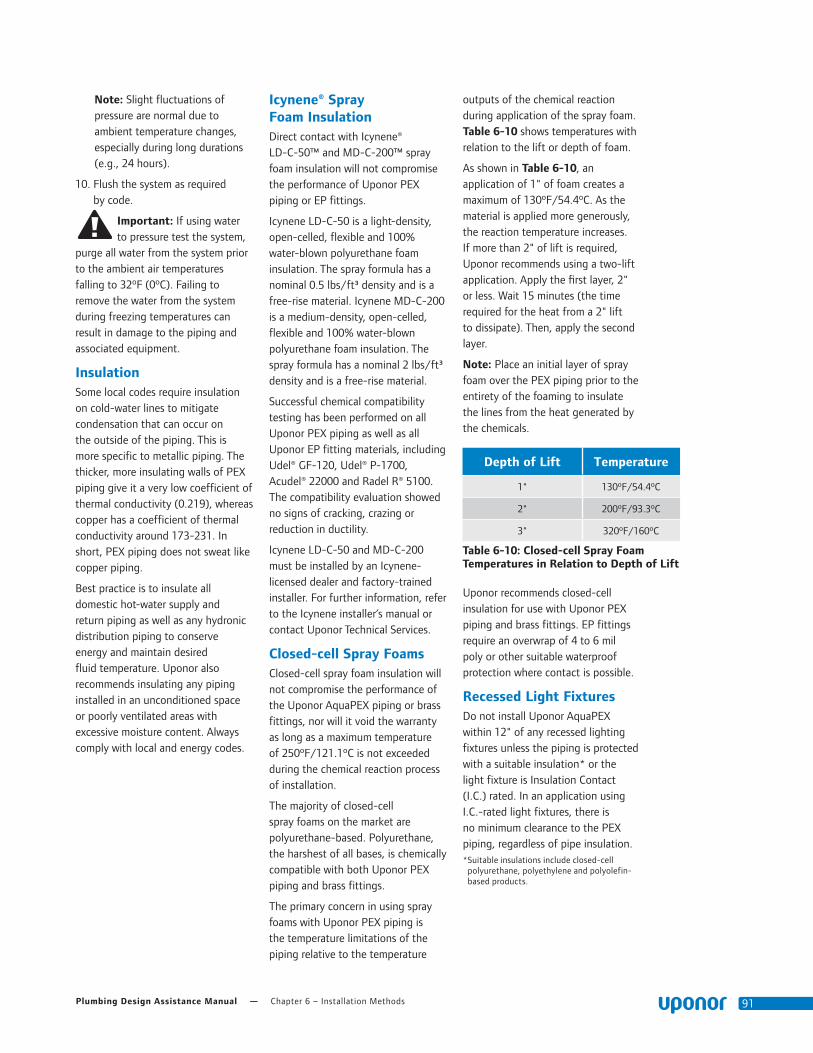
Plumbing Design Assistance Manual — Chapter 6 – Installation Methods 91
Note: Slight fluctuations of pressure are normal due to ambient temperature changes, especially during long durations (e.g., 24 hours).
10. Flush the system as required by code.
Important: If using water to pressure test the system,
purge all water from the system prior to the ambient air temperatures falling to 32ºF (0ºC). Failing to remove the water from the system during freezing temperatures can result in damage to the piping and associated equipment.
InsulationSome local codes require insulation on cold-water lines to mitigate condensation that can occur on the outside of the piping. This is more specific to metallic piping. The thicker, more insulating walls of PEX piping give it a very low coefficient of thermal conductivity (0.219), whereas copper has a coefficient of thermal conductivity around 173-231. In short, PEX piping does not sweat like copper piping.
Best practice is to insulate all domestic hot-water supply and return piping as well as any hydronic distribution piping to conserve energy and maintain desired fluid temperature. Uponor also recommends insulating any piping installed in an unconditioned space or poorly ventilated areas with excessive moisture content. Always comply with local and energy codes.
Icynene® Spray Foam InsulationDirect contact with Icynene® LD-C-50™ and MD-C-200™ spray foam insulation will not compromise the performance of Uponor PEX piping or EP fittings.
Icynene LD-C-50 is a light-density, open-celled, flexible and 100% water-blown polyurethane foam insulation. The spray formula has a nominal 0.5 lbs/ft³ density and is a free-rise material. Icynene MD-C-200 is a medium-density, open-celled, flexible and 100% water-blown polyurethane foam insulation. The spray formula has a nominal 2 lbs/ft³ density and is a free-rise material.
Successful chemical compatibility testing has been performed on all Uponor PEX piping as well as all Uponor EP fitting materials, including Udel® GF-120, Udel® P-1700, Acudel® 22000 and Radel R® 5100. The compatibility evaluation showed no signs of cracking, crazing or reduction in ductility.
Icynene LD-C-50 and MD-C-200 must be installed by an Icynene-licensed dealer and factory-trained installer. For further information, refer to the Icynene installer’s manual or contact Uponor Technical Services.
Closed-cell Spray FoamsClosed-cell spray foam insulation will not compromise the performance of the Uponor AquaPEX piping or brass fittings, nor will it void the warranty as long as a maximum temperature of 250ºF/121.1ºC is not exceeded during the chemical reaction process of installation.
The majority of closed-cell spray foams on the market are polyurethane-based. Polyurethane, the harshest of all bases, is chemically compatible with both Uponor PEX piping and brass fittings.
The primary concern in using spray foams with Uponor PEX piping is the temperature limitations of the piping relative to the temperature
outputs of the chemical reaction during application of the spray foam. Table 6-10 shows temperatures with relation to the lift or depth of foam.
As shown in Table 6-10, an application of 1" of foam creates a maximum of 130ºF/54.4ºC. As the material is applied more generously, the reaction temperature increases. If more than 2" of lift is required, Uponor recommends using a two-lift application. Apply the first layer, 2" or less. Wait 15 minutes (the time required for the heat from a 2" lift to dissipate). Then, apply the second layer.
Note: Place an initial layer of spray foam over the PEX piping prior to the entirety of the foaming to insulate the lines from the heat generated by the chemicals.
Uponor recommends closed-cell insulation for use with Uponor PEX piping and brass fittings. EP fittings require an overwrap of 4 to 6 mil poly or other suitable waterproof protection where contact is possible.
Recessed Light FixturesDo not install Uponor AquaPEX within 12" of any recessed lighting fixtures unless the piping is protected with a suitable insulation* or the light fixture is Insulation Contact (I.C.) rated. In an application using I.C.-rated light fixtures, there is no minimum clearance to the PEX piping, regardless of pipe insulation. * Suitable insulations include closed-cell
polyurethane, polyethylene and polyolefin- based products.
Depth of Lift Temperature
1" 130ºF/54.4ºC
2" 200ºF/93.3ºC
3" 320ºF/160ºC
Table 6-10: Closed-cell Spray Foam Temperatures in Relation to Depth of Lift

Chapter 6 – Installation Methods — uponorengineering.com92
Painting Uponor AquaPEXIt is acceptable to use latex and acrylic-based paint, such as 100 percent acrylic exterior latex house paint, with Uponor AquaPEX. These products will not harm the molecular structure or integrity of the PEX piping.
Termiticides/Pesticides Liquid termiticides/pesticides are often applied to treat the soil below the concrete slabs of slab-on-grade structures. The treatment creates a barrier to prevent termites and pests from infiltrating the floor of the structure. PEX piping for plumbing applications is often installed within slabs or below slabs (in trenches in the soil) below the soil that is treated. Liquid termiticides/pesticides use a liquid solvent to carry the active ingredients. These solvents can be categorized as one of two types: organic solvent-based (also known as petroleum solvent-based) and water-based (water solvent-based).
The type of solvent used in a termiticide/pesticide will affect its ability to permeate through various materials. Organic-based termiticides/pesticides have largely disappeared from the North American marketplace for this application, and the majority of products available today are water-based. Water-based products are generally safer for the environment and pose less risk of infiltration into PEX piping.
Available data indicates the solvents used in liquid termiticides/pesticides will soak into the ground and/or evaporate before they can pass through the wall of polyethylene piping. The data also indicates these solvents are prevented from passing through the wall of polyethylene piping because of the large size of the water- or organic-solvent molecules, relative to the size of the molecules in the piping itself. Once liquid solvents have dissipated or
evaporated, the solids that remain behind cannot permeate through the walls of polyethylene or PEX piping because of the molecular size.
Additional research shows that water-based termiticides/pesticides are of sufficiently large molecular size to completely prevent permeation through polyethylene and PEX piping. Instances of water-based termiticides/pesticides permeating through polyethylene or PEX piping are not known. Pesticides have not been found to be corrosive or have polymer degradation.
Although all research data and anecdotal evidence strongly suggest there are no permeation issues with water-based termiticides/pesticides and PEX, take extra caution to ensure safe installation of PEX piping and to prevent misapplication or pooling/puddling of the liquid termiticides/pesticides around PEX piping.
Supporting ResearchA study done in 2001 in Australia, titled “Investigating the Possible Permeation of Organic Chemicals Commonly Used in Termiticide Barrier Treatments through Polyethylene Water Pipes,” indicated that “migration of pesticide constituents and their associated solvents, through the polyethylene pipe, did not occur, indicating that the concentration of solvents (even in the saturated soil) was not high enough to cause permeation of the solvents through the polyethylene pipe wall (within the 16-week period of study).” The study also stated “this indicates that the concentration of these constituents in the soil in contact with the pipes was not high enough to develop a positive diffusion pressure and cause the constituents to be detected in the water.” The study was conducted using organic solvent-based pesticides, which are known to be more aggressive than water-based pesticides. Therefore, the results are valid for organic
solvent-based pesticides and water-based pesticides.
Research conducted by Dr. Michael R. Hoffman of the California Institute of Technology (2005) indicates that the ability of a chemical compound to permeate a material is correlated directly with the octanol-water partition coefficients of the individual organic chemicals. The octanol-water partition coefficient is a relative measure of the hydrophobic nature of the organic compounds. In spite of a measurable tendency to partition into plastic material, the ability of these compounds is retarded substantially given the low measured diffusion coefficients for selected chemicals. For example, a PEX piping wall thickness of 5mm and a typical diffusion coefficient for organic compound migration of 1.0 x 10⁻¹² cm2/s, the time to permeate through the walls, would be 2.5 x 1,011 seconds or approximately 8,000 years. If the wall thickness was reduced to 2mm, then the time to permeate completely through the pipe wall would be reduced to 1,300 years.
Note: Crosslinked polyethylene (PEX) piping is assumed to behave similarly to polyethylene water piping.

Plumbing Design Assistance Manual — Appendix A – Fluid Properties 93
Appendix A
Fluid Properties
100% Water
Temperature ºF (ºC)
Density (lbm/ft^3)
Dynamic Viscosity [lbm/(ft*sec)]
µ
40 (4.44) 62.42 1.31E-03
45 (7.22) 62.42 1.09E-03
50 (10) 62.41 8.78E-04
55 (12.78) 62.39 8.16E-04
60 (15.56) 62.36 7.54E-04
65 (18.33) 62.33 7.05E-04
70 (21.11) 62.30 6.56E-04
80 (26.67) 62.22 5.76E-04
90 (32.22) 62.12 5.12E-04
100 (37.77) 62.00 4.58E-04
110 (43.33) 61.86 4.13E-04
120 (48.89) 61.71 3.74E-04
130 (54.44) 61.55 3.42E-04
140 (60) 61.38 3.14E-04
150 (65.56) 61.19 2.89E-04
160 (71.11) 60.99 2.68E-04
170 (76.67) 60.79 2.48E-04
180 (82.22) 60.57 2.32E-04
190 (87.78) 60.35 2.17E-04
200 (93.33) 60.12 2.04E-04

Appendix A – Fluid Properties — uponorengineering.com94

Plumbing Design Assistance Manual — Appendix B – Uponor PEX Friction Loss Tables 95
Appendix B
Uponor PEX Friction Loss Tables 1⁄4" Uponor AquaPEX (100% Water)
PSI Loss Per 100 Feet of Tubing
Velocity (ft/s)
GPM40°F 4°C
60°F 16°C
80°F 27°C
100°F 38°C
120°F 49°C
140°F 60°C
160°F 71°C
180°F 82°C
1.5 0.21 4.18 3.50 3.22 3.00 2.82 2.68 2.55 2.45
1.6 0.23 4.65 3.90 3.59 3.35 3.16 3.00 2.86 2.74
1.7 0.24 5.15 4.32 3.98 3.72 3.50 3.33 3.17 3.04
1.8 0.26 5.67 4.76 4.39 4.10 3.87 3.67 3.51 3.36
1.9 0.27 6.20 5.22 4.82 4.50 4.25 4.03 3.85 3.70
2.0 0.28 6.76 5.70 5.26 4.92 4.64 4.41 4.21 4.04
2.1 0.30 7.34 6.19 5.72 5.35 5.05 4.80 4.59 4.40
2.2 0.31 7.93 6.70 6.20 5.80 5.47 5.21 4.98 4.78
2.3 0.33 8.55 7.23 6.69 6.26 5.91 5.63 5.38 5.16
2.4 0.34 9.19 7.78 7.20 6.74 6.37 6.06 5.80 5.57
2.5 0.36 9.84 8.34 7.72 7.23 6.84 6.51 6.23 5.98
2.6 0.37 10.52 8.92 8.26 7.74 7.32 6.97 6.67 6.41
2.7 0.38 11.21 9.52 8.82 8.27 7.82 7.45 7.13 6.85
2.8 0.40 11.92 10.13 9.39 8.81 8.33 7.94 7.60 7.30
2.9 0.41 12.65 10.76 9.98 9.36 8.86 8.44 8.08 7.77
3.0 0.43 13.40 11.41 10.58 9.93 9.40 8.96 8.58 8.25
3.1 0.44 14.17 12.07 11.20 10.51 9.95 9.49 9.09 8.74
3.2 0.46 14.95 12.75 11.83 11.11 10.52 10.03 9.61 9.24
3.3 0.47 15.76 13.44 12.48 11.72 11.10 10.59 10.15 9.76
3.4 0.48 16.58 14.15 13.14 12.35 11.70 11.16 10.69 10.29
3.5 0.50 17.42 14.88 13.82 12.99 12.31 11.74 11.26 10.83
3.6 0.51 18.27 15.62 14.51 13.64 12.93 12.34 11.83 11.39
3.7 0.53 19.15 16.37 15.22 14.31 13.57 12.95 12.42 11.95
3.8 0.54 20.04 17.15 15.95 15.00 14.22 13.58 13.02 12.53
3.9 0.55 20.95 17.94 16.68 15.69 14.89 14.21 13.63 13.13
4.0 0.57 21.88 18.74 17.44 16.41 15.56 14.86 14.26 13.73
4.1 0.58 22.82 19.56 18.20 17.13 16.25 15.52 14.90 14.35
4.2 0.60 23.78 20.39 18.98 17.87 16.96 16.20 15.55 14.98
4.3 0.61 24.76 21.24 19.78 18.62 17.68 16.89 16.21 15.62
4.4 0.63 25.75 22.11 20.59 19.39 18.41 17.59 16.88 16.27
4.5 0.64 26.76 22.99 21.41 20.17 19.15 18.30 17.57 16.94
4.6 0.65 27.79 23.88 22.25 20.96 19.91 19.03 18.27 17.61
4.7 0.67 28.83 24.79 23.11 21.77 20.68 19.77 18.99 18.30
4.8 0.68 29.90 25.71 23.97 22.59 21.46 20.52 19.71 19.00
4.9 0.70 30.97 26.65 24.85 23.43 22.26 21.29 20.45 19.72
5.0 0.71 32.07 27.61 25.75 24.28 23.07 22.07 21.20 20.44
5.1 0.73 33.18 28.58 26.66 25.14 23.89 22.86 21.96 21.18
5.2 0.74 34.30 29.56 27.58 26.01 24.73 23.66 22.73 21.93
5.3 0.75 35.45 30.56 28.52 26.90 25.58 24.47 23.52 22.69
5.4 0.77 36.61 31.57 29.47 27.80 26.44 25.30 24.32 23.46
5.5 0.78 37.78 32.60 30.43 28.72 27.31 26.14 25.13 24.24
5.6 0.80 38.97 33.64 31.41 29.64 28.20 26.99 25.95 25.04
5.7 0.81 40.18 34.69 32.40 30.58 29.10 27.86 26.78 25.85
5.8 0.82 41.40 35.76 33.41 31.54 30.01 28.73 27.63 26.67
5.9 0.84 42.64 36.85 34.43 32.51 30.93 29.62 28.49 27.50
6.0 0.85 43.90 37.94 35.46 33.49 31.87 30.52 29.36 28.34
6.1 0.87 45.17 39.06 36.50 34.48 32.82 31.44 30.24 29.19
6.2 0.88 46.45 40.18 37.56 35.49 33.78 32.36 31.13 30.06
6.3 0.90 47.75 41.33 38.64 36.50 34.76 33.30 32.04 30.94
6.4 0.91 49.07 42.48 39.72 37.54 35.74 34.25 32.95 31.82
6.5 0.92 50.41 43.65 40.82 38.58 36.74 35.21 33.88 32.73
6.6 0.94 51.75 44.83 41.94 39.64 37.76 36.18 34.82 33.64
6.7 0.95 53.12 46.03 43.06 40.71 38.78 37.17 35.78 34.56
1⁄4" Uponor AquaPEX (100% Water)
PSI Loss Per 100 Feet of Tubing
Velocity (ft/s)
GPM40°F 4°C
60°F 16°C
80°F 27°C
100°F 38°C
120°F 49°C
140°F 60°C
160°F 71°C
180°F 82°C
6.8 0.97 54.50 47.24 44.20 41.79 39.82 38.17 36.74 35.49
6.9 0.98 55.89 48.47 45.36 42.89 40.87 39.18 37.72 36.44
7.0 1.00 57.30 49.70 46.52 44.00 41.93 40.20 38.70 37.40
7.1 1.01 58.73 50.96 47.70 45.12 43.00 41.23 39.70 38.37
7.2 1.02 60.17 52.22 48.90 46.25 44.09 42.28 40.71 39.35
7.3 1.04 61.63 53.50 50.10 47.40 45.19 43.34 41.74 40.34
7.4 1.05 63.10 54.80 51.32 48.56 46.30 44.41 42.77 41.34
7.5 1.07 64.58 56.10 52.55 49.73 47.42 45.49 43.82 42.36
7.6 1.08 66.09 57.43 53.80 50.92 48.55 46.58 44.87 43.38
7.7 1.09 67.60 58.76 55.06 52.12 49.70 47.69 45.94 44.42
7.8 1.11 69.13 60.11 56.33 53.33 50.86 48.80 47.02 45.47
7.9 1.12 70.68 61.47 57.61 54.55 52.03 49.93 48.11 46.53
8.0 1.14 72.24 62.85 58.91 55.78 53.22 51.07 49.22 47.60
8.1 1.15 73.82 64.24 60.22 57.03 54.41 52.23 50.33 48.68
8.2 1.17 75.41 65.64 61.54 58.29 55.62 53.39 51.46 49.77
8.3 1.18 77.02 67.05 62.88 59.56 56.84 54.56 52.59 50.87
8.4 1.19 78.64 68.48 64.23 60.85 58.07 55.75 53.74 51.99
8.5 1.21 80.27 69.93 65.59 62.14 59.31 56.95 54.90 53.12
8.6 1.22 81.92 71.38 66.96 63.45 60.57 58.16 56.08 54.25
8.7 1.24 83.59 72.85 68.35 64.77 61.84 59.38 57.26 55.40
8.8 1.25 85.27 74.34 69.75 66.11 63.12 60.62 58.45 56.56
8.9 1.27 86.96 75.83 71.16 67.45 64.41 61.86 59.66 57.73
9.0 1.28 88.67 77.34 72.59 68.81 65.71 63.12 60.88 58.92
9.1 1.29 90.40 78.86 74.03 70.18 67.03 64.39 62.11 60.11
9.2 1.31 92.14 80.40 75.48 71.57 68.35 65.67 63.35 61.31
9.3 1.32 93.89 81.95 76.94 72.96 69.69 66.96 64.60 62.53
9.4 1.34 95.66 83.51 78.42 74.37 71.04 68.27 65.86 63.76
9.5 1.35 97.44 85.09 79.91 75.79 72.41 69.58 67.13 64.99
9.6 1.37 99.24 86.68 81.41 77.22 73.78 70.91 68.42 66.24
9.7 1.38 101.05 88.28 82.92 78.67 75.17 72.25 69.71 67.50
9.8 1.39 102.87 89.89 84.45 80.12 76.57 73.60 71.02 68.77
9.9 1.41 104.71 91.52 85.99 81.59 77.98 74.96 72.34 70.05
10.0 1.42 106.57 93.16 87.54 83.07 79.40 76.33 73.67 71.35
10.1 1.44 108.43 94.82 89.10 84.56 80.83 77.72 75.01 72.65
10.2 1.45 110.32 96.49 90.68 86.07 82.28 79.11 76.36 73.96
10.3 1.46 112.21 98.17 92.27 87.58 83.73 80.52 77.73 75.29
10.4 1.48 114.12 99.86 93.87 89.11 85.20 81.94 79.10 76.63
10.5 1.49 116.05 101.57 95.49 90.65 86.68 83.37 80.49 77.97
10.6 1.51 117.99 103.28 97.11 92.21 88.18 84.81 81.89 79.33
10.7 1.52 119.94 105.02 98.75 93.77 89.68 86.26 83.29 80.70
10.8 1.54 121.91 106.76 100.40 95.35 91.19 87.72 84.71 82.08
10.9 1.55 123.89 108.52 102.07 96.94 92.72 89.20 86.14 83.47
11.0 1.56 125.89 110.29 103.74 98.54 94.26 90.69 87.58 84.87
11.1 1.58 127.90 112.07 105.43 100.15 95.81 92.18 89.04 86.29
11.2 1.59 129.92 113.87 107.13 101.77 97.37 93.69 90.50 87.71
11.3 1.61 131.96 115.68 108.85 103.41 98.95 95.21 91.98 89.14
11.4 1.62 134.01 117.50 110.57 105.06 100.53 96.75 93.46 90.59
11.5 1.64 136.08 119.34 112.31 106.72 102.13 98.29 94.96 92.05
11.6 1.65 138.16 121.19 114.06 108.39 103.74 99.84 96.47 93.51
11.7 1.66 140.25 123.05 115.82 110.08 105.36 101.41 97.99 94.99
11.8 1.68 142.36 124.92 117.60 111.77 106.99 102.99 99.52 96.48
11.9 1.69 144.49 126.81 119.38 113.48 108.63 104.57 101.06 97.98
12.0 1.71 146.62 128.70 121.18 115.20 110.28 106.17 102.61 99.49

Appendix B – Uponor PEX Friction Loss Tables — uponorengineering.com96
3⁄8" Uponor AquaPEX (100% Water)
PSI Loss Per 100 Feet of Tubing
Velocity (ft/s)
GPM40°F 4°C
60°F 16°C
80°F 27°C
100°F 38°C
120°F 49°C
140°F 60°C
160°F 71°C
180°F 82°C
1.5 0.45 2.54 2.14 1.98 1.85 1.74 1.66 1.58 1.52
1.6 0.48 2.83 2.39 2.21 2.07 1.95 1.85 1.77 1.70
1.7 0.51 3.14 2.65 2.45 2.29 2.17 2.06 1.97 1.89
1.8 0.54 3.45 2.92 2.70 2.53 2.39 2.27 2.17 2.09
1.9 0.57 3.78 3.21 2.97 2.78 2.63 2.50 2.39 2.29
2.0 0.60 4.13 3.50 3.24 3.04 2.87 2.73 2.61 2.51
2.1 0.63 4.48 3.81 3.53 3.31 3.13 2.98 2.85 2.73
2.2 0.66 4.85 4.12 3.82 3.59 3.39 3.23 3.09 2.97
2.3 0.69 5.23 4.45 4.13 3.87 3.66 3.49 3.34 3.21
2.4 0.72 5.62 4.79 4.44 4.17 3.95 3.76 3.60 3.46
2.5 0.75 6.03 5.14 4.77 4.48 4.24 4.04 3.87 3.72
2.6 0.78 6.44 5.50 5.11 4.79 4.54 4.33 4.14 3.98
2.7 0.81 6.87 5.87 5.45 5.12 4.85 4.62 4.43 4.26
2.8 0.84 7.31 6.25 5.81 5.46 5.17 4.93 4.72 4.54
2.9 0.87 7.76 6.64 6.17 5.80 5.50 5.24 5.02 4.83
3.0 0.90 8.22 7.04 6.55 6.15 5.83 5.57 5.33 5.13
3.1 0.93 8.70 7.45 6.93 6.52 6.18 5.90 5.65 5.44
3.2 0.96 9.18 7.87 7.33 6.89 6.53 6.24 5.98 5.75
3.3 0.99 9.68 8.30 7.73 7.27 6.90 6.58 6.31 6.08
3.4 1.02 10.19 8.75 8.14 7.66 7.27 6.94 6.65 6.41
3.5 1.05 10.71 9.20 8.56 8.06 7.65 7.30 7.00 6.74
3.6 1.08 11.24 9.66 9.00 8.47 8.04 7.68 7.36 7.09
3.7 1.11 11.78 10.13 9.44 8.89 8.43 8.06 7.73 7.44
3.8 1.14 12.33 10.61 9.89 9.31 8.84 8.45 8.10 7.80
3.9 1.17 12.89 11.10 10.35 9.75 9.25 8.84 8.49 8.17
4.0 1.20 13.47 11.60 10.81 10.19 9.68 9.25 8.88 8.55
4.1 1.23 14.05 12.11 11.29 10.64 10.11 9.66 9.27 8.93
4.2 1.26 14.65 12.63 11.78 11.10 10.55 10.08 9.68 9.33
4.3 1.29 15.25 13.16 12.27 11.57 10.99 10.51 10.09 9.73
4.4 1.32 15.87 13.69 12.78 12.05 11.45 10.95 10.51 10.13
4.5 1.35 16.50 14.24 13.29 12.54 11.91 11.39 10.94 10.55
4.6 1.38 17.13 14.80 13.81 13.03 12.39 11.85 11.38 10.97
4.7 1.41 17.78 15.36 14.35 13.53 12.87 12.31 11.82 11.40
4.8 1.44 18.44 15.94 14.89 14.05 13.36 12.78 12.28 11.84
4.9 1.47 19.11 16.52 15.43 14.57 13.85 13.25 12.73 12.28
5.0 1.50 19.79 17.12 15.99 15.10 14.36 13.74 13.20 12.73
5.1 1.53 20.48 17.72 16.56 15.63 14.87 14.23 13.68 13.19
5.2 1.56 21.18 18.33 17.13 16.18 15.39 14.73 14.16 13.66
5.3 1.59 21.89 18.95 17.72 16.73 15.92 15.24 14.65 14.13
5.4 1.62 22.61 19.58 18.31 17.29 16.46 15.75 15.15 14.61
5.5 1.65 23.34 20.22 18.91 17.86 17.00 16.28 15.65 15.10
5.6 1.68 24.08 20.87 19.52 18.44 17.55 16.81 16.16 15.60
5.7 1.71 24.83 21.53 20.14 19.03 18.11 17.35 16.68 16.10
5.8 1.74 25.59 22.20 20.77 19.62 18.68 17.89 17.21 16.61
5.9 1.77 26.36 22.87 21.40 20.23 19.26 18.45 17.74 17.13
6.0 1.80 27.13 23.56 22.04 20.84 19.84 19.01 18.28 17.65
6.1 1.83 27.92 24.25 22.70 21.46 20.44 19.58 18.83 18.18
6.2 1.86 28.72 24.95 23.36 22.09 21.04 20.16 19.39 18.72
6.3 1.89 29.53 25.66 24.03 22.72 21.64 20.74 19.95 19.27
6.4 1.92 30.35 26.38 24.70 23.36 22.26 21.33 20.53 19.82
6.5 1.95 31.18 27.11 25.39 24.02 22.88 21.93 21.10 20.38
6.6 1.98 32.02 27.85 26.08 24.68 23.51 22.54 21.69 20.95
6.7 2.01 32.87 28.59 26.79 25.34 24.15 23.15 22.28 21.52
3⁄8" Uponor AquaPEX (100% Water)
PSI Loss Per 100 Feet of Tubing
Velocity (ft/s)
GPM40°F 4°C
60°F 16°C
80°F 27°C
100°F 38°C
120°F 49°C
140°F 60°C
160°F 71°C
180°F 82°C
6.8 2.04 33.73 29.35 27.50 26.02 24.80 23.77 22.88 22.10
6.9 2.07 34.59 30.11 28.22 26.70 25.45 24.40 23.49 22.69
7.0 2.10 35.47 30.88 28.94 27.39 26.11 25.04 24.10 23.29
7.1 2.13 36.36 31.66 29.68 28.09 26.78 25.68 24.73 23.89
7.2 2.16 37.25 32.45 30.42 28.80 27.46 26.33 25.36 24.50
7.3 2.19 38.16 33.25 31.17 29.51 28.14 26.99 25.99 25.12
7.4 2.22 39.08 34.06 31.94 30.24 28.84 27.66 26.64 25.74
7.5 2.25 40.00 34.87 32.70 30.97 29.54 28.33 27.29 26.37
7.6 2.28 40.93 35.70 33.48 31.71 30.24 29.01 27.94 27.01
7.7 2.31 41.88 36.53 34.26 32.45 30.96 29.70 28.61 27.65
7.8 2.34 42.83 37.37 35.06 33.21 31.68 30.40 29.28 28.30
7.9 2.37 43.79 38.22 35.86 33.97 32.41 31.10 29.96 28.96
8.0 2.40 44.77 39.08 36.67 34.74 33.15 31.81 30.65 29.63
8.1 2.43 45.75 39.94 37.48 35.52 33.89 32.53 31.34 30.30
8.2 2.46 46.74 40.82 38.31 36.30 34.64 33.25 32.04 30.98
8.3 2.49 47.74 41.70 39.14 37.09 35.40 33.98 32.75 31.66
8.4 2.52 48.75 42.59 39.98 37.90 36.17 34.72 33.46 32.36
8.5 2.55 49.77 43.49 40.83 38.70 36.94 35.47 34.18 33.06
8.6 2.58 50.79 44.40 41.69 39.52 37.73 36.22 34.91 33.76
8.7 2.61 51.83 45.32 42.55 40.34 38.52 36.98 35.65 34.48
8.8 2.64 52.88 46.24 43.43 41.17 39.31 37.75 36.39 35.20
8.9 2.67 53.93 47.17 44.31 42.01 40.12 38.53 37.14 35.92
9.0 2.70 55.00 48.11 45.20 42.86 40.93 39.31 37.90 36.66
9.1 2.73 56.07 49.06 46.09 43.71 41.75 40.10 38.66 37.40
9.2 2.76 57.15 50.02 47.00 44.58 42.57 40.89 39.43 38.14
9.3 2.79 58.24 50.99 47.91 45.45 43.41 41.70 40.21 38.90
9.4 2.82 59.34 51.96 48.83 46.32 44.25 42.51 40.99 39.66
9.5 2.85 60.45 52.94 49.76 47.21 45.10 43.33 41.78 40.43
9.6 2.88 61.57 53.94 50.69 48.10 45.95 44.15 42.58 41.20
9.7 2.91 62.70 54.93 51.64 49.00 46.82 44.98 43.39 41.98
9.8 2.94 63.84 55.94 52.59 49.91 47.69 45.82 44.20 42.77
9.9 2.97 64.98 56.96 53.55 50.82 48.56 46.67 45.02 43.57
10.0 3.00 66.14 57.98 54.52 51.74 49.45 47.52 45.84 44.37
10.1 3.03 67.30 59.01 55.49 52.67 50.34 48.38 46.67 45.18
10.2 3.06 68.48 60.05 56.47 53.61 51.24 49.25 47.51 45.99
10.3 3.09 69.66 61.10 57.46 54.55 52.15 50.12 48.36 46.81
10.4 3.12 70.85 62.15 58.46 55.51 53.06 51.01 49.21 47.64
10.5 3.15 72.05 63.22 59.47 56.47 53.98 51.89 50.07 48.48
10.6 3.18 73.26 64.29 60.48 57.43 54.91 52.79 50.94 49.32
10.7 3.21 74.47 65.37 61.50 58.41 55.84 53.69 51.82 50.17
10.8 3.24 75.70 66.46 62.53 59.39 56.79 54.60 52.70 51.02
10.9 3.27 76.93 67.55 63.57 60.38 57.74 55.52 53.58 51.89
11.0 3.30 78.18 68.66 64.61 61.37 58.69 56.44 54.48 52.75
11.1 3.33 79.43 69.77 65.67 62.38 59.66 57.37 55.38 53.63
11.2 3.36 80.69 70.89 66.73 63.39 60.63 58.31 56.29 54.51
11.3 3.39 81.96 72.02 67.79 64.41 61.61 59.25 57.20 55.40
11.4 3.42 83.24 73.16 68.87 65.43 62.59 60.21 58.12 56.30
11.5 3.45 84.53 74.30 69.95 66.47 63.59 61.16 59.05 57.20
11.6 3.48 85.83 75.45 71.04 67.51 64.59 62.13 59.99 58.11
11.7 3.51 87.13 76.61 72.14 68.56 65.59 63.10 60.93 59.02
11.8 3.54 88.45 77.78 73.25 69.61 66.61 64.08 61.88 59.94
11.9 3.57 89.77 78.96 74.36 70.68 67.63 65.07 62.83 60.87
12.0 3.60 91.10 80.14 75.48 71.75 68.66 66.06 63.79 61.81
Uponor PEX Friction Loss Tables

Plumbing Design Assistance Manual — Appendix B – Uponor PEX Friction Loss Tables 97
1⁄2" Uponor AquaPEX (100% Water)
PSI Loss Per 100 Feet of Tubing
Velocity (ft/s)
GPM40°F 4°C
60°F 16°C
80°F 27°C
100°F 38°C
120°F 49°C
140°F 60°C
160°F 71°C
180°F 82°C
1.5 0.83 1.70 1.44 1.33 1.25 1.18 1.12 1.07 1.03
1.6 0.88 1.89 1.61 1.49 1.40 1.32 1.26 1.20 1.15
1.7 0.94 2.10 1.79 1.66 1.55 1.47 1.40 1.34 1.28
1.8 0.99 2.31 1.97 1.83 1.71 1.62 1.54 1.48 1.42
1.9 1.05 2.54 2.16 2.01 1.88 1.78 1.70 1.62 1.56
2.0 1.10 2.77 2.36 2.19 2.06 1.95 1.86 1.78 1.71
2.1 1.16 3.01 2.57 2.39 2.24 2.12 2.02 1.94 1.86
2.2 1.22 3.26 2.78 2.59 2.43 2.30 2.19 2.10 2.02
2.3 1.27 3.51 3.01 2.80 2.63 2.49 2.37 2.27 2.19
2.4 1.33 3.78 3.24 3.01 2.83 2.68 2.56 2.45 2.36
2.5 1.38 4.05 3.47 3.23 3.04 2.88 2.75 2.63 2.53
2.6 1.44 4.33 3.72 3.46 3.25 3.09 2.94 2.82 2.71
2.7 1.49 4.62 3.97 3.70 3.48 3.30 3.15 3.02 2.90
2.8 1.55 4.92 4.23 3.94 3.71 3.51 3.35 3.22 3.10
2.9 1.60 5.23 4.49 4.19 3.94 3.74 3.57 3.42 3.29
3.0 1.66 5.54 4.77 4.44 4.18 3.97 3.79 3.63 3.50
3.1 1.71 5.86 5.05 4.70 4.43 4.20 4.02 3.85 3.71
3.2 1.77 6.19 5.33 4.97 4.68 4.45 4.25 4.07 3.92
3.3 1.82 6.53 5.63 5.25 4.94 4.69 4.48 4.30 4.14
3.4 1.88 6.87 5.93 5.53 5.21 4.95 4.73 4.54 4.37
3.5 1.93 7.22 6.23 5.82 5.48 5.21 4.98 4.78 4.60
3.6 1.99 7.58 6.55 6.11 5.76 5.47 5.23 5.02 4.84
3.7 2.04 7.95 6.87 6.41 6.04 5.74 5.49 5.27 5.08
3.8 2.10 8.32 7.19 6.72 6.34 6.02 5.76 5.53 5.33
3.9 2.15 8.71 7.53 7.03 6.63 6.30 6.03 5.79 5.58
4.0 2.21 9.10 7.87 7.35 6.93 6.59 6.30 6.05 5.84
4.1 2.26 9.49 8.22 7.68 7.24 6.89 6.59 6.33 6.10
4.2 2.32 9.90 8.57 8.01 7.56 7.19 6.88 6.60 6.37
4.3 2.38 10.31 8.93 8.35 7.88 7.49 7.17 6.89 6.64
4.4 2.43 10.73 9.30 8.69 8.20 7.80 7.47 7.17 6.92
4.5 2.49 11.15 9.67 9.04 8.54 8.12 7.77 7.47 7.20
4.6 2.54 11.59 10.05 9.40 8.88 8.44 8.08 7.77 7.49
4.7 2.60 12.03 10.44 9.76 9.22 8.77 8.40 8.07 7.78
4.8 2.65 12.48 10.83 10.13 9.57 9.11 8.72 8.38 8.08
4.9 2.71 12.93 11.23 10.50 9.92 9.45 9.04 8.69 8.39
5.0 2.76 13.39 11.63 10.88 10.29 9.79 9.37 9.01 8.69
5.1 2.82 13.86 12.04 11.27 10.65 10.14 9.71 9.34 9.01
5.2 2.87 14.34 12.46 11.66 11.02 10.50 10.05 9.67 9.33
5.3 2.93 14.82 12.88 12.06 11.40 10.86 10.40 10.00 9.65
5.4 2.98 15.31 13.31 12.47 11.79 11.23 10.75 10.34 9.98
5.5 3.04 15.80 13.75 12.88 12.18 11.60 11.11 10.69 10.31
5.6 3.09 16.31 14.19 13.29 12.57 11.98 11.47 11.04 10.65
5.7 3.15 16.82 14.64 13.72 12.97 12.36 11.84 11.39 11.00
5.8 3.20 17.34 15.10 14.14 13.38 12.75 12.22 11.75 11.34
5.9 3.26 17.86 15.56 14.58 13.79 13.14 12.59 12.12 11.70
6.0 3.31 18.39 16.02 15.02 14.21 13.54 12.98 12.49 12.06
6.1 3.37 18.93 16.50 15.46 14.63 13.95 13.37 12.86 12.42
6.2 3.42 19.47 16.98 15.91 15.06 14.36 13.76 13.24 12.79
6.3 3.48 20.02 17.46 16.37 15.50 14.77 14.16 13.63 13.16
6.4 3.54 20.58 17.95 16.83 15.94 15.19 14.56 14.02 13.54
6.5 3.59 21.14 18.45 17.30 16.38 15.62 14.97 14.41 13.92
6.6 3.65 21.72 18.95 17.78 16.83 16.05 15.39 14.81 14.31
6.7 3.70 22.29 19.46 18.26 17.29 16.49 15.81 15.22 14.70
1⁄2" Uponor AquaPEX (100% Water)
PSI Loss Per 100 Feet of Tubing
Velocity (ft/s)
GPM40°F 4°C
60°F 16°C
80°F 27°C
100°F 38°C
120°F 49°C
140°F 60°C
160°F 71°C
180°F 82°C
6.8 3.76 22.88 19.98 18.74 17.75 16.93 16.23 15.63 15.10
6.9 3.81 23.47 20.50 19.23 18.22 17.37 16.66 16.04 15.50
7.0 3.87 24.07 21.03 19.73 18.69 17.83 17.10 16.46 15.91
7.1 3.92 24.67 21.56 20.23 19.17 18.28 17.54 16.89 16.32
7.2 3.98 25.28 22.10 20.74 19.65 18.75 17.98 17.32 16.73
7.3 4.03 25.90 22.64 21.25 20.14 19.21 18.43 17.75 17.16
7.4 4.09 26.52 23.19 21.77 20.63 19.69 18.89 18.19 17.58
7.5 4.14 27.15 23.75 22.30 21.13 20.17 19.35 18.64 18.01
7.6 4.20 27.79 24.31 22.83 21.64 20.65 19.82 19.09 18.45
7.7 4.25 28.43 24.88 23.37 22.15 21.14 20.29 19.54 18.89
7.8 4.31 29.08 25.46 23.91 22.66 21.63 20.76 20.00 19.33
7.9 4.36 29.74 26.04 24.46 23.18 22.13 21.24 20.47 19.78
8.0 4.42 30.40 26.62 25.01 23.71 22.63 21.73 20.93 20.24
8.1 4.47 31.07 27.21 25.57 24.24 23.14 22.22 21.41 20.70
8.2 4.53 31.75 27.81 26.13 24.78 23.66 22.71 21.89 21.16
8.3 4.58 32.43 28.41 26.70 25.32 24.18 23.21 22.37 21.63
8.4 4.64 33.12 29.02 27.27 25.87 24.70 23.72 22.86 22.10
8.5 4.70 33.81 29.64 27.85 26.42 25.23 24.23 23.35 22.58
8.6 4.75 34.51 30.26 28.44 26.98 25.76 24.74 23.85 23.06
8.7 4.81 35.22 30.88 29.03 27.54 26.30 25.26 24.35 23.55
8.8 4.86 35.93 31.52 29.63 28.11 26.85 25.79 24.86 24.04
8.9 4.92 36.65 32.15 30.23 28.68 27.40 26.32 25.37 24.54
9.0 4.97 37.38 32.80 30.84 29.26 27.95 26.85 25.89 25.04
9.1 5.03 38.11 33.45 31.45 29.85 28.51 27.39 26.41 25.54
9.2 5.08 38.85 34.10 32.07 30.44 29.08 27.93 26.93 26.05
9.3 5.14 39.59 34.76 32.69 31.03 29.65 28.48 27.46 26.57
9.4 5.19 40.34 35.43 33.32 31.63 30.22 29.04 28.00 27.09
9.5 5.25 41.10 36.10 33.96 32.23 30.80 29.60 28.54 27.61
9.6 5.30 41.86 36.77 34.60 32.84 31.39 30.16 29.08 28.14
9.7 5.36 42.63 37.46 35.24 33.46 31.98 30.73 29.63 28.67
9.8 5.41 43.41 38.14 35.89 34.08 32.57 31.30 30.19 29.21
9.9 5.47 44.19 38.84 36.55 34.70 33.17 31.88 30.75 29.75
10.0 5.52 44.98 39.54 37.21 35.33 33.78 32.46 31.31 30.30
10.1 5.58 45.77 40.24 37.88 35.97 34.39 33.05 31.88 30.85
10.2 5.63 46.57 40.95 38.55 36.61 35.00 33.64 32.45 31.41
10.3 5.69 47.38 41.67 39.22 37.26 35.62 34.24 33.03 31.97
10.4 5.74 48.19 42.39 39.91 37.91 36.24 34.84 33.61 32.53
10.5 5.80 49.01 43.12 40.59 38.56 36.87 35.45 34.20 33.10
10.6 5.86 49.84 43.85 41.29 39.22 37.51 36.06 34.79 33.68
10.7 5.91 50.67 44.59 41.99 39.89 38.15 36.68 35.39 34.26
10.8 5.97 51.50 45.33 42.69 40.56 38.79 37.30 35.99 34.84
10.9 6.02 52.35 46.08 43.40 41.24 39.44 37.92 36.60 35.43
11.0 6.08 53.20 46.84 44.11 41.92 40.09 38.55 37.21 36.02
11.1 6.13 54.05 47.60 44.83 42.60 40.75 39.19 37.82 36.62
11.2 6.19 54.91 48.36 45.56 43.29 41.42 39.83 38.44 37.22
11.3 6.24 55.78 49.13 46.29 43.99 42.08 40.47 39.07 37.82
11.4 6.30 56.65 49.91 47.02 44.69 42.76 41.12 39.69 38.43
11.5 6.35 57.53 50.69 47.76 45.40 43.44 41.78 40.33 39.05
11.6 6.41 58.42 51.48 48.51 46.11 44.12 42.44 40.97 39.67
11.7 6.46 59.31 52.27 49.26 46.83 44.81 43.10 41.61 40.29
11.8 6.52 60.21 53.07 50.01 47.55 45.50 43.77 42.25 40.92
11.9 6.57 61.11 53.87 50.77 48.27 46.20 44.44 42.91 41.55
12.0 6.63 62.02 54.68 51.54 49.01 46.90 45.12 43.56 42.19
Uponor PEX Friction Loss Tables

Appendix B – Uponor PEX Friction Loss Tables — uponorengineering.com98
3⁄4" Uponor AquaPEX (100% Water)
PSI Loss Per 100 Feet of Tubing
Velocity (ft/s)
GPM40°F 4°C
60°F 16°C
80°F 27°C
100°F 38°C
120°F 49°C
140°F 60°C
160°F 71°C
180°F 82°C
6.8 7.50 14.81 12.99 12.20 11.57 11.04 10.60 10.21 9.86
6.9 7.61 15.20 13.33 12.52 11.88 11.34 10.88 10.48 10.13
7.0 7.72 15.59 13.67 12.85 12.18 11.63 11.16 10.75 10.39
7.1 7.83 15.98 14.02 13.18 12.50 11.93 11.45 11.03 10.66
7.2 7.94 16.38 14.37 13.51 12.81 12.23 11.74 11.31 10.93
7.3 8.05 16.78 14.73 13.84 13.13 12.54 12.04 11.60 11.21
7.4 8.16 17.18 15.09 14.18 13.46 12.85 12.34 11.89 11.49
7.5 8.27 17.59 15.45 14.53 13.78 13.16 12.64 12.18 11.77
7.6 8.38 18.01 15.82 14.87 14.11 13.48 12.94 12.47 12.06
7.7 8.49 18.43 16.19 15.22 14.45 13.80 13.25 12.77 12.34
7.8 8.60 18.85 16.56 15.58 14.78 14.12 13.56 13.07 12.63
7.9 8.71 19.28 16.94 15.94 15.12 14.45 13.87 13.37 12.93
8.0 8.82 19.71 17.32 16.30 15.47 14.78 14.19 13.68 13.23
8.1 8.93 20.14 17.71 16.66 15.81 15.11 14.51 13.99 13.53
8.2 9.04 20.58 18.10 17.03 16.17 15.45 14.84 14.30 13.83
8.3 9.15 21.03 18.49 17.40 16.52 15.78 15.16 14.62 14.13
8.4 9.26 21.48 18.89 17.78 16.88 16.13 15.49 14.94 14.44
8.5 9.37 21.93 19.29 18.16 17.24 16.47 15.83 15.26 14.76
8.6 9.48 22.38 19.70 18.54 17.60 16.82 16.16 15.58 15.07
8.7 9.59 22.85 20.11 18.93 17.97 17.18 16.50 15.91 15.39
8.8 9.70 23.31 20.52 19.32 18.34 17.53 16.85 16.24 15.71
8.9 9.81 23.78 20.94 19.71 18.72 17.89 17.19 16.58 16.04
9.0 9.92 24.25 21.36 20.11 19.10 18.26 17.54 16.92 16.36
9.1 10.03 24.73 21.78 20.51 19.48 18.62 17.89 17.26 16.69
9.2 10.14 25.21 22.21 20.91 19.86 18.99 18.25 17.60 17.03
9.3 10.25 25.70 22.64 21.32 20.25 19.36 18.61 17.95 17.36
9.4 10.36 26.18 23.07 21.73 20.65 19.74 18.97 18.30 17.70
9.5 10.47 26.68 23.51 22.15 21.04 20.12 19.34 18.65 18.05
9.6 10.58 27.18 23.95 22.56 21.44 20.50 19.71 19.01 18.39
9.7 10.69 27.68 24.40 22.99 21.84 20.89 20.08 19.37 18.74
9.8 10.80 28.18 24.85 23.41 22.25 21.28 20.45 19.73 19.09
9.9 10.91 28.69 25.30 23.84 22.66 21.67 20.83 20.10 19.45
10.0 11.02 29.21 25.76 24.27 23.07 22.06 21.21 20.46 19.80
10.1 11.13 29.72 26.22 24.71 23.48 22.46 21.60 20.84 20.17
10.2 11.24 30.25 26.68 25.15 23.90 22.86 21.98 21.21 20.53
10.3 11.35 30.77 27.15 25.59 24.33 23.27 22.37 21.59 20.89
10.4 11.46 31.30 27.62 26.04 24.75 23.68 22.77 21.97 21.26
10.5 11.57 31.84 28.10 26.49 25.18 24.09 23.17 22.35 21.64
10.6 11.68 32.37 28.58 26.94 25.61 24.50 23.57 22.74 22.01
10.7 11.79 32.92 29.06 27.40 26.05 24.92 23.97 23.13 22.39
10.8 11.91 33.46 29.55 27.86 26.49 25.34 24.37 23.52 22.77
10.9 12.02 34.01 30.04 28.32 26.93 25.77 24.78 23.92 23.16
11.0 12.13 34.57 30.53 28.79 27.37 26.20 25.20 24.32 23.54
11.1 12.24 35.12 31.03 29.26 27.82 26.63 25.61 24.72 23.93
11.2 12.35 35.68 31.53 29.73 28.28 27.06 26.03 25.13 24.33
11.3 12.46 36.25 32.03 30.21 28.73 27.50 26.45 25.53 24.72
11.4 12.57 36.82 32.54 30.69 29.19 27.94 26.88 25.94 25.12
11.5 12.68 37.39 33.05 31.17 29.65 28.38 27.30 26.36 25.52
11.6 12.79 37.97 33.56 31.66 30.12 28.83 27.74 26.78 25.93
11.7 12.90 38.55 34.08 32.15 30.59 29.28 28.17 27.20 26.33
11.8 13.01 39.14 34.60 32.64 31.06 29.73 28.61 27.62 26.75
11.9 13.12 39.73 35.13 33.14 31.53 30.19 29.05 28.04 27.16
12.0 13.23 40.32 35.66 33.64 32.01 30.65 29.49 28.47 27.58
3⁄4" Uponor AquaPEX (100% Water)
PSI Loss Per 100 Feet of Tubing
Velocity (ft/s)
GPM40°F 4°C
60°F 16°C
80°F 27°C
100°F 38°C
120°F 49°C
140°F 60°C
160°F 71°C
180°F 82°C
1.5 1.65 1.08 0.92 0.86 0.81 0.76 0.73 0.70 0.67
1.6 1.76 1.21 1.03 0.96 0.90 0.85 0.81 0.78 0.75
1.7 1.87 1.34 1.15 1.07 1.00 0.95 0.90 0.87 0.83
1.8 1.98 1.48 1.27 1.18 1.11 1.05 1.00 0.96 0.92
1.9 2.09 1.62 1.39 1.29 1.22 1.15 1.10 1.05 1.01
2.0 2.20 1.77 1.52 1.41 1.33 1.26 1.20 1.15 1.11
2.1 2.31 1.92 1.65 1.54 1.45 1.37 1.31 1.26 1.21
2.2 2.43 2.08 1.79 1.67 1.57 1.49 1.42 1.37 1.31
2.3 2.54 2.25 1.94 1.81 1.70 1.61 1.54 1.48 1.42
2.4 2.65 2.42 2.09 1.94 1.83 1.74 1.66 1.59 1.53
2.5 2.76 2.60 2.24 2.09 1.97 1.87 1.78 1.71 1.65
2.6 2.87 2.78 2.40 2.24 2.11 2.00 1.91 1.83 1.77
2.7 2.98 2.97 2.56 2.39 2.25 2.14 2.04 1.96 1.89
2.8 3.09 3.16 2.73 2.55 2.40 2.28 2.18 2.09 2.02
2.9 3.20 3.36 2.90 2.71 2.55 2.43 2.32 2.23 2.15
3.0 3.31 3.56 3.08 2.88 2.71 2.58 2.46 2.37 2.28
3.1 3.42 3.77 3.26 3.05 2.87 2.73 2.61 2.51 2.42
3.2 3.53 3.98 3.45 3.22 3.04 2.89 2.76 2.65 2.56
3.3 3.64 4.20 3.64 3.40 3.21 3.05 2.92 2.80 2.70
3.4 3.75 4.42 3.83 3.58 3.38 3.22 3.08 2.95 2.85
3.5 3.86 4.65 4.03 3.77 3.56 3.39 3.24 3.11 3.00
3.6 3.97 4.88 4.24 3.96 3.74 3.56 3.40 3.27 3.15
3.7 4.08 5.12 4.44 4.16 3.93 3.74 3.57 3.43 3.31
3.8 4.19 5.36 4.66 4.36 4.12 3.92 3.75 3.60 3.47
3.9 4.30 5.61 4.87 4.56 4.31 4.10 3.93 3.77 3.64
4.0 4.41 5.86 5.10 4.77 4.51 4.29 4.11 3.95 3.81
4.1 4.52 6.12 5.32 4.98 4.71 4.48 4.29 4.12 3.98
4.2 4.63 6.38 5.55 5.20 4.91 4.68 4.48 4.31 4.15
4.3 4.74 6.65 5.79 5.42 5.12 4.88 4.67 4.49 4.33
4.4 4.85 6.92 6.02 5.64 5.34 5.08 4.87 4.68 4.51
4.5 4.96 7.20 6.27 5.87 5.55 5.29 5.06 4.87 4.70
4.6 5.07 7.48 6.51 6.10 5.77 5.50 5.27 5.07 4.89
4.7 5.18 7.76 6.77 6.34 6.00 5.71 5.47 5.26 5.08
4.8 5.29 8.05 7.02 6.58 6.23 5.93 5.68 5.47 5.27
4.9 5.40 8.35 7.28 6.82 6.46 6.15 5.90 5.67 5.47
5.0 5.51 8.65 7.54 7.07 6.69 6.38 6.11 5.88 5.68
5.1 5.62 8.95 7.81 7.33 6.93 6.61 6.33 6.09 5.88
5.2 5.73 9.26 8.08 7.58 7.18 6.84 6.56 6.31 6.09
5.3 5.84 9.57 8.36 7.84 7.42 7.08 6.78 6.53 6.30
5.4 5.95 9.89 8.64 8.11 7.67 7.32 7.01 6.75 6.52
5.5 6.06 10.21 8.93 8.37 7.93 7.56 7.25 6.97 6.73
5.6 6.17 10.54 9.21 8.65 8.19 7.81 7.48 7.20 6.96
5.7 6.28 10.87 9.51 8.92 8.45 8.06 7.73 7.44 7.18
5.8 6.39 11.21 9.80 9.20 8.71 8.31 7.97 7.67 7.41
5.9 6.50 11.55 10.10 9.48 8.98 8.57 8.22 7.91 7.64
6.0 6.61 11.89 10.41 9.77 9.26 8.83 8.47 8.15 7.87
6.1 6.72 12.24 10.72 10.06 9.53 9.09 8.72 8.40 8.11
6.2 6.83 12.60 11.03 10.36 9.81 9.36 8.98 8.65 8.35
6.3 6.94 12.96 11.35 10.65 10.10 9.63 9.24 8.90 8.60
6.4 7.05 13.32 11.67 10.96 10.38 9.91 9.51 9.15 8.84
6.5 7.17 13.68 11.99 11.26 10.68 10.19 9.77 9.41 9.09
6.6 7.28 14.06 12.32 11.57 10.97 10.47 10.05 9.67 9.35
6.7 7.39 14.43 12.65 11.89 11.27 10.75 10.32 9.94 9.60
Uponor PEX Friction Loss Tables

Plumbing Design Assistance Manual — Appendix B – Uponor PEX Friction Loss Tables 99
1" Uponor AquaPEX (100% Water)
PSI Loss Per 100 Feet of Tubing
Velocity (ft/s)
GPM40°F 4°C
60°F 16°C
80°F 27°C
100°F 38°C
120°F 49°C
140°F 60°C
160°F 71°C
180°F 82°C
1.5 2.73 0.78 0.67 0.62 0.59 0.56 0.53 0.51 0.49
1.6 2.91 0.87 0.75 0.70 0.66 0.62 0.59 0.57 0.55
1.7 3.09 0.97 0.83 0.78 0.73 0.69 0.66 0.63 0.61
1.8 3.27 1.07 0.92 0.86 0.81 0.77 0.73 0.70 0.68
1.9 3.46 1.17 1.01 0.94 0.89 0.84 0.81 0.77 0.74
2.0 3.64 1.28 1.11 1.03 0.97 0.92 0.88 0.85 0.81
2.1 3.82 1.40 1.21 1.12 1.06 1.01 0.96 0.92 0.89
2.2 4.00 1.51 1.31 1.22 1.15 1.09 1.04 1.00 0.96
2.3 4.18 1.63 1.41 1.32 1.24 1.18 1.13 1.08 1.04
2.4 4.37 1.76 1.52 1.42 1.34 1.27 1.22 1.17 1.13
2.5 4.55 1.89 1.63 1.53 1.44 1.37 1.31 1.26 1.21
2.6 4.73 2.02 1.75 1.64 1.54 1.47 1.40 1.35 1.30
2.7 4.91 2.16 1.87 1.75 1.65 1.57 1.50 1.44 1.39
2.8 5.09 2.30 1.99 1.86 1.76 1.67 1.60 1.54 1.48
2.9 5.28 2.44 2.12 1.98 1.87 1.78 1.70 1.63 1.58
3.0 5.46 2.59 2.25 2.10 1.99 1.89 1.81 1.74 1.67
3.1 5.64 2.74 2.38 2.23 2.10 2.00 1.92 1.84 1.77
3.2 5.82 2.90 2.52 2.36 2.23 2.12 2.03 1.95 1.88
3.3 6.00 3.06 2.66 2.49 2.35 2.24 2.14 2.06 1.98
3.4 6.19 3.22 2.80 2.62 2.48 2.36 2.26 2.17 2.09
3.5 6.37 3.39 2.95 2.76 2.61 2.48 2.38 2.29 2.20
3.6 6.55 3.56 3.10 2.90 2.74 2.61 2.50 2.40 2.32
3.7 6.73 3.73 3.25 3.04 2.88 2.74 2.63 2.52 2.43
3.8 6.91 3.91 3.41 3.19 3.02 2.87 2.75 2.65 2.55
3.9 7.09 4.09 3.56 3.34 3.16 3.01 2.88 2.77 2.68
4.0 7.28 4.27 3.73 3.49 3.31 3.15 3.02 2.90 2.80
4.1 7.46 4.46 3.89 3.65 3.45 3.29 3.15 3.03 2.93
4.2 7.64 4.65 4.06 3.81 3.60 3.43 3.29 3.17 3.06
4.3 7.82 4.85 4.23 3.97 3.76 3.58 3.43 3.30 3.19
4.4 8.00 5.05 4.41 4.14 3.92 3.73 3.58 3.44 3.32
4.5 8.19 5.25 4.59 4.30 4.07 3.88 3.72 3.58 3.46
4.6 8.37 5.46 4.77 4.47 4.24 4.04 3.87 3.73 3.60
4.7 8.55 5.66 4.95 4.65 4.40 4.20 4.02 3.87 3.74
4.8 8.73 5.88 5.14 4.83 4.57 4.36 4.18 4.02 3.88
4.9 8.91 6.09 5.33 5.01 4.74 4.52 4.34 4.17 4.03
5.0 9.10 6.31 5.53 5.19 4.91 4.69 4.49 4.33 4.18
5.1 9.28 6.54 5.72 5.37 5.09 4.86 4.66 4.48 4.33
5.2 9.46 6.76 5.92 5.56 5.27 5.03 4.82 4.64 4.48
5.3 9.64 6.99 6.13 5.75 5.45 5.20 4.99 4.80 4.64
5.4 9.82 7.22 6.33 5.95 5.64 5.38 5.16 4.97 4.80
5.5 10.01 7.46 6.54 6.14 5.82 5.56 5.33 5.13 4.96
5.6 10.19 7.70 6.75 6.34 6.01 5.74 5.51 5.30 5.12
5.7 10.37 7.94 6.97 6.55 6.21 5.92 5.68 5.47 5.29
5.8 10.55 8.19 7.19 6.75 6.40 6.11 5.86 5.65 5.46
5.9 10.73 8.44 7.41 6.96 6.60 6.30 6.05 5.82 5.63
6.0 10.92 8.69 7.63 7.17 6.80 6.49 6.23 6.00 5.80
6.1 11.10 8.95 7.86 7.39 7.01 6.69 6.42 6.18 5.97
6.2 11.28 9.21 8.09 7.60 7.21 6.89 6.61 6.37 6.15
6.3 11.46 9.47 8.32 7.82 7.42 7.09 6.80 6.55 6.33
6.4 11.64 9.74 8.56 8.05 7.63 7.29 7.00 6.74 6.51
6.5 11.82 10.01 8.79 8.27 7.85 7.49 7.19 6.93 6.70
6.6 12.01 10.28 9.04 8.50 8.06 7.70 7.39 7.12 6.89
6.7 12.19 10.56 9.28 8.73 8.28 7.91 7.60 7.32 7.07
1" Uponor AquaPEX (100% Water)
PSI Loss Per 100 Feet of Tubing
Velocity (ft/s)
GPM40°F 4°C
60°F 16°C
80°F 27°C
100°F 38°C
120°F 49°C
140°F 60°C
160°F 71°C
180°F 82°C
6.8 12.37 10.83 9.53 8.96 8.51 8.12 7.80 7.52 7.27
6.9 12.55 11.12 9.78 9.20 8.73 8.34 8.01 7.72 7.46
7.0 12.73 11.40 10.03 9.44 8.96 8.56 8.22 7.92 7.66
7.1 12.92 11.69 10.29 9.68 9.19 8.78 8.43 8.12 7.85
7.2 13.10 11.98 10.55 9.92 9.42 9.00 8.65 8.33 8.06
7.3 13.28 12.28 10.81 10.17 9.66 9.23 8.86 8.54 8.26
7.4 13.46 12.57 11.07 10.42 9.89 9.45 9.08 8.75 8.46
7.5 13.64 12.88 11.34 10.67 10.14 9.69 9.30 8.97 8.67
7.6 13.83 13.18 11.61 10.93 10.38 9.92 9.53 9.19 8.88
7.7 14.01 13.49 11.88 11.19 10.62 10.15 9.76 9.40 9.09
7.8 14.19 13.80 12.16 11.45 10.87 10.39 9.98 9.63 9.31
7.9 14.37 14.11 12.44 11.71 11.12 10.63 10.22 9.85 9.53
8.0 14.55 14.43 12.72 11.98 11.38 10.88 10.45 10.08 9.74
8.1 14.74 14.75 13.00 12.25 11.63 11.12 10.69 10.30 9.97
8.2 14.92 15.07 13.29 12.52 11.89 11.37 10.93 10.54 10.19
8.3 15.10 15.40 13.58 12.79 12.15 11.62 11.17 10.77 10.42
8.4 15.28 15.73 13.87 13.07 12.42 11.87 11.41 11.00 10.64
8.5 15.46 16.06 14.17 13.35 12.68 12.13 11.66 11.24 10.87
8.6 15.64 16.39 14.47 13.63 12.95 12.39 11.90 11.48 11.11
8.7 15.83 16.73 14.77 13.91 13.22 12.65 12.16 11.72 11.34
8.8 16.01 17.07 15.07 14.20 13.50 12.91 12.41 11.97 11.58
8.9 16.19 17.42 15.38 14.49 13.77 13.17 12.66 12.22 11.82
9.0 16.37 17.77 15.69 14.78 14.05 13.44 12.92 12.46 12.06
9.1 16.55 18.12 16.00 15.08 14.33 13.71 13.18 12.72 12.30
9.2 16.74 18.47 16.31 15.38 14.62 13.98 13.44 12.97 12.55
9.3 16.92 18.83 16.63 15.68 14.91 14.26 13.71 13.23 12.80
9.4 17.10 19.19 16.95 15.98 15.19 14.54 13.98 13.48 13.05
9.5 17.28 19.55 17.27 16.29 15.49 14.82 14.25 13.74 13.30
9.6 17.46 19.92 17.60 16.60 15.78 15.10 14.52 14.01 13.56
9.7 17.65 20.28 17.93 16.91 16.08 15.38 14.79 14.27 13.81
9.8 17.83 20.66 18.26 17.22 16.38 15.67 15.07 14.54 14.07
9.9 18.01 21.03 18.59 17.54 16.68 15.96 15.35 14.81 14.33
10.0 18.19 21.41 18.93 17.85 16.98 16.25 15.63 15.08 14.60
10.1 18.37 21.79 19.27 18.18 17.29 16.54 15.91 15.36 14.86
10.2 18.56 22.17 19.61 18.50 17.60 16.84 16.20 15.63 15.13
10.3 18.74 22.56 19.96 18.83 17.91 17.14 16.49 15.91 15.40
10.4 18.92 22.95 20.30 19.15 18.22 17.44 16.78 16.19 15.67
10.5 19.10 23.34 20.65 19.49 18.54 17.74 17.07 16.47 15.95
10.6 19.28 23.74 21.01 19.82 18.86 18.05 17.36 16.76 16.23
10.7 19.47 24.14 21.36 20.16 19.18 18.36 17.66 17.05 16.50
10.8 19.65 24.54 21.72 20.50 19.50 18.67 17.96 17.34 16.79
10.9 19.83 24.94 22.08 20.84 19.83 18.98 18.26 17.63 17.07
11.0 20.01 25.35 22.44 21.18 20.16 19.30 18.57 17.92 17.35
11.1 20.19 25.76 22.81 21.53 20.49 19.61 18.87 18.22 17.64
11.2 20.37 26.17 23.18 21.88 20.82 19.93 19.18 18.52 17.93
11.3 20.56 26.59 23.55 22.23 21.16 20.26 19.49 18.82 18.22
11.4 20.74 27.01 23.92 22.58 21.49 20.58 19.81 19.12 18.52
11.5 20.92 27.43 24.30 22.94 21.84 20.91 20.12 19.43 18.81
11.6 21.10 27.85 24.68 23.30 22.18 21.24 20.44 19.74 19.11
11.7 21.28 28.28 25.06 23.66 22.52 21.57 20.76 20.05 19.41
11.8 21.47 28.71 25.45 24.03 22.87 21.90 21.08 20.36 19.72
11.9 21.65 29.14 25.83 24.39 23.22 22.24 21.41 20.67 20.02
12.0 21.83 29.58 26.22 24.76 23.58 22.58 21.73 20.99 20.33
Uponor PEX Friction Loss Tables
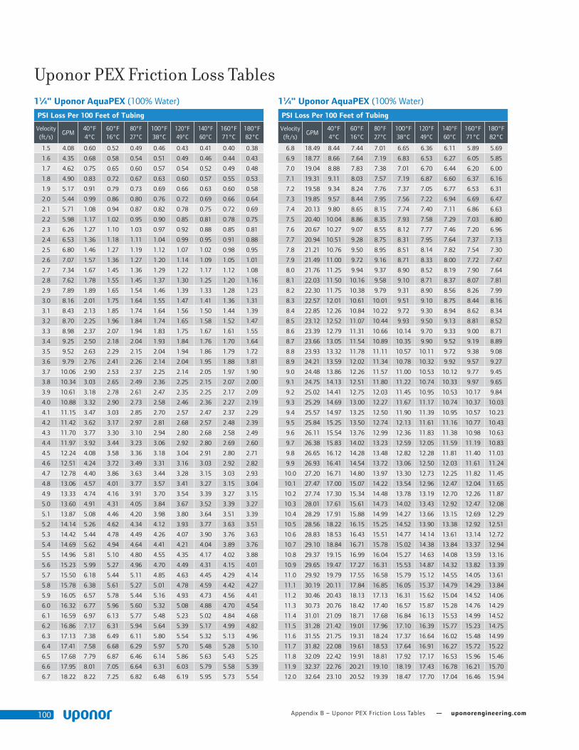
Appendix B – Uponor PEX Friction Loss Tables — uponorengineering.com100
11⁄4" Uponor AquaPEX (100% Water)
PSI Loss Per 100 Feet of Tubing
Velocity (ft/s)
GPM40°F 4°C
60°F 16°C
80°F 27°C
100°F 38°C
120°F 49°C
140°F 60°C
160°F 71°C
180°F 82°C
1.5 4.08 0.60 0.52 0.49 0.46 0.43 0.41 0.40 0.38
1.6 4.35 0.68 0.58 0.54 0.51 0.49 0.46 0.44 0.43
1.7 4.62 0.75 0.65 0.60 0.57 0.54 0.52 0.49 0.48
1.8 4.90 0.83 0.72 0.67 0.63 0.60 0.57 0.55 0.53
1.9 5.17 0.91 0.79 0.73 0.69 0.66 0.63 0.60 0.58
2.0 5.44 0.99 0.86 0.80 0.76 0.72 0.69 0.66 0.64
2.1 5.71 1.08 0.94 0.87 0.82 0.78 0.75 0.72 0.69
2.2 5.98 1.17 1.02 0.95 0.90 0.85 0.81 0.78 0.75
2.3 6.26 1.27 1.10 1.03 0.97 0.92 0.88 0.85 0.81
2.4 6.53 1.36 1.18 1.11 1.04 0.99 0.95 0.91 0.88
2.5 6.80 1.46 1.27 1.19 1.12 1.07 1.02 0.98 0.95
2.6 7.07 1.57 1.36 1.27 1.20 1.14 1.09 1.05 1.01
2.7 7.34 1.67 1.45 1.36 1.29 1.22 1.17 1.12 1.08
2.8 7.62 1.78 1.55 1.45 1.37 1.30 1.25 1.20 1.16
2.9 7.89 1.89 1.65 1.54 1.46 1.39 1.33 1.28 1.23
3.0 8.16 2.01 1.75 1.64 1.55 1.47 1.41 1.36 1.31
3.1 8.43 2.13 1.85 1.74 1.64 1.56 1.50 1.44 1.39
3.2 8.70 2.25 1.96 1.84 1.74 1.65 1.58 1.52 1.47
3.3 8.98 2.37 2.07 1.94 1.83 1.75 1.67 1.61 1.55
3.4 9.25 2.50 2.18 2.04 1.93 1.84 1.76 1.70 1.64
3.5 9.52 2.63 2.29 2.15 2.04 1.94 1.86 1.79 1.72
3.6 9.79 2.76 2.41 2.26 2.14 2.04 1.95 1.88 1.81
3.7 10.06 2.90 2.53 2.37 2.25 2.14 2.05 1.97 1.90
3.8 10.34 3.03 2.65 2.49 2.36 2.25 2.15 2.07 2.00
3.9 10.61 3.18 2.78 2.61 2.47 2.35 2.25 2.17 2.09
4.0 10.88 3.32 2.90 2.73 2.58 2.46 2.36 2.27 2.19
4.1 11.15 3.47 3.03 2.85 2.70 2.57 2.47 2.37 2.29
4.2 11.42 3.62 3.17 2.97 2.81 2.68 2.57 2.48 2.39
4.3 11.70 3.77 3.30 3.10 2.94 2.80 2.68 2.58 2.49
4.4 11.97 3.92 3.44 3.23 3.06 2.92 2.80 2.69 2.60
4.5 12.24 4.08 3.58 3.36 3.18 3.04 2.91 2.80 2.71
4.6 12.51 4.24 3.72 3.49 3.31 3.16 3.03 2.92 2.82
4.7 12.78 4.40 3.86 3.63 3.44 3.28 3.15 3.03 2.93
4.8 13.06 4.57 4.01 3.77 3.57 3.41 3.27 3.15 3.04
4.9 13.33 4.74 4.16 3.91 3.70 3.54 3.39 3.27 3.15
5.0 13.60 4.91 4.31 4.05 3.84 3.67 3.52 3.39 3.27
5.1 13.87 5.08 4.46 4.20 3.98 3.80 3.64 3.51 3.39
5.2 14.14 5.26 4.62 4.34 4.12 3.93 3.77 3.63 3.51
5.3 14.42 5.44 4.78 4.49 4.26 4.07 3.90 3.76 3.63
5.4 14.69 5.62 4.94 4.64 4.41 4.21 4.04 3.89 3.76
5.5 14.96 5.81 5.10 4.80 4.55 4.35 4.17 4.02 3.88
5.6 15.23 5.99 5.27 4.96 4.70 4.49 4.31 4.15 4.01
5.7 15.50 6.18 5.44 5.11 4.85 4.63 4.45 4.29 4.14
5.8 15.78 6.38 5.61 5.27 5.01 4.78 4.59 4.42 4.27
5.9 16.05 6.57 5.78 5.44 5.16 4.93 4.73 4.56 4.41
6.0 16.32 6.77 5.96 5.60 5.32 5.08 4.88 4.70 4.54
6.1 16.59 6.97 6.13 5.77 5.48 5.23 5.02 4.84 4.68
6.2 16.86 7.17 6.31 5.94 5.64 5.39 5.17 4.99 4.82
6.3 17.13 7.38 6.49 6.11 5.80 5.54 5.32 5.13 4.96
6.4 17.41 7.58 6.68 6.29 5.97 5.70 5.48 5.28 5.10
6.5 17.68 7.79 6.87 6.46 6.14 5.86 5.63 5.43 5.25
6.6 17.95 8.01 7.05 6.64 6.31 6.03 5.79 5.58 5.39
6.7 18.22 8.22 7.25 6.82 6.48 6.19 5.95 5.73 5.54
11⁄4" Uponor AquaPEX (100% Water)
PSI Loss Per 100 Feet of Tubing
Velocity (ft/s)
GPM40°F 4°C
60°F 16°C
80°F 27°C
100°F 38°C
120°F 49°C
140°F 60°C
160°F 71°C
180°F 82°C
6.8 18.49 8.44 7.44 7.01 6.65 6.36 6.11 5.89 5.69
6.9 18.77 8.66 7.64 7.19 6.83 6.53 6.27 6.05 5.85
7.0 19.04 8.88 7.83 7.38 7.01 6.70 6.44 6.20 6.00
7.1 19.31 9.11 8.03 7.57 7.19 6.87 6.60 6.37 6.16
7.2 19.58 9.34 8.24 7.76 7.37 7.05 6.77 6.53 6.31
7.3 19.85 9.57 8.44 7.95 7.56 7.22 6.94 6.69 6.47
7.4 20.13 9.80 8.65 8.15 7.74 7.40 7.11 6.86 6.63
7.5 20.40 10.04 8.86 8.35 7.93 7.58 7.29 7.03 6.80
7.6 20.67 10.27 9.07 8.55 8.12 7.77 7.46 7.20 6.96
7.7 20.94 10.51 9.28 8.75 8.31 7.95 7.64 7.37 7.13
7.8 21.21 10.76 9.50 8.95 8.51 8.14 7.82 7.54 7.30
7.9 21.49 11.00 9.72 9.16 8.71 8.33 8.00 7.72 7.47
8.0 21.76 11.25 9.94 9.37 8.90 8.52 8.19 7.90 7.64
8.1 22.03 11.50 10.16 9.58 9.10 8.71 8.37 8.07 7.81
8.2 22.30 11.75 10.38 9.79 9.31 8.90 8.56 8.26 7.99
8.3 22.57 12.01 10.61 10.01 9.51 9.10 8.75 8.44 8.16
8.4 22.85 12.26 10.84 10.22 9.72 9.30 8.94 8.62 8.34
8.5 23.12 12.52 11.07 10.44 9.93 9.50 9.13 8.81 8.52
8.6 23.39 12.79 11.31 10.66 10.14 9.70 9.33 9.00 8.71
8.7 23.66 13.05 11.54 10.89 10.35 9.90 9.52 9.19 8.89
8.8 23.93 13.32 11.78 11.11 10.57 10.11 9.72 9.38 9.08
8.9 24.21 13.59 12.02 11.34 10.78 10.32 9.92 9.57 9.27
9.0 24.48 13.86 12.26 11.57 11.00 10.53 10.12 9.77 9.45
9.1 24.75 14.13 12.51 11.80 11.22 10.74 10.33 9.97 9.65
9.2 25.02 14.41 12.75 12.03 11.45 10.95 10.53 10.17 9.84
9.3 25.29 14.69 13.00 12.27 11.67 11.17 10.74 10.37 10.03
9.4 25.57 14.97 13.25 12.50 11.90 11.39 10.95 10.57 10.23
9.5 25.84 15.25 13.50 12.74 12.13 11.61 11.16 10.77 10.43
9.6 26.11 15.54 13.76 12.99 12.36 11.83 11.38 10.98 10.63
9.7 26.38 15.83 14.02 13.23 12.59 12.05 11.59 11.19 10.83
9.8 26.65 16.12 14.28 13.48 12.82 12.28 11.81 11.40 11.03
9.9 26.93 16.41 14.54 13.72 13.06 12.50 12.03 11.61 11.24
10.0 27.20 16.71 14.80 13.97 13.30 12.73 12.25 11.82 11.45
10.1 27.47 17.00 15.07 14.22 13.54 12.96 12.47 12.04 11.65
10.2 27.74 17.30 15.34 14.48 13.78 13.19 12.70 12.26 11.87
10.3 28.01 17.61 15.61 14.73 14.02 13.43 12.92 12.47 12.08
10.4 28.29 17.91 15.88 14.99 14.27 13.66 13.15 12.69 12.29
10.5 28.56 18.22 16.15 15.25 14.52 13.90 13.38 12.92 12.51
10.6 28.83 18.53 16.43 15.51 14.77 14.14 13.61 13.14 12.72
10.7 29.10 18.84 16.71 15.78 15.02 14.38 13.84 13.37 12.94
10.8 29.37 19.15 16.99 16.04 15.27 14.63 14.08 13.59 13.16
10.9 29.65 19.47 17.27 16.31 15.53 14.87 14.32 13.82 13.39
11.0 29.92 19.79 17.55 16.58 15.79 15.12 14.55 14.05 13.61
11.1 30.19 20.11 17.84 16.85 16.05 15.37 14.79 14.29 13.84
11.2 30.46 20.43 18.13 17.13 16.31 15.62 15.04 14.52 14.06
11.3 30.73 20.76 18.42 17.40 16.57 15.87 15.28 14.76 14.29
11.4 31.01 21.09 18.71 17.68 16.84 16.13 15.53 14.99 14.52
11.5 31.28 21.42 19.01 17.96 17.10 16.39 15.77 15.23 14.75
11.6 31.55 21.75 19.31 18.24 17.37 16.64 16.02 15.48 14.99
11.7 31.82 22.08 19.61 18.53 17.64 16.91 16.27 15.72 15.22
11.8 32.09 22.42 19.91 18.81 17.92 17.17 16.53 15.96 15.46
11.9 32.37 22.76 20.21 19.10 18.19 17.43 16.78 16.21 15.70
12.0 32.64 23.10 20.52 19.39 18.47 17.70 17.04 16.46 15.94
Uponor PEX Friction Loss Tables

Plumbing Design Assistance Manual — Appendix B – Uponor PEX Friction Loss Tables 101
11⁄2" Uponor AquaPEX (100% Water)
PSI Loss Per 100 Feet of Tubing
Velocity (ft/s)
GPM40°F 4°C
60°F 16°C
80°F 27°C
100°F 38°C
120°F 49°C
140°F 60°C
160°F 71°C
180°F 82°C
1.5 5.68 0.49 0.42 0.39 0.37 0.35 0.34 0.32 0.31
1.6 6.06 0.55 0.47 0.44 0.42 0.40 0.38 0.36 0.35
1.7 6.44 0.61 0.53 0.49 0.46 0.44 0.42 0.40 0.39
1.8 6.82 0.67 0.58 0.54 0.51 0.49 0.46 0.45 0.43
1.9 7.20 0.74 0.64 0.60 0.56 0.54 0.51 0.49 0.47
2.0 7.58 0.80 0.70 0.65 0.62 0.59 0.56 0.54 0.52
2.1 7.96 0.88 0.76 0.71 0.67 0.64 0.61 0.59 0.57
2.2 8.34 0.95 0.83 0.77 0.73 0.69 0.66 0.64 0.61
2.3 8.71 1.03 0.89 0.83 0.79 0.75 0.72 0.69 0.67
2.4 9.09 1.10 0.96 0.90 0.85 0.81 0.77 0.74 0.72
2.5 9.47 1.19 1.03 0.97 0.91 0.87 0.83 0.80 0.77
2.6 9.85 1.27 1.11 1.04 0.98 0.93 0.89 0.86 0.83
2.7 10.23 1.36 1.18 1.11 1.05 1.00 0.96 0.92 0.89
2.8 10.61 1.45 1.26 1.18 1.12 1.06 1.02 0.98 0.95
2.9 10.99 1.54 1.34 1.26 1.19 1.13 1.08 1.04 1.01
3.0 11.37 1.63 1.42 1.33 1.26 1.20 1.15 1.11 1.07
3.1 11.75 1.73 1.51 1.41 1.34 1.28 1.22 1.18 1.13
3.2 12.12 1.83 1.60 1.50 1.42 1.35 1.29 1.24 1.20
3.3 12.50 1.93 1.68 1.58 1.50 1.43 1.37 1.31 1.27
3.4 12.88 2.03 1.78 1.67 1.58 1.50 1.44 1.39 1.34
3.5 13.26 2.14 1.87 1.75 1.66 1.58 1.52 1.46 1.41
3.6 13.64 2.24 1.96 1.84 1.75 1.66 1.60 1.54 1.48
3.7 14.02 2.35 2.06 1.94 1.83 1.75 1.68 1.61 1.56
3.8 14.40 2.47 2.16 2.03 1.92 1.83 1.76 1.69 1.63
3.9 14.78 2.58 2.26 2.12 2.01 1.92 1.84 1.77 1.71
4.0 15.16 2.70 2.37 2.22 2.11 2.01 1.93 1.85 1.79
4.1 15.53 2.82 2.47 2.32 2.20 2.10 2.01 1.94 1.87
4.2 15.91 2.94 2.58 2.42 2.30 2.19 2.10 2.02 1.96
4.3 16.29 3.06 2.69 2.53 2.40 2.29 2.19 2.11 2.04
4.4 16.67 3.19 2.80 2.63 2.50 2.38 2.29 2.20 2.13
4.5 17.05 3.32 2.91 2.74 2.60 2.48 2.38 2.29 2.21
4.6 17.43 3.45 3.03 2.85 2.70 2.58 2.48 2.38 2.30
4.7 17.81 3.58 3.15 2.96 2.81 2.68 2.57 2.48 2.39
4.8 18.19 3.72 3.27 3.07 2.92 2.78 2.67 2.57 2.49
4.9 18.57 3.86 3.39 3.19 3.03 2.89 2.77 2.67 2.58
5.0 18.94 4.00 3.51 3.31 3.14 2.99 2.87 2.77 2.68
5.1 19.32 4.14 3.64 3.42 3.25 3.10 2.98 2.87 2.77
5.2 19.70 4.28 3.77 3.54 3.36 3.21 3.08 2.97 2.87
5.3 20.08 4.43 3.90 3.67 3.48 3.32 3.19 3.08 2.97
5.4 20.46 4.58 4.03 3.79 3.60 3.44 3.30 3.18 3.07
5.5 20.84 4.73 4.16 3.92 3.72 3.55 3.41 3.29 3.18
5.6 21.22 4.88 4.30 4.05 3.84 3.67 3.52 3.40 3.28
5.7 21.60 5.03 4.44 4.18 3.96 3.79 3.64 3.51 3.39
5.8 21.98 5.19 4.57 4.31 4.09 3.91 3.75 3.62 3.50
5.9 22.35 5.35 4.72 4.44 4.22 4.03 3.87 3.73 3.61
6.0 22.73 5.51 4.86 4.58 4.35 4.15 3.99 3.85 3.72
6.1 23.11 5.67 5.00 4.71 4.48 4.28 4.11 3.96 3.83
6.2 23.49 5.84 5.15 4.85 4.61 4.41 4.23 4.08 3.94
6.3 23.87 6.01 5.30 4.99 4.74 4.53 4.36 4.20 4.06
6.4 24.25 6.18 5.45 5.13 4.88 4.66 4.48 4.32 4.18
6.5 24.63 6.35 5.60 5.28 5.02 4.80 4.61 4.44 4.30
6.6 25.01 6.52 5.76 5.43 5.16 4.93 4.74 4.57 4.42
6.7 25.38 6.70 5.91 5.57 5.30 5.06 4.87 4.69 4.54
11⁄2" Uponor AquaPEX (100% Water)
PSI Loss Per 100 Feet of Tubing
Velocity (ft/s)
GPM40°F 4°C
60°F 16°C
80°F 27°C
100°F 38°C
120°F 49°C
140°F 60°C
160°F 71°C
180°F 82°C
6.8 25.76 6.88 6.07 5.72 5.44 5.20 5.00 4.82 4.66
6.9 26.14 7.06 6.23 5.87 5.58 5.34 5.13 4.95 4.79
7.0 26.52 7.24 6.39 6.03 5.73 5.48 5.27 5.08 4.91
7.1 26.90 7.42 6.56 6.18 5.88 5.62 5.40 5.21 5.04
7.2 27.28 7.61 6.72 6.34 6.03 5.76 5.54 5.34 5.17
7.3 27.66 7.80 6.89 6.50 6.18 5.91 5.68 5.48 5.30
7.4 28.04 7.99 7.06 6.66 6.33 6.05 5.82 5.61 5.43
7.5 28.42 8.18 7.23 6.82 6.48 6.20 5.96 5.75 5.56
7.6 28.79 8.37 7.40 6.98 6.64 6.35 6.11 5.89 5.70
7.7 29.17 8.57 7.58 7.15 6.80 6.50 6.25 6.03 5.84
7.8 29.55 8.77 7.76 7.32 6.96 6.66 6.40 6.17 5.97
7.9 29.93 8.97 7.93 7.48 7.12 6.81 6.55 6.32 6.11
8.0 30.31 9.17 8.12 7.66 7.28 6.97 6.70 6.46 6.25
8.1 30.69 9.37 8.30 7.83 7.45 7.13 6.85 6.61 6.40
8.2 31.07 9.58 8.48 8.00 7.61 7.28 7.01 6.76 6.54
8.3 31.45 9.79 8.67 8.18 7.78 7.45 7.16 6.91 6.69
8.4 31.83 10.00 8.85 8.36 7.95 7.61 7.32 7.06 6.83
8.5 32.20 10.21 9.04 8.53 8.12 7.77 7.48 7.21 6.98
8.6 32.58 10.42 9.23 8.72 8.29 7.94 7.63 7.37 7.13
8.7 32.96 10.64 9.43 8.90 8.47 8.10 7.80 7.52 7.28
8.8 33.34 10.86 9.62 9.08 8.64 8.27 7.96 7.68 7.43
8.9 33.72 11.08 9.82 9.27 8.82 8.44 8.12 7.84 7.59
9.0 34.10 11.30 10.02 9.46 9.00 8.62 8.29 8.00 7.74
9.1 34.48 11.53 10.22 9.65 9.18 8.79 8.46 8.16 7.90
9.2 34.86 11.75 10.42 9.84 9.36 8.96 8.62 8.32 8.06
9.3 35.24 11.98 10.62 10.03 9.55 9.14 8.79 8.49 8.22
9.4 35.61 12.21 10.83 10.22 9.73 9.32 8.97 8.66 8.38
9.5 35.99 12.44 11.03 10.42 9.92 9.50 9.14 8.82 8.54
9.6 36.37 12.67 11.24 10.62 10.11 9.68 9.31 8.99 8.71
9.7 36.75 12.91 11.45 10.82 10.30 9.86 9.49 9.16 8.87
9.8 37.13 13.15 11.67 11.02 10.49 10.05 9.67 9.33 9.04
9.9 37.51 13.39 11.88 11.22 10.68 10.23 9.85 9.51 9.21
10.0 37.89 13.63 12.10 11.43 10.88 10.42 10.03 9.68 9.38
10.1 38.27 13.87 12.31 11.63 11.08 10.61 10.21 9.86 9.55
10.2 38.65 14.12 12.53 11.84 11.28 10.80 10.39 10.04 9.72
10.3 39.02 14.36 12.75 12.05 11.48 10.99 10.58 10.22 9.89
10.4 39.40 14.61 12.98 12.26 11.68 11.19 10.77 10.40 10.07
10.5 39.78 14.86 13.20 12.47 11.88 11.38 10.96 10.58 10.25
10.6 40.16 15.12 13.43 12.69 12.08 11.58 11.14 10.76 10.42
10.7 40.54 15.37 13.65 12.90 12.29 11.78 11.34 10.95 10.60
10.8 40.92 15.63 13.88 13.12 12.50 11.98 11.53 11.13 10.78
10.9 41.30 15.89 14.12 13.34 12.71 12.18 11.72 11.32 10.97
11.0 41.68 16.15 14.35 13.56 12.92 12.38 11.92 11.51 11.15
11.1 42.06 16.41 14.58 13.78 13.13 12.58 12.12 11.70 11.33
11.2 42.43 16.67 14.82 14.01 13.35 12.79 12.31 11.89 11.52
11.3 42.81 16.94 15.06 14.24 13.56 13.00 12.51 12.09 11.71
11.4 43.19 17.21 15.30 14.46 13.78 13.21 12.72 12.28 11.90
11.5 43.57 17.48 15.54 14.69 14.00 13.42 12.92 12.48 12.09
11.6 43.95 17.75 15.78 14.92 14.22 13.63 13.12 12.68 12.28
11.7 44.33 18.02 16.03 15.16 14.44 13.84 13.33 12.88 12.47
11.8 44.71 18.30 16.28 15.39 14.67 14.06 13.54 13.08 12.67
11.9 45.09 18.58 16.52 15.62 14.89 14.27 13.75 13.28 12.86
12.0 45.47 18.86 16.77 15.86 15.12 14.49 13.96 13.48 13.06
Uponor PEX Friction Loss Tables

Appendix B – Uponor PEX Friction Loss Tables — uponorengineering.com102
2" Uponor AquaPEX (100% Water)
PSI Loss Per 100 Feet of Tubing
Velocity (ft/s)
GPM40°F 4°C
60°F 16°C
80°F 27°C
100°F 38°C
120°F 49°C
140°F 60°C
160°F 71°C
180°F 82°C
1.5 9.75 0.35 0.30 0.28 0.27 0.25 0.24 0.23 0.22
1.6 10.39 0.39 0.34 0.32 0.30 0.28 0.27 0.26 0.25
1.7 11.04 0.43 0.38 0.35 0.33 0.32 0.30 0.29 0.28
1.8 11.69 0.48 0.41 0.39 0.37 0.35 0.33 0.32 0.31
1.9 12.34 0.52 0.46 0.43 0.40 0.38 0.37 0.35 0.34
2.0 12.99 0.57 0.50 0.47 0.44 0.42 0.40 0.39 0.37
2.1 13.64 0.62 0.54 0.51 0.48 0.46 0.44 0.42 0.41
2.2 14.29 0.68 0.59 0.55 0.52 0.50 0.48 0.46 0.44
2.3 14.94 0.73 0.64 0.60 0.57 0.54 0.52 0.50 0.48
2.4 15.59 0.79 0.69 0.64 0.61 0.58 0.56 0.54 0.52
2.5 16.24 0.85 0.74 0.69 0.66 0.63 0.60 0.58 0.56
2.6 16.89 0.91 0.79 0.74 0.70 0.67 0.64 0.62 0.60
2.7 17.54 0.97 0.85 0.79 0.75 0.72 0.69 0.66 0.64
2.8 18.19 1.03 0.90 0.85 0.80 0.77 0.73 0.71 0.68
2.9 18.84 1.10 0.96 0.90 0.85 0.81 0.78 0.75 0.73
3.0 19.49 1.16 1.02 0.96 0.91 0.87 0.83 0.80 0.77
3.1 20.14 1.23 1.08 1.02 0.96 0.92 0.88 0.85 0.82
3.2 20.79 1.30 1.14 1.07 1.02 0.97 0.93 0.90 0.87
3.3 21.44 1.38 1.21 1.13 1.08 1.03 0.98 0.95 0.91
3.4 22.09 1.45 1.27 1.20 1.13 1.08 1.04 1.00 0.97
3.5 22.74 1.53 1.34 1.26 1.19 1.14 1.09 1.05 1.02
3.6 23.39 1.60 1.41 1.32 1.26 1.20 1.15 1.11 1.07
3.7 24.04 1.68 1.48 1.39 1.32 1.26 1.21 1.16 1.12
3.8 24.69 1.76 1.55 1.46 1.38 1.32 1.27 1.22 1.18
3.9 25.34 1.85 1.62 1.53 1.45 1.38 1.33 1.28 1.24
4.0 25.99 1.93 1.70 1.60 1.52 1.45 1.39 1.34 1.29
4.1 26.64 2.02 1.77 1.67 1.58 1.51 1.45 1.40 1.35
4.2 27.29 2.10 1.85 1.74 1.65 1.58 1.52 1.46 1.41
4.3 27.94 2.19 1.93 1.82 1.72 1.65 1.58 1.52 1.47
4.4 28.59 2.28 2.01 1.89 1.80 1.72 1.65 1.59 1.54
4.5 29.24 2.38 2.09 1.97 1.87 1.79 1.72 1.65 1.60
4.6 29.89 2.47 2.18 2.05 1.95 1.86 1.79 1.72 1.66
4.7 30.54 2.57 2.26 2.13 2.02 1.93 1.86 1.79 1.73
4.8 31.18 2.66 2.35 2.21 2.10 2.01 1.93 1.86 1.80
4.9 31.83 2.76 2.44 2.29 2.18 2.08 2.00 1.93 1.86
5.0 32.48 2.86 2.53 2.38 2.26 2.16 2.07 2.00 1.93
5.1 33.13 2.96 2.62 2.46 2.34 2.24 2.15 2.07 2.00
5.2 33.78 3.07 2.71 2.55 2.42 2.32 2.23 2.15 2.08
5.3 34.43 3.17 2.80 2.64 2.51 2.40 2.30 2.22 2.15
5.4 35.08 3.28 2.90 2.73 2.59 2.48 2.38 2.30 2.22
5.5 35.73 3.39 2.99 2.82 2.68 2.56 2.46 2.37 2.30
5.6 36.38 3.50 3.09 2.91 2.77 2.65 2.54 2.45 2.37
5.7 37.03 3.61 3.19 3.01 2.86 2.73 2.63 2.53 2.45
5.8 37.68 3.72 3.29 3.10 2.95 2.82 2.71 2.61 2.53
5.9 38.33 3.84 3.39 3.20 3.04 2.91 2.80 2.70 2.61
6.0 38.98 3.95 3.49 3.30 3.13 3.00 2.88 2.78 2.69
6.1 39.63 4.07 3.60 3.39 3.23 3.09 2.97 2.86 2.77
6.2 40.28 4.19 3.71 3.50 3.32 3.18 3.06 2.95 2.85
6.3 40.93 4.31 3.81 3.60 3.42 3.27 3.15 3.03 2.94
6.4 41.58 4.43 3.92 3.70 3.52 3.37 3.24 3.12 3.02
6.5 42.23 4.55 4.03 3.80 3.62 3.46 3.33 3.21 3.11
6.6 42.88 4.68 4.14 3.91 3.72 3.56 3.42 3.30 3.19
6.7 43.53 4.81 4.26 4.02 3.82 3.66 3.52 3.39 3.28
2" Uponor AquaPEX (100% Water)
PSI Loss Per 100 Feet of Tubing
Velocity (ft/s)
GPM40°F 4°C
60°F 16°C
80°F 27°C
100°F 38°C
120°F 49°C
140°F 60°C
160°F 71°C
180°F 82°C
6.8 44.18 4.93 4.37 4.12 3.92 3.75 3.61 3.48 3.37
6.9 44.83 5.06 4.49 4.23 4.03 3.86 3.71 3.58 3.46
7.0 45.48 5.19 4.60 4.34 4.13 3.96 3.81 3.67 3.55
7.1 46.13 5.33 4.72 4.46 4.24 4.06 3.90 3.77 3.65
7.2 46.78 5.46 4.84 4.57 4.35 4.16 4.00 3.86 3.74
7.3 47.43 5.60 4.96 4.68 4.46 4.27 4.10 3.96 3.83
7.4 48.08 5.73 5.08 4.80 4.57 4.37 4.21 4.06 3.93
7.5 48.73 5.87 5.21 4.92 4.68 4.48 4.31 4.16 4.03
7.6 49.38 6.01 5.33 5.04 4.79 4.59 4.41 4.26 4.12
7.7 50.03 6.15 5.46 5.16 4.91 4.70 4.52 4.36 4.22
7.8 50.68 6.30 5.59 5.28 5.02 4.81 4.63 4.47 4.32
7.9 51.33 6.44 5.72 5.40 5.14 4.92 4.73 4.57 4.42
8.0 51.97 6.59 5.85 5.52 5.26 5.03 4.84 4.68 4.53
8.1 52.62 6.73 5.98 5.65 5.38 5.15 4.95 4.78 4.63
8.2 53.27 6.88 6.11 5.77 5.50 5.26 5.06 4.89 4.73
8.3 53.92 7.03 6.24 5.90 5.62 5.38 5.18 5.00 4.84
8.4 54.57 7.18 6.38 6.03 5.74 5.50 5.29 5.11 4.95
8.5 55.22 7.34 6.52 6.16 5.86 5.62 5.41 5.22 5.05
8.6 55.87 7.49 6.65 6.29 5.99 5.74 5.52 5.33 5.16
8.7 56.52 7.65 6.79 6.42 6.11 5.86 5.64 5.44 5.27
8.8 57.17 7.80 6.93 6.55 6.24 5.98 5.76 5.56 5.38
8.9 57.82 7.96 7.08 6.69 6.37 6.10 5.87 5.67 5.49
9.0 58.47 8.12 7.22 6.82 6.50 6.23 5.99 5.79 5.61
9.1 59.12 8.28 7.36 6.96 6.63 6.35 6.12 5.91 5.72
9.2 59.77 8.45 7.51 7.10 6.76 6.48 6.24 6.02 5.83
9.3 60.42 8.61 7.66 7.24 6.90 6.61 6.36 6.14 5.95
9.4 61.07 8.78 7.81 7.38 7.03 6.74 6.49 6.26 6.07
9.5 61.72 8.94 7.95 7.52 7.17 6.87 6.61 6.39 6.18
9.6 62.37 9.11 8.11 7.66 7.30 7.00 6.74 6.51 6.30
9.7 63.02 9.28 8.26 7.81 7.44 7.13 6.87 6.63 6.42
9.8 63.67 9.45 8.41 7.95 7.58 7.26 6.99 6.76 6.54
9.9 64.32 9.63 8.57 8.10 7.72 7.40 7.12 6.88 6.67
10.0 64.97 9.80 8.72 8.25 7.86 7.53 7.26 7.01 6.79
10.1 65.62 9.98 8.88 8.40 8.00 7.67 7.39 7.14 6.91
10.2 66.27 10.15 9.04 8.55 8.15 7.81 7.52 7.27 7.04
10.3 66.92 10.33 9.20 8.70 8.29 7.95 7.66 7.40 7.16
10.4 67.57 10.51 9.36 8.85 8.44 8.09 7.79 7.53 7.29
10.5 68.22 10.69 9.52 9.01 8.59 8.23 7.93 7.66 7.42
10.6 68.87 10.87 9.68 9.16 8.73 8.37 8.06 7.79 7.55
10.7 69.52 11.06 9.85 9.32 8.88 8.52 8.20 7.93 7.68
10.8 70.17 11.24 10.02 9.48 9.03 8.66 8.34 8.06 7.81
10.9 70.82 11.43 10.18 9.63 9.19 8.81 8.48 8.20 7.94
11.0 71.47 11.62 10.35 9.79 9.34 8.95 8.63 8.33 8.07
11.1 72.12 11.81 10.52 9.96 9.49 9.10 8.77 8.47 8.21
11.2 72.76 12.00 10.69 10.12 9.65 9.25 8.91 8.61 8.34
11.3 73.41 12.19 10.86 10.28 9.80 9.40 9.06 8.75 8.48
11.4 74.06 12.38 11.04 10.45 9.96 9.55 9.20 8.89 8.62
11.5 74.71 12.58 11.21 10.61 10.12 9.71 9.35 9.04 8.76
11.6 75.36 12.78 11.39 10.78 10.28 9.86 9.50 9.18 8.89
11.7 76.01 12.97 11.57 10.95 10.44 10.01 9.65 9.32 9.04
11.8 76.66 13.17 11.74 11.12 10.60 10.17 9.80 9.47 9.18
11.9 77.31 13.37 11.92 11.29 10.77 10.33 9.95 9.62 9.32
12.0 77.96 13.57 12.11 11.46 10.93 10.48 10.10 9.76 9.46
Uponor PEX Friction Loss Tables
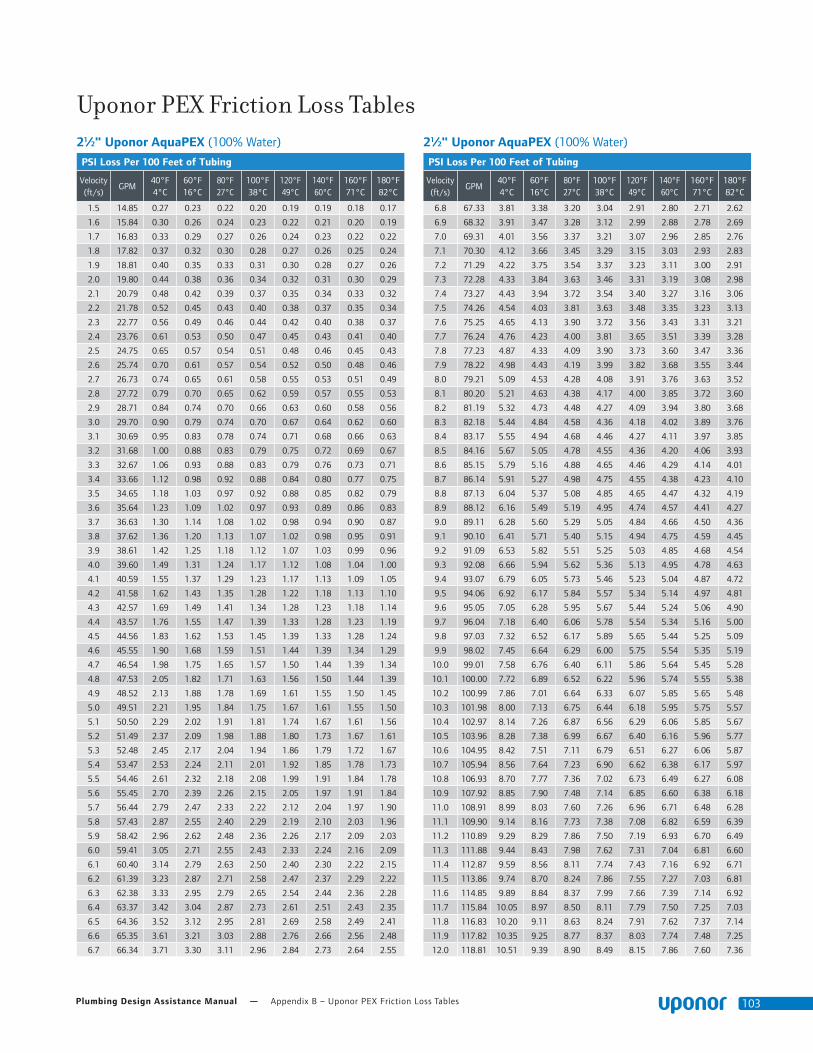
Plumbing Design Assistance Manual — Appendix B – Uponor PEX Friction Loss Tables 103
Uponor PEX Friction Loss Tables 21⁄2" Uponor AquaPEX (100% Water)
PSI Loss Per 100 Feet of Tubing
Velocity (ft/s)
GPM40°F 4°C
60°F 16°C
80°F 27°C
100°F 38°C
120°F 49°C
140°F 60°C
160°F 71°C
180°F 82°C
1.5 14.85 0.27 0.23 0.22 0.20 0.19 0.19 0.18 0.17
1.6 15.84 0.30 0.26 0.24 0.23 0.22 0.21 0.20 0.19
1.7 16.83 0.33 0.29 0.27 0.26 0.24 0.23 0.22 0.22
1.8 17.82 0.37 0.32 0.30 0.28 0.27 0.26 0.25 0.24
1.9 18.81 0.40 0.35 0.33 0.31 0.30 0.28 0.27 0.26
2.0 19.80 0.44 0.38 0.36 0.34 0.32 0.31 0.30 0.29
2.1 20.79 0.48 0.42 0.39 0.37 0.35 0.34 0.33 0.32
2.2 21.78 0.52 0.45 0.43 0.40 0.38 0.37 0.35 0.34
2.3 22.77 0.56 0.49 0.46 0.44 0.42 0.40 0.38 0.37
2.4 23.76 0.61 0.53 0.50 0.47 0.45 0.43 0.41 0.40
2.5 24.75 0.65 0.57 0.54 0.51 0.48 0.46 0.45 0.43
2.6 25.74 0.70 0.61 0.57 0.54 0.52 0.50 0.48 0.46
2.7 26.73 0.74 0.65 0.61 0.58 0.55 0.53 0.51 0.49
2.8 27.72 0.79 0.70 0.65 0.62 0.59 0.57 0.55 0.53
2.9 28.71 0.84 0.74 0.70 0.66 0.63 0.60 0.58 0.56
3.0 29.70 0.90 0.79 0.74 0.70 0.67 0.64 0.62 0.60
3.1 30.69 0.95 0.83 0.78 0.74 0.71 0.68 0.66 0.63
3.2 31.68 1.00 0.88 0.83 0.79 0.75 0.72 0.69 0.67
3.3 32.67 1.06 0.93 0.88 0.83 0.79 0.76 0.73 0.71
3.4 33.66 1.12 0.98 0.92 0.88 0.84 0.80 0.77 0.75
3.5 34.65 1.18 1.03 0.97 0.92 0.88 0.85 0.82 0.79
3.6 35.64 1.23 1.09 1.02 0.97 0.93 0.89 0.86 0.83
3.7 36.63 1.30 1.14 1.08 1.02 0.98 0.94 0.90 0.87
3.8 37.62 1.36 1.20 1.13 1.07 1.02 0.98 0.95 0.91
3.9 38.61 1.42 1.25 1.18 1.12 1.07 1.03 0.99 0.96
4.0 39.60 1.49 1.31 1.24 1.17 1.12 1.08 1.04 1.00
4.1 40.59 1.55 1.37 1.29 1.23 1.17 1.13 1.09 1.05
4.2 41.58 1.62 1.43 1.35 1.28 1.22 1.18 1.13 1.10
4.3 42.57 1.69 1.49 1.41 1.34 1.28 1.23 1.18 1.14
4.4 43.57 1.76 1.55 1.47 1.39 1.33 1.28 1.23 1.19
4.5 44.56 1.83 1.62 1.53 1.45 1.39 1.33 1.28 1.24
4.6 45.55 1.90 1.68 1.59 1.51 1.44 1.39 1.34 1.29
4.7 46.54 1.98 1.75 1.65 1.57 1.50 1.44 1.39 1.34
4.8 47.53 2.05 1.82 1.71 1.63 1.56 1.50 1.44 1.39
4.9 48.52 2.13 1.88 1.78 1.69 1.61 1.55 1.50 1.45
5.0 49.51 2.21 1.95 1.84 1.75 1.67 1.61 1.55 1.50
5.1 50.50 2.29 2.02 1.91 1.81 1.74 1.67 1.61 1.56
5.2 51.49 2.37 2.09 1.98 1.88 1.80 1.73 1.67 1.61
5.3 52.48 2.45 2.17 2.04 1.94 1.86 1.79 1.72 1.67
5.4 53.47 2.53 2.24 2.11 2.01 1.92 1.85 1.78 1.73
5.5 54.46 2.61 2.32 2.18 2.08 1.99 1.91 1.84 1.78
5.6 55.45 2.70 2.39 2.26 2.15 2.05 1.97 1.91 1.84
5.7 56.44 2.79 2.47 2.33 2.22 2.12 2.04 1.97 1.90
5.8 57.43 2.87 2.55 2.40 2.29 2.19 2.10 2.03 1.96
5.9 58.42 2.96 2.62 2.48 2.36 2.26 2.17 2.09 2.03
6.0 59.41 3.05 2.71 2.55 2.43 2.33 2.24 2.16 2.09
6.1 60.40 3.14 2.79 2.63 2.50 2.40 2.30 2.22 2.15
6.2 61.39 3.23 2.87 2.71 2.58 2.47 2.37 2.29 2.22
6.3 62.38 3.33 2.95 2.79 2.65 2.54 2.44 2.36 2.28
6.4 63.37 3.42 3.04 2.87 2.73 2.61 2.51 2.43 2.35
6.5 64.36 3.52 3.12 2.95 2.81 2.69 2.58 2.49 2.41
6.6 65.35 3.61 3.21 3.03 2.88 2.76 2.66 2.56 2.48
6.7 66.34 3.71 3.30 3.11 2.96 2.84 2.73 2.64 2.55
21⁄2" Uponor AquaPEX (100% Water)
PSI Loss Per 100 Feet of Tubing
Velocity (ft/s)
GPM40°F 4°C
60°F 16°C
80°F 27°C
100°F 38°C
120°F 49°C
140°F 60°C
160°F 71°C
180°F 82°C
6.8 67.33 3.81 3.38 3.20 3.04 2.91 2.80 2.71 2.62
6.9 68.32 3.91 3.47 3.28 3.12 2.99 2.88 2.78 2.69
7.0 69.31 4.01 3.56 3.37 3.21 3.07 2.96 2.85 2.76
7.1 70.30 4.12 3.66 3.45 3.29 3.15 3.03 2.93 2.83
7.2 71.29 4.22 3.75 3.54 3.37 3.23 3.11 3.00 2.91
7.3 72.28 4.33 3.84 3.63 3.46 3.31 3.19 3.08 2.98
7.4 73.27 4.43 3.94 3.72 3.54 3.40 3.27 3.16 3.06
7.5 74.26 4.54 4.03 3.81 3.63 3.48 3.35 3.23 3.13
7.6 75.25 4.65 4.13 3.90 3.72 3.56 3.43 3.31 3.21
7.7 76.24 4.76 4.23 4.00 3.81 3.65 3.51 3.39 3.28
7.8 77.23 4.87 4.33 4.09 3.90 3.73 3.60 3.47 3.36
7.9 78.22 4.98 4.43 4.19 3.99 3.82 3.68 3.55 3.44
8.0 79.21 5.09 4.53 4.28 4.08 3.91 3.76 3.63 3.52
8.1 80.20 5.21 4.63 4.38 4.17 4.00 3.85 3.72 3.60
8.2 81.19 5.32 4.73 4.48 4.27 4.09 3.94 3.80 3.68
8.3 82.18 5.44 4.84 4.58 4.36 4.18 4.02 3.89 3.76
8.4 83.17 5.55 4.94 4.68 4.46 4.27 4.11 3.97 3.85
8.5 84.16 5.67 5.05 4.78 4.55 4.36 4.20 4.06 3.93
8.6 85.15 5.79 5.16 4.88 4.65 4.46 4.29 4.14 4.01
8.7 86.14 5.91 5.27 4.98 4.75 4.55 4.38 4.23 4.10
8.8 87.13 6.04 5.37 5.08 4.85 4.65 4.47 4.32 4.19
8.9 88.12 6.16 5.49 5.19 4.95 4.74 4.57 4.41 4.27
9.0 89.11 6.28 5.60 5.29 5.05 4.84 4.66 4.50 4.36
9.1 90.10 6.41 5.71 5.40 5.15 4.94 4.75 4.59 4.45
9.2 91.09 6.53 5.82 5.51 5.25 5.03 4.85 4.68 4.54
9.3 92.08 6.66 5.94 5.62 5.36 5.13 4.95 4.78 4.63
9.4 93.07 6.79 6.05 5.73 5.46 5.23 5.04 4.87 4.72
9.5 94.06 6.92 6.17 5.84 5.57 5.34 5.14 4.97 4.81
9.6 95.05 7.05 6.28 5.95 5.67 5.44 5.24 5.06 4.90
9.7 96.04 7.18 6.40 6.06 5.78 5.54 5.34 5.16 5.00
9.8 97.03 7.32 6.52 6.17 5.89 5.65 5.44 5.25 5.09
9.9 98.02 7.45 6.64 6.29 6.00 5.75 5.54 5.35 5.19
10.0 99.01 7.58 6.76 6.40 6.11 5.86 5.64 5.45 5.28
10.1 100.00 7.72 6.89 6.52 6.22 5.96 5.74 5.55 5.38
10.2 100.99 7.86 7.01 6.64 6.33 6.07 5.85 5.65 5.48
10.3 101.98 8.00 7.13 6.75 6.44 6.18 5.95 5.75 5.57
10.4 102.97 8.14 7.26 6.87 6.56 6.29 6.06 5.85 5.67
10.5 103.96 8.28 7.38 6.99 6.67 6.40 6.16 5.96 5.77
10.6 104.95 8.42 7.51 7.11 6.79 6.51 6.27 6.06 5.87
10.7 105.94 8.56 7.64 7.23 6.90 6.62 6.38 6.17 5.97
10.8 106.93 8.70 7.77 7.36 7.02 6.73 6.49 6.27 6.08
10.9 107.92 8.85 7.90 7.48 7.14 6.85 6.60 6.38 6.18
11.0 108.91 8.99 8.03 7.60 7.26 6.96 6.71 6.48 6.28
11.1 109.90 9.14 8.16 7.73 7.38 7.08 6.82 6.59 6.39
11.2 110.89 9.29 8.29 7.86 7.50 7.19 6.93 6.70 6.49
11.3 111.88 9.44 8.43 7.98 7.62 7.31 7.04 6.81 6.60
11.4 112.87 9.59 8.56 8.11 7.74 7.43 7.16 6.92 6.71
11.5 113.86 9.74 8.70 8.24 7.86 7.55 7.27 7.03 6.81
11.6 114.85 9.89 8.84 8.37 7.99 7.66 7.39 7.14 6.92
11.7 115.84 10.05 8.97 8.50 8.11 7.79 7.50 7.25 7.03
11.8 116.83 10.20 9.11 8.63 8.24 7.91 7.62 7.37 7.14
11.9 117.82 10.35 9.25 8.77 8.37 8.03 7.74 7.48 7.25
12.0 118.81 10.51 9.39 8.90 8.49 8.15 7.86 7.60 7.36

Appendix B – Uponor PEX Friction Loss Tables — uponorengineering.com104
3" Uponor AquaPEX (100% Water)
PSI Loss Per 100 Feet of Tubing
Velocity (ft/s)
GPM40°F 4°C
60°F 16°C
80°F 27°C
100°F 38°C
120°F 49°C
140°F 60°C
160°F 71°C
180°F 82°C
1.5 21.12 0.21 0.19 0.17 0.16 0.16 0.15 0.14 0.14
1.6 22.53 0.24 0.21 0.20 0.18 0.18 0.17 0.16 0.16
1.7 23.93 0.27 0.23 0.22 0.21 0.20 0.19 0.18 0.17
1.8 25.34 0.29 0.26 0.24 0.23 0.22 0.21 0.20 0.19
1.9 26.75 0.32 0.28 0.26 0.25 0.24 0.23 0.22 0.21
2.0 28.16 0.35 0.31 0.29 0.27 0.26 0.25 0.24 0.23
2.1 29.57 0.38 0.34 0.32 0.30 0.29 0.27 0.26 0.25
2.2 30.97 0.42 0.37 0.34 0.33 0.31 0.30 0.29 0.28
2.3 32.38 0.45 0.40 0.37 0.35 0.34 0.32 0.31 0.30
2.4 33.79 0.49 0.43 0.40 0.38 0.36 0.35 0.34 0.32
2.5 35.20 0.52 0.46 0.43 0.41 0.39 0.37 0.36 0.35
2.6 36.60 0.56 0.49 0.46 0.44 0.42 0.40 0.39 0.37
2.7 38.01 0.60 0.53 0.49 0.47 0.45 0.43 0.41 0.40
2.8 39.42 0.64 0.56 0.53 0.50 0.48 0.46 0.44 0.43
2.9 40.83 0.68 0.60 0.56 0.53 0.51 0.49 0.47 0.45
3.0 42.24 0.72 0.63 0.60 0.57 0.54 0.52 0.50 0.48
3.1 43.64 0.76 0.67 0.63 0.60 0.57 0.55 0.53 0.51
3.2 45.05 0.81 0.71 0.67 0.64 0.61 0.58 0.56 0.54
3.3 46.46 0.85 0.75 0.71 0.67 0.64 0.62 0.59 0.57
3.4 47.87 0.90 0.79 0.75 0.71 0.68 0.65 0.63 0.61
3.5 49.28 0.95 0.83 0.79 0.75 0.71 0.69 0.66 0.64
3.6 50.68 0.99 0.88 0.83 0.79 0.75 0.72 0.69 0.67
3.7 52.09 1.04 0.92 0.87 0.82 0.79 0.76 0.73 0.71
3.8 53.50 1.09 0.97 0.91 0.87 0.83 0.79 0.77 0.74
3.9 54.91 1.15 1.01 0.95 0.91 0.87 0.83 0.80 0.78
4.0 56.31 1.20 1.06 1.00 0.95 0.91 0.87 0.84 0.81
4.1 57.72 1.25 1.11 1.04 0.99 0.95 0.91 0.88 0.85
4.2 59.13 1.31 1.15 1.09 1.04 0.99 0.95 0.92 0.89
4.3 60.54 1.36 1.20 1.14 1.08 1.03 0.99 0.96 0.93
4.4 61.95 1.42 1.25 1.18 1.13 1.08 1.03 1.00 0.97
4.5 63.35 1.48 1.31 1.23 1.17 1.12 1.08 1.04 1.01
4.6 64.76 1.53 1.36 1.28 1.22 1.17 1.12 1.08 1.05
4.7 66.17 1.59 1.41 1.33 1.27 1.21 1.17 1.12 1.09
4.8 67.58 1.65 1.47 1.38 1.32 1.26 1.21 1.17 1.13
4.9 68.99 1.72 1.52 1.44 1.37 1.31 1.26 1.21 1.17
5.0 70.39 1.78 1.58 1.49 1.42 1.36 1.30 1.26 1.22
5.1 71.80 1.84 1.63 1.54 1.47 1.40 1.35 1.30 1.26
5.2 73.21 1.91 1.69 1.60 1.52 1.45 1.40 1.35 1.31
5.3 74.62 1.97 1.75 1.65 1.57 1.51 1.45 1.40 1.35
5.4 76.02 2.04 1.81 1.71 1.63 1.56 1.50 1.45 1.40
5.5 77.43 2.11 1.87 1.77 1.68 1.61 1.55 1.49 1.45
5.6 78.84 2.18 1.93 1.82 1.74 1.66 1.60 1.54 1.49
5.7 80.25 2.25 1.99 1.88 1.79 1.72 1.65 1.59 1.54
5.8 81.66 2.32 2.06 1.94 1.85 1.77 1.70 1.64 1.59
5.9 83.06 2.39 2.12 2.00 1.91 1.83 1.76 1.70 1.64
6.0 84.47 2.46 2.19 2.06 1.97 1.88 1.81 1.75 1.69
6.1 85.88 2.53 2.25 2.13 2.03 1.94 1.87 1.80 1.74
6.2 87.29 2.61 2.32 2.19 2.09 2.00 1.92 1.86 1.80
6.3 88.70 2.68 2.39 2.25 2.15 2.06 1.98 1.91 1.85
6.4 90.10 2.76 2.45 2.32 2.21 2.12 2.04 1.97 1.90
6.5 91.51 2.84 2.52 2.38 2.27 2.18 2.09 2.02 1.96
6.6 92.92 2.92 2.59 2.45 2.33 2.24 2.15 2.08 2.01
6.7 94.33 2.99 2.66 2.52 2.40 2.30 2.21 2.14 2.07
3" Uponor AquaPEX (100% Water)
PSI Loss Per 100 Feet of Tubing
Velocity (ft/s)
GPM40°F 4°C
60°F 16°C
80°F 27°C
100°F 38°C
120°F 49°C
140°F 60°C
160°F 71°C
180°F 82°C
6.8 95.73 3.08 2.74 2.59 2.46 2.36 2.27 2.19 2.12
6.9 97.14 3.16 2.81 2.65 2.53 2.42 2.33 2.25 2.18
7.0 98.55 3.24 2.88 2.72 2.60 2.49 2.39 2.31 2.24
7.1 99.96 3.32 2.96 2.80 2.66 2.55 2.46 2.37 2.30
7.2 101.37 3.41 3.03 2.87 2.73 2.62 2.52 2.43 2.36
7.3 102.77 3.49 3.11 2.94 2.80 2.68 2.58 2.50 2.42
7.4 104.18 3.58 3.18 3.01 2.87 2.75 2.65 2.56 2.48
7.5 105.59 3.66 3.26 3.09 2.94 2.82 2.71 2.62 2.54
7.6 107.00 3.75 3.34 3.16 3.01 2.89 2.78 2.68 2.60
7.7 108.41 3.84 3.42 3.23 3.08 2.96 2.85 2.75 2.66
7.8 109.81 3.93 3.50 3.31 3.16 3.03 2.91 2.81 2.73
7.9 111.22 4.02 3.58 3.39 3.23 3.10 2.98 2.88 2.79
8.0 112.63 4.11 3.66 3.47 3.30 3.17 3.05 2.95 2.85
8.1 114.04 4.20 3.75 3.54 3.38 3.24 3.12 3.01 2.92
8.2 115.44 4.30 3.83 3.62 3.45 3.31 3.19 3.08 2.99
8.3 116.85 4.39 3.91 3.70 3.53 3.39 3.26 3.15 3.05
8.4 118.26 4.48 4.00 3.78 3.61 3.46 3.33 3.22 3.12
8.5 119.67 4.58 4.08 3.87 3.69 3.54 3.41 3.29 3.19
8.6 121.08 4.68 4.17 3.95 3.77 3.61 3.48 3.36 3.26
8.7 122.48 4.77 4.26 4.03 3.85 3.69 3.55 3.43 3.33
8.8 123.89 4.87 4.35 4.12 3.93 3.76 3.63 3.50 3.40
8.9 125.30 4.97 4.44 4.20 4.01 3.84 3.70 3.58 3.47
9.0 126.71 5.07 4.53 4.29 4.09 3.92 3.78 3.65 3.54
9.1 128.12 5.17 4.62 4.37 4.17 4.00 3.85 3.72 3.61
9.2 129.52 5.28 4.71 4.46 4.25 4.08 3.93 3.80 3.68
9.3 130.93 5.38 4.80 4.55 4.34 4.16 4.01 3.88 3.76
9.4 132.34 5.48 4.90 4.64 4.42 4.24 4.09 3.95 3.83
9.5 133.75 5.59 4.99 4.73 4.51 4.33 4.17 4.03 3.90
9.6 135.15 5.69 5.09 4.82 4.60 4.41 4.25 4.11 3.98
9.7 136.56 5.80 5.18 4.91 4.68 4.49 4.33 4.18 4.05
9.8 137.97 5.91 5.28 5.00 4.77 4.58 4.41 4.26 4.13
9.9 139.38 6.02 5.38 5.09 4.86 4.66 4.49 4.34 4.21
10.0 140.79 6.13 5.47 5.18 4.95 4.75 4.57 4.42 4.29
10.1 142.19 6.24 5.57 5.28 5.04 4.83 4.66 4.50 4.36
10.2 143.60 6.35 5.67 5.37 5.13 4.92 4.74 4.58 4.44
10.3 145.01 6.46 5.77 5.47 5.22 5.01 4.83 4.67 4.52
10.4 146.42 6.57 5.87 5.57 5.31 5.10 4.91 4.75 4.60
10.5 147.83 6.69 5.98 5.66 5.40 5.19 5.00 4.83 4.68
10.6 149.23 6.80 6.08 5.76 5.50 5.28 5.09 4.92 4.77
10.7 150.64 6.92 6.18 5.86 5.59 5.37 5.17 5.00 4.85
10.8 152.05 7.03 6.29 5.96 5.69 5.46 5.26 5.09 4.93
10.9 153.46 7.15 6.39 6.06 5.78 5.55 5.35 5.17 5.02
11.0 154.86 7.27 6.50 6.16 5.88 5.64 5.44 5.26 5.10
11.1 156.27 7.39 6.61 6.26 5.98 5.74 5.53 5.35 5.18
11.2 157.68 7.51 6.71 6.36 6.08 5.83 5.62 5.44 5.27
11.3 159.09 7.63 6.82 6.47 6.17 5.93 5.71 5.53 5.36
11.4 160.50 7.75 6.93 6.57 6.27 6.02 5.81 5.61 5.44
11.5 161.90 7.87 7.04 6.68 6.37 6.12 5.90 5.70 5.53
11.6 163.31 7.99 7.15 6.78 6.47 6.22 5.99 5.80 5.62
11.7 164.72 8.12 7.26 6.89 6.58 6.31 6.09 5.89 5.71
11.8 166.13 8.24 7.38 6.99 6.68 6.41 6.18 5.98 5.80
11.9 167.54 8.37 7.49 7.10 6.78 6.51 6.28 6.07 5.89
12.0 168.94 8.50 7.60 7.21 6.89 6.61 6.37 6.17 5.98
Uponor PEX Friction Loss Tables

Plumbing Design Assistance Manual — Appendix C – Fitting Equivalent Length 105
Appendix C
Fitting Equivalent LengthEquivalent Length of FittingsThis section provides the equivalent length of piping pressure loss for several ProPEX fittings. The equivalent length is used to approximate the impact the fittings have on pressure loss across the piping length. The equivalent length for each fitting is shown in the tables below. Add the equivalent length to the total piping length for each fitting installed along the piping run. The total pressure loss is then computed from the adjusted total piping length. Equivalent lengths are commonly utilized to calculate the Total Developed Length (TDL) along a critical piping path. All Uponor values represent pressure loss at 8 ft./sec.
Many methods exist for calculating the coefficient of velocity (Cv) across valves and fittings. The proceeding set of Uponor data was derived from empirical testing performed by NSF International and tested to ISA-S75.02 Pressure Drop Measurement and Cv Calculations at a measured and verified flow rate. In order to calculate equivalent length in feet, a quadratic equation is utilized to determine pressure drop versus flow data at precisely 8 ft./sec.
Other common methods for calculating Cv include UL 1821 Thermoplastic Sprinkler Pipe and Fittings for Fire Protection and the use of flow modeling software. Through extensive testing and validation by NSF International, Uponor has built a complete and accurate data set for AquaPEX Plumbing Systems.
When comparing equivalent length data across PEX fitting manufacturers, values may differ due to different testing methods and reported values at specific flow velocities other than 8 ft./sec.
For comparison purposes, NSF International tested commonly available ASTM F1807 Brass Insert Fittings Utilizing Copper Crimp Ring for PEX Tubing Fittings and ASTM F2159 Plastic Insert Fittings Utilizing Copper Crimp Rings for PEX Tubing Fittings to the ISA-S75.02 test method using the same quadratic equation as the Uponor ProPEX Fittings to determine pressure drop versus flow data at precisely 8 ft./sec. Reference Table C-1 for equivalent length comparisons.
FittingsNominal Size (in)
ASTM F1960 ASTM F 1807 ASTM F 2159F1960
vs F1807
F1960 vs
F2159
Uponor ProPEX
Eq. Length
Brass Crimp Ring Eq. Length
Plastic Crimp Ring Eq. Length
Tee-Run
1⁄2 1 3.19 6.03 219.00% 503.00%
3⁄4 1.5 2.57 6.12 71.33% 308.00%
1 1.3 2.49 6.26 91.54% 381.54%
Tee-Branch
1⁄2 6.3 9.05 15.34 43.65% 143.49%
3⁄4 15.6 10.16 17.04 -34.87% 9.23%
1 12.7 11.87 20.17 -6.54% 58.82%
Elbow
1⁄2 10.4 9.11 13.53 -12.40% 30.10%
3⁄4 10.8 10.47 16.21 -3.06% 50.09%
1 11.5 10.14 17.05 -11.83% 48.26%
Coupling
1⁄2 0.8 2.03 6.55 153.75% 718.75%
3⁄4 0.9 2.18 5.64 142.22% 526.67%
1 0.9 1.49 4.97 65.56% 452.22%
Table C-1: Equivalent Length Comparison of Various PEX Fitting Types

Appendix C – Fitting Equivalent Length — uponorengineering.com106
EP Reducing Tees Flow/Port Avg. Cv Eq. Length (ft)
1⁄2 x 1⁄2 x 3⁄4 Branch 3.8 4.1
3⁄4 x 1⁄2 x 1⁄2
Through 4.6 3.5
Branch 3.4 6.4
3⁄4 x 1⁄2 x 3⁄4Through 5.4 2.3
Branch 5.4 16.1
3⁄4 x 3⁄4 x 1⁄2
Through 14.2 2.0
Branch 3.1 7.6
3⁄4 x 3⁄4 x 1 Branch 8.7 5.7
1 x 3⁄4 x 3⁄4Through 12.8 2.4
Branch 5.3 16.7
1 x 3⁄4 x 1Through 12.9 2.4
Branch 10.5 15.1
1 x 1 x 1⁄2
Through 32.2 1.2
Branch 3.4 6.5
1 x 1 x 3⁄4Through 27.8 1.7
Branch 8.2 6.4
11⁄4 x 1 x 3⁄4Through 21.0 3.4
Branch 9.3 5.2
11⁄4 x 1 x 1Through 11.7 11.0
Branch 8.4 23.0
EP Tees Flow/Port Avg. Cv Eq. Length (ft)
1⁄2 x 1⁄2 x 1⁄2
Through 7.7 1.0
Branch 3.4 6.3
3⁄4 x 3⁄4 x 3⁄4Through 15.7 1.5
Branch 5.4 15.6
1 x 1 x 1Through 30.5 1.3
Branch 11.3 12.7
11⁄4 x 11⁄4 x 11⁄4Through 34.0 3.8
Branch 23.9 8.6
11⁄2 x 11⁄2 x 11⁄2
Through 63.7 1.8
Branch 31.0 10.6
2 x 2 x 2Through 150.7 0.8
Branch 52.5 15.5
21⁄2 x 21⁄2 x 21⁄2
Through 197.2 2.7
Branch 81.5 22.3
3 x 3 x 3Through 286.6 2.8
Branch 122.8 23.9
EP Reducing Tees Flow/Port Avg. Cv Eq. Length (ft)
11⁄4 x 11⁄4 x 1⁄2
Through 45.2 1.9
Branch 4.1 3.9
11⁄4 x 11⁄4 x 3⁄4Through 43.4 2.3
Branch 8.9 5.7
11⁄4 x 11⁄4 x 1Through 33.0 4.2
Branch 15.8 6.3
11⁄2 x 1 x 3⁄4Through 19.5 4.0
Branch 9.3 5.1
11⁄2 x 1 x 1Through 18.9 4.3
Branch 15.6 6.5
11⁄2 x 1 x 11⁄2
Through 19.1 4.2
Branch 26.5 14.9
11⁄2 x 11⁄4 x 3⁄4Through 33.1 4.2
Branch 6.3 11.3
11⁄2 x 11⁄4 x 1Through 36.4 3.1
Branch 11.2 13.1
11⁄2 x 11⁄4 x 11⁄4Through 45.4 2.0
Branch 17.0 17.7
11⁄2 x 11⁄2 x 1⁄2
Through 60.5 2.4
Branch 3.4 6.3
11⁄2 x 11⁄2 x 3⁄4Through 56.0 2.9
Branch 9.0 5.4
11⁄2 x 11⁄2 x 1Through 53.8 3.1
Branch 15.3 6.9
11⁄2 x 11⁄2 x 11⁄4Through 54.3 3.2
Branch 33.7 4.1
2 x 11⁄2 x 3⁄4Through 43.5 4.9
Branch 8.4 6.2
2 x 11⁄2 x 1Through 42.4 5.5
Branch 13.9 8.4
2 x 11⁄2 x 11⁄4Through 41.8 5.6
Branch 22.0 10.3
2 x 11⁄2 x 11⁄2
Through 42.1 5.4
Branch 28.5 13.0
2 x 11⁄2 x 2Through 38.6 6.6
Branch 51.8 16.1
2 x 2 x 1⁄2
Through 111.1 2.7
Branch 4.3 4.0
2 x 2 x 3⁄4Through 115.0 2.7
Branch 8.2 6.8
Fitting Equivalent Length and Cv Data

Plumbing Design Assistance Manual — Appendix C – Fitting Equivalent Length 107
EP Reducing Tee EP Reducing Tees Flow Path Avg. Cv Eq. Length (ft)
2 x 2 x 1Through 119.7 2.4
Branch 13.8 8.5
2 x 2 x 11⁄4Through 107.0 3.1
Branch 23.6 8.8
2 x 2 x 11⁄2
Through 115.8 2.5
Branch 29.9 11.7
21⁄2 x 2 x 11⁄2
Through 80.4 5.9
Branch 30.2 11.2
21⁄2 x 2 x 2Through 79.5 5.7
Branch 51.8 16.0
21⁄2 x 21⁄2 x 3⁄4Through 209.6 2.0
Branch 8.5 6.0
21⁄2 x 21⁄2 x 1Through 202.0 2.4
Branch 17.5 5.0
21⁄2 x 21⁄2 x 11⁄4Through 198.8 2.5
Branch 22.4 9.7
21⁄2 x 21⁄2 x 11⁄2
Through 200.0 2.5
Branch 29.8 11.5
21⁄2 x 21⁄2 x 2Through 193.2 2.7
Branch 53.6 14.7
3 x 2 x 2Through 69.9 8.1
Branch 52.8 15.3
3 x 21⁄2 x 11⁄2Through 132.5 7.5
Branch 29.2 12.0
3 x 21⁄2 x 2Through 133.2 7.4
Branch 51.7 16.4
3 x 3 x 3⁄4Through 294.9 2.7
Branch 8.5 6.0
3 x 3 x 1Through 291.4 2.8
Branch 14.8 7.3
3 x 3 x 11⁄4Through 290.4 3.0
Branch 22.8 9.3
3 x 3 x 11⁄2Through 290.5 2.9
Branch 29.9 11.3
3 x 3 x 2Through 287.6 3.0
Branch 53.8 14.6
3 x 3 x 21⁄2Through 288.3 3.0
Branch 82.2 22.2

Appendix C – Fitting Equivalent Length — uponorengineering.com108
90º Elbow Nominal Size (in) Flow Path Avg. Cv Eq. Length (ft)
1⁄2 x 1⁄2 Through 2.6 10.43⁄4 x 3⁄4 Through 6.7 10.8
1 x 1 Through 11.9 11.5
11⁄4 x 11⁄4 Through 22.2 10.0
11⁄2 x 11⁄2 Through 29.7 11.5
2 x 2 Through 50.2 17.1
21⁄2 x 21⁄2 Through 86.0 20.0
3 x 3 Through 125.0 23.2
EP Coupling Nominal Size (in) Flow Path Avg. Cv Eq. Length (ft)
1⁄2 x 1⁄2 Through 8.3 0.83⁄4 x 1⁄2 Through 5.2 2.63⁄4 x 3⁄4 Through 19.0 0.9
1 x 3⁄4 Through 12.5 2.7
1 x 1 Through 33.8 0.9
11⁄4 x 3⁄4 Through 10.9 3.6
11⁄4 x 1 Through 22.3 2.6
11⁄4 x 11⁄4 Through 53.3 1.1
11⁄2 x 3⁄4 Through 10.8 3.5
11⁄2 x 1 Through 19.0 4.3
11⁄2 x 11⁄4 Through 33.9 3.7
11⁄2 x 11⁄2 Through 69.5 1.4
2 x 11⁄2 Through 45.2 4.6
2 x 2 Through 107.8 2.7
21⁄2 x 11⁄4 Through 29.3 5.4
21⁄2 x 11⁄2 Through 35.9 7.5
21⁄2 x 2 Through 82.6 5.4
21⁄2 x 21⁄2 Through 219.1 1.7
3 x 2 Through 73.4 7.2
3 x 21⁄2 Through 136.2 7.1
3 x 3 Through 320.6 1.9
45º Elbow Nominal Size (in) Flow Path Avg. Cv Eq. Length (ft)
11⁄2 x 11⁄2 Through 33.1 9.3
2 x 2 Through 68.9 8.8
21⁄2 x 21⁄2 Through 136.8 6.9
3 x 3 Through 195.5 8.3

Plumbing Design Assistance Manual — Appendix C – Fitting Equivalent Length 109
Elbows EP Multiport Elbows Flow/Port Avg. Cv Eq. Length (ft)
EP Flow-through Multiport Elbow, 3 outlets, 3⁄4" x 3⁄4" ProPEX
Through 7.1 8.8
#2 3.4 6.3
EP Flow-through Multiport Elbow, 4 outlets, 3⁄4" x 3⁄4" ProPEX
Through 7.1 8.9
#3 3.4 6.4
1" EP Branch Multiport Elbow, 10 outlets with mounting clips
#5 3.0 7.9
Vertical EP Flow-through Multiport Vertical Tee Flow/Port Avg. Cv Eq. Length (ft)
EP Flow-through Multiport Vertical Tee, 3 outlets, 3⁄4" x 3⁄4" x 3⁄4" ProPEX
Tee to Tee 13.6 2.3
Tee to Side 7.4 8.2
Tee to #2 3.1 7.8
Side to Tee 6.9 9.5
Side to #2 3.6 4.9
Flow-through EP Flow-through Multiport Tees Flow/Port Avg. Cv Eq. Length (ft)
EP Flow-through Multiport Tee, 2 outlets, 3⁄4" x 3⁄4" ProPEX
Through 15.3 1.6
#2 3.4 6.4
EP Flow-through Multiport Tee, 3 (1") outlets, 2" x 2" ProPEX
Through 99.0 3.9
#2 13.4 9.0
EP Flow-through Multiport Tee, 3 outlets, 1" x 3⁄4" PEX
Through 11.6 3.2
#2 3.7 5.4
EP Flow-through Multiport Tee, 3 outlets, 3⁄4" x 3⁄4" ProPEX
Through 7.1 8.8
#2 3.4 6.3
EP Flow-through Multiport Tee, 3 (3⁄4") outlets, 11⁄4" x 11⁄4" PEX
Through 45.9 7.9
#2 1.8 7.1
EP Flow-through Multiport Tee, 4 outlets, 3⁄4" x 3⁄4" ProPEX
Through 7.1 8.9
#3 3.4 6.4
EP Flow-through Multiport Tee, 4 outlets, 1" x 1" PEX
Through 29.3 1.5
#3 3.2 7.5
EP Flow-through Multiport Tee, 4 outlets, 1" x 3⁄4" ProPEX
Through 11.7 3.0
#3 4.0 4.5
EP Flow-through Multiport Tee, 6 outlets, 1" x 3⁄4" ProPEX
Through 11.8 3.1
#3 3.5 5.8
EP Flow-through Multiport Tee, 6 outlets, 3⁄4" x 3⁄4" ProPEX
Through 13.2 3.8
#3 3.7 5.3
EP Flow-through Multiport Tee, 6 outlets, 1" x 1" ProPEX
Through 25.1 2.5
#3 3.1 7.6
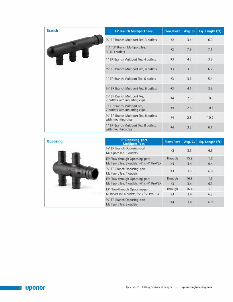
Appendix C – Fitting Equivalent Length — uponorengineering.com110
Branch EP Branch Multiport Tees Flow/Port Avg. Cv Eq. Length (ft)
3⁄4" EP Branch Multiport Tee, 3 outlets #2 3.4 6.0
11⁄4" EP Branch Multiport Tee, 3 (3⁄4") outlets
#2 7.9 7.1
1" EP Branch Multiport Tee, 4 outlets #3 4.2 3.9
3⁄4" EP Branch Multiport Tee, 4 outlets #3 3.3 6.7
1" EP Branch Multiport Tee, 6 outlets #3 3.6 5.4
3⁄4" EP Branch Multiport Tee, 6 outlets #3 4.1 3.8
3⁄4" EP Branch Multiport Tee, 7 outlets with mounting clips
#4 2.6 10.6
1" EP Branch Multiport Tee, 7 outlets with mounting clips
#4 2.6 10.7
3⁄4" EP Branch Multiport Tee, 8 outlets with mounting clips
#4 2.6 10.9
1" EP Branch Multiport Tee, 8 outlets with mounting clips
#4 3.2 6.1
Opposing EP Opposing-port Multiport Tees Flow/Port Avg. Cv Eq. Length (ft)
3⁄4" EP Branch Opposing-port Multiport Tee, 3 outlets
#2 3.3 6.5
EP Flow-through Opposing-port Multiport Tee, 3 outlets, 3⁄4" x 3⁄4" ProPEX
Through 15.9 1.6
#3 3.4 6.43⁄4" EP Branch Opposing-port Multiport Tee, 4 outlets
#3 3.5 6.0
EP Flow-through Opposing-port Multiport Tee, 4 outlets, 3⁄4" x 3⁄4" ProPEX
Through 16.9 1.3
#3 3.4 6.3
EP Flow-through Opposing-port Multiport Tee, 6 outlets, 3⁄4" x 3⁄4" ProPEX
Through 16.4 1.3
#3 3.4 6.23⁄4" EP Branch Opposing-port Multiport Tee, 8 outlets
#4 3.4 6.0

Plumbing Design Assistance Manual — Appendix C – Fitting Equivalent Length 111
Fitting Adapters Nominal Size (in) Flow Path Avg. Cv Eq. Length (ft)
1⁄2 PEX x 1⁄2 Copper Through 7.7 1.01⁄2 PEX x 3⁄4 Copper Cu to PEX 5.6 2.23⁄4 PEX x 1⁄2 Copper PEX to Cu 8.8 1.53⁄4 PEX x 3⁄4 Copper Through 15.7 1.53⁄4 PEX x 1 Copper Cu to PEX 11.4 3.1
1 PEX x 1 Copper Through 30.5 1.3
11⁄4 PEX x 11⁄4 Copper Through 34.0 3.8
11⁄2 PEX x 11⁄2 Copper Through 63.7 1.8
2 PEX x 2 Copper Through 150.7 0.8
Sweat Adapters Nominal Size (in) Flow Path Avg. Cv Eq. Length (ft)
1⁄2 PEX x 1⁄2 Copper Through 5.7 2.01⁄2 PEX x 3⁄4 Copper Through 5.1 2.73⁄4 PEX x 1⁄2 Copper Through 8.8 1.43⁄4 PEX x 3⁄4 Copper Through 13.4 2.13⁄4 PEX x 1 Copper Through 10.9 3.7
1 PEX x 1 Copper Through 22.1 2.4
11⁄4 PEX x 11⁄4 Copper Through 34.0 3.9
11⁄2 PEX x 11⁄2 Copper Through 45.5 4.3
2 PEX x 2 Copper Through 83.6 5.3
21⁄2 PEX x 21⁄2 Copper Through 136.2 6.9
3 PEX x 3 Copper Through 189.1 8.8
Male Adapters Nominal Size (in) Flow Path Avg. Cv Eq. Length (ft)
1⁄2 PEX x 1⁄2 MNPT Through 5.0 2.31⁄2 PEX x 3⁄4 MNPT NPT to PEX 6.2 1.83⁄4 PEX x 3⁄4 MNPT Through 11.3 2.73⁄4 PEX x 1 MNPT NPT to PEX 10.9 3.4
1 PEX x 3⁄4 MNPT PEX to NPT 17.8 1.2
1 PEX x 1 MNPT Through 19.9 3.2
11⁄4 PEX x 11⁄4 MNPT Through 32.4 4.2
11⁄2 PEX x 11⁄2 MNPT Through 39.3 5.5
2 PEX x 2 MNPT Through 78.6 5.6
21⁄2 PEX x 21⁄2 MNPT Through 227.3 1.5
3 PEX x 3 MNPT Through 187.5 9.1

Appendix C – Fitting Equivalent Length — uponorengineering.com112
ProPEX LF Brass Commercial Ball Valve (full port) Nominal Size (in) Avg. Cv
Equivalent Length (ft)
1⁄2 PEX x 1⁄2 PEX 7.0 2.83⁄4 PEX x 3⁄4 PEX 18.7 3.3
1 PEX x 1 PEX 29.0 4.3
1 1⁄4 PEX x 1 1⁄4 PEX 54.7 4.8
1 1⁄2 PEX x 1 1⁄2 PEX 68.2 5.7
2 PEX x 2 PEX 132.2 7.1
Female Adapters Nominal Size (in) Flow Path Avg. Cv Eq. Length (ft)
1⁄2 PEX x 1⁄2 FNPT Through 4.8 2.51⁄2 PEX x 3⁄4 FNPT NPT to PEX 5.1 2.73⁄4 PEX x 3⁄4 FNPT Through 12.0 2.33⁄4 PEX x 1 FNPT NPT to PEX 10.8 3.6
1 PEX x 1 FNPT Through 19.7 3.8
11⁄4 PEX x 11⁄4 FNPT Through 30.8 4.8
11⁄2 PEX x 11⁄2 FNPT Through 40.9 5.1
2 PEX x 2 FNPT Through 77.7 5.7
CPVC Adapters Nominal Size (in) Flow Path Avg. Cv Eq. Length (ft)
11⁄4 PEX x 11⁄4 CPVC Spigot CVPC to PEX 42.6 2.1
11⁄4 PEX x 11⁄4 CPVC Socket CVPC to PEX 43.3 2.0
11⁄2 PEX x 11⁄2 CPVC Spigot CVPC to PEX 55.7 2.6
11⁄2 PEX x 11⁄2 CPVC Socket CVPC to PEX 54.1 2.8
2 PEX x 2 CPVC Spigot CVPC to PEX 110.2 2.5
2 PEX x 2 CPVC Socket CVPC to PEX 112.6 2.4
Flange Adapters Nominal Size (in) Flow Path Avg. Cv Eq. Length (ft)
21⁄2 PEX x Flange Through 131.5 7.6
3 PEX x Flange Through 310.7 2.2

Plumbing Design Assistance Manual — Appendix D – ProPEX Fitting Dimensions 113
ProPEX Reducing TeesEdge
to StopO.C. to
Stop + RingO.C. to
Stop + RingEdge
to StopO.C. to
Stop + Ring
A B C D EDescription Part No. in/mm in/mm in/mm in/mm in/mm
½" PEX x ½" PEX x ¾" PEX Q47555750.719 0.790 0.790 0.719 0.600
18 20 20 18 15
¾" PEX x ½" PEX x ½" PEX Q47575550.955 0.640 0.770 0.719 0.620
24 16 20 18 16
¾" PEX x ½" PEX x ¾" PEX Q47575570.955 0.620 0.780 0.719 0.620
24 16 20 18 16
¾" PEX x ¾" PEX x 5⁄8" PEX Q47575630.955 0.640 0.790 0.955 0.620
24 16 20 24 16
¾" PEX x ¾" PEX x ½" PEX Q47575500.955 0.640 0.790 0.955 0.620
24 16 20 24 16
¾" PEX x ¾" PEX x 1" PEX Q47577100.955 0.790 0.965 0.955 0.830
24 20 25 24 21
1" PEX x ¾" PEX x ¾" PEX Q47517751.191 0.830 0.965 0.955 0.790
31 21 25 24 20
1" PEX x ¾" PEX x 1" PEX Q47517511.191 0.830 0.965 0.955 0.830
31 21 25 24 21
1" PEX x 1" PEX x ½" PEX Q47511501.191 0.830 1.005 1.191 0.770
31 21 26 31 20
1" PEX x 1" PEX x ¾" PEX Q47511751.191 0.830 1.005 1.191 0.790
31 21 26 31 20
1¼" PEX x 1" PEX x ¾" PEX Q47513171.445 1.070 1.105 1.191 1.030
37 27 28 31 26
1¼" PEX x 1" PEX x 1" PEX Q47513111.445 1.070 1.105 1.191 1.070
37 27 28 31 27
1¼" PEX x 1¼" PEX x ½" PEX Q47513501.445 0.870 0.890 1.445 0.810
37 22 23 37 21
1¼" PEX x 1¼" PEX x ¾" PEX Q47513371.445 0.890 1.040 1.445 0.850
37 23 27 37 22
1¼" PEX x 1¼" PEX x 1" PEX Q47513311.445 1.070 1.105 1.445 1.070
37 27 28 37 27
1½" PEX x 1" PEX x ¾" PEX Q47515171.714 1.250 1.310 1.191 1.210
44 32 34 31 31
1½" PEX x 1" PEX x 1" PEX Q47515111.714 1.250 1.310 1.191 1.250
44 32 34 31 32
A
E
B C
D
Appendix D
ProPEX Fitting Dimensions

Appendix D – ProPEX Fitting Dimensions — uponorengineering.com114
ProPEX Reducing TeesEdge
to StopO.C. to
Stop + RingO.C. to
Stop + RingEdge
to StopO.C. to
Stop + Ring
A B C D EDescription Part No. in/mm in/mm in/mm in/mm in/mm
1½" PEX x 1" PEX x 1½" PEX Q47515051.714 1.250 1.390 1.191 1.080
44 32 36 31 28
1½" PEX x 1¼" PEX x ¾" PEX Q47515371.714 1.150 1.290 1.445 1.000
44 29 33 37 26
1½" PEX x 1¼" PEX x 1" PEX Q47515311.714 1.150 1.290 1.445 1.040
44 29 33 37 27
1½" PEX x 1¼" PEX x 1¼" PEX Q47515331.714 1.150 1.290 1.445 1.040
44 29 33 37 27
1½" PEX x 1½" PEX x ½" PEX Q47515501.714 0.750 0.890 1.714 0.910
44 19 23 44 23
1½" PEX x 1½" PEX x ¾" PEX Q47515571.714 1.170 1.310 1.714 1.210
44 30 34 44 31
1½" PEX x 1½" PEX x 1" PEX Q47515511.714 1.170 1.310 1.714 1.250
44 30 34 44 32
1½" PEX x 1½" PEX x 1¼" PEX Q47515531.714 1.170 1.310 1.714 1.250
44 30 34 44 32
2" PEX x 1½" PEX x ¾" PEX Q47525752.157 1.320 1.460 1.714 1.405
55 34 37 44 36
2" PEX x 1½" PEX x 1" PEX Q47520512.157 1.320 1.460 1.714 1.445
55 34 37 44 37
2" PEX x 1½" PEX x 1¼" PEX Q47520532.157 1.375 1.515 1.714 1.445
55 35 39 44 37
2" PEX x 1½" PEX x 1½" PEX Q47520552.157 1.375 1.515 1.714 1.445
55 35 39 44 37
2" PEX x 1½" PEX x 2" PEX Q47521522.157 1.750 1.890 1.714 1.210
55 45 48 44 31
2" PEX x 2" PEX x ½" PEX Q47522502.157 0.750 0.950 2.157 1.120
55 19 24 55 29
2" PEX x 2" PEX x ¾" PEX Q47522752.157 1.320 1.520 2.157 1.405
55 34 39 55 36
2" PEX x 2" PEX x 1" PEX Q47522102.157 1.320 1.520 2.157 1.445
55 34 39 55 37
2" PEX x 2" PEX x 1¼" PEX Q47522132.157 1.320 1.520 2.157 1.445
55 34 39 55 37
2" PEX x 2" PEX x 1½" PEX Q47522152.157 1.320 1.520 2.157 1.445
55 34 39 55 37
A
E
B C
D

Plumbing Design Assistance Manual — Appendix D – ProPEX Fitting Dimensions 115
ProPEX Reducing TeesEdge
to StopO.C. to
Stop + RingO.C. to
Stop + RingEdge
to StopO.C. to
Stop + Ring
A B C D EDescription Part No. in/mm in/mm in/mm in/mm in/mm
2½" PEX x 2" PEX x 1½" PEX Q47525252.83 1.85 1.85 2.157 1.46
73 47 47 55 37
2½" PEX x 2" PEX x 2" PEX Q47525222.83 2.25 2.25 2.157 1.46
73 58 58 55 37
2½" PEX x 2½" PEX x ¾" PEX Q47525572.83 1.4 1.4 2.83 1.46
73 36 36 73 37
2½" PEX x 2½" PEX x 1" PEX Q47525102.83 1.5 1.5 2.83 1.46
73 38 38 73 37
2½" PEX x 2½" PEX x 1¼" PEX
Q47525132.83 1.75 1.75 2.83 1.46
73 45 45 73 37
2½" PEX x 2½" PEX x 1½" PEX
Q47525152.83 1.85 1.85 2.83 1.46
73 47 47 73 37
2½" PEX x 2½" PEX x 2" PEX Q47525202.83 2.25 2.25 2.83 1.46
73 58 58 73 37
3" PEX x 2" PEX x 2" PEX Q47532203.38 2.25 2.25 2.157 1.7
87 58 58 55 44
3" PEX x 2½" PEX x 1½" PEX Q47532153.38 1.85 1.85 2.83 1.7
87 47 47 73 44
3" PEX x 2½" PEX x 2" PEX Q47532523.38 2.25 2.25 2.83 1.7
87 58 58 73 44
3" PEX x 3" PEX x ¾" PEX Q47533753.38 1.4 1.4 3.38 1.7
87 36 36 87 44
3" PEX x 3" PEX x 1" PEX Q47533103.38 1.5 1.5 3.38 1.7
87 38 38 87 44
3" PEX x 3" PEX x 1¼" PEX Q47533133.38 1.75 1.75 3.38 1.7
87 45 45 87 44
3" PEX x 3" PEX x 1½" PEX Q47533153.38 1.85 1.85 3.38 1.7
87 47 47 87 44
3" PEX x 3" PEX x 2" PEX Q47533203.38 2.25 2.25 3.38 1.7
87 58 58 87 44
3" PEX x 3" PEX x 2½" PEX Q47533253.38 2.75 2.75 3.38 1.7
87 71 71 87 44
A
E
B C
D

Appendix D – ProPEX Fitting Dimensions — uponorengineering.com116
ProPEX TeesEdge to
Pipe StopO.C. to Pipe Stop + Ring
O.C. to Pipe Stop + Ring
A B CDescription Part No. in/mm in/mm in/mm
½" PEX x ½" PEX x ½" PEX Q47550500.72 0.660 0.48
18 17 12
¾" PEX x ¾" PEX x ¾" PEX Q47575750.96 0.790 0.65
24 20
1" PEX x 1" PEX x 1" PEX Q47510101.19 1.005 0.83
31 26 21
1¼" PEX x 1¼" PEX x 1¼" PEX
Q47513131.45 1.105 1.07
37 28 27
1½" PEX x 1½" PEX x 1½" PEX
Q47515151.71 1.310 1.25
44 34 32
2" PEX x 2" PEX x 2" PEX Q47520002.16 1.770 1.80
55 45 46
2½" PEX x 2½" PEX x 2½" PEX
Q47525002.83 2.700 1.46
73 69 37
3" PEX x 3" PEX x 3" PEX Q47530003.38 2.750 1.70
87 71 44
½" PEX x ½" PEX x ½" PEX LF47050500.71 0.630 0.380
18 1 1
¾" PEX x ¾" PEX x ¾" PEX LF47075750.95 0.789 0.460
24 20 12
1" PEX x 1" PEX x 1" PEX LF47010101.18 1.005 0.699
30 26 18
C
A
B

Plumbing Design Assistance Manual — Appendix D – ProPEX Fitting Dimensions 117
ProPEX ElbowsEdge to
Pipe StopO.C. to Pipe Stop + Ring
O.C. to Pipe Stop + Ring
A B CDescription Part No. in/mm in/mm in/mm
½" PEX x ½" PEX EP Elbow Q47605001.269 0.63 0.719
33 16 18
¾" PEX x ¾" PEX EP Elbow Q47607501.63 0.775 0.955
42 20 24
1" PEX x 1" PEX EP Elbow Q47610002.051 1 1.191
53 26 31
1¼" PEX x 1¼" PEX EP Elbow Q47612502.445 1.14 1.445
63 29 37
1½" PEX x 1½" PEX EP Elbow Q47615002.77 1.34 1.714
71 34 44
2" PEX x 2" PEX EP Elbow Q47620003.757 1.8 2.157
96 46 55
2½" PEX x 2½" PEX EP Elbow Q47625002.83 2.35 2.83
73 60 73
3" PEX x 3" PEX EP Elbow Q47630003.38 2.75 3.38
87 71 87
1½" PEX x 1½" PEX 45 Elbow Q47615152.314 0.74 1.714
59 19 44
2" PEX x 2" PEX 45 Elbow Q47620202.907 0.95 2.157
75 24 55
2½" PEX x 2½" PEX 45 Elbow Q47625252.83 1.25 2.83
73 32 73
3" PEX x 3" PEX 45 Elbow Q47630303.38 1.35 3.38
87 35 87
¾" PEX x ¾" PEX Brass Elbow LF47107501.64 0.795 0.955
42 20 24
1" PEX x 1" PEX Brass Elbow LF47110002.06 1.02 1.191
53 26 31
C
C
B
B
AA
C
C
B
B
AA
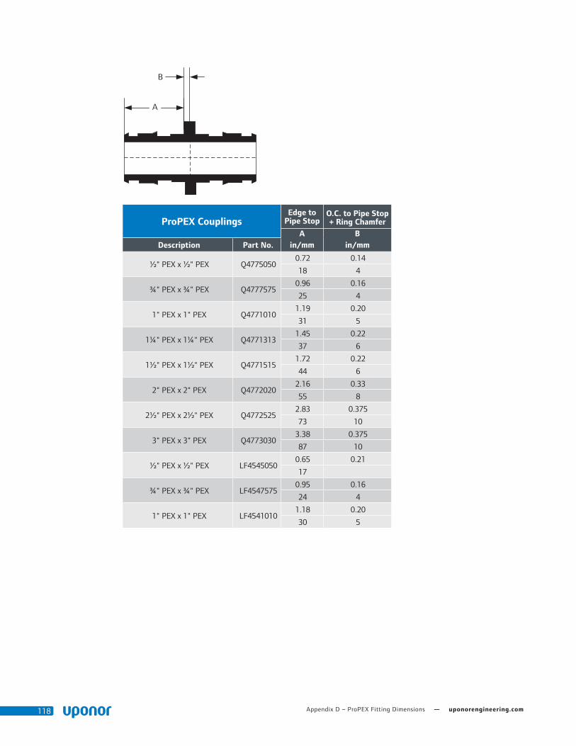
Appendix D – ProPEX Fitting Dimensions — uponorengineering.com118
ProPEX CouplingsEdge to
Pipe Stop O.C. to Pipe Stop + Ring Chamfer
A BDescription Part No. in/mm in/mm
½" PEX x ½" PEX Q47750500.72 0.14
18 4
¾" PEX x ¾" PEX Q47775750.96 0.16
25 4
1" PEX x 1" PEX Q47710101.19 0.20
31 5
1¼" PEX x 1¼" PEX Q47713131.45 0.22
37 6
1½" PEX x 1½" PEX Q47715151.72 0.22
44 6
2" PEX x 2" PEX Q47720202.16 0.33
55 8
2½" PEX x 2½" PEX Q47725252.83 0.375
73 10
3" PEX x 3" PEX Q47730303.38 0.375
87 10
½" PEX x ½" PEX LF45450500.65 0.21
17
¾" PEX x ¾" PEX LF45475750.95 0.16
24 4
1" PEX x 1" PEX LF45410101.18 0.20
30 5
A
B

Plumbing Design Assistance Manual — Appendix D – ProPEX Fitting Dimensions 119
ProPEX Reducing CouplingEdge to
Pipe Stop O.C. to Pipe Stop + Ring Chamfer
Edge to Pipe Stop
O.C. to Pipe Stop + Ring Chamfer
A B C DDescription Part No. in/mm in/mm in/mm in/mm
½" PEX x ¾" PEX Q47750750.96 0.1425 0.72 0.1625
25 2 18 4
¾" PEX x 1" PEX Q47775100.96 0.1625 1.19 0.2025
25 2 31 5
1¼" PEX x ¾" PEX Q47713070.96 0.215 1.45 0.175
25 2 37 4
1¼" PEX x 1" PEX Q47713101.20 0.215 1.45 0.215
31 2 37 6
1½" PEX x ¾" PEX Q47715070.75 0.215 1.72 0.175
19 2 44 4
1½" PEX x 1" PEX Q47715101.20 0.215 1.72 0.215
31 2 44 6
1½" PEX x 1¼" PEX Q47715131.45 0.215 1.72 0.215
37 2 44 6
2" PEX x 1½" PEX Q47720151.77 0.325 2.16 0.265
3 3 55 7
2½" PEX x 1¼" PEX Q47725132.83 0.375 1.46 0.125
37 3
2½" PEX x 1½" PEX Q47725152.83 0.375 1.72 0.125
44 3
2½" PEX x 2" PEX Q47725202.83 0.375 2.16 0.125
55 3
3" PEX x 2" PEX Q47730203.38 0.375 2.16 0.125
55 3
3" PEX x 2½" PEX Q47730253.38 0.375 2.83 0.125
73 3
¾" PEX x 1" PEX LF45475100.95 0.1625 1.16 0.2025
24 2 30 5
A
B
C
D

Appendix D – ProPEX Fitting Dimensions — uponorengineering.com120
ProPEX LF Brass Male Threaded Adapter
Edge to Pipe Stop
O.C. to Pipe Stop + Ring
A BDescription Part No. in/mm in/mm
3⁄8" PEX x ½" NPT LF45238500.591 0.205
15 5
½" PEX x ½" NPT LF45250500.748 0.195
19 5
½" PEX x ¾" NPT LF45250750.709 0.205
18 5
¾" PEX x ¾" NPT LF45275750.93 0.215
24 6
¾" PEX x 1" NPT LF45275100.945 0.225
24 6
1" PEX x ¾" NPT LF45210751.181 0.265
30
1" PEX x 1" NPT LF45210101.214 0.255
31 7
1¼" PEX x 1¼" NPT LF45213131.478 0.255
38 7
1½" PEX x 1½" NPT LF45215151.704 0.265
44 7
2" PEX x 2" NPT LF45220202.172 0.4
56 10
2½" PEX x 2½" NPT LF45225252.83 0.475
73 12
3" PEX x 3" NPT LF45230303.38 0.5
87 13
A
B

Plumbing Design Assistance Manual — Appendix D – ProPEX Fitting Dimensions 121
ProPEX LF Brass Female Threaded Adapter
Edge to Pipe Stop
O.C. to Pipe Stop + Ring
A BDescription Part No. in/mm in/mm
½" PEX x ½" NPT LF45750500.709 0.155
18 4
½" PEX x ¾" NPT LF45750750.709 0.155
18 4
¾" PEX x ¾" NPT LF45775750.945 0.175
24 4
¾" PEX x 1" NPT LF45775100.945 0.205
24 5
1" PEX x 1" NPT LF45710101.181 0.245
30 6
1¼" PEX x 1¼" NPT LF45713131.445 0.24
37 6
1½" PEX x 1½" NPT LF45715151.704 0.24
44 6
2" PEX x 2" NPT LF45720202.146 0.3
55 8
BA
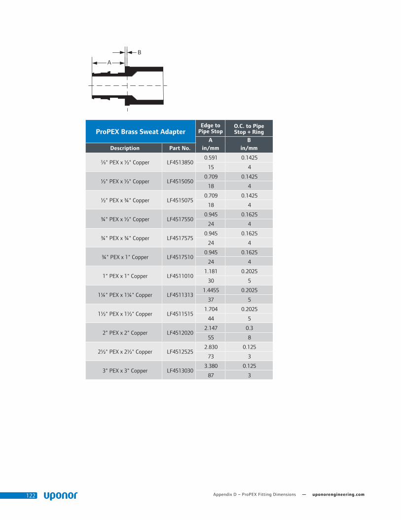
Appendix D – ProPEX Fitting Dimensions — uponorengineering.com122
ProPEX Brass Sweat AdapterEdge to
Pipe Stop O.C. to Pipe Stop + Ring
A BDescription Part No. in/mm in/mm
3⁄8" PEX x ½" Copper LF45138500.591 0.1425
15 4
½" PEX x ½" Copper LF45150500.709 0.1425
18 4
½" PEX x ¾" Copper LF45150750.709 0.1425
18 4
¾" PEX x ½" Copper LF45175500.945 0.1625
24 4
¾" PEX x ¾" Copper LF45175750.945 0.1625
24 4
¾" PEX x 1" Copper LF45175100.945 0.1625
24 4
1" PEX x 1" Copper LF45110101.181 0.2025
30 5
1¼" PEX x 1¼" Copper LF45113131.4455 0.2025
37 5
1½" PEX x 1½" Copper LF45115151.704 0.2025
44 5
2" PEX x 2" Copper LF45120202.147 0.3
55 8
2½" PEX x 2½" Copper LF45125252.830 0.125
73 3
3" PEX x 3" Copper LF45130303.380 0.125
87 3
A
B

Plumbing Design Assistance Manual — Appendix D – ProPEX Fitting Dimensions 123
ProPEX Brass Fitting AdapterEdge to
Pipe Stop O.C. to Pipe Stop + Ring
A BDescription Part No. in/mm in/mm
½" PEX x ½" Copper LF45050500.709 0.1425
18 4
½" PEX x ¾" Copper LF45050750.709 0.1425
18 4
¾" PEX x ½" Copper LF45075500.945 0.1625
24 4
¾" PEX x ¾" Copper* LF45075750.9455 0.1625
24 4
¾" PEX x 1" Copper LF45075100.9455 0.1625
24 4
1" PEX x 1" Copper* LF45010101.181 0.2025
30 5
1¼" PEX x 1¼" Copper* LF45013131.4455 0.2025
37 5
1½" PEX x 1½" Copper LF45015151.704 0.2025
44 5
2" PEX x 2" Copper* LF45020202.147 0.325
55 8
A
B
ProPEX RingDelta A & B
ADescription Part No. in/mm
½" ProPEX Ring with Stop Q4690512 0.08
¾" ProPEX Ring with Stop Q4690756 0.1
1" ProPEX Ring with Stop Q4691000 0.14
1¼" ProPEX Ring with Stop Q4691250 0.14
1½" ProPEX Ring with Stop Q4691500 0.14
2" ProPEX Ring with Stop Q4692000 0.2
2½" ProPEX Ring with Stop Q4692500 0.2
3" ProPEX Ring with Stop Q4693000 0.2
B
A

Appendix D – ProPEX Fitting Dimensions — uponorengineering.com124

Plumbing Design Assistance Manual — Appendix E – Expansion Arm and Loop Calculations 125
PEX with PEX-a Pipe Support, Strut and Strut Clamps
has a thermal expansion rate of 0.08"/10°F ΔT/100 ft. (2.03mm/5.56°C ΔT/30.48m)
Thermal Expansion in Underground Applications For direct-burial applications, mitigate the effects of thermal expansion with a proper installation that provides adequate resistance to axial stress. Per PPI TR-21 Thermal Expansion and Contraction in Plastics Piping Systems, restrain a buried or concrete-encased pipe from both lateral and axial movement with
surrounding embedment material. The magnitude of the frictional restraining force is dependent on the nature of the soil and on installation and operating conditions.
For example, the extent of compaction near the pipe can affect the quality of contact between the pipe and surrounding soil. The anchoring or restraining effect of surrounding soil on pipe movement
can be significantly augmented by external pipe geometry. Tees, lateral connections and changes in direction all help to anchor a pipe in the surrounding soil.
Appendix E
Expansion Arm and Loop Calculations
½" PEX Pipe Expansion Arm
Delta T (ΔT)
Run (ft)
Delta L (in)
Flexible Arm Length (in)
L1 (in)
L2 (in)
PEX
with P
EX-a Pipe Support, Strut and Strut C
lamps
has a thermal expansion rate of 0.08"/10°F ΔT/100 ft. (2.03m
m/5.56°C ΔT/30.48m
).
10
50 0.04 1.90 0.38 0.76
60 0.048 2.08 0.42 0.83
70 0.056 2.24 0.45 0.90
80 0.064 2.40 0.48 0.96
90 0.072 2.55 0.51 1.02
100 0.08 2.68 0.54 1.07
20
50 0.08 2.68 0.54 1.07
60 0.096 2.94 0.59 1.18
70 0.112 3.17 0.63 1.27
80 0.128 3.39 0.68 1.36
90 0.144 3.60 0.72 1.44
100 0.16 3.79 0.76 1.52
30
50 0.12 3.29 0.66 1.31
60 0.144 3.60 0.72 1.44
70 0.168 3.89 0.78 1.56
80 0.192 4.16 0.83 1.66
90 0.216 4.41 0.88 1.76
100 0.24 4.65 0.93 1.86
40
50 0.16 3.79 0.76 1.52
60 0.192 4.16 0.83 1.66
70 0.224 4.49 0.90 1.80
80 0.256 4.80 0.96 1.92
90 0.288 5.09 1.02 2.04
100 0.32 5.37 1.07 2.15
½" PEX Pipe Expansion Arm
Delta T (ΔT)
Run (ft)
Delta L (in)
Flexible Arm Length (in)
L1 (in)
L2 (in)
PEX
with P
EX-a Pipe Support, Strut and Strut C
lamps
has a thermal expansion rate of 0.08"/10°F ΔT/100 ft. (2.03m
m/5.56°C ΔT/30.48m
).
50
50 0.2 4.24 0.85 1.70
60 0.24 4.65 0.93 1.86
70 0.28 5.02 1.00 2.01
80 0.32 5.37 1.07 2.15
90 0.36 5.69 1.14 2.28
100 0.4 6.00 1.20 2.40
60
50 0.24 4.65 0.93 1.86
60 0.288 5.09 1.02 2.04
70 0.336 5.50 1.10 2.20
80 0.384 5.88 1.18 2.35
90 0.432 6.24 1.25 2.49
100 0.48 6.57 1.31 2.63
70
50 0.28 5.02 1.00 2.01
60 0.336 5.50 1.10 2.20
70 0.392 5.94 1.19 2.38
80 0.448 6.35 1.27 2.54
90 0.504 6.73 1.35 2.69
100 0.56 7.10 1.42 2.84
80
50 0.32 5.37 1.07 2.15
60 0.384 5.88 1.18 2.35
70 0.448 6.35 1.27 2.54
80 0.512 6.79 1.36 2.72
90 0.576 7.20 1.44 2.88
100 0.64 7.59 1.52 3.04
Table E-1: PEX Pipe Expansion Arm Calculations ½" to 3"

Appendix E – Expansion Arm and Loop Calculations — uponorengineering.com126
½" PEX Pipe Expansion Arm
Delta T (ΔT)
Run (ft)
Delta L (in)
Flexible Arm Length (in)
L1 (in)
L2 (in)
PEX
with P
EX-a Pipe Support, Strut and Strut C
lamps
has a thermal expansion rate of 0.08"/10°F ΔT/100 ft. (2.03m
m/5.56°C ΔT/30.48m
).
90
50 0.36 5.69 1.14 2.28
60 0.432 6.24 1.25 2.49
70 0.504 6.73 1.35 2.69
80 0.576 7.20 1.44 2.88
90 0.648 7.64 1.53 3.05
100 0.72 8.05 1.61 3.22
100
50 0.4 6.00 1.20 2.40
60 0.48 6.57 1.31 2.63
70 0.56 7.10 1.42 2.84
80 0.64 7.59 1.52 3.04
90 0.72 8.05 1.61 3.22
100 0.8 8.49 1.70 3.39
110
50 0.44 6.29 1.26 2.52
60 0.528 6.89 1.38 2.76
70 0.616 7.45 1.49 2.98
80 0.704 7.96 1.59 3.18
90 0.792 8.44 1.69 3.38
100 0.88 8.90 1.78 3.56
120
50 0.48 6.57 1.31 2.63
60 0.576 7.20 1.44 2.88
70 0.672 7.78 1.56 3.11
80 0.768 8.31 1.66 3.33
90 0.864 8.82 1.76 3.53
100 0.96 9.30 1.86 3.72
130
50 0.52 6.84 1.37 2.74
60 0.624 7.49 1.50 3.00
70 0.728 8.09 1.62 3.24
80 0.832 8.65 1.73 3.46
90 0.936 9.18 1.84 3.67
100 1.04 9.67 1.93 3.87
140
50 0.56 7.10 1.42 2.84
60 0.672 7.78 1.56 3.11
70 0.784 8.40 1.68 3.36
80 0.896 8.98 1.80 3.59
90 1.008 9.52 1.90 3.81
100 1.12 10.04 2.01 4.02
150
50 0.6 7.35 1.47 2.94
60 0.72 8.05 1.61 3.22
70 0.84 8.69 1.74 3.48
80 0.96 9.30 1.86 3.72
90 1.08 9.86 1.97 3.94
100 1.2 10.39 2.08 4.16
Table E-1: PEX Pipe Expansion Arm Calculations ½" to 3"
½" PEX Pipe Expansion Arm
Delta T (ΔT)
Run (ft)
Delta L (in)
Flexible Arm Length (in)
L1 (in)
L2 (in)
160
50 0.64 7.59 1.52 3.04
60 0.768 8.31 1.66 3.33
70 0.896 8.98 1.80 3.59
80 1.024 9.60 1.92 3.84
90 1.152 10.18 2.04 4.07
100 1.28 10.73 2.15 4.29
¾" PEX Pipe Expansion Arm
Delta T (ΔT)
Run (ft)
Delta L (in)
Flexible Arm Length (in)
L1 (in)
L2 (in)
PEX
with P
EX-a Pipe Support, Strut and Strut C
lamps
has a thermal expansion rate of 0.08"/10°F ΔT/100 ft. (2.03m
m/5.56°C ΔT/30.48m
). 10
50 0.04 2.24 0.45 0.90
60 0.048 2.46 0.49 0.98
70 0.056 2.66 0.53 1.06
80 0.064 2.84 0.57 1.14
90 0.072 3.01 0.60 1.20
100 0.08 3.17 0.63 1.27
20
50 0.08 3.17 0.63 1.27
60 0.096 3.48 0.70 1.39
70 0.112 3.76 0.75 1.50
80 0.128 4.02 0.80 1.61
90 0.144 4.26 0.85 1.70
100 0.16 4.49 0.90 1.80
30
50 0.12 3.89 0.78 1.56
60 0.144 4.26 0.85 1.70
70 0.168 4.60 0.92 1.84
80 0.192 4.92 0.98 1.97
90 0.216 5.22 1.04 2.09
100 0.24 5.50 1.10 2.20
40
50 0.16 4.49 0.90 1.80
60 0.192 4.92 0.98 1.97
70 0.224 5.31 1.06 2.13
80 0.256 5.68 1.14 2.27
90 0.288 6.02 1.20 2.41
100 0.32 6.35 1.27 2.54
50
50 0.2 5.02 1.00 2.01
60 0.24 5.50 1.10 2.20
70 0.28 5.94 1.19 2.38
80 0.32 6.35 1.27 2.54
90 0.36 6.73 1.35 2.69
100 0.4 7.10 1.42 2.84

Plumbing Design Assistance Manual — Appendix E – Expansion Arm and Loop Calculations 127
Table E-1: PEX Pipe Expansion Arm Calculations ½" to 3"
¾" PEX Pipe Expansion Arm
Delta T (ΔT)
Run (ft)
Delta L (in)
Flexible Arm Length (in)
L1 (in)
L2 (in)
PEX
with P
EX-a Pipe Support, Strut and Strut C
lamps
has a thermal expansion rate of 0.08"/10°F ΔT/100 ft. (2.03m
m/5.56°C ΔT/30.48m
).
60
50 0.24 5.50 1.10 2.20
60 0.288 6.02 1.20 2.41
70 0.336 6.51 1.30 2.60
80 0.384 6.96 1.39 2.78
90 0.432 7.38 1.48 2.95
100 0.48 7.78 1.56 3.11
70
50 0.28 5.94 1.19 2.38
60 0.336 6.51 1.30 2.60
70 0.392 7.03 1.41 2.81
80 0.448 7.51 1.50 3.01
90 0.504 7.97 1.59 3.19
100 0.56 8.40 1.68 3.36
80
50 0.32 6.35 1.27 2.54
60 0.384 6.96 1.39 2.78
70 0.448 7.51 1.50 3.01
80 0.512 8.03 1.61 3.21
90 0.576 8.52 1.70 3.41
100 0.64 8.98 1.80 3.59
90
50 0.36 6.73 1.35 2.69
60 0.432 7.38 1.48 2.95
70 0.504 7.97 1.59 3.19
80 0.576 8.52 1.70 3.41
90 0.648 9.04 1.81 3.61
100 0.72 9.52 1.90 3.81
100
50 0.4 7.10 1.42 2.84
60 0.48 7.78 1.56 3.11
70 0.56 8.40 1.68 3.36
80 0.64 8.98 1.80 3.59
90 0.72 9.52 1.90 3.81
100 0.8 10.04 2.01 4.02
110
50 0.44 7.45 1.49 2.98
60 0.528 8.16 1.63 3.26
70 0.616 8.81 1.76 3.52
80 0.704 9.42 1.88 3.77
90 0.792 9.99 2.00 4.00
100 0.88 10.53 2.11 4.21
120
50 0.48 7.78 1.56 3.11
60 0.576 8.52 1.70 3.41
70 0.672 9.20 1.84 3.68
80 0.768 9.84 1.97 3.93
90 0.864 10.43 2.09 4.17
100 0.96 11.00 2.20 4.40
¾" PEX Pipe Expansion Arm
Delta T (ΔT)
Run (ft)
Delta L (in)
Flexible Arm Length (in)
L1 (in)
L2 (in)
PEX
with P
EX-a Pipe Support, Strut and Strut C
lamps
has a thermal expansion rate of 0.08"/10°F ΔT/100 ft. (2.03m
m/5.56°C ΔT/30.48m
).
130
50 0.52 8.09 1.62 3.24
60 0.624 8.87 1.77 3.55
70 0.728 9.58 1.92 3.83
80 0.832 10.24 2.05 4.10
90 0.936 10.86 2.17 4.34
100 1.04 11.45 2.29 4.58
140
50 0.56 8.40 1.68 3.36
60 0.672 9.20 1.84 3.68
70 0.784 9.94 1.99 3.98
80 0.896 10.63 2.13 4.25
90 1.008 11.27 2.25 4.51
100 1.12 11.88 2.38 4.75
150
50 0.6 8.69 1.74 3.48
60 0.72 9.52 1.90 3.81
70 0.84 10.29 2.06 4.12
80 0.96 11.00 2.20 4.40
90 1.08 11.67 2.33 4.67
100 1.2 12.30 2.46 4.92
160
50 0.64 8.98 1.80 3.59
60 0.768 9.84 1.97 3.93
70 0.896 10.63 2.13 4.25
80 1.024 11.36 2.27 4.54
90 1.152 12.05 2.41 4.82
100 1.28 12.70 2.54 5.08
1" PEX Pipe Expansion Arm
Delta T (ΔT)
Run (ft)
Delta L (in)
Flexible Arm Length (in)
L1 (in)
L2 (in)
PEX
with P
EX-a Pipe Support, Strut
and Strut Clam
ps
10
50 0.04 2.55 0.51 1.02
60 0.048 2.79 0.56 1.12
70 0.056 3.01 0.60 1.20
80 0.064 3.22 0.64 1.29
90 0.072 3.42 0.68 1.37
100 0.08 3.60 0.72 1.44
20
50 0.08 3.60 0.72 1.44
60 0.096 3.94 0.79 1.58
70 0.112 4.26 0.85 1.70
80 0.128 4.55 0.91 1.82
90 0.144 4.83 0.97 1.93
100 0.16 5.09 1.02 2.04

Appendix E – Expansion Arm and Loop Calculations — uponorengineering.com128
Table E-1: PEX Pipe Expansion Arm Calculations ½" to 3"
1" PEX Pipe Expansion Arm
Delta T (ΔT)
Run (ft)
Delta L (in)
Flexible Arm Length (in)
L1 (in)
L2 (in)
PEX
with P
EX-a Pipe Support, Strut and Strut C
lamps
has a thermal expansion rate of 0.08"/10°F ΔT/100 ft. (2.03m
m/5.56°C ΔT/30.48m
).
30
50 0.12 4.41 0.88 1.76
60 0.144 4.83 0.97 1.93
70 0.168 5.22 1.04 2.09
80 0.192 5.58 1.12 2.23
90 0.216 5.92 1.18 2.37
100 0.24 6.24 1.25 2.49
40
50 0.16 5.09 1.02 2.04
60 0.048 2.79 0.56 1.12
70 0.056 3.01 0.60 1.20
80 0.064 3.22 0.64 1.29
90 0.072 3.42 0.68 1.37
100 0.08 3.60 0.72 1.44
50
50 0.2 5.69 1.14 2.28
60 0.24 6.24 1.25 2.49
70 0.28 6.73 1.35 2.69
80 0.32 7.20 1.44 2.88
90 0.36 7.64 1.53 3.05
100 0.4 8.05 1.61 3.22
60
50 0.24 6.24 1.25 2.49
60 0.288 6.83 1.37 2.73
70 0.336 7.38 1.48 2.95
80 0.384 7.89 1.58 3.15
90 0.432 8.37 1.67 3.35
100 0.48 8.82 1.76 3.53
70
50 0.28 6.73 1.35 2.69
60 0.336 7.38 1.48 2.95
70 0.392 7.97 1.59 3.19
80 0.448 8.52 1.70 3.41
90 0.504 9.04 1.81 3.61
100 0.56 9.52 1.90 3.81
80
50 0.32 7.20 1.44 2.88
60 0.384 7.89 1.58 3.15
70 0.448 8.52 1.70 3.41
80 0.512 9.11 1.82 3.64
90 0.576 9.66 1.93 3.86
100 0.64 10.18 2.04 4.07
90
50 0.04 2.55 0.51 1.02
60 0.048 2.79 0.56 1.12
70 0.056 3.01 0.60 1.20
80 0.064 3.22 0.64 1.29
90 0.072 3.42 0.68 1.37
100 0.08 3.60 0.72 1.44
1" PEX Pipe Expansion Arm
Delta T (ΔT)
Run (ft)
Delta L (in)
Flexible Arm Length (in)
L1 (in)
L2 (in)
PEX
with P
EX-a Pipe Support, Strut and Strut C
lamps
has a thermal expansion rate of 0.08"/10°F ΔT/100 ft. (2.03m
m/5.56°C ΔT/30.48m
).
100
50 0.08 3.60 0.72 1.44
60 0.096 3.94 0.79 1.58
70 0.112 4.26 0.85 1.70
80 0.128 4.55 0.91 1.82
90 0.144 4.83 0.97 1.93
100 0.16 5.09 1.02 2.04
110
50 0.44 8.44 1.69 3.38
60 0.528 9.25 1.85 3.70
70 0.616 9.99 2.00 4.00
80 0.704 10.68 2.14 4.27
90 0.792 11.33 2.27 4.53
100 0.88 11.94 2.39 4.78
120
50 0.48 8.82 1.76 3.53
60 0.576 9.66 1.93 3.86
70 0.672 10.43 2.09 4.17
80 0.768 11.15 2.23 4.46
90 0.864 11.83 2.37 4.73
100 0.96 12.47 2.49 4.99
130
50 0.52 9.18 1.84 3.67
60 0.624 10.05 2.01 4.02
70 0.728 10.86 2.17 4.34
80 0.832 11.61 2.32 4.64
90 0.936 12.31 2.46 4.93
100 1.04 12.98 2.60 5.19
140
50 0.56 9.52 1.90 3.81
60 0.672 10.43 2.09 4.17
70 0.784 11.27 2.25 4.51
80 0.896 12.05 2.41 4.82
90 1.008 12.78 2.56 5.11
100 1.12 13.47 2.69 5.39
150
50 0.6 9.86 1.97 3.94
60 0.72 10.80 2.16 4.32
70 0.84 11.67 2.33 4.67
80 0.96 12.47 2.49 4.99
90 1.08 13.23 2.65 5.29
100 1.2 13.94 2.79 5.58
160
50 0.64 10.18 2.04 4.07
60 0.768 11.15 2.23 4.46
70 0.896 12.05 2.41 4.82
80 1.024 12.88 2.58 5.15
90 1.152 13.66 2.73 5.46
100 1.28 14.40 2.88 5.76

Plumbing Design Assistance Manual — Appendix E – Expansion Arm and Loop Calculations 129
Table E-1: PEX Pipe Expansion Arm Calculations ½" to 3"
1¼" PEX Pipe Expansion Arm
Delta T (ΔT)
Run (ft)
Delta L (in)
Flexible Arm Length (in)
L1 (in)
L2 (in)
PEX
with P
EX-a Pipe Support, Strut and Strut C
lamps
has a thermal expansion rate of 0.08"/10°F ΔT/100 ft. (2.03m
m/5.56°C ΔT/30.48m
).
10
50 0.04 2.81 0.56 1.13
60 0.048 3.08 0.62 1.23
70 0.056 3.33 0.67 1.33
80 0.064 3.56 0.71 1.42
90 0.072 3.78 0.76 1.51
100 0.08 3.98 0.80 1.59
20
50 0.08 3.98 0.80 1.59
60 0.096 4.36 0.87 1.74
70 0.112 4.71 0.94 1.88
80 0.128 5.03 1.01 2.01
90 0.144 5.34 1.07 2.14
100 0.16 5.63 1.13 2.25
30
50 0.12 4.87 0.97 1.95
60 0.144 5.34 1.07 2.14
70 0.168 5.77 1.15 2.31
80 0.192 6.17 1.23 2.47
90 0.216 6.54 1.31 2.62
100 0.24 6.89 1.38 2.76
40
50 0.16 5.63 1.13 2.25
60 0.192 6.17 1.23 2.47
70 0.224 6.66 1.33 2.66
80 0.256 7.12 1.42 2.85
90 0.288 7.55 1.51 3.02
100 0.32 7.96 1.59 3.18
50
50 0.2 6.29 1.26 2.52
60 0.24 6.89 1.38 2.76
70 0.28 7.45 1.49 2.98
80 0.32 7.96 1.59 3.18
90 0.36 8.44 1.69 3.38
100 0.4 8.90 1.78 3.56
60
50 0.24 6.89 1.38 2.76
60 0.288 7.55 1.51 3.02
70 0.336 8.16 1.63 3.26
80 0.384 8.72 1.74 3.49
90 0.432 9.25 1.85 3.70
100 0.48 9.75 1.95 3.90
70
50 0.28 7.45 1.49 2.98
60 0.336 8.16 1.63 3.26
70 0.392 8.81 1.76 3.52
80 0.448 9.42 1.88 3.77
90 0.504 9.99 2.00 4.00
100 0.56 10.53 2.11 4.21
1¼" PEX Pipe Expansion Arm
Delta T (ΔT)
Run (ft)
Delta L (in)
Flexible Arm Length (in)
L1 (in)
L2 (in)
PEX
with P
EX-a Pipe Support, Strut and Strut C
lamps
has a thermal expansion rate of 0.08"/10°F ΔT/100 ft. (2.03m
m/5.56°C ΔT/30.48m
).
80
50 0.32 7.96 1.59 3.18
60 0.384 8.72 1.74 3.49
70 0.448 9.42 1.88 3.77
80 0.512 10.07 2.01 4.03
90 0.576 10.68 2.14 4.27
100 0.64 11.26 2.25 4.50
90
50 0.36 8.44 1.69 3.38
60 0.432 9.25 1.85 3.70
70 0.504 9.99 2.00 4.00
80 0.576 10.68 2.14 4.27
90 0.648 11.33 2.27 4.53
100 0.72 11.94 2.39 4.78
100
50 0.4 8.90 1.78 3.56
60 0.48 9.75 1.95 3.90
70 0.56 10.53 2.11 4.21
80 0.64 11.26 2.25 4.50
90 0.72 11.94 2.39 4.78
100 0.8 12.59 2.52 5.03
110
50 0.44 9.33 1.87 3.73
60 0.528 10.22 2.04 4.09
70 0.616 11.04 2.21 4.42
80 0.704 11.81 2.36 4.72
90 0.792 12.52 2.50 5.01
100 0.88 13.20 2.64 5.28
120
50 0.48 9.75 1.95 3.90
60 0.576 10.68 2.14 4.27
70 0.672 11.53 2.31 4.61
80 0.768 12.33 2.47 4.93
90 0.864 13.08 2.62 5.23
100 0.96 13.79 2.76 5.51
130
50 0.52 10.15 2.03 4.06
60 0.624 11.12 2.22 4.45
70 0.728 12.01 2.40 4.80
80 0.832 12.83 2.57 5.13
90 0.936 13.61 2.72 5.45
100 1.04 14.35 2.87 5.74
140
50 0.56 10.53 2.11 4.21
60 0.672 11.53 2.31 4.61
70 0.784 12.46 2.49 4.98
80 0.896 13.32 2.66 5.33
90 1.008 14.13 2.83 5.65
100 1.12 14.89 2.98 5.96
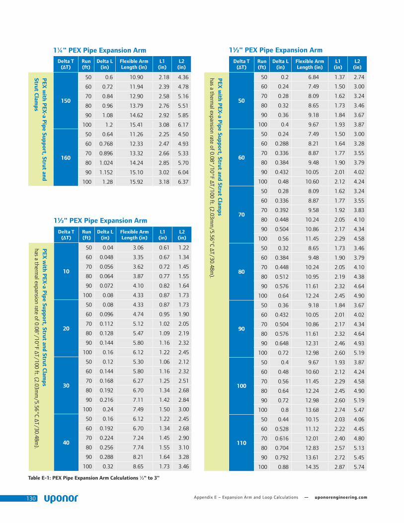
Appendix E – Expansion Arm and Loop Calculations — uponorengineering.com130
Table E-1: PEX Pipe Expansion Arm Calculations ½" to 3"
1½" PEX Pipe Expansion Arm
Delta T (ΔT)
Run (ft)
Delta L (in)
Flexible Arm Length (in)
L1 (in)
L2 (in)
PEX
with P
EX-a Pipe Support, Strut and Strut C
lamps
has a thermal expansion rate of 0.08"/10°F ΔT/100 ft. (2.03m
m/5.56°C ΔT/30.48m
).
10
50 0.04 3.06 0.61 1.22
60 0.048 3.35 0.67 1.34
70 0.056 3.62 0.72 1.45
80 0.064 3.87 0.77 1.55
90 0.072 4.10 0.82 1.64
100 0.08 4.33 0.87 1.73
20
50 0.08 4.33 0.87 1.73
60 0.096 4.74 0.95 1.90
70 0.112 5.12 1.02 2.05
80 0.128 5.47 1.09 2.19
90 0.144 5.80 1.16 2.32
100 0.16 6.12 1.22 2.45
30
50 0.12 5.30 1.06 2.12
60 0.144 5.80 1.16 2.32
70 0.168 6.27 1.25 2.51
80 0.192 6.70 1.34 2.68
90 0.216 7.11 1.42 2.84
100 0.24 7.49 1.50 3.00
40
50 0.16 6.12 1.22 2.45
60 0.192 6.70 1.34 2.68
70 0.224 7.24 1.45 2.90
80 0.256 7.74 1.55 3.10
90 0.288 8.21 1.64 3.28
100 0.32 8.65 1.73 3.46
1½" PEX Pipe Expansion Arm
Delta T (ΔT)
Run (ft)
Delta L (in)
Flexible Arm Length (in)
L1 (in)
L2 (in)
PEX
with P
EX-a Pipe Support, Strut and Strut C
lamps
has a thermal expansion rate of 0.08"/10°F ΔT/100 ft. (2.03m
m/5.56°C ΔT/30.48m
).
50
50 0.2 6.84 1.37 2.74
60 0.24 7.49 1.50 3.00
70 0.28 8.09 1.62 3.24
80 0.32 8.65 1.73 3.46
90 0.36 9.18 1.84 3.67
100 0.4 9.67 1.93 3.87
60
50 0.24 7.49 1.50 3.00
60 0.288 8.21 1.64 3.28
70 0.336 8.87 1.77 3.55
80 0.384 9.48 1.90 3.79
90 0.432 10.05 2.01 4.02
100 0.48 10.60 2.12 4.24
70
50 0.28 8.09 1.62 3.24
60 0.336 8.87 1.77 3.55
70 0.392 9.58 1.92 3.83
80 0.448 10.24 2.05 4.10
90 0.504 10.86 2.17 4.34
100 0.56 11.45 2.29 4.58
80
50 0.32 8.65 1.73 3.46
60 0.384 9.48 1.90 3.79
70 0.448 10.24 2.05 4.10
80 0.512 10.95 2.19 4.38
90 0.576 11.61 2.32 4.64
100 0.64 12.24 2.45 4.90
90
50 0.36 9.18 1.84 3.67
60 0.432 10.05 2.01 4.02
70 0.504 10.86 2.17 4.34
80 0.576 11.61 2.32 4.64
90 0.648 12.31 2.46 4.93
100 0.72 12.98 2.60 5.19
100
50 0.4 9.67 1.93 3.87
60 0.48 10.60 2.12 4.24
70 0.56 11.45 2.29 4.58
80 0.64 12.24 2.45 4.90
90 0.72 12.98 2.60 5.19
100 0.8 13.68 2.74 5.47
110
50 0.44 10.15 2.03 4.06
60 0.528 11.12 2.22 4.45
70 0.616 12.01 2.40 4.80
80 0.704 12.83 2.57 5.13
90 0.792 13.61 2.72 5.45
100 0.88 14.35 2.87 5.74
1¼" PEX Pipe Expansion Arm
Delta T (ΔT)
Run (ft)
Delta L (in)
Flexible Arm Length (in)
L1 (in)
L2 (in)
PEX
with P
EX-a Pipe Support, Strut and
Strut Clam
ps
150
50 0.6 10.90 2.18 4.36
60 0.72 11.94 2.39 4.78
70 0.84 12.90 2.58 5.16
80 0.96 13.79 2.76 5.51
90 1.08 14.62 2.92 5.85
100 1.2 15.41 3.08 6.17
160
50 0.64 11.26 2.25 4.50
60 0.768 12.33 2.47 4.93
70 0.896 13.32 2.66 5.33
80 1.024 14.24 2.85 5.70
90 1.152 15.10 3.02 6.04
100 1.28 15.92 3.18 6.37
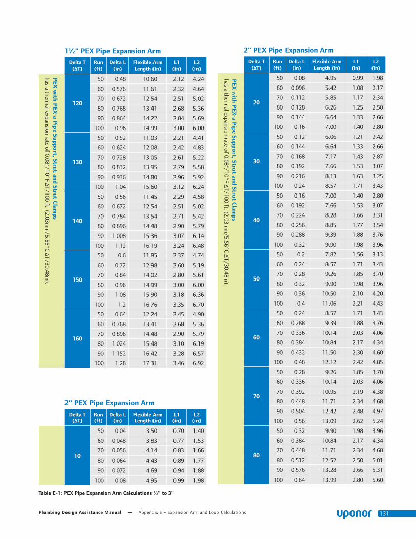
Plumbing Design Assistance Manual — Appendix E – Expansion Arm and Loop Calculations 131
1½" PEX Pipe Expansion Arm
Delta T (ΔT)
Run (ft)
Delta L (in)
Flexible Arm Length (in)
L1 (in)
L2 (in)
PEX
with P
EX-a Pipe Support, Strut and Strut C
lamps
has a thermal expansion rate of 0.08"/10°F ΔT/100 ft. (2.03m
m/5.56°C ΔT/30.48m
).
120
50 0.48 10.60 2.12 4.24
60 0.576 11.61 2.32 4.64
70 0.672 12.54 2.51 5.02
80 0.768 13.41 2.68 5.36
90 0.864 14.22 2.84 5.69
100 0.96 14.99 3.00 6.00
130
50 0.52 11.03 2.21 4.41
60 0.624 12.08 2.42 4.83
70 0.728 13.05 2.61 5.22
80 0.832 13.95 2.79 5.58
90 0.936 14.80 2.96 5.92
100 1.04 15.60 3.12 6.24
140
50 0.56 11.45 2.29 4.58
60 0.672 12.54 2.51 5.02
70 0.784 13.54 2.71 5.42
80 0.896 14.48 2.90 5.79
90 1.008 15.36 3.07 6.14
100 1.12 16.19 3.24 6.48
150
50 0.6 11.85 2.37 4.74
60 0.72 12.98 2.60 5.19
70 0.84 14.02 2.80 5.61
80 0.96 14.99 3.00 6.00
90 1.08 15.90 3.18 6.36
100 1.2 16.76 3.35 6.70
160
50 0.64 12.24 2.45 4.90
60 0.768 13.41 2.68 5.36
70 0.896 14.48 2.90 5.79
80 1.024 15.48 3.10 6.19
90 1.152 16.42 3.28 6.57
100 1.28 17.31 3.46 6.92
Table E-1: PEX Pipe Expansion Arm Calculations ½" to 3"
2" PEX Pipe Expansion Arm
Delta T (ΔT)
Run (ft)
Delta L (in)
Flexible Arm Length (in)
L1 (in)
L2 (in)
10
50 0.04 3.50 0.70 1.40
60 0.048 3.83 0.77 1.53
70 0.056 4.14 0.83 1.66
80 0.064 4.43 0.89 1.77
90 0.072 4.69 0.94 1.88
100 0.08 4.95 0.99 1.98
2" PEX Pipe Expansion Arm
Delta T (ΔT)
Run (ft)
Delta L (in)
Flexible Arm Length (in)
L1 (in)
L2 (in)
PEX
with P
EX-a Pipe Support, Strut and Strut C
lamps
has a thermal expansion rate of 0.08"/10°F ΔT/100 ft. (2.03m
m/5.56°C ΔT/30.48m
).
20
50 0.08 4.95 0.99 1.98
60 0.096 5.42 1.08 2.17
70 0.112 5.85 1.17 2.34
80 0.128 6.26 1.25 2.50
90 0.144 6.64 1.33 2.66
100 0.16 7.00 1.40 2.80
30
50 0.12 6.06 1.21 2.42
60 0.144 6.64 1.33 2.66
70 0.168 7.17 1.43 2.87
80 0.192 7.66 1.53 3.07
90 0.216 8.13 1.63 3.25
100 0.24 8.57 1.71 3.43
40
50 0.16 7.00 1.40 2.80
60 0.192 7.66 1.53 3.07
70 0.224 8.28 1.66 3.31
80 0.256 8.85 1.77 3.54
90 0.288 9.39 1.88 3.76
100 0.32 9.90 1.98 3.96
50
50 0.2 7.82 1.56 3.13
60 0.24 8.57 1.71 3.43
70 0.28 9.26 1.85 3.70
80 0.32 9.90 1.98 3.96
90 0.36 10.50 2.10 4.20
100 0.4 11.06 2.21 4.43
60
50 0.24 8.57 1.71 3.43
60 0.288 9.39 1.88 3.76
70 0.336 10.14 2.03 4.06
80 0.384 10.84 2.17 4.34
90 0.432 11.50 2.30 4.60
100 0.48 12.12 2.42 4.85
70
50 0.28 9.26 1.85 3.70
60 0.336 10.14 2.03 4.06
70 0.392 10.95 2.19 4.38
80 0.448 11.71 2.34 4.68
90 0.504 12.42 2.48 4.97
100 0.56 13.09 2.62 5.24
80
50 0.32 9.90 1.98 3.96
60 0.384 10.84 2.17 4.34
70 0.448 11.71 2.34 4.68
80 0.512 12.52 2.50 5.01
90 0.576 13.28 2.66 5.31
100 0.64 13.99 2.80 5.60

Appendix E – Expansion Arm and Loop Calculations — uponorengineering.com132
Table E-1: PEX Pipe Expansion Arm Calculations ½" to 3"
2" PEX Pipe Expansion Arm
Delta T (ΔT)
Run (ft)
Delta L (in)
Flexible Arm Length (in)
L1 (in)
L2 (in)
PEX
with P
EX-a Pipe Support, Strut and Strut C
lamps
has a thermal expansion rate of 0.08"/10°F ΔT/100 ft. (2.03m
m/5.56°C ΔT/30.48m
).
90
50 0.36 10.50 2.10 4.20
60 0.432 11.50 2.30 4.60
70 0.504 12.42 2.48 4.97
80 0.576 13.28 2.66 5.31
90 0.648 14.08 2.82 5.63
100 0.72 14.84 2.97 5.94
100
50 0.4 11.06 2.21 4.43
60 0.48 12.12 2.42 4.85
70 0.56 13.09 2.62 5.24
80 0.64 13.99 2.80 5.60
90 0.72 14.84 2.97 5.94
100 0.8 15.65 3.13 6.26
110
50 0.44 11.60 2.32 4.64
60 0.528 12.71 2.54 5.08
70 0.616 13.73 2.75 5.49
80 0.704 14.68 2.94 5.87
90 0.792 15.57 3.11 6.23
100 0.88 16.41 3.28 6.56
120
50 0.48 12.12 2.42 4.85
60 0.576 13.28 2.66 5.31
70 0.672 14.34 2.87 5.74
80 0.768 15.33 3.07 6.13
90 0.864 16.26 3.25 6.50
100 0.96 17.14 3.43 6.86
130
50 0.52 12.61 2.52 5.05
60 0.624 13.82 2.76 5.53
70 0.728 14.93 2.99 5.97
80 0.832 15.96 3.19 6.38
90 0.936 16.92 3.38 6.77
100 1.04 17.84 3.57 7.14
140
50 0.56 13.09 2.62 5.24
60 0.672 14.34 2.87 5.74
70 0.784 15.49 3.10 6.20
80 0.896 16.56 3.31 6.62
90 1.008 17.56 3.51 7.03
100 1.12 18.51 3.70 7.41
150
50 0.6 13.55 2.71 5.42
60 0.72 14.84 2.97 5.94
70 0.84 16.03 3.21 6.41
80 0.96 17.14 3.43 6.86
90 1.08 18.18 3.64 7.27
100 1.2 19.16 3.83 7.66
2" PEX Pipe Expansion Arm
Delta T (ΔT)
Run (ft)
Delta L (in)
Flexible Arm Length (in)
L1 (in)
L2 (in)
160
50 0.64 13.99 2.80 5.60
60 0.768 15.33 3.07 6.13
70 0.896 16.56 3.31 6.62
80 1.024 17.70 3.54 7.08
90 1.152 18.78 3.76 7.51
100 1.28 19.79 3.96 7.92
2½" PEX Pipe Expansion Arm
Delta T (ΔT)
Run (ft)
Delta L (in)
Flexible Arm Length (in)
L1 (in)
L2 (in)
PEX
with P
EX-a Pipe Support, Strut and Strut C
lamps
has a thermal expansion rate of 0.08"/10°F ΔT/100 ft. (2.03m
m/5.56°C ΔT/30.48m
).
10
50 0.04 3.89 0.78 1.56
60 0.048 4.26 0.85 1.70
70 0.056 4.60 0.92 1.84
80 0.064 4.92 0.98 1.97
90 0.072 5.22 1.04 2.09
100 0.08 5.50 1.10 2.20
20
50 0.08 5.50 1.10 2.20
60 0.096 6.02 1.20 2.41
70 0.112 6.51 1.30 2.60
80 0.128 6.96 1.39 2.78
90 0.144 7.38 1.48 2.95
100 0.16 7.78 1.56 3.11
30
50 0.12 6.73 1.35 2.69
60 0.144 7.38 1.48 2.95
70 0.168 7.97 1.59 3.19
80 0.192 8.52 1.70 3.41
90 0.216 9.04 1.81 3.61
100 0.24 9.52 1.90 3.81
40
50 0.16 7.78 1.56 3.11
60 0.192 8.52 1.70 3.41
70 0.224 9.20 1.84 3.68
80 0.256 9.84 1.97 3.93
90 0.288 10.43 2.09 4.17
100 0.32 11.00 2.20 4.40
50
50 0.2 8.69 1.74 3.48
60 0.24 9.52 1.90 3.81
70 0.28 10.29 2.06 4.12
80 0.32 11.00 2.20 4.40
90 0.36 11.67 2.33 4.67
100 0.4 12.30 2.46 4.92
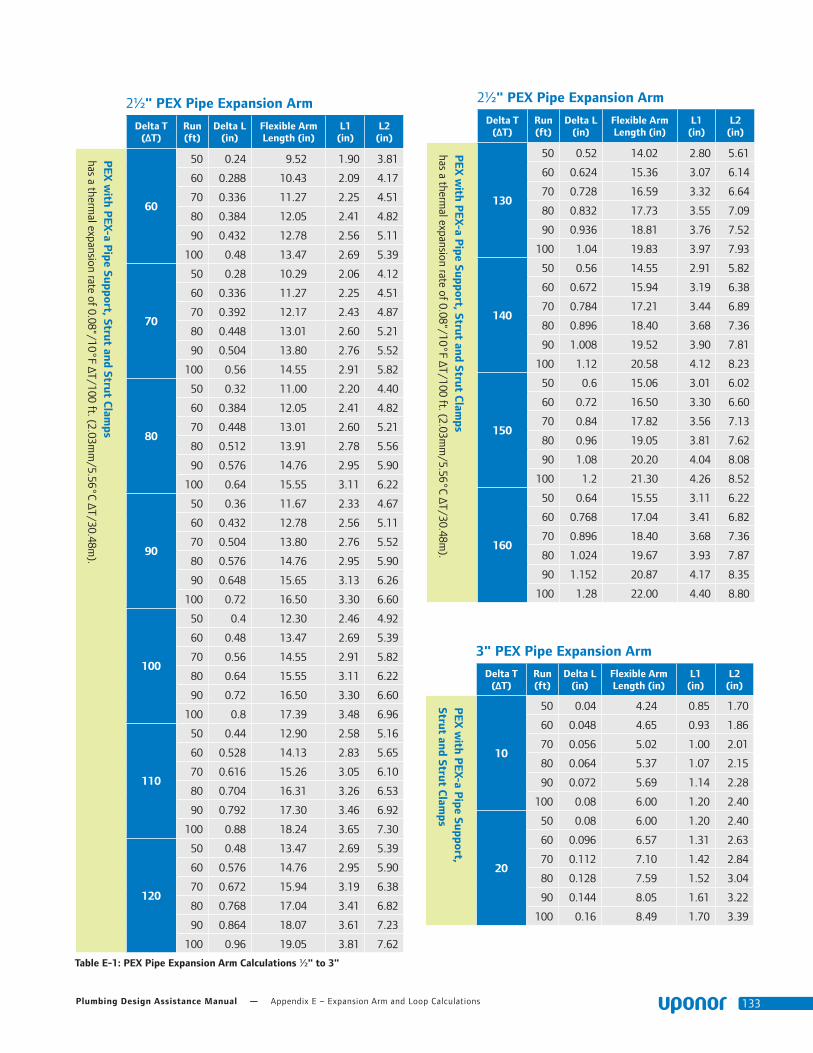
Plumbing Design Assistance Manual — Appendix E – Expansion Arm and Loop Calculations 133
Table E-1: PEX Pipe Expansion Arm Calculations ½" to 3"
2½" PEX Pipe Expansion Arm
Delta T (ΔT)
Run (ft)
Delta L (in)
Flexible Arm Length (in)
L1 (in)
L2 (in)
PEX
with P
EX-a Pipe Support, Strut and Strut C
lamps
has a thermal expansion rate of 0.08"/10°F ΔT/100 ft. (2.03m
m/5.56°C ΔT/30.48m
).
60
50 0.24 9.52 1.90 3.81
60 0.288 10.43 2.09 4.17
70 0.336 11.27 2.25 4.51
80 0.384 12.05 2.41 4.82
90 0.432 12.78 2.56 5.11
100 0.48 13.47 2.69 5.39
70
50 0.28 10.29 2.06 4.12
60 0.336 11.27 2.25 4.51
70 0.392 12.17 2.43 4.87
80 0.448 13.01 2.60 5.21
90 0.504 13.80 2.76 5.52
100 0.56 14.55 2.91 5.82
80
50 0.32 11.00 2.20 4.40
60 0.384 12.05 2.41 4.82
70 0.448 13.01 2.60 5.21
80 0.512 13.91 2.78 5.56
90 0.576 14.76 2.95 5.90
100 0.64 15.55 3.11 6.22
90
50 0.36 11.67 2.33 4.67
60 0.432 12.78 2.56 5.11
70 0.504 13.80 2.76 5.52
80 0.576 14.76 2.95 5.90
90 0.648 15.65 3.13 6.26
100 0.72 16.50 3.30 6.60
100
50 0.4 12.30 2.46 4.92
60 0.48 13.47 2.69 5.39
70 0.56 14.55 2.91 5.82
80 0.64 15.55 3.11 6.22
90 0.72 16.50 3.30 6.60
100 0.8 17.39 3.48 6.96
110
50 0.44 12.90 2.58 5.16
60 0.528 14.13 2.83 5.65
70 0.616 15.26 3.05 6.10
80 0.704 16.31 3.26 6.53
90 0.792 17.30 3.46 6.92
100 0.88 18.24 3.65 7.30
120
50 0.48 13.47 2.69 5.39
60 0.576 14.76 2.95 5.90
70 0.672 15.94 3.19 6.38
80 0.768 17.04 3.41 6.82
90 0.864 18.07 3.61 7.23
100 0.96 19.05 3.81 7.62
2½" PEX Pipe Expansion Arm
Delta T (ΔT)
Run (ft)
Delta L (in)
Flexible Arm Length (in)
L1 (in)
L2 (in)
PEX
with P
EX-a Pipe Support, Strut and Strut C
lamps
has a thermal expansion rate of 0.08"/10°F ΔT/100 ft. (2.03m
m/5.56°C ΔT/30.48m
).
130
50 0.52 14.02 2.80 5.61
60 0.624 15.36 3.07 6.14
70 0.728 16.59 3.32 6.64
80 0.832 17.73 3.55 7.09
90 0.936 18.81 3.76 7.52
100 1.04 19.83 3.97 7.93
140
50 0.56 14.55 2.91 5.82
60 0.672 15.94 3.19 6.38
70 0.784 17.21 3.44 6.89
80 0.896 18.40 3.68 7.36
90 1.008 19.52 3.90 7.81
100 1.12 20.58 4.12 8.23
150
50 0.6 15.06 3.01 6.02
60 0.72 16.50 3.30 6.60
70 0.84 17.82 3.56 7.13
80 0.96 19.05 3.81 7.62
90 1.08 20.20 4.04 8.08
100 1.2 21.30 4.26 8.52
160
50 0.64 15.55 3.11 6.22
60 0.768 17.04 3.41 6.82
70 0.896 18.40 3.68 7.36
80 1.024 19.67 3.93 7.87
90 1.152 20.87 4.17 8.35
100 1.28 22.00 4.40 8.80
3" PEX Pipe Expansion Arm
Delta T (ΔT)
Run (ft)
Delta L (in)
Flexible Arm Length (in)
L1 (in)
L2 (in)
PEX
with P
EX-a Pipe Support,
Strut and Strut Clam
ps
10
50 0.04 4.24 0.85 1.70
60 0.048 4.65 0.93 1.86
70 0.056 5.02 1.00 2.01
80 0.064 5.37 1.07 2.15
90 0.072 5.69 1.14 2.28
100 0.08 6.00 1.20 2.40
20
50 0.08 6.00 1.20 2.40
60 0.096 6.57 1.31 2.63
70 0.112 7.10 1.42 2.84
80 0.128 7.59 1.52 3.04
90 0.144 8.05 1.61 3.22
100 0.16 8.49 1.70 3.39

Appendix E – Expansion Arm and Loop Calculations — uponorengineering.com134
3" PEX Pipe Expansion Arm
Delta T (ΔT)
Run (ft)
Delta L (in)
Flexible Arm Length (in)
L1 (in)
L2 (in)
PEX
with P
EX-a Pipe Support, Strut and Strut C
lamps
has a thermal expansion rate of 0.08"/10°F ΔT/100 ft. (2.03m
m/5.56°C ΔT/30.48m
).
30
50 0.12 7.35 1.47 2.94
60 0.144 8.05 1.61 3.22
70 0.168 8.69 1.74 3.48
80 0.192 9.30 1.86 3.72
90 0.216 9.86 1.97 3.94
100 0.24 10.39 2.08 4.16
40
50 0.16 8.49 1.70 3.39
60 0.192 9.30 1.86 3.72
70 0.224 10.04 2.01 4.02
80 0.256 10.73 2.15 4.29
90 0.288 11.38 2.28 4.55
100 0.32 12.00 2.40 4.80
50
50 0.2 9.49 1.90 3.79
60 0.24 10.39 2.08 4.16
70 0.28 11.22 2.24 4.49
80 0.32 12.00 2.40 4.80
90 0.36 12.73 2.55 5.09
100 0.4 13.42 2.68 5.37
60
50 0.24 10.39 2.08 4.16
60 0.288 11.38 2.28 4.55
70 0.336 12.30 2.46 4.92
80 0.384 13.15 2.63 5.26
90 0.432 13.94 2.79 5.58
100 0.48 14.70 2.94 5.88
70
50 0.28 11.22 2.24 4.49
60 0.336 12.30 2.46 4.92
70 0.392 13.28 2.66 5.31
80 0.448 14.20 2.84 5.68
90 0.504 15.06 3.01 6.02
100 0.56 15.87 3.17 6.35
80
50 0.32 12.00 2.40 4.80
60 0.384 13.15 2.63 5.26
70 0.448 14.20 2.84 5.68
80 0.512 15.18 3.04 6.07
90 0.576 16.10 3.22 6.44
100 0.64 16.97 3.39 6.79
90
50 0.36 12.73 2.55 5.09
60 0.432 13.94 2.79 5.58
70 0.504 15.06 3.01 6.02
80 0.576 16.10 3.22 6.44
90 0.648 17.08 3.42 6.83
100 0.72 18.00 3.60 7.20
3" PEX Pipe Expansion Arm
Delta T (ΔT)
Run (ft)
Delta L (in)
Flexible Arm Length (in)
L1 (in)
L2 (in)
PEX
with P
EX-a Pipe Support, Strut and Strut C
lamps
has a thermal expansion rate of 0.08"/10°F ΔT/100 ft. (2.03m
m/5.56°C ΔT/30.48m
).
100
50 0.4 13.42 2.68 5.37
60 0.48 14.70 2.94 5.88
70 0.56 15.87 3.17 6.35
80 0.64 16.97 3.39 6.79
90 0.72 18.00 3.60 7.20
100 0.8 18.97 3.79 7.59
110
50 0.44 14.07 2.81 5.63
60 0.528 15.41 3.08 6.17
70 0.616 16.65 3.33 6.66
80 0.704 17.80 3.56 7.12
90 0.792 18.88 3.78 7.55
100 0.88 19.90 3.98 7.96
120
50 0.48 14.70 2.94 5.88
60 0.576 16.10 3.22 6.44
70 0.672 17.39 3.48 6.96
80 0.768 18.59 3.72 7.44
90 0.864 19.72 3.94 7.89
100 0.96 20.78 4.16 8.31
130
50 0.52 15.30 3.06 6.12
60 0.624 16.76 3.35 6.70
70 0.728 18.10 3.62 7.24
80 0.832 19.35 3.87 7.74
90 0.936 20.52 4.10 8.21
100 1.04 21.63 4.33 8.65
140
50 0.56 15.87 3.17 6.35
60 0.672 17.39 3.48 6.96
70 0.784 18.78 3.76 7.51
80 0.896 20.08 4.02 8.03
90 1.008 21.30 4.26 8.52
100 1.12 22.45 4.49 8.98
150
50 0.6 16.43 3.29 6.57
60 0.72 18.00 3.60 7.20
70 0.84 19.44 3.89 7.78
80 0.96 20.78 4.16 8.31
90 1.08 22.05 4.41 8.82
100 1.2 23.24 4.65 9.30
160
50 0.64 16.97 3.39 6.79
60 0.768 18.59 3.72 7.44
70 0.896 20.08 4.02 8.03
80 1.024 21.47 4.29 8.59
90 1.152 22.77 4.55 9.11
100 1.28 24.00 4.80 9.60
Table E-1: PEX Pipe Expansion Arm Calculations ½" to 3"

Plumbing Design Assistance Manual — Appendix E – Expansion Arm and Loop Calculations 135
Table E-2: PEX Pipe Expansion Arm Calculations ½" to 3"
½" PEX Pipe Expansion Arm
Delta T (ΔT)
Run (ft)
Delta L (in)
Flexible Arm Length (in)
L1 (in)
L2 (in)
PEX
with P
EX-a Pipe Support and C
levis Hangers or Loops
has a thermal expansion rate of 0.12/10°F ΔT/100 ft. (3.05m
m/5.56°C ΔT/30.48m
).
10
50 0.06 2.32 0.46 0.93
60 0.072 2.55 0.51 1.02
70 0.084 2.75 0.55 1.10
80 0.096 2.94 0.59 1.18
90 0.108 3.12 0.62 1.25
100 0.12 3.29 0.66 1.31
20
50 0.12 3.29 0.66 1.31
60 0.144 3.60 0.72 1.44
70 0.168 3.89 0.78 1.56
80 0.192 4.16 0.83 1.66
90 0.216 4.41 0.88 1.76
100 0.24 4.65 0.93 1.86
30
50 0.18 4.02 0.80 1.61
60 0.216 4.41 0.88 1.76
70 0.252 4.76 0.95 1.90
80 0.288 5.09 1.02 2.04
90 0.324 5.40 1.08 2.16
100 0.36 5.69 1.14 2.28
40
50 0.24 4.65 0.93 1.86
60 0.288 5.09 1.02 2.04
70 0.336 5.50 1.10 2.20
80 0.384 5.88 1.18 2.35
90 0.432 6.24 1.25 2.49
100 0.48 6.57 1.31 2.63
50
50 0.3 5.20 1.04 2.08
60 0.36 5.69 1.14 2.28
70 0.42 6.15 1.23 2.46
80 0.48 6.57 1.31 2.63
90 0.54 6.97 1.39 2.79
100 0.6 7.35 1.47 2.94
60
50 0.36 5.69 1.14 2.28
60 0.432 6.24 1.25 2.49
70 0.504 6.73 1.35 2.69
80 0.576 7.20 1.44 2.88
90 0.648 7.64 1.53 3.05
100 0.72 8.05 1.61 3.22
½" PEX Pipe Expansion Arm
Delta T (ΔT)
Run (ft)
Delta L (in)
Flexible Arm Length (in)
L1 (in)
L2 (in)
PEX
with P
EX-a Pipe Support and C
levis Hangers or Loops
has a thermal expansion rate of 0.12/10°F ΔT/100 ft. (3.05m
m/5.56°C ΔT/30.48m
).
70
50 0.42 6.15 1.23 2.46
60 0.504 6.73 1.35 2.69
70 0.588 7.27 1.45 2.91
80 0.672 7.78 1.56 3.11
90 0.756 8.25 1.65 3.30
100 0.84 8.69 1.74 3.48
80
50 0.48 6.57 1.31 2.63
60 0.576 7.20 1.44 2.88
70 0.672 7.78 1.56 3.11
80 0.768 8.31 1.66 3.33
90 0.864 8.82 1.76 3.53
100 0.96 9.30 1.86 3.72
90
50 0.54 6.97 1.39 2.79
60 0.648 7.64 1.53 3.05
70 0.756 8.25 1.65 3.30
80 0.864 8.82 1.76 3.53
90 0.972 9.35 1.87 3.74
100 1.08 9.86 1.97 3.94
100
50 0.6 7.35 1.47 2.94
60 0.72 8.05 1.61 3.22
70 0.84 8.69 1.74 3.48
80 0.96 9.30 1.86 3.72
90 1.08 9.86 1.97 3.94
100 1.2 10.39 2.08 4.16
110
50 0.66 7.71 1.54 3.08
60 0.792 8.44 1.69 3.38
70 0.924 9.12 1.82 3.65
80 1.056 9.75 1.95 3.90
90 1.188 10.34 2.07 4.14
100 1.32 10.90 2.18 4.36
120
50 0.72 8.05 1.61 3.22
60 0.864 8.82 1.76 3.53
70 1.008 9.52 1.90 3.81
80 1.152 10.18 2.04 4.07
90 1.296 10.80 2.16 4.32
100 1.44 11.38 2.28 4.55
PEX with PEX-a Pipe Support and Clevis Hangers or Loops
has a thermal expansion rate of 0.12/10°F ΔT/100 ft. (3.05mm/5.56°C ΔT/30.48m)

Appendix E – Expansion Arm and Loop Calculations — uponorengineering.com136
Table E-2: PEX Pipe Expansion Arm Calculations ½" to 3"
¾" PEX Pipe Expansion Arm
Delta T (ΔT)
Run (ft)
Delta L (in)
Flexible Arm Length (in)
L1 (in)
L2 (in)
PEX
with P
EX-a Pipe Support and
Clevis H
angers or Loops
10
50 0.06 2.75 0.55 1.10
60 0.072 3.01 0.60 1.20
70 0.084 3.25 0.65 1.30
80 0.096 3.48 0.70 1.39
90 0.108 3.69 0.74 1.48
100 0.12 3.89 0.78 1.56
20
50 0.12 3.89 0.78 1.56
60 0.144 4.26 0.85 1.70
70 0.168 4.60 0.92 1.84
80 0.192 4.92 0.98 1.97
90 0.216 5.22 1.04 2.09
100 0.24 5.50 1.10 2.20
½" PEX Pipe Expansion Arm
Delta T (ΔT)
Run (ft)
Delta L (in)
Flexible Arm Length (in)
L1 (in)
L2 (in)
PEX
with P
EX-a Pipe Support and C
levis Hangers or Loops
has a thermal expansion rate of 0.12/10°F ΔT/100 ft. (3.05m
m/5.56°C ΔT/30.48m
).
130
50 0.78 8.38 1.68 3.35
60 0.936 9.18 1.84 3.67
70 1.092 9.91 1.98 3.97
80 1.248 10.60 2.12 4.24
90 1.404 11.24 2.25 4.50
100 1.56 11.85 2.37 4.74
140
50 0.84 8.69 1.74 3.48
60 1.008 9.52 1.90 3.81
70 1.176 10.29 2.06 4.12
80 1.344 11.00 2.20 4.40
90 1.512 11.67 2.33 4.67
100 1.68 12.30 2.46 4.92
150
50 0.9 9.00 1.80 3.60
60 1.08 9.86 1.97 3.94
70 1.26 10.65 2.13 4.26
80 1.44 11.38 2.28 4.55
90 1.62 12.07 2.41 4.83
100 1.8 12.73 2.55 5.09
160
50 0.96 9.30 1.86 3.72
60 1.152 10.18 2.04 4.07
70 1.344 11.00 2.20 4.40
80 1.536 11.76 2.35 4.70
90 1.728 12.47 2.49 4.99
100 1.92 13.15 2.63 5.26
¾" PEX Pipe Expansion Arm
Delta T (ΔT)
Run (ft)
Delta L (in)
Flexible Arm Length (in)
L1 (in)
L2 (in)
PEX
with P
EX-a Pipe Support and C
levis Hangers or Loops
has a thermal expansion rate of 0.12/10°F ΔT/100 ft. (3.05m
m/5.56°C ΔT/30.48m
).
30
50 0.18 4.76 0.95 1.90
60 0.216 5.22 1.04 2.09
70 0.252 5.63 1.13 2.25
80 0.288 6.02 1.20 2.41
90 0.324 6.39 1.28 2.56
100 0.36 6.73 1.35 2.69
40
50 0.24 5.50 1.10 2.20
60 0.288 6.02 1.20 2.41
70 0.336 6.51 1.30 2.60
80 0.384 6.96 1.39 2.78
90 0.432 7.38 1.48 2.95
100 0.48 7.78 1.56 3.11
50
50 0.3 6.15 1.23 2.46
60 0.36 6.73 1.35 2.69
70 0.42 7.27 1.45 2.91
80 0.48 7.78 1.56 3.11
90 0.54 8.25 1.65 3.30
100 0.6 8.69 1.74 3.48
60
50 0.36 6.73 1.35 2.69
60 0.432 7.38 1.48 2.95
70 0.504 7.97 1.59 3.19
80 0.576 8.52 1.70 3.41
90 0.648 9.04 1.81 3.61
100 0.72 9.52 1.90 3.81
70
50 0.42 7.27 1.45 2.91
60 0.504 7.97 1.59 3.19
70 0.588 8.61 1.72 3.44
80 0.672 9.20 1.84 3.68
90 0.756 9.76 1.95 3.90
100 0.84 10.29 2.06 4.12
80
50 0.48 7.78 1.56 3.11
60 0.576 8.52 1.70 3.41
70 0.672 9.20 1.84 3.68
80 0.768 9.84 1.97 3.93
90 0.864 10.43 2.09 4.17
100 0.96 11.00 2.20 4.40
90
50 0.54 8.25 1.65 3.30
60 0.648 9.04 1.81 3.61
70 0.756 9.76 1.95 3.90
80 0.864 10.43 2.09 4.17
90 0.972 11.07 2.21 4.43
100 1.08 11.67 2.33 4.67

Plumbing Design Assistance Manual — Appendix E – Expansion Arm and Loop Calculations 137
¾" PEX Pipe Expansion Arm
Delta T (ΔT)
Run (ft)
Delta L (in)
Flexible Arm Length (in)
L1 (in)
L2 (in)
PEX
with P
EX-a Pipe Support and C
levis Hangers or Loops
has a thermal expansion rate of 0.12/10°F ΔT/100 ft. (3.05m
m/5.56°C ΔT/30.48m
).
100
50 0.6 8.69 1.74 3.48
60 0.72 9.52 1.90 3.81
70 0.84 10.29 2.06 4.12
80 0.96 11.00 2.20 4.40
90 1.08 11.67 2.33 4.67
100 1.2 12.30 2.46 4.92
110
50 0.66 9.12 1.82 3.65
60 0.792 9.99 2.00 4.00
70 0.924 10.79 2.16 4.32
80 1.056 11.53 2.31 4.61
90 1.188 12.23 2.45 4.89
100 1.32 12.90 2.58 5.16
120
50 0.72 9.52 1.90 3.81
60 0.864 10.43 2.09 4.17
70 1.008 11.27 2.25 4.51
80 1.152 12.05 2.41 4.82
90 1.296 12.78 2.56 5.11
100 1.44 13.47 2.69 5.39
130
50 0.78 9.91 1.98 3.97
60 0.936 10.86 2.17 4.34
70 1.092 11.73 2.35 4.69
80 1.248 12.54 2.51 5.02
90 1.404 13.30 2.66 5.32
100 1.56 14.02 2.80 5.61
140
50 0.84 10.29 2.06 4.12
60 1.008 11.27 2.25 4.51
70 1.176 12.17 2.43 4.87
80 1.344 13.01 2.60 5.21
90 1.512 13.80 2.76 5.52
100 1.68 14.55 2.91 5.82
150
50 0.9 10.65 2.13 4.26
60 1.08 11.67 2.33 4.67
70 1.26 12.60 2.52 5.04
80 1.44 13.47 2.69 5.39
90 1.62 14.29 2.86 5.71
100 1.8 15.06 3.01 6.02
160
50 0.96 11.00 2.20 4.40
60 1.152 12.05 2.41 4.82
70 1.344 13.01 2.60 5.21
80 1.536 13.91 2.78 5.56
90 1.728 14.76 2.95 5.90
100 1.92 15.55 3.11 6.22
Table E-2: PEX Pipe Expansion Arm Calculations ½" to 3"
1" PEX Pipe Expansion Arm
Delta T (ΔT)
Run (ft)
Delta L (in)
Flexible Arm Length (in)
L1 (in)
L2 (in)
PEX
with P
EX-a Pipe Support and C
levis Hangers or Loops
has a thermal expansion rate of 0.12/10°F ΔT/100 ft. (3.05m
m/5.56°C ΔT/30.48m
).
10
50 0.06 3.12 0.62 1.25
60 0.072 3.42 0.68 1.37
70 0.084 3.69 0.74 1.48
80 0.096 3.94 0.79 1.58
90 0.108 4.18 0.84 1.67
100 0.12 4.41 0.88 1.76
20
50 0.12 4.41 0.88 1.76
60 0.144 4.83 0.97 1.93
70 0.168 5.22 1.04 2.09
80 0.192 5.58 1.12 2.23
90 0.216 5.92 1.18 2.37
100 0.24 6.24 1.25 2.49
30
50 0.18 5.40 1.08 2.16
60 0.216 5.92 1.18 2.37
70 0.252 6.39 1.28 2.56
80 0.288 6.83 1.37 2.73
90 0.324 7.24 1.45 2.90
100 0.36 7.64 1.53 3.05
40
50 0.24 6.24 1.25 2.49
60 0.072 3.42 0.68 1.37
70 0.084 3.69 0.74 1.48
80 0.096 3.94 0.79 1.58
90 0.108 4.18 0.84 1.67
100 0.12 4.41 0.88 1.76
50
50 0.3 6.97 1.39 2.79
60 0.36 7.64 1.53 3.05
70 0.42 8.25 1.65 3.30
80 0.48 8.82 1.76 3.53
90 0.54 9.35 1.87 3.74
100 0.6 9.86 1.97 3.94
60
50 0.36 7.64 1.53 3.05
60 0.432 8.37 1.67 3.35
70 0.504 9.04 1.81 3.61
80 0.576 9.66 1.93 3.86
90 0.648 10.25 2.05 4.10
100 0.72 10.80 2.16 4.32
70
50 0.42 8.25 1.65 3.30
60 0.504 9.04 1.81 3.61
70 0.588 9.76 1.95 3.90
80 0.672 10.43 2.09 4.17
90 0.756 11.07 2.21 4.43
100 0.84 11.67 2.33 4.67

Appendix E – Expansion Arm and Loop Calculations — uponorengineering.com138
Table E-2: PEX Pipe Expansion Arm Calculations ½" to 3"
1¼" PEX Pipe Expansion Arm
Delta T (ΔT)
Run (ft)
Delta L (in)
Flexible Arm Length (in)
L1 (in)
L2 (in)
PEX
with P
EX-a Pipe Support and C
levis Hangers or Loops
has a thermal expansion rate of 0.12/10°F ΔT/100 ft. (3.05m
m/5.56°C ΔT/30.48m
).
10
50 0.06 3.45 0.69 1.38
60 0.072 3.78 0.76 1.51
70 0.084 4.08 0.82 1.63
80 0.096 4.36 0.87 1.74
90 0.108 4.62 0.92 1.85
100 0.12 4.87 0.97 1.95
20
50 0.12 4.87 0.97 1.95
60 0.144 5.34 1.07 2.14
70 0.168 5.77 1.15 2.31
80 0.192 6.17 1.23 2.47
90 0.216 6.54 1.31 2.62
100 0.24 6.89 1.38 2.76
30
50 0.18 5.97 1.19 2.39
60 0.216 6.54 1.31 2.62
70 0.252 7.06 1.41 2.83
80 0.288 7.55 1.51 3.02
90 0.324 8.01 1.60 3.20
100 0.36 8.44 1.69 3.38
40
50 0.24 6.89 1.38 2.76
60 0.288 7.55 1.51 3.02
70 0.336 8.16 1.63 3.26
80 0.384 8.72 1.74 3.49
90 0.432 9.25 1.85 3.70
100 0.48 9.75 1.95 3.90
1" PEX Pipe Expansion Arm
Delta T (ΔT)
Run (ft)
Delta L (in)
Flexible Arm Length (in)
L1 (in)
L2 (in)
PEX
with P
EX-a Pipe Support and C
levis Hangers or Loops
has a thermal expansion rate of 0.12/10°F ΔT/100 ft. (3.05m
m/5.56°C ΔT/30.48m
).
80
50 0.48 8.82 1.76 3.53
60 0.576 9.66 1.93 3.86
70 0.672 10.43 2.09 4.17
80 0.768 11.15 2.23 4.46
90 0.864 11.83 2.37 4.73
100 0.96 12.47 2.49 4.99
90
50 0.06 3.12 0.62 1.25
60 0.072 3.42 0.68 1.37
70 0.084 3.69 0.74 1.48
80 0.096 3.94 0.79 1.58
90 0.108 4.18 0.84 1.67
100 0.12 4.41 0.88 1.76
100
50 0.12 4.41 0.88 1.76
60 0.144 4.83 0.97 1.93
70 0.168 5.22 1.04 2.09
80 0.192 5.58 1.12 2.23
90 0.216 5.92 1.18 2.37
100 0.24 6.24 1.25 2.49
110
50 0.66 10.34 2.07 4.14
60 0.792 11.33 2.27 4.53
70 0.924 12.23 2.45 4.89
80 1.056 13.08 2.62 5.23
90 1.188 13.87 2.77 5.55
100 1.32 14.62 2.92 5.85
120
50 0.72 10.80 2.16 4.32
60 0.864 11.83 2.37 4.73
70 1.008 12.78 2.56 5.11
80 1.152 13.66 2.73 5.46
90 1.296 14.49 2.90 5.80
100 1.44 15.27 3.05 6.11
130
50 0.78 11.24 2.25 4.50
60 0.936 12.31 2.46 4.93
70 1.092 13.30 2.66 5.32
80 1.248 14.22 2.84 5.69
90 1.404 15.08 3.02 6.03
100 1.56 15.90 3.18 6.36
140
50 0.84 11.67 2.33 4.67
60 1.008 12.78 2.56 5.11
70 1.176 13.80 2.76 5.52
80 1.344 14.76 2.95 5.90
90 1.512 15.65 3.13 6.26
100 1.68 16.50 3.30 6.60
1" PEX Pipe Expansion Arm
Delta T (ΔT)
Run (ft)
Delta L (in)
Flexible Arm Length (in)
L1 (in)
L2 (in)
PEX
with P
EX-a Pipe Support and
Clevis H
angers or Loops
150
50 0.9 12.07 2.41 4.83
60 1.08 13.23 2.65 5.29
70 1.26 14.29 2.86 5.71
80 1.44 15.27 3.05 6.11
90 1.62 16.20 3.24 6.48
100 1.8 17.08 3.42 6.83
160
50 0.96 12.47 2.49 4.99
60 1.152 13.66 2.73 5.46
70 1.344 14.76 2.95 5.90
80 1.536 15.77 3.15 6.31
90 1.728 16.73 3.35 6.69
100 1.92 17.64 3.53 7.05
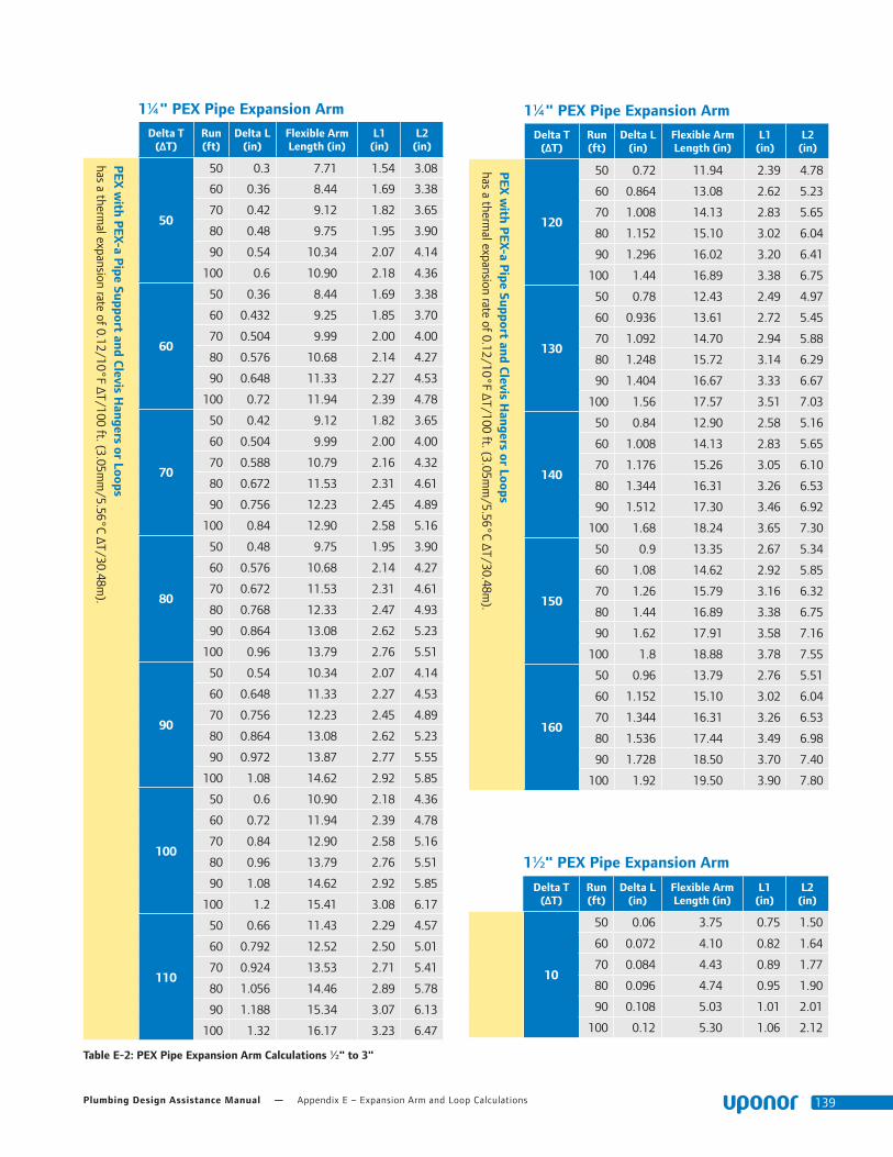
Plumbing Design Assistance Manual — Appendix E – Expansion Arm and Loop Calculations 139
Table E-2: PEX Pipe Expansion Arm Calculations ½" to 3"
1¼" PEX Pipe Expansion Arm
Delta T (ΔT)
Run (ft)
Delta L (in)
Flexible Arm Length (in)
L1 (in)
L2 (in)
PEX
with P
EX-a Pipe Support and C
levis Hangers or Loops
has a thermal expansion rate of 0.12/10°F ΔT/100 ft. (3.05m
m/5.56°C ΔT/30.48m
).
50
50 0.3 7.71 1.54 3.08
60 0.36 8.44 1.69 3.38
70 0.42 9.12 1.82 3.65
80 0.48 9.75 1.95 3.90
90 0.54 10.34 2.07 4.14
100 0.6 10.90 2.18 4.36
60
50 0.36 8.44 1.69 3.38
60 0.432 9.25 1.85 3.70
70 0.504 9.99 2.00 4.00
80 0.576 10.68 2.14 4.27
90 0.648 11.33 2.27 4.53
100 0.72 11.94 2.39 4.78
70
50 0.42 9.12 1.82 3.65
60 0.504 9.99 2.00 4.00
70 0.588 10.79 2.16 4.32
80 0.672 11.53 2.31 4.61
90 0.756 12.23 2.45 4.89
100 0.84 12.90 2.58 5.16
80
50 0.48 9.75 1.95 3.90
60 0.576 10.68 2.14 4.27
70 0.672 11.53 2.31 4.61
80 0.768 12.33 2.47 4.93
90 0.864 13.08 2.62 5.23
100 0.96 13.79 2.76 5.51
90
50 0.54 10.34 2.07 4.14
60 0.648 11.33 2.27 4.53
70 0.756 12.23 2.45 4.89
80 0.864 13.08 2.62 5.23
90 0.972 13.87 2.77 5.55
100 1.08 14.62 2.92 5.85
100
50 0.6 10.90 2.18 4.36
60 0.72 11.94 2.39 4.78
70 0.84 12.90 2.58 5.16
80 0.96 13.79 2.76 5.51
90 1.08 14.62 2.92 5.85
100 1.2 15.41 3.08 6.17
110
50 0.66 11.43 2.29 4.57
60 0.792 12.52 2.50 5.01
70 0.924 13.53 2.71 5.41
80 1.056 14.46 2.89 5.78
90 1.188 15.34 3.07 6.13
100 1.32 16.17 3.23 6.47
1¼" PEX Pipe Expansion Arm
Delta T (ΔT)
Run (ft)
Delta L (in)
Flexible Arm Length (in)
L1 (in)
L2 (in)
PEX
with P
EX-a Pipe Support and C
levis Hangers or Loops
has a thermal expansion rate of 0.12/10°F ΔT/100 ft. (3.05m
m/5.56°C ΔT/30.48m
).
120
50 0.72 11.94 2.39 4.78
60 0.864 13.08 2.62 5.23
70 1.008 14.13 2.83 5.65
80 1.152 15.10 3.02 6.04
90 1.296 16.02 3.20 6.41
100 1.44 16.89 3.38 6.75
130
50 0.78 12.43 2.49 4.97
60 0.936 13.61 2.72 5.45
70 1.092 14.70 2.94 5.88
80 1.248 15.72 3.14 6.29
90 1.404 16.67 3.33 6.67
100 1.56 17.57 3.51 7.03
140
50 0.84 12.90 2.58 5.16
60 1.008 14.13 2.83 5.65
70 1.176 15.26 3.05 6.10
80 1.344 16.31 3.26 6.53
90 1.512 17.30 3.46 6.92
100 1.68 18.24 3.65 7.30
150
50 0.9 13.35 2.67 5.34
60 1.08 14.62 2.92 5.85
70 1.26 15.79 3.16 6.32
80 1.44 16.89 3.38 6.75
90 1.62 17.91 3.58 7.16
100 1.8 18.88 3.78 7.55
160
50 0.96 13.79 2.76 5.51
60 1.152 15.10 3.02 6.04
70 1.344 16.31 3.26 6.53
80 1.536 17.44 3.49 6.98
90 1.728 18.50 3.70 7.40
100 1.92 19.50 3.90 7.80
1½" PEX Pipe Expansion Arm
Delta T (ΔT)
Run (ft)
Delta L (in)
Flexible Arm Length (in)
L1 (in)
L2 (in)
10
50 0.06 3.75 0.75 1.50
60 0.072 4.10 0.82 1.64
70 0.084 4.43 0.89 1.77
80 0.096 4.74 0.95 1.90
90 0.108 5.03 1.01 2.01
100 0.12 5.30 1.06 2.12
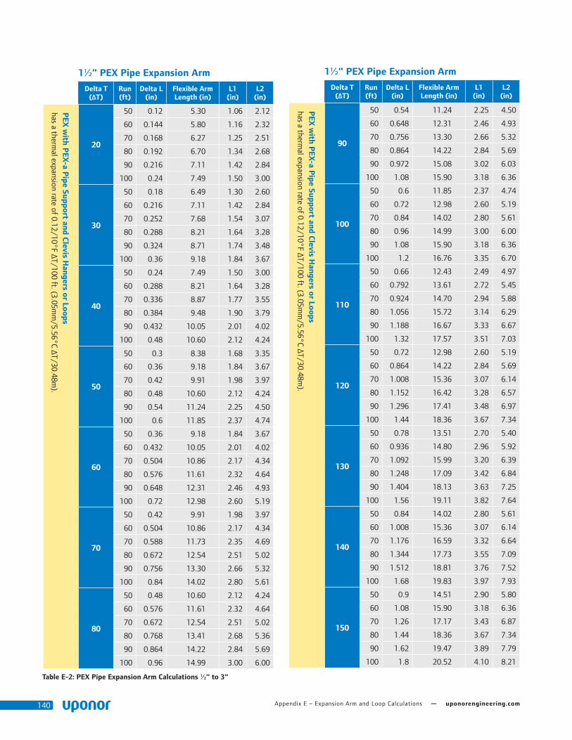
Appendix E – Expansion Arm and Loop Calculations — uponorengineering.com140
Table E-2: PEX Pipe Expansion Arm Calculations ½" to 3"
1½" PEX Pipe Expansion Arm
Delta T (ΔT)
Run (ft)
Delta L (in)
Flexible Arm Length (in)
L1 (in)
L2 (in)
PEX
with P
EX-a Pipe Support and C
levis Hangers or Loops
has a thermal expansion rate of 0.12/10°F ΔT/100 ft. (3.05m
m/5.56°C ΔT/30.48m
).
20
50 0.12 5.30 1.06 2.12
60 0.144 5.80 1.16 2.32
70 0.168 6.27 1.25 2.51
80 0.192 6.70 1.34 2.68
90 0.216 7.11 1.42 2.84
100 0.24 7.49 1.50 3.00
30
50 0.18 6.49 1.30 2.60
60 0.216 7.11 1.42 2.84
70 0.252 7.68 1.54 3.07
80 0.288 8.21 1.64 3.28
90 0.324 8.71 1.74 3.48
100 0.36 9.18 1.84 3.67
40
50 0.24 7.49 1.50 3.00
60 0.288 8.21 1.64 3.28
70 0.336 8.87 1.77 3.55
80 0.384 9.48 1.90 3.79
90 0.432 10.05 2.01 4.02
100 0.48 10.60 2.12 4.24
50
50 0.3 8.38 1.68 3.35
60 0.36 9.18 1.84 3.67
70 0.42 9.91 1.98 3.97
80 0.48 10.60 2.12 4.24
90 0.54 11.24 2.25 4.50
100 0.6 11.85 2.37 4.74
60
50 0.36 9.18 1.84 3.67
60 0.432 10.05 2.01 4.02
70 0.504 10.86 2.17 4.34
80 0.576 11.61 2.32 4.64
90 0.648 12.31 2.46 4.93
100 0.72 12.98 2.60 5.19
70
50 0.42 9.91 1.98 3.97
60 0.504 10.86 2.17 4.34
70 0.588 11.73 2.35 4.69
80 0.672 12.54 2.51 5.02
90 0.756 13.30 2.66 5.32
100 0.84 14.02 2.80 5.61
80
50 0.48 10.60 2.12 4.24
60 0.576 11.61 2.32 4.64
70 0.672 12.54 2.51 5.02
80 0.768 13.41 2.68 5.36
90 0.864 14.22 2.84 5.69
100 0.96 14.99 3.00 6.00
1½" PEX Pipe Expansion Arm
Delta T (ΔT)
Run (ft)
Delta L (in)
Flexible Arm Length (in)
L1 (in)
L2 (in)
PEX
with P
EX-a Pipe Support and C
levis Hangers or Loops
has a thermal expansion rate of 0.12/10°F ΔT/100 ft. (3.05m
m/5.56°C ΔT/30.48m
).
90
50 0.54 11.24 2.25 4.50
60 0.648 12.31 2.46 4.93
70 0.756 13.30 2.66 5.32
80 0.864 14.22 2.84 5.69
90 0.972 15.08 3.02 6.03
100 1.08 15.90 3.18 6.36
100
50 0.6 11.85 2.37 4.74
60 0.72 12.98 2.60 5.19
70 0.84 14.02 2.80 5.61
80 0.96 14.99 3.00 6.00
90 1.08 15.90 3.18 6.36
100 1.2 16.76 3.35 6.70
110
50 0.66 12.43 2.49 4.97
60 0.792 13.61 2.72 5.45
70 0.924 14.70 2.94 5.88
80 1.056 15.72 3.14 6.29
90 1.188 16.67 3.33 6.67
100 1.32 17.57 3.51 7.03
120
50 0.72 12.98 2.60 5.19
60 0.864 14.22 2.84 5.69
70 1.008 15.36 3.07 6.14
80 1.152 16.42 3.28 6.57
90 1.296 17.41 3.48 6.97
100 1.44 18.36 3.67 7.34
130
50 0.78 13.51 2.70 5.40
60 0.936 14.80 2.96 5.92
70 1.092 15.99 3.20 6.39
80 1.248 17.09 3.42 6.84
90 1.404 18.13 3.63 7.25
100 1.56 19.11 3.82 7.64
140
50 0.84 14.02 2.80 5.61
60 1.008 15.36 3.07 6.14
70 1.176 16.59 3.32 6.64
80 1.344 17.73 3.55 7.09
90 1.512 18.81 3.76 7.52
100 1.68 19.83 3.97 7.93
150
50 0.9 14.51 2.90 5.80
60 1.08 15.90 3.18 6.36
70 1.26 17.17 3.43 6.87
80 1.44 18.36 3.67 7.34
90 1.62 19.47 3.89 7.79
100 1.8 20.52 4.10 8.21

Plumbing Design Assistance Manual — Appendix E – Expansion Arm and Loop Calculations 141
Table E-2: PEX Pipe Expansion Arm Calculations ½" to 3"
2" PEX Pipe Expansion Arm
Delta T (ΔT)
Run (ft)
Delta L (in)
Flexible Arm Length (in)
L1 (in)
L2 (in)
PEX
with P
EX-a Pipe Support and C
levis Hangers or Loops
has a thermal expansion rate of 0.12/10°F ΔT/100 ft. (3.05m
m/5.56°C ΔT/30.48m
).
10
50 0.06 4.28 0.86 1.71
60 0.072 4.69 0.94 1.88
70 0.084 5.07 1.01 2.03
80 0.096 5.42 1.08 2.17
90 0.108 5.75 1.15 2.30
100 0.12 6.06 1.21 2.42
20
50 0.12 6.06 1.21 2.42
60 0.144 6.64 1.33 2.66
70 0.168 7.17 1.43 2.87
80 0.192 7.66 1.53 3.07
90 0.216 8.13 1.63 3.25
100 0.24 8.57 1.71 3.43
30
50 0.18 7.42 1.48 2.97
60 0.216 8.13 1.63 3.25
70 0.252 8.78 1.76 3.51
80 0.288 9.39 1.88 3.76
90 0.324 9.96 1.99 3.98
100 0.36 10.50 2.10 4.20
40
50 0.24 8.57 1.71 3.43
60 0.288 9.39 1.88 3.76
70 0.336 10.14 2.03 4.06
80 0.384 10.84 2.17 4.34
90 0.432 11.50 2.30 4.60
100 0.48 12.12 2.42 4.85
50
50 0.3 9.58 1.92 3.83
60 0.36 10.50 2.10 4.20
70 0.42 11.34 2.27 4.53
80 0.48 12.12 2.42 4.85
90 0.54 12.85 2.57 5.14
100 0.6 13.55 2.71 5.42
1½" PEX Pipe Expansion Arm
Delta T (ΔT)
Run (ft)
Delta L (in)
Flexible Arm Length (in)
L1 (in)
L2 (in)
160
50 0.96 14.99 3.00 6.00
60 1.152 16.42 3.28 6.57
70 1.344 17.73 3.55 7.09
80 1.536 18.96 3.79 7.58
90 1.728 20.11 4.02 8.04
100 1.92 21.20 4.24 8.48
2" PEX Pipe Expansion Arm
Delta T (ΔT)
Run (ft)
Delta L (in)
Flexible Arm Length (in)
L1 (in)
L2 (in)
PEX
with P
EX-a Pipe Support and C
levis Hangers or Loops
has a thermal expansion rate of 0.12/10°F ΔT/100 ft. (3.05m
m/5.56°C ΔT/30.48m
).
60
50 0.36 10.50 2.10 4.20
60 0.432 11.50 2.30 4.60
70 0.504 12.42 2.48 4.97
80 0.576 13.28 2.66 5.31
90 0.648 14.08 2.82 5.63
100 0.72 14.84 2.97 5.94
70
50 0.42 11.34 2.27 4.53
60 0.504 12.42 2.48 4.97
70 0.588 13.41 2.68 5.37
80 0.672 14.34 2.87 5.74
90 0.756 15.21 3.04 6.08
100 0.84 16.03 3.21 6.41
80
50 0.48 12.12 2.42 4.85
60 0.576 13.28 2.66 5.31
70 0.672 14.34 2.87 5.74
80 0.768 15.33 3.07 6.13
90 0.864 16.26 3.25 6.50
100 0.96 17.14 3.43 6.86
90
50 0.54 12.85 2.57 5.14
60 0.648 14.08 2.82 5.63
70 0.756 15.21 3.04 6.08
80 0.864 16.26 3.25 6.50
90 0.972 17.25 3.45 6.90
100 1.08 18.18 3.64 7.27
100
50 0.6 13.55 2.71 5.42
60 0.72 14.84 2.97 5.94
70 0.84 16.03 3.21 6.41
80 0.96 17.14 3.43 6.86
90 1.08 18.18 3.64 7.27
100 1.2 19.16 3.83 7.66
110
50 0.66 14.21 2.84 5.68
60 0.792 15.57 3.11 6.23
70 0.924 16.81 3.36 6.73
80 1.056 17.98 3.60 7.19
90 1.188 19.07 3.81 7.63
100 1.32 20.10 4.02 8.04
120
50 0.72 14.84 2.97 5.94
60 0.864 16.26 3.25 6.50
70 1.008 17.56 3.51 7.03
80 1.152 18.78 3.76 7.51
90 1.296 19.91 3.98 7.97
100 1.44 20.99 4.20 8.40
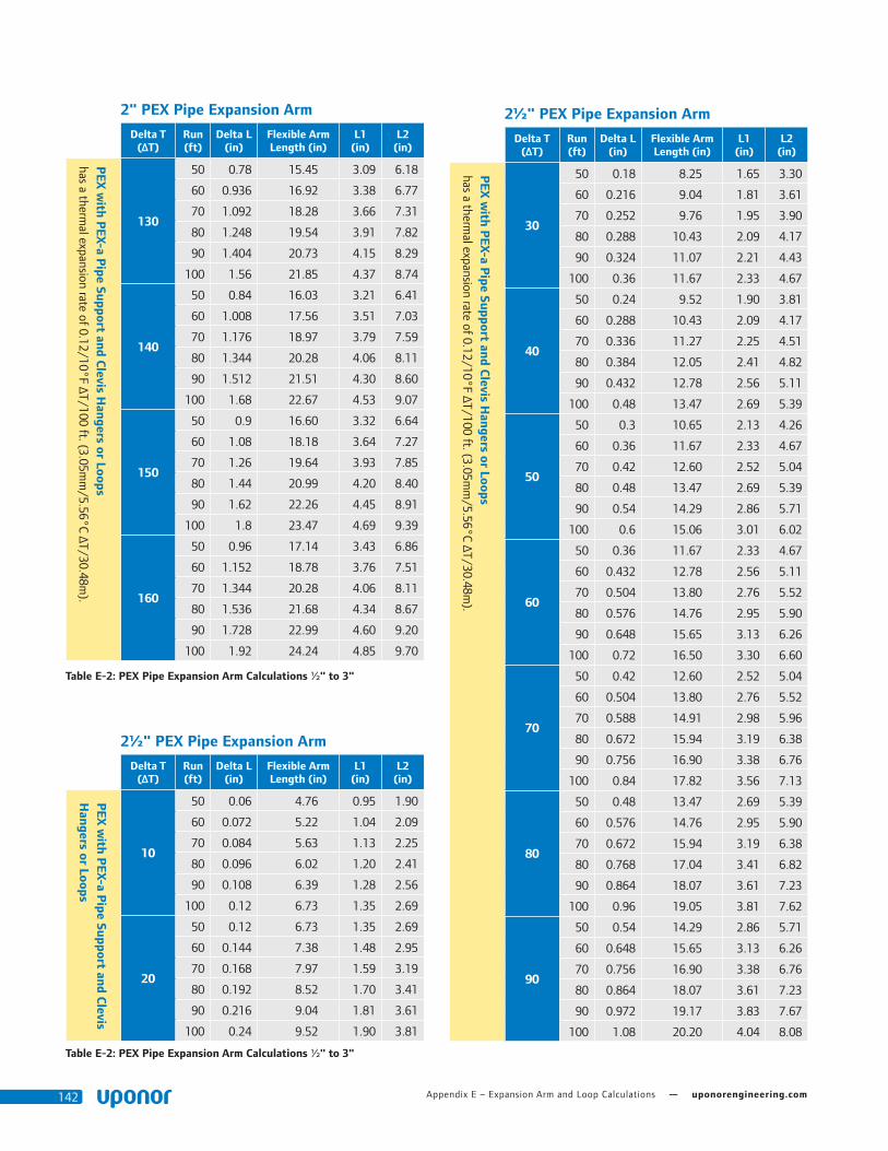
Appendix E – Expansion Arm and Loop Calculations — uponorengineering.com142
Table E-2: PEX Pipe Expansion Arm Calculations ½" to 3"
2" PEX Pipe Expansion Arm
Delta T (ΔT)
Run (ft)
Delta L (in)
Flexible Arm Length (in)
L1 (in)
L2 (in)
PEX
with P
EX-a Pipe Support and C
levis Hangers or Loops
has a thermal expansion rate of 0.12/10°F ΔT/100 ft. (3.05m
m/5.56°C ΔT/30.48m
).
130
50 0.78 15.45 3.09 6.18
60 0.936 16.92 3.38 6.77
70 1.092 18.28 3.66 7.31
80 1.248 19.54 3.91 7.82
90 1.404 20.73 4.15 8.29
100 1.56 21.85 4.37 8.74
140
50 0.84 16.03 3.21 6.41
60 1.008 17.56 3.51 7.03
70 1.176 18.97 3.79 7.59
80 1.344 20.28 4.06 8.11
90 1.512 21.51 4.30 8.60
100 1.68 22.67 4.53 9.07
150
50 0.9 16.60 3.32 6.64
60 1.08 18.18 3.64 7.27
70 1.26 19.64 3.93 7.85
80 1.44 20.99 4.20 8.40
90 1.62 22.26 4.45 8.91
100 1.8 23.47 4.69 9.39
160
50 0.96 17.14 3.43 6.86
60 1.152 18.78 3.76 7.51
70 1.344 20.28 4.06 8.11
80 1.536 21.68 4.34 8.67
90 1.728 22.99 4.60 9.20
100 1.92 24.24 4.85 9.70
2½" PEX Pipe Expansion Arm
Delta T (ΔT)
Run (ft)
Delta L (in)
Flexible Arm Length (in)
L1 (in)
L2 (in)
PEX
with P
EX-a Pipe Support and C
levis H
angers or Loops
10
50 0.06 4.76 0.95 1.90
60 0.072 5.22 1.04 2.09
70 0.084 5.63 1.13 2.25
80 0.096 6.02 1.20 2.41
90 0.108 6.39 1.28 2.56
100 0.12 6.73 1.35 2.69
20
50 0.12 6.73 1.35 2.69
60 0.144 7.38 1.48 2.95
70 0.168 7.97 1.59 3.19
80 0.192 8.52 1.70 3.41
90 0.216 9.04 1.81 3.61
100 0.24 9.52 1.90 3.81
2½" PEX Pipe Expansion Arm
Delta T (ΔT)
Run (ft)
Delta L (in)
Flexible Arm Length (in)
L1 (in)
L2 (in)
PEX
with P
EX-a Pipe Support and C
levis Hangers or Loops
has a thermal expansion rate of 0.12/10°F ΔT/100 ft. (3.05m
m/5.56°C ΔT/30.48m
).
30
50 0.18 8.25 1.65 3.30
60 0.216 9.04 1.81 3.61
70 0.252 9.76 1.95 3.90
80 0.288 10.43 2.09 4.17
90 0.324 11.07 2.21 4.43
100 0.36 11.67 2.33 4.67
40
50 0.24 9.52 1.90 3.81
60 0.288 10.43 2.09 4.17
70 0.336 11.27 2.25 4.51
80 0.384 12.05 2.41 4.82
90 0.432 12.78 2.56 5.11
100 0.48 13.47 2.69 5.39
50
50 0.3 10.65 2.13 4.26
60 0.36 11.67 2.33 4.67
70 0.42 12.60 2.52 5.04
80 0.48 13.47 2.69 5.39
90 0.54 14.29 2.86 5.71
100 0.6 15.06 3.01 6.02
60
50 0.36 11.67 2.33 4.67
60 0.432 12.78 2.56 5.11
70 0.504 13.80 2.76 5.52
80 0.576 14.76 2.95 5.90
90 0.648 15.65 3.13 6.26
100 0.72 16.50 3.30 6.60
70
50 0.42 12.60 2.52 5.04
60 0.504 13.80 2.76 5.52
70 0.588 14.91 2.98 5.96
80 0.672 15.94 3.19 6.38
90 0.756 16.90 3.38 6.76
100 0.84 17.82 3.56 7.13
80
50 0.48 13.47 2.69 5.39
60 0.576 14.76 2.95 5.90
70 0.672 15.94 3.19 6.38
80 0.768 17.04 3.41 6.82
90 0.864 18.07 3.61 7.23
100 0.96 19.05 3.81 7.62
90
50 0.54 14.29 2.86 5.71
60 0.648 15.65 3.13 6.26
70 0.756 16.90 3.38 6.76
80 0.864 18.07 3.61 7.23
90 0.972 19.17 3.83 7.67
100 1.08 20.20 4.04 8.08
Table E-2: PEX Pipe Expansion Arm Calculations ½" to 3"
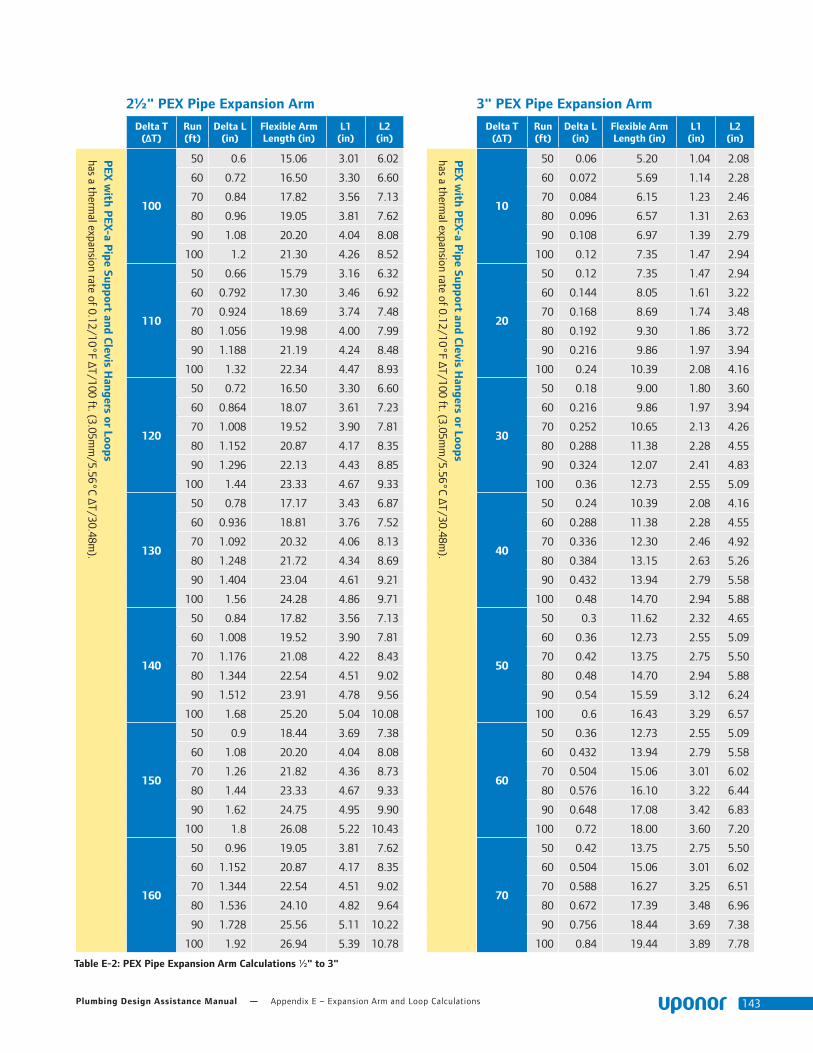
Plumbing Design Assistance Manual — Appendix E – Expansion Arm and Loop Calculations 143
2½" PEX Pipe Expansion Arm
Delta T (ΔT)
Run (ft)
Delta L (in)
Flexible Arm Length (in)
L1 (in)
L2 (in)
PEX
with P
EX-a Pipe Support and C
levis Hangers or Loops
has a thermal expansion rate of 0.12/10°F ΔT/100 ft. (3.05m
m/5.56°C ΔT/30.48m
).
100
50 0.6 15.06 3.01 6.02
60 0.72 16.50 3.30 6.60
70 0.84 17.82 3.56 7.13
80 0.96 19.05 3.81 7.62
90 1.08 20.20 4.04 8.08
100 1.2 21.30 4.26 8.52
110
50 0.66 15.79 3.16 6.32
60 0.792 17.30 3.46 6.92
70 0.924 18.69 3.74 7.48
80 1.056 19.98 4.00 7.99
90 1.188 21.19 4.24 8.48
100 1.32 22.34 4.47 8.93
120
50 0.72 16.50 3.30 6.60
60 0.864 18.07 3.61 7.23
70 1.008 19.52 3.90 7.81
80 1.152 20.87 4.17 8.35
90 1.296 22.13 4.43 8.85
100 1.44 23.33 4.67 9.33
130
50 0.78 17.17 3.43 6.87
60 0.936 18.81 3.76 7.52
70 1.092 20.32 4.06 8.13
80 1.248 21.72 4.34 8.69
90 1.404 23.04 4.61 9.21
100 1.56 24.28 4.86 9.71
140
50 0.84 17.82 3.56 7.13
60 1.008 19.52 3.90 7.81
70 1.176 21.08 4.22 8.43
80 1.344 22.54 4.51 9.02
90 1.512 23.91 4.78 9.56
100 1.68 25.20 5.04 10.08
150
50 0.9 18.44 3.69 7.38
60 1.08 20.20 4.04 8.08
70 1.26 21.82 4.36 8.73
80 1.44 23.33 4.67 9.33
90 1.62 24.75 4.95 9.90
100 1.8 26.08 5.22 10.43
160
50 0.96 19.05 3.81 7.62
60 1.152 20.87 4.17 8.35
70 1.344 22.54 4.51 9.02
80 1.536 24.10 4.82 9.64
90 1.728 25.56 5.11 10.22
100 1.92 26.94 5.39 10.78
3" PEX Pipe Expansion Arm
Delta T (ΔT)
Run (ft)
Delta L (in)
Flexible Arm Length (in)
L1 (in)
L2 (in)
PEX
with P
EX-a Pipe Support and C
levis Hangers or Loops
has a thermal expansion rate of 0.12/10°F ΔT/100 ft. (3.05m
m/5.56°C ΔT/30.48m
).
10
50 0.06 5.20 1.04 2.08
60 0.072 5.69 1.14 2.28
70 0.084 6.15 1.23 2.46
80 0.096 6.57 1.31 2.63
90 0.108 6.97 1.39 2.79
100 0.12 7.35 1.47 2.94
20
50 0.12 7.35 1.47 2.94
60 0.144 8.05 1.61 3.22
70 0.168 8.69 1.74 3.48
80 0.192 9.30 1.86 3.72
90 0.216 9.86 1.97 3.94
100 0.24 10.39 2.08 4.16
30
50 0.18 9.00 1.80 3.60
60 0.216 9.86 1.97 3.94
70 0.252 10.65 2.13 4.26
80 0.288 11.38 2.28 4.55
90 0.324 12.07 2.41 4.83
100 0.36 12.73 2.55 5.09
40
50 0.24 10.39 2.08 4.16
60 0.288 11.38 2.28 4.55
70 0.336 12.30 2.46 4.92
80 0.384 13.15 2.63 5.26
90 0.432 13.94 2.79 5.58
100 0.48 14.70 2.94 5.88
50
50 0.3 11.62 2.32 4.65
60 0.36 12.73 2.55 5.09
70 0.42 13.75 2.75 5.50
80 0.48 14.70 2.94 5.88
90 0.54 15.59 3.12 6.24
100 0.6 16.43 3.29 6.57
60
50 0.36 12.73 2.55 5.09
60 0.432 13.94 2.79 5.58
70 0.504 15.06 3.01 6.02
80 0.576 16.10 3.22 6.44
90 0.648 17.08 3.42 6.83
100 0.72 18.00 3.60 7.20
70
50 0.42 13.75 2.75 5.50
60 0.504 15.06 3.01 6.02
70 0.588 16.27 3.25 6.51
80 0.672 17.39 3.48 6.96
90 0.756 18.44 3.69 7.38
100 0.84 19.44 3.89 7.78
Table E-2: PEX Pipe Expansion Arm Calculations ½" to 3"

Appendix E – Expansion Arm and Loop Calculations — uponorengineering.com144
3" PEX Pipe Expansion Arm
Delta T (ΔT)
Run (ft)
Delta L (in)
Flexible Arm Length (in)
L1 (in)
L2 (in)
PEX
with P
EX-a Pipe Support and C
levis Hangers or Loops
has a thermal expansion rate of 0.12/10°F ΔT/100 ft. (3.05m
m/5.56°C ΔT/30.48m
).
80
50 0.48 14.70 2.94 5.88
60 0.576 16.10 3.22 6.44
70 0.672 17.39 3.48 6.96
80 0.768 18.59 3.72 7.44
90 0.864 19.72 3.94 7.89
100 0.96 20.78 4.16 8.31
90
50 0.54 15.59 3.12 6.24
60 0.648 17.08 3.42 6.83
70 0.756 18.44 3.69 7.38
80 0.864 19.72 3.94 7.89
90 0.972 20.91 4.18 8.37
100 1.08 22.05 4.41 8.82
100
50 0.6 16.43 3.29 6.57
60 0.72 18.00 3.60 7.20
70 0.84 19.44 3.89 7.78
80 0.96 20.78 4.16 8.31
90 1.08 22.05 4.41 8.82
100 1.2 23.24 4.65 9.30
110
50 0.66 17.23 3.45 6.89
60 0.792 18.88 3.78 7.55
70 0.924 20.39 4.08 8.16
80 1.056 21.80 4.36 8.72
90 1.188 23.12 4.62 9.25
100 1.32 24.37 4.87 9.75
120
50 0.72 18.00 3.60 7.20
60 0.864 19.72 3.94 7.89
70 1.008 21.30 4.26 8.52
80 1.152 22.77 4.55 9.11
90 1.296 24.15 4.83 9.66
100 1.44 25.46 5.09 10.18
130
50 0.78 18.73 3.75 7.49
60 0.936 20.52 4.10 8.21
70 1.092 22.17 4.43 8.87
80 1.248 23.70 4.74 9.48
90 1.404 25.14 5.03 10.05
100 1.56 26.50 5.30 10.60
140
50 0.84 19.44 3.89 7.78
60 1.008 21.30 4.26 8.52
70 1.176 23.00 4.60 9.20
80 1.344 24.59 4.92 9.84
90 1.512 26.08 5.22 10.43
100 1.68 27.50 5.50 11.00
3" PEX Pipe Expansion Arm
Delta T (ΔT)
Run (ft)
Delta L (in)
Flexible Arm Length (in)
L1 (in)
L2 (in)
PEX
with P
EX-a Pipe Support and C
levis H
angers or Loops
150
50 0.9 20.12 4.02 8.05
60 1.08 22.05 4.41 8.82
70 1.26 23.81 4.76 9.52
80 1.44 25.46 5.09 10.18
90 1.62 27.00 5.40 10.80
100 1.8 28.46 5.69 11.38
160
50 0.96 20.78 4.16 8.31
60 1.152 22.77 4.55 9.11
70 1.344 24.59 4.92 9.84
80 1.536 26.29 5.26 10.52
90 1.728 27.89 5.58 11.15
100 1.92 29.39 5.88 11.76
Table E-2: PEX Pipe Expansion Arm Calculations ½" to 3"

Plumbing Design Assistance Manual — Appendix E – Expansion Arm and Loop Calculations 145
½" PEX Pipe Expansion Arm
Delta T (ΔT)
Run (ft)
Delta L (in)
Flexible Arm Length (in)
L1 (in)
L2 (in)
PEX
has a Free-body thermal expansion rate of
1.1"/10°F ΔT/100 ft. (27.94mm
/5.56°C ΔT/30.48m).
10
50 0.55 7.04 1.41 2.81
60 0.66 7.71 1.54 3.08
70 0.77 8.32 1.66 3.33
80 0.88 8.90 1.78 3.56
90 0.99 9.44 1.89 3.78
100 1.1 9.95 1.99 3.98
20
50 1.1 9.95 1.99 3.98
60 1.32 10.90 2.18 4.36
70 1.54 11.77 2.35 4.71
80 1.76 12.59 2.52 5.03
90 1.98 13.35 2.67 5.34
100 2.2 14.07 2.81 5.63
30
50 1.65 12.19 2.44 4.87
60 1.98 13.35 2.67 5.34
70 2.31 14.42 2.88 5.77
80 2.64 15.41 3.08 6.17
90 2.97 16.35 3.27 6.54
100 3.3 17.23 3.45 6.89
40
50 2.2 14.07 2.81 5.63
60 2.64 15.41 3.08 6.17
70 3.08 16.65 3.33 6.66
80 3.52 17.80 3.56 7.12
90 3.96 18.88 3.78 7.55
100 4.4 19.90 3.98 7.96
50
50 2.75 15.73 3.15 6.29
60 3.3 17.23 3.45 6.89
70 3.85 18.61 3.72 7.45
80 4.4 19.90 3.98 7.96
90 4.95 21.11 4.22 8.44
100 5.5 22.25 4.45 8.90
60
50 3.3 17.23 3.45 6.89
60 3.96 18.88 3.78 7.55
70 4.62 20.39 4.08 8.16
80 5.28 21.80 4.36 8.72
90 5.94 23.12 4.62 9.25
100 6.6 24.37 4.87 9.75
½" PEX Pipe Expansion Arm
Delta T (ΔT)
Run (ft)
Delta L (in)
Flexible Arm Length (in)
L1 (in)
L2 (in)
PEX
has a Free-body thermal expansion rate of
1.1"/10°F ΔT/100 ft. (27.94mm
/5.56°C ΔT/30.48m).
70
50 3.85 18.61 3.72 7.45
60 4.62 20.39 4.08 8.16
70 5.39 22.02 4.40 8.81
80 6.16 23.55 4.71 9.42
90 6.93 24.97 4.99 9.99
100 7.7 26.32 5.26 10.53
80
50 4.4 19.90 3.98 7.96
60 5.28 21.80 4.36 8.72
70 6.16 23.55 4.71 9.42
80 7.04 25.17 5.03 10.07
90 7.92 26.70 5.34 10.68
100 8.8 28.14 5.63 11.26
90
50 4.95 21.11 4.22 8.44
60 5.94 23.12 4.62 9.25
70 6.93 24.97 4.99 9.99
80 7.92 26.70 5.34 10.68
90 8.91 28.32 5.66 11.33
100 9.9 29.85 5.97 11.94
100
50 5.5 22.25 4.45 8.90
60 6.6 24.37 4.87 9.75
70 7.7 26.32 5.26 10.53
80 8.8 28.14 5.63 11.26
90 9.9 29.85 5.97 11.94
100 11 31.46 6.29 12.59
110
50 6.05 23.33 4.67 9.33
60 7.26 25.56 5.11 10.22
70 8.47 27.61 5.52 11.04
80 9.68 29.52 5.90 11.81
90 10.89 31.31 6.26 12.52
100 12.1 33.00 6.60 13.20
120
50 6.6 24.37 4.87 9.75
60 7.92 26.70 5.34 10.68
70 9.24 28.84 5.77 11.53
80 10.56 30.83 6.17 12.33
90 11.88 32.70 6.54 13.08
100 13.2 34.47 6.89 13.79
Table E-3: PEX Pipe Expansion Arm Calculations ½" to 3"
PEX has a Free-body
thermal expansion rate of 1.1"/10°F ΔT/100 ft. (27.94mm/5.56°C ΔT/30.48m)

Appendix E – Expansion Arm and Loop Calculations — uponorengineering.com146
Table E-3: PEX Pipe Expansion Arm Calculations ½" to 3"
Table E-3: PEX Pipe Expansion Arm Calculations ½" to 3"
¾" PEX Pipe Expansion Arm
Delta T (ΔT)
Run (ft)
Delta L (in)
Flexible Arm Length (in)
L1 (in)
L2 (in)
PEX
has a Free-body thermal expansion rate of
1.1"/10°F ΔT/100 ft. (27.94mm
/5.56°C ΔT/30.48m).
30
50 1.65 14.42 2.88 5.77
60 1.98 15.79 3.16 6.32
70 2.31 17.06 3.41 6.82
80 2.64 18.24 3.65 7.30
90 2.97 19.34 3.87 7.74
100 3.3 20.39 4.08 8.16
40
50 2.2 16.65 3.33 6.66
60 2.64 18.24 3.65 7.30
70 3.08 19.70 3.94 7.88
80 3.52 21.06 4.21 8.42
90 3.96 22.34 4.47 8.93
100 4.4 23.55 4.71 9.42
50
50 2.75 18.61 3.72 7.45
60 3.3 20.39 4.08 8.16
70 3.85 22.02 4.40 8.81
80 4.4 23.55 4.71 9.42
90 4.95 24.97 4.99 9.99
100 5.5 26.32 5.26 10.53
60
50 3.3 20.39 4.08 8.16
60 3.96 22.34 4.47 8.93
70 4.62 24.13 4.83 9.65
80 5.28 25.79 5.16 10.32
90 5.94 27.36 5.47 10.94
100 6.6 28.84 5.77 11.53
70
50 3.85 22.02 4.40 8.81
60 4.62 24.13 4.83 9.65
70 5.39 26.06 5.21 10.42
80 6.16 27.86 5.57 11.14
90 6.93 29.55 5.91 11.82
100 7.7 31.15 6.23 12.46
80
50 4.4 23.55 4.71 9.42
60 5.28 25.79 5.16 10.32
70 6.16 27.86 5.57 11.14
80 7.04 29.78 5.96 11.91
90 7.92 31.59 6.32 12.64
100 8.8 33.30 6.66 13.32
90
50 4.95 24.97 4.99 9.99
60 5.94 27.36 5.47 10.94
70 6.93 29.55 5.91 11.82
80 7.92 31.59 6.32 12.64
90 8.91 33.51 6.70 13.40
100 9.9 35.32 7.06 14.13
½" PEX Pipe Expansion Arm
Delta T (ΔT)
Run (ft)
Delta L (in)
Flexible Arm Length (in)
L1 (in)
L2 (in)
PEX
has a Free-body thermal expansion rate of
1.1"/10°F ΔT/100 ft. (27.94mm
/5.56°C ΔT/30.48m).
130
50 7.15 25.37 5.07 10.15
60 8.58 27.79 5.56 11.12
70 10.01 30.01 6.00 12.01
80 11.44 32.09 6.42 12.83
90 12.87 34.03 6.81 13.61
100 14.3 35.87 7.17 14.35
140
50 7.7 26.32 5.26 10.53
60 9.24 28.84 5.77 11.53
70 10.78 31.15 6.23 12.46
80 12.32 33.30 6.66 13.32
90 13.86 35.32 7.06 14.13
100 15.4 37.23 7.45 14.89
150
50 8.25 27.25 5.45 10.90
60 9.9 29.85 5.97 11.94
70 11.55 32.24 6.45 12.90
80 13.2 34.47 6.89 13.79
90 14.85 36.56 7.31 14.62
100 16.5 38.54 7.71 15.41
160
50 8.8 28.14 5.63 11.26
60 10.56 30.83 6.17 12.33
70 12.32 33.30 6.66 13.32
80 14.08 35.60 7.12 14.24
90 15.84 37.76 7.55 15.10
100 17.6 39.80 7.96 15.92
¾" PEX Pipe Expansion Arm
Delta T (ΔT)
Run (ft)
Delta L (in)
Flexible Arm Length (in)
L1 (in)
L2 (in)
10
50 0.55 8.32 1.66 3.33
60 0.66 9.12 1.82 3.65
70 0.77 9.85 1.97 3.94
80 0.88 10.53 2.11 4.21
90 0.99 11.17 2.23 4.47
100 1.1 11.77 2.35 4.71
20
50 1.1 11.77 2.35 4.71
60 1.32 12.90 2.58 5.16
70 1.54 13.93 2.79 5.57
80 1.76 14.89 2.98 5.96
90 1.98 15.79 3.16 6.32
100 2.2 16.65 3.33 6.66
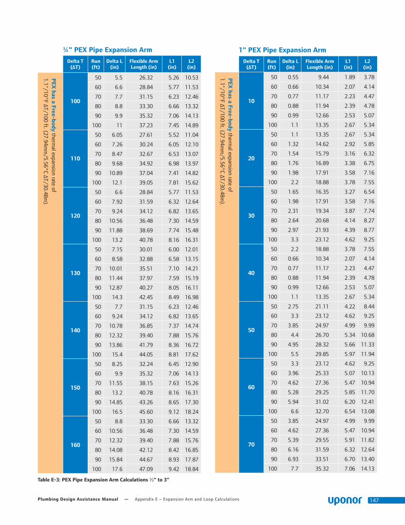
Plumbing Design Assistance Manual — Appendix E – Expansion Arm and Loop Calculations 147
Table E-3: PEX Pipe Expansion Arm Calculations ½" to 3"
¾" PEX Pipe Expansion Arm
Delta T (ΔT)
Run (ft)
Delta L (in)
Flexible Arm Length (in)
L1 (in)
L2 (in)
PEX
has a Free-body thermal expansion rate of
1.1"/10°F ΔT/100 ft. (27.94mm
/5.56°C ΔT/30.48m).
100
50 5.5 26.32 5.26 10.53
60 6.6 28.84 5.77 11.53
70 7.7 31.15 6.23 12.46
80 8.8 33.30 6.66 13.32
90 9.9 35.32 7.06 14.13
100 11 37.23 7.45 14.89
110
50 6.05 27.61 5.52 11.04
60 7.26 30.24 6.05 12.10
70 8.47 32.67 6.53 13.07
80 9.68 34.92 6.98 13.97
90 10.89 37.04 7.41 14.82
100 12.1 39.05 7.81 15.62
120
50 6.6 28.84 5.77 11.53
60 7.92 31.59 6.32 12.64
70 9.24 34.12 6.82 13.65
80 10.56 36.48 7.30 14.59
90 11.88 38.69 7.74 15.48
100 13.2 40.78 8.16 16.31
130
50 7.15 30.01 6.00 12.01
60 8.58 32.88 6.58 13.15
70 10.01 35.51 7.10 14.21
80 11.44 37.97 7.59 15.19
90 12.87 40.27 8.05 16.11
100 14.3 42.45 8.49 16.98
140
50 7.7 31.15 6.23 12.46
60 9.24 34.12 6.82 13.65
70 10.78 36.85 7.37 14.74
80 12.32 39.40 7.88 15.76
90 13.86 41.79 8.36 16.72
100 15.4 44.05 8.81 17.62
150
50 8.25 32.24 6.45 12.90
60 9.9 35.32 7.06 14.13
70 11.55 38.15 7.63 15.26
80 13.2 40.78 8.16 16.31
90 14.85 43.26 8.65 17.30
100 16.5 45.60 9.12 18.24
160
50 8.8 33.30 6.66 13.32
60 10.56 36.48 7.30 14.59
70 12.32 39.40 7.88 15.76
80 14.08 42.12 8.42 16.85
90 15.84 44.67 8.93 17.87
100 17.6 47.09 9.42 18.84
1" PEX Pipe Expansion Arm
Delta T (ΔT)
Run (ft)
Delta L (in)
Flexible Arm Length (in)
L1 (in)
L2 (in)
PEX
has a Free-body thermal expansion rate of
1.1"/10°F ΔT/100 ft. (27.94mm
/5.56°C ΔT/30.48m).
10
50 0.55 9.44 1.89 3.78
60 0.66 10.34 2.07 4.14
70 0.77 11.17 2.23 4.47
80 0.88 11.94 2.39 4.78
90 0.99 12.66 2.53 5.07
100 1.1 13.35 2.67 5.34
20
50 1.1 13.35 2.67 5.34
60 1.32 14.62 2.92 5.85
70 1.54 15.79 3.16 6.32
80 1.76 16.89 3.38 6.75
90 1.98 17.91 3.58 7.16
100 2.2 18.88 3.78 7.55
30
50 1.65 16.35 3.27 6.54
60 1.98 17.91 3.58 7.16
70 2.31 19.34 3.87 7.74
80 2.64 20.68 4.14 8.27
90 2.97 21.93 4.39 8.77
100 3.3 23.12 4.62 9.25
40
50 2.2 18.88 3.78 7.55
60 0.66 10.34 2.07 4.14
70 0.77 11.17 2.23 4.47
80 0.88 11.94 2.39 4.78
90 0.99 12.66 2.53 5.07
100 1.1 13.35 2.67 5.34
50
50 2.75 21.11 4.22 8.44
60 3.3 23.12 4.62 9.25
70 3.85 24.97 4.99 9.99
80 4.4 26.70 5.34 10.68
90 4.95 28.32 5.66 11.33
100 5.5 29.85 5.97 11.94
60
50 3.3 23.12 4.62 9.25
60 3.96 25.33 5.07 10.13
70 4.62 27.36 5.47 10.94
80 5.28 29.25 5.85 11.70
90 5.94 31.02 6.20 12.41
100 6.6 32.70 6.54 13.08
70
50 3.85 24.97 4.99 9.99
60 4.62 27.36 5.47 10.94
70 5.39 29.55 5.91 11.82
80 6.16 31.59 6.32 12.64
90 6.93 33.51 6.70 13.40
100 7.7 35.32 7.06 14.13

Appendix E – Expansion Arm and Loop Calculations — uponorengineering.com148
Table E-3: PEX Pipe Expansion Arm Calculations ½" to 3"
1" PEX Pipe Expansion Arm
Delta T (ΔT)
Run (ft)
Delta L (in)
Flexible Arm Length (in)
L1 (in)
L2 (in)
PEX
has a Free-body thermal expansion rate of
1.1"/10°F ΔT/100 ft. (27.94mm
/5.56°C ΔT/30.48m).
80
50 4.4 26.70 5.34 10.68
60 5.28 29.25 5.85 11.70
70 6.16 31.59 6.32 12.64
80 7.04 33.77 6.75 13.51
90 7.92 35.82 7.16 14.33
100 8.8 37.76 7.55 15.10
90
50 0.55 9.44 1.89 3.78
60 0.66 10.34 2.07 4.14
70 0.77 11.17 2.23 4.47
80 0.88 11.94 2.39 4.78
90 0.99 12.66 2.53 5.07
100 1.1 13.35 2.67 5.34
100
50 1.1 13.35 2.67 5.34
60 1.32 14.62 2.92 5.85
70 1.54 15.79 3.16 6.32
80 1.76 16.89 3.38 6.75
90 1.98 17.91 3.58 7.16
100 2.2 18.88 3.78 7.55
110
50 6.05 31.31 6.26 12.52
60 7.26 34.29 6.86 13.72
70 8.47 37.04 7.41 14.82
80 9.68 39.60 7.92 15.84
90 10.89 42.00 8.40 16.80
100 12.1 44.27 8.85 17.71
120
50 6.6 32.70 6.54 13.08
60 7.92 35.82 7.16 14.33
70 9.24 38.69 7.74 15.48
80 10.56 41.36 8.27 16.54
90 11.88 43.87 8.77 17.55
100 13.2 46.24 9.25 18.50
130
50 7.15 34.03 6.81 13.61
60 8.58 37.28 7.46 14.91
70 10.01 40.27 8.05 16.11
80 11.44 43.05 8.61 17.22
90 12.87 45.66 9.13 18.26
100 14.3 48.13 9.63 19.25
140
50 7.7 35.32 7.06 14.13
60 9.24 38.69 7.74 15.48
70 10.78 41.79 8.36 16.72
80 12.32 44.67 8.93 17.87
90 13.86 47.38 9.48 18.95
100 15.4 49.95 9.99 19.98
1" PEX Pipe Expansion Arm
Delta T (ΔT)
Run (ft)
Delta L (in)
Flexible Arm Length (in)
L1 (in)
L2 (in)
150
50 8.25 36.56 7.31 14.62
60 9.9 40.05 8.01 16.02
70 11.55 43.26 8.65 17.30
80 13.2 46.24 9.25 18.50
90 14.85 49.05 9.81 19.62
100 16.5 51.70 10.34 20.68
160
50 8.8 37.76 7.55 15.10
60 10.56 41.36 8.27 16.54
70 12.32 44.67 8.93 17.87
80 14.08 47.76 9.55 19.10
90 15.84 50.66 10.13 20.26
100 17.6 53.40 10.68 21.36
1¼" PEX Pipe Expansion Arm
Delta T (ΔT)
Run (ft)
Delta L (in)
Flexible Arm Length (in)
L1 (in)
L2 (in)
PEX
has a Free-body thermal expansion rate of
1.1"/10°F ΔT/100 ft. (27.94mm
/5.56°C ΔT/30.48m).
10
50 0.55 10.44 2.09 4.17
60 0.66 11.43 2.29 4.57
70 0.77 12.35 2.47 4.94
80 0.88 13.20 2.64 5.28
90 0.99 14.00 2.80 5.60
100 1.1 14.76 2.95 5.90
20
50 0.55 10.44 2.09 4.17
60 0.66 11.43 2.29 4.57
70 0.77 12.35 2.47 4.94
80 0.88 13.20 2.64 5.28
90 0.99 14.00 2.80 5.60
100 1.1 14.76 2.95 5.90
30
50 1.1 14.76 2.95 5.90
60 1.32 16.17 3.23 6.47
70 1.54 17.46 3.49 6.98
80 1.76 18.67 3.73 7.47
90 1.98 19.80 3.96 7.92
100 2.2 20.87 4.17 8.35
40
50 1.65 18.07 3.61 7.23
60 1.98 19.80 3.96 7.92
70 2.31 21.39 4.28 8.55
80 2.64 22.86 4.57 9.15
90 2.97 24.25 4.85 9.70
100 3.3 25.56 5.11 10.22
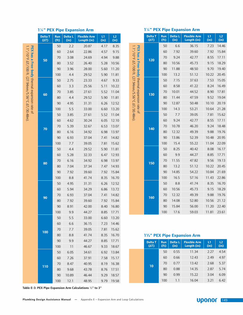
Plumbing Design Assistance Manual — Appendix E – Expansion Arm and Loop Calculations 149
Table E-3: PEX Pipe Expansion Arm Calculations ½" to 3"
1¼" PEX Pipe Expansion Arm
Delta T (ΔT)
Run (ft)
Delta L (in)
Flexible Arm Length (in)
L1 (in)
L2 (in)
PEX
has a Free-body thermal expansion rate of
1.1"/10°F ΔT/100 ft. (27.94mm
/5.56°C ΔT/30.48m).
50
50 2.2 20.87 4.17 8.35
60 2.64 22.86 4.57 9.15
70 3.08 24.69 4.94 9.88
80 3.52 26.40 5.28 10.56
90 3.96 28.00 5.60 11.20
100 4.4 29.52 5.90 11.81
60
50 2.75 23.33 4.67 9.33
60 3.3 25.56 5.11 10.22
70 3.85 27.61 5.52 11.04
80 4.4 29.52 5.90 11.81
90 4.95 31.31 6.26 12.52
100 5.5 33.00 6.60 13.20
70
50 3.85 27.61 5.52 11.04
60 4.62 30.24 6.05 12.10
70 5.39 32.67 6.53 13.07
80 6.16 34.92 6.98 13.97
90 6.93 37.04 7.41 14.82
100 7.7 39.05 7.81 15.62
80
50 4.4 29.52 5.90 11.81
60 5.28 32.33 6.47 12.93
70 6.16 34.92 6.98 13.97
80 7.04 37.34 7.47 14.93
90 7.92 39.60 7.92 15.84
100 8.8 41.74 8.35 16.70
90
50 4.95 31.31 6.26 12.52
60 5.94 34.29 6.86 13.72
70 6.93 37.04 7.41 14.82
80 7.92 39.60 7.92 15.84
90 8.91 42.00 8.40 16.80
100 9.9 44.27 8.85 17.71
100
50 5.5 33.00 6.60 13.20
60 6.6 36.15 7.23 14.46
70 7.7 39.05 7.81 15.62
80 8.8 41.74 8.35 16.70
90 9.9 44.27 8.85 17.71
100 11 46.67 9.33 18.67
110
50 6.05 34.61 6.92 13.84
60 7.26 37.91 7.58 15.17
70 8.47 40.95 8.19 16.38
80 9.68 43.78 8.76 17.51
90 10.89 46.44 9.29 18.57
100 12.1 48.95 9.79 19.58
1¼" PEX Pipe Expansion Arm
Delta T (ΔT)
Run (ft)
Delta L (in)
Flexible Arm Length (in)
L1 (in)
L2 (in)
PEX
has a Free-body thermal expansion rate of
1.1"/10°F ΔT/100 ft. (27.94mm
/5.56°C ΔT/30.48m).
120
50 6.6 36.15 7.23 14.46
60 7.92 39.60 7.92 15.84
70 9.24 42.77 8.55 17.11
80 10.56 45.73 9.15 18.29
90 11.88 48.50 9.70 19.40
100 13.2 51.12 10.22 20.45
130
50 7.15 37.63 7.53 15.05
60 8.58 41.22 8.24 16.49
70 10.01 44.52 8.90 17.81
80 11.44 47.59 9.52 19.04
90 12.87 50.48 10.10 20.19
100 14.3 53.21 10.64 21.28
140
50 7.7 39.05 7.81 15.62
60 9.24 42.77 8.55 17.11
70 10.78 46.20 9.24 18.48
80 12.32 49.39 9.88 19.76
90 13.86 52.39 10.48 20.95
100 15.4 55.22 11.04 22.09
150
50 8.25 40.42 8.08 16.17
60 9.9 44.27 8.85 17.71
70 11.55 47.82 9.56 19.13
80 13.2 51.12 10.22 20.45
90 14.85 54.22 10.84 21.69
100 16.5 57.16 11.43 22.86
160
50 8.8 41.74 8.35 16.70
60 10.56 45.73 9.15 18.29
70 12.32 49.39 9.88 19.76
80 14.08 52.80 10.56 21.12
90 15.84 56.00 11.20 22.40
100 17.6 59.03 11.81 23.61
1½" PEX Pipe Expansion Arm
Delta T (ΔT)
Run (ft)
Delta L (in)
Flexible Arm Length (in)
L1 (in)
L2 (in)
10
50 0.55 11.34 2.27 4.54
60 0.66 12.43 2.49 4.97
70 0.77 13.42 2.68 5.37
80 0.88 14.35 2.87 5.74
90 0.99 15.22 3.04 6.09
100 1.1 16.04 3.21 6.42

Appendix E – Expansion Arm and Loop Calculations — uponorengineering.com150
Table E-3: PEX Pipe Expansion Arm Calculations ½" to 3"
1½" PEX Pipe Expansion Arm
Delta T (ΔT)
Run (ft)
Delta L (in)
Flexible Arm Length (in)
L1 (in)
L2 (in)
PEX
has a Free-body thermal expansion rate of
1.1"/10°F ΔT/100 ft. (27.94mm
/5.56°C ΔT/30.48m).
20
50 1.1 16.04 3.21 6.42
60 1.32 17.57 3.51 7.03
70 1.54 18.98 3.80 7.59
80 1.76 20.29 4.06 8.12
90 1.98 21.52 4.30 8.61
100 2.2 22.69 4.54 9.08
30
50 1.65 19.65 3.93 7.86
60 1.98 21.52 4.30 8.61
70 2.31 23.25 4.65 9.30
80 2.64 24.85 4.97 9.94
90 2.97 26.36 5.27 10.54
100 3.3 27.79 5.56 11.12
40
50 2.2 22.69 4.54 9.08
60 2.64 24.85 4.97 9.94
70 3.08 26.85 5.37 10.74
80 3.52 28.70 5.74 11.48
90 3.96 30.44 6.09 12.18
100 4.4 32.09 6.42 12.83
50
50 2.75 25.37 5.07 10.15
60 3.3 27.79 5.56 11.12
70 3.85 30.01 6.00 12.01
80 4.4 32.09 6.42 12.83
90 4.95 34.03 6.81 13.61
100 5.5 35.87 7.17 14.35
60
50 3.3 27.79 5.56 11.12
60 3.96 30.44 6.09 12.18
70 4.62 32.88 6.58 13.15
80 5.28 35.15 7.03 14.06
90 5.94 37.28 7.46 14.91
100 6.6 39.30 7.86 15.72
70
50 3.85 30.01 6.00 12.01
60 4.62 32.88 6.58 13.15
70 5.39 35.51 7.10 14.21
80 6.16 37.97 7.59 15.19
90 6.93 40.27 8.05 16.11
100 7.7 42.45 8.49 16.98
80
50 4.4 32.09 6.42 12.83
60 5.28 35.15 7.03 14.06
70 6.16 37.97 7.59 15.19
80 7.04 40.59 8.12 16.24
90 7.92 43.05 8.61 17.22
100 8.8 45.38 9.08 18.15
1½" PEX Pipe Expansion Arm
Delta T (ΔT)
Run (ft)
Delta L (in)
Flexible Arm Length (in)
L1 (in)
L2 (in)
PEX
has a Free-body thermal expansion rate of
1.1"/10°F ΔT/100 ft. (27.94mm
/5.56°C ΔT/30.48m).
90
50 4.95 34.03 6.81 13.61
60 5.94 37.28 7.46 14.91
70 6.93 40.27 8.05 16.11
80 7.92 43.05 8.61 17.22
90 8.91 45.66 9.13 18.26
100 9.9 48.13 9.63 19.25
100
50 5.5 35.87 7.17 14.35
60 6.6 39.30 7.86 15.72
70 7.7 42.45 8.49 16.98
80 8.8 45.38 9.08 18.15
90 9.9 48.13 9.63 19.25
100 11 50.73 10.15 20.29
110
50 6.05 37.63 7.53 15.05
60 7.26 41.22 8.24 16.49
70 8.47 44.52 8.90 17.81
80 9.68 47.59 9.52 19.04
90 10.89 50.48 10.10 20.19
100 12.1 53.21 10.64 21.28
120
50 6.6 39.30 7.86 15.72
60 7.92 43.05 8.61 17.22
70 9.24 46.50 9.30 18.60
80 10.56 49.71 9.94 19.88
90 11.88 52.72 10.54 21.09
100 13.2 55.58 11.12 22.23
130
50 7.15 40.90 8.18 16.36
60 8.58 44.81 8.96 17.92
70 10.01 48.40 9.68 19.36
80 11.44 51.74 10.35 20.70
90 12.87 54.88 10.98 21.95
100 14.3 57.85 11.57 23.14
140
50 7.7 42.45 8.49 16.98
60 9.24 46.50 9.30 18.60
70 10.78 50.22 10.04 20.09
80 12.32 53.69 10.74 21.48
90 13.86 56.95 11.39 22.78
100 15.4 60.03 12.01 24.01
150
50 8.25 43.94 8.79 17.57
60 9.9 48.13 9.63 19.25
70 11.55 51.99 10.40 20.79
80 13.2 55.58 11.12 22.23
90 14.85 58.95 11.79 23.58
100 16.5 62.14 12.43 24.85

Plumbing Design Assistance Manual — Appendix E – Expansion Arm and Loop Calculations 151
1½" PEX Pipe Expansion Arm
Delta T (ΔT)
Run (ft)
Delta L (in)
Flexible Arm Length (in)
L1 (in)
L2 (in)
160
50 8.8 45.38 9.08 18.15
60 10.56 49.71 9.94 19.88
70 12.32 53.69 10.74 21.48
80 14.08 57.40 11.48 22.96
90 15.84 60.88 12.18 24.35
100 17.6 64.17 12.83 25.67
Table E-3: PEX Pipe Expansion Arm Calculations ½" to 3"
2" PEX Pipe Expansion Arm
Delta T (ΔT)
Run (ft)
Delta L (in)
Flexible Arm Length (in)
L1 (in)
L2 (in)
PEX
has a Free-body thermal expansion rate of
1.1"/10°F ΔT/100 ft. (27.94mm
/5.56°C ΔT/30.48m).
10
50 0.55 12.97 2.59 5.19
60 0.66 14.21 2.84 5.68
70 0.77 15.35 3.07 6.14
80 0.88 16.41 3.28 6.56
90 0.99 17.41 3.48 6.96
100 1.1 18.35 3.67 7.34
20
50 1.1 18.35 3.67 7.34
60 1.32 20.10 4.02 8.04
70 1.54 21.71 4.34 8.68
80 1.76 23.21 4.64 9.28
90 1.98 24.61 4.92 9.85
100 2.2 25.95 5.19 10.38
30
50 1.65 22.47 4.49 8.99
60 1.98 24.61 4.92 9.85
70 2.31 26.59 5.32 10.63
80 2.64 28.42 5.68 11.37
90 2.97 30.15 6.03 12.06
100 3.3 31.78 6.36 12.71
40
50 2.2 25.95 5.19 10.38
60 2.64 28.42 5.68 11.37
70 3.08 30.70 6.14 12.28
80 3.52 32.82 6.56 13.13
90 3.96 34.81 6.96 13.92
100 4.4 36.69 7.34 14.68
50
50 2.75 29.01 5.80 11.60
60 3.3 31.78 6.36 12.71
70 3.85 34.32 6.86 13.73
80 4.4 36.69 7.34 14.68
90 4.95 38.92 7.78 15.57
100 5.5 41.02 8.20 16.41
2" PEX Pipe Expansion Arm
Delta T (ΔT)
Run (ft)
Delta L (in)
Flexible Arm Length (in)
L1 (in)
L2 (in)
PEX
has a Free-body thermal expansion rate of
1.1"/10°F ΔT/100 ft. (27.94mm
/5.56°C ΔT/30.48m).
60
50 3.3 31.78 6.36 12.71
60 3.96 34.81 6.96 13.92
70 4.62 37.60 7.52 15.04
80 5.28 40.20 8.04 16.08
90 5.94 42.63 8.53 17.05
100 6.6 44.94 8.99 17.98
70
50 3.85 34.32 6.86 13.73
60 4.62 37.60 7.52 15.04
70 5.39 40.61 8.12 16.24
80 6.16 43.42 8.68 17.37
90 6.93 46.05 9.21 18.42
100 7.7 48.54 9.71 19.42
80
50 4.4 36.69 7.34 14.68
60 5.28 40.20 8.04 16.08
70 6.16 43.42 8.68 17.37
80 7.04 46.41 9.28 18.57
90 7.92 49.23 9.85 19.69
100 8.8 51.89 10.38 20.76
90
50 4.95 38.92 7.78 15.57
60 5.94 42.63 8.53 17.05
70 6.93 46.05 9.21 18.42
80 7.92 49.23 9.85 19.69
90 8.91 52.22 10.44 20.89
100 9.9 55.04 11.01 22.02
100
50 5.5 41.02 8.20 16.41
60 6.6 44.94 8.99 17.98
70 7.7 48.54 9.71 19.42
80 8.8 51.89 10.38 20.76
90 9.9 55.04 11.01 22.02
100 11 58.02 11.60 23.21
110
50 6.05 43.03 8.61 17.21
60 7.26 47.13 9.43 18.85
70 8.47 50.91 10.18 20.36
80 9.68 54.42 10.88 21.77
90 10.89 57.73 11.55 23.09
100 12.1 60.85 12.17 24.34
120
50 6.6 44.94 8.99 17.98
60 7.92 49.23 9.85 19.69
70 9.24 53.17 10.63 21.27
80 10.56 56.85 11.37 22.74
90 11.88 60.29 12.06 24.12
100 13.2 63.55 12.71 25.42
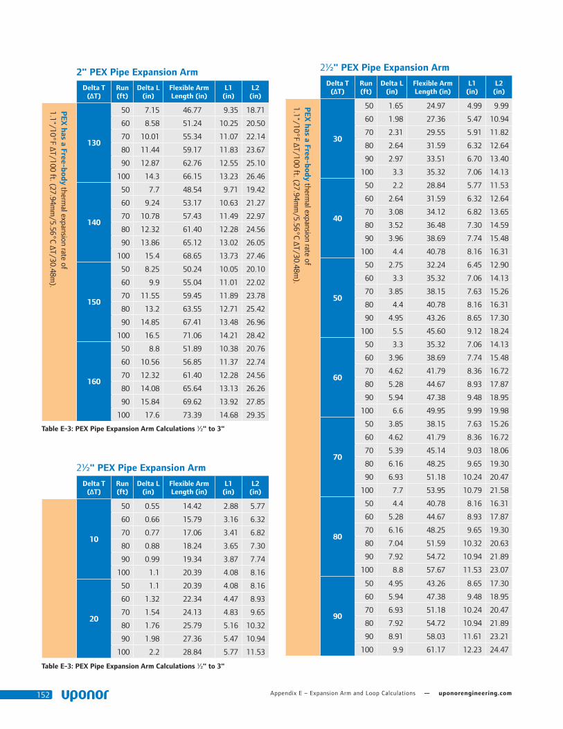
Appendix E – Expansion Arm and Loop Calculations — uponorengineering.com152
Table E-3: PEX Pipe Expansion Arm Calculations ½" to 3"
Table E-3: PEX Pipe Expansion Arm Calculations ½" to 3"
2" PEX Pipe Expansion Arm
Delta T (ΔT)
Run (ft)
Delta L (in)
Flexible Arm Length (in)
L1 (in)
L2 (in)
PEX
has a Free-body thermal expansion rate of
1.1"/10°F ΔT/100 ft. (27.94mm
/5.56°C ΔT/30.48m).
130
50 7.15 46.77 9.35 18.71
60 8.58 51.24 10.25 20.50
70 10.01 55.34 11.07 22.14
80 11.44 59.17 11.83 23.67
90 12.87 62.76 12.55 25.10
100 14.3 66.15 13.23 26.46
140
50 7.7 48.54 9.71 19.42
60 9.24 53.17 10.63 21.27
70 10.78 57.43 11.49 22.97
80 12.32 61.40 12.28 24.56
90 13.86 65.12 13.02 26.05
100 15.4 68.65 13.73 27.46
150
50 8.25 50.24 10.05 20.10
60 9.9 55.04 11.01 22.02
70 11.55 59.45 11.89 23.78
80 13.2 63.55 12.71 25.42
90 14.85 67.41 13.48 26.96
100 16.5 71.06 14.21 28.42
160
50 8.8 51.89 10.38 20.76
60 10.56 56.85 11.37 22.74
70 12.32 61.40 12.28 24.56
80 14.08 65.64 13.13 26.26
90 15.84 69.62 13.92 27.85
100 17.6 73.39 14.68 29.35
2½" PEX Pipe Expansion Arm
Delta T (ΔT)
Run (ft)
Delta L (in)
Flexible Arm Length (in)
L1 (in)
L2 (in)
10
50 0.55 14.42 2.88 5.77
60 0.66 15.79 3.16 6.32
70 0.77 17.06 3.41 6.82
80 0.88 18.24 3.65 7.30
90 0.99 19.34 3.87 7.74
100 1.1 20.39 4.08 8.16
20
50 1.1 20.39 4.08 8.16
60 1.32 22.34 4.47 8.93
70 1.54 24.13 4.83 9.65
80 1.76 25.79 5.16 10.32
90 1.98 27.36 5.47 10.94
100 2.2 28.84 5.77 11.53
2½" PEX Pipe Expansion Arm
Delta T (ΔT)
Run (ft)
Delta L (in)
Flexible Arm Length (in)
L1 (in)
L2 (in)
PEX
has a Free-body thermal expansion rate of
1.1"/10°F ΔT/100 ft. (27.94mm
/5.56°C ΔT/30.48m).
30
50 1.65 24.97 4.99 9.99
60 1.98 27.36 5.47 10.94
70 2.31 29.55 5.91 11.82
80 2.64 31.59 6.32 12.64
90 2.97 33.51 6.70 13.40
100 3.3 35.32 7.06 14.13
40
50 2.2 28.84 5.77 11.53
60 2.64 31.59 6.32 12.64
70 3.08 34.12 6.82 13.65
80 3.52 36.48 7.30 14.59
90 3.96 38.69 7.74 15.48
100 4.4 40.78 8.16 16.31
50
50 2.75 32.24 6.45 12.90
60 3.3 35.32 7.06 14.13
70 3.85 38.15 7.63 15.26
80 4.4 40.78 8.16 16.31
90 4.95 43.26 8.65 17.30
100 5.5 45.60 9.12 18.24
60
50 3.3 35.32 7.06 14.13
60 3.96 38.69 7.74 15.48
70 4.62 41.79 8.36 16.72
80 5.28 44.67 8.93 17.87
90 5.94 47.38 9.48 18.95
100 6.6 49.95 9.99 19.98
70
50 3.85 38.15 7.63 15.26
60 4.62 41.79 8.36 16.72
70 5.39 45.14 9.03 18.06
80 6.16 48.25 9.65 19.30
90 6.93 51.18 10.24 20.47
100 7.7 53.95 10.79 21.58
80
50 4.4 40.78 8.16 16.31
60 5.28 44.67 8.93 17.87
70 6.16 48.25 9.65 19.30
80 7.04 51.59 10.32 20.63
90 7.92 54.72 10.94 21.89
100 8.8 57.67 11.53 23.07
90
50 4.95 43.26 8.65 17.30
60 5.94 47.38 9.48 18.95
70 6.93 51.18 10.24 20.47
80 7.92 54.72 10.94 21.89
90 8.91 58.03 11.61 23.21
100 9.9 61.17 12.23 24.47

Plumbing Design Assistance Manual — Appendix E – Expansion Arm and Loop Calculations 153
Table E-3: PEX Pipe Expansion Arm Calculations ½" to 3"
3" PEX Pipe Expansion Arm
Delta T (ΔT)
Run (ft)
Delta L (in)
Flexible Arm Length (in)
L1 (in)
L2 (in)
PEX
has a Free-body thermal expansion rate of
1.1"/10°F ΔT/100 ft. (27.94mm
/5.56°C ΔT/30.48m).
10
50 0.55 15.73 3.15 6.29
60 0.66 17.23 3.45 6.89
70 0.77 18.61 3.72 7.45
80 0.88 19.90 3.98 7.96
90 0.99 21.11 4.22 8.44
100 1.1 22.25 4.45 8.90
20
50 1.1 22.25 4.45 8.90
60 1.32 24.37 4.87 9.75
70 1.54 26.32 5.26 10.53
80 1.76 28.14 5.63 11.26
90 1.98 29.85 5.97 11.94
100 2.2 31.46 6.29 12.59
30
50 1.65 27.25 5.45 10.90
60 1.98 29.85 5.97 11.94
70 2.31 32.24 6.45 12.90
80 2.64 34.47 6.89 13.79
90 2.97 36.56 7.31 14.62
100 3.3 38.54 7.71 15.41
40
50 2.2 31.46 6.29 12.59
60 2.64 34.47 6.89 13.79
70 3.08 37.23 7.45 14.89
80 3.52 39.80 7.96 15.92
90 3.96 42.21 8.44 16.89
100 4.4 44.50 8.90 17.80
50
50 2.75 35.18 7.04 14.07
60 3.3 38.54 7.71 15.41
70 3.85 41.62 8.32 16.65
80 4.4 44.50 8.90 17.80
90 4.95 47.20 9.44 18.88
100 5.5 49.75 9.95 19.90
60
50 3.3 38.54 7.71 15.41
60 3.96 42.21 8.44 16.89
70 4.62 45.60 9.12 18.24
80 5.28 48.74 9.75 19.50
90 5.94 51.70 10.34 20.68
100 6.6 54.50 10.90 21.80
70
50 3.85 41.62 8.32 16.65
60 4.62 45.60 9.12 18.24
70 5.39 49.25 9.85 19.70
80 6.16 52.65 10.53 21.06
90 6.93 55.84 11.17 22.34
100 7.7 58.86 11.77 23.55
2½" PEX Pipe Expansion Arm
Delta T (ΔT)
Run (ft)
Delta L (in)
Flexible Arm Length (in)
L1 (in)
L2 (in)
PEX
has a Free-body thermal expansion rate of
1.1"/10°F ΔT/100 ft. (27.94mm
/5.56°C ΔT/30.48m).
100
50 5.5 45.60 9.12 18.24
60 6.6 49.95 9.99 19.98
70 7.7 53.95 10.79 21.58
80 8.8 57.67 11.53 23.07
90 9.9 61.17 12.23 24.47
100 11 64.48 12.90 25.79
110
50 6.05 47.82 9.56 19.13
60 7.26 52.39 10.48 20.95
70 8.47 56.58 11.32 22.63
80 9.68 60.49 12.10 24.20
90 10.89 64.16 12.83 25.66
100 12.1 67.63 13.53 27.05
120
50 6.6 49.95 9.99 19.98
60 7.92 54.72 10.94 21.89
70 9.24 59.10 11.82 23.64
80 10.56 63.18 12.64 25.27
90 11.88 67.01 13.40 26.80
100 13.2 70.64 14.13 28.25
130
50 7.15 51.99 10.40 20.79
60 8.58 56.95 11.39 22.78
70 10.01 61.51 12.30 24.60
80 11.44 65.76 13.15 26.30
90 12.87 69.75 13.95 27.90
100 14.3 73.52 14.70 29.41
140
50 7.7 53.95 10.79 21.58
60 9.24 59.10 11.82 23.64
70 10.78 63.83 12.77 25.53
80 12.32 68.24 13.65 27.30
90 13.86 72.38 14.48 28.95
100 15.4 76.30 15.26 30.52
150
50 8.25 55.84 11.17 22.34
60 9.9 61.17 12.23 24.47
70 11.55 66.07 13.21 26.43
80 13.2 70.64 14.13 28.25
90 14.85 74.92 14.98 29.97
100 16.5 78.97 15.79 31.59
160
50 8.8 57.67 11.53 23.07
60 10.56 63.18 12.64 25.27
70 12.32 68.24 13.65 27.30
80 14.08 72.95 14.59 29.18
90 15.84 77.38 15.48 30.95
100 17.6 81.56 16.31 32.63

Appendix E – Expansion Arm and Loop Calculations — uponorengineering.com154
3" PEX Pipe Expansion Arm
Delta T (ΔT)
Run (ft)
Delta L (in)
Flexible Arm Length (in)
L1 (in)
L2 (in)
PEX
has a Free-body thermal expansion rate of
1.1"/10°F ΔT/100 ft. (27.94mm
/5.56°C ΔT/30.48m).
80
50 4.4 44.50 8.90 17.80
60 5.28 48.74 9.75 19.50
70 6.16 52.65 10.53 21.06
80 7.04 56.28 11.26 22.51
90 7.92 59.70 11.94 23.88
100 8.8 62.93 12.59 25.17
90
50 4.95 47.20 9.44 18.88
60 5.94 51.70 10.34 20.68
70 6.93 55.84 11.17 22.34
80 7.92 59.70 11.94 23.88
90 8.91 63.32 12.66 25.33
100 9.9 66.75 13.35 26.70
100
50 5.5 49.75 9.95 19.90
60 6.6 54.50 10.90 21.80
70 7.7 58.86 11.77 23.55
80 8.8 62.93 12.59 25.17
90 9.9 66.75 13.35 26.70
100 11 70.36 14.07 28.14
110
50 6.05 52.18 10.44 20.87
60 7.26 57.16 11.43 22.86
70 8.47 61.74 12.35 24.69
80 9.68 66.00 13.20 26.40
90 10.89 70.00 14.00 28.00
100 12.1 73.79 14.76 29.52
120
50 6.6 54.50 10.90 21.80
60 7.92 59.70 11.94 23.88
70 9.24 64.48 12.90 25.79
80 10.56 68.93 13.79 27.57
90 11.88 73.12 14.62 29.25
100 13.2 77.07 15.41 30.83
130
50 7.15 56.72 11.34 22.69
60 8.58 62.14 12.43 24.85
70 10.01 67.12 13.42 26.85
80 11.44 71.75 14.35 28.70
90 12.87 76.10 15.22 30.44
100 14.3 80.22 16.04 32.09
140
50 7.7 58.86 11.77 23.55
60 9.24 64.48 12.90 25.79
70 10.78 69.65 13.93 27.86
80 12.32 74.46 14.89 29.78
90 13.86 78.97 15.79 31.59
100 15.4 83.25 16.65 33.30
3" PEX Pipe Expansion Arm
Delta T (ΔT)
Run (ft)
Delta L (in)
Flexible Arm Length (in)
L1 (in)
L2 (in)
150
50 8.25 60.93 12.19 24.37
60 9.9 66.75 13.35 26.70
70 11.55 72.09 14.42 28.84
80 13.2 77.07 15.41 30.83
90 14.85 81.75 16.35 32.70
100 16.5 86.17 17.23 34.47
160
50 8.8 62.93 12.59 25.17
60 10.56 68.93 13.79 27.57
70 12.32 74.46 14.89 29.78
80 14.08 79.60 15.92 31.84
90 15.84 84.43 16.89 33.77
100 17.6 88.99 17.80 35.60
Table E-3: PEX Pipe Expansion Arm Calculations ½" to 3"

Plumbing Design Assistance Manual — Appendix F – Pipe Heat Loss and Surface Temperature 155
Appendix F
Pipe Heat Loss and Surface Temperature
1⁄2" Uponor PEX Surface Temperature at 50°F/10°C Ambient
Water Temp (ºF)
Surface Temperature (°F)
No Insulation
½" Insulation
1" Insulation
1½" Insulation
2" Insulation
30 30.7 45.2 47.7 48.6 49.0
40 40.4 47.6 48.8 49.3 49.5
50 50.0 50.0 50.0 50.0 50.0
60 59.6 52.4 51.2 50.7 50.5
70 69.3 54.8 52.3 51.4 51.0
80 78.9 57.1 53.5 52.1 51.5
90 88.6 59.5 54.6 52.9 52.0
100 98.2 61.9 55.8 53.6 52.5
110 107.9 64.3 56.9 54.3 53.0
120 117.5 66.7 58.1 55.0 53.5
130 127.2 69.0 59.2 55.7 54.0
140 136.8 71.4 60.4 56.4 54.5
150 146.5 73.8 61.5 57.2 55.1
160 156.1 76.2 62.7 57.9 55.6
170 165.8 78.6 63.8 58.6 56.1
180 175.4 81.0 65.0 59.3 56.6
190 185.1 83.3 66.1 60.0 57.1
200 194.7 85.7 67.3 60.7 57.6
1⁄2" Uponor PEX Heat Loss at 50°F/10°C Ambient
Water Temp (ºF)
Heat Loss (Btu/hr·ft)
No Insulation
½" Insulation
1" Insulation
1½" Insulation
2" Insulation
30 -3.2 -2.0 -1.6 -1.4 -1.2
40 -1.6 -1.0 -0.8 -0.7 -0.6
50 0.0 0.0 0.0 0.0 0.0
60 1.6 1.0 0.8 0.7 0.6
70 3.2 2.0 1.6 1.4 1.2
80 4.7 3.0 2.4 2.0 1.8
90 6.3 4.1 3.2 2.7 2.4
100 7.9 5.1 4.0 3.4 3.1
110 9.5 6.1 4.7 4.1 3.7
120 11.1 7.1 5.5 4.8 4.3
130 12.6 8.1 6.3 5.4 4.9
140 14.2 9.1 7.1 6.1 5.5
150 15.8 10.1 7.9 6.8 6.1
160 17.4 11.1 8.7 7.5 6.7
170 18.9 12.2 9.5 8.2 7.3
180 20.5 13.2 10.3 8.8 8.0
190 22.1 14.2 11.1 9.5 8.6
200 23.7 15.2 11.9 10.2 9.2
1. All calculations based on cylindrical thermal resistance methodology (ASHRAE).
2. Based on fluid velocity of 8 ft./sec. at 160°F/71.1°C (maximizing heat transfer from 100% water).
3. Pipe convection set to be 1.761 Btu/hr•ft²•°F (based on standard value for free convection of air).
4. This heat loss comparison uses 0.24 Btu•in/(hr•ft2•°F) as the insulation thermal conductivity. This is a standard value for fiberglass pipe insulation at a 100°F/37.8°C mean temperature.

Appendix F – Pipe Heat Loss and Surface Temperature — uponorengineering.com156
Pipe Heat Loss and Surface Temperature
3⁄4" Uponor PEX Surface Temperature at 50°F/10°C Ambient
Water Temp (ºF)
Surface Temperature (°F)
No Insulation
½" Insulation
1" Insulation
1½" Insulation
2" Insulation
30 30.9 45.0 47.5 48.4 48.9
40 40.5 47.5 48.7 49.2 49.4
50 50.0 50.0 50.0 50.0 50.0
60 59.5 52.5 51.3 50.8 50.6
70 69.1 55.0 52.5 51.6 51.1
80 78.6 57.6 53.8 52.4 51.7
90 88.2 60.1 55.0 53.1 52.2
100 97.7 62.6 56.3 53.9 52.8
110 107.3 65.1 57.5 54.7 53.3
120 116.8 67.7 58.8 55.5 53.9
130 126.3 70.2 60.0 56.3 54.4
140 135.9 72.7 61.3 57.1 55.0
150 145.4 75.2 62.5 57.8 55.6
160 155.0 77.8 63.8 58.6 56.1
170 164.5 80.3 65.0 59.4 56.7
180 174.1 82.8 66.3 60.2 57.2
190 183.6 85.3 67.5 61.0 57.8
200 193.1 87.9 68.8 61.8 58.3
3⁄4" Uponor PEX Heat Loss at 50°F/10°C Ambient
Water Temp (ºF)
Heat Loss (Btu/hr·ft)
No Insulation
½" Insulation
1" Insulation
1½" Insulation
2" Insulation
30 -4.4 -2.5 -1.9 -1.6 -1.4
40 -2.2 -1.2 -0.9 -0.8 -0.7
50 0.0 0.0 0.0 0.0 0.0
60 2.2 1.2 0.9 0.8 0.7
70 4.4 2.5 1.9 1.6 1.4
80 6.6 3.7 2.8 2.4 2.1
90 8.7 5.0 3.8 3.2 2.8
100 10.9 6.2 4.7 4.0 3.5
110 13.1 7.4 5.6 4.8 4.3
120 15.3 8.7 6.6 5.6 5.0
130 17.5 9.9 7.5 6.4 5.7
140 19.7 11.2 8.5 7.2 6.4
150 21.9 12.4 9.4 8.0 7.1
160 24.0 13.6 10.4 8.8 7.8
170 26.2 14.9 11.3 9.6 8.5
180 28.4 16.1 12.2 10.3 9.2
190 30.6 17.4 13.2 11.1 9.9
200 32.8 18.6 14.1 11.9 10.6
1. All calculations based on cylindrical thermal resistance methodology (ASHRAE).
2. Based on fluid velocity of 8 ft./sec. at 160°F/71.1°C (maximizing heat transfer from 100% water).
3. Pipe convection set to be 1.761 Btu/hr•ft²•°F (based on standard value for free convection of air).
4. This heat loss comparison uses 0.24 Btu•in/(hr•ft2•°F) as the insulation thermal conductivity. This is a standard value for fiberglass pipe insulation at a 100°F/37.8°C mean temperature.

Plumbing Design Assistance Manual — Appendix F – Pipe Heat Loss and Surface Temperature 157
Pipe Heat Loss and Surface Temperature
1" Uponor PEX Surface Temperature at 50°F/10°C Ambient
Water Temp (ºF)
Surface Temperature (°F)
No Insulation
½" Insulation
1" Insulation
1½" Insulation
2" Insulation
30 31.2 44.8 47.4 48.3 48.8
40 40.6 47.4 48.7 49.2 49.4
50 50.0 50.0 50.0 50.0 50.0
60 59.4 52.6 51.3 50.8 50.6
70 68.8 55.2 52.6 51.7 51.2
80 78.3 57.9 54.0 52.5 51.8
90 87.7 60.5 55.3 53.3 52.4
100 97.1 63.1 56.6 54.2 53.0
110 106.5 65.7 57.9 55.0 53.6
120 115.9 68.3 59.3 55.9 54.2
130 125.3 70.9 60.6 56.7 54.8
140 134.8 73.6 61.9 57.5 55.3
150 144.2 76.2 63.2 58.4 55.9
160 153.6 78.8 64.6 59.2 56.5
170 163.0 81.4 65.9 60.0 57.1
180 172.4 84.0 67.2 60.9 57.7
190 181.9 86.7 68.5 61.7 58.3
200 191.3 89.3 69.8 62.6 58.9
1" Uponor PEX Heat Loss at 50°F/10°C Ambient
Water Temp (ºF)
Heat Loss (Btu/hr·ft)
No Insulation
½" Insulation
1" Insulation
1½" Insulation
2" Insulation
30 -5.5 -2.9 -2.2 -1.8 -1.6
40 -2.8 -1.5 -1.1 -0.9 -0.8
50 0.0 0.0 0.0 0.0 0.0
60 2.8 1.5 1.1 0.9 0.8
70 5.5 2.9 2.2 1.8 1.6
80 8.3 4.4 3.2 2.7 2.4
90 11.1 5.8 4.3 3.6 3.2
100 13.9 7.3 5.4 4.5 4.0
110 16.6 8.7 6.5 5.4 4.8
120 19.4 10.2 7.6 6.3 5.6
130 22.2 11.7 8.7 7.2 6.4
140 25.0 13.1 9.7 8.1 7.2
150 27.7 14.6 10.8 9.0 8.0
160 30.5 16.0 11.9 9.9 8.8
170 33.3 17.5 13.0 10.8 9.6
180 36.1 18.9 14.1 11.8 10.4
190 38.8 20.4 15.2 12.7 11.2
200 41.6 21.8 16.2 13.6 12.0
1. All calculations based on cylindrical thermal resistance methodology (ASHRAE).
2. Based on fluid velocity of 8 ft./sec. at 160°F/71.1°C (maximizing heat transfer from 100% water).
3. Pipe convection set to be 1.761 Btu/hr•ft²•°F (based on standard value for free convection of air).
4. This heat loss comparison uses 0.24 Btu•in/(hr•ft2•°F) as the insulation thermal conductivity. This is a standard value for fiberglass pipe insulation at a 100°F/37.8°C mean temperature.

Appendix F – Pipe Heat Loss and Surface Temperature — uponorengineering.com158
Pipe Heat Loss and Surface Temperature
1 1⁄4" Uponor PEX Surface Temperature at 50°F/10°C Ambient
Water Temp (ºF)
Surface Temperature (°F)
No Insulation
½" Insulation
1" Insulation
1½" Insulation
2" Insulation
30 31.4 44.6 47.2 48.2 48.7
40 40.7 47.3 48.6 49.1 49.4
50 50.0 50.0 50.0 50.0 50.0
60 59.3 52.7 51.4 50.9 50.6
70 68.6 55.4 52.8 51.8 51.3
80 77.9 58.1 54.1 52.6 51.9
90 87.2 60.7 55.5 53.5 52.5
100 96.5 63.4 56.9 54.4 53.1
110 105.8 66.1 58.3 55.3 53.8
120 115.1 68.8 59.7 56.2 54.4
130 124.4 71.5 61.0 57.0 55.0
140 133.7 74.2 62.4 57.9 55.6
150 143.0 76.8 63.8 58.8 56.3
160 152.3 79.5 65.2 59.7 56.9
170 161.6 82.2 66.6 60.6 57.5
180 170.9 84.9 67.9 61.4 58.2
190 180.2 87.6 69.3 62.3 58.8
200 189.5 90.3 70.7 63.2 59.4
1 1⁄4" Uponor PEX Heat Loss at 50°F/10°C Ambient
Water Temp (ºF)
Heat Loss (Btu/hr·ft)
No Insulation
½" Insulation
1" Insulation
1½" Insulation
2" Insulation
30 -6.7 -3.3 -2.4 -2.0 -1.8
40 -3.3 -1.7 -1.2 -1.0 -0.9
50 0.0 0.0 0.0 0.0 0.0
60 3.3 1.7 1.2 1.0 0.9
70 6.7 3.3 2.4 2.0 1.8
80 10.0 5.0 3.7 3.0 2.6
90 13.4 6.7 4.9 4.0 3.5
100 16.7 8.3 6.1 5.0 4.4
110 20.1 10.0 7.3 6.0 5.3
120 23.4 11.7 8.5 7.1 6.2
130 26.8 13.3 9.8 8.1 7.1
140 30.1 15.0 11.0 9.1 7.9
150 33.5 16.7 12.2 10.1 8.8
160 36.8 18.4 13.4 11.1 9.7
170 40.2 20.0 14.6 12.1 10.6
180 43.5 21.7 15.9 13.1 11.5
190 46.9 23.4 17.1 14.1 12.4
200 50.2 25.0 18.3 15.1 13.2
1. All calculations based on cylindrical thermal resistance methodology (ASHRAE).
2. Based on fluid velocity of 8 ft./sec. at 160°F/71.1°C (maximizing heat transfer from 100% water).
3. Pipe convection set to be 1.761 Btu/hr•ft²•°F (based on standard value for free convection of air).
4. This heat loss comparison uses 0.24 Btu•in/(hr•ft2•°F) as the insulation thermal conductivity. This is a standard value for fiberglass pipe insulation at a 100°F/37.8°C mean temperature.
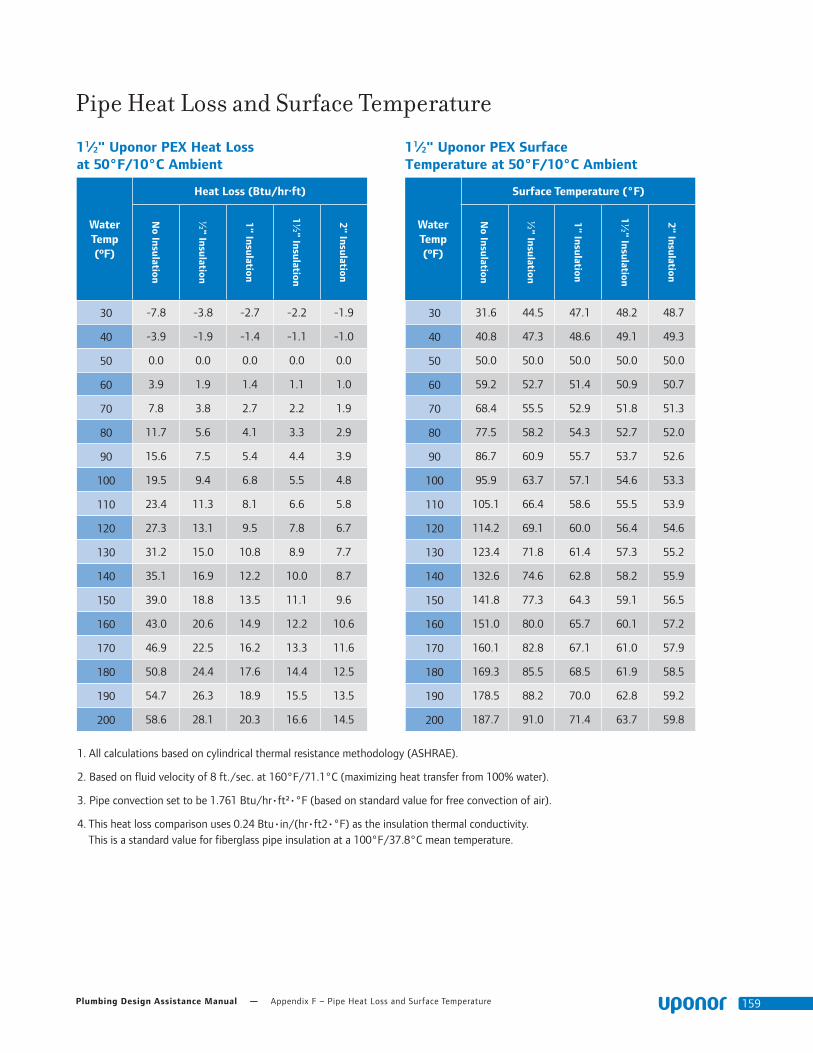
Plumbing Design Assistance Manual — Appendix F – Pipe Heat Loss and Surface Temperature 159
Pipe Heat Loss and Surface Temperature
1 1⁄2" Uponor PEX Surface Temperature at 50°F/10°C Ambient
Water Temp (ºF)
Surface Temperature (°F)
No Insulation
½" Insulation
1" Insulation
1½" Insulation
2" Insulation
30 31.6 44.5 47.1 48.2 48.7
40 40.8 47.3 48.6 49.1 49.3
50 50.0 50.0 50.0 50.0 50.0
60 59.2 52.7 51.4 50.9 50.7
70 68.4 55.5 52.9 51.8 51.3
80 77.5 58.2 54.3 52.7 52.0
90 86.7 60.9 55.7 53.7 52.6
100 95.9 63.7 57.1 54.6 53.3
110 105.1 66.4 58.6 55.5 53.9
120 114.2 69.1 60.0 56.4 54.6
130 123.4 71.8 61.4 57.3 55.2
140 132.6 74.6 62.8 58.2 55.9
150 141.8 77.3 64.3 59.1 56.5
160 151.0 80.0 65.7 60.1 57.2
170 160.1 82.8 67.1 61.0 57.9
180 169.3 85.5 68.5 61.9 58.5
190 178.5 88.2 70.0 62.8 59.2
200 187.7 91.0 71.4 63.7 59.8
1 1⁄2" Uponor PEX Heat Loss at 50°F/10°C Ambient
Water Temp (ºF)
Heat Loss (Btu/hr·ft)
No Insulation
½" Insulation
1" Insulation
1½" Insulation
2" Insulation
30 -7.8 -3.8 -2.7 -2.2 -1.9
40 -3.9 -1.9 -1.4 -1.1 -1.0
50 0.0 0.0 0.0 0.0 0.0
60 3.9 1.9 1.4 1.1 1.0
70 7.8 3.8 2.7 2.2 1.9
80 11.7 5.6 4.1 3.3 2.9
90 15.6 7.5 5.4 4.4 3.9
100 19.5 9.4 6.8 5.5 4.8
110 23.4 11.3 8.1 6.6 5.8
120 27.3 13.1 9.5 7.8 6.7
130 31.2 15.0 10.8 8.9 7.7
140 35.1 16.9 12.2 10.0 8.7
150 39.0 18.8 13.5 11.1 9.6
160 43.0 20.6 14.9 12.2 10.6
170 46.9 22.5 16.2 13.3 11.6
180 50.8 24.4 17.6 14.4 12.5
190 54.7 26.3 18.9 15.5 13.5
200 58.6 28.1 20.3 16.6 14.5
1. All calculations based on cylindrical thermal resistance methodology (ASHRAE).
2. Based on fluid velocity of 8 ft./sec. at 160°F/71.1°C (maximizing heat transfer from 100% water).
3. Pipe convection set to be 1.761 Btu/hr•ft²•°F (based on standard value for free convection of air).
4. This heat loss comparison uses 0.24 Btu•in/(hr•ft2•°F) as the insulation thermal conductivity. This is a standard value for fiberglass pipe insulation at a 100°F/37.8°C mean temperature.
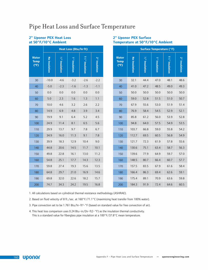
Appendix F – Pipe Heat Loss and Surface Temperature — uponorengineering.com160
Pipe Heat Loss and Surface Temperature
2" Uponor PEX Surface Temperature at 50°F/10°C Ambient
Water Temp (ºF)
Surface Temperature (°F)
No Insulation
½" Insulation
1" Insulation
1½" Insulation
2" Insulation
30 32.1 44.4 47.0 48.1 48.6
40 41.0 47.2 48.5 49.0 49.3
50 50.0 50.0 50.0 50.0 50.0
60 59.0 52.8 51.5 51.0 50.7
70 67.9 55.6 53.0 51.9 51.4
80 76.9 58.4 54.5 52.9 52.1
90 85.8 61.2 56.0 53.9 52.8
100 94.8 64.0 57.5 54.9 53.5
110 103.7 66.8 59.0 55.8 54.2
120 112.7 69.5 60.5 56.8 54.9
130 121.7 72.3 61.9 57.8 55.6
140 130.6 75.1 63.4 58.7 56.3
150 139.6 77.9 64.9 59.7 57.0
160 148.5 80.7 66.4 60.7 57.7
170 157.5 83.5 67.9 61.6 58.4
180 166.4 86.3 69.4 62.6 59.1
190 175.4 89.1 70.9 63.6 59.8
200 184.3 91.9 72.4 64.6 60.5
2" Uponor PEX Heat Loss at 50°F/10°C Ambient
Water Temp (ºF)
Heat Loss (Btu/hr·ft)
No Insulation
½" Insulation
1" Insulation
1½" Insulation
2" Insulation
30 -10.0 -4.6 -3.2 -2.6 -2.2
40 -5.0 -2.3 -1.6 -1.3 -1.1
50 0.0 0.0 0.0 0.0 0.0
60 5.0 2.3 1.6 1.3 1.1
70 10.0 4.6 3.2 2.6 2.2
80 14.9 6.9 4.8 3.9 3.4
90 19.9 9.1 6.4 5.2 4.5
100 24.9 11.4 8.1 6.5 5.6
110 29.9 13.7 9.7 7.8 6.7
120 34.9 16.0 11.3 9.1 7.8
130 39.9 18.3 12.9 10.4 9.0
140 44.8 20.6 14.5 11.7 10.1
150 49.8 22.8 16.1 13.0 11.2
160 54.8 25.1 17.7 14.3 12.3
170 59.8 27.4 19.3 15.6 13.5
180 64.8 29.7 21.0 16.9 14.6
190 69.8 32.0 22.6 18.2 15.7
200 74.7 34.3 24.2 19.5 16.8
1. All calculations based on cylindrical thermal resistance methodology (ASHRAE).
2. Based on fluid velocity of 8 ft./sec. at 160°F/71.1°C (maximizing heat transfer from 100% water).
3. Pipe convection set to be 1.761 Btu/hr•ft²•°F (based on standard value for free convection of air).
4. This heat loss comparison uses 0.24 Btu•in/(hr•ft2•°F) as the insulation thermal conductivity. This is a standard value for fiberglass pipe insulation at a 100°F/37.8°C mean temperature.

Plumbing Design Assistance Manual — Appendix F – Pipe Heat Loss and Surface Temperature 161
Pipe Heat Loss and Surface Temperature
2 1⁄2" Uponor PEX Surface Temperature at 50°F/10°C Ambient
Water Temp (ºF)
Surface Temperature (°F)
No Insulation
½" Insulation
1" Insulation
1½" Insulation
2" Insulation
30 32.5 44.3 46.9 48.0 48.5
40 41.3 47.2 48.5 49.0 49.3
50 50.0 50.0 50.0 50.0 50.0
60 58.7 52.8 51.5 51.0 50.7
70 67.5 55.7 53.1 52.0 51.5
80 76.2 58.5 54.6 53.0 52.2
90 85.0 61.3 56.2 54.0 52.9
100 93.7 64.1 57.7 55.1 53.7
110 102.4 67.0 59.2 56.1 54.4
120 111.2 69.8 60.8 57.1 55.1
130 119.9 72.6 62.3 58.1 55.9
140 128.7 75.4 63.9 59.1 56.6
150 137.4 78.3 65.4 60.1 57.3
160 146.1 81.1 66.9 61.1 58.1
170 154.9 83.9 68.5 62.1 58.8
180 163.6 86.7 70.0 63.2 59.5
190 172.3 89.6 71.6 64.2 60.3
200 181.1 92.4 73.1 65.2 61.0
2 1⁄2" Uponor PEX Heat Loss at 50°F/10°C Ambient
Water Temp (ºF)
Heat Loss (Btu/hr·ft)
No Insulation
½" Insulation
1" Insulation
1½" Insulation
2" Insulation
30 -12.0 -5.4 -3.7 -3.0 -2.5
40 -6.0 -2.7 -1.9 -1.5 -1.3
50 0.0 0.0 0.0 0.0 0.0
60 6.0 2.7 1.9 1.5 1.3
70 12.0 5.4 3.7 3.0 2.5
80 18.0 8.0 5.6 4.5 3.8
90 24.0 10.7 7.5 6.0 5.1
100 30.0 13.4 9.3 7.5 6.4
110 36.0 16.1 11.2 8.9 7.6
120 42.0 18.8 13.1 10.4 8.9
130 48.0 21.5 14.9 11.9 10.2
140 54.1 24.1 16.8 13.4 11.5
150 60.1 26.8 18.6 14.9 12.7
160 66.1 29.5 20.5 16.4 14.0
170 72.1 32.2 22.4 17.9 15.3
180 78.1 34.9 24.2 19.4 16.5
190 84.1 37.5 26.1 20.9 17.8
200 90.1 40.2 28.0 22.4 19.1
1. All calculations based on cylindrical thermal resistance methodology (ASHRAE).
2. Based on fluid velocity of 8 ft./sec. at 160°F/71.1°C (maximizing heat transfer from 100% water).
3. Pipe convection set to be 1.761 Btu/hr•ft²•°F (based on standard value for free convection of air).
4. This heat loss comparison uses 0.24 Btu•in/(hr•ft2•°F) as the insulation thermal conductivity. This is a standard value for fiberglass pipe insulation at a 100°F/37.8°C mean temperature.

Appendix F – Pipe Heat Loss and Surface Temperature — uponorengineering.com162
Pipe Heat Loss and Surface Temperature
3" Uponor PEX Surface Temperature at 50°F/10°C Ambient
Water Temp (ºF)
Surface Temperature (°F)
No Insulation
½" Insulation
1" Insulation
1½" Insulation
2" Insulation
30 32.9 44.3 46.9 47.9 48.5
40 41.5 47.2 48.4 49.0 49.2
50 50.0 50.0 50.0 50.0 50.0
60 58.5 52.8 51.6 51.0 50.8
70 67.1 55.7 53.1 52.1 51.5
80 75.6 58.5 54.7 53.1 52.3
90 84.2 61.4 56.3 54.2 53.0
100 92.7 64.2 57.9 55.2 53.8
110 101.3 67.1 59.4 56.3 54.6
120 109.8 69.9 61.0 57.3 55.3
130 118.3 72.8 62.6 58.4 56.1
140 126.9 75.6 64.2 59.4 56.9
150 135.4 78.4 65.7 60.4 57.6
160 144.0 81.3 67.3 61.5 58.4
170 152.5 84.1 68.9 62.5 59.1
180 161.0 87.0 70.5 63.6 59.9
190 169.6 89.8 72.0 64.6 60.7
200 178.1 92.7 73.6 65.7 61.4
3" Uponor PEX Heat Loss at 50°F/10°C Ambient
Water Temp (ºF)
Heat Loss (Btu/hr·ft)
No Insulation
½" Insulation
1" Insulation
1½" Insulation
2" Insulation
30 -14.0 -6.1 -4.2 -3.3 -2.8
40 -7.0 -3.1 -2.1 -1.7 -1.4
50 0.0 0.0 0.0 0.0 0.0
60 7.0 3.1 2.1 1.7 1.4
70 14.0 6.1 4.2 3.3 2.8
80 21.0 9.2 6.3 5.0 4.3
90 28.0 12.3 8.5 6.7 5.7
100 34.9 15.4 10.6 8.4 7.1
110 41.9 18.4 12.7 10.0 8.5
120 48.9 21.5 14.8 11.7 9.9
130 55.9 24.6 16.9 13.4 11.4
140 62.9 27.6 19.0 15.1 12.8
150 69.9 30.7 21.1 16.7 14.2
160 76.9 33.8 23.2 18.4 15.6
170 83.9 36.9 25.4 20.1 17.0
180 90.8 39.9 27.5 21.8 18.5
190 97.8 43.0 29.6 23.4 19.9
200 104.8 46.1 31.7 25.1 21.3
1. All calculations based on cylindrical thermal resistance methodology (ASHRAE).
2. Based on fluid velocity of 8 ft./sec. at 160°F/71.1°C (maximizing heat transfer from 100% water).
3. Pipe convection set to be 1.761 Btu/hr•ft²•°F (based on standard value for free convection of air).
4. This heat loss comparison uses 0.24 Btu•in/(hr•ft2•°F) as the insulation thermal conductivity. This is a standard value for fiberglass pipe insulation at a 100°F/37.8°C mean temperature.

Plumbing Design Assistance Manual — Appendix F – Pipe Heat Loss and Surface Temperature 163
Pipe Heat Loss and Surface Temperature1⁄2" Uponor PEX Surface Temperature at 70°F/21.1°C Ambient
Water Temp (ºF)
Surface Temperature (°F)
No Insulation
½" Insulation
1" Insulation
1½" Insulation
2" Insulation
30 31.4 60.5 65.4 67.1 68.0
40 41.1 62.9 66.5 67.9 68.5
50 50.7 65.2 67.7 68.6 69.0
60 60.4 67.6 68.8 69.3 69.5
70 70.0 70.0 70.0 70.0 70.0
80 79.6 72.4 71.2 70.7 70.5
90 89.3 74.8 72.3 71.4 71.0
100 98.9 77.1 73.5 72.1 71.5
110 108.6 79.5 74.6 72.9 72.0
120 118.2 81.9 75.8 73.6 72.5
130 127.9 84.3 76.9 74.3 73.0
140 137.5 86.7 78.1 75.0 73.5
150 147.2 89.0 79.2 75.7 74.0
160 156.8 91.4 80.4 76.4 74.5
170 166.5 93.8 81.5 77.2 75.1
180 176.1 96.2 82.7 77.9 75.6
190 185.8 98.6 83.8 78.6 76.1
200 195.4 101.0 85.0 79.3 76.6
1⁄2" Uponor PEX Heat Loss at 70°F/21.1°C Ambient
Water Temp (ºF)
Heat Loss (Btu/hr·ft)
No Insulation
½" Insulation
1" Insulation
1½" Insulation
2" Insulation
30 -6.3 -4.1 -3.2 -2.7 -2.4
40 -4.7 -3.0 -2.4 -2.0 -1.8
50 -3.2 -2.0 -1.6 -1.4 -1.2
60 -1.6 -1.0 -0.8 -0.7 -0.6
70 0.0 0.0 0.0 0.0 0.0
80 1.6 1.0 0.8 0.7 0.6
90 3.2 2.0 1.6 1.4 1.2
100 4.7 3.0 2.4 2.0 1.8
110 6.3 4.1 3.2 2.7 2.4
120 7.9 5.1 4.0 3.4 3.1
130 9.5 6.1 4.7 4.1 3.7
140 11.1 7.1 5.5 4.8 4.3
150 12.6 8.1 6.3 5.4 4.9
160 14.2 9.1 7.1 6.1 5.5
170 15.8 10.1 7.9 6.8 6.1
180 17.4 11.1 8.7 7.5 6.7
190 18.9 12.2 9.5 8.2 7.3
200 20.5 13.2 10.3 8.8 8.0
1. All calculations based on cylindrical thermal resistance methodology (ASHRAE).
2. Based on fluid velocity of 8 ft./sec. at 160°F/71.1°C (maximizing heat transfer from 100% water).
3. Pipe convection set to be 1.761 Btu/hr•ft²•°F (based on standard value for free convection of air).
4. This heat loss comparison uses 0.24 Btu•in/(hr•ft2•°F) as the insulation thermal conductivity. This is a standard value for fiberglass pipe insulation at a 100°F/37.8°C mean temperature.

Appendix F – Pipe Heat Loss and Surface Temperature — uponorengineering.com164
Pipe Heat Loss and Surface Temperature 3⁄4" Uponor PEX Surface Temperature at 70°F/21.1°C Ambient
Water Temp (ºF)
Surface Temperature (°F)
No Insulation
½" Insulation
1" Insulation
1½" Insulation
2" Insulation
30 31.8 59.9 65.0 66.9 67.8
40 41.4 62.4 66.2 67.6 68.3
50 50.9 65.0 67.5 68.4 68.9
60 60.5 67.5 68.7 69.2 69.4
70 70.0 70.0 70.0 70.0 70.0
80 79.5 72.5 71.3 70.8 70.6
90 89.1 75.0 72.5 71.6 71.1
100 98.6 77.6 73.8 72.4 71.7
110 108.2 80.1 75.0 73.1 72.2
120 117.7 82.6 76.3 73.9 72.8
130 127.3 85.1 77.5 74.7 73.3
140 136.8 87.7 78.8 75.5 73.9
150 146.3 90.2 80.0 76.3 74.4
160 155.9 92.7 81.3 77.1 75.0
170 165.4 95.2 82.5 77.8 75.6
180 175.0 97.8 83.8 78.6 76.1
190 184.5 100.3 85.0 79.4 76.7
200 194.1 102.8 86.3 80.2 77.2
3⁄4" Uponor PEX Heat Loss at 70°F/21.1°C Ambient
Water Temp (ºF)
Heat Loss (Btu/hr·ft)
No Insulation
½" Insulation
1" Insulation
1½" Insulation
2" Insulation
30 -8.7 -5.0 -3.8 -3.2 -2.8
40 -6.6 -3.7 -2.8 -2.4 -2.1
50 -4.4 -2.5 -1.9 -1.6 -1.4
60 -2.2 -1.2 -0.9 -0.8 -0.7
70 0.0 0.0 0.0 0.0 0.0
80 2.2 1.2 0.9 0.8 0.7
90 4.4 2.5 1.9 1.6 1.4
100 6.6 3.7 2.8 2.4 2.1
110 8.7 5.0 3.8 3.2 2.8
120 10.9 6.2 4.7 4.0 3.5
130 13.1 7.4 5.6 4.8 4.3
140 15.3 8.7 6.6 5.6 5.0
150 17.5 9.9 7.5 6.4 5.7
160 19.7 11.2 8.5 7.2 6.4
170 21.9 12.4 9.4 8.0 7.1
180 24.0 13.6 10.4 8.8 7.8
190 26.2 14.9 11.3 9.6 8.5
200 28.4 16.1 12.2 10.3 9.2
1. All calculations based on cylindrical thermal resistance methodology (ASHRAE).
2. Based on fluid velocity of 8 ft./sec. at 160°F/71.1°C (maximizing heat transfer from 100% water).
3. Pipe convection set to be 1.761 Btu/hr•ft²•°F (based on standard value for free convection of air).
4. This heat loss comparison uses 0.24 Btu•in/(hr•ft2•°F) as the insulation thermal conductivity. This is a standard value for fiberglass pipe insulation at a 100°F/37.8°C mean temperature.

Plumbing Design Assistance Manual — Appendix F – Pipe Heat Loss and Surface Temperature 165
Pipe Heat Loss and Surface Temperature
1" Uponor PEX Surface Temperature at 70°F/21.1°C Ambient
Water Temp (ºF)
Surface Temperature (°F)
No Insulation
½" Insulation
1" Insulation
1½" Insulation
2" Insulation
30 32.3 59.5 64.7 66.7 67.6
40 41.7 62.1 66.0 67.5 68.2
50 51.2 64.8 67.4 68.3 68.8
60 60.6 67.4 68.7 69.2 69.4
70 70.0 70.0 70.0 70.0 70.0
80 79.4 72.6 71.3 70.8 70.6
90 88.8 75.2 72.6 71.7 71.2
100 98.3 77.9 74.0 72.5 71.8
110 107.7 80.5 75.3 73.3 72.4
120 117.1 83.1 76.6 74.2 73.0
130 126.5 85.7 77.9 75.0 73.6
140 135.9 88.3 79.3 75.9 74.2
150 145.3 90.9 80.6 76.7 74.8
160 154.8 93.6 81.9 77.5 75.3
170 164.2 96.2 83.2 78.4 75.9
180 173.6 98.8 84.6 79.2 76.5
190 183.0 101.4 85.9 80.0 77.1
200 192.4 104.0 87.2 80.9 77.7
1" Uponor PEX Heat Loss at 70°F/21.1°C Ambient
Water Temp (ºF)
Heat Loss (Btu/hr·ft)
No Insulation
½" Insulation
1" Insulation
1½" Insulation
2" Insulation
30 -11.1 -5.8 -4.3 -3.6 -3.2
40 -8.3 -4.4 -3.2 -2.7 -2.4
50 -5.5 -2.9 -2.2 -1.8 -1.6
60 -2.8 -1.5 -1.1 -0.9 -0.8
70 0.0 0.0 0.0 0.0 0.0
80 2.8 1.5 1.1 0.9 0.8
90 5.5 2.9 2.2 1.8 1.6
100 8.3 4.4 3.2 2.7 2.4
110 11.1 5.8 4.3 3.6 3.2
120 13.9 7.3 5.4 4.5 4.0
130 16.6 8.7 6.5 5.4 4.8
140 19.4 10.2 7.6 6.3 5.6
150 22.2 11.7 8.7 7.2 6.4
160 25.0 13.1 9.7 8.1 7.2
170 27.7 14.6 10.8 9.0 8.0
180 30.5 16.0 11.9 9.9 8.8
190 33.3 17.5 13.0 10.8 9.6
200 36.1 18.9 14.1 11.8 10.4
1. All calculations based on cylindrical thermal resistance methodology (ASHRAE).
2. Based on fluid velocity of 8 ft./sec. at 160°F/71.1°C (maximizing heat transfer from 100% water).
3. Pipe convection set to be 1.761 Btu/hr•ft²•°F (based on standard value for free convection of air).
4. This heat loss comparison uses 0.24 Btu•in/(hr•ft2•°F) as the insulation thermal conductivity. This is a standard value for fiberglass pipe insulation at a 100°F/37.8°C mean temperature.

Appendix F – Pipe Heat Loss and Surface Temperature — uponorengineering.com166
Pipe Heat Loss and Surface Temperature
1 1⁄4" Uponor PEX Surface Temperature at 70°F/21.1°C Ambient
Water Temp (ºF)
Surface Temperature (°F)
No Insulation
½" Insulation
1" Insulation
1½" Insulation
2" Insulation
30 32.8 59.3 64.5 66.5 67.5
40 42.1 61.9 65.9 67.4 68.1
50 51.4 64.6 67.2 68.2 68.7
60 60.7 67.3 68.6 69.1 69.4
70 70.0 70.0 70.0 70.0 70.0
80 79.3 72.7 71.4 70.9 70.6
90 88.6 75.4 72.8 71.8 71.3
100 97.9 78.1 74.1 72.6 71.9
110 107.2 80.7 75.5 73.5 72.5
120 116.5 83.4 76.9 74.4 73.1
130 125.8 86.1 78.3 75.3 73.8
140 135.1 88.8 79.7 76.2 74.4
150 144.4 91.5 81.0 77.0 75.0
160 153.7 94.2 82.4 77.9 75.6
170 163.0 96.8 83.8 78.8 76.3
180 172.3 99.5 85.2 79.7 76.9
190 181.6 102.2 86.6 80.6 77.5
200 190.9 104.9 87.9 81.4 78.2
1 1⁄4" Uponor PEX Heat Loss at 70°F/21.1°C Ambient
Water Temp (ºF)
Heat Loss (Btu/hr·ft)
No Insulation
½" Insulation
1" Insulation
1½" Insulation
2" Insulation
30 -13.4 -6.7 -4.9 -4.0 -3.5
40 -10.0 -5.0 -3.7 -3.0 -2.6
50 -6.7 -3.3 -2.4 -2.0 -1.8
60 -3.3 -1.7 -1.2 -1.0 -0.9
70 0.0 0.0 0.0 0.0 0.0
80 3.3 1.7 1.2 1.0 0.9
90 6.7 3.3 2.4 2.0 1.8
100 10.0 5.0 3.7 3.0 2.6
110 13.4 6.7 4.9 4.0 3.5
120 16.7 8.3 6.1 5.0 4.4
130 20.1 10.0 7.3 6.0 5.3
140 23.4 11.7 8.5 7.1 6.2
150 26.8 13.3 9.8 8.1 7.1
160 30.1 15.0 11.0 9.1 7.9
170 33.5 16.7 12.2 10.1 8.8
180 36.8 18.4 13.4 11.1 9.7
190 40.2 20.0 14.6 12.1 10.6
200 43.5 21.7 15.9 13.1 11.5
1. All calculations based on cylindrical thermal resistance methodology (ASHRAE).
2. Based on fluid velocity of 8 ft./sec. at 160°F/71.1°C (maximizing heat transfer from 100% water).
3. Pipe convection set to be 1.761 Btu/hr•ft²•°F (based on standard value for free convection of air).
4. This heat loss comparison uses 0.24 Btu•in/(hr•ft2•°F) as the insulation thermal conductivity. This is a standard value for fiberglass pipe insulation at a 100°F/37.8°C mean temperature.

Plumbing Design Assistance Manual — Appendix F – Pipe Heat Loss and Surface Temperature 167
Pipe Heat Loss and Surface Temperature
1 1⁄2" Uponor PEX Surface Temperature at 70°F/21.1°C Ambient
Water Temp (ºF)
Surface Temperature (°F)
No Insulation
½" Insulation
1" Insulation
1½" Insulation
2" Insulation
30 33.3 59.1 64.3 66.3 67.4
40 42.5 61.8 65.7 67.3 68.0
50 51.6 64.5 67.1 68.2 68.7
60 60.8 67.3 68.6 69.1 69.3
70 70.0 70.0 70.0 70.0 70.0
80 79.2 72.7 71.4 70.9 70.7
90 88.4 75.5 72.9 71.8 71.3
100 97.5 78.2 74.3 72.7 72.0
110 106.7 80.9 75.7 73.7 72.6
120 115.9 83.7 77.1 74.6 73.3
130 125.1 86.4 78.6 75.5 73.9
140 134.2 89.1 80.0 76.4 74.6
150 143.4 91.8 81.4 77.3 75.2
160 152.6 94.6 82.8 78.2 75.9
170 161.8 97.3 84.3 79.1 76.5
180 171.0 100.0 85.7 80.1 77.2
190 180.1 102.8 87.1 81.0 77.9
200 189.3 105.5 88.5 81.9 78.5
1 1⁄2" Uponor PEX Heat Loss at 70°F/21.1°C Ambient
Water Temp (ºF)
Heat Loss (Btu/hr·ft)
No Insulation
½" Insulation
1" Insulation
1½" Insulation
2" Insulation
30 -15.6 -7.5 -5.4 -4.4 -3.9
40 -11.7 -5.6 -4.1 -3.3 -2.9
50 -7.8 -3.8 -2.7 -2.2 -1.9
60 -3.9 -1.9 -1.4 -1.1 -1.0
70 0.0 0.0 0.0 0.0 0.0
80 3.9 1.9 1.4 1.1 1.0
90 7.8 3.8 2.7 2.2 1.9
100 11.7 5.6 4.1 3.3 2.9
110 15.6 7.5 5.4 4.4 3.9
120 19.5 9.4 6.8 5.5 4.8
130 23.4 11.3 8.1 6.6 5.8
140 27.3 13.1 9.5 7.8 6.7
150 31.2 15.0 10.8 8.9 7.7
160 35.1 16.9 12.2 10.0 8.7
170 39.0 18.8 13.5 11.1 9.6
180 43.0 20.6 14.9 12.2 10.6
190 46.9 22.5 16.2 13.3 11.6
200 50.8 24.4 17.6 14.4 12.5
1. All calculations based on cylindrical thermal resistance methodology (ASHRAE).
2. Based on fluid velocity of 8 ft./sec. at 160°F/71.1°C (maximizing heat transfer from 100% water).
3. Pipe convection set to be 1.761 Btu/hr•ft²•°F (based on standard value for free convection of air).
4. This heat loss comparison uses 0.24 Btu•in/(hr•ft2•°F) as the insulation thermal conductivity. This is a standard value for fiberglass pipe insulation at a 100°F/37.8°C mean temperature.

Appendix F – Pipe Heat Loss and Surface Temperature — uponorengineering.com168
Pipe Heat Loss and Surface Temperature
2" Uponor PEX Surface Temperature at 70°F/21.1°C Ambient
Water Temp (ºF)
Surface Temperature (°F)
No Insulation
½" Insulation
1" Insulation
1½" Insulation
2" Insulation
30 34.2 58.8 64.0 66.1 67.2
40 43.1 61.6 65.5 67.1 67.9
50 52.1 64.4 67.0 68.1 68.6
60 61.0 67.2 68.5 69.0 69.3
70 70.0 70.0 70.0 70.0 70.0
80 79.0 72.8 71.5 71.0 70.7
90 87.9 75.6 73.0 71.9 71.4
100 96.9 78.4 74.5 72.9 72.1
110 105.8 81.2 76.0 73.9 72.8
120 114.8 84.0 77.5 74.9 73.5
130 123.7 86.8 79.0 75.8 74.2
140 132.7 89.5 80.5 76.8 74.9
150 141.7 92.3 81.9 77.8 75.6
160 150.6 95.1 83.4 78.7 76.3
170 159.6 97.9 84.9 79.7 77.0
180 168.5 100.7 86.4 80.7 77.7
190 177.5 103.5 87.9 81.6 78.4
200 186.4 106.3 89.4 82.6 79.1
2" Uponor PEX Heat Loss at 70°F/21.1°C Ambient
Water Temp (ºF)
Heat Loss (Btu/hr·ft)
No Insulation
½" Insulation
1" Insulation
1½" Insulation
2" Insulation
30 -19.9 -9.1 -6.4 -5.2 -4.5
40 -14.9 -6.9 -4.8 -3.9 -3.4
50 -10.0 -4.6 -3.2 -2.6 -2.2
60 -5.0 -2.3 -1.6 -1.3 -1.1
70 0.0 0.0 0.0 0.0 0.0
80 5.0 2.3 1.6 1.3 1.1
90 10.0 4.6 3.2 2.6 2.2
100 14.9 6.9 4.8 3.9 3.4
110 19.9 9.1 6.4 5.2 4.5
120 24.9 11.4 8.1 6.5 5.6
130 29.9 13.7 9.7 7.8 6.7
140 34.9 16.0 11.3 9.1 7.8
150 39.9 18.3 12.9 10.4 9.0
160 44.8 20.6 14.5 11.7 10.1
170 49.8 22.8 16.1 13.0 11.2
180 54.8 25.1 17.7 14.3 12.3
190 59.8 27.4 19.3 15.6 13.5
200 64.8 29.7 21.0 16.9 14.6
1. All calculations based on cylindrical thermal resistance methodology (ASHRAE).
2. Based on fluid velocity of 8 ft./sec. at 160°F/71.1°C (maximizing heat transfer from 100% water).
3. Pipe convection set to be 1.761 Btu/hr•ft²•°F (based on standard value for free convection of air).
4. This heat loss comparison uses 0.24 Btu•in/(hr•ft2•°F) as the insulation thermal conductivity. This is a standard value for fiberglass pipe insulation at a 100°F/37.8°C mean temperature.

Plumbing Design Assistance Manual — Appendix F – Pipe Heat Loss and Surface Temperature 169
Pipe Heat Loss and Surface Temperature
2 1⁄2" Uponor PEX Surface Temperature at 70°F/21.1°C Ambient
Water Temp (ºF)
Surface Temperature (°F)
No Insulation
½" Insulation
1" Insulation
1½" Insulation
2" Insulation
30 35.0 58.7 63.8 66.0 67.1
40 43.8 61.5 65.4 67.0 67.8
50 52.5 64.3 66.9 68.0 68.5
60 61.3 67.2 68.5 69.0 69.3
70 70.0 70.0 70.0 70.0 70.0
80 78.7 72.8 71.5 71.0 70.7
90 87.5 75.7 73.1 72.0 71.5
100 96.2 78.5 74.6 73.0 72.2
110 105.0 81.3 76.2 74.0 72.9
120 113.7 84.1 77.7 75.1 73.7
130 122.4 87.0 79.2 76.1 74.4
140 131.2 89.8 80.8 77.1 75.1
150 139.9 92.6 82.3 78.1 75.9
160 148.7 95.4 83.9 79.1 76.6
170 157.4 98.3 85.4 80.1 77.3
180 166.1 101.1 86.9 81.1 78.1
190 174.9 103.9 88.5 82.1 78.8
200 183.6 106.7 90.0 83.2 79.5
2 1⁄2" Uponor PEX Heat Loss at 70°F/21.1°C Ambient
Water Temp (ºF)
Heat Loss (Btu/hr·ft)
No Insulation
½" Insulation
1" Insulation
1½" Insulation
2" Insulation
30 -24.0 -10.7 -7.5 -6.0 -5.1
40 -18.0 -8.0 -5.6 -4.5 -3.8
50 -12.0 -5.4 -3.7 -3.0 -2.5
60 -6.0 -2.7 -1.9 -1.5 -1.3
70 0.0 0.0 0.0 0.0 0.0
80 6.0 2.7 1.9 1.5 1.3
90 12.0 5.4 3.7 3.0 2.5
100 18.0 8.0 5.6 4.5 3.8
110 24.0 10.7 7.5 6.0 5.1
120 30.0 13.4 9.3 7.5 6.4
130 36.0 16.1 11.2 8.9 7.6
140 42.0 18.8 13.1 10.4 8.9
150 48.0 21.5 14.9 11.9 10.2
160 54.1 24.1 16.8 13.4 11.5
170 60.1 26.8 18.6 14.9 12.7
180 66.1 29.5 20.5 16.4 14.0
190 72.1 32.2 22.4 17.9 15.3
200 78.1 34.9 24.2 19.4 16.5
1. All calculations based on cylindrical thermal resistance methodology (ASHRAE).
2. Based on fluid velocity of 8 ft./sec. at 160°F/71.1°C (maximizing heat transfer from 100% water).
3. Pipe convection set to be 1.761 Btu/hr•ft²•°F (based on standard value for free convection of air).
4. This heat loss comparison uses 0.24 Btu•in/(hr•ft2•°F) as the insulation thermal conductivity. This is a standard value for fiberglass pipe insulation at a 100°F/37.8°C mean temperature.

Appendix F – Pipe Heat Loss and Surface Temperature — uponorengineering.com170
Pipe Heat Loss and Surface Temperature
3" Uponor PEX Surface Temperature at 70°F/21.1°C Ambient
Water Temp (ºF)
Surface Temperature (°F)
No Insulation
½" Insulation
1" Insulation
1½" Insulation
2" Insulation
30 35.8 58.6 63.7 65.8 67.0
40 44.4 61.5 65.3 66.9 67.7
50 52.9 64.3 66.9 67.9 68.5
60 61.5 67.2 68.4 69.0 69.2
70 70.0 70.0 70.0 70.0 70.0
80 78.5 72.8 71.6 71.0 70.8
90 87.1 75.7 73.1 72.1 71.5
100 95.6 78.5 74.7 73.1 72.3
110 104.2 81.4 76.3 74.2 73.0
120 112.7 84.2 77.9 75.2 73.8
130 121.3 87.1 79.4 76.3 74.6
140 129.8 89.9 81.0 77.3 75.3
150 138.3 92.8 82.6 78.4 76.1
160 146.9 95.6 84.2 79.4 76.9
170 155.4 98.4 85.7 80.4 77.6
180 164.0 101.3 87.3 81.5 78.4
190 172.5 104.1 88.9 82.5 79.1
200 181.0 107.0 90.5 83.6 79.9
3" Uponor PEX Heat Loss at 70°F/21.1°C Ambient
Water Temp (ºF)
Heat Loss (Btu/hr·ft)
No Insulation
½" Insulation
1" Insulation
1½" Insulation
2" Insulation
30 -28.0 -12.3 -8.5 -6.7 -5.7
40 -21.0 -9.2 -6.3 -5.0 -4.3
50 -14.0 -6.1 -4.2 -3.3 -2.8
60 -7.0 -3.1 -2.1 -1.7 -1.4
70 0.0 0.0 0.0 0.0 0.0
80 7.0 3.1 2.1 1.7 1.4
90 14.0 6.1 4.2 3.3 2.8
100 21.0 9.2 6.3 5.0 4.3
110 28.0 12.3 8.5 6.7 5.7
120 34.9 15.4 10.6 8.4 7.1
130 41.9 18.4 12.7 10.0 8.5
140 48.9 21.5 14.8 11.7 9.9
150 55.9 24.6 16.9 13.4 11.4
160 62.9 27.6 19.0 15.1 12.8
170 69.9 30.7 21.1 16.7 14.2
180 76.9 33.8 23.2 18.4 15.6
190 83.9 36.9 25.4 20.1 17.0
200 90.8 39.9 27.5 21.8 18.5
1. All calculations based on cylindrical thermal resistance methodology (ASHRAE).
2. Based on fluid velocity of 8 ft./sec. at 160°F/71.1°C (maximizing heat transfer from 100% water).
3. Pipe convection set to be 1.761 Btu/hr•ft²•°F (based on standard value for free convection of air).
4. This heat loss comparison uses 0.24 Btu•in/(hr•ft2•°F) as the insulation thermal conductivity. This is a standard value for fiberglass pipe insulation at a 100°F/37.8°C mean temperature.

Plumbing Design Assistance Manual — Appendix F – Pipe Heat Loss and Surface Temperature 171
Pipe Heat Loss and Surface Temperature
1⁄2" Uponor PEX Surface Temperature at 90°F/32.2°C Ambient
Water Temp (ºF)
Surface Temperature (°F)
No Insulation
½" Insulation
1" Insulation
1½" Insulation
2" Insulation
30 32.1 75.7 83.1 85.7 87.0
40 41.8 78.1 84.2 86.4 87.5
50 51.4 80.5 85.4 87.1 88.0
60 61.1 82.9 86.5 87.9 88.5
70 70.7 85.2 87.7 88.6 89.0
80 80.4 87.6 88.8 89.3 89.5
90 90.0 90.0 90.0 90.0 90.0
100 99.6 92.4 91.2 90.7 90.5
110 109.3 94.8 92.3 91.4 91.0
120 118.9 97.1 93.5 92.1 91.5
130 128.6 99.5 94.6 92.9 92.0
140 138.2 101.9 95.8 93.6 92.5
150 147.9 104.3 96.9 94.3 93.0
160 157.5 106.7 98.1 95.0 93.5
170 167.2 109.0 99.2 95.7 94.0
180 176.8 111.4 100.4 96.4 94.5
190 186.5 113.8 101.5 97.2 95.1
200 196.1 116.2 102.7 97.9 95.6
1⁄2" Uponor PEX Heat Loss at 90°F/32.2°C Ambient
Water Temp (ºF)
Heat Loss (Btu/hr·ft)
No Insulation
½" Insulation
1" Insulation
1½" Insulation
2" Insulation
30 -9.5 -6.1 -4.7 -4.1 -3.7
40 -7.9 -5.1 -4.0 -3.4 -3.1
50 -6.3 -4.1 -3.2 -2.7 -2.4
60 -4.7 -3.0 -2.4 -2.0 -1.8
70 -3.2 -2.0 -1.6 -1.4 -1.2
80 -1.6 -1.0 -0.8 -0.7 -0.6
90 0.0 0.0 0.0 0.0 0.0
100 1.6 1.0 0.8 0.7 0.6
110 3.2 2.0 1.6 1.4 1.2
120 4.7 3.0 2.4 2.0 1.8
130 6.3 4.1 3.2 2.7 2.4
140 7.9 5.1 4.0 3.4 3.1
150 9.5 6.1 4.7 4.1 3.7
160 11.1 7.1 5.5 4.8 4.3
170 12.6 8.1 6.3 5.4 4.9
180 14.2 9.1 7.1 6.1 5.5
190 15.8 10.1 7.9 6.8 6.1
200 17.4 11.1 8.7 7.5 6.7
1. All calculations based on cylindrical thermal resistance methodology (ASHRAE).
2. Based on fluid velocity of 8 ft./sec. at 160°F/71.1°C (maximizing heat transfer from 100% water).
3. Pipe convection set to be 1.761 Btu/hr•ft²•°F (based on standard value for free convection of air).
4. This heat loss comparison uses 0.24 Btu•in/(hr•ft2•°F) as the insulation thermal conductivity. This is a standard value for fiberglass pipe insulation at a 100°F/37.8°C mean temperature.

Appendix F – Pipe Heat Loss and Surface Temperature — uponorengineering.com172
Pipe Heat Loss and Surface Temperature
3⁄4" Uponor PEX Surface Temperature at 90°F/32.2°C Ambient
Water Temp (ºF)
Surface Temperature (°F)
No Insulation
½" Insulation
1" Insulation
1½" Insulation
2" Insulation
30 32.7 74.9 82.5 85.3 86.7
40 42.3 77.4 83.7 86.1 87.2
50 51.8 79.9 85.0 86.9 87.8
60 61.4 82.4 86.2 87.6 88.3
70 70.9 85.0 87.5 88.4 88.9
80 80.5 87.5 88.7 89.2 89.4
90 90.0 90.0 90.0 90.0 90.0
100 99.5 92.5 91.3 90.8 90.6
110 109.1 95.0 92.5 91.6 91.1
120 118.6 97.6 93.8 92.4 91.7
130 128.2 100.1 95.0 93.1 92.2
140 137.7 102.6 96.3 93.9 92.8
150 147.3 105.1 97.5 94.7 93.3
160 156.8 107.7 98.8 95.5 93.9
170 166.3 110.2 100.0 96.3 94.4
180 175.9 112.7 101.3 97.1 95.0
190 185.4 115.2 102.5 97.8 95.6
200 195.0 117.8 103.8 98.6 96.1
3⁄4" Uponor PEX Heat Loss at 90°F/32.2°C Ambient
Water Temp (ºF)
Heat Loss (Btu/hr·ft)
No Insulation
½" Insulation
1" Insulation
1½" Insulation
2" Insulation
30 -13.1 -7.4 -5.6 -4.8 -4.3
40 -10.9 -6.2 -4.7 -4.0 -3.5
50 -8.7 -5.0 -3.8 -3.2 -2.8
60 -6.6 -3.7 -2.8 -2.4 -2.1
70 -4.4 -2.5 -1.9 -1.6 -1.4
80 -2.2 -1.2 -0.9 -0.8 -0.7
90 0.0 0.0 0.0 0.0 0.0
100 2.2 1.2 0.9 0.8 0.7
110 4.4 2.5 1.9 1.6 1.4
120 6.6 3.7 2.8 2.4 2.1
130 8.7 5.0 3.8 3.2 2.8
140 10.9 6.2 4.7 4.0 3.5
150 13.1 7.4 5.6 4.8 4.3
160 15.3 8.7 6.6 5.6 5.0
170 17.5 9.9 7.5 6.4 5.7
180 19.7 11.2 8.5 7.2 6.4
190 21.9 12.4 9.4 8.0 7.1
200 24.0 13.6 10.4 8.8 7.8
1. All calculations based on cylindrical thermal resistance methodology (ASHRAE).
2. Based on fluid velocity of 8 ft./sec. at 160°F/71.1°C (maximizing heat transfer from 100% water).
3. Pipe convection set to be 1.761 Btu/hr•ft²•°F (based on standard value for free convection of air).
4. This heat loss comparison uses 0.24 Btu•in/(hr•ft2•°F) as the insulation thermal conductivity. This is a standard value for fiberglass pipe insulation at a 100°F/37.8°C mean temperature.

Plumbing Design Assistance Manual — Appendix F – Pipe Heat Loss and Surface Temperature 173
Pipe Heat Loss and Surface Temperature
1" Uponor PEX Surface Temperature at 90°F/32.2°C Ambient
Water Temp (ºF)
Surface Temperature (°F)
No Insulation
½" Insulation
1" Insulation
1½" Insulation
2" Insulation
30 33.5 74.3 82.1 85.0 86.4
40 42.9 76.9 83.4 85.8 87.0
50 52.3 79.5 84.7 86.7 87.6
60 61.7 82.1 86.0 87.5 88.2
70 71.2 84.8 87.4 88.3 88.8
80 80.6 87.4 88.7 89.2 89.4
90 90.0 90.0 90.0 90.0 90.0
100 99.4 92.6 91.3 90.8 90.6
110 108.8 95.2 92.6 91.7 91.2
120 118.3 97.9 94.0 92.5 91.8
130 127.7 100.5 95.3 93.3 92.4
140 137.1 103.1 96.6 94.2 93.0
150 146.5 105.7 97.9 95.0 93.6
160 155.9 108.3 99.3 95.9 94.2
170 165.3 110.9 100.6 96.7 94.8
180 174.8 113.6 101.9 97.5 95.3
190 184.2 116.2 103.2 98.4 95.9
200 193.6 118.8 104.6 99.2 96.5
1" Uponor PEX Heat Loss at 90°F/32.2°C Ambient
Water Temp (ºF)
Heat Loss (Btu/hr·ft)
No Insulation
½" Insulation
1" Insulation
1½" Insulation
2" Insulation
30 -16.6 -8.7 -6.5 -5.4 -4.8
40 -13.9 -7.3 -5.4 -4.5 -4.0
50 -11.1 -5.8 -4.3 -3.6 -3.2
60 -8.3 -4.4 -3.2 -2.7 -2.4
70 -5.5 -2.9 -2.2 -1.8 -1.6
80 -2.8 -1.5 -1.1 -0.9 -0.8
90 0.0 0.0 0.0 0.0 0.0
100 2.8 1.5 1.1 0.9 0.8
110 5.5 2.9 2.2 1.8 1.6
120 8.3 4.4 3.2 2.7 2.4
130 11.1 5.8 4.3 3.6 3.2
140 13.9 7.3 5.4 4.5 4.0
150 16.6 8.7 6.5 5.4 4.8
160 19.4 10.2 7.6 6.3 5.6
170 22.2 11.7 8.7 7.2 6.4
180 25.0 13.1 9.7 8.1 7.2
190 27.7 14.6 10.8 9.0 8.0
200 30.5 16.0 11.9 9.9 8.8
1. All calculations based on cylindrical thermal resistance methodology (ASHRAE).
2. Based on fluid velocity of 8 ft./sec. at 160°F/71.1°C (maximizing heat transfer from 100% water).
3. Pipe convection set to be 1.761 Btu/hr•ft²•°F (based on standard value for free convection of air).
4. This heat loss comparison uses 0.24 Btu•in/(hr•ft2•°F) as the insulation thermal conductivity. This is a standard value for fiberglass pipe insulation at a 100°F/37.8°C mean temperature.
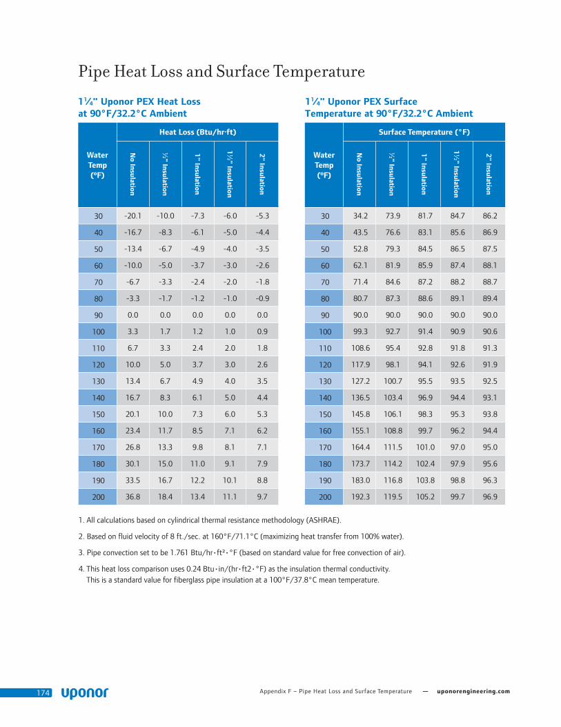
Appendix F – Pipe Heat Loss and Surface Temperature — uponorengineering.com174
Pipe Heat Loss and Surface Temperature
1 1⁄4" Uponor PEX Surface Temperature at 90°F/32.2°C Ambient
Water Temp (ºF)
Surface Temperature (°F)
No Insulation
½" Insulation
1" Insulation
1½" Insulation
2" Insulation
30 34.2 73.9 81.7 84.7 86.2
40 43.5 76.6 83.1 85.6 86.9
50 52.8 79.3 84.5 86.5 87.5
60 62.1 81.9 85.9 87.4 88.1
70 71.4 84.6 87.2 88.2 88.7
80 80.7 87.3 88.6 89.1 89.4
90 90.0 90.0 90.0 90.0 90.0
100 99.3 92.7 91.4 90.9 90.6
110 108.6 95.4 92.8 91.8 91.3
120 117.9 98.1 94.1 92.6 91.9
130 127.2 100.7 95.5 93.5 92.5
140 136.5 103.4 96.9 94.4 93.1
150 145.8 106.1 98.3 95.3 93.8
160 155.1 108.8 99.7 96.2 94.4
170 164.4 111.5 101.0 97.0 95.0
180 173.7 114.2 102.4 97.9 95.6
190 183.0 116.8 103.8 98.8 96.3
200 192.3 119.5 105.2 99.7 96.9
1 1⁄4" Uponor PEX Heat Loss at 90°F/32.2°C Ambient
Water Temp (ºF)
Heat Loss (Btu/hr·ft)
No Insulation
½" Insulation
1" Insulation
1½" Insulation
2" Insulation
30 -20.1 -10.0 -7.3 -6.0 -5.3
40 -16.7 -8.3 -6.1 -5.0 -4.4
50 -13.4 -6.7 -4.9 -4.0 -3.5
60 -10.0 -5.0 -3.7 -3.0 -2.6
70 -6.7 -3.3 -2.4 -2.0 -1.8
80 -3.3 -1.7 -1.2 -1.0 -0.9
90 0.0 0.0 0.0 0.0 0.0
100 3.3 1.7 1.2 1.0 0.9
110 6.7 3.3 2.4 2.0 1.8
120 10.0 5.0 3.7 3.0 2.6
130 13.4 6.7 4.9 4.0 3.5
140 16.7 8.3 6.1 5.0 4.4
150 20.1 10.0 7.3 6.0 5.3
160 23.4 11.7 8.5 7.1 6.2
170 26.8 13.3 9.8 8.1 7.1
180 30.1 15.0 11.0 9.1 7.9
190 33.5 16.7 12.2 10.1 8.8
200 36.8 18.4 13.4 11.1 9.7
1. All calculations based on cylindrical thermal resistance methodology (ASHRAE).
2. Based on fluid velocity of 8 ft./sec. at 160°F/71.1°C (maximizing heat transfer from 100% water).
3. Pipe convection set to be 1.761 Btu/hr•ft²•°F (based on standard value for free convection of air).
4. This heat loss comparison uses 0.24 Btu•in/(hr•ft2•°F) as the insulation thermal conductivity. This is a standard value for fiberglass pipe insulation at a 100°F/37.8°C mean temperature.

Plumbing Design Assistance Manual — Appendix F – Pipe Heat Loss and Surface Temperature 175
Pipe Heat Loss and Surface Temperature
1 1⁄2" Uponor PEX Surface Temperature at 90°F/32.2°C Ambient
Water Temp (ºF)
Surface Temperature (°F)
No Insulation
½" Insulation
1" Insulation
1½" Insulation
2" Insulation
30 34.9 73.6 81.4 84.5 86.1
40 44.1 76.3 82.9 85.4 86.7
50 53.3 79.1 84.3 86.3 87.4
60 62.5 81.8 85.7 87.3 88.0
70 71.6 84.5 87.1 88.2 88.7
80 80.8 87.3 88.6 89.1 89.3
90 90.0 90.0 90.0 90.0 90.0
100 99.2 92.7 91.4 90.9 90.7
110 108.4 95.5 92.9 91.8 91.3
120 117.5 98.2 94.3 92.7 92.0
130 126.7 100.9 95.7 93.7 92.6
140 135.9 103.7 97.1 94.6 93.3
150 145.1 106.4 98.6 95.5 93.9
160 154.2 109.1 100.0 96.4 94.6
170 163.4 111.8 101.4 97.3 95.2
180 172.6 114.6 102.8 98.2 95.9
190 181.8 117.3 104.3 99.1 96.5
200 191.0 120.0 105.7 100.1 97.2
1 1⁄2" Uponor PEX Heat Loss at 90°F/32.2°C Ambient
Water Temp (ºF)
Heat Loss (Btu/hr·ft)
No Insulation
½" Insulation
1" Insulation
1½" Insulation
2" Insulation
30 -23.4 -11.3 -8.1 -6.6 -5.8
40 -19.5 -9.4 -6.8 -5.5 -4.8
50 -15.6 -7.5 -5.4 -4.4 -3.9
60 -11.7 -5.6 -4.1 -3.3 -2.9
70 -7.8 -3.8 -2.7 -2.2 -1.9
80 -3.9 -1.9 -1.4 -1.1 -1.0
90 0.0 0.0 0.0 0.0 0.0
100 3.9 1.9 1.4 1.1 1.0
110 7.8 3.8 2.7 2.2 1.9
120 11.7 5.6 4.1 3.3 2.9
130 15.6 7.5 5.4 4.4 3.9
140 19.5 9.4 6.8 5.5 4.8
150 23.4 11.3 8.1 6.6 5.8
160 27.3 13.1 9.5 7.8 6.7
170 31.2 15.0 10.8 8.9 7.7
180 35.1 16.9 12.2 10.0 8.7
190 39.0 18.8 13.5 11.1 9.6
200 43.0 20.6 14.9 12.2 10.6
1. All calculations based on cylindrical thermal resistance methodology (ASHRAE).
2. Based on fluid velocity of 8 ft./sec. at 160°F/71.1°C (maximizing heat transfer from 100% water).
3. Pipe convection set to be 1.761 Btu/hr•ft²•°F (based on standard value for free convection of air).
4. This heat loss comparison uses 0.24 Btu•in/(hr•ft2•°F) as the insulation thermal conductivity. This is a standard value for fiberglass pipe insulation at a 100°F/37.8°C mean temperature.

Appendix F – Pipe Heat Loss and Surface Temperature — uponorengineering.com176
Pipe Heat Loss and Surface Temperature
2" Uponor PEX Surface Temperature at 90°F/32.2°C Ambient
Water Temp (ºF)
Surface Temperature (°F)
No Insulation
½" Insulation
1" Insulation
1½" Insulation
2" Insulation
30 36.3 73.2 81.0 84.2 85.8
40 45.2 76.0 82.5 85.1 86.5
50 54.2 78.8 84.0 86.1 87.2
60 63.1 81.6 85.5 87.1 87.9
70 72.1 84.4 87.0 88.1 88.6
80 81.0 87.2 88.5 89.0 89.3
90 90.0 90.0 90.0 90.0 90.0
100 99.0 92.8 91.5 91.0 90.7
110 107.9 95.6 93.0 91.9 91.4
120 116.9 98.4 94.5 92.9 92.1
130 125.8 101.2 96.0 93.9 92.8
140 134.8 104.0 97.5 94.9 93.5
150 143.7 106.8 99.0 95.8 94.2
160 152.7 109.5 100.5 96.8 94.9
170 161.7 112.3 101.9 97.8 95.6
180 170.6 115.1 103.4 98.7 96.3
190 179.6 117.9 104.9 99.7 97.0
200 188.5 120.7 106.4 100.7 97.7
2" Uponor PEX Heat Loss at 90°F/32.2°C Ambient
Water Temp (ºF)
Heat Loss (Btu/hr·ft)
No Insulation
½" Insulation
1" Insulation
1½" Insulation
2" Insulation
30 -29.9 -13.7 -9.7 -7.8 -6.7
40 -24.9 -11.4 -8.1 -6.5 -5.6
50 -19.9 -9.1 -6.4 -5.2 -4.5
60 -14.9 -6.9 -4.8 -3.9 -3.4
70 -10.0 -4.6 -3.2 -2.6 -2.2
80 -5.0 -2.3 -1.6 -1.3 -1.1
90 0.0 0.0 0.0 0.0 0.0
100 5.0 2.3 1.6 1.3 1.1
110 10.0 4.6 3.2 2.6 2.2
120 14.9 6.9 4.8 3.9 3.4
130 19.9 9.1 6.4 5.2 4.5
140 24.9 11.4 8.1 6.5 5.6
150 29.9 13.7 9.7 7.8 6.7
160 34.9 16.0 11.3 9.1 7.8
170 39.9 18.3 12.9 10.4 9.0
180 44.8 20.6 14.5 11.7 10.1
190 49.8 22.8 16.1 13.0 11.2
200 54.8 25.1 17.7 14.3 12.3
1. All calculations based on cylindrical thermal resistance methodology (ASHRAE).
2. Based on fluid velocity of 8 ft./sec. at 160°F/71.1°C (maximizing heat transfer from 100% water).
3. Pipe convection set to be 1.761 Btu/hr•ft²•°F (based on standard value for free convection of air).
4. This heat loss comparison uses 0.24 Btu•in/(hr•ft2•°F) as the insulation thermal conductivity. This is a standard value for fiberglass pipe insulation at a 100°F/37.8°C mean temperature.

Plumbing Design Assistance Manual — Appendix F – Pipe Heat Loss and Surface Temperature 177
Pipe Heat Loss and Surface Temperature
2 1⁄2" Uponor PEX Surface Temperature at 90°F/32.2°C Ambient
Water Temp (ºF)
Surface Temperature (°F)
No Insulation
½" Insulation
1" Insulation
1½" Insulation
2" Insulation
30 37.6 73.0 80.8 83.9 85.6
40 46.3 75.9 82.3 84.9 86.3
50 55.0 78.7 83.8 86.0 87.1
60 63.8 81.5 85.4 87.0 87.8
70 72.5 84.3 86.9 88.0 88.5
80 81.3 87.2 88.5 89.0 89.3
90 90.0 90.0 90.0 90.0 90.0
100 98.7 92.8 91.5 91.0 90.7
110 107.5 95.7 93.1 92.0 91.5
120 116.2 98.5 94.6 93.0 92.2
130 125.0 101.3 96.2 94.0 92.9
140 133.7 104.1 97.7 95.1 93.7
150 142.4 107.0 99.2 96.1 94.4
160 151.2 109.8 100.8 97.1 95.1
170 159.9 112.6 102.3 98.1 95.9
180 168.7 115.4 103.9 99.1 96.6
190 177.4 118.3 105.4 100.1 97.3
200 186.1 121.1 106.9 101.1 98.1
2 1⁄2" Uponor PEX Heat Loss at 90°F/32.2°C Ambient
Water Temp (ºF)
Heat Loss (Btu/hr·ft)
No Insulation
½" Insulation
1" Insulation
1½" Insulation
2" Insulation
30 -36.0 -16.1 -11.2 -8.9 -7.6
40 -30.0 -13.4 -9.3 -7.5 -6.4
50 -24.0 -10.7 -7.5 -6.0 -5.1
60 -18.0 -8.0 -5.6 -4.5 -3.8
70 -12.0 -5.4 -3.7 -3.0 -2.5
80 -6.0 -2.7 -1.9 -1.5 -1.3
90 0.0 0.0 0.0 0.0 0.0
100 6.0 2.7 1.9 1.5 1.3
110 12.0 5.4 3.7 3.0 2.5
120 18.0 8.0 5.6 4.5 3.8
130 24.0 10.7 7.5 6.0 5.1
140 30.0 13.4 9.3 7.5 6.4
150 36.0 16.1 11.2 8.9 7.6
160 42.0 18.8 13.1 10.4 8.9
170 48.0 21.5 14.9 11.9 10.2
180 54.1 24.1 16.8 13.4 11.5
190 60.1 26.8 18.6 14.9 12.7
200 66.1 29.5 20.5 16.4 14.0
1. All calculations based on cylindrical thermal resistance methodology (ASHRAE).
2. Based on fluid velocity of 8 ft./sec. at 160°F/71.1°C (maximizing heat transfer from 100% water).
3. Pipe convection set to be 1.761 Btu/hr•ft²•°F (based on standard value for free convection of air).
4. This heat loss comparison uses 0.24 Btu•in/(hr•ft2•°F) as the insulation thermal conductivity. This is a standard value for fiberglass pipe insulation at a 100°F/37.8°C mean temperature.

Appendix F – Pipe Heat Loss and Surface Temperature — uponorengineering.com178
Pipe Heat Loss and Surface Temperature
3" Uponor PEX Surface Temperature at 90°F/32.2°C Ambient
Water Temp (ºF)
Surface Temperature (°F)
No Insulation
½" Insulation
1" Insulation
1½" Insulation
2" Insulation
30 38.7 72.9 80.6 83.7 85.4
40 47.3 75.8 82.1 84.8 86.2
50 55.8 78.6 83.7 85.8 87.0
60 64.4 81.5 85.3 86.9 87.7
70 72.9 84.3 86.9 87.9 88.5
80 81.5 87.2 88.4 89.0 89.2
90 90.0 90.0 90.0 90.0 90.0
100 98.5 92.8 91.6 91.0 90.8
110 107.1 95.7 93.1 92.1 91.5
120 115.6 98.5 94.7 93.1 92.3
130 124.2 101.4 96.3 94.2 93.0
140 132.7 104.2 97.9 95.2 93.8
150 141.3 107.1 99.4 96.3 94.6
160 149.8 109.9 101.0 97.3 95.3
170 158.3 112.8 102.6 98.4 96.1
180 166.9 115.6 104.2 99.4 96.9
190 175.4 118.4 105.7 100.4 97.6
200 184.0 121.3 107.3 101.5 98.4
3" Uponor PEX-a Heat Loss at 90°F/32.2°C Ambient
Water Temp (ºF)
Heat Loss (Btu/hr·ft)
No Insulation
½" Insulation
1" Insulation
1½" Insulation
2" Insulation
30 -41.9 -18.4 -12.7 -10.0 -8.5
40 -34.9 -15.4 -10.6 -8.4 -7.1
50 -28.0 -12.3 -8.5 -6.7 -5.7
60 -21.0 -9.2 -6.3 -5.0 -4.3
70 -14.0 -6.1 -4.2 -3.3 -2.8
80 -7.0 -3.1 -2.1 -1.7 -1.4
90 0.0 0.0 0.0 0.0 0.0
100 7.0 3.1 2.1 1.7 1.4
110 14.0 6.1 4.2 3.3 2.8
120 21.0 9.2 6.3 5.0 4.3
130 28.0 12.3 8.5 6.7 5.7
140 34.9 15.4 10.6 8.4 7.1
150 41.9 18.4 12.7 10.0 8.5
160 48.9 21.5 14.8 11.7 9.9
170 55.9 24.6 16.9 13.4 11.4
180 62.9 27.6 19.0 15.1 12.8
190 69.9 30.7 21.1 16.7 14.2
200 76.9 33.8 23.2 18.4 15.6
1. All calculations based on cylindrical thermal resistance methodology (ASHRAE).
2. Based on fluid velocity of 8 ft./sec. at 160°F/71.1°C (maximizing heat transfer from 100% water).
3. Pipe convection set to be 1.761 Btu/hr•ft²•°F (based on standard value for free convection of air).
4. This heat loss comparison uses 0.24 Btu•in/(hr•ft2•°F) as the insulation thermal conductivity. This is a standard value for fiberglass pipe insulation at a 100°F/37.8°C mean temperature.

179Plumbing Design Assistance Manual

0_PD
AM
_Man
ual_
6867
4_11
15_c
ov-f
orw
ard,
Cop
yrig
ht ©
201
5 U
pono
r, Pr
inte
d in
the
Uni
ted
Stat
es
Uponor, Inc. 5925 148th Street West Apple Valley, MN 55124 USA Tel: 800.321.4739 Fax: 952.891.2008
Uponor Ltd. 2000 Argentia Rd., Plaza 1, Ste. 200 Mississauga, ON L5N 1W1 CANADA Tel: 888.994.7726 Fax: 800.638.9517
uponorengineering.com

Plum
bing Design A
ssistance Manual (P
DA
M)
Fourth Edition