overview and comparison of grid harmonics and conducted … · 2017-07-06 · overview and...
TRANSCRIPT

© 2012 Mesago PCIM GmbH
Proceedings of the first Power Electronics South America 2012 Conference and Exhibition (PCIM 2012), South America, SaõPaulo, Brazil, September 11-13, 2012
Overview and Comparison of Grid Harmonics and Conducted EMI Standards for LV ConvertersConnected to the MV Distribution System
R. Burkart,J. W. Kolar
This material is published in order to provide access to research results of the Power Electronic Systems Laboratory / D-ITET / ETH Zurich. Internal or personal use of this material is permitted. However, permission to reprint/republish this material for advertising or promotional purposes or for creating new collective works for resale or redistribution must be obtained from the copyright holder. By choosing to view this document, you agree to all provisions of the copyright laws protecting it.

Overview and Comparison of Grid Harmonics and Conducted EMI Standards forLV Converters Connected to the MV Distribution System
Ralph Burkart and Johann W. Kolar
Power Electronic Systems Laboratory, ETH Zurich, Switzerland, burkart,[email protected]
Abstract
Grid harmonics and conducted EMI standards pose fundamental constraints on the design and opti-mization of commercial and industrial power electronics systems. The aim of this paper is to providean overview of different such standards which apply to converter modules in non-public low voltagegrids connected to the medium voltage distribution system. The examinations cover the IEEE 519,IEEE 1547, and CISPR 11 standards as well as the technical guideline “Generating Plants Connectedto the Medium-Voltage Network” from BDEW. In a second step, a comparative analysis is performedwhich identifies the most stringent limits in the considered frequency range from 100 Hz to 30 MHz. Theanalysis shows that BDEW generally defines the lowest limits for frequencies below 9 kHz, whereas forfrequencies higher than 150 kHz the most difficult standard to comply with is CISPR 11. Additional limitsare proposed for frequencies between 9 kHz and 150 kHz for which currently no applicable standardsexist.
1 Introduction
A fundamental requirement of commercial and industrial power electronics systems is the compliancewith grid harmonics and conducted EMI standards. In medium voltage (MV) distribution systems, typicalloads are low voltage (LV) converter systems (e.g. wind farms, factories) comprising a multitude ofindividual (possibly low power) consuming and/or generating LV converter modules as shown in Fig.1(a). In contrast to LV grid harmonics standards which are often defined for individual modules (e.g.IEC 61000-3-12 [1]), the MV standards are mostly defined for the point of common coupling (PCC, see[2] for a detailed definition) and hence for the overall converter system. From the design point of view,it is hence of interest what limits the individual modules must comply with in order to guarantee overallsystem compliance at the PCC. In this paper, an overview of MV grid harmonics standards is given.Based on these standards, limits for the individual modules are derived. Conducted EMI standards,which typically apply to the individual modules and to higher frequencies (Fig. 1(b)), are included intothe analysis as they are relevant for the proper functioning of the converter system. In a second step,the standards are compared to each other to identify the most stringent limits in the frequency rangefrom 100 Hz to 30 MHz.
Section 2 gives a short summary of the standards considered in this paper. In Section 3, the compar-ative analysis of the investigated standards is performed. Finally, Section 4 gives a practical example.RMS currents and RMS line-to-line voltages are assumed throughout this paper. If not otherwise stated,SI units are used.
PCC
MV
dis
tribu
tion
syst
em
LV converter system
LV c
onve
rter
mod
ules
GH Standards EMI Standards
Frequency
Lim
its
(a) (b)
GH Standards
EMI Standards
Fig. 1: Power consuming and generating converter modules in a LV converter system connected tothe MV distribution system at the PCC (a). Relationship between MV grid harmonics (GH) and EMIstandards (b).
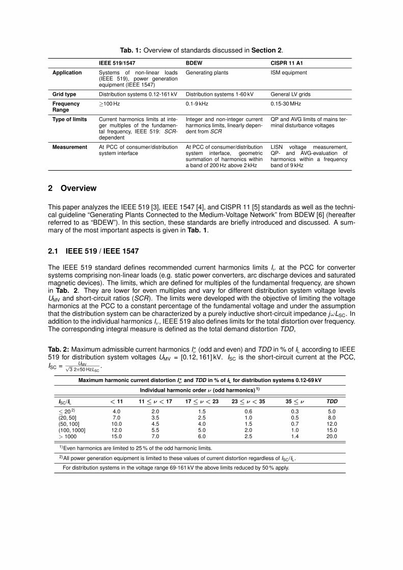
Tab. 1: Overview of standards discussed in Section 2.
IEEE 519/1547 BDEW CISPR 11 A1
Application Systems of non-linear loads(IEEE 519), power generationequipment (IEEE 1547)
Generating plants ISM equipment
Grid type Distribution systems 0.12-161 kV Distribution systems 1-60 kV General LV grids
FrequencyRange
≥100 Hz 0.1-9 kHz 0.15-30 MHz
Type of limits Current harmonics limits at inte-ger multiples of the fundamen-tal frequency, IEEE 519: SCR-dependent
Integer and non-integer currentharmonics limits, linearly depen-dent from SCR
QP and AVG limits of mains ter-minal disturbance voltages
Measurement At PCC of consumer/distributionsystem interface
At PCC of consumer/distributionsystem interface, geometricsummation of harmonics withina band of 200 Hz above 2 kHz
LISN voltage measurement,QP- and AVG-evaluation ofharmonics within a frequencyband of 9 kHz
2 Overview
This paper analyzes the IEEE 519 [3], IEEE 1547 [4], and CISPR 11 [5] standards as well as the techni-cal guideline “Generating Plants Connected to the Medium-Voltage Network” from BDEW [6] (hereafterreferred to as “BDEW”). In this section, these standards are briefly introduced and discussed. A sum-mary of the most important aspects is given in Tab. 1.
2.1 IEEE 519 / IEEE 1547
The IEEE 519 standard defines recommended current harmonics limits Iν at the PCC for convertersystems comprising non-linear loads (e.g. static power converters, arc discharge devices and saturatedmagnetic devices). The limits, which are defined for multiples of the fundamental frequency, are shownin Tab. 2. They are lower for even multiples and vary for different distribution system voltage levelsUMV and short-circuit ratios (SCR). The limits were developed with the objective of limiting the voltageharmonics at the PCC to a constant percentage of the fundamental voltage and under the assumptionthat the distribution system can be characterized by a purely inductive short-circuit impedance jωLSC. Inaddition to the individual harmonics Iν , IEEE 519 also defines limits for the total distortion over frequency.The corresponding integral measure is defined as the total demand distortion TDD,
Tab. 2: Maximum admissible current harmonics I?ν (odd and even) and TDD in % of IL according to IEEE519 for distribution system voltages UMV = [0.12, 161] kV. ISC is the short-circuit current at the PCC,ISC = UMV√
3 2π50 HzLSC.
Maximum harmonic current distortion I?ν and TDD in % of IL for distribution systems 0.12-69 kV
Individual harmonic order ν (odd harmonics) 1)
ISC/IL < 11 11 ≤ ν < 17 17 ≤ ν < 23 23 ≤ ν < 35 35 ≤ ν TDD
≤ 20 2) 4.0 2.0 1.5 0.6 0.3 5.0(20, 50] 7.0 3.5 2.5 1.0 0.5 8.0(50, 100] 10.0 4.5 4.0 1.5 0.7 12.0(100, 1000] 12.0 5.5 5.0 2.0 1.0 15.0> 1000 15.0 7.0 6.0 2.5 1.4 20.0
1)Even harmonics are limited to 25 % of the odd harmonic limits.2)All power generation equipment is limited to these values of current distortion regardless of ISC/IL.
For distribution systems in the voltage range 69-161 kV the above limits reduced by 50 % apply.
TDD =
√∑∞ν=2 I2
dist,ν
IL, (1)
where IL is the maximum fundamental load current and Idist,ν the generated current harmonics of theconverter system at the PCC.
The IEEE 1547 standard applies to power generation equipment. Its limits are derived from to the IEEE519 limits for SCR ≤ 20 (Tab. 2) and are independent from SCR.
2.2 BDEW
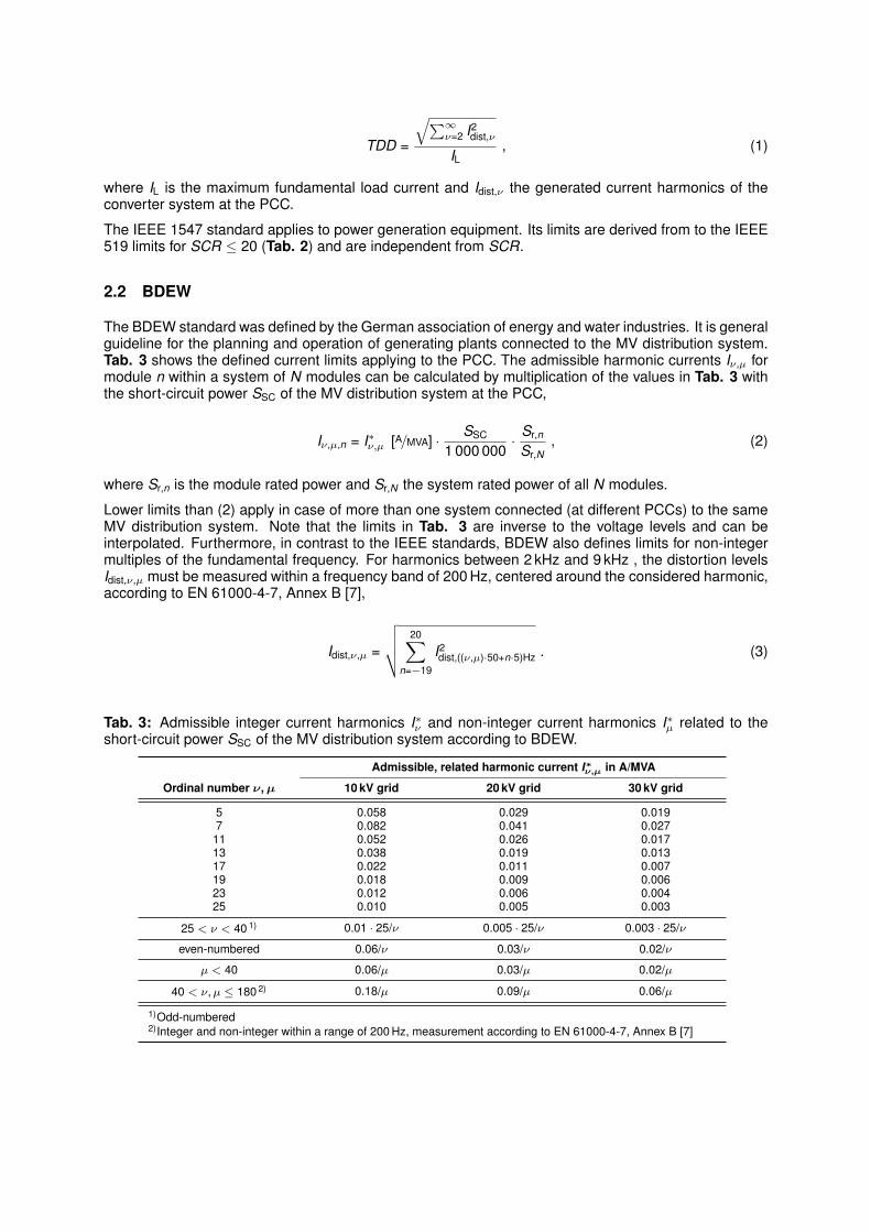
The BDEW standard was defined by the German association of energy and water industries. It is generalguideline for the planning and operation of generating plants connected to the MV distribution system.Tab. 3 shows the defined current limits applying to the PCC. The admissible harmonic currents Iν,µ formodule n within a system of N modules can be calculated by multiplication of the values in Tab. 3 withthe short-circuit power SSC of the MV distribution system at the PCC,
Iν,µ,n = I∗ν,µ [A/MVA] ·SSC
1 000 000· Sr,n
Sr,N, (2)
where Sr,n is the module rated power and Sr,N the system rated power of all N modules.
Lower limits than (2) apply in case of more than one system connected (at different PCCs) to the sameMV distribution system. Note that the limits in Tab. 3 are inverse to the voltage levels and can beinterpolated. Furthermore, in contrast to the IEEE standards, BDEW also defines limits for non-integermultiples of the fundamental frequency. For harmonics between 2 kHz and 9 kHz , the distortion levelsIdist,ν,µ must be measured within a frequency band of 200 Hz, centered around the considered harmonic,according to EN 61000-4-7, Annex B [7],
Idist,ν,µ =
√√√√ 20∑n=−19
I2dist,((ν,µ)·50+n·5)Hz . (3)
Tab. 3: Admissible integer current harmonics I∗ν and non-integer current harmonics I∗µ related to theshort-circuit power SSC of the MV distribution system according to BDEW.
Admissible, related harmonic current I∗ν,µ in A/MVA
Ordinal number ν,µ 10 kV grid 20 kV grid 30 kV grid
5 0.058 0.029 0.0197 0.082 0.041 0.027
11 0.052 0.026 0.01713 0.038 0.019 0.01317 0.022 0.011 0.00719 0.018 0.009 0.00623 0.012 0.006 0.00425 0.010 0.005 0.003
25 < ν < 40 1) 0.01 · 25/ν 0.005 · 25/ν 0.003 · 25/ν
even-numbered 0.06/ν 0.03/ν 0.02/ν
µ < 40 0.06/µ 0.03/µ 0.02/µ
40 < ν,µ ≤ 180 2) 0.18/µ 0.09/µ 0.06/µ
1)Odd-numbered2)Integer and non-integer within a range of 200 Hz, measurement according to EN 61000-4-7, Annex B [7]

Tab. 4: CISPR 11 limits UCISPR for class A group 1 (A1) equipment. Sr is the rated module power, Ir themodule rated phase currents and “IT grid” refers to isolated neutral or high impedance earthed grids asdefined in IEC 60364-1 [13].
Mains terminal disturbance voltage limits UCISPR for A1 equipment in dB(µV)
Sr ≤ 20 kVA Sr > 20 kVA 2) Sr ≤ 75 kVA, IT grid 3)
Frequency (MHz) 1) QP AVG QP AVG QP AVG
0.15-0.5 79 66 100 90 130 1200.5-5 73 60 86 76 125 1155-30 73 60 90-73 4) 80-60 4) 115 105
1)At the transition frequency, the more stringent limit shall apply.2)Limits equivalent to: CISPR 11 A2, Sr ≤ 20 kVA; IEC 61800-3 C3, Ir ≤ 100 A; IEC 62040-2 C3, Ir = (16, 100] A3)Limits equivalent to: CISPR 11 A2, Sr > 20 kVA; IEC 61800-3 C3, Ir > 100 A; IEC 62040-2 C3, Ir > 100 A4)Decreasing linearly with logarithm of frequency
a
b
c
L1
L2
L3
2L 1L
1C2C3C
1R2R
Three-phase LISN
50 Ω terminations
To test receiver
HF currents LF currents
DUT
Fig. 2: Typical realization of a three-phase LISN according to CISPR 16 [8]. L1, L2, C1, C2, R1 and R2form a bidirectional filter. It defines a stable impedance seen from the DUT and filters incoming griddisturbances. High-frequency (HF) emissions from the DUT are coupled to the test receiver, whereasthe low-frequency (LF) currents can flow between the grid and DUT.
2.3 CISPR 11
CISPR 11 defines limits for conducted emissions (CE) in the frequency range 0.15-30 MHz for industrial,scientific and medical (ISM) devices. In contrast to the IEEE standards and BDEW, CISPR 11 is aLV standard applying to individual converter modules. The emissions must be measured by meansof a line impedance stabilization network (LISN) which is placed between the device under test (DUT)and the LV grid (Fig. 2). In the relevant frequency range, the LISN features a defined impedance ofZLISN ≈ 50Ω between phases and ground [8]. A test receiver is used to measure the emissions acrossthat impedance. The associated harmonics inside a moving frequency band of 9 kHz, centered aroundthe analyzed frequency, are then processed either by means of an average (AVG) or quasi-peak (QP)detector, which both show non-linear input-output characteristics. However, both are tuned so as toindicate the RMS value in case of only a single harmonic within the frequency band. The interestedreader is referred to [5, 8, 9] for more detailed information.
Tab. 4 shows the emission limits UCISPR of class A group 1 (A1) equipment, which includes amongst oth-ers semiconductor power converters in commercial and industrial environments. Note that the genericCISPR 11 class A limits are identical to the device specific limits in IEC 61000-6-4 (industrial equipment)[10] and to those of IEC 62040-2 (UPS systems) [11] and IEC 61800-3 (adjustable speed electricalpower drive systems) [12] for category C3 (industrial environment) equipment.
3 Comparison
In this section, based on the investigated standards, limits are derived which can be applied to anindividual converter module. The limits should guarantee overall system compliance, provided that allmodules comply with these limits. Furthermore, a comparative analysis of the derived limits is performed

DUTPCC
LISN
IEEEIBDEW′I BDEWICISPRI
SCR=20S =10,50 kVAr
IEEEI′
U =0.4kVLV U =10kVMV
f 1 kHz s>
Fig. 3: Setup for comparison of standards and derivation of module-based limits. The converter module(DUT), either in a grounded or isolated IT LV grid, is connected to the MV distribution system by meansof a transformer. The depicted currents denote the calculated admissible current harmonics.
in order to identify the most stringent standards in the frequency range from 100 Hz to 30 MHz. Switchedconverter modules with switching frequencies fs in the kilo-Hertz range are considered.
3.1 Methodology
Although the IEEE and BDEW limits are formulated for the PCC and hence for converter systems thatpossibly consist of more than one module, equivalent limits can be calculated which can be applied tothe individual modules of the system. The translation from PCC-based limits to individual module-basedlimits requires, however, that the SCR at the PCC is given (see (2) and Tab. 2). Consequently, for thepurpose of this comparison, a worst-case short-circuit ratio of SCR = 20 has been assumed. A setup ofan individual module in a LV converter system (ULV = 0.4 kV) connected to the MV distribution system(UMV = 10 kV) has been considered (Fig. 3).
3.1.1 Equivalent IEEE 519/1547 Limits
The equivalent IEEE 519/1547 admissible current harmonics I′IEEE for an individual converter module onthe LV secondary side of the transformer can be calculated by
I′IEEE =c · IIEEE = c · I?ν |SCR = 20 [%] · IL = c · I?ν |SCR = 20 [%] ·Irc
= I?ν |SCR = 20 [%] · Ir , (4)
where an idealized transformer with turns ratio c = UMVULV
has been assumed and Ir is the module ratedphase current. The TDD limits will not be considered in this comparison.
3.1.2 Equivalent BDEW Limits
The equivalent current limits I′BDEW according to BDEW can be calculated using (2),
I′BDEW =c · IBDEW = c · I∗µ,ν
∣∣10 kV
[A/MVA] ·SSC
1 000 000· Sr,n
Sr,N= c · I∗µ,ν
∣∣10 kV
[A/MVA] ·SCR
1 000 000·√
3UMV ·Irc
(5)
= I∗µ,ν
∣∣10 kV
[A/MVA] ·SCR
1 000 000·√
3UMV · Ir , (6)
Equation (6) is valid for single harmonics. However, BDEW considers a measurement band of 200 Hzfor frequencies above 2 kHz (3), which may include multiple harmonics. Therefore, for the purpose ofa more meaningful comparison, the typical sidebands at multiples of fs of switched converter systems(see Fig. 6(a)) will be accounted for by reducing I∗ν,µ
∣∣10 kV
in (6) by a factor√
2 (3 dB).

3.1.3 Equivalent CISPR 11 Limits
The CISPR 11 equivalent admissible current harmonics ICISPR can be computed by means of the LISNimpedance ZLISN,
ICISPR =10
UCISPR [dB(µV)]20 · 10−6 VZLISN
. (7)
Again, (7) is only meaningful in case of a single harmonic within the corresponding CISPR measurementband of 9 kHz. In case of multiple harmonics, it is not sufficient to guarantee (7) for all individual har-monics as the QP and AVG detectors will indicate higher emission levels [9]. Hence, UCISPR in (7) will bereduced by 15 dB(µV), which is the worst case difference between the individual harmonics and corre-sponding AVG emission levels observed in simulations of various 2- and 3-level voltage source inverter(VSI) topologies with sinusoidal PWM and fs > 1 kHz. Moreover, only AVG limits will be considered asthey are generally more stringent than QP limits. This is due to the similar sensitivity of the QP andAVG detector type for switching frequencies in the kilo-Hertz range ([14], Fig. 6(c))and the lower AVGemission limits (Tab. 4). Finally, in contrast to (4) and (6), (7) does not depend on SCR but on Sr andthe grounding conditions of the LV grid. Therefore, a converter with Sr =10 kW in a grounded LV grid aswell a converter with Sr =50 kW in both grounded and isolated IT LV grids have been considered.
3.2 Results
Fig. 4 shows the calculated admissible current harmonics for the considered converter module as shownin Fig. 3 in percent of Ir. Furthermore, reduced BDEW and CISPR limits are depicted as discussed inthe last section in order to allow for a more meaningful comparison between limits based on differentmeasurement frequency bands. It can be seen that for frequencies below 150 kHz, the BDEW standarddefines more stringent limits than the IEEE standards. This holds true for SCRs up to approximately 40,where IEEE 1547 becomes the most stringent standard due to the increasing limits of BDEW and IEEE519 for growing SCRs. For frequencies above 150 kHz, CISPR 11 is clearly more stringent than IEEE,provided that Sr is not too low.
104 105 106 10710-6
103102
10-5
10-4
10-3
10-2
10-1
100
10
Frequency [Hz]
b
cd
a
Adm
issi
ble
curr
ents
[% I
] r
a_
b_
c_
~aIEEE 519/1547BDEWa
bcd
BDEW, extrapolatedCISPR 11 A1 S 50 kVA, IT gridr =AVG
CISPR 11 A1 S 50 kVAr =AVG
CISPR 11 A1 S 10 kVA=rAVG++
+
+ +
d_
a_
~ab_
c_
d_
Fig. 4: Comparison of the investigated standards of Section 2 for SCR = 20, Sr = 10, 50 kW, basedon the setup as shown in Fig. 3 and (4), (6), (7). Squares and circles correspond to limits for discretefrequencies, the lower IEEE 519/1547 and BDEW limits to even order harmonics. The measurementbands of 200 Hz for BDEW (above 2 kHz) and 9 kHz for CISPR 11 have been accounted for by loweringI∗µ,v
∣∣10 kV
in (6) by 3 dB (curve a) and UCISPR in (7) by 15 dB(µV) (curves b, c, d), respectively. Curve arepresents the extrapolated BDEW limits proposed in Section 3.3, which close the currently existinggap of applicable limits from 9 kHz to 150 kHz.
b L2
DMC
a L1boostL DML
c L3U DC
U LV
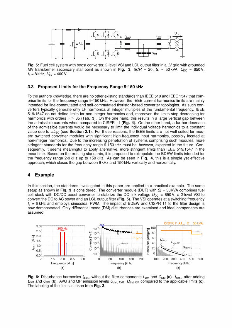
Fig. 5: Fuel cell system with boost converter, 2-level VSI and LCL output filter in a LV grid with groundedMV transformer secondary star point as shown in Fig. 3, SCR = 20, Sr = 50 kVA, UDC = 650 V,fs = 8 kHz, ULV = 400 V.
3.3 Proposed Limits for the Frequency Range 9-150 kHz
To the authors knowledge, there are no other existing standards than IEEE 519 and IEEE 1547 that com-prise limits for the frequency range 9-150 kHz. However, the IEEE current harmonics limits are mainlyintended for line-commutated and self-commutated thyristor-based converter topologies. As such con-verters typically generate only LF harmonics at integer multiples of the fundamental frequency, IEEE519/1547 do not define limits for non-integer harmonics and, moreover, the limits stop decreasing forharmonics with orders ν ≥ 35 (Tab. 3). On the one hand, this results in a large vertical gap betweenthe admissible currents when compared to CISPR 11 (Fig. 4). On the other hand, a further decreaseof the admissible currents would be necessary to limit the individual voltage harmonics to a constantvalue due to ωLSC (see Section 2.1). For these reasons, the IEEE limits are not well suited for mod-ern switched converter modules with significant high-frequency input harmonics, possibly located atnon-integer harmonics. Due to the increasing penetration of systems comprising such modules, morestringent standards for the frequency range 9-150 kHz must be, however, expected in the future. Con-sequently, it seems meaningful to apply alternative, more stringent limits than IEEE 519/1547 in themeantime. Based on the existing standards, it is proposed to extrapolate the BDEW limits intended forthe frequency range 2-9 kHz up to 150 kHz. As can be seen in Fig. 4, this is a simple yet effectiveapproach, which closes the gap between 9 kHz and 150 kHz vertically and horizontally.
4 Example
In this section, the standards investigated in this paper are applied to a practical example. The samesetup as shown in Fig. 3 is considered. The converter module (DUT) with Sr = 50 kVA comprises fuelcell stack with DC/DC boost converter to stabilize the DC-link voltage UDC = 650 V, a 2-level VSI toconvert the DC to AC power and an LCL output filter (Fig. 5). The VSI operates at a switching frequencyfs = 8 kHz and employs sinusoidal PWM. The impact of BDEW and CISPR 11 to the filter design isnow demonstrated. Only differential mode (DM) disturbances are examined and ideal components areassumed.
0.00.51.01.52.02.53.0
Frequency [kHz]
020406080
100
8.0 8.57.5 9.07.0
200 Hz
10-6
10-5
10-4
10-310-2
10-7
Cur
rent
s [%
I ] r
Frequency [kHz]100 15050 2000
Frequency [kHz]300 400200 500100 600
I
[%
I ] r
dist
,
Em
issi
ons
[dB
(μV
)]
c
a a_
~a cc_
(a) (b) (c)
dist,Idist,U
dist,QPU
dist,AVGU
CISPR 11 A1 S 50 kVAr =QP
ν
ν
ν
Fig. 6: Disturbance harmonics Idist,ν without the filter components LDM and CDM (a). Idist,ν after addingLDM and CDM (b). AVG and QP emission levels Udist, AVG, Udist, QP compared to the applicable limits (c).The labeling of the limits is taken from Fig. 3.

In a first, step, the boost inductor is chosen to be Lboost = 0.6 mH in order to guarantee a maximumcurrent ripple of approximately ±10 % of Ir. Neglecting LDM and CDM, the output current harmonics Idist,ν ,which are dominant over Idist,µ, can be obtained by means of simulations. Fig. 6(a) shows the harmonicsaround fs, which are the most critical in terms of damping. Applying BDEW (3) gives Idist,ν,µ ≈ 3.24 %.Comparison with the admissible magnitude of emission in Fig. 4 yields an additional required filterattenuation of a ≈ 0.012 = −38 dB at fs. In order to enable a clean voltage measurement with lowripples of less than ±1 % of ULV, CDM is chosen to be CDM =60 µF. Hence, the required inductance is
LDM =a + 1
a((2πfs)2CDM
) ≈ 0.53 mH . (8)
In Fig. 6(b), the effectiveness of the designed DM filter can be seen. Besides compliance with BDEW,Fig. 6(b) also implies compliance with CISPR 11 as the harmonics at frequencies above 150 kHz arelargely attenuated. This is confirmed by Fig. 6(c) for the considered DM disturbances. Note, however,that for CM disturbances, a more detailed filter design is required, where CISPR 11 becomes relevant.Finally, Fig. 6(c) also confirms that the differences in magnitude between the AVG and QP emissionlevels are only small (see Section 3.1.3).
5 Conclusion
In this paper, different MV grid harmonics and conducted EMI standards were investigated. Based onthese standards, limits applying to LV converter modules in LV converter systems connected to theMV distribution system were derived. A comparative analysis showed that the most stringent limits forfrequencies below 9 kHz and low SCRs is BDEW, whereas for frequencies higher than 150 kHz CISPR11 is the most stringent standard. Furthermore, the investigations found a lack of applicable standardsin the frequency range 9-150 kHz. However, standards covering this frequency range can be expectedin the near future due to the growing deployment of switched converter systems. Meanwhile, it is thusproposed to apply extrapolated BDEW limits as a guideline for the design of converters and its filters.
References
[1] Electromagnetic compatibility (EMC) – Part 3-12: Limits – Limits for harmonic currents produced by equipmentconnected to public low-voltage systems with input current >16 A and ≤75 A per phase, IEC 61000-6-4, 2011.
[2] T. Hoevenaars, K. LeDoux, and M. Colosino, “Interpreting IEEE STD 519 and meeting its harmonic limits inVFD applications,” in Petroleum and Chemical Industry Conference, 2003. Record of Conference Papers. IEEEIndustry Applications Society 50th Annual, sept. 2003, pp. 145 – 150.
[3] Recommended Practices and Requirements for Harmonic Control in Electrical Power Systems, IEEE 519,1992.
[4] Standard for Interconnecting Distributed Resources with Electric Power Systems, IEEE 1547, 2008.[5] Industrial, Scientific and Medical (ISM) Radio-Frequency Equipment – Electromagnetic Disturbance – Charac-
teristics Limits and Methods of Measurement, CISPR 11, 2009.[6] Technical Guideline Generating Plants Connected to the Medium-Voltage Network, BDEW Std., 2008.[7] Electromagnetic compatibility (EMC) – Part 4-7: Testing and measurement techniques – General guide on
harmonics and interharmonics measurements and instrumentation, for power supply systems and equipmentconnected thereto, IEC 61000-4-7, 2008.
[8] Specification for Radio Disturbance and Immunity Measuring Apparatus and Methods, CISPR 16, 2010.[9] M. L. Heldwein, “EMC Filtering of Three-Phase PWM Converters,” Ph.D. dissertation, ETH Zurich, 2007.
[10] Electromagnetic compatibility (EMC) – Part 6-4: Generic standards – Emission standard for industrial environ-ments, IEC 61000-6-4, 2006.
[11] Uninterruptible power systems (UPS) – Part 2: Electromagnetic compatibility (EMC) requirements, IEC 62040-2, 2005.
[12] Adjustable speed electrical power drive systems – Part 3: EMC requirements and specific test methods, IEC61800-3, 2004.
[13] Low-voltage electrical installations – Part 1: Fundamental principles, assessment of general characteristics,definitions, IEC 60364-1, 2005.
[14] J. S. Wilson et al., Test and Measurement. Elsevier Science & Technology, 2009.