otes - fire-lite alarmson intermediate chassis connect a 13 pin jumper cable from 13a to adjacent...
TRANSCRIPT


OTES:

NOTES:1. Detection loop specificationsOperation:
Class A or Class 8 for MCB-108. MZB 4. MZB-8. MZB12 and Class 8 only on MCB-114. MZB-22.Voltage, standby: 23VDC, 60 mV p-p
Current required to ensure alarm: 15mA minimumShort circuit current: 55 ma msxSupervision current: 5maEnd of line resistor: 4.7K, 5%Maximum resistance per side: 100 OhmsMaximum total zone resistance: 100 Ohms
2. Compatible. U.L. listed. 2 wire detector availablefrom fire-Lite, include the following series:
See appendix A
3. Initiating Devices include: Manual itation. heat detectors. smoke detectors. ionization detectors. waterf lowalarm devices. coded manual stations.

4. Inhibit latching circuit by removing diode marked with a 0 from zone card if coded manual stations are con-nected to it zone .
5. Use model WFC If the local authority having jurisdiction requires waterflow service without a disable capabil-ity.
6. Smoke and Ionization detectors requiring separate 24VDC power can be powered from master control boardTerminal 24 (-) and Terminal 35 (+). See table I for current limitations. Use end of line relay (SDLR-8) to super-vise power circuit wiring.
7. Caution is advised when using 2 wire detector containing supplementary relays or Indicators since their opera-tion canr be ensured. Example: activation of a manual station. heat detector. or other shorting type detector willshunt operating current from the 2 wire detectors on the same zone thereby preventing their operation.
8. Detector loop current is sufficient to ensure the alarming of one detector per zone.
9. Detector loop is & Power limited circuit. which may be connected to limited energy cable.
10. Compatible four wire detectos available from Fire-Lite include SD34-24. CP-715.
FIGURE 8-SHUNT TYPE- MUNICIPAL BOX CONNECTIONS

NOTES:
1. The shunt connection is recognized only as a supplementary signalling unit as part of a local control un;t and isnot recognized as an auxiliary control unit connection per NFPA Number 728.
2. Connect master control board terminal 20 & 21 in shunt (parallel) with municipal box trip coil.
3. If box is equipped with a reset supervisory switch, connect switch as follows:A.. Coffnon to TMM-3 Terminal 1B. Normally closed to TMM-3 Terminal 3C. Normally open to TMM-3 Terminal 4
FIGURE 9 -TRANSMITTER MODULE (TMM-3)NOTES:
1. Local Energy Municipal Box (Supervised Circuit)
A. When a local energy municipal box is to be employed. remove the lk, 1/2W resistor from terminals 1 and 2. If the box is equipped with a reset supervisory switch. remove the jumper between terminals 1 and 3.
B. Connect the auxiliary trip coil to terminals 1 and 2.
C. Nominal trip coil characteristics should be:
1. Trip current . 0.25 Amperes2. Coil voltage . 3.65VDC

3. Coil resistance - 14.6 OHMSD. Limit the total interconnecting wire resistance between panel and trip coil to 5 OHMS.
E. Connect the reset supervisory switch as follows: 1. Switch common to Terminal 1
2. Normally closed contact to Terminal 33. Normally open contact to Terminal 4
F. Wiring must comply with N.F.P.A. 728-Auxiliary - 2. Remote Station Connection (Non-Supervised)A. Remove jumper J1 unless local regulations specifically prohibits the transmission of a trouble signal B. A U.L. Listed polarity sensitive remote station rated for 18 to 28 VDC operation may be connected to terminals 5 and 6.C. Nominal remote station output levels:
1. Alarm: 24VDC with Terminal S Positive2. Normal: 24VDC with Terminal 6 Positive3. Trouble: 0 VDC if jumper J1 has been removed. Trouble is nottransmitted if jumper J1 is installed.4. Do not short output. if a remote station is not employed leave Terminal 5 and 6 open.
3. Supplementary Alarm Contacts (Non-Supervised) A. Two sets of form C Contacts are provided at Terminals 7 to 12. These contacts are activated by an alarm.B. Contacts are rated at 10 AMP. 28VDC/115VAC resistive.
FIGURE 10- BELL CIRCUIT (BCM-2)
NOTES:1. Modes of Operation

A. For non-disconnectable bells remove jumper 'J3' but leave jumper 'J2'B. For disconnectable bell remove jumper ‘J2' but leave jumper 'J3'C. To convert from a steady bell signal to a March Time (MIC) bell signal. remove jumper diode 'Jl'D. Select normally open or normally closed trouble contacts by removing jumper 'J4' or jumper 'J5'. Re
move J4 to obtain an open contact during normal system operation, or remove 'J5' to obtain a close contact during normal operation.
2. Trouble output (non-supervised)A. Normally open or normally closed trouble contact is provided at terminals 1 and 2. This contact
is activated by a system trouble and is rated 2Amps. 28VDC (resistive)3. Power limited Indicating circuits. (supervised)A. Connect signalling circuits as shownB. See table for maximum signalling current.C. Size wire for a maximum voltage drop of 2VDC.D. Use polarized. U.L. listed. signalling devices with a minimum rated voltage range of 18 to 30VDC.F. Compatible fire-Lite model include BDP-24 Bell. HDP-24 Horn, and STH-72-24D Strobe Horn.
4. Signalling power is connected to the bell module via terminal 7 (positive input CKT A). terminal 8 andlimitation are outlined in the following table:
SUPPLY USED CONNECTIONREQUIRED
CURRENT LIMITATION(AMPERES)EACH CIRCUIT TOTAL OF BOTH
PSM-104(STANDARD)
CKT A: BCM Termainal 7to MCB Terminal 22,CKT: BCM Terminal 8 toMCB Terminal 23, Com-mon: Internally Connected
2* 2.25*
PSM-104a(OPTIONAL)
CKT A: BCM Terminal 7to PSM-104A Terminal 6,CKT B: BCM Terminal 8to PSM-104A Terminal 6,Common: MCB Terminal24 to PSM-104ATerminal 5
1.75 3.5
PSM-204A(OPTIONAL)
CKT A: BCM Terminal 7to PSM-204A Terminal 10,CKT B: BCM Terminal 8to PSM-204A Terminal 6,Common: MCB Terminal24 to PSM-204A Terminals5 and 9
3.0 Class A3.5 Class B
7.0

NOTES:
1. PSM-104 mounts to right of all optional chas-sis.
2. A 3 wire cable normally connected to P4 (lower left plug) on last (closest) master board. If zone bell modulesare employed see figure 16 for additional Information.
3. Standard system (no optional chassis): A 7 wire cable connected to P3 (lower left side) on last (closest,) masterboard. System with optional chassis: A 13 wire jumper cable connected to adjacent plug (P13B) on optional chas-sis.
4. A 12 wire cable connected to P11 (right side) on master control board.
5. A 24V standby battery connects to terminals 3 (negative) and terminal 4 (positive). Battery is float charged to27.6 volts. Charger has a typical current limit of 1.5 amperes. Battery circuit must be capable of supplying 4 am-peres to PSM-104 during a power failure.
6. A.C. power connects to terminals 1 and 2. Standard A.C. input is 120V. 60 HZ. Current consumption at ratedload is 1.2 amperes. See Instruction Manual section 3.4.
7. Install protective cover over terminal block before energizing system.
FIGURE 11-PSM 102 AR
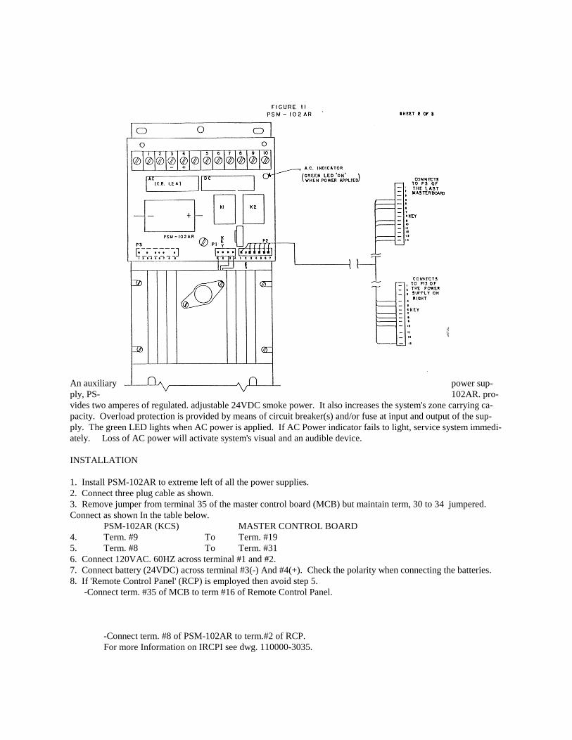
An auxiliary power sup-ply, PS- 102AR. pro-vides two amperes of regulated. adjustable 24VDC smoke power. It also increases the system's zone carrying ca-pacity. Overload protection is provided by means of circuit breaker(s) and/or fuse at input and output of the sup-ply. The green LED lights when AC power is applied. If AC Power indicator fails to light, service system immedi-ately. Loss of AC power will activate system's visual and an audible device.
INSTALLATION
1. Install PSM-102AR to extreme left of all the power supplies.2. Connect three plug cable as shown.3. Remove jumper from terminal 35 of the master control board (MCB) but maintain term, 30 to 34 jumpered.Connect as shown In the table below.
PSM-102AR (KCS) MASTER CONTROL BOARD4. Term. #9 To Term. #195. Term. #8 To Term. #316. Connect 120VAC. 60HZ across terminal #1 and #2.7. Connect battery (24VDC) across terminal #3(-) And #4(+). Check the polarity when connecting the batteries.8. If 'Remote Control Panel' (RCP) is employed then avoid step 5. -Connect term. #35 of MCB to term #16 of Remote Control Panel.
-Connect term. #8 of PSM-102AR to term.#2 of RCP.For more Information on IRCPI see dwg. 110000-3035.

POWER REQUIREMENTS: Input 120VAC. 60HZ. 1.2AMPOutput 24VDC at 2.OAMP. 24
FIGURE 11 PSM- 108OPTIONAL SYSTEM POWER SUPPLY
PSM-108 is in optional system power supply without battery charger. It provides two amps of regulated alarm cur-rent in addition to 3.5 amps of unfiltered bell power. The PSM-108 with an external battery charger shall be usedinstead of
PSM-104 when:* (1) The alarm current load In table 1 exceeds .750 amp and*(2) Ampere-hour calculation In part 3 of table 3 requires greater than 28 ampere-hour battery.

Built-in brownout circuit will engage the secondary source (24v battery) when Insufficient A.C. voltage is detected.Supply outputs: 1) Reguated 24VDC 2 ampere maximum. 2) Two unfiltered. unregulated 24 volt nominal full waverectified d.c. outputs, used to power bell circuits. Total output current is 3.5 amperes.Overload protection: A.C. power : two breakers. each 1.2 amperes. Bell power: two PTC, 3.75 amperes.Battery: 3 amperes.Battery charger (R45-24):1) Float type with current limiting and voltage foldback circuitry. Output is set to 27.6voltsNotes: 1. PSM-108 mounts to right of all optional chassis. 2. A 3 wire cable normally connected to P4 (lower left plug) on last (closest) master board.
3. System without auxiliary power supply: A 7 wire cable connected to P3 (lower left side) on last (closest). System with auxiliary power supply: A 13 wire jumper cable connected to adjacent plug (P138) or optional chassis.4. A 12 wire cable connected to P11 (right side) on master board.5. A 24V stand-by battery connects to terminals 4 (-) and terminal 5 (*)6. Connect 120VAC.60MZ across Term #2 and #3.Connect ground lead to Term #1. Current consumption at rated load is 2.4 amperes.7. Remove Jumper from term #35 of MCB-108.8.. Connect Term #7 and #8 of PSM-108 to Term #35 and #31 of MCB-108 respectively.
FIGURE 12 - AUXILIARY SUPPLIES PSM - 104A/204A
1. On intermediate chassis connect a 13 pin jumper cablefrom 13A to adjacent chassis plug P13B. On left most-chassis. connect a 7 pin cable from P13A to P3 (lower left side)on last (closest) master board.2. Ccnnect a 13 wire jumper cable from P138 to adja-
cent chassis plug P13A.3. Connect the 24VDC (PSM-104A and PSM-204A is unfiltered and unregulated) output as desired. To
power bell module (BCM-2) from these supplies refer to figures 2 and 10. To power the Ring-By-Zone module (RBZ-1) refer to figures 2 and 16. Output information is listed below:PSM-104A.-Single 3.5 Ampere supply -- Positive output: Terminal 6 and Pin 3 and 4 of Plug 4Common Negative Output: Terminal 5 and Pin 1 of Plug P4PSM-204A.-Dual 3.5 Ampere Supply .- Positive output Ckt A: Terminal 10 and Pin 3 of Plug P4Positive output Ckt B: Terminal 6 and Pin 4 of Plug P4 Common (Negative): Terminal 5 and 9 and Pin 1 of Plug P4
4. A 24V standby battery connects to terminal 3 (negative) and terminal 4 (positive). Maximum battery load during power failure is 4 amperes for PSM-104A and 8 amperes for PSM-204A.
5. A.C. Power connects to terminal 1 and 2. Standard A.C. input Is 120V. 60HZ. Current consumption at rated load is 1.2 ampere for PSM-104AB and 2.4 amperes for PSM-204AS.
6. Install protective cover over terminal block before energizing system.7. Denotes components used on PSM-204A only.
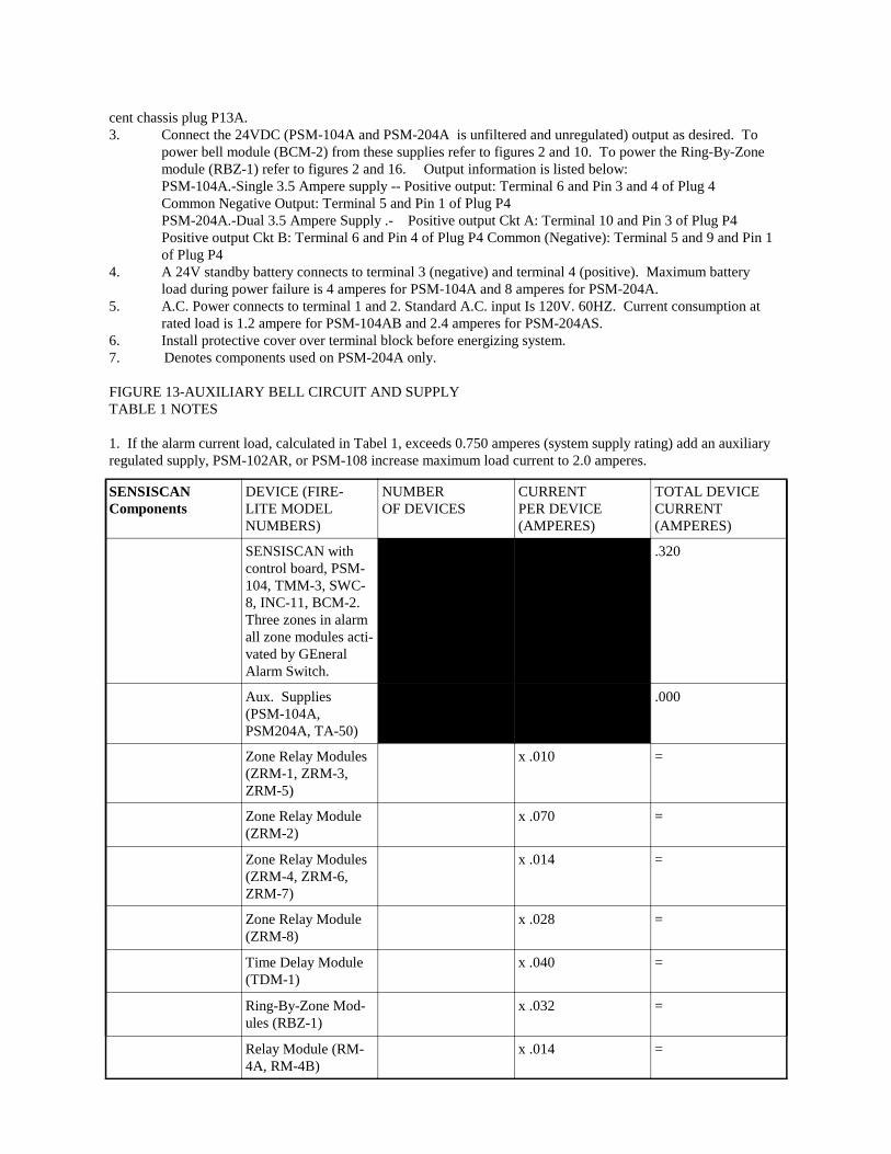
FIGURE 13-AUXILIARY BELL CIRCUIT AND SUPPLYTABLE 1 NOTES
1. If the alarm current load, calculated in Tabel 1, exceeds 0.750 amperes (system supply rating) add an auxiliaryregulated supply, PSM-102AR, or PSM-108 increase maximum load current to 2.0 amperes.
SENSISCANComponents
DEVICE (FIRE-LITE MODELNUMBERS)
NUMBEROF DEVICES
CURRENTPER DEVICE(AMPERES)
TOTAL DEVICECURRENT(AMPERES)
SENSISCAN withcontrol board, PSM-104, TMM-3, SWC-8, INC-11, BCM-2.Three zones in alarmall zone modules acti-vated by GEneralAlarm Switch.
.320
Aux. Supplies(PSM-104A,PSM204A, TA-50)
.000
Zone Relay Modules(ZRM-1, ZRM-3,ZRM-5)
x .010 =
Zone Relay Module(ZRM-2)
x .070 =
Zone Relay Modules(ZRM-4, ZRM-6,ZRM-7)
x .014 =
Zone Relay Module(ZRM-8)
x .028 =
Time Delay Module(TDM-1)
x .040 =
Ring-By-Zone Mod-ules (RBZ-1)
x .032 =
Relay Module (RM-4A, RM-4B)
x .014 =

Bell CKT. and Sup-ply (PSM-104B,PSM 204B, PSM-404B, PSM-408B
x .018 =
Dual Zone Card(ANC-2, WFC-1,WFC-2)
x .012 =
Cross Zone DelayRelease Module(CZM-1)
x .090 =
Cross Zone DelayRelease Module(CZM-3)
x .160 =
Circuit VerificationCArd Module CVC-2
x .015 =
ExternalComponents
Two Wire DetectorHeads-Standby Cur-rent (SD-12, SD-32,CP-700 Series)
x .0001 =
Four Wire DetectorHead (SD14BW,Standby)
x .0001 =
Four Wire DetectorHead (SD34-24VDC, Standby)
x .00015 =
Ebd of Line Relay(SDLR-B, Use withFour Wire Detec-tors)
x .025 =
Above 30 Zones,Add. .050 for everyadditional 10 Zones
x .050 =
=
Alarm Current Load on Regulator (Add Last Column)
FIGURE 13-AUXILIARY BELL CIRCUIT AND SUPPLYPSM-104B, 204B, 404B, 408B

2. Table 1 is based on:a) Ten percent of the total number of zone, but not less than three zones, being in the alarmed state; andb) All zone functions being activated by General Alarm Switchc) Cross Zone Delay Release Modules (CZM-1 & CZM-3) in alarm
TABLE 2 : A.C. CURRENT REQUIREMENTS
POWER SUPPLY TYPE NUMBER USED MAXIMUM INOUTCURRENT (AMPERES)
TOTAL INPUT CUR-RENT (AMPERES)
System Supply (PSM-104) 1.20
Auxiliary Supplies (PSM-104A, PSM-104B, PSM-102AR, PSM-404B, TA-50)
X 1.20 =
Dual Auxiliary Supplies(PSM-204A, PSM-204B,PSM-108, PSM-408B)
X 2.40 =
Total A.C. Current Re-quirements at 120V (AddLast Column)
TABLE 2 NOTES
1. Table 2 is based on full load condition.
TABLE 3: STANDBY BATTERY REQUIREMENTSPART 1: CALCULATION FOR BATTERY STANDBY CURRENT
DEVICE(FIRE-LITEMODEL NUMBERS)
NUMBER OF DEVICES CURRENT PER DEVICE(AMPERES)
TOTAL DEVICE CUR-RENT (AMPERES)
SENSISCAN with controlboard PSM-104, TMM-3,SWC-8, INC-11, BCM-2Note: AC power off, visual& audible trouble signal
.055
Zone Relay Modules(ZRM Series)
.000
Unreg. Aux. Supplies(PSM-104A, PSM-204A)
.000

Regulated Aux. Supply(PSM-102AR, PSM-108)
x .005 =
Bell Ckt. and Supply(PSM-104B, PSM-204B,PSM-404B, PSM-408)
x .005 =
Master Zone Boards(MZB Series)
x .002 =
Dual Zone Cards(ANC-2, WFC-1, WFC-2)
x .012 =
Ring-By-Zone(RBZ-1)
x .003 =
Time Delay Module(TDM-1)
x .006 =
Cross Zone Delay ReleaseModules (CZM-1, CZM-3)
x .025 =
Tone Amplifier (TA-50) x .30 =
Two Wire Detector Heads(SD-12, SD-32, CP-700Series)
x .0001 =
Four Wire Detector Head(SD14BW)
x .00015 =
Four Wire Detector Head(SD34-24VDC)
x .005 =
Zone Coder Model ZC-83 x .055 =
Circuit Verification CardModel CVC-2
x .015 =
End of Line Relay (SDLR-B, not required for 2 wiredetectors)
x .025 =
Remote Indicator (RZISeries-for Sonalert)
x .012 =
Remote Station Loading(Enter only if troubletransmission inhibited)
=
Remote Trouble SignalingDevices-Bells, Etc.
=
Other Devices using SEN-SISCAN Power
=
=
Battery Standby Current(Add Last Column)
=

PART 2: CALCULATION FOR ALARM LOADING ON BATTERY
POWER SUPPLY TYPE NUMBER USED MAXIMUM ALARMCURRENT (AMPERES)
TOTAL TYPE CUR-RENT (AMPERES)
System Supply (PSM-104) 4
Auxiliary Supplies (PSM-104A, PSM-104B, PSM-404)
x 4
Tone Amplifier (TA-50) x 4
Dual Auxiliary Supplies(PSM-204A, PSM-204B,PSM-408)
x 8
Auxiliary Regulated Sup-ply (PSM-102AR)
x 2.5
Battery Alarm Load (AddLast Column)
PART 3: CALCULATE AMPERE-HOURS
1. Battery standby current frompart 1
2. Standby time in hours (generally24 or 60 hrs.)*
3. Standby ampere-hours, mulitplyline 1 by line 2
4. Battery alarm load in amperes
5. Alarm time in hours
6. Alarm ampere-hours, mulitiplyline4 by line 5
7. Total ampere-hours, add line 3and 6
8. Select battery from part 4 with ampere-hour rating larger than line 7. Indicate battery selected on markinglabel attached to control unit door.

PART 4: BATTERY SELECTION
AMPERE-HOUR RATING BATTERY(FIRE-LITE PART NUMBER)
CABINET SIZE(S)
9 Four (4) Globe-Union (GC-690) ALL
18 Two (2) Eagle Picher (GC-1218) ALL
23 Two (2) Globe-Union (GC-1220) ALL
28 Two (2) Globe-Union (GC-128) C.D. (with ALL Supplies on backplate)
*NFPA 72A and 72D required 24 hours standby. NFPA 72B and 72C requires 60 hours standby.

NOTES:
1. For non-disconnectable bell remove jumper J3 but leave J2.2. For disconnectable bell remove jumper J2 but leave J3.3. To convert from a steady bell signal to a March Time (MTC) bell signal, remove jumper J1. March TimeRate is adjusted using “MTC” potentiometer.4. On intermediate chassis connect a 13 pin jumper cable from 13A to adjacent chassis plug P13B. On left mostchassis, connect a 7 pin cable from P13A to P3 (lower left side) on last (closest) master board.5. Connect a 13 wire jumper cable from P13B to adjacent chassis plug P13A.6. Connect signalling circuits as shown. Use polarized, U.L. listed, signalling device with a minimum rated volt-age range of 18 to 30VDC. Size wire for a maximum drop of 2VDC. Compatible FIRE-LITE model includeBDP-24 Bell, HDP-24 Horn, and STH-72-24D Strobe Horn.
Maximum Load Per Circuit # of Circuits
PS-4048 .85 ampere 4
PSM-104B 1.75 ampere 2
PSM-408B 1.75 ampere 4
PSM-204B 3.5 ampere 2
7. A 24V standby battery connects to terminal 3 (negative) and terminal 4 (positive). Maximum battery loadduring power failure is 3.5 amp for PSM-104AB, PSM-404B and 7 amperes for PSM-204AB, PSM-408B.8. A.C. power connects to terminals 1 and 2. Standard A.C. input is 120VAC, 60HZ. Current consumption atrated load is 1.2 amperes. for PSM-104AB, PSM-404B, and 2.4 amps for PSM-204AB, PSM-408B.9. Install protective cover over terminal block before energizing system.10.- - -Denotes components used on PSM-204B and PSM-408B only.11. Both circuits are power limited.
