plug-in (11 pin) monitoring devices - l&o sales · a second pulse will de-energise the relay...
TRANSCRIPT

142 • MCE
10V, 30V AC/DC10V, 230V, 400V Ac
PLUG-IN (11 PIN)MONITORING DEVICES
MODEl FFr FFrP-1 & FFrP-2 FFrM tPr
PrODUct Mains ControlledFlip-Flop Relay
Flip-Flop RelayPulse Controlled Single Pole
& Double Pole
Flip-Flop Relaywith Memory
Thermistor Protection Relay
DEScriPtiON OF OPErAtiON
Used for alternating two pumps for duty and stand-by operation. Applying power for 30 seconds or longer and then removing the power will cause the relay to alter its state. The relay will remain in this new state until the power is re-applied and once again removed when it will then return to the initial position.
With power on terminals 2 + 10 and pulse on terminals 5 + 7 , the relay energises.
A second pulse will de-energise the relay and it returns to its normal state. On loss of power on terminals 2 + 10; the relay, if energised, will de-energise and return to its original OFF state (NO MEMORY).
With power on terminals 2 + 10 a closure or pulse across terminals 5 + 7 will cause the relay to energise.
A second pulse on terminals 5 + 7 will reset the relay to its normal state.
After loss and re-power on terminals 2 + 10, the status of the relay, at that time, will not alter.
Only after another closure or pulse on terminals 5 + 7 will the relay once again alter its state (MEMORY).
Interfacing with PTC sensors as per DIN44081 (Thermistors) embedded in the motor windings, the TPR offers excellent motor protection. The LED’s indicate trip conditions for motor overheat, cable fault (short or open circuit) as well as the relays latch condition. Latching is enabled by bridging terminals 8 + 9.Open circuit voltage <=2,5V. Short circuit current= 1ma (Max). Maximum cold resistance of 1 to 6 sensors connected - 1500ΏTriggering threshold3100Ώ ± 10%Recovery threshold1650Ώ ± 10%
cONtrOlS AND lABEl DAtA
WiriNGDiAGrAM
VOltAGE 110V, 230V, 400V AC
liSt PricE r569.00 r391.00 r426.00 r370.00

MCE • 143
PLUG-IN (11 PIN)MONITORING DEVICES
MODEl llc llc3 AEl
PrODUct Liquid Level Control“Filling & Emptying”DIP Switch Selectable
3 Level liquid Level Control“Filling & Emptying” with duty cycling
DIP Switch Selectable
Aquaman Electrode
DEScriPtiON OF OPErAtiON
Used in conjunction with 3 conductive probes connected to terminals 5 (high), 6 (middle/low) and 7 (bottom/common).Filling: When liquid drops below the middle probe, the relay energises. The relay remains energised until the level reaches the high level probe and then de-energises.Emptying: When the liquid rises above the high probe, the relay energises. The relay de-energises when the liquid falls below the middle probe.Sensitivity - 50ΏUse “AEL” Aquaman hanging probes.
Used for control of water levels in tanks and sumps over short distances. The LLC3 controls 2 pump relays operated at different levels for “Duty” and “Standby” operation. The unit automatically alternates the pump relays between duty and standby using a built-in flip-flop action.There are 4 DIP switches available to select emptying or fillingFilling: Sw 1 + 2 - ON (up position); Sw 3 + 4 - OFF (down position)Emptying: Sw 1 + 2 - OFF(down position); Sw 3 + 4 - ON (up position)Avanti AEL probes: connected to the terminals:5 - “High;” 6 - “Middle;” 7 - “Low;” 8 - “Common”Filling: If the level is below probe 7 - “Low” both relays will energise and when the level reaches probe 5 - “High” both relays will de-energise. When the level drops below probe 6 - “Middle” relay 1 will energise and de-energise when the level reaches probe 5 - “High.” The next on cycle with probe 6 - “Middle” out of the water, relay 2 will energise (alternating). If the level continues to fall and goes below the probe 7 - “Low,” both pumps will energise and only de-energise when probe 5 - “High” is reached (all probes in the water).Emptying: When a rising level reaches probe 6 - “Middle,” relay 2 energises and de-energises when probe 7 - “Low” is reached. On the next rising level to probe 6 - “Middle” - relay 1 will energise (alternating). If the level continues to rise and probe 5 - “High” is reached, both relays will be energised (Duty & Standby) and when the level reaches probe 7 - “Low” both relays will de-energise.
Installation Instructions:1) Strip PVC wire 25mm long2) Feed cover/cap onto wire. Large threaded opening facing stripped end.3) Connect copper wire through stud hole, between nut and washer. Do not wind around stud and ensure copper wire tip does not extend past edge of the washer.4) Cover connection and exposed copper with compound. Ensure compound extends in the conical shape 25mm up the wire.5) Screw on cap. Use extruded excess compound to seal wire inlet (Sealing compound supplied with probe).
cONtrOlS AND lABEl DAtA
WiriNG DiAGrAM
VOltAGE 230V, 400V AC 230V, 400V AC
liSt PricE r328.00 r489.00 r76.00
144 • MCE
PLUG-IN (11 PIN)MONITORING DEVICES
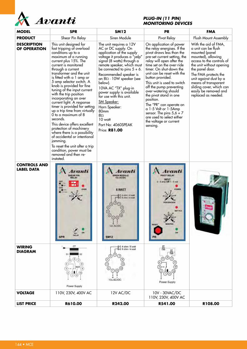
MODEl SPr SM12 Pr FMA
PrODUct Shear Pin Relay Siren Module Pivot Relay Flush Mount Assembly
DEScriPtiON OF OPErAtiON
This unit designed for fast tripping of overload conditions up to a maximum of a running current plus 15%. The current is monitored through a current transformer and the unit is fitted with a 1 amp or 5 amp selector switch. A knob is provided for fine tuning of the input current with the trip position incorporating an over current light. A response timer is provided for setting up a trip time from virtually 0 to a maximum of 8 seconds.This device offers excellent protection of machinery where there is a possibility of accidental or intentional jamming.To reset the unit after a trip condition, power must be removed and then re-instated.
The unit requires a 12V AC or DC supply. On application of the supply voltage it produces a “yelp” signal (8 watts) through a remote speaker, which must be connected to pins 5 + 6.Recommended speaker is an 8Ώ - 10W speaker (see below).10VA AC “TX” plug-in power supply is available for use with this unit.SM Speaker:Horn Speaker:80mm8Ώ10 wattPart No: 4060SPEAKPrice: r81.00
On application of power the relay energises. If the pivot draws less than the pre-set current setting, the relay will open after the time set on the over-ride timer. On shut-down the unit can be reset with the button provided.This unit is used to switch off the pump preventing over-watering should the pivot stand in one position.The “PR” can operate on a 1-5 Volt or 1-5Amp sensor. The pins 5,6 + 7 are used to select either the voltage or current sensing.
With the aid of FMA, a unit can be flush mounted (panel mounted), allowing access to the controls of the unit without opening the panel door.The FMA protects the unit against dust by a means of transparent sliding cover, which can easily be removed and replaced as needed.
cONtrOlS AND lABEl DAtA
WiriNG DiAGrAM
VOltAGE 110V, 230V, 400V AC 12V AC/DC 10V - 30VAC/DC110V, 230V, 400V AC
liSt PricE r610.00 r242.00 r541.00 r108.00
MCE • 145
SPECIFICATION/DATA SHEET
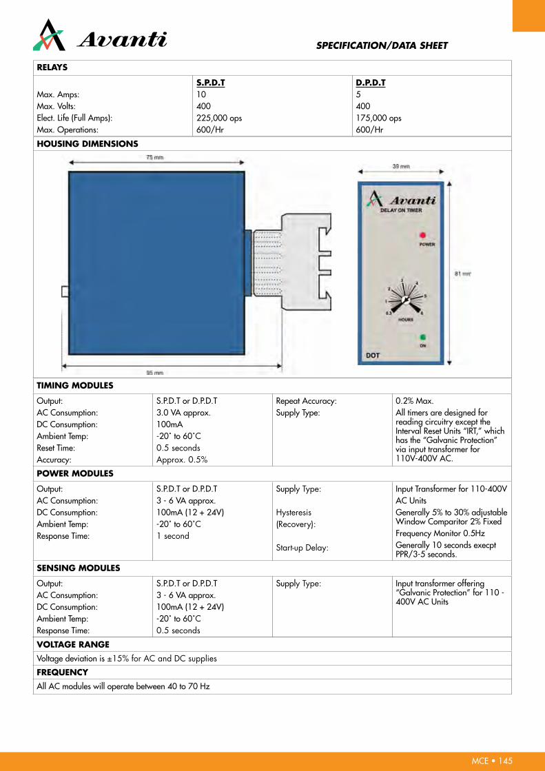
rElAYS
Max. Amps:Max. Volts:Elect. Life (Full Amps):Max. Operations:
S.P.D.t10400225,000 ops600/Hr
D.P.D.t5400175,000 ops600/Hr
HOUSiNG DiMENSiONS
tiMiNG MODUlES
Output:AC Consumption:DC Consumption:Ambient Temp:Reset Time:Accuracy:
S.P.D.T or D.P.D.T3.0 VA approx.100mA-20˚ to 60˚C0.5 secondsApprox. 0.5%
Repeat Accuracy:Supply Type:
0.2% Max.All timers are designed for reading circuitry except the Interval Reset Units “IRT,” which has the “Galvanic Protection” via input transformer for 110V-400V AC.
POWEr MODUlES
Output:AC Consumption:DC Consumption:Ambient Temp:Response Time:
S.P.D.T or D.P.D.T3 - 6 VA approx.100mA (12 + 24V)-20˚ to 60˚C1 second
Supply Type:
Hysteresis(Recovery):
Start-up Delay:
Input Transformer for 110-400VAC UnitsGenerally 5% to 30% adjustable Window Comparitor 2% FixedFrequency Monitor 0.5HzGenerally 10 seconds execpt PPR/3-5 seconds.
SENSiNG MODUlES
Output:AC Consumption:DC Consumption:Ambient Temp:Response Time:
S.P.D.T or D.P.D.T3 - 6 VA approx.100mA (12 + 24V)-20˚ to 60˚C0.5 seconds
Supply Type: Input transformer offering “Galvanic Protection” for 110 - 400V AC Units
VOltAGE rANGE
Voltage deviation is ±15% for AC and DC supplies
FrEQUENcY
All AC modules will operate between 40 to 70 Hz

146 • MCE
TYPICAL WIRING DIAGRAMS FOR PUMP PROTECTION RELAY
PPr-3t8 withStop-StartButtons
PPr-3t8Auto-Startwith ON/OFFswitch
PPr-1t8with Stop-Startbuttons230V

Bulkhead Fitting Diagrams
Square Bulkhead
Round Eyelid Bulkhead
Square Eyelid Bulkhead
Oval vertical & Oval Vertical Eyelid Bulkhead
Round Bulkhead
Oval Horizontal & Oval Horizontal Eyelid Bulkhead
5W Dimmable Bulbs
8W Dimmable Bulbs
4,5W Spotlights 60° Beam Angle
10W Dimmable Bulbs
ø62 mm
122 mm
(E27)
ø62 mm
122 mm
(B22)
(E27)
ø54 mm
103 mm
(B22)(E14)
ø54 mm
104 mm
ø54 mm
113 mm
ø120 mm
142 mm
(E27)
ø50 mm
69 mm
(E27)
(E14)
ø50 mm
62 mm
(B22)
ø50 mm
54 mm
ø50 mm
52 mm
ø50 mm
73 mm
ø39.5 mm
151 mm
ø50 mm
61 mm
ø50 mm
58.5mm
(E26)
ø50 mm
75 mm
(E14)
ø50 mm
79 mm(B22)
ø50 mm
68.5 mm
(E14)
ø35 mm
105 mm
1.5M (1,514mm) / 1.2M(1,213mm) 0.9M (894mm) / 0.6M (589mm)
1.5M (1,500mm) / 1.2M(1,199mm) 0.9M (908mm) / 0.6M (604mm)
ø26mm
42mm
1.5M (1,518mm) / 1.2M(1,218mm) 0.9M (918mm) / 0.6M (608mm)
ø100 mm
110 mm
ø95 mm
120 mm
(E27)
LINE ART
10W BULB
5W-MINI BULB
PAR38/30
PAR16
SPOTLGIHT
T8
DOWNLIGHT
CANDLE BULB PLC
ø62 mm
122 mm
(E27)
ø62 mm
122 mm
(B22)
(E27)
ø54 mm
103 mm
(B22)(E14)
ø54 mm
104 mm
ø54 mm
113 mm
ø120 mm
142 mm
(E27)
ø50 mm
69 mm
(E27)
(E14)
ø50 mm
62 mm
(B22)
ø50 mm
54 mm
ø50 mm
52 mm
ø50 mm
73 mm
ø39.5 mm
151 mm
ø50 mm
61 mm
ø50 mm
58.5mm
(E26)
ø50 mm
75 mm
(E14)
ø50 mm
79 mm(B22)
ø50 mm
68.5 mm
(E14)
ø35 mm
105 mm
1.5M (1,514mm) / 1.2M(1,213mm) 0.9M (894mm) / 0.6M (589mm)
1.5M (1,500mm) / 1.2M(1,199mm) 0.9M (908mm) / 0.6M (604mm)
ø26mm
42mm
1.5M (1,518mm) / 1.2M(1,218mm) 0.9M (918mm) / 0.6M (608mm)
ø100 mm
110 mm
ø95 mm
120 mm
(E27)
LINE ART
10W BULB
5W-MINI BULB
PAR38/30
PAR16
SPOTLGIHT
T8
DOWNLIGHT
CANDLE BULB PLC
(E27)
ø65 mm
112 mm
(E14)
ø65 mm
121 mm
(B22)
ø65 mm
112 mm
8W BULB LINE ART
GU10 MR16
147 • MCE
148 • MCE
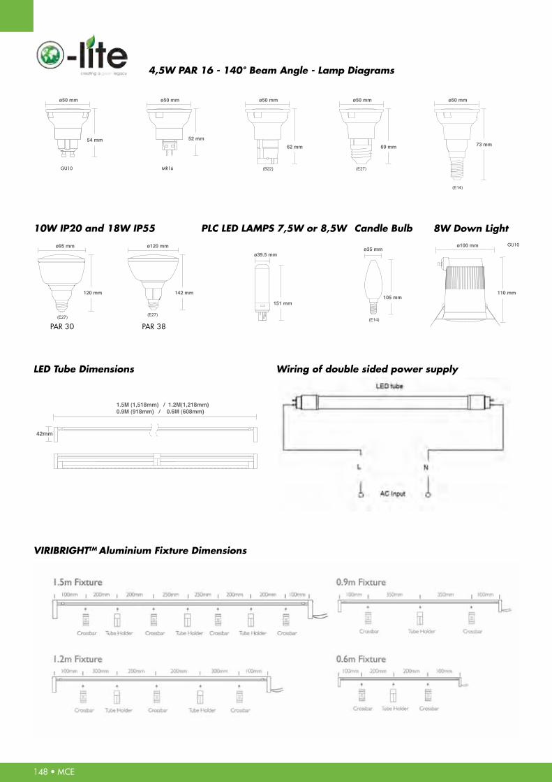
4,5W PAR 16 - 140° Beam Angle - Lamp Diagrams
10W IP20 and 18W IP55
LED Tube Dimensions
VIRIBRIGHTTM Aluminium Fixture Dimensions
Wiring of double sided power supply
PLC LED LAMPS 7,5W or 8,5W Candle Bulb 8W Down Light
ø62 mm
122 mm
(E27)
ø62 mm
122 mm
(B22)
(E27)
ø54 mm
103 mm
(B22)(E14)
ø54 mm
104 mm
ø54 mm
113 mm
ø120 mm
142 mm
(E27)
ø50 mm
69 mm
(E27)
(E14)
ø50 mm
62 mm
(B22)
ø50 mm
54 mm
ø50 mm
52 mm
ø50 mm
73 mm
ø39.5 mm
151 mm
ø50 mm
61 mm
ø50 mm
58.5mm
(E26)
ø50 mm
75 mm
(E14)
ø50 mm
79 mm(B22)
ø50 mm
68.5 mm
(E14)
ø35 mm
105 mm
1.5M (1,514mm) / 1.2M(1,213mm) 0.9M (894mm) / 0.6M (589mm)
1.5M (1,500mm) / 1.2M(1,199mm) 0.9M (908mm) / 0.6M (604mm)
ø26mm
42mm
1.5M (1,518mm) / 1.2M(1,218mm) 0.9M (918mm) / 0.6M (608mm)
ø100 mm
110 mm
ø95 mm
120 mm
(E27)
LINE ART
10W BULB
5W-MINI BULB
PAR38/30
PAR16
SPOTLGIHT
T8
DOWNLIGHT
CANDLE BULB PLC
ø62 mm
122 mm
(E27)
ø62 mm
122 mm
(B22)
(E27)
ø54 mm
103 mm
(B22)(E14)
ø54 mm
104 mm
ø54 mm
113 mm
ø120 mm
142 mm
(E27)
ø50 mm
69 mm
(E27)
(E14)
ø50 mm
62 mm
(B22)
ø50 mm
54 mm
ø50 mm
52 mm
ø50 mm
73 mm
ø39.5 mm
151 mm
ø50 mm
61 mm
ø50 mm
58.5mm
(E26)
ø50 mm
75 mm
(E14)
ø50 mm
79 mm(B22)
ø50 mm
68.5 mm
(E14)
ø35 mm
105 mm
1.5M (1,514mm) / 1.2M(1,213mm) 0.9M (894mm) / 0.6M (589mm)
1.5M (1,500mm) / 1.2M(1,199mm) 0.9M (908mm) / 0.6M (604mm)
ø26mm
42mm
1.5M (1,518mm) / 1.2M(1,218mm) 0.9M (918mm) / 0.6M (608mm)
ø100 mm
110 mm
ø95 mm
120 mm
(E27)
LINE ART
10W BULB
5W-MINI BULB
PAR38/30
PAR16
SPOTLGIHT
T8
DOWNLIGHT
CANDLE BULB PLC
GU10
GU10
PAR 30 PAR 38
MR16
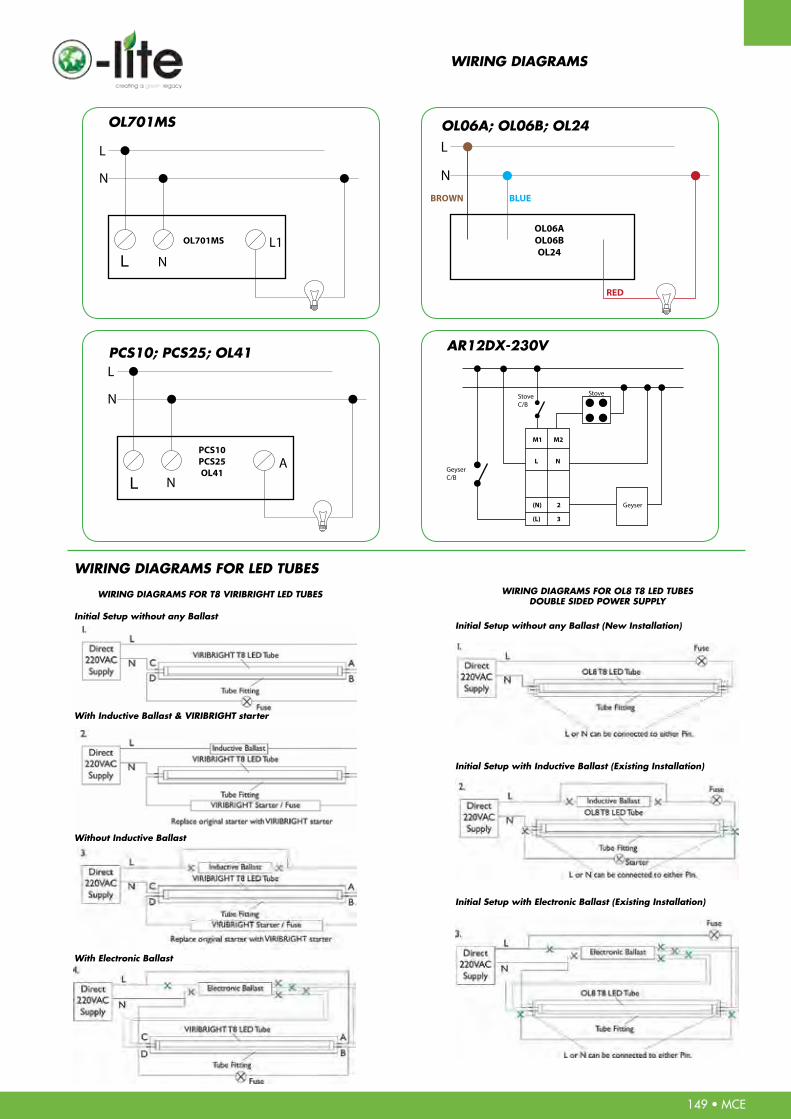
WIRING DIAGRAMS
WIRING DIAGRAMS FOR T8 VIRIBRIGHT LED TUBES WIRING DIAGRAMS FOR OL8 T8 LED TUBESDOUBLE SIDED POWER SUPPLY
Initial Setup without any BallastInitial Setup without any Ballast (New Installation)
Initial Setup with Inductive Ballast (Existing Installation)
Initial Setup with Electronic Ballast (Existing Installation)
With Inductive Ballast & VIRIBRIGHT starter
Without Inductive Ballast
With Electronic Ballast
WIRING DIAGRAMS FOR LED TUBES
OL701MS
NL1OL701MS
L
N
PCS10; PCS25; OL41
NA
PCS10PCS25OL41
L
N
OL06A; OL06B; OL24
OL06AOL06BOL24
L
NBROWN BLUE
RED
AR12DX-230V
L
L
149 • MCE

150 • MCE
• U-SERIESMOULDED CASE CIRCUIT BREAKER CASCADING TABLE - 415VACElEctric
UAB-c
UAB100C UCB250R UCB400R UCB630R UCB800R UAB100S UCB250S UCB400S UCB630S UCB800S
5-100 125-250 250-400 500, 630 700, 800 15-100 125-250 250-400 500, 630 700, 800
KC3 1-63 3 6 7,5 10 10 10
KC6-T 1-63 6 7,5 7,5 10 10 10
KC10-T 1-125 10 14 14 14 14 18 18 20 20
UAB100R 15-100 25 30 35 35 35 42 42
UCB50R 15-50 25 30 35 35 30 35 42 42
UCB100R 15-100 25 30 35 35 35 42 42
UCB250R 125-250 18 30 35 35 30 35 35
UCB400R 250-400 30 35 50
UAB50S 15-50 25 30 35 35 30 35 42 42
UAB100S 15-100 30 35 35 35 42 42
UCB100S 15-100 36 45 45 42 50 50
UCB250S 125-250 25 30 35 35 35 42 42
UCB400S 250-400 42 45 65
UAB50H 15-50 30 35 35 42 42 42
UCB50H 15-50 42 45 45 50 50
UCB100H 15-125 42 45 45 50 50
UCB250H 125-250 42 45 45 50 50
UCB400H 250-400 65
UCB50L 15-50 50 65 65
UCB100L 15-125 50 65 65
UCB250L 125-250 50 65 65
UCB400L 250-400 100
UPB100H 15-125 100
UPB250H 100-250 100
UPB100L 15-125 130
UPB250L 100-250 130
UAB-r UAB/UcB-SRecognitionCategory
KC
UAB/UCB-R
UAB/UCB-S
UAB/UCB-H
UCB-L
UPB-H
UPB-L
ModelRated
Current (A) Breaking
Capacity[Icu]
(kA r.m.s)10 18 30 45 45 30 25 42 65 65
UPSTREAM
DO
WN
STREA
M

151 • MCE
• U-SERIESMOULDED CASE CIRCUIT BREAKER CASCADING TABLE - 415VACElEctric
UCB100H UCB250H UCB400H UCB630H UCB800H UCB100L UCB250L UCB400L UCB630L UCB800L UPB100H UPB250H UPB100L UPB250L
15-125 125-150 250-400 500, 630 700, 800 15-125 125-250 250-400 500, 630 700, 800 15-125 100-250 15-125 100-250
14 14 18 18 18 20
14 14 18 20 20 20
18 18 20 20 20 20 20 25 25 25 25 25 35 35
35 42 50 50 35 50 50 50 50 50
35 35 42 50 50 42 42 50 50 50 50 50 50 50
35 42 50 50 42 50 50 50 50 50
35 42 42 42 42 42
50 50
35 35 42 50 50 42 42 50 50 50 50 50 50 50
42 45 50 50 50 65 65 65 50 65
42 50 65 65 50 75 75 75 65 65
42 50 50 50 50 50
75 85
42 42 45 50 50 50 50 65 65 65 50 50 65 65
60 75 75 50 50 85 85 85 85 85 85 85
60 75 75 50 85 85 85 85 85
60 75 75 85 85 85
85 100
65 85 85 100 100 100 100 100 100 100
65 85 85 100 100 100 100 100
65 85 85 100 100 100
130 130
130
UcB-l UPB-H UPB-lUcB-H
8585654242 50 50 100 100 100 100 100 130 130
152 • MCE
SPECIFICATION SHEETSDATA SHEETS
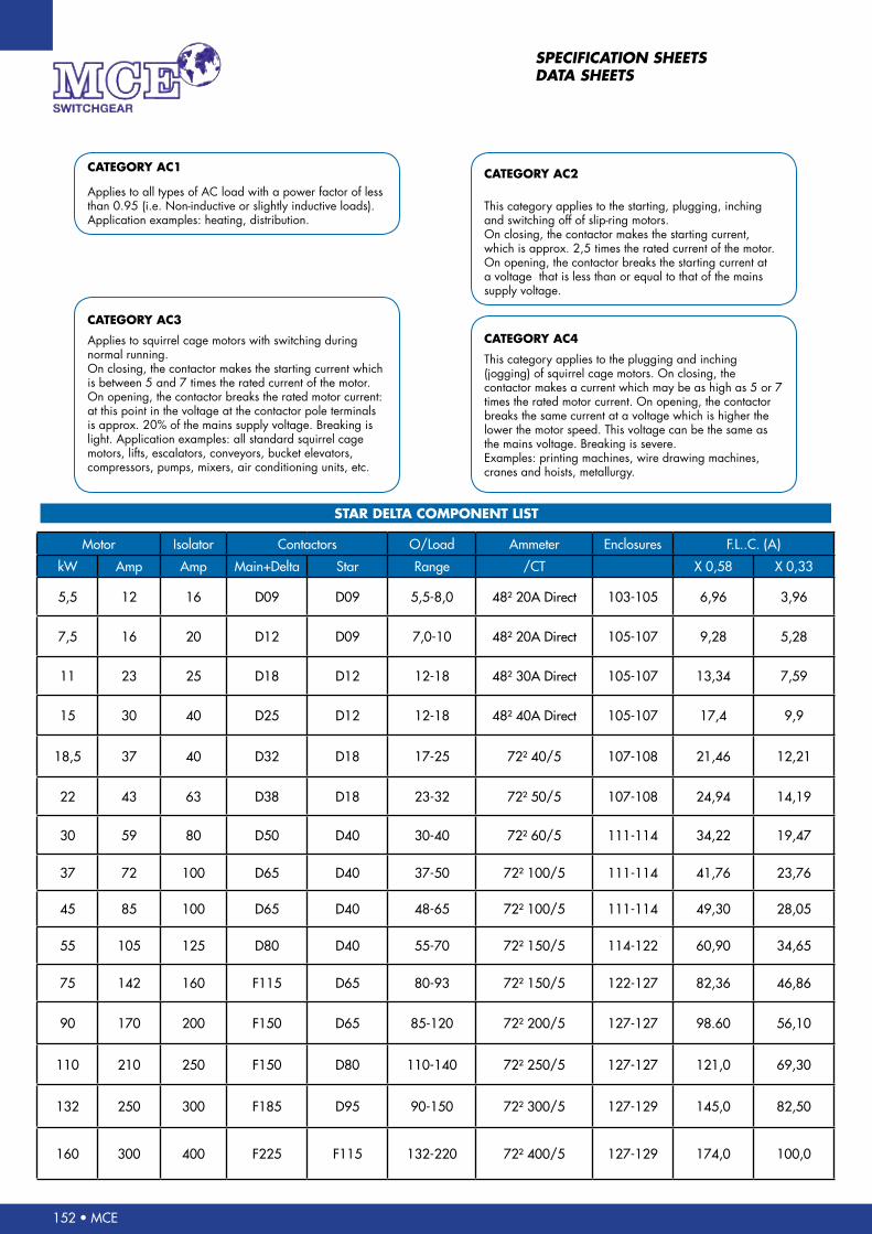
Applies to all types of AC load with a power factor of less than 0.95 (i.e. Non-inductive or slightly inductive loads). Application examples: heating, distribution.
cAtEGOrY Ac1
cAtEGOrY Ac3
Applies to squirrel cage motors with switching during normal running.On closing, the contactor makes the starting current which is between 5 and 7 times the rated current of the motor. On opening, the contactor breaks the rated motor current: at this point in the voltage at the contactor pole terminals is approx. 20% of the mains supply voltage. Breaking is light. Application examples: all standard squirrel cage motors, lifts, escalators, conveyors, bucket elevators, compressors, pumps, mixers, air conditioning units, etc.
cAtEGOrY Ac4
This category applies to the plugging and inching (jogging) of squirrel cage motors. On closing, the contactor makes a current which may be as high as 5 or 7 times the rated motor current. On opening, the contactor breaks the same current at a voltage which is higher the lower the motor speed. This voltage can be the same as the mains voltage. Breaking is severe.Examples: printing machines, wire drawing machines, cranes and hoists, metallurgy.
cAtEGOrY Ac2
This category applies to the starting, plugging, inching and switching off of slip-ring motors.On closing, the contactor makes the starting current, which is approx. 2,5 times the rated current of the motor.On opening, the contactor breaks the starting current at a voltage that is less than or equal to that of the mains supply voltage.
StAr DEltA cOMPONENt liSt
Motor Isolator Contactors O/Load Ammeter Enclosures F.L..C. (A)
kW Amp Amp Main+Delta Star Range /CT X 0,58 X 0,33
5,5 12 16 D09 D09 5,5-8,0 48² 20A Direct 103-105 6,96 3,96
7,5 16 20 D12 D09 7,0-10 48² 20A Direct 105-107 9,28 5,28
11 23 25 D18 D12 12-18 48² 30A Direct 105-107 13,34 7,59
15 30 40 D25 D12 12-18 48² 40A Direct 105-107 17,4 9,9
18,5 37 40 D32 D18 17-25 72² 40/5 107-108 21,46 12,21
22 43 63 D38 D18 23-32 72² 50/5 107-108 24,94 14,19
30 59 80 D50 D40 30-40 72² 60/5 111-114 34,22 19,47
37 72 100 D65 D40 37-50 72² 100/5 111-114 41,76 23,76
45 85 100 D65 D40 48-65 72² 100/5 111-114 49,30 28,05
55 105 125 D80 D40 55-70 72² 150/5 114-122 60,90 34,65
75 142 160 F115 D65 80-93 72² 150/5 122-127 82,36 46,86
90 170 200 F150 D65 85-120 72² 200/5 127-127 98.60 56,10
110 210 250 F150 D80 110-140 72² 250/5 127-127 121,0 69,30
132 250 300 F185 D95 90-150 72² 300/5 127-129 145,0 82,50
160 300 400 F225 F115 132-220 72² 400/5 127-129 174,0 100,0

MCE • 153
The value as indicated below are for 3 Phase, 4 Pole Motors 50/60Hz in general use. The Motor power rating of MCE Contactors, Starters and Overloads are based on the values of this table.
StAr DEltA rAtiNGS ArE cAlcUlAtED At FUll lOAD cUrrENt X 0,58These values are given as a guide only. They may vary depending on the type of motor
and manufacturer.
RATED MOTOR CURRENT CONVERSION TABLE
rAtED
kW
rAtED
HP
AMPS
230V
AMPS
400V
AMPS
440V
AMPS
500V
0,37 1/2 2,9 0,98 0,9 0,79 - - -
0,55 3/4 4,6 1,5 1,4 1,2 - - -
0,75 1 5,7 1,9 1,7 1,5 - - -
1,1 1,5 7,3 2,4 2,4 2,1 - - -
1,5 2 9,9 3,3 3,1 2,7 - - -
2,2 3 14,4 4,7 4,4 4,8 - - -
3 4 19,1 6,2 5,8 5,1 - - -
3,7 5 23,4 7,3 7,1 6,2 - - -
4 5,5 24 8,1 7,3 6,4 4,6 4,3 3,78
5,5 7,5 33 10,9 10,4 9,1 6,4 6,1 5,37
7,5 10 44,7 14,7 13,4 11,7 6,8 7,8 6,8
9 12 53,5 17,5 16,9 14,8 10,2 9,8 8,6
10 13,5 57,3 19 17,3 15,2 10,9 10 8,8
11 15 65 20,9 20,1 17,7 12,2 11,7 10,3
15 20 86,1 28,5 26,5 23,3 16,5 15,4 13,5
18,5 25 106,1 35,5 32,8 28,8 20,4 19 16,7
22 30 124,3 41,8 39 34,3 24,2 22,6 19,8
25 35 141,5 49,4 45,3 39,8 28,5 26,2 23
30 40 170,3 57 55 48,4 33 31,9 28
37 50 208,5 68,4 64 56,3 39,5 37 32,5
45 60 242,9 80,7 76 66,8 46,6 43,9 38,6
55 75 301,3 99,7 90 79,2 57,6 52 45,7
75 100 396 131,1 125 110 76 72,2 63,5
90 125 - 161,5 146 128,4 93 84 73,9
110 150 - 194,7 178 156,6 112,1 102 89,7
132 180 - 232,7 215 189,2 134,4 124 109,1
160 220 - 285 256 225,2 164,5 147,8 130
185 250 - 324,9 295 259,6 187,6 170,3 149,8
200 270 - 351,5 321 282,4 203 185 162,8
400V 440VStAr DEltA
500V

154 • MCE
VOLTAGE DROP MEASUREMENT CALCULATION
2 cOrE cABlE
3/4 cOrE cABlE
SiZE
Metricmm
Amp Volt DropMV/A/M
Amp Volt DropMV/A/M
Amp Volt DropMV/A/M
Amp Volt DropMV/A/M
1 mm 13 40 16 40 19 40 13 40
1.5 mm 17 27 20 27 25 27 17 27
2.5 mm 23 16 28 16 34 16 23 16
4 mm 31 10 38 10 45 10 31 10
6 mm 40 6.9 48 6.9 58 6.9 40 6.9
10 mm 55 4.3 66 4.3 78 4.3 55 4.3
16 mm 72 2.6 88 2.6 105 2.6 72 2.6
25 mm 96 1.7 115 1.7 140 1.7 96 1.7
35 mm 120 1.3 140 1.2 170 1.2 120 1.3
50 mm 150 0.88 175 0.88 210 0.83 150 0.93
70 mm 180 0.65 220 0.65 235 0.59 180 0.71
95 mm 220 0.48 265 0.48 285 0.44 220 0.56
120 mm 255 0.40 305 0.40 330 0.35 255 0.48
150 mm 290 0.33 350 0.33 380 0.28 290 0.42
185 mm 335 0.29 400 0.29 430 0.24 335 0.39
240 mm 390 0.25 465 0.25 465 0.19 390 0.35
300 mm 450 0.23 540 0.23 540 0.16 450 0.33
SiZE
Metricmm
Amp Volt DropMV/A/M
Amp Volt DropMV/A/M
Amp Volt DropMV/A/M
Amp Volt DropMV/A/M
1 mm 11 35 13 35 17 35 12 35
1.5 mm 14 23 17 23 22 23 16 23
2.5 mm 19 14 23 14 31 14 21 14
4 mm 26 9 31 9 41 9 28 9
6 mm 33 6 40 6 52 6 36 6
10 mm 46 3.5 55 3.5 66 3.5 50 3.5
16 mm 61 2.2 72 2.2 88 2.2 66 2.2
25 mm 81 1.4 96 1.4 115 1.4 87 1.4
35 mm 99 1 120 1 140 1 110 1.1
50 mm 125 0.15 150 0.15 160 0.70 135 0.78
70 mm 155 0.52 180 0.52 200 0.47 165 0.59
95 mm 185 0.40 220 0.40 240 0.34 200 0.47
120 mm 215 0.34 255 0.34 280 0.28 230 0.40
150 mm 250 0.28 290 0.28 320 0.23 265 0.34
185 mm 280 0.25 335 0.25 365 0.19 300 0.30
240 mm 330 0.22 390 0.22 425 0.16 355 0.27
300 mm 380 0.19 450 0.19 450 0.13 410 0.25
Air
Air
DUct
DUct
GrOUND
GrOUND
WirE iN cONDUit
WirE iN cONDUit
Example:Formula required to calculate volt drop in a cable.Cable size: 25mm x 4 core in groundLength of Cable: 80 MetersFull load of Cable: 100 Amps
(MilliVolt/Amps/Meter) x (Actual Amps used) x (L)ength in meters1000
Calculation = 1.4 x 100 x 80 1000 = 11. 2 Voltage Drop
MCE • 155
OPERATING INSTRUCTIONS
DTS-16C20A DIGITAL PROGRAMMABLE
TIME SWITCHCAUTION! SAFETY PRECAUTIONS:
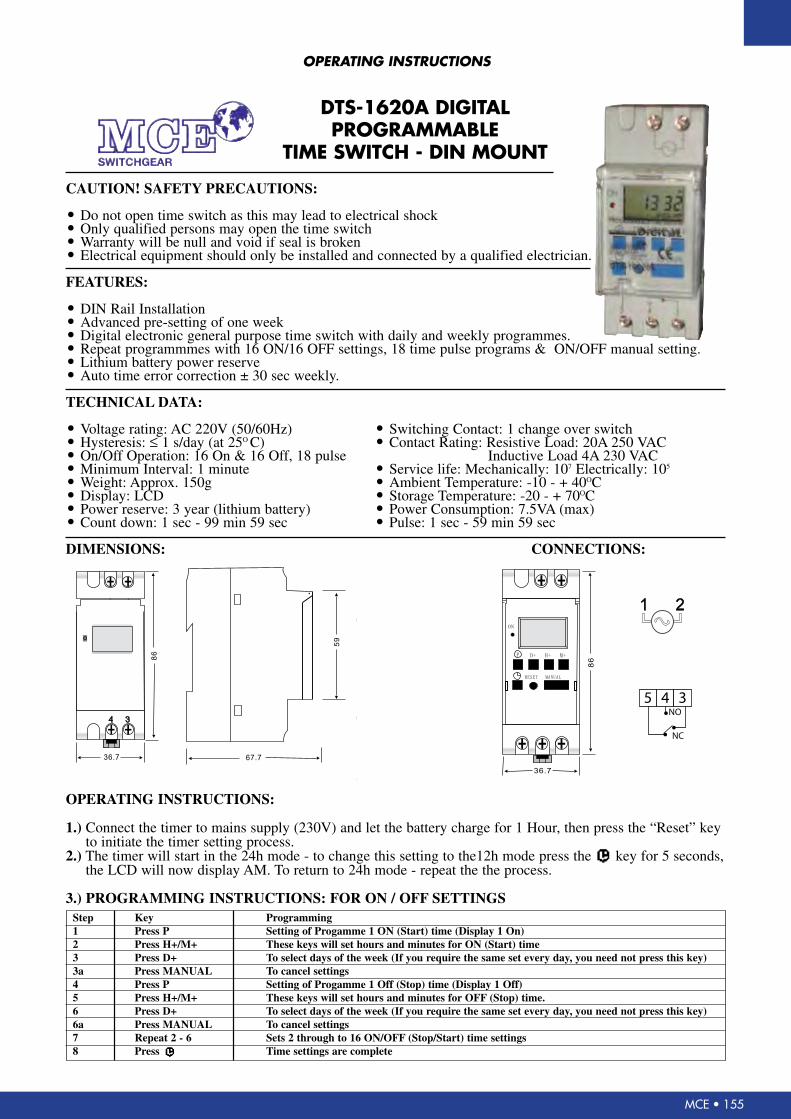
• Do not open time switch as this may lead to electrical shock• Only qualified persons may open the time switch• Warranty will be null and void if seal is broken• Electrical equipment should only be installed and connected by a qualified electrician.
FEATURES:
• DIN Rail Installation• Advanced pre-setting of one week• Digital electronic general purpose time switch with daily and weekly programmes.• Repeat programmmes with 16 ON/16 OFF settings, 18 time pulse programs & ON/OFF manual setting.• Lithium battery power reserve• Auto time error correction ± 30 sec weekly.
TECHNICAL DATA:
• Voltage rating: AC 220V (50/60Hz) • Switching Contact: 1 change over switch• Hysteresis: ≤ 1 s/day (at 25O C) • Contact Rating: Resistive Load: 20A 250 VAC • On/Off Operation: 16 On & 16 Off, 18 pulse Inductive Load 4A 230 VAC• Minimum Interval: 1 minute • Service life: Mechanically: 107 Electrically: 105
• Weight: Approx. 150g • Ambient Temperature: -10 - + 40OC• Display: LCD • Storage Temperature: -20 - + 70OC• Power reserve: 3 year (lithium battery) • Power Consumption: 7.5VA (max)• Count down: 1 sec - 99 min 59 sec • Pulse: 1 sec - 59 min 59 sec
DIMENSIONS: CONNECTIONS:
OPERATING INSTRUCTIONS:
1.) Connect the timer to mains supply (230V) and let the battery charge for 1 Hour, then press the “Reset” keyto initiate the timer setting process.
2.) The timer will start in the 24h mode - to change this setting to the12h mode press the key for 5 seconds,the LCD will now display AM. To return to 24h mode - repeat the the process.
3.) PROGRAMMING INSTRUCTIONS: FOR ON / OFF SETTINGSStep Key Programming1 Press P Setting of Progamme 1 ON (Start) time (Display 1 On)2 Press H+/M+ These keys will set hours and minutes for ON (Start) time3 Press D+ To select days of the week (If you require the same set every day, you need not press this key)3a Press MANUAL To cancel settings4 Press P Setting of Progamme 1 Off (Stop) time (Display 1 Off)5 Press H+/M+ These keys will set hours and minutes for OFF (Stop) time.6 Press D+ To select days of the week (If you require the same set every day, you need not press this key)6a Press MANUAL To cancel settings7 Repeat 2 - 6 Sets 2 through to 16 ON/OFF (Stop/Start) time settings8 Press Time settings are complete
DtS-1620A DiGitAl PrOGrAMMABlE
tiME SWitcH - DiN MOUNt
1 2
4 3
ON
P D+ H+ M+
RESET MANUAL
4 3
86
86
59
36.7
36.7
67.7
CAUTION!SAFETY PRECAUTIONS:
FEATURES:
TECHNICAL DATA:
DIMENSIONS: CONNECTIONS:
OPERATING INSTRUCTIONS:
3.) PROGRAMMING INSTRUCTIONS:FOR ON/OFF SETTINGS
1.)
2.)
Do not open time switch as this may lead to electrical shockOnly qualified persons may open the time switchWarranty will be null and void if seal is brokenElectrical equipment should only be installed and connected by a qualified electrician.
DIN Rail InstallationAdvanced pre-setting of one weekDigital electronic general purpose time switch with daily and weekly programmes.Repeat programmes with 16 ON/16 OFF settings, 18 time pulse programs & ON/OFF manual setting.Lithium battery power reserveAuto time error correction 30 sec weekly.±
Voltage rating:AC 220V (50/60Hz)Hysteresis: < 1 s/day (at 25 )On/Off Operation: 16 On & 16 Off, 18 pulseMinimum Interval: 1 minuteWeight: Approx. 150gDisplay: LCDPower reserve: 3 year (lithium battery)Count down: 1 sec - 99 min 59 sec
℃
Connect the timer to mains supply (230V) and let the battery charge for 1 Hour, then press the Reset key“ ”to initiate the timer setting process.The timer will start in the 24h mode - to change this setting to the 12h mode press the key for 5 seconds,the LCD will now display AM. To return to 24h mode - repeat the the process.
Switching Contact: 1 change over switchContact Rating: Resistive Load: 20A 250 VAC
Inductive Load 4A 230 VACService life: Mechanically: 10 Electrically: 10Ambient Temperature: -10 - + 40Storage Temperature: -20 - + 70Power Consumption: 7.5VA (max)Pulse: 1 sec - 59 min 59 sec
7 5
℃℃
Step
1
2
3
3a
4
5
6
6a
7
8
Key
Press P
Press H+/M+
Press D+
Press MANUAL
Press P
Press H+/M+
Press D+
Press MANUAL
Press 2 - 6
Press
Programming
Setting of Progamme 1 ON (Start) time (Display 1 On)
These keys will set hours and minutes for ON (Start) time
To select days of the week (If you require the same set every day,you need not press this key)
To cancel settings
Setting of Progamme 1 Off (Stop) time (Display 1 Off)
These keys will set hours and minutes for OFF (Stop) time.
To select days of the week (If you require the same set every day, you need not press this key)
To cancel settings
Sets 2 through to 16 ON/OFF (Stop/Start) time settings
Time settings are complete
SWITCHGEAR
GTS-16C20-MRDIGITALGEYSER TIMER SWITCH
5 4 3
NC
NO
156 • MCE
OPERATING INSTRUCTIONS
DTS-16C20A DIGITAL PROGRAMMABLE TIME SWITCH
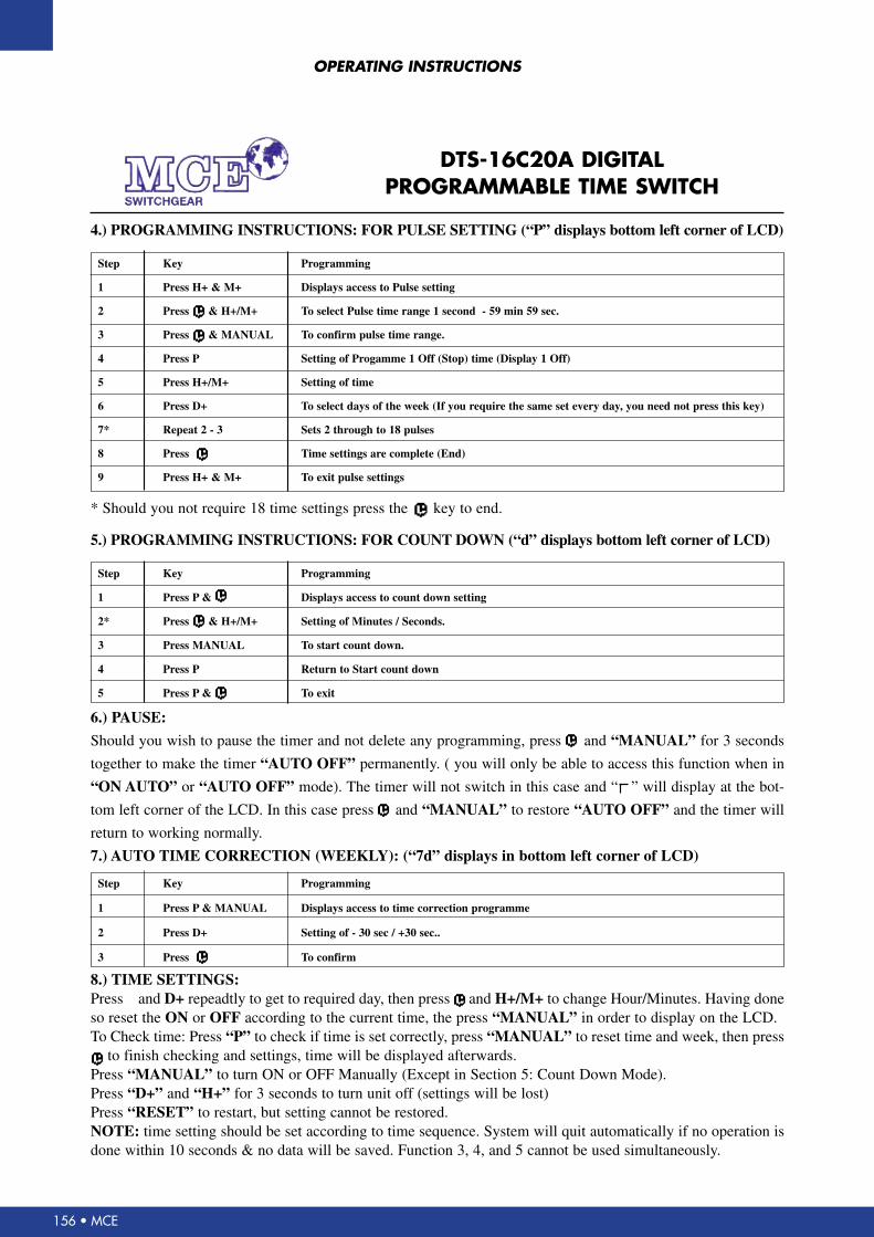
4.) PROGRAMMING INSTRUCTIONS: FOR PULSE SETTING (“P” displays bottom left corner of LCD)
Step Key Programming
1 Press H+ & M+ Displays access to Pulse setting
2 Press & H+/M+ To select Pulse time range 1 second - 59 min 59 sec.
3 Press & MANUAL To confirm pulse time range.
4 Press P Setting of Progamme 1 Off (Stop) time (Display 1 Off)
5 Press H+/M+ Setting of time
6 Press D+ To select days of the week (If you require the same set every day, you need not press this key)
7* Repeat 2 - 3 Sets 2 through to 18 pulses
8 Press Time settings are complete (End)
9 Press H+ & M+ To exit pulse settings
* Should you not require 18 time settings press the key to end.
6.) PAUSE:
Should you wish to pause the timer and not delete any programming, press and “MANUAL” for 3 seconds
together to make the timer “AUTO OFF” permanently. ( you will only be able to access this function when in
“ON AUTO” or “AUTO OFF” mode). The timer will not switch in this case and “ ” will display at the bot-
tom left corner of the LCD. In this case press and “MANUAL” to restore “AUTO OFF” and the timer will
return to working normally.
7.) AUTO TIME CORRECTION (WEEKLY): (“7d” displays in bottom left corner of LCD)
5.) PROGRAMMING INSTRUCTIONS: FOR COUNT DOWN (“d” displays bottom left corner of LCD)
Step Key Programming
1 Press P & Displays access to count down setting
2* Press & H+/M+ Setting of Minutes / Seconds.
3 Press MANUAL To start count down.
4 Press P Return to Start count down
5 Press P & To exit
Step Key Programming
1 Press P & MANUAL Displays access to time correction programme
2 Press D+ Setting of - 30 sec / +30 sec..
3 Press To confirm
8.) TIME SETTINGS:Press and D+ repeadtly to get to required day, then press and H+/M+ to change Hour/Minutes. Having doneso reset the ON or OFF according to the current time, the press “MANUAL” in order to display on the LCD.To Check time: Press “P” to check if time is set correctly, press “MANUAL” to reset time and week, then press
to finish checking and settings, time will be displayed afterwards.Press “MANUAL” to turn ON or OFF Manually (Except in Section 5: Count Down Mode).Press “D+” and “H+” for 3 seconds to turn unit off (settings will be lost)Press “RESET” to restart, but setting cannot be restored.NOTE: time setting should be set according to time sequence. System will quit automatically if no operation isdone within 10 seconds & no data will be saved. Function 3, 4, and 5 cannot be used simultaneously.

MCE • 157
OPERATING INSTRUCTIONS
1 2
4 3
ON
P D+ H+ M+
RESET MANUAL
4 3
86
86
59
36.7
36.7
67.7
CAUTION!SAFETY PRECAUTIONS:
FEATURES:
TECHNICAL DATA:
DIMENSIONS: CONNECTIONS:
OPERATING INSTRUCTIONS:
3.) PROGRAMMING INSTRUCTIONS:FOR ON/OFF SETTINGS
1.)
2.)
Do not open time switch as this may lead to electrical shockOnly qualified persons may open the time switchWarranty will be null and void if seal is brokenElectrical equipment should only be installed and connected by a qualified electrician.
DIN Rail InstallationAdvanced pre-setting of one weekDigital electronic general purpose time switch with daily and weekly programmes.Repeat programmes with 16 ON/16 OFF settings, 18 time pulse programs & ON/OFF manual setting.Lithium battery power reserveAuto time error correction 30 sec weekly.±
Voltage rating:AC 220V (50/60Hz)Hysteresis: < 1 s/day (at 25 )On/Off Operation: 16 On & 16 Off, 18 pulseMinimum Interval: 1 minuteWeight: Approx. 150gDisplay: LCDPower reserve: 3 year (lithium battery)Count down: 1 sec - 99 min 59 sec
℃
Connect the timer to mains supply (230V) and let the battery charge for 1 Hour, then press the Reset key“ ”to initiate the timer setting process.The timer will start in the 24h mode - to change this setting to the 12h mode press the key for 5 seconds,the LCD will now display AM. To return to 24h mode - repeat the the process.
Switching Contact: 1 change over switchContact Rating: Resistive Load: 20A 250 VAC
Inductive Load 4A 230 VACService life: Mechanically: 10 Electrically: 10Ambient Temperature: -10 - + 40Storage Temperature: -20 - + 70Power Consumption: 7.5VA (max)Pulse: 1 sec - 59 min 59 sec
7 5
℃℃
Step
1
2
3
3a
4
5
6
6a
7
8
Key
Press P
Press H+/M+
Press D+
Press MANUAL
Press P
Press H+/M+
Press D+
Press MANUAL
Press 2 - 6
Press
Programming
Setting of Progamme 1 ON (Start) time (Display 1 On)
These keys will set hours and minutes for ON (Start) time
To select days of the week (If you require the same set every day,you need not press this key)
To cancel settings
Setting of Progamme 1 Off (Stop) time (Display 1 Off)
These keys will set hours and minutes for OFF (Stop) time.
To select days of the week (If you require the same set every day, you need not press this key)
To cancel settings
Sets 2 through to 16 ON/OFF (Stop/Start) time settings
Time settings are complete
SWITCHGEAR
GTS-16C20-MRDIGITALGEYSER TIMER SWITCH
GtS-16c20-Mr DiGitAl GEYSEr tiMEr SWitcH - MiNi rAil
MOUNt
MINI
NO
158 • MCE
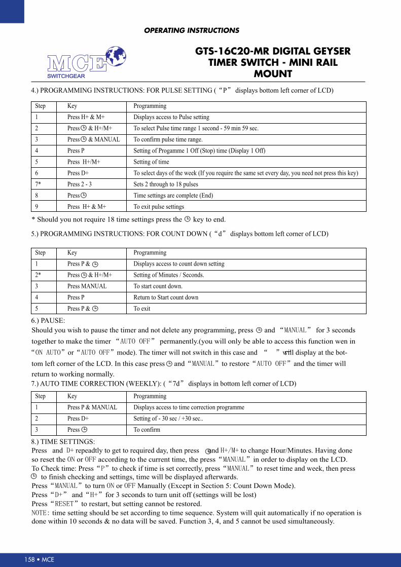
4.) PROGRAMMING INSTRUCTIONS: FOR PULSE SETTING ( P displays bottom left corner of LCD)“ ”
5.) PROGRAMMING INSTRUCTIONS: FOR COUNT DOWN ( d displays bottom left corner of LCD)“�”
6.) PAUSE:
7.) AUTO TIME CORRECTION (WEEKLY): ( 7d displays in bottom left corner of LCD)“ ”
8.) TIME SETTINGS:
Should you wish to pause the timer and not delete any programming, press and for 3 seconds“MANUAL”
* Should you not require 18 time settings press the key to end.
together to make the timer permanently.(you will only be able to access this function wen in“AUTO OFF”
Press and repeadtly to get to required day, then press and to change Hour/Minutes. Having doneD+ H+/M+
so reset the or according to the current time, the press in order to display on the LCD.ON OFF “MANUAL”
To Check time: Press to check if time is set correctly, press to reset time and week, then press“P” “MANUAL”
to finish checking and settings, time will be displayed afterwards.
Press to turn or Manually (Except in Section 5: Count Down Mode).“MANUAL” ON OFF
Press and for 3 seconds to turn unit off (settings will be lost)“D+” “H+”
Press to restart, but setting cannot be restored.“RESET”
NOTE: time setting should be set according to time sequence. System will quit automatically if no operation is
done within 10 seconds & no data will be saved. Function 3, 4, and 5 cannot be used simultaneously.
“ON AUTO” “AUTO OFF” “ ”or mode). The timer will not switch in this case and will display at the bot-
tom left corner of the LCD. In this case press and to restore and the timer will“MANUAL” “AUTO OFF”
return to working normally.
Step
1
2
3
4
5
6
7*
8
9
Step
1
2*
3
4
5
Step
1
2
3
Key
Press H+ & M+
Press & H+/M+
Press & MANUAL
Press P
Press H+/M+
Press D+
Press 2 - 3
Press
Press H+ & M+
Key
Press P &
Press & H+/M+
Press MANUAL
Press P
Press P &
Key
Press P & MANUAL
Press D+
Press
Programming
Displays access to Pulse setting
To select Pulse time range 1 second - 59 min 59 sec.
To confirm pulse time range.
Setting of Progamme 1 Off (Stop) time (Display 1 Off)
Setting of time
To select days of the week (If you require the same set every day, you need not press this key)
Sets 2 through to 18 pulses
Time settings are complete (End)
To exit pulse settings
Programming
Displays access to count down setting
Setting of Minutes / Seconds.
To start count down.
Return to Start count down
To exit
Programming
Displays access to time correction programme
Setting of - 30 sec / +30 sec..
To confirm
SWITCHGEAR
GTS-16C20-MRDIGITALGEYSER TIMER SWITCH
OPERATING INSTRUCTIONS
GtS-16c20-Mr DiGitAl GEYSEr tiMEr SWitcH - MiNi rAil
MOUNt

159 • MCE
KCM1MOULDED CASE CIRCUIT BREAKERSDIMENSIONScircUit BrEAKErS
3 POlE l l1 W H H1 H2 a b ød t1 t2
KcM1-100 150 51 92 87 68 25 30 129 4.5 22 60
KcM1-225 165 64 107 108 87 25 35 126 5.5 25 60
KcM1-400 257 105 140 146 100 36.5 44 215 6.5 53 103
KcM1-630 270 118 182 160 108 41 58 200 7 65 103
KcM1-800 280 102 210 146 103 34.5 70 243 7 65 105
KcM1-1250 406 104 210 190 140.5 58.5 70 375 10 78 98
4 POlE l l1 W1 H H1 H2 a b ød t1 t2
KcM1-100 150 51 122 87 68 25 30 129 4.5 22 60
KcM1-225 165 64 142 108 87 25 35 126 5.5 25 60
KcM1-400 257 105 184 146 100 36.5 44 215 6.5 53 103
KcM1-630 270 118 240 160 108 41 58 200 7 65 103
KcM1-800 280 102 280 146 103 34.5 70 243 7 65 105
OVERALL AND MOUNTING DIMENSIONS FOR MCCB’S
H2
a aa
W W
l1
b bl l
l1
H1
H
t2

160 • MCE
TRIPPING CURVES FOR KCM1MOULDED CASE CIRCUIT BREAKERS
circUit BrEAKErS
cUrVES (FOr POWEr DiStriBUtiON)
Tripping curve of KCM1-100S (16~32)
Tripping curve of KCM1-100S(40~100)
Tripping curve of KCM1-225S
Temperature compensation curve of KCM1-100S (16~32)
Temperature compensation curve of KCM1-100S (40~100)
Temperature compensation curve of KCM1-225S

161 • MCE
TRIPPING CURVES FOR KCM1MOULDED CASE CIRCUIT BREAKERS
circUit BrEAKErS
Tripping curve of KCM1-400S
Tripping curve of KCM1-630S, 800S
Tripping curve of KCM1-1250S
Temperature compensation curve of KCM1-400S
Temperature compensation curve of KCM1-630S, 800S
Temperature compensation curve of KCM1-1250S