oscillating heat pipes (ohp) - college of...
TRANSCRIPT

OSCILLATING HEAT PIPES (OHP)
BY
CHRISTOPHER FASULA A SPECIAL PROBLEMS PAPER SUBMITTED IN PARTIAL FULFILLMENT OF THE
REQUIREMENTS FOR THE DEGREE OF
MASTERS OF SCIENCE
IN
MECHANICAL ENGINEERING AND APPLIED MECHANICS
UNIVERSITY OF RHODE ISLAND
May 2009

i
TABLE OF CONTENTS
1.0 ABSTRACT ....................................................................................................................... 1 2.0 N0MENCLATURE ........................................................................................................... 1 3.0 INTRODUCTION............................................................................................................. 1
3.1 Traditional Heat Pipes..................................................................................................... 1 3.2 Oscillating Heat Pipe (OHP) ........................................................................................... 2 3.3 OHP Design and Operation ............................................................................................ 5 3.4 OHP Performance ........................................................................................................... 7
3.4.1 OHP Resistances ..................................................................................................... 7 3.4.1.1 Contact Resistance, Rcont ..................................................................................... 8 3.4.1.2 Wall Resistance, Rwall ......................................................................................... 9 3.4.1.3 Evaporation Resistance, Revap and Condenser Resistance, Rcond ........................ 9 3.4.1.4 Liquid-Vapor Thermal Resistance, Rl-v .............................................................. 9
3.4.2 OHP Fill Ratio ...................................................................................................... 12 4.0 OHP HEAT TRANSFER CHARACTERISTICS ....................................................... 13
4.1.1 OHP Orientation ................................................................................................... 13 4.2 Heat Transfer Characteristic of an Oscillating Heat Pipe with an Open End ............... 14 4.3 Heat Transfer Characteristic of a Closed End Oscillating Heat Pipe (CEOHP)........... 15
4.3.1 Investigation of a CEOHP at Steady State ............................................................ 16 4.3.1.1 Effects from CEOHP Geometry ....................................................................... 16 4.3.1.2 Effect of Dimensionless Parameters ................................................................. 17 4.3.1.3 Correlation to Predict Heat Flux ....................................................................... 18
4.3.2 Investigation of a CEOHP at Critical State........................................................... 19 4.3.2.1 Effects from CEOHP Geometry ....................................................................... 20 4.3.2.2 Effect of Dimensionless Parameters ................................................................. 20 4.3.2.3 Correlation to Predict Heat Flux ....................................................................... 22
4.4 Heat Transfer Characteristic of a Closed Loop Oscillating Heat Pipe (CLOHP)......... 23 4.4.1 CLOHP without Check Valves ............................................................................. 23
4.4.1.1 Effects from CLOHP Operating Orientation and Geometry ............................ 24 4.4.1.2 Effect of Dimensionless Parameters ................................................................. 27
4.4.2 CLOHP with Check Valves (CLOHP/CV)........................................................... 28 4.4.2.1 Effects from CLOHP/CV Operating Geometry ................................................ 29 4.4.2.2 Effect of Dimensionless Parameters ................................................................. 30
5.0 OHP STARTUP CHARACTERISTICS ...................................................................... 31 5.1 Visualization of OHP Startup ....................................................................................... 32 5.2 Analytical Model for OHP Startup ............................................................................... 34
6.0 PROPOSED APPLICATIONS FOR OSCILLATING HEAT PIPES ...................... 35 7.0 CONCLUSION ............................................................................................................... 36 8.0 BIBLIOGRAPHY ........................................................................................................... 38

ii
LIST OF FIGURES Figure 1 Cross-sectional view of a typical wicked heat pipe [2] .................................................... 2Figure 2 Illustration of an Oscillating Heat Pipe [6] ....................................................................... 3Figure 3 Basic Principle of an Oscillating Heat Pipe (OHP) [5] .................................................... 4Figure 4 Types of OHPs [7] ............................................................................................................ 6Figure 5 OHP Pressure-Enthalpy Diagram [2] ............................................................................... 7Figure 6 OHP Thermal Resistance Components [8] ....................................................................... 8Figure 7 Effects of Orientation on the Performance of a Flat OHP [9] ........................................ 14Figure 8 Heat Flux of a CEOHP vs. Ku [7] .................................................................................. 18Figure 9 Ethanol Slugs and Bubbles in a Glass Tube under Isothermal Conditions [12] ............ 24Figure 10 CLOHP Thermal Performance [12] ............................................................................. 26Figure 11 CLOHP Check Valve [18] ............................................................................................ 29Figure 12 Relationship of Rcv to CLOHP/CV Heat Flux [18] ...................................................... 30Figure 13 Correlation for Predicting CLOHP/CV Heat Flux (vertical position) [18] .................. 31Figure 14 Visualization of Bubble Development and Growth [19] .............................................. 32Figure 15 Schematic of Globe and Column Bubbles [19] ............................................................ 33

1
1.0 ABSTRACT
With the development of higher performance electronic devices, there is a need for better
thermal management. The heat output of these devices can potentially exceed the heat transfer
capabilities of current heat pipe designs. Oscillating Heat Pipes (OHPs) have high heat spreading
performance and are capable of removing higher heat fluxes. OHPs have superior performance
compared to traditional heat pipes and can be used to solve the future electronic cooling
problems.
OHPs are a passive heat transfer device and do not require a pump or additional power to
operate. They also do not need a wicking structure to transport the liquid and can work at higher
heat fluxes. Heat transfer is through natural oscillations of the working fluid between the
evaporator and condenser sections.
This paper is a literature review on OHP technology and work performed by researchers
since the early 1990’s. It investigates the analytical and experimental work performed on the
operating mechanisms of OHPs and their heat transfer characteristics. Many experiments have
been performed to visualize the flow pattern, while numerical models were used to predict the
flow and temperature behavior in an OHP. The advantages and limitation of using OHPs, and
their applications will also be discussed.

1
2.0 N0MENCLATURE
Across – OHP cross sectional area (m2
Bo - Bond Number (Ratio of buoyancy force to surface tension force)
Cp – Constant pressure specific heat (J/kgK)
Di – Internal Diameter (m)
Fr - Froude Number (Ratio of dynamic viscosity to weight)
g - Gravitational acceleration (m/s2)
hfg – Latent heat of vaporization (J/Kg)
Ja – Jacob Number(Ratio of sensible heat to that of the latent heat of the working fluid)
Ka – Karman Number
Ku - Kutateladze Number (Ratio of heat flux to critical heat flux)
L – Length (m)
Le/di – Aspect Ratio
n – Number of turns
Prv - Prandtl Number (Ratio of momentum diffusivity to thermal diffusivity of vapor)
Q – Heat transfer Rate (W) .q - Heat flux (W/m2)
qc – Critical heat flux (W/m2)
R – Gas Constant (J/kg K)
R – Radius (m)
Re – Reynolds Number
Rcv – Check valve ratio
Rcond - Thermal resistance due to condensation at the condenser
Rcont - Thermal resistances associated with the contact resistances due to the surface roughness
Revp - Thermal resistance due to evaporation at the evaporator
Rl-v - Thermal resistance along the heat pipe length
Rwall - Thermal resistances in the wall
∆T – Temperature drop (°C or K)
Wa – Wallis Number
We - Weber Number (Ratio of dynamic force to surface tension)

2
Greek Symbols β – Inclination angle from horizontal axis (radian)
δ – Thickness (m)
κ - Thermal Conductivity (W/m K)
μ – Dynamic Viscosity (Pa s)
ρ – Density (kg/m3)
σ – Surface Tension (N/m)
Subscripts a – Adiabatic Section
c – Condenser Section
crit – Critical Value
e – Evaporator Section
eff- Effective
l – Liquid
n – nucleate point
sat – Saturation Condition
v - Vapor
Acronym List CEOHP - Closed-End Oscillating Heat Pipe
CLOHP - Closed-Loop Oscillating Heat Pipe
CLOHP/CV - Closed-Loop Oscillating Heat Pipe with Check Valves
HP – Heat Pipe
OHP – Oscillating Heat Pipe
PHP – Pulsating Heat Pipe

1
3.0 INTRODUCTION
Oscillating heat pipes (OHP), also referred to as pulsating heat pipes (PHP), are a relatively
new development in the field of heat pipe technology. Originally developed and patented by
Hisateru Akachi in 1990, OHPs consist of a long meandering tube which is heated and cooled at
various points along its length. Their operation is based on the principle of oscillation for the
working fluid and a phase change phenomena in a capillary tube. The diameter of the tube must
be small enough such that liquid and vapor plugs exist. Unlike traditional heat pipes, OHPs do
not need a wicking structure to transport the liquid and can work at higher heat fluxes [1].
3.1 Traditional Heat Pipes Traditional heat pipes are heat transfer devices that are capable of transporting large
quantities of heat using a small difference in temperature. The pipe is initially fully evacuated
and then back filled with enough working fluid to saturate the wick. The pressure inside the pipe
is equal to the saturation pressure associated with the heat pipe temperature. As heat enters the
evaporator, equilibrium is perturbed, which generates vapor at a slightly higher pressure and
temperature. The higher pressure causes vapor to flow along the pipe to the condenser section
where a slightly lower temperature causes the vapor to condense and release its latent heat of
vaporization. The condensed fluid is then pumped back to the evaporator by the capillary forces
developed in the wick structure [2].

2
Figure 1 Cross-sectional view of a typical wicked heat pipe [2]
3.2 Oscillating Heat Pipe (OHP) An OHP is typically a meandering tube comprised of a serpentine channel with capillary
dimension. Initially, the OPH is evacuated and then partially filled with the working fluid.
Effects from surface tension cause the formation of liquid slugs interspersed with vapor bubbles.
As heat is applied to the evaporate section, the working fluid begins to evaporate. This results in
an increase of vapor pressure inside the tube which causes the bubbles in the evaporator zone to
grow and pushes the liquid towards the condenser. As the condenser cools, the vapor pressure
reduces and condensation of bubbles occurs. This process between the evaporator and condenser
section is continuous and results in an oscillating motion within the tube. Heat is transferred
through latent heat of the vapor and through sensible heat transported by the liquid slugs [3].
3
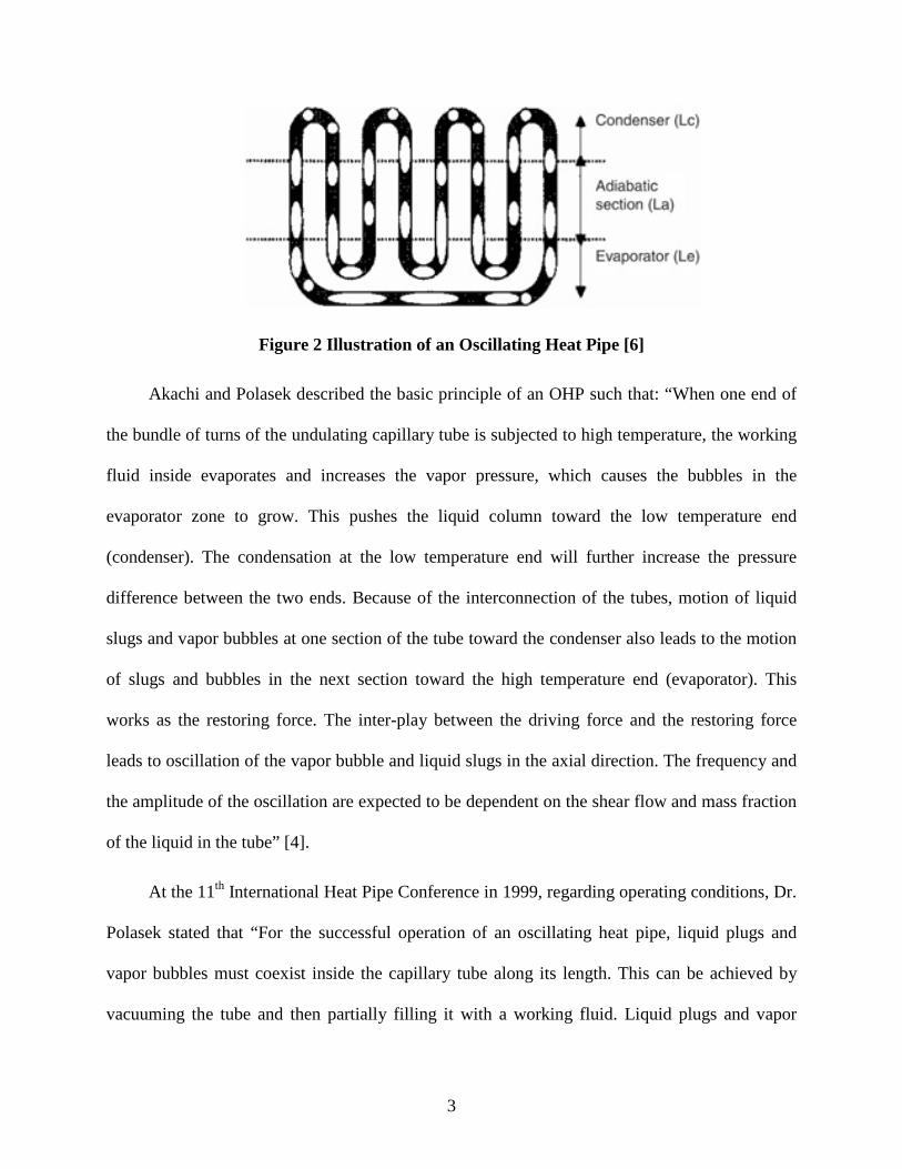
Figure 2 Illustration of an Oscillating Heat Pipe [6]
Akachi and Polasek described the basic principle of an OHP such that: “When one end of
the bundle of turns of the undulating capillary tube is subjected to high temperature, the working
fluid inside evaporates and increases the vapor pressure, which causes the bubbles in the
evaporator zone to grow. This pushes the liquid column toward the low temperature end
(condenser). The condensation at the low temperature end will further increase the pressure
difference between the two ends. Because of the interconnection of the tubes, motion of liquid
slugs and vapor bubbles at one section of the tube toward the condenser also leads to the motion
of slugs and bubbles in the next section toward the high temperature end (evaporator). This
works as the restoring force. The inter-play between the driving force and the restoring force
leads to oscillation of the vapor bubble and liquid slugs in the axial direction. The frequency and
the amplitude of the oscillation are expected to be dependent on the shear flow and mass fraction
of the liquid in the tube” [4].
At the 11th International Heat Pipe Conference in 1999, regarding operating conditions, Dr.
Polasek stated that “For the successful operation of an oscillating heat pipe, liquid plugs and
vapor bubbles must coexist inside the capillary tube along its length. This can be achieved by
vacuuming the tube and then partially filling it with a working fluid. Liquid plugs and vapor

4
bubbles can coexist only when the diameter of the capillary tube is small enough (0.5 to 3 mm).
Another very important condition for the successful operation of an OHP is the connection, in
series, of a bundle of parallel capillary tubes into a single undulating turned tube” [5].
Figure 3 Basic Principle of an Oscillating Heat Pipe (OHP) [5]
Compared to conventional heat pipes, an OHP has the following features:
1. Small pressure drops in the working fluid because most or all of the working fluid
does not flow through the wick structure.
2. Very simple to design and build. The manufacturing costs are very low since wick
structures are not needed in most or all of the OHP sections.
3. The liquid pressure drop caused by the frictional vapor flow can be significantly
reduces the vapor flow direction is the same as liquid flow.
4. The thermally driven, oscillating flow inside the capillary tube will effectively
produce some “blank” surfaces that produce thin-film regions and significantly
enhance evaporating and condensing heat transfer.

5
5. Heat added on the evaporating area can be distributed by the forced convection in
addition to the phase-change heat transfer due to the oscillating motion in the
capillary tube. [5]
3.3 OHP Design and Operation Akachi initially described the phenomenon he observed as a “self-excited” oscillating heat
pipe, as OHPs are a passive two-stage heat transfer device that do not require a mechanical pump
for heat transfer. The main advantages of OHPS are their fast thermal response, high heat
transfer performance, compact size and very simple construction. However, the downside to
OHPS are that their working principle cannot be clearly explained and they unable to
successfully operate at any orientation.
OHPs can be classified into three types, as shown in Figure 4 Types of OHPs [7]. The first
type is the closed-loop oscillating heat pipe (CLOHP), which is connected at both ends of the
tube to form a closed loop. Next is a CLOHP with a check valve which makes the working fluid
move in a specific direction. The last type of OHP is a closed-end oscillating heat pipe
(CEOHP), which is closed at both ends.

6
Figure 4 Types of OHPs [7]
For the case when the OHP is isothermal throughout, the liquid and vapor phases of the
OHP exist in equilibrium at a saturation pressure corresponding to the fixed isothermal
temperature. In Figure 5 OHP Pressure-Enthalpy Diagram [2], point A represents the average
thermodynamic state of the OHP. During operation, there is a temperature gradient between the
evaporator and condenser, which causes a non-equilibrium pressure condition. The heat transfer
to the evaporator causes the bubbles in the evaporator to grow continuously and tries to move to
point B from point A at a higher pressure and temperature. This moves the liquid column
towards the condenser. Simultaneously, the condenser located at the opposite end of the OHP
further enhances the pressure difference between the two points, forcing point A to move to point
C, at a lower pressure and temperature. This results in the development of a non-equilibrium
condition between the driving thermal potentials, with the system trying to stabilize the internal
pressure. Due to the inner-connection of the tube, the motion from the liquid slugs and vapor
bubbles at condenser of one section also leads to the motion of the slugs and bubbles in another

7
section near the evaporator. The interaction between the driving and restoring forces leads to the
oscillation of vapor bubbles and liquid slugs in the axial direction. However, unlike traditional
heat pipes, it is not possible for an operating OHP to reach steady-state pressure equilibrium.
Figure 5 OHP Pressure-Enthalpy Diagram [2]
3.4 OHP Performance The performance on an OHP depends on its structure, shape, material and length. A
major criterion for thermal performance is the temperature drop (∆T) along the heat pipe for a
required heat load, Q, or:
QTRth
∆= (1)
3.4.1 OHP Resistances The overall resistance is composed of several components, starting from the evaporator to
the condenser, as shown in Figure 6 OHP Thermal Resistance Components. There are two
conductive thermal resistances in the wall (Rwall), thermal resistance due to the evaporation and
condensation at the evaporator and condenser (Revp and Rcond), and a thermal resistance along the

8
heat pipe length (Rl-v), which includes the conductive thermal resistance along the wall and the
thermal resistance due to fluid head capabilities, and two thermal resistances (Rcont) which are
associated with the contact resistances due to the surface roughness. It is important to note, that
for wicked heat pipes, additional thermal resistance needs to be added to the wall resistance to
compensate for the wick structure.
Figure 6 OHP Thermal Resistance Components [8] The heat transfer capacity, Q, for an OHP can be estimated as:
crosseff
effcontvlcondevapwallAk
LT
RRRRRTQ
−
∆=
++++∆
=− 22
(2)
Where ∆T is the overall temperature difference between the heating and cooling section, keff and
Leff are the effective thermal conductivity and length and Across is the cross sectional area of the
OHP. A design goal of an OHP is to minimize all the resistances in equation (2) in order to
obtain maximum heat throughout the OHP for a given ∆T.
3.4.1.1 Contact Resistance, Rcont A properly mounted OHP introduces small thermal contact resistances, but the
conductive resistance forces in the wall are negligible. However, both the contact and

9
conductive resistances are almost independent of the heat pipe operating temperatures.
Therefore, the thermal resistance due to the evaporation in the evaporator, Revp, two-phase flow
along the pipe, Rl-v, and the condensation in the condenser, Rcond are critical to the performance
of the heat pipe [2]. For optimal heat transfer performance, the contact resistance should be
decreased.
3.4.1.2 Wall Resistance, Rwall Both the conductive thermal resistance in the wall and the high thermal conductivity of
the wall material are negligible.
3.4.1.3 Evaporation Resistance, Revap and Condenser Resistance, Rcond The thermal resistance due to the evaporation in the evaporator and the condensation in
condenser are critical parameters for optimal OHP performance. The two-phase flow develops
in the evaporator and moves towards the condenser, where the bubbles collapse and release their
latent heat of vaporization. Extensive research has been conducted to estimate the flow boiling
heat transfer coefficient in an OHP. The data covers a range of channel diameter from 0.5 mm to
2.92 mm and heat flux from 25 kW/m2 to 700 kW/m2. The flow boiling heat transfer coefficients
reported ranged from 1000 W/(m2 x °C) and 8500 W/(m2 x °C). Using these results, the
corresponding thermal resistance in the OHP evaporator and condenser can be estimated
between (0.001/A) °C/W and 1.18x10⁻⁴/A °C/W [8].
3.4.1.4 Liquid-Vapor Thermal Resistance, Rl-v The liquid-vapor thermal resistance is the most important parameter for optimal OHP
performance and is a function of the pressure/temperature state conditions between the
evaporator and condenser. This resistance determines the OHP transfer rate and depends on the
following effects [8]:

10
1. Number of turns – The number of turns should be maximized to increase the heat
transfer rate and spatial orientation of the OHP.
2. Filling ratio – The filling ratio is defined as the fraction by volume of the heat
pipe, which is initially filled with the liquid. The optimal filling ratio is
determined experimentally when the maximum heat transfer rate is achieved at a
given temperature.
3. Effect of evaporator/condenser section size – As a rule of thumb, the condenser
area should be larger than the evaporator area to avoid evaporator dry out. The
evaporator and condenser should be designed for the specific application.
4. Inclination angle – The inclination angle is determined experimentally when the
maximum heat transfer rate is achieved at a given temperature.
5. Working fluid – The working fluid should be selected such that it supports the
OHP operating temperature range, which can typically range from 50 to 150°C.
Within this range several different working fluids may exist. When selecting a
working fluid, the following working fluid characteristics should be examined:
a. Compatibility with the OHP material(s)
b. Thermal stability
c. Wettability
d. Reasonable vapor pressure
e. High latent heat and thermal conductivity
f. Low liquid and vapor viscosities

11
g. Acceptable freezing point
For most applications, the thermodynamic characteristics of water make it a good
choice for OHP applications, as it has high latent heat, which spreads more heat
with less fluid flow, and high thermal conductivity which minimizes ∆T.
However, water does have high surface tension and may have adverse effects on
the OHP as it may cause additional friction and limit the two-phase flow
oscillations of the OHP. Methanol is a good substitution for water, especially for
sub zero applications, as it has approximately one third the surface tension [2].
6. Tube/channel cross sectional diameter – The internal diameter directly affects the
OHP. A larger hydraulic diameter results in a lower wall thermal resistance and
increases the effective thermal conductivity. The capillary tube inside diameter
must be small enough such that:
( )vlgD
ρρσ−
= 2max (3)
Where:
σ is the working fluid surface tension
g is the gravitational acceleration
ρl is the liquid density
ρv is the vapor density
If D < Dmax, surface tension forces dominate and stable liquid plugs are formed.
However, if D > Dmax, the surface tension is reduced and the working fluid will
stratify by gravity and oscillations will cease. The OHP may operate as an
interconnected array of two-phase thermosyphons [2].

12
3.4.2 OHP Fill Ratio The fill ratio is defined as the fraction by volume of the heat pipe, which is initially filled
with the liquid. There are two distinct operational fill ratio limits, 0% and 100%. At 0%, the
OHP is in a pure conduction mode and has a very high undesirable thermal resistance. For this
case there is not enough working fluid for the formation of distinct slugs and there is a tendency
for evaporator dry out to occur. At 100%, there are very few bubbles present which causes the
OHP to operate as a single phase thermosyphon. While under this condition, oscillations do not
occur, but substantial heat can still be transferred due to the liquid circulation in the pipe by
thermally induced buoyancy. The thermosyphon action is maximum for an OHP in a vertical
orientation and stops in the a horizontal orientation [2].
In addition, to the operational fill ration limits, there are three distinct operational fill
ratio regions, near 100%, near 0% and the OHP true working range. For the case of near 100%
filled the working fluid inside the OHP cannot form enough bubbles to generate the required
perturbations, hindering the performance of the OHP. Even buoyancy induced liquid circulation
is hindered from the added surface tension from the bubbles. For the near 0% case, there is not
enough liquid present in the OHP to form enough distinct slugs. Under this condition, there is
also a tendency for the evaporator to dry out. The optimal performance for an OHP is somewhere
between these two extremes, which is known as the OHP true working range. For this, the filled
ratio is usually somewhere between 20% and 70%, which causes a two-phase flow to develop
and allows the OHP to act as a true oscillating device.
The exact working range will differ for various working fluids, operating parameters and
constructions. A lower fill ratio will produce more bubbles and increases the intensity of
oscillations, but there is also less liquid mass for sensible heat transfer. Conversely, a higher fill

13
ratio will generate fewer bubbles, reducing the perturbations and reducing the overall
performance of the OHP [2]. Therefore, there needs to be a balance for optimal OHP
performance.
4.0 OHP HEAT TRANSFER CHARACTERISTICS Since the late 1990s, numerous experimental and numerical/analytical investigations have
been conducted by researchers to better understand OHPs. These investigations have focused on
the mechanisms behind OHPs as well as the heat transfer characteristics. Many experiments have
been performed to visualize the flow pattern, while numerical models are used to predict the flow
and temperature behavior in an OHP. As mentioned previously, there are three distinct types of
OHPs. An analysis of the heat transfer characteristics for each device will be discussed in the
following sections.
4.1.1 OHP Orientation Xu et al. [9] experimentally investigated the thermal performance using a flat oscillating
heat pipe sample made out of aluminum. They reported that the cooling temperature and
cooling surface area in the condensation section have a relatively low impact on the
performance of the heat pipe, while the orientation, heating area and working fluid have a big
influence on the overall OHP performance. Four heating modes were studied, including heating
a vertically oriented heat pipe from both the top and bottom, as well as heating a horizontally
oriented heat pipe from the bottom and side.
Their experimental results showed that gravity does have an impact on the performance of
the flat OHP. The OHP exhibited its lowest thermal performance when it was heated from the
bottom and the worst overall performance when it was heated from the top. As power increased,

14
the performance difference between the heating modes decreased. Gravity had a minimal effect
on the thermal performance of the OHP in the horizontal heating mode. However, it does play
an important role in the pressure distribution along the heat pipe due to the pressure difference
between the evaporator and condenser. These results can be seen in Figure 7 Effects of
Orientation on the Performance of a Flat OHP [9].
Figure 7 Effects of Orientation on the Performance of a Flat OHP [9]
4.2 Heat Transfer Characteristic of an Oscillating Heat Pipe with an Open End Zhang et al. [10] modeled the heat transfer of an OHP with an open end by analyzing thin
film evaporation and condensation. The evaporator section of the heat pipe was closed while the
condenser section of the heat pipe was left open. As the liquid slug moves towards the open end,
the trailing edge of the liquid plug leaves a thin liquid film on the wall of the pipe. The
evaporation and condensation over the thin film is the driving force behind the oscillating flow.
To properly model the heat transfer and oscillating flow, the following assumptions were made:
1. The vapor is saturated and there is no temperature gradient in the vapor region

15
2. Heat transport in the thin liquid films is only due to the conduction in the radial
direction
3. Inertia terms can be neglected for viscous flow in the liquid films since the
Reynolds number is low
4. Shear stress at the liquid-vapor interface is negligible
5. The interfacial thermal resistance is negligible compared with the thermal
resistance of the liquid film
The heat transfer solutions were applied to the thermal model and a parametric study was
performed. From the results, it can be concluded that while the total heat transfer in an OHP is
composed of both latent and sensible heat, the contribution of sensible heat on the total heat
transfer is significantly larger than that of latent heat. In addition, the surface tension has a
negligible impact on the frequency and amplitude of the oscillation after steady oscillation has
been reached.
4.3 Heat Transfer Characteristic of a Closed End Oscillating Heat Pipe (CEOHP) The advantages of a CEOHP are its heat transferring properties in any orientation, its quick
response and its internal wickless structure. Out of all the types of OHPs, CEOHPs are the least
complicated operating mechanism. Experimental investigations have been conducted to
systematically investigate the heat transfer characteristics of a CEOHP at both steady and
critical states. The results for both will be discussed in the following sections.
The heat transfer in a CEOHP is such that, as heat is supplied at the evaporator, the vapor
bubbles originate in the evaporator section through latent heat. These bubbles move to the
condenser with buoyancy force producing pumping action. Most of the bubbles that flow into

16
the condenser section collapse and the latent heat is released. The heat is transferred through a
phase change which is independent of temperature difference. The heat flux depends only on the
evaporation, buoyancy force and condensation mechanism. [7].
4.3.1 Investigation of a CEOHP at Steady State Rittidech et al. [7] experimentally investigated the heat transfer characteristics of a
CEOHP at steady state using an experimental setup consisting of a CEOHP with a heating bath
as the evaporator and a cooling bath for the condenser. The intent of the investigation was to
study the effects of the internal diameter, evaporator length, number of turns and the
dimensionless parameters on the heat transfer characteristics of a CEOHP in a horizontal
orientation.
4.3.1.1 Effects from CEOHP Geometry From the experiments it was noted that the inner diameter must be less than the
maximum inner diameter found using equation (3), and greater than the inner diameter found
experimentally, or the CEOHP will not be able to transfer heat. It was also concluded tat the
larger the inner diameter, the higher the heat flux.
For the experiment, the evaporator, adiabatic and condenser sections were all of equal
length since the heat flux at the input was equal to the heat flux at the output of the CEOHP. It
was observed that as the evaporator length increased, the heat flux decreased for all working
fluids. It was concluded that as the evaporator length decreased, the effective length between the
condenser and evaporator also decreases, which allows the heat to be efficiently transferred by
the working fluid.
The effect of the number of turns (n) on the heat flux of a CEOHP in a horizontal
orientation was also considered. It was shown, that the number of turns has a direct effect on the
17
heat flux. From the study it was noted that the maximum heat flux for R123 and ethanol were
obtained using a CEOHP with 14 turns. Comparing these results to similar experiments, it can be
concluded that if there is an optimal number of turns, the heat flux will increase and then
decrease with an increase in the number or turns, n.
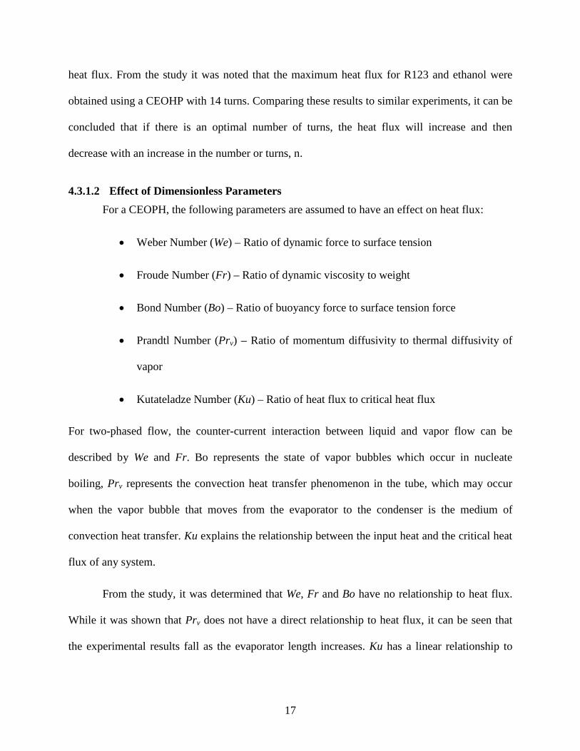
4.3.1.2 Effect of Dimensionless Parameters For a CEOPH, the following parameters are assumed to have an effect on heat flux:
• Weber Number (We) – Ratio of dynamic force to surface tension
• Froude Number (Fr) – Ratio of dynamic viscosity to weight
• Bond Number (Bo) – Ratio of buoyancy force to surface tension force
• Prandtl Number (Prv) – Ratio of momentum diffusivity to thermal diffusivity of
vapor
• Kutateladze Number (Ku) – Ratio of heat flux to critical heat flux
For two-phased flow, the counter-current interaction between liquid and vapor flow can be
described by We and Fr. Bo represents the state of vapor bubbles which occur in nucleate
boiling, Prv represents the convection heat transfer phenomenon in the tube, which may occur
when the vapor bubble that moves from the evaporator to the condenser is the medium of
convection heat transfer. Ku explains the relationship between the input heat and the critical heat
flux of any system.
From the study, it was determined that We, Fr and Bo have no relationship to heat flux.
While it was shown that Prv does not have a direct relationship to heat flux, it can be seen that
the experimental results fall as the evaporator length increases. Ku has a linear relationship to

18
heat flux. Therefore, Prv and Ku can be used to formulate the correlation to predict the heat flux
of a CEOHP in a horizontal orientation, as shown in Figure 8 Heat Flux of a CEOHP vs. Ku [7].
Figure 8 Heat Flux of a CEOHP vs. Ku [7]
4.3.1.3 Correlation to Predict Heat Flux The correlation to predict the heat flux of a horizontal CEOHP, is such that:
116.0
252.0
5.04.4
1.03.4
Pr0052.0
= −
−
vl
v
e
tio n
LLD
Kuρρ
(4)
Where 4.4
1.03.4
e
ti
LLD indicates the size of the CEOHP. For example, if it was very high then the tube
would be larger and the evaporator section would be short, resulting in a high heat flux. If the
value was low, then the tube would be small and the evaporator section would be long with a low
heat flux. n indicates the number of turns or the number of capillary tubes connecting the

19
evaporator and condenser sections. For a low Prv the heat transfer of the vapor slug will be much
higher than its momentum transfer, i.e. the vapor slug will be able to transfer the thermal energy
to condenser section efficiently. ρv/ρl indicates the vapor and liquid density ratio at the working
pressure of the working fluid.
Equation (4) can be used to predict the heat flux of a horizontal CEOHP, with a standard
deviation of ± 30%. However, this equation does not include the parameters of oscillation and
circulation phenomena within the CEOHP. This is an area for future research.
4.3.2 Investigation of a CEOHP at Critical State Katpradit et al. [11] went a step further than Rittidech et al. [7] and investigated the heat
transfer characteristics of a horizontal CEOHP at critical state. Critical state is the point at
which evaporator dryout occurs. It is believed that when an OHP receives an increasing amount
of heat, the internal vapor pressure subsequently increases. If the vapor pressure is too high, the
liquid slugs will be retarded and prevented from returning back to the evaporator section,
causing the internal thermal resistance to rapidly increase. This prevents the heat from the
evaporator from being transferred to the condenser causing the dryout to occur in the
evaporator.
Using a similar experimental setup as Rittidech et al. [7], Katpradit et al. [11] used R123,
ethanol and water to understand the effect of thermo-physical properties of the working fluid.
The results of the experiment showed that for a CEOHP with a high number of turns, dryout
phenomenon first occurred at the evaporator section in a turn close to one of the sealed ends of
the tube. After more heat was supplied, dryout occurred anywhere within the evaporator section.
Similarly, dryout also occurred anywhere within the evaporator for a CEOHP with a small
number of turns.

20
For the study, the critical heat flux was calculated at the point where the first dryout
occurred and was detected by monitoring the temperature in the evaporator section. When the
critical state was reached, the temperature in the tube rapidly increased, due to the liquid at the
condenser not being able to return to the evaporator section. This increases the thermal
resistance and forces the CEOHP to stop operating. From the study, it can be concluded that the
critical heat flux decreases when the section length increases and the critical heat flux increases
as the latent heat of vaporization increases.
4.3.2.1 Effects from CEOHP Geometry For the experiment, the evaporator and condenser were of equal length and the heat flux
at the evaporator and condenser was also equal. It was shown that as the evaporator length
increased, the critical heat flux for all the working fluids decreased at both 0 and 90° operating
orientations. A possible explanation for this is that when the section length increases, the vapor
plug that forms inside the tuber is longer (liquid at the vapor-liquid interface quickly evaporates)
and the vapor bubbles do not easily move to the condenser section. In addition, the liquid inside
the vapor bubbles will quickly evaporate to the condenser section and hold the liquid that returns
from the condenser back to the evaporator. Since there is an insufficient amount of liquid in the
evaporator section, dryout occurs.
4.3.2.2 Effect of Dimensionless Parameters The dimensionless parameters that affect the critical heat flux for a CEOHP depend on its
orientation. For a CEOHP operating at 0° the dimensionless parameters are Ku, Di/Le, Ja and Bo
whereas, for a CEOHP operating at 90° the dimensionless parameters are Ku, Di/Le, Ja, Bo and
1+(ρv/ρl)0.25.

21
When the heat was applied to the tube in the evaporator section at 0° operating
orientation, nucleate boiling occurred within the tube and the vapor bubbles combined together.
As the amount of applied heat is increased, the pressure within the tube increased. This caused
the vapor to form into longer slugs making it difficult to move to the condenser section. As a
result, there is an insufficient amount of liquid in the evaporator section leading to evaporator
dryout. It was found that the dimensionless parameters that affected the critical heat flux of the
CEOHP operating horizontally can be written such that:
= BoJaL
DifKue
,,0 (5)
Conversely, the flow phenomenon for a CEOPH operating at 90° is much different than
at 0°. For the case of 90°, as heat was applied to the evaporator section, nucleate boiling occurred
and the vapor slugs departed from the evaporator to the condenser section. As the applied heat
increased, the interfacial liquid between the liquid and vapor within the tube quickly evaporated
with longer vapor bubbles. If the applied heat continues to increase, the vapor will travel with a
high enough velocity to prevent the interfacial liquid from returning to the condenser. This
causes flooding to occur and the CEOHP can no longer operate due to an insufficient amount of
liquid in the evaporator section.
The dimensionless analysis for the CEOHP operating vertically is similar to that of the
CEOHP operating horizontally, except for the addition of the Wallis Number, Wa. The Wallis
Number (1+(ρv/ρl)0.25) can be used to explain the flooding phenomenon that influences dryout to
occur at the evaporator section and is derived fro the vapor velocity and the vapor pressure
within the tube. Similarly, it was found that the dimensionless parameters that affected the
critical heat flux of the CEOHP operating vertically can be written such that:

22
= WaBoJaL
DifKue
,,,90 (6)
4.3.2.3 Correlation to Predict Heat Flux Based on the effects of the dimensionless parameters on the critical heat flux of a
CEOHP, it is possible to develop a correlation to predict the critical heat flux at both horizontal
and vertical heat modes. The heat transfer of a CEOHP at horizontal heat mode is such that:
( )32.15.0417.1127.1
860,53−
−
×
∆×
×=
σρρ vl
fgeo
gDi
hTCp
LDiKu (7)
From equation (7), it can be seen that the most influential dimensionless parameter on Ku0
is
∆
fghTCp . This is due to the fact that at horizontal operation, the heat transfer is dominated by
the vaporization of liquid and vapor movement to the condenser section. As the applied heat is
continually increased, the liquid film becomes thinner and thinner and critical state is reached.
For a CEOHP at vertical heat mode correlation to predict the critical heat flux is such
that:
( )06.1325.059.05.0212.092.0
9 1002.0
+×
−
×
∆×
×=
−−
l
vvl
fgeo
gDi
hTCp
LDiKu
ρρ
σρρ
(8)
From equation (8), it can be seen that the most influential dimensionless parameter on Ku90 is
25.0
1
+
l
v
ρρ which represents the flooding inside the CEOHP.
Comparing the heat flux predicted using equations (7) and (8) to the experimental data,
equation (7) has a standard deviation of ±18% and ±29% for equation (8). It should be noted that
equations (7) and (8) do not include the circulation phenomena of the internal working fluid. To

23
fully understand the operation of a CEOHP at critical state, internal flow visualization
experiments are needed.
4.4 Heat Transfer Characteristic of a Closed Loop Oscillating Heat Pipe (CLOHP)
A Closed Loop Oscillating Heat Pipe (CLOHP) operates under the same principle as the
other OHPs previously discussed. It consists of a long capillary tube bent with n number of turns.
However, unlike other OHPS, the ends of the CLOHP are joined to form a closed loop. A
CLOHP may or may not contain at least one check valve in its loops. The check valves are a
direction-control device restricting the working fluid to circulate in one direction only.
The CLOHP tends to have better thermal performance than other OHP devices due to the
possibility of fluid circulation. While the addition of check valves increases the heat transfer
capability of the device, the miniaturization of the device makes it difficult and expensive to
install. Experimental investigations have been conducted to systematically investigate the heat
transfer characteristics of a CLOHP with and without check valves. The results for both will be
discussed in the following sections.
4.4.1 CLOHP without Check Valves Charoensawan et al. [12, 13, 17], Khandekar et al. [14], Dmitrun et al. [15] and Yang et
al. [16] experimentally studied the quantitative parameter dependency of CLOHPs. By
measuring the volumetric flow rate as well as the inlet and outlet temperature of the coolant
flowing through the condenser section, it is possible to calculate the heat transfer rate for the
CLOHP. The results of the experiments will be discussed in detail below.
24
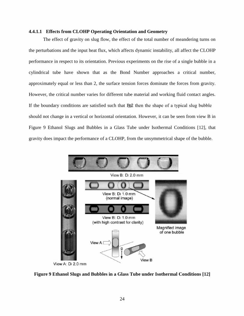
4.4.1.1 Effects from CLOHP Operating Orientation and Geometry The effect of gravity on slug flow, the effect of the total number of meandering turns on
the perturbations and the input heat flux, which affects dynamic instability, all affect the CLOHP
performance in respect to its orientation. Previous experiments on the rise of a single bubble in a
cylindrical tube have shown that as the Bond Number approaches a critical number,
approximately equal or less than 2, the surface tension forces dominate the forces from gravity.
However, the critical number varies for different tube material and working fluid contact angles.
If the boundary conditions are satisfied such that Bo≤2 then the shape of a typical slug bubble
should not change in a vertical or horizontal orientation. However, it can be seen from view B in
Figure 9 Ethanol Slugs and Bubbles in a Glass Tube under Isothermal Conditions [12], that
gravity does impact the performance of a CLOHP, from the unsymmetrical shape of the bubble.
Figure 9 Ethanol Slugs and Bubbles in a Glass Tube under Isothermal Conditions [12]
25
Yang et al. [16] experimentally studied the operational limitations of CLOHPs using
R123 as the working fluid with 1 and 2 mm tubing and 30%, 50% and 70% fill ratios. The results
showed that for an inner diameter of 2 mm, the best performance was for a CLOHP in the
vertical orientation that was heated from below while for an inner diameter of 1 mm orientation
had a negligible impact. The optimal filling ratio was determined to be 50% for both.
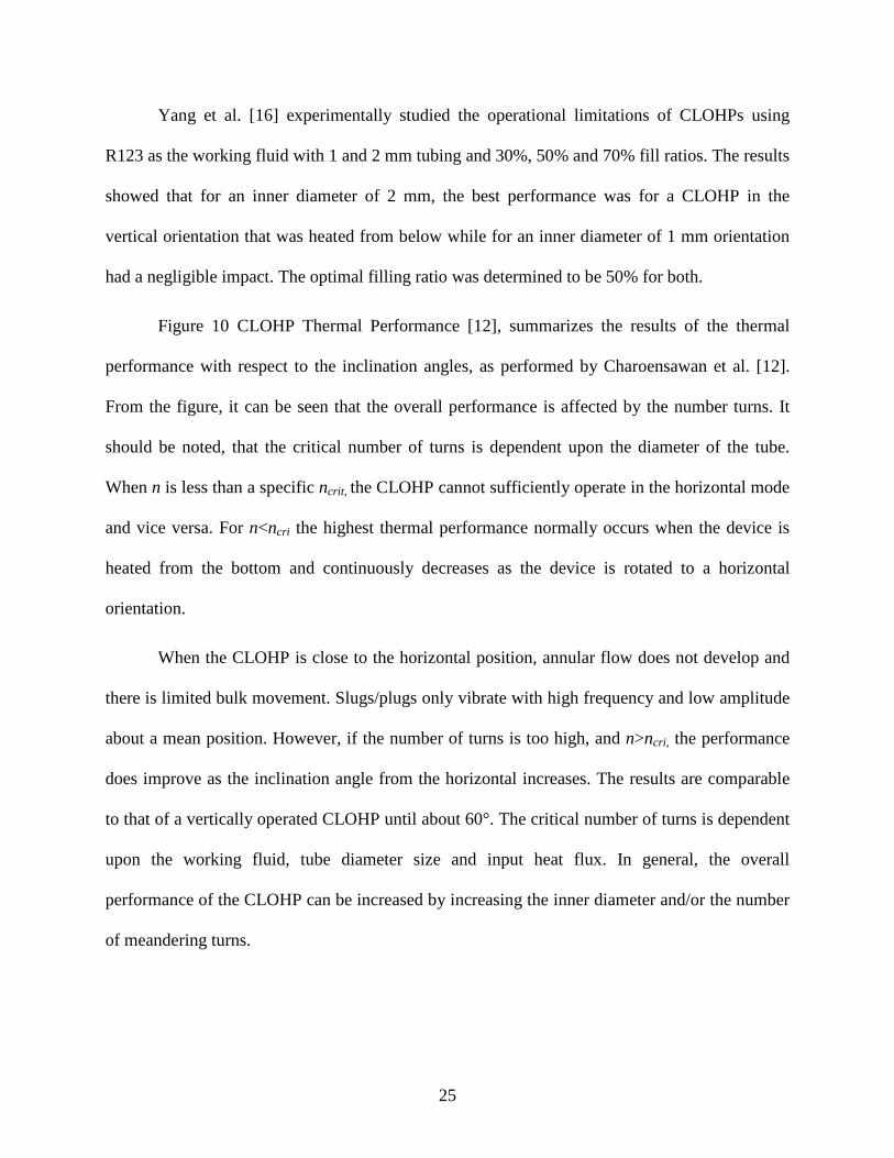
Figure 10 CLOHP Thermal Performance [12], summarizes the results of the thermal
performance with respect to the inclination angles, as performed by Charoensawan et al. [12].
From the figure, it can be seen that the overall performance is affected by the number turns. It
should be noted, that the critical number of turns is dependent upon the diameter of the tube.
When n is less than a specific ncrit, the CLOHP cannot sufficiently operate in the horizontal mode
and vice versa. For n<ncri the highest thermal performance normally occurs when the device is
heated from the bottom and continuously decreases as the device is rotated to a horizontal
orientation.
When the CLOHP is close to the horizontal position, annular flow does not develop and
there is limited bulk movement. Slugs/plugs only vibrate with high frequency and low amplitude
about a mean position. However, if the number of turns is too high, and n>ncri, the performance
does improve as the inclination angle from the horizontal increases. The results are comparable
to that of a vertically operated CLOHP until about 60°. The critical number of turns is dependent
upon the working fluid, tube diameter size and input heat flux. In general, the overall
performance of the CLOHP can be increased by increasing the inner diameter and/or the number
of meandering turns.

26
Figure 10 CLOHP Thermal Performance [12]

27
4.4.1.2 Effect of Dimensionless Parameters Using the experimental results from [12], it can be seen that the type and magnitude of
flow is influenced by the geometry, inclination angle of operation (β), thermo-physical properties
of the working fluid and by the applied heat flux, which is a function of n, Le, and Bo. As
mentioned in the previous section, if Bo is greater than a specified critical Bo, then the working
fluid will settle due to gravity and will no longer act as an OHP, rather it will operate as a two-
phase thermosyphon. Based on these parameters, Khandekar et al. [14] derived an equation for
the maximum heat transfer achievable for a given CLOHP (with filling ratio = 50%) such that:
( )( ) srliq
qp
i
JaKaCLenD
Qq Prexp2 1
..
βπ
=
⋅⋅⋅= (9)
Where:
( ) ( )
( )
∆⋅=
⋅=
+=
⋅
⋅∆⋅=⋅=
−cesatliqp
fg
liq
liqliqpliq
aceeffeffliq
iliqliqliqliq
TC
hJa
kC
LLLLwhereL
DPfKa
,
,
2
22
Pr
5.0Re
µ
µρ
(10)
If Bo≥Bocrit, stable slugs will not form and oscillations will not occur. Therefore, equation (10)
should only be used if Bo≤Bocrit. Correlating equation (10) to the results obtained from the
experiments performed by Charoensawan et al. [12] can be seen in equation (11).
( )( ) 27.043.127.047.048.0
..
Prexp54.02
−=
⋅⋅⋅= nJaKa
LenDQq liq
i
βπ
(11)

28
4.4.2 CLOHP with Check Valves (CLOHP/CV) Closed Loop Oscillating Heat Pipes with Check Valves (CLOHP/CV) provide a high rate
of heat transfer through the addition of one or more check valves with prevents bidirectional
flow. Under normal OHP operating conditions, the liquid and vapor are effectively located in the
condenser and evaporator respectively. The liquid forms U-shaped columns in individual turns of
the OHP and the oscillations form waves. Under these conditions, the effective heat-transfer is
limited by the amplitude of the waves. When the amplitude of oscillatory flow is sufficient and
the heat transfer area is not included as part of the waves, the effective working fluid supply to
the heat transfer area cannot be obtained and the heat transfer is not maintainable [18]. This
operating limit can be overcome by the implementation of check valves in the CLOHP design.
The check valves regulate the flow such that it becomes unidirectional and the heat transfer area
in not restricted by the amplitude of the oscillating flow.
The check valves themselves, are a floating type of valve consisting of a stainless steel
ball and copper tube. Within the tube are a conical valve seat at bottom and a ball stopper at the
top. The ball is free to move between the valve seat and stopper, but when it is in contact with
the valve seat it prevents reverse flow of the working fluid, as shown in Figure 11 CLOHP
Check Valve [18].

29
Figure 11 CLOHP Check Valve [18]
4.4.2.1 Effects from CLOHP/CV Operating Geometry Rittidech et al. [18] studied the heat transfer characteristics of a vertically oriented
CLOHP/CV with 40 turns, an inner diameter of 2.03 mm and different working fluids. Part of
the experiment was to determine the effect from the ratio of check valves on the overall heat
flux. The ratio of check valves, Rcv, is defined as the number of turns divided by the of check
valves. The experiment tested a CLOHP with 2, 5, 8 and 20 valves. From the results, it can be
concluded that the greater the ratio of check valves, the higher the heat flux and that the
maximum heat flux of each working fluid was obtained at the maximum ratio of check valves.
This is due to the fact that an increase in the ratio of check valves, which occurs as the number of
check valves decreases, the effect from gravity on the ball also decreases. This result is shown in
Figure 12 Relationship of Rcv to CLOHP/CV Heat Flux [18].

30
Figure 12 Relationship of Rcv to CLOHP/CV Heat Flux [18] Another key parameter of the experiment was the effect from the aspect ratio, or Le/di on
heat flux. For a 50% fill ratio, the maximum heat flux was obtained at 28 for a diameter of 1.77
and 2.03 mm. From the experiment, it can be concluded that as the aspect ratio increases, the
heat flux decreases.
4.4.2.2 Effect of Dimensionless Parameters The dimensionless parameters assumed to have an effect on the heat flux for a
CLOHP/CV in a vertical mode are the ratio or the check valve, Rcv, aspect ratio, Le/di, Bond
Number, Bo, Weber Number, We, Froude Number, Fr, Jacob Number, Ja, Prandtl Number, Pr,
(ρv/ρl) and Kutateladze Number, Ku. These parameters can be used to formulate a correlation for
the heat flux of a CLOHP/CV in a vertical position such that:
107.05.08.04.1
98.002.12.142.12.2
90 Pr0004.0
=
i
ecv
l
vd
LWeRJaFrBoKu ρρ (12)

31
Comparing these results to the experimental data, as shown in Figure 13 Correlation for
Predicting CLOHP/CV Heat Flux (vertical position) [18], the standard deviation is ±30%.
Therefore equation (12) can be used to predict the heat flux of a CLOHP/CV in a vertical
position.
Figure 13 Correlation for Predicting CLOHP/CV Heat Flux (vertical position) [18]
5.0 OHP STARTUP CHARACTERISTICS The startup characters of an OHP are critical for the development of stable oscillating
motion and are directly related to the performance of the device. These parameters include wall
surface condition, evaporation in the evaporator section, heat flux levels, physical properties of
the working fluid, bubble growth and cavity size on the capillary tube. Qu et al. [19] conducted a

32
theoretical and experimental analysis on the startup of an OHP to determine the critical
parameters and better understand the heat transfer mechanisms of an OHP.
5.1 Visualization of OHP Startup Using a glass OHP with water as the working fluid, Qu et al. [19] were able to visually
see the bubble growth within the OHP at startup. As the evaporator section of the OHP was
heated, via a hot water bath, the working fluid was almost still, but small bubbles began to
appear at some of the cavities on the capillary wall. The bubbles continued to grow in size and
movement commenced, as shown in Figure 14 Visualization of Bubble Development and
Growth [19].
Figure 14 Visualization of Bubble Development and Growth [19] From the experimental visualization, it was shown that two types of vapor bubbles, small
round (globe) bubbles and long column (Taylor) bubbles, were formed and circulated within the
OHP. As heat was added to the evaporator section, the globe bubble was easily stimulated and
grew faster in the liquid plugs than the Taylor bubbles. As heat was added to the surface, the
vapor pressure increased within the OHP, causing the vapor bubbles and liquid plugs to move.

33
Figure 15 Schematic of Globe and Column Bubbles [19] Qu et al. [19] concluded that the OHP startup and stable oscillations are primarily due to
the boiling heat transfer associated with the following conditions:
1. The temperature difference between the capillary wall and the bubble in the
evaporator section must be large enough to support bubble growth.
2. The vapor pressure in the evaporator section needs to larger enough to cause
movement of vapor bubbles and liquid plugs. The pressure difference between the
evaporator and condenser sections also needs to be high enough to overcome the
resulting pressure drops in the capillary tube.
3. After OHP startup is complete, normal operation depends on pressure difference
as well as the heating and cooling conditions of the OHP.
As heat is applied to the evaporator section, the working fluid temperature gradually
increases and is dependent upon the heat capacity and heat flux level of the working fluid.
Before nucleate boiling heat transfer occurs, the transfer is composed of sensible heat to the

34
working fluid and latent heat dues to evaporation at the vapor-liquid interface. At this point, the
vapor pressure is still relatively low and as a result there is very limited movement of the vapor
bubbles and liquid plugs. A waiting period exists before stable oscillations can occur.
After the waiting period, nucleate boiling occurs in the evaporator section, which
increases the volume of bubbles and rapidly increases the pressure difference between the
evaporator and condenser sections. This pressure difference results in the oscillation of the vapor
bubble and liquid plugs along the capillary tube. Once the bubble is formed and escapes from the
wall, the wall temperature is lowered. If the heat flux added to the evaporator is lower, it takes
longer for nucleate boiling to occur in the sub-cooled working fluid, potentially increasing the
time for movement of the vapor bubbles and liquid plugs to occur. Conversely, if the waiting
period is too long, the OHP cannot startup normally. A higher heat flux level will reduce the
waiting time and allow the OHP to startup readily.
5.2 Analytical Model for OHP Startup Using the results from the visual experiments, Qu et al. [19] developed a mathematical
model to determine the startup characteristics of an OHP. When the wall temperature is higher
than that of the required superheat and as heat is applied to the evaporator section some cavities
on the capillary wall become active, which can significantly affect the startup. Assuming that the
vapor is saturated and is an ideal gas, it is possible to correlate the superheat to cavity size such
that:
−+=−
globenvfg
vnvn rrPh
TRTTT 1121ln σ (13)
and

35
( )
1
21121ln1
1
1
−
−
−+−
=−=∆
δσ
innvfg
v
vvnTaylor
rrPhRT
TTTT (14)
Equation (14) can be used to calculate required superheat for bubble growth. From equations
(13) and (14), it can be concluded that as the cavity size increases, the superheat activating a
cavity decreases, or simply when the surface becomes rough, the OHP can startup easily.
However, as the surface roughness increases, the pressure drop due to friction will also increase,
which would require a greater driving force. A smoother surface is more conducive for
oscillations to occur. Therefore, the surface roughness should be balanced for optimal flow.
When the wall is superheated and higher than that as defined in equation (14), the cavity
becomes active and the bubbles begin to develop. However, before the cavity becomes active,
heat is transferred primarily through pure conduction through the liquid film. The heat flux level
for OHP startup and the formation of oscillating motion can be calculated by equation (15).
( )
−
∆=
1
1
lnδ
λ
in
inin
Taylor
rr
r
Tq (15)
6.0 PROPOSED APPLICATIONS FOR OSCILLATING HEAT PIPES One of the major applications for OHP technology is in electronic cooling. As technology
and electronic performance has increased so has the demand for more effective cooling of high
performance electronic devices. For example, high-end CPU servers are traditionally cooled via
forced air conduction or via heat sinks. As the power of these electronic devices increases, the
heat transfer capacity of traditional heat pipe designs will be exceeded. The electronics industry

36
believes that OHPs will be able to meet the demands of future high performance electronic
devices.
Current research is also looking to incorporate nano-fluid technology into OHP design.
This would dramatically reduce the size of OHPs and allow them to be used in compact
electronic equipment. Additional research is required in this area.
Another proposed application for OHP technology is in the area of green energy. OHPs
can be used for heating and cooling of houses and buildings utilizing solar heating or geothermal
heat sources. For solar heating, tubing would be placed on the roof and the water would circulate
due to the natural oscillations. In both cases, a mechanical pump is not required for heat transfer.
Using OHPs for solar heating could also be used to heat swimming pools. Another use of OHPs
would be to place a heat exchanger in the fireplace allowing the heat to circulate throughout the
room without a pump. OHPs could also be used for industrial cooling applications such as during
manufacturing and power generation. Additional research is required to further explore these
possibilities.
7.0 CONCLUSION A literature review was performed on OHP technology. The investigations reviewed,
focused on the operating mechanisms behind the three types of OHPs and their heat transfer
characteristics. Many experiments have been performed to visualize the flow pattern, while
numerical models were used to predict the flow and temperature behavior in an OHP.
Out of all the types of OHPs discussed, CEOHPs are the least complicated device.
CLOHPs tend to have better thermal performance than other OHP devices due to the possibility
of fluid circulation. While the addition of check valves increases the heat transfer capability of
the device, the miniaturization of the device makes it difficult and expensive to install.

37
OHPs have proven to have extremely high heat transfer capabilities and a relatively
simple design. While the working principles behind OHPs are still not yet fully understood, it
has been shown, both analytically and experimentally, that several limiting factors exist. These
limitations include working fluid, number of bends, tube diameter and OHP orientation. In
addition, the use of OHPs for small application is limited due to its construction methods.
Additional research is required to fully understand the operating principles behind OHPs
as well as to better understand the heat transfer characteristics. Some key areas of focus would
include decreasing the time required for oscillation startup, better fluid control, decreasing the
required temperature difference for oscillations to occur and understanding the effects from noise
and vibration on OHP performance.
Once the limitations of OHPs are better understood, and are able to be overcome, OHPs
will be able to be used in a wide range of heating and cooling applications. Incorporation of
nano-fluid technology into OHP devices will allow them to be used for cooling a wide range of
electronic devices. With its high thermal conductivity, OHPs will be able to meet the demands of
future high performance electronic devices.

38
8.0 BIBLIOGRAPHY
[1] Heat Pipe, Wikipedia, 2009, <http://en.wikipedia.org/wiki/Heat_pipe>
[2] Karimi G., Culham J.R. Review and Assessment of Pulsating Heat Pipe Mechanism for High Heat Flux Electronic Cooling. 2004 Inter Society Conference on Thermal Phenomena, pp 52-58, 2004.
[3] Reay D. A., Kew P.A. Special Types of Heat Pipes. Heat Pipes, Fifth Edition, Chapter 6, 2006.
[4] Bejan A., Kraus A. D. Heat Pipes. Heat Transfer Handbook, Chapter 16, 2003.
[5] Katoh T., Xu G., Voge M., Novotny S. New Attempt of Forced-Air Cooling for High Heat-Flux Applications. 2004 Inter Society Conference on Thermal Phenomena, pp 34-39, 2004
[6] Kutz M. Pulsating Heat Pipes. Mechanical Engineers; Handbook, Energy and Power, Third Edition, Book 4, Chapter 9, 2006.
[7] Rittidech S., Terdtoon P., Murakami M., Kamonpet P., Jompakdee W. Correlation to Predict Heat Transfer Characteristics of a Close-End Oscillating Heat Pipe at Normal Operating Condition, Applied Thermal Engineering, vol. 23, pp 497-510, 2003.
[8] Vassilev M., Avenas Y., Schaeffer C., Schanen J.-L. Experimental Study of a Pulsating Heat Pipe with Combined Circular and Square Section Channels, 42nd IAS Annual Meeting Conference Record of the 2007 Industry Applications Conference, IEEE, pp 1419-1425, 2007.
[9] Xu G. Liang S., Vogel M. Thermal Characterization of Pulsating Heat Pipes, The Tenth Intersociety Conference on Thermal and Thermomechanical Phenomena in Electronics Systems, 2006, IEEE, pp 552-556, 2006.
[10] Zhang Y., Faghri A. Heat Transfer in a Pulsating Heat Pipe with Open End, International Journal of Heat and Mass Transfer, vol. 45, No.4, pp 755-764, 2002.

39
[11] Katpradit T., Wogratanaphisan T., Terdtoon P., Kamponet P., Polchai A., Akbarzadeh A. Correlation to Predict Heat Transfer Characteristics of a Closed End Oscillating Heat Pipe at Critical State, Applied Thermal Engineering, vol. 25, pp 2138-2151, 2005.
[12] Charoensawan P., Khandekar S., Groll M., Terdtoon P. Closed Loop Pulsating Heat Pipes Part A: Parametric Experimental Investigations, Applied Thermal Engineering, vol. 23, pp 2009-2020, 2003.
[13] Charoensawan P., Terdtoon P. Thermal Performance of Horizontal Closed-Loop Oscillating Heat Pipes, Applied Thermal Engineering, vol. 28, pp 460-466, 2008.
[14] Khandekar S., Charoensawan P., Groll M., Terdtoon P. Closed Loop Pulsating Heat Pipes Part B: Visualization and Semi-Empirical Modeling, Applied Thermal Engineering, vol. 23, pp 2021-2033, 2003.
[15] Dmitrin V. I., Maidanik Y. F., Experimental Investigation of a Closed-Loop Oscillating Heat Pipe, High Temperature, vol. 45, No. 5, pp 703-707, 2007.
[16] Yang H., Khandekar S., Groll, M. Operational Limit of Closed Loop Pulsating Heat Pipes, Applied Thermal Engineering, vol. 28 pp 49-59, 2008.
[17] Charoensawan P., Terdtoon P., Thermal Performance Correlation of Horizontal Closed-Loop Oscillating Heat Pipes, 2007 9th Electronics Packaging Technology Conference, pp 906-909, 2007.
[18] Rittidech S., Pipatpaiboon N., Terdtoon P. Heat-Transfer Characteristics of a Closed-Loop Oscillating Heat-Pipe with Check Valves, Applied Energy, vol. 84, pp 565-577, 2007.
[19] Qu W., Ma H. B. Theoretical Analysis of Startup of a Pulsating Heat Pipe, International Journal of Heat and Mass Transfer, vol. 50, pp 2309-2316, 2007.
[20] Chang Y., Cheng C., Wang J., Chen S. Heat Pipe for Cooling Electronic Equipment, Energy Conversion and Management, vol. 49, pp 3398-3404, 2008.
[21] Zuo Z., North M. T., Wert L. High Heat Flux Heat Pipe Mechanism for Cooling of Electronics, IEEE Transactions on Components and Packaging Technologies, vol. 24, No. 2, pp 220-225, 2001.

40
[22] Chen P., Lee Y., Chang T. Predicting Thermal Instability in a Closed Loop Pulsating Heat Pipe System, Applied Thermal Engineering, vol. 29, pp 1566-1576, 2009.
[23] Khandekar S., Gautam A., Sharma P. Multiple Quasi-Steady States in a Closed Loop Pulsating Heat Pipe, International Journal of Thermal Sciences, vol. 48, pp 535-546, 2009.
[24] Melkikh A., Dolgirev Y. Self Oscillations in Oscillating Heat Pipes, High Temperature, vol. 44, No. 4, pp 542-547, 2006.