optical tracking system - university of evansville versatility requirements increase the...
TRANSCRIPT

Optical Tracking System
Daniel Vibbert, Electrical Engineering
Project Advisor: Dr. Marc Mitchell
April 25, 2016
Evansville, Indiana

Acknowledgements
I would like to thank Jeff Cron, Dr. Don Roberts, and Dr. John Layer for helping with 3D printing and Ray Shelton for cutting precise wood and metal components. I would also like to thank Dr. Marc Mitchell for system-level advising, Dr. Tony Richardson for Linux support, and Dr. Peter Schmitt for mechanical consultation.

Table of Contents
I. Introduction
II. Project Objective
III. Project Design
A. Mechanical Construction
B. Electrical Hardware
C. Software Design and Development
IV. Test Results
V. Project Cost
VI. Safety Evaluation and Consideration of Standards
VII. Conclusion
VIII. Appendix A – Printed Circuit Board Layouts
IX. Appendix B – List of Used Software
X. Appendix C – Custom Driver Code
XI. Appendix D – Main Program Source Code
XII. References
List of Figures
1. Project Design Concept Art
2. Completed Construction
3. Layered Mechanical Design
4. Gear System
5. Gear Carrier
6. Rotation Hub

7. Optical Pivot Chamber
8. Electrical System Overview
9. Complete Raspberry Pi 2 GPIO Header
10. Pin Utilization of Optical Tracking System
11. Op Amp Buffer Array
12. Custom Stepper Motor Driver
13. Sample Step Signals
14. Laser Driver Current Limiting Circuit
15. Optical Tracking System Algorithm
16. Captured Image
17. Processed Image
18. Optical Tracking System Demonstration
19. PCB Layout of Custom Stepper Motor Driver
20. PCB Layout of Current Limiting Circuit for Laser Driver
List of Tables
1. Additional Project Requirements
2. Command Codes for Custom Stepper Motor Driver
3. Current Loading
4. Manufacturing Cost
5. Research Cost

I. Introduction
Visual recognition systems have already been in commercial use for some time. Visual
recognition systems tell automatic doors to open when someone is near, and they allow cameras
to focus on the faces of people in digital photography. The Optical Tracking System project
offers another application of computer vision, an automatic method of detecting household pests.
The project uses a computer vision algorithm to locate objects resembling moving insects and
indicate their locations by pointing a laser beam at them. The laser proves that the system can
accurately track the insects and it will also serve as a proof of principles for future visual
recognition projects.
II. Project Objective
The goal of this project was to construct and program an autonomous device that can
survey part of a room, locate small, insect-like objects, and point a laser beam at them to indicate
their locations. Quantitative accuracy descriptors were not specified in the proposed problem
definition because it is difficult and arbitrary to quantify the effect of visual obstacles that
interfere with an ideal computer vision environment. It is understood that there are many
environments in which the computer vision algorithm does not work correctly and that the
quality of the system’s tracking is to be judged in a “visually clean” environment without
excessive shadows or moving decoys that distract the algorithm from its intended targets.
Instead of imposing arbitrary goals of attainable optical tracking quality to the project’s
problem definition, safety, versatility, and adaptability features were added to increase the
difficulty of the project. In addition to finding insect-like objects in a simple environment, the
designed system also must also meet the requirements shown in Table 1.

Table 1: Additional Project Requirements
Versatility Adaptability Safety • The system must be capable of locating a variety of small target objects of a variety of colors. • The system must be capable of following the target objects if they move. • The system must autonomously search for targets within a circular area with a radius of at least 1 yard.
• The system must fit within a 1 sq. ft. footprint and cannot be taller than 2 feet. • The system must receive power from a wall outlet or a rechargeable battery pack.
• The design of the system must reduce the chance that the laser will be pointed into someone’s face. • The system must be difficult to knock over and its motion must not cause any collisions with objects outside of its footprint. • The system must shut down or enter a dormant state if it is tipped or knocked over.
The versatility requirements increase the expectations of the optical tracking while
avoiding vision quantifiers. The adaptability and safety requirements slightly affect the
mechanical and electrical design approach without encumbering the development of the
computer vision software.
III. Project Design
A unique project concept was developed to meet the challenges posed by the project
objective and client requirements. The concept, shown in Figure 1, consisted of a rotating, tower-
like structure with a downward angled laser pivot. As shown in the concept artwork, this
arrangement allows the mechanical system to rotate a laser and a camera in a full circle. The
height of the mechanical system allows the laser to strike any point in the circle without aiming
horizontally, which reduces the chance that the laser will be a hazard to things outside of the

circle or people who are taller than the system. This concept was fully developed into a
functioning system. The project design is presented in three sections: mechanical construction,
electrical hardware, and software design and
development.
A. Mechanical Construction
The mechanical portion of the optical
tracking system’s design adhered to the
original tower-like concept and followed a
layered scheme that also separates each
subsystem of the electrical system. A photo
of the finished construction is shown in Figure
2. Figure 3 shows a cutaway view of each mechanical layer and indicates which part of the
electrical subsystem resides within that layer. Each layer will be discussed in further detail here.
The weighted base section of the tower
was designed to make the entire system very
difficult to knock over, while increasing the
height of the tower. Particle board and melamine
were cut into circles using the CNC machine so
that they would also fit within the 1 sq. ft.
footprint outlined in the adaptability
requirements.
Figure 1: Project Design Concept Art
Figure 2: Completed Construction
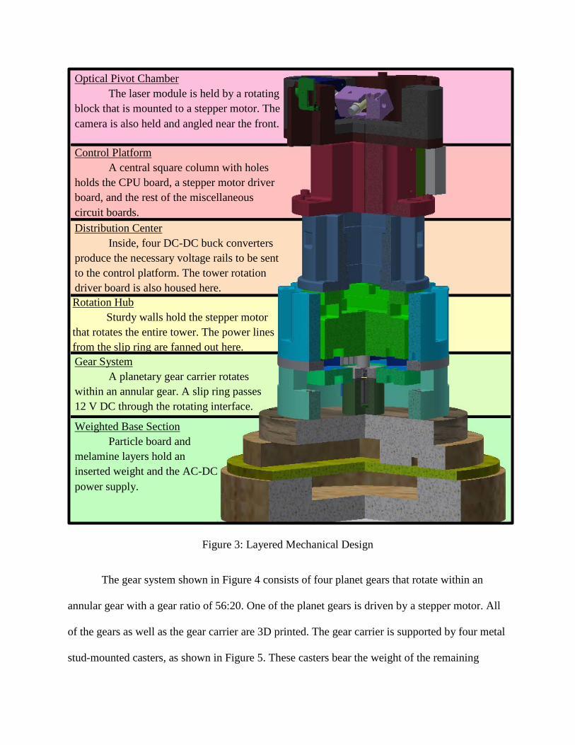
Figure 3: Layered Mechanical Design
The gear system shown in Figure 4 consists of four planet gears that rotate within an
annular gear with a gear ratio of 56:20. One of the planet gears is driven by a stepper motor. All
of the gears as well as the gear carrier are 3D printed. The gear carrier is supported by four metal
stud-mounted casters, as shown in Figure 5. These casters bear the weight of the remaining
Weighted Base Section Particle board and
melamine layers hold an inserted weight and the AC-DC power supply.
Optical Pivot Chamber The laser module is held by a rotating block that is mounted to a stepper motor. The camera is also held and angled near the front.
Control Platform A central square column with holes holds the CPU board, a stepper motor driver board, and the rest of the miscellaneous circuit boards. Distribution Center Inside, four DC-DC buck converters produce the necessary voltage rails to be sent to the control platform. The tower rotation driver board is also housed here. Rotation Hub Sturdy walls hold the stepper motor that rotates the entire tower. The power lines from the slip ring are fanned out here. Gear System A planetary gear carrier rotates within an annular gear. A slip ring passes 12 V DC through the rotating interface.

subsystems. Through the center of the gear
system, a slip ring provides an electrical
interface between the stationary power
supply and the rest of the system above as it
rotates.
The rotation hub, shown in Figure 6,
is bolted to the gear carrier and holds a
stepper motor in place over the drive gear. The
type of motor used was a standard bipolar
stepper motor with a step size of 0.9°.
The 3D printed distribution center and
control platform are bolted in position above
the rotation hub and do not perform any
important mechanical functions besides adding
height and supporting the electrical system. On
top of the control platform, the optical pivot
chamber positions a stepper motor sideways as
shown in Figure 7. The horizontal stepper
motor is connected to a lightweight 3D printed
block that holds a 532 nm laser module tightly.
The stepper motor operates in microstep
mode to offer high angular resolution for
the angling of the beam. A potentiometer is axially coupled to the laser mount to provide
Figure 4: Gear System. Gear carrier is colored blue.
Figure 6: Rotation Hub. The 3D printed extrusion holds the stepper motor (dark blue) above the
drive gear so it can rotate the tower.
Figure 5: Gear Carrier. The carrier is supported by metal casters.

positional feedback to the stepper motor driver. The potentiometer also limits the range of
motion, mechanically preventing the laser from being tilted upwards.
The camera pivot is a small 3D printed part that is fastened by a set screw and holds the
camera at a fixed angle. The camera’s pitch is fixed because of the open-loop nature of the
optical tracking system’s controls; if the camera pitch and altitude are both known, then two-
dimensional image locations found by the recognition algorithm can be linearly mapped to three-
dimensional, real-world coordinates.
Considering the mechanical system as a whole, it can be readily seen that all of
versatility, adaptability, and safety requirements are met or facilitated by the design. The
continuous rotation enabled by the gear system facilitates autonomous search in a full circle, the
hardware all fits within the constrained dimensions and also has room for an AC adapter, and it
can be easily seen that the system’s physical motion does not endanger any part of its
surroundings outside of its footprint. The mechanical design fully meets its requirements.
Figure 7: Optical Pivot Chamber
Bipolar Stepper Motor
Camera Pivot
Laser Mount

B. Electrical Hardware
The electrical hardware of the optical tracking system project serves four functions. The
first function is to support a computer system, the second function is to offer the computer
control over the motor and laser outputs, the third function is to provide input to the computer
system, and the fourth function is to distribute power. Schematics for the subsystems that
perform these functions are shown here along with a brief description of each subsystem’s key
features and components. The block diagram in Figure 8 shows an overview of the entire system.
The Raspberry PI 2 Model B (RPi2B) was selected for the computer system for a number
of reasons, chief among them being its ability to rapidly process images. This is because the
RPi2B has a quad core 900MHz processor and 1 GB of random access memory [1]. Mounted
Figure 8: Electrical System Overview

from the control platform, the
RPi2B uses its general purpose
input/output (GPIO) pins to connect
to various drivers and inputs while
a ribbon cable connects the
Raspberry Pi Camera [2]. Figure 9
shows the GPIO pinout for the
RPi2B and Figure 10 shows how
these pins are used in the optical
tracking system.
All of the pins in Figure 10
that are color coded as violet are
serial peripheral interface (SPI) pins
that conform to the SPI standard [4].
The SPI pins communicate with the
L6470 stepper motor driver board [5]
to give the RPi2B control of the laser
tilt position. This communication is
enhanced by the busy signal input
pin that allows motion
synchronization. The Motor Control
Bits and the Laser Control Bit are
sent to an op amp buffer array that converts logic levels. Because the state of these pins are
Figure 10: Pin Utilization of Optical Tracking System
Figure 9: Complete Raspberry Pi 2 GPIO Header [3]
sometimes unknown when the RPi2B begins its boot process, the Custom Driver Enable Bit is
able to activate and deactivate the op amp buffer array so that the laser and tower rotation are
disabled until system is in a known state. Finally, the Start Button Input Bit is wired to an
external push button that allows a user to start and stop the system for easy demonstration and
testing.
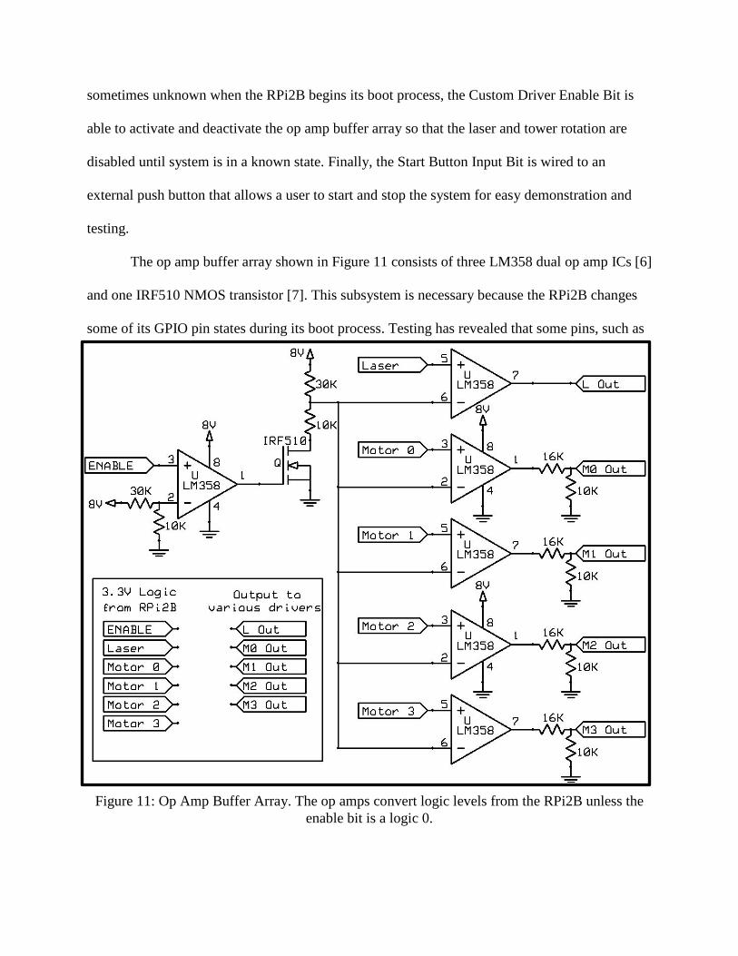
The op amp buffer array shown in Figure 11 consists of three LM358 dual op amp ICs [6]
and one IRF510 NMOS transistor [7]. This subsystem is necessary because the RPi2B changes
some of its GPIO pin states during its boot process. Testing has revealed that some pins, such as
Figure 11: Op Amp Buffer Array. The op amps convert logic levels from the RPi2B unless the enable bit is a logic 0.

pin 39, do not change state during the boot process and can be used to keep the output of the
system stable until the intended project code is ready to be executed.
The custom stepper motor driver depicted in Figure 12 is responsible for
controlling the tower rotation. This driver resides at the top of the distribution center and supplies
high current pulses to the bipolar stepper motor using two H-bridges made with IRF510 N-
channel MOSFETs and IRF9520 P-channel MOSFETs [8]. The gates of these high power
transistors labeled A1, A2, B1, and B2 in Figure 12 receive pulse trains that are generated by the
LPC1114 Arm Cortex-M0 microcontroller [9] and amplified by a pair of LM358 IC chips. The
LPC1114 receives instructions from the RPi2B via four binary signals passed through the op
Figure 12: Custom Stepper Motor Driver. The ARM Cortex M0, dual H-bridges, and 3V voltage regulator circuit are shown. The gate nodes A1, A2, B1, and B2 carry pulse trains.

amp buffer array. Interpretations of these commands are shown in Table 2. The 0000 command
causes the driver to release both H bridges, saving power and allowing the tower to coast. The
1000 command holds both H bridges in their current step, which causes the tower rotation to
brake. Every other command causes the tower to rotate to the right (clockwise) or to the left
(counterclockwise) at different speeds. The value Tstep indicates the interval of time between
motor steps. A sample set of pulse trains produced by the LPC1114 is shown in Figure 13. Each
step corresponds to a motor rotation of 0.9° and a tower rotation of 0.32°.
While the stepper motor in charge of
tower rotation is driven with a focus on speed
and torque, the stepper motor in the optical pivot chamber is driven for slow, careful angular
precision. Because of this, it is driven by a prefabricated board from SparkFun Electronics that
uses the L6470 driver integrated circuit. This board was selected because it can perform
microstepping, a sensitive, high power analog process that gradually phases between steps. The
microstepping greatly increases the resolution of the stepper motor from 0.9° per step up to
.00703° per microstep. In this project, the L6470 was configured to use a resolution of .0283° per
Table 2: Command Codes for Custom Stepper Motor Driver
M3 M2 M1 M0
Direction Tstep (ms) 0 0 0 0 Release 0 0 0 1 → 50.0 0 0 1 0 → 40.0 0 0 1 1 → 30.0 0 1 0 0 → 20.0 0 1 0 1 → 10.0 0 1 1 0 → 5.0 0 1 1 1 → 2.5 1 0 0 0 Brake 1 0 0 1 ← 50.0 1 0 1 0 ← 40.0 1 0 1 1 ← 30.0 1 1 0 0 ← 20.0 1 1 0 1 ← 10.0 1 1 1 0 ← 5.0 1 1 1 1 ← 2.5
Figure 13: Sample Step Signals. The name of each signal corresponds to the voltage nodes
on Figure 12 of the same name.
microstep, which is sufficient to move the laser impact location by 1 cm at the maximum
distance of 1 yard.
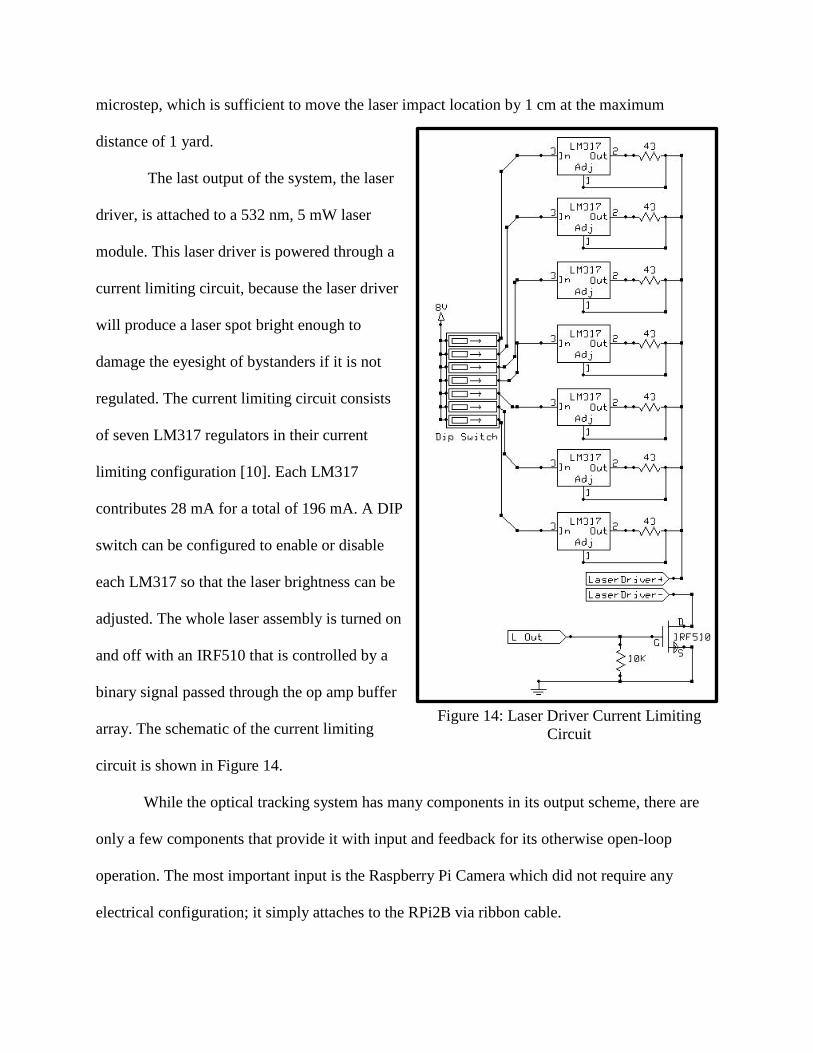
The last output of the system, the laser
driver, is attached to a 532 nm, 5 mW laser
module. This laser driver is powered through a
current limiting circuit, because the laser driver
will produce a laser spot bright enough to
damage the eyesight of bystanders if it is not
regulated. The current limiting circuit consists
of seven LM317 regulators in their current
limiting configuration [10]. Each LM317
contributes 28 mA for a total of 196 mA. A DIP
switch can be configured to enable or disable
each LM317 so that the laser brightness can be
adjusted. The whole laser assembly is turned on
and off with an IRF510 that is controlled by a
binary signal passed through the op amp buffer
array. The schematic of the current limiting
circuit is shown in Figure 14.
While the optical tracking system has many components in its output scheme, there are
only a few components that provide it with input and feedback for its otherwise open-loop
operation. The most important input is the Raspberry Pi Camera which did not require any
electrical configuration; it simply attaches to the RPi2B via ribbon cable.
Figure 14: Laser Driver Current Limiting Circuit

One somewhat valuable source of feedback is the potentiometer that is axially coupled to
the laser mount in the optical pivot chamber. This potentiometer is read by the L6470’s analog to
digital converter (ADC) because the RPi2B does not possess any ADC capabilities. The L6470’s
ADC has only five bits of resolution, but it can provide the optical tracking system a crude
starting position so that the laser’s angle is not completely unknown on startup. While this
feature was useful for debugging, it was not used in the final project.
The last part of the optical tracking system’s input is the start button, which consists of a
large push button connected to the base of the tower. The signal from the start button passes
through the slip ring and reaches the RPi2B’s GPIO, which allows the user to start and stop the
main program without having to touch the rotating part of the system.
The tilt sensor, as part of the safety requirements, was not implemented in the final
project due to time and budget constraints. Attempts were made to use inexpensive tilt switches,
as suggested in the project proposal, but these switches displayed unreliable characteristics that
defeated their purpose as a safety feature. If more time were allotted to the project, it would be
possible to connect a more expensive accelerometer to the RPi2B via SPI interface to alert the
optical tracking system if it is knocked over.
The last part of the electrical hardware of the optical tracking system is the power
distribution system. Figure 8 summarizes the distribution of power with the red arrows
representing the different voltage rails. This scheme will be elaborated upon and tabulated here.
To conform to one of the versatility requirements, the entire system is powered by an AC
power adapter salvaged from an old computer monitor. The adapter produces 12 V and is rated
for an average current of 6 A. This DC voltage rail is passed to the rest of the electrical system
through a slip ring that is rated for 10 A. On the rotating side of the slip ring, 12 V DC is fed into

four buck converters. Three of these are MP1584EN adjustable converters [11] which produce
the 5V for the RPi2B and 8V for the L6470 and laser driver. The fourth buck converter is the
DROK 12V to 7.5V Module which provides high power to the custom stepper motor driver.
These buck converters behave like step down transformers for DC voltages, trading voltage for a
current boost. This reduces the amount of current that is drawn from the power supply by
roughly a factor of 1.6. Table 3 shows the current load of each major electrical subsystem and
how the loads are reduced by the buck converters. As shown in Table 3, the entire electrical
system under maximum operating conditions can save as much as 19.8 W thanks to the buck
converters.
With the exception of the tilt sensor, the electrical hardware design was completely
implemented to equip the computer system with everything it needs to meet the project
requirements. The RPi2B has complete control over the tower rotation and laser module, and it
also can view its surroundings with its camera to perform optical tracking.
Table 3: Current Loading
System Operating Voltage Maximum Average Current
Converted Average Current
Raspberry PI 2 and Raspberry PI Camera
5 V 500 mA 208 mA
Custom Stepper Motor Driver
7.5 V 3.2 A 2 A
L6470 Stepper Motor Driver
8 V 274 mA 183.7 mA
Laser Driver 8 V 200 mA 133.3 mA
Total Current 4.174 A 2.525 A Maximum Power from 12V Supply 50.1 W 30.3 W

C. Software Design and Development
The software portion of the project design discussion consists of a brief overview of the
development environment followed by an explanation of the algorithm used in the finished
project. It is understood that countless libraries and interfaces developed by third parties were
used to support the development of this optical tracking project, so only the libraries most
deliberately selected for this project will be discussed and referenced. The libraries that provide
more platform-specific background functionality will be listed in Appendix B.
The Raspberry Pi 2 Model B runs an operating system called Raspian Wheezy, which a
distribution of Debian Linux optimized for the Raspberry Pi [12]. Running a general purpose
operating system allows comfortable native development through familiar interfaces and
programs. The project proposal suggested that the optical tracking system would be developed
through cross compilation, but native development was employed halfway through the project
schedule instead due to several unsolved networking and toolchain issues.
The project code was written in C++ and its compilation was assisted with CMake [13].
CMake allowed for easy customization and generation of make files, which made linking several
libraries easy and fast. The result of the compilation was an executable file that could be run via
shell script. The shell script would check the state of the start button as a background task and
start the executable if the button was pressed.
The most important library used in the development of the optical tracking system was
the OpenCV library, which supports matrix formatting, matrix operations, and useful computer
vision tools [14]. The WiringPi [15] and Raspicam [16] libraries were also instrumental in the
peripheral integration into the source code.
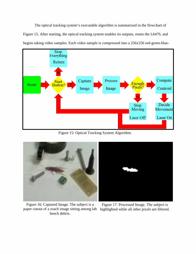
The optical tracking system’s executable algorithm is summarized in the flowchart of
Figure 15. After starting, the optical tracking system enables its outputs, resets the L6470, and
begins taking video samples. Each video sample is compressed into a 256x256 red-green-blue-
Figure 15: Optical Tracking System Algorithm.
Figure 16: Captured Image. The subject is a paper cutout of a roach image sitting among lab
bench debris. Figure 17: Processed Image. The subject is
highlighted while all other pixels are filtered.

alpha (RGBA) matrix and converted into a hue-saturation-value (HSV) matrix. Preset HSV
limits are then imposed on the resulting matrix, which produces a field of 0’s and 1’s, where 1’s
represent the pixels in the original image that met the preset HSV criteria. This field of binary
values is then morphologically dilated and eroded several times to eliminate visual noise and
solidify visual bodies. If an original image shown in Figure 16 is processed by the algorithm
described, the image in Figure 17 will result. The centroid of the white pixels in Figure 17 will
yield the pixel location that represents the center of the target object. This information will then
be used to determine which way the tower should rotate, how fast it should rotate, and which
angle to position the laser pivot. If not enough pixels in the processed image meet the criteria, the
tower will turn off its laser and wait until a more detectable target appears.
Even though this algorithm successfully finds and tracks objects, there are a few
versatility drawbacks inherent to its design. The first problem is that the only way to change the
HSV filter limits is to put the program in debug mode, manually tune the limits with a sample
target, and then save the tuned limits by recompiling the application. This means that for every
different type of object the user wishes to track, the program must be altered depending on the
color of the desired target.
Another drawback worthy of mention is that if there are two or more objects that meet the
filter criteria, then the centroid will return the average position of the two objects. This means
that if two targets of roughly the same size are in view, the optical tracking system will point its
laser on the ground between the two objects. This flaw can be overcome using a technique in
which each white pixel in the processed image is assigned a value according to the concentration
of neighboring white pixels. This technique was not implemented in the final build of the project
due to time constraints.

The only project requirement not met by the optical tracking system’s algorithm is that it
is not set to autonomously search for targets; it will merely follow any target that wanders into its
field of vision and stop moving if no targets are detected. It is safely considered trivial to make
the optical tracking system rotate as its default behavior instead of sitting idle, but the rotating
behavior was not implemented to create a more interesting and efficient demonstration. If no
target is detected, a user is able to manually rotate the tower and observe the behavior of the
Figure 18: Optical Tracking System Demonstration. The small purple toy is tagged by the optical tracking system’s green laser.

system. The stationary default behavior also reduces the power consumption and noisiness of the
project during demonstration.
Aside from the weaknesses previously discussed, the optical tracking system’s algorithm
successfully proves the optical tracking concept. The algorithm can be tuned and improved
considerably to produce more accurate optical tracking in the future.
IV. Test Results
The optical tracking system was successfully configured to point its laser at a paper
cutout of a roach picture, which minimally proved its ability to locate and track objects. To
further prove the optical tracking concept, a purple remote-controlled toy was used as the target.
The optical tracking system was configured to follow purple objects and was set on the ground.
As shown in Figure 18, the optical tracking system was able to point its laser at the toy, and it
was also able to quickly follow it as the toy was remotely driven around the room. The optical
tracking system could accurately strike the fast-moving target anywhere in a full 360° circle at a
distance between 1.3 feet and 4.5 feet from the center of the tower base. The demonstration was
very repeatable, and it was performed in a variety of environments, with only slightly tuning
with each new area. The optical tracking system project was definitely a success.
V. Project Cost
The cost of producing the optical tracking system is calculated in two ways to avoid
ambiguity. The first total, called the manufacturing cost, is the total price of all prefabricated
components that were actually used in the project, along with an estimate of milling and plastic
molding costs. The manufacturing cost is shown in Table 4 with asterisks next to items with

estimated costs. The second total, called the research cost, is the total amount actually spent from
the $400 budget allotted to the optical tracking system senior project. This distinction is made
because some components and software products that were purchased with the budget were not
used in the final project, although they might have been used in different design and
experimentation stages. The 3D printing and machining services used in the making of this
project were free of charge to the student, and are thus excluded from the research cost.
Table 4: Manufacturing Cost Table 5: Research Cost Item Cost Item Cost
Raspberry Pi 2 Model B $35.00 USB Connectors $9.99 Raspberry Pi Camera $25.00 Slip Rings $44.95 USB Connector $1.66 Express PCB Service $65.05 Start Button $4.00 Buck Converters $32.44 Slip Ring $15.00 VisualGDB License $54.50 SD Card $9.99 Stepper Motors $66.00 Buck Converters $12.28 L6470 Stepper Driver $34.50 Power Supply $7.32 Hardware Supplies $27.34 L6470 Stepper Driver $34.50 Power Supply $7.32 LPC1114 $1.95 Metal Casters $38.02 Stepper Motors $66.00 Tilt Sensor $1.50 Laser Module $14.50 Laser Module $14.50 Printed Circuit Boards $65.05 Nuts, Bolts, and Washers $20.00 Plastic $50.00 Particle Board $15.00 Metal Casters $19.01 Wires, Connectors $6.00 Total $405.26 Total $396.11
VI. Safety Evaluation and Consideration of Standards
Because the optical tracking system uses a laser, a power supply, and moving parts,
safety is an important part of the design. The two safety project requirements that were met
address the most important safety risks; the device is very difficult to knock over, and there is

very little risk of the laser being pointed at someone’s face. These project design aspects make
the project safe to demonstrate in most environments.
The wiring used in connecting the electrical components within the device’s rotating
enclosure do not perfectly adhere to the IEEE C2-2012 standard [17], although consideration was
given to its guidelines to reduce the chance of electrical malfunction and damage. The laser
pointer used in this project is a class-I laser, according to the IEC 60825-1:2007 standard [18] so
permanent eye injury should not be a risk.
VII. Conclusion
The optical tracking system project proved that computer vision can be used to find
specific objects in an environment and indicate their presence using a hardware response. The
project’s safety and versatility requirements were almost completely met and the adaptability
requirements were completely met. This shows that computer vision can be safely and reliably
employed to perform automated detection in a variety of situations. The accuracy and robustness
of the optical tracking system can be improved with further research and may unlock possibilities
in future robotics projects.
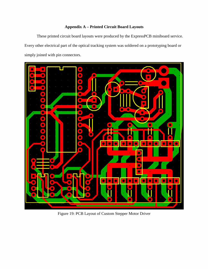
Appendix A – Printed Circuit Board Layouts
These printed circuit board layouts were produced by the ExpressPCB miniboard service.
Every other electrical part of the optical tracking system was soldered on a prototyping board or
simply joined with pin connectors.
Figure 19: PCB Layout of Custom Stepper Motor Driver
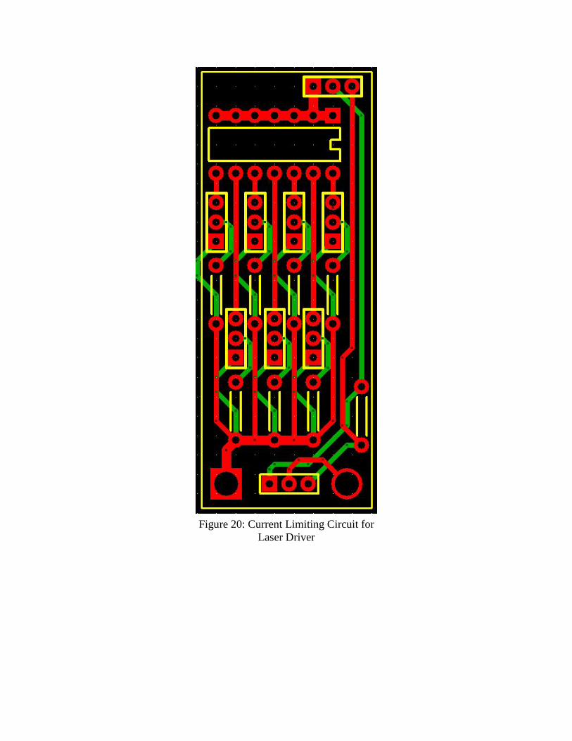
Figure 20: Current Limiting Circuit for Laser Driver
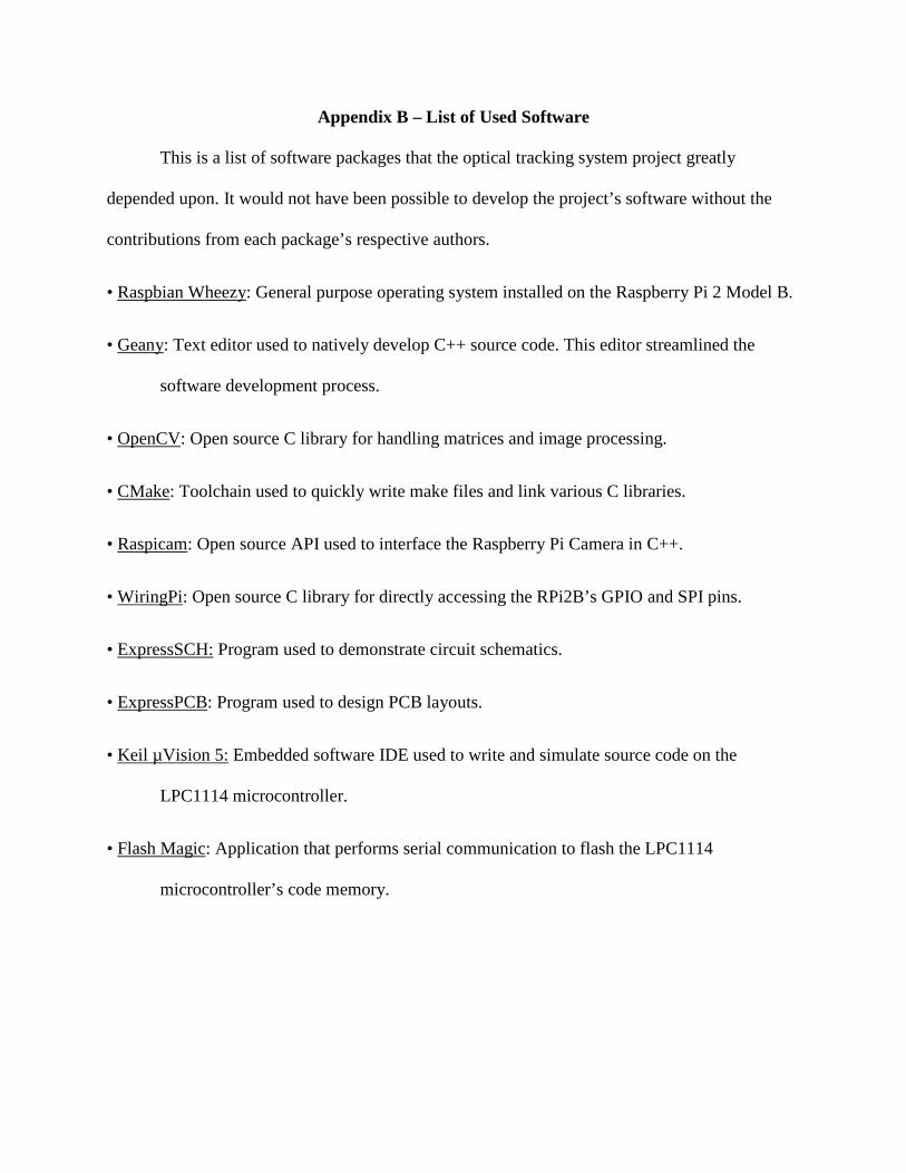
Appendix B – List of Used Software
This is a list of software packages that the optical tracking system project greatly
depended upon. It would not have been possible to develop the project’s software without the
contributions from each package’s respective authors.
• Raspbian Wheezy: General purpose operating system installed on the Raspberry Pi 2 Model B.
• Geany: Text editor used to natively develop C++ source code. This editor streamlined the
software development process.
• OpenCV: Open source C library for handling matrices and image processing.
• CMake: Toolchain used to quickly write make files and link various C libraries.
• Raspicam: Open source API used to interface the Raspberry Pi Camera in C++.
• WiringPi: Open source C library for directly accessing the RPi2B’s GPIO and SPI pins.
• ExpressSCH: Program used to demonstrate circuit schematics.
• ExpressPCB: Program used to design PCB layouts.
• Keil µVision 5: Embedded software IDE used to write and simulate source code on the
LPC1114 microcontroller.
• Flash Magic: Application that performs serial communication to flash the LPC1114
microcontroller’s code memory.

Appendix C – Custom Driver Code
This is the C code loaded onto the LPC1114 ARM Cortex M0 microcontroller. There are
two source files listed: Main.c, GPIO.c.
//Main.c //Daniel Vibbert //This is the main code that runs in the custom stepper motor driver. #include <MasterDefinitions.h> //Function Prototypes extern void GPIOsetup(void); extern void StepNext(void); extern void StepBack(void); extern void StepOff(void); void SpeedSelect(void); //Delay constants const int delay7 = 25 - 1; const int delay6 = 50 - 1; const int delay5 = 100 - 1; const int delay4 = 200 - 1; const int delay3 = 300 - 1; const int delay2 = 400 - 1; const int delay1 = 500 - 1; //Main Program int main() { GPIOsetup(); StepOff(); //SETUP TMR16B0 - 16 bit timers SYSAHBCLKCTRL |= bit7; //Enable clock for 16-bit timer 0 TMR16B0PR = 4799; //Prescale register. 1 tick = 0.1ms TMR16B0MR0 = delay1; //Match count -> generates interrupt TMR16B0MCR |= bit0 + bit1 + bit2; //Interrupt, reset, and stop on match0 //Enable interrupt requests __enable_irq(); //Repeat this loop forever while(1) { SpeedSelect(); //Use pins to select speed TMR16B0IR = 1; //Reset timer interrupt bit TMR16B0TC = 0; //Start counter at 0 TMR16B0TCR |= 1; //Enable TimerCounter to run while((TMR16B0IR & 0x1) == 0); //Wait until match } } //Method that reads the four binary signals from the op amp buffer array. void SpeedSelect()
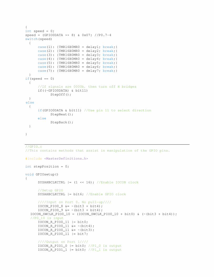
{ int speed = 0; speed = (GPIO0DATA >> 8) & 0x07; //P0.7-4 switch(speed) { case(1): {TMR16B0MR0 = delay1; break;} case(2): {TMR16B0MR0 = delay2; break;} case(3): {TMR16B0MR0 = delay3; break;} case(4): {TMR16B0MR0 = delay4; break;} case(5): {TMR16B0MR0 = delay5; break;} case(6): {TMR16B0MR0 = delay6; break;} case(7): {TMR16B0MR0 = delay7; break;} } if(speed == 0) { //If signals are 0000b, then turn off H bridges if((~GPIO0DATA) & bit11) StepOff(); } else { if(GPIO0DATA & bit11) //Use pin 11 to select direction StepNext(); else StepBack(); } } //GPIO.c //This contains methods that assist in manipulation of the GPIO pins. #include <MasterDefinitions.h> int stepPosition = 0; void GPIOsetup() { SYSAHBCLKCTRL |= (1 << 16); //Enable IOCON clock //Setup GPIO SYSAHBCLKCTRL |= bit6; //Enable GPIO clock ////Input on Port 0. No pull-up//// IOCON_PIO0_8 &= ~(bit3 + bit4); IOCON_PIO0_9 &= ~(bit3 + bit4);
IOCON_SWCLK_PIO0_10 = (IOCON_SWCLK_PIO0_10 + bit0) & (~(bit3 + bit4)); //P0_10 is input
IOCON_R_PIO0_11 |= bit0; IOCON_R_PIO0_11 &= ~(bit4); IOCON_R_PIO0_11 &= ~(bit3); IOCON_R_PIO0_11 |= bit7; ////Output on Port 1//// IOCON_R_PIO1_0 |= bit0; //P1_0 is output IOCON_R_PIO1_1 |= bit0; //P1_1 is output

IOCON_R_PIO1_2 |= bit0; //P1_2 is output IOCON_SWDIO_PIO1_3 |= bit0; //P1_3 is output GPIO1DIR |= bit4 + bit5 + bit6 + bit7; GPIO1DATA &= (~bit7); GPIO1DATA &= (~bit6); GPIO1DATA &= (~bit5); GPIO1DATA &= (~bit4); } void StepNext() { //0010 0x20 //1010 S 0xA0 //1000 0x80 //1001 T 0x90 //0001 0x10 //0101 E 0x50 //0100 0x40 //0110 P 0x60 stepPosition = (stepPosition + 1) % 4; switch(stepPosition) { case(0): {GPIO1DATA = 0x20; GPIO1DATA = 0xA0; break;} case(1): {GPIO1DATA = 0x80; GPIO1DATA = 0x90; break;} case(2): {GPIO1DATA = 0x10; GPIO1DATA = 0x50; break;} case(3): {GPIO1DATA = 0x40; GPIO1DATA = 0x60; break;} } } void StepBack() { stepPosition = (stepPosition + 3) % 4; switch(stepPosition) { case(0): {GPIO1DATA = 0xA0; break;} case(1): {GPIO1DATA = 0x90; break;} case(2): {GPIO1DATA = 0x50; break;} case(3): {GPIO1DATA = 0x60; break;} } } void StepOff() { GPIO1DATA = 0x00; }

Appendix D – Main Program Source Code
This is the C++ code developed natively on the Raspberry Pi 2 Model B. There are four
source files and two custom header files shown: DanielTower.cxx, Laser.cxx, Motor.cxx,
OpticalTracking.cxx, GPIO.h, and L6470.h.
//DanielTower.cxx //This is the main source code file for the optical tracking system project. //Imported Headers #include <stdio.h> #include <stdlib.h> #include <math.h> #include <ctime> #include <fstream> #include <raspicam/raspicam_cv.h> #include <wiringPi.h> #include <wiringPiSPI.h> #include <opencv2/core/core.hpp> #include <opencv2/imgproc/imgproc.hpp> #include <opencv2/highgui/highgui.hpp> #include <iostream> //Custom Headers #include <L6470.h> #include <GPIO.h> //Namespaces using namespace std; using namespace cv; //External Function Prototypes extern void Motor(int,int,int); extern void Laser(int); extern int LaserMountADC(); extern void LaserMountTilt(int); extern void LaserMountSetup(); extern void LaserMountStop(); extern void LaserMountGoHome(); extern void OpticalTracking(); //Function Prototypes void Setup(void); void Peripherals(int); void Cleanup(void); void Demo(void); void Project(void); //External Variables extern int laserTilt; //Local Variables int demoTimeout = 0; int demoTimeoutMax = 100; bool demoStarted = false; //MAIN// int main(int argc, char **argv) { Setup();
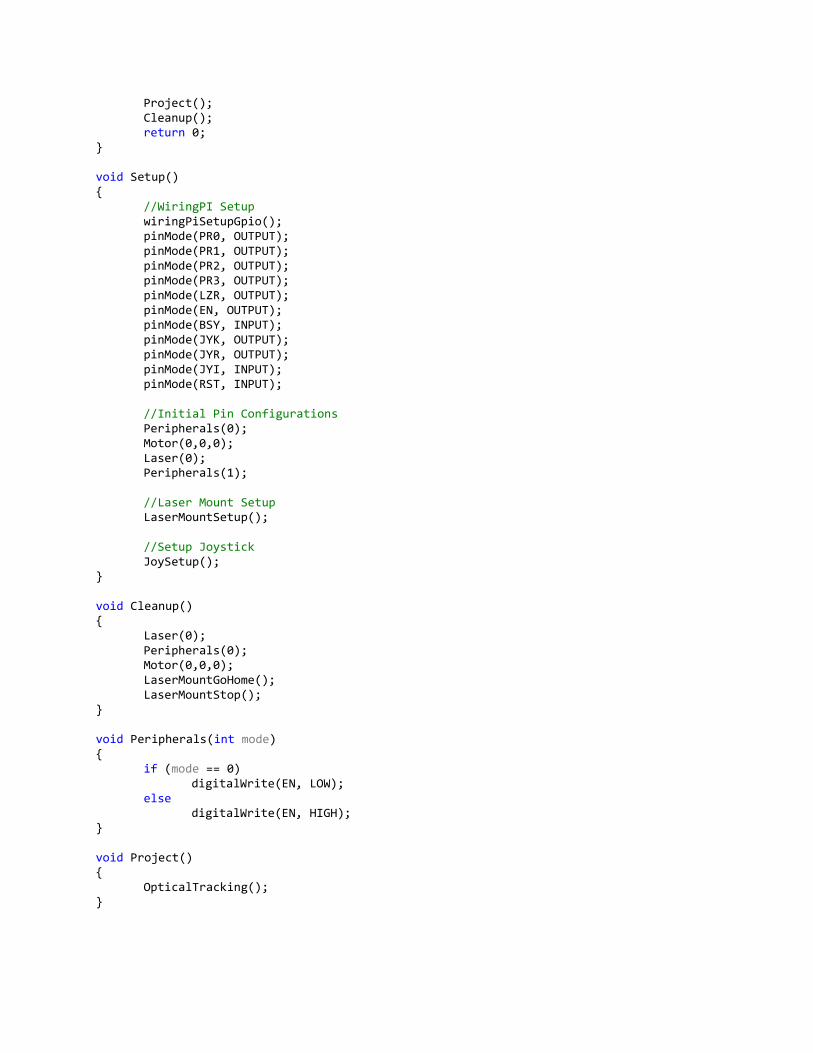
Project(); Cleanup(); return 0; } void Setup() { //WiringPI Setup wiringPiSetupGpio(); pinMode(PR0, OUTPUT); pinMode(PR1, OUTPUT); pinMode(PR2, OUTPUT); pinMode(PR3, OUTPUT); pinMode(LZR, OUTPUT); pinMode(EN, OUTPUT); pinMode(BSY, INPUT); pinMode(JYK, OUTPUT); pinMode(JYR, OUTPUT); pinMode(JYI, INPUT); pinMode(RST, INPUT); //Initial Pin Configurations Peripherals(0); Motor(0,0,0); Laser(0); Peripherals(1); //Laser Mount Setup LaserMountSetup(); //Setup Joystick JoySetup(); } void Cleanup() { Laser(0); Peripherals(0); Motor(0,0,0); LaserMountGoHome(); LaserMountStop(); } void Peripherals(int mode) { if (mode == 0) digitalWrite(EN, LOW); else digitalWrite(EN, HIGH); } void Project() { OpticalTracking(); }
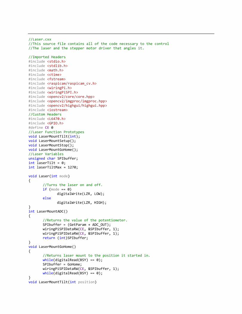
//Laser.cxx //This source file contains all of the code necessary to the control //The laser and the stepper motor driver that angles it. //Imported Headers #include <stdio.h> #include <stdlib.h> #include <math.h> #include <ctime> #include <fstream> #include <raspicam/raspicam_cv.h> #include <wiringPi.h> #include <wiringPiSPI.h> #include <opencv2/core/core.hpp> #include <opencv2/imgproc/imgproc.hpp> #include <opencv2/highgui/highgui.hpp> #include <iostream> //Custom Headers #include <L6470.h> #include <GPIO.h> #define CE 0 //Laser Function Prototypes void LaserMountTilt(int); void LaserMountSetup(); void LaserMountStop(); void LaserMountGoHome(); //Laser Variables unsigned char SPIbuffer; int laserTilt = 0; int laserTiltMax = 1270; void Laser(int mode) { //Turns the laser on and off. if (mode == 0) digitalWrite(LZR, LOW); else digitalWrite(LZR, HIGH); } int LaserMountADC() { //Returns the value of the potentiometer. SPIbuffer = (GetParam + ADC_OUT); wiringPiSPIDataRW(CE, &SPIbuffer, 1); wiringPiSPIDataRW(CE, &SPIbuffer, 1); return (int)SPIbuffer; } void LaserMountGoHome() { //Returns laser mount to the position it started in. while(digitalRead(BSY) == 0); SPIbuffer = GoHome; wiringPiSPIDataRW(CE, &SPIbuffer, 1); while(digitalRead(BSY) == 0); } void LaserMountTilt(int position)

{ //Moves the laser mount to the specified angle in microsteps unsigned char P1, P2, P3; P1 = 0; P2 = (unsigned char)((position & 0xFF00) >> 8); P3 = (unsigned char)((position & 0x0FF)); if(digitalRead(BSY) == 1) { SPIbuffer = GoTo; wiringPiSPIDataRW(CE, &SPIbuffer, 1); SPIbuffer = P1; wiringPiSPIDataRW(CE, &SPIbuffer, 1); SPIbuffer = P2; wiringPiSPIDataRW(CE, &SPIbuffer, 1); SPIbuffer = P3; wiringPiSPIDataRW(CE, &SPIbuffer, 1); } } void LaserMountStop() { //Forces the laser mount to stop moving. SPIbuffer = SoftStop; wiringPiSPIDataRW(CE, &SPIbuffer, 1); while(digitalRead(BSY) == 0); delay(100); SPIbuffer = HardHiZ; wiringPiSPIDataRW(CE, &SPIbuffer, 1); while(digitalRead(BSY) == 0); } void LaserMountSetup() { //SPI Setup wiringPiSPISetup(CE, 500000); delay(5); //Reset SPIbuffer = ResetDevice; wiringPiSPIDataRW(CE, &SPIbuffer, 1); while(digitalRead(BSY) == 0); //1/32 microstep = 0.9d / 32 = .028125d SPIbuffer = STEP_MODE; wiringPiSPIDataRW(CE, &SPIbuffer, 1); while(digitalRead(BSY) == 0); SPIbuffer = 5; wiringPiSPIDataRW(CE, &SPIbuffer, 1); while(digitalRead(BSY) == 0); SPIbuffer = ResetPos; wiringPiSPIDataRW(CE, &SPIbuffer, 1); while(digitalRead(BSY) == 0); }
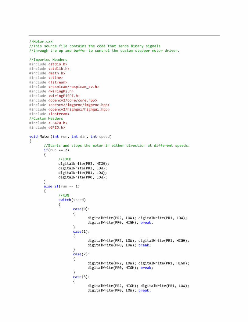
//Motor.cxx //This source file contains the code that sends binary signals //through the op amp buffer to control the custom stepper motor driver. //Imported Headers #include <stdio.h> #include <stdlib.h> #include <math.h> #include <ctime> #include <fstream> #include <raspicam/raspicam_cv.h> #include <wiringPi.h> #include <wiringPiSPI.h> #include <opencv2/core/core.hpp> #include <opencv2/imgproc/imgproc.hpp> #include <opencv2/highgui/highgui.hpp> #include <iostream> //Custom Headers #include <L6470.h> #include <GPIO.h> void Motor(int run, int dir, int speed) { //Starts and stops the motor in either direction at different speeds. if(run == 2) { //LOCK digitalWrite(PR3, HIGH); digitalWrite(PR2, LOW); digitalWrite(PR1, LOW); digitalWrite(PR0, LOW); } else if(run == 1) { //RUN switch(speed) { case(0): { digitalWrite(PR2, LOW); digitalWrite(PR1, LOW); digitalWrite(PR0, HIGH); break; } case(1): { digitalWrite(PR2, LOW); digitalWrite(PR1, HIGH); digitalWrite(PR0, LOW); break; } case(2): { digitalWrite(PR2, LOW); digitalWrite(PR1, HIGH); digitalWrite(PR0, HIGH); break; } case(3): { digitalWrite(PR2, HIGH); digitalWrite(PR1, LOW); digitalWrite(PR0, LOW); break;
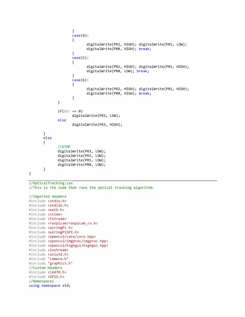
} case(4): { digitalWrite(PR2, HIGH); digitalWrite(PR1, LOW); digitalWrite(PR0, HIGH); break; } case(5): { digitalWrite(PR2, HIGH); digitalWrite(PR1, HIGH); digitalWrite(PR0, LOW); break; } case(6): { digitalWrite(PR2, HIGH); digitalWrite(PR1, HIGH); digitalWrite(PR0, HIGH); break; } } if(dir == 0) digitalWrite(PR3, LOW); else digitalWrite(PR3, HIGH); } else { //STOP digitalWrite(PR3, LOW); digitalWrite(PR2, LOW); digitalWrite(PR1, LOW); digitalWrite(PR0, LOW); } } //OpticalTracking.cxx //This is the code that runs the optical tracking algorithm. //Imported Headers #include <stdio.h> #include <stdlib.h> #include <math.h> #include <ctime> #include <fstream> #include <raspicam/raspicam_cv.h> #include <wiringPi.h> #include <wiringPiSPI.h> #include <opencv2/core/core.hpp> #include <opencv2/imgproc/imgproc.hpp> #include <opencv2/highgui/highgui.hpp> #include <iostream> #include <unistd.h> #include "camera.h" #include "graphics.h" //Custom Headers #include <L6470.h> #include <GPIO.h> //Namespaces using namespace std;

using namespace cv; //External Function Prototypes extern void Motor(int,int,int); extern void Laser(int); extern int LaserMountADC(); extern void LaserMountTilt(int); extern void LaserMountSetup(); extern void LaserMountStop(); extern void LaserMountGoHome(); extern int JoySetup(); extern int JoyDemo(); extern void JoyPoll(); //Function Prototypes void OpticalTracking(void); int CameraSetup(void); void CameraCapture(void); void CameraShow(void); void ThresholdFilter(Mat*,Mat*); int CentroidOfMatrix(Mat*,Point*); void DrawCrosshairs(Mat*, Point*); int TiltFromPixelY(int); int MotorCommandFromTargetX(int); void CreateControlPanel(void); //External Variables extern int laserTilt; extern int laserTiltMax; //Local Defintions #define MAIN_TEXTURE_WIDTH 256 #define MAIN_TEXTURE_HEIGHT 256 #define Left 0 #define Right 1 //Inner Variables char tmpbuff[MAIN_TEXTURE_WIDTH*MAIN_TEXTURE_HEIGHT*4]; CCamera* cam; GfxTexture texture; const void* frame_data; int frame_sz; //External Variables extern int laserTilt; extern int laserTiltMax; //Local Variables Mat Capture, Output, TCapture; Point Target; const bool debugAdjust = false; int finish = 0; //Custom HSV limits -- Currently tuned for magenta colored objects outdoors. int H1=165,H2=179,S1=5,S2=255,V1=84,V2=255; ////// void OpticalTracking() { //This is the optical tracking algorithm. CameraSetup(); //DEBUG -- Create control GUI if(debugAdjust) { CreateControlPanel(); namedWindow("LASER",CV_WINDOW_NORMAL);

cvCreateTrackbar("FINISH","LASER", &finish, 1); namedWindow( "DW1", CV_WINDOW_NORMAL ); } //ENDDEBUG waitKey(30); //While the start button is still pushed... while(finish == 0 && digitalRead(RST) == 0) { //Take a video frame... CameraCapture(); //And process it. Output = Capture.clone(); ThresholdFilter(&Output, &TCapture); //DEBUG -- DISPLAY FILTERED IMAGE if(debugAdjust) imshow("Filtered", TCapture); //ENDDEBUG //If there are enough matching pixels to compute a centroid... if(CentroidOfMatrix(&TCapture, &Target)) { //Turn on the laser... Laser(1); //Move the laser mount... laserTilt = TiltFromPixelY(Target.y); LaserMountTilt(laserTilt); //DEBUG -- Indicate centroid on output image DrawCrosshairs(&Output, &Target); //ENDDEBUG //And send binary signals the tower rotation driver. switch(MotorCommandFromTargetX(Target.x)) { case(0): {Motor(1,Left,6); break;}; case(1): {Motor(1,Left,5); break;}; case(2): {Motor(1,Left,4); break;}; case(3): {Motor(1,Left,3); break;}; case(4): {Motor(1,Left,2); break;}; case(5): {Motor(1,Left,1); break;}; case(6): {Motor(1,Left,0); break;}; case(7): {Motor(0,0,0); break;}; case(8): {Motor(1,Right,0); break;}; case(9): {Motor(1,Right,1); break;}; case(10):{Motor(1,Right,2); break;}; case(11):{Motor(1,Right,3); break;}; case(12):{Motor(1,Right,4); break;}; case(13):{Motor(1,Right,5); break;}; case(14):{Motor(1,Right,6); break;}; default: {Motor(0,0,0); break;}; } } //If there are not enough matching pixels to compute a centroid... else { //Turn off the laser and stop rotating. Laser(0);

Motor(0,0,0); } waitKey(2); //DEBUG -- SHOW OUTPUT if(debugAdjust == true) imshow( "DW1", Output); //ENDDEBUG } //After the loop ends, release the camera and return to DanielTower.cxx StopCamera(); } void ThresholdFilter(Mat* M, Mat* N) { //This processes the image M to produce a field of 0's and 1's in N. Mat Tmp; Tmp = (*M).clone(); cvtColor(Tmp, Tmp, COLOR_BGR2HSV); inRange(Tmp, Scalar(H1, S1, V1), Scalar(H2, S2, V2), Tmp); erode(Tmp, Tmp, getStructuringElement(MORPH_ELLIPSE, Size(3,3))); dilate(Tmp, Tmp, getStructuringElement(MORPH_ELLIPSE, Size(3,3))); erode(Tmp, Tmp, getStructuringElement(MORPH_ELLIPSE, Size(3,3))); dilate(Tmp, Tmp, getStructuringElement(MORPH_ELLIPSE, Size(3,3))); Tmp.copyTo(*N); } int CentroidOfMatrix(Mat* M, Point* centroid) { //Uses the 1st order moments method to find the centroid //of pixels that match the HSV constraints. //Returns 1 if successful. *centroid and *outputMatrix are outputs. Moments m0 = moments(*M); double dM01 = m0.m01; double dM10 = m0.m10; double dArea = m0.m00; if(dArea > 200) { int targetX = dM10 / dArea; int targetY = dM01 / dArea; (*centroid).x = targetX; (*centroid).y = targetY; return 1; } else return 0; } ////// int CameraSetup() { InitGraphics(); //This is not my function. This is from picamdemo //StartCamera is also from picamdemo cam = StartCamera(MAIN_TEXTURE_WIDTH, MAIN_TEXTURE_HEIGHT, 30,4,true); Capture.create(MAIN_TEXTURE_WIDTH, MAIN_TEXTURE_HEIGHT, CV_8UC4); TCapture.create(MAIN_TEXTURE_WIDTH, MAIN_TEXTURE_HEIGHT, CV_8UC4); }
void CameraCapture() { //This takes a frame from the video stream and converts it to OpenCV format. if(cam->BeginReadFrame(0,frame_data,frame_sz)) { cam->EndReadFrame(0); Capture.data = (uchar*)frame_data; cvtColor(Capture, Capture, COLOR_RGBA2BGRA); flip(Capture, Capture, 0); } } void DrawCrosshairs(Mat* M,Point* P) { //Draws crosshairs on the matrix M at the specified point P. int X = (*P).x; int Y = (*P).y; line((*M), Point(X, Y-15), Point(X, Y+15), Scalar(255,0,0), 4 ); line((*M), Point(X-15, Y), Point(X+15, Y), Scalar(255,0,0), 4 ); } void CreateControlPanel() { //In debug mode, this creates a control GUI for tuning the filter values. namedWindow("Control", CV_WINDOW_NORMAL); cvCreateTrackbar("H1","Control",&H1,179); cvCreateTrackbar("H2","Control",&H2,179); cvCreateTrackbar("S1","Control",&S1,255); cvCreateTrackbar("S2","Control",&S2,255); cvCreateTrackbar("V1","Control",&V1,255); cvCreateTrackbar("V2","Control",&V2,255); namedWindow( "Filtered", CV_WINDOW_NORMAL ); } int MotorCommandFromTargetX(int input) { //Determines how fast and in what direction the tower should rotate, //given the horizional pixel position of the target. int T[15] = {-100, -60, -50, -40, -30, -20, -10, 0, 10, 20, 30, 40, 50, 60, 100}; double DX; int a, b, c; DX = (double)input - ((double)MAIN_TEXTURE_HEIGHT / 2); //Select X a = MAIN_TEXTURE_WIDTH / 2; c = 3; for(int i = 0; i < 15; i++) { b = abs(T[14 - i] - DX); if(b < a) { a = b; c = i; } } return c;

} int TiltFromPixelY(int input) { //Returns the value to be sent to the LaserTilt method //input is the vertical pixel position of the target. double Y = (double)input; double Z = (double)laserTiltMax; double I = (double)MAIN_TEXTURE_HEIGHT; double YO = ((I - Y) / I) * Z; if(YO > Z || YO < 0) return 0; else return (int)YO; }
//GPIO.h #define PR0 5 #define PR1 6 #define PR2 13 #define PR3 19 #define LZR 26 #define EN 21 #define BSY 27 #define JYK 4 #define JYR 3 #define JYI 2 #define RST 17
//L6470.h //Laser Pitch Stepper Driver Registers #define ABS_POS 1 #define EL_POS 1 #define MARK 3 #define SPEED 4 #define ACC 5 #define DEC 6 #define MAX_SPEED 7 #define MIN_SPEED 8 #define FS_SPD 15 #define KVAL_HOLD 9 #define KVAL_RUN 10 #define KVAL_ACC 11 #define KVAL_DEC 12 #define INT_SPED 13 #define ST_SLP 14 #define FN_SLP_ACC 15 #define FN_SLP_DEC 16 #define K_THERM 17 #define ADC_OUT 18 #define OCD_TH 19 #define STALL_TH 20 #define STEP_MODE 22 #define ALARM_EN 23 #define CONFIG 24

#define STATUS 25 //SPI command macros #define GetParam 32 #define MoveForward 64 #define MoveBackward 65 #define GoTo 96 #define GoHome 112 #define GoMark 120 #define SetHome 216 #define ResetDevice 192 #define ResetPos 0xD8 #define SoftStop 176 #define HardStop 184 #define SoftHiZ 160 #define HardHiZ 168 #define GetStatus 208

References
[1] "Raspberry pi 2 model B," Raspberry Pi. [Online]. Available:
https://www.raspberrypi.org/products/raspberry-pi-2-model-b/. Accessed: Apr. 26, 2016.
[2] "Camera module," Raspberry Pi. [Online]. Available:
https://www.raspberrypi.org/products/camera-module/. Accessed: Apr. 26, 2016.
[3] P. F. plc, "Raspberry pi 3 model B GPIO 40 pin block Pinout, in raspberry pi 3 documents |
element14 community," Google+. [Online]. Available:
https://www.element14.com/community/docs/DOC-73950/l/raspberry-pi-3-model-b-gpio-
40-pin-block-pinout. Accessed: Apr. 26, 2016.
[4] "TN0897 technical note ST SPI protocol," 2013. [Online]. Available:
http://www2.st.com/content/ccc/resource/technical/document/technical_note/58/17/ad/50/f
a/c9/48/07/DM00054618.pdf/files/DM00054618.pdf/jcr:content/translations/en.DM000546
18.pdf. Accessed: Apr. 26, 2016.
[5] "SparkFun AutoDriver - Stepper Motor Driver," in www.sparkfun.com, 2015. [Online].
Available: https://www.sparkfun.com/products/11611. Accessed: Apr. 26, 2016.
[6] "LM158 LMx58-N low-power, dual-operational amplifiers," Texas Instruments, 2000.
[Online]. Available: http://www.ti.com/lit/ds/symlink/lm158-n.pdf. Accessed: Apr. 26,
2016.
[7] "IRF510," International Rectifier. [Online]. Available: http://www.irf.com/product-
info/datasheets/data/irf510.pdf. Accessed: Apr. 26, 2016.
[8] "IRF9520," Vishay Siliconix. [Online]. Available:
http://www.vishay.com/docs/91074/91074.pdf. Accessed: Apr. 26, 2016.
[9] NXP Semiconductors, "LPC1110/11/12/13/14/15 32-bit ARM cortex-m0 microcontroller; up
to 64 kB flash and 8 kB SRAM," 2014. [Online]. Available:
http://www.nxp.com/documents/data_sheet/LPC111X.pdf. Accessed: Apr. 26, 2016.
[10] "LM317 3-Terminal adjustable regulator 1 features 3 description," Texas Instruments, 1997.
[Online]. Available: http://www.ti.com/lit/ds/symlink/lm317.pdf. Accessed: Apr. 26, 2016.
[11] MPS, "MP1584 3A, 1.5MHz, 28V step-down converter MPS CONFIDENTIAL AND
PROPRIETARY INFORMATION – INTERNAL USE ONLY the future of analog IC
technology DESCRIPTION," 2009. [Online]. Available:
http://www.haoyuelectronics.com/Attachment/MP1584/MP1584.pdf. Accessed: Apr. 26,
2016.
[12] "FrontPage," in Raspian. [Online]. Available: https://www.raspbian.org/. Accessed: Apr.
26, 2016.
[13] "Build, test and package your software with CMake," in cmake.org. [Online]. Available:
https://cmake.org/. Accessed: Apr. 26, 2016.
[14] "OpenCV," 2015. [Online]. Available: http://opencv.org/. Accessed: Apr. 26, 2016.
[15] "Wiring Pi," 2016. [Online]. Available: http://wiringpi.com/. Accessed: Apr. 26, 2016.
[16] "RaspiCam: C++ API for using raspberry camera with/without OpenCv," 2015. [Online].
Available: http://www.uco.es/investiga/grupos/ava/node/40. Accessed: Apr. 26, 2016.
[17] ‘C2-2012-2012 National Electrical Safety Code (NESC)’ [Online].
Available:http://standards.ieee.org/findstds/standard/C2-2012.html [Accessed 07-Dec-
2015].

[18] ‘IEC 60825-1:2007’ [Online]. Available: https://webstore.iec.ch/publication/17996
[Accessed 07-Dec-2015].