thermal and optical master-slave tracking system€¦ · thermal and optical master-slave tracking...
TRANSCRIPT

Thermal and Optical
Master-Slave Tracking System
User Manual
UD06890B
User Manual
COPYRIGHT © 2017 Hangzhou Hikvision Digital Technology Co., Ltd.
ALL RIGHTS RESERVED.
Any and all information, including, among others, wordings, pictures, graphs are the properties
of Hangzhou Hikvision Digital Technology Co., Ltd. or its subsidiaries (hereinafter referred to be
“Hikvision”). This user manual (hereinafter referred to be “the Manual”) cannot be reproduced,
changed, translated, or distributed, partially or wholly, by any means, without the prior written
permission of Hikvision. Unless otherwise stipulated, Hikvision does not make any warranties,
guarantees or representations, express or implied, regarding to the Manual.
About this Manual
This Manual is applicable to Thermal and Optical Master-Slave Tracking System.
The Manual includes instructions for using and managing the product. Pictures, charts, images
and all other information hereinafter are for description and explanation only. The information
contained in the Manual is subject to change, without notice, due to firmware updates or other
reasons. Please find the latest version in the company website
(http://overseas.hikvision.com/en/).
Please use this user manual under the guidance of professionals.
Trademarks Acknowledgement
and other Hikvision’s trademarks and logos are the properties of Hikvision in
various jurisdictions. Other trademarks and logos mentioned below are the properties of their
respective owners.
Legal Disclaimer
TO THE MAXIMUM EXTENT PERMITTED BY APPLICABLE LAW, THE PRODUCT DESCRIBED,
WITH ITS HARDWARE, SOFTWARE AND FIRMWARE, IS PROVIDED “AS IS”, WITH ALL FAULTS
AND ERRORS, AND HIKVISION MAKES NO WARRANTIES, EXPRESS OR IMPLIED, INCLUDING
WITHOUT LIMITATION, MERCHANTABILITY, SATISFACTORY QUALITY, FITNESS FOR A
PARTICULAR PURPOSE, AND NON-INFRINGEMENT OF THIRD PARTY. IN NO EVENT WILL
HIKVISION, ITS DIRECTORS, OFFICERS, EMPLOYEES, OR AGENTS BE LIABLE TO YOU FOR
ANY SPECIAL, CONSEQUENTIAL, INCIDENTAL, OR INDIRECT DAMAGES, INCLUDING, AMONG
OTHERS, DAMAGES FOR LOSS OF BUSINESS PROFITS, BUSINESS INTERRUPTION, OR LOSS
OF DATA OR DOCUMENTATION, IN CONNECTION WITH THE USE OF THIS PRODUCT, EVEN IF
HIKVISION HAS BEEN ADVISED OF THE POSSIBILITY OF SUCH DAMAGES.
REGARDING TO THE PRODUCT WITH INTERNET ACCESS, THE USE OF PRODUCT SHALL BE
WHOLLY AT YOUR OWN RISKS. HIKVISION SHALL NOT TAKE ANY RESPONSIBILITES FOR
ABNORMAL OPERATION, PRIVACY LEAKAGE OR OTHER DAMAGES RESULTING FROM CYBER
ATTACK, HACKER ATTACK, VIRUS INSPECTION, OR OTHER INTERNET SECURITY RISKS;
HOWEVER, HIKVISION WILL PROVIDE TIMELY TECHNICAL SUPPORT IF REQUIRED.

SURVEILLANCE LAWS VARY BY JURISDICTION. PLEASE CHECK ALL RELEVANT LAWS IN
YOUR JURISDICTION BEFORE USING THIS PRODUCT IN ORDER TO ENSURE THAT YOUR USE
CONFORMS THE APPLICABLE LAW. HIKVISION SHALL NOT BE LIABLE IN THE EVENT THAT
THIS PRODUCT IS USED WITH ILLEGITIMATE PURPOSES.
IN THE EVENT OF ANY CONFLICTS BETWEEN THIS MANUAL AND THE APPLICABLE LAW,
THE LATER PREVAILS.
Regulatory Information
FCC Information
Please take attention that changes or modification not expressly approved by the party responsible for
compliance could void the user’s authority to operate the equipment.
FCC compliance: This equipment has been tested and found to comply with the limits for a Class A
digital device, pursuant to part 15 of the FCC Rules. These limits are designed to provide reasonable
protection against harmful interference when the equipment is operated in a commercial environment.
This equipment generates, uses, and can radiate radio frequency energy and, if not installed and used in
accordance with the instruction manual, may cause harmful interference to radio communications.
Operation of this equipment in a residential area is likely to cause harmful interference in which case the
user will be required to correct the interference at his own expense.
FCC Conditions
This device complies with part 15 of the FCC Rules. Operation is subject to the following two conditions:
1. This device may not cause harmful interference.
2. This device must accept any interference received, including interference that may cause undesired
operation.
EU Conformity Statement
This product and - if applicable - the supplied accessories too are marked with "CE" and
comply therefore with the applicable harmonized European standards listed under the
Low Voltage Directive 2006/95/EC, the EMC Directive 2014/30/EU, the RoHS Directive
2011/65/EU.
2012/19/EU (WEEE directive): Products marked with this symbol cannot be disposed of
as unsorted municipal waste in the European Union. For proper recycling, return this
product to your local supplier upon the purchase of equivalent new equipment, or
dispose of it at designated collection points. For more information see:
www.recyclethis.info.
2006/66/EC (battery directive): This product contains a battery that cannot be disposed
of as unsorted municipal waste in the European Union. See the product documentation
for specific battery information. The battery is marked with this symbol, which may
include lettering to indicate cadmium (Cd), lead (Pb), or mercury (Hg). For proper
recycling, return the battery to your supplier or to a designated collection point. For more information see:
www.recyclethis.info.
Industry Canada ICES-003 Compliance
This device meets the CAN ICES-3 (A)/NMB-3(A) standards requirements.
Safety Instruction
These instructions are intended to ensure that the user can use the product correctly to avoid danger or
property loss.
The precaution measure is divided into ‘Warnings’ and ‘Cautions’:
Warnings: Serious injury or death may be caused if any of these warnings are neglected.
Cautions: Injury or equipment damage may be caused if any of these cautions are neglected.
Warnings Follow these safeguards to prevent
serious injury or death.
Cautions Follow these precautions to prevent
potential injury or material damage.
Warnings
The device should be used in compliance with local laws and electrical safety regulations. Refer to
the appropriate documentation for detailed information.
The input voltage should conform to IEC60950-1 standard: SELV (Safety Extra Low Voltage) and the
Limited Power Source (24 VAC/12 VDC). Refer to the appropriate documentation for detailed
information.
DO NOT connect multiple devices to one power adapter, to avoid over-heating or fire hazards
caused by overload.
Make sure the plug is properly connected to the power socket.
If smoke, odor, or noise arises from the device, immediately turn off the power, unplug the power
cable, and contact the service center.
The installer and user are responsible for password and security configuration and its settings.
Both internal and external grounds should be connected properly. (The cross section area of the
grounding wire must be no less than 4 mm2, and no less than that of the phase connector).
Cautions
Do not drop the device or subject it to physical shock.
Wipe the device gently with a clean cloth and a small quantity of ethanol, if necessary.
Do not aim the lens at the sun or any other bright light.
When any laser equipment is in use, make sure that the device lens is not exposed to the laser
beam, or it may burn out.
Do not expose the device to high electromagnetic radiation or extremely hot, cold, dusty, or damp
environments.
Place the device in a dry and well-ventilated environment.
Keep non-waterproof devices away from liquids.
Keep the device in original or similar packaging while transporting it.
A few device components (e.g., electrolytic capacitor) require regular replacement. The average
lifespan varies, so periodic checking is recommended. Contact your dealer for details.
Improper use or replacement of the battery may result in explosion hazard. Replace with the same
or equivalent type only. Dispose of used batteries in conformance with the instructions provided by
the battery manufacturer.
Never attempt to disassemble the device.
0504001070705
Table of Contents
Chapter 1 Overview ...................................................................................................................... 1
1.1 Overview ..................................................................................................................................................... 1 1.2 System Requirement ................................................................................................................................. 1 1.3 Functions .................................................................................................................................................... 2
Chapter 2 Appearance Description ............................................................................................. 4
2.1 Type I Master-slave System Appearance ............................................................................................... 4 2.2 Type II Master-slave System Appearance .............................................................................................. 5 2.3 Cable Wiring ............................................................................................................................................... 6
2.3.1 Speed Dome Cables ........................................................................................................................... 6 2.3.2 Bullet Camera Cables ......................................................................................................................... 6
Chapter 3 Installation .................................................................................................................. 6
3.1 Pre-Installation .......................................................................................................................................... 6 3.1.1 Wide Range Coverage ........................................................................................................................ 7 3.1.2 Memory Card Installation .................................................................................................................. 8
3.2 Bracket Installation .................................................................................................................................... 9 3.2.3 Type I Master-slave System Bracket Installation.......................................................................... 10 3.2.1 Type II Master-slave System Bracket Installation......................................................................... 11
3.3 PT joint Installation .................................................................................................................................. 12 3.4 Master-slave Tracking System Installation .......................................................................................... 13
3.4.2 Type I Master-slave System Bracket Installation.......................................................................... 13 3.4.3 Type II Master-slave System Bracket Installation......................................................................... 16
3.5 3-Axis Adjustment ................................................................................................................................... 19
Chapter 4 Network Connection ................................................................................................. 21
4.1 Setting the Camera over the LAN .......................................................................................................... 21 4.1.1 Wiring over the LAN .......................................................................................................................... 21 4.1.2 Activating the System ...................................................................................................................... 21
4.2 Setting the Network Camera over the WAN .......................................................................................... 26 4.2.3 Static IP Connection ......................................................................................................................... 26 4.2.4 Dynamic IP Connection ................................................................................................................... 27
Chapter 5 System Settings ....................................................................................................... 30
5.1 Access to the System ............................................................................................................................. 30 5.1.1 Adding Devices ................................................................................................................................. 30 5.1.2 Live View ............................................................................................................................................ 31
Chapter 6 Remote Configuration .............................................................................................. 32
6.1 Login the Speed Dome ............................................................................................................................ 32 6.2 Calibration ................................................................................................................................................ 34 6.3 Calibration Veryfication ........................................................................................................................... 36 6.4 Set Tracking Parameters ........................................................................................................................ 37 6.5 VCA Rule Configuration........................................................................................................................... 38
Chapter 7 Auto Master-slave Tracking .................................................................................... 40
Appendix ......................................................................................................................................... 41
Frequently Asked Questions (FAQ) ................................................................................................................... 41 Device Running Error ...................................................................................................................................... 41 Device Upgrading............................................................................................................................................ 41 Others............................................................................................................................................................... 41
Common Material Emissivity Reference ......................................................................................................... 42
Chapter 1 Overview
1.1 Overview
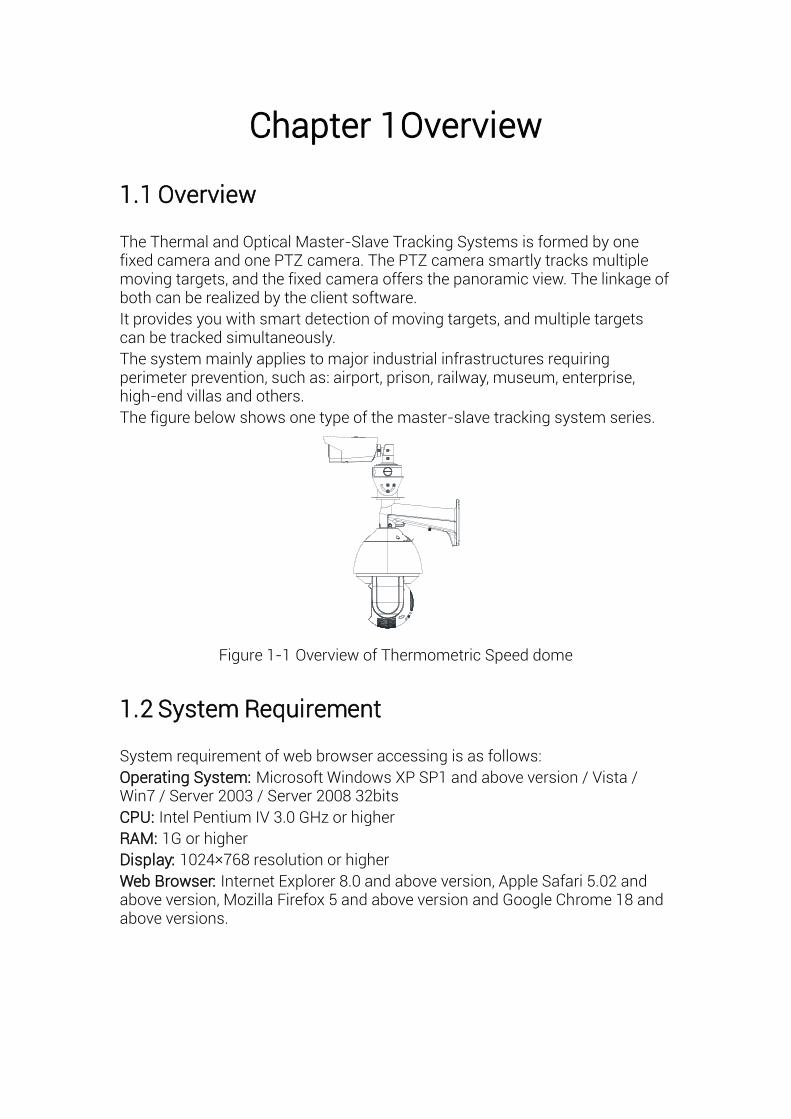
The Thermal and Optical Master-Slave Tracking Systems is formed by one fixed camera and one PTZ camera. The PTZ camera smartly tracks multiple moving targets, and the fixed camera offers the panoramic view. The linkage of both can be realized by the client software.
It provides you with smart detection of moving targets, and multiple targets can be tracked simultaneously.
The system mainly applies to major industrial infrastructures requiring perimeter prevention, such as: airport, prison, railway, museum, enterprise, high-end villas and others.
The figure below shows one type of the master-slave tracking system series.
Figure 1-1 Overview of Thermometric Speed dome
1.2 System Requirement
System requirement of web browser accessing is as follows:
Operating System: Microsoft Windows XP SP1 and above version / Vista / Win7 / Server 2003 / Server 2008 32bits
CPU: Intel Pentium IV 3.0 GHz or higher
RAM: 1G or higher
Display: 1024× 768 resolution or higher
Web Browser: Internet Explorer 8.0 and above version, Apple Safari 5.02 and above version, Mozilla Firefox 5 and above version and Google Chrome 18 and above versions.
1.3 Functions
Note: The functions vary depending on the models of speed dome.
Thermal View The system provides thermal view with the uncooled focal plane arrays.
PTZ Limits The speed dome can be programmed to move within the PTZ limits (left/right, up/down).
Scan Modes The speed dome provides 5 scan modes: auto scan, tilt scan, frame scan, random scan and panorama scan.
Presets A preset is a predefined image position. When the preset is called, the speed dome will automatically move to the defined position. The presets can be added, modified, deleted and called.
Label Display The on-screen label of the preset title, azimuth/elevation, zoom, time and speed dome name can be displayed on the monitor. The displays of time and speed dome name can be programmed.
Auto Flips In manual tracking mode, when a target object goes directly beneath the speed dome, the video will automatically flips 180 degrees in horizontal direction to maintain continuity of tracking. This function can also be realized by auto mirror image depending on different camera models.
Privacy Mask This function allows you to block or mask certain area of a scene, for preventing the personal privacy from recording or live viewing. A masked area will move with pan and tilt functions and automatically adjust in size as the lens zooms telephoto and wide.
3D Positioning In the client software, use the left key of mouse to click on the desired position in the video image and drag a rectangle area in the lower right direction, then the speed dome will move the position to the center and allow the rectangle area to zoom in. Use the left key of mouse to drag a rectangle area in the upper left direction to move the position to the center and allow the rectangle area to zoom out.
Proportional Pan/Tilt Proportional pan/tilt automatically reduces or increases the pan and tilt speeds according to the amount of zoom. At telephoto zoom settings, the pan and tilt speeds will be slower than at wide zoom settings. This keeps the image from moving too fast on the live view image when there is a large amount of zoom.
Auto Focus The auto focus enables the camera to focus automatically to maintain clear video images.
Day/Night Auto Switch The speed domes deliver color images during the day. And as light diminishes at night, the speed domes switch to night mode and deliver black and white images with high quality.
Slow Shutter In slow shutter mode, the shutter speed will automatically slow down in low illumination conditions to maintain clear video images by extending the exposure time. The feature can be enabled or disabled.
Backlight Compensation (BLC)
If you focus on an object against strong backlight, the object will be too dark to be seen clearly. The BLC (Backlight Compensation) function can compensate light to the object in the front to make it clear, but this causes the over-exposure of the background where the light is strong.
Wide Dynamic Range (WDR) The wide dynamic range (WDR) function helps the camera provide clear images even under back light circumstances. When there are both very bright and very dark areas simultaneously in the field of view, WDR balances the brightness level of the whole image and provide clear images with details.
White Balance (WB) White balance can remove the unrealistic color casts. White balance is the white rendition function of the camera to adjust the color temperature according to the environment automatically.
Patrol A patrol is a memorized series of pre-defined preset function. The scanning speed between two presets and the dwell time at the preset are programmable.
Pattern A pattern is a memorized series of pan, tilt, zoom, and preset functions. By default the focus and iris are in auto status during the pattern is being memorized.
Power Off Memory The speed dome supports the power off memory capability with the predefined resume time. It allows the speed dome to resume its previous position after power is restored.
Scheduled Task A scheduled task is a preconfigured action that can be performed automatically at a specific date and time. The programmable actions include: auto scan, random scan, patrol 1-8 ,pattern 1-4, preset 1-8,frame scan, panorama scan, tilt scan, day, night, reboot, PT adjust, Aux Output, etc.
Park Action This feature allows the speed dome to start a predefined action automatically after a period of inactivity.
3D Digital Noise Reduction Comparing with the general 2D digital noise reduction, the 3D digital noise reduction function processes the noise between two frames besides processing the noise in one frame. The noise will be much less and the video will be clearer.
Chapter 2 Appearance Description There are two kinds of Thermal and Optical Master-Slave Tracking Systems: Type I speed dome, and Type II speed dome. The appearance descriptions are shown below.
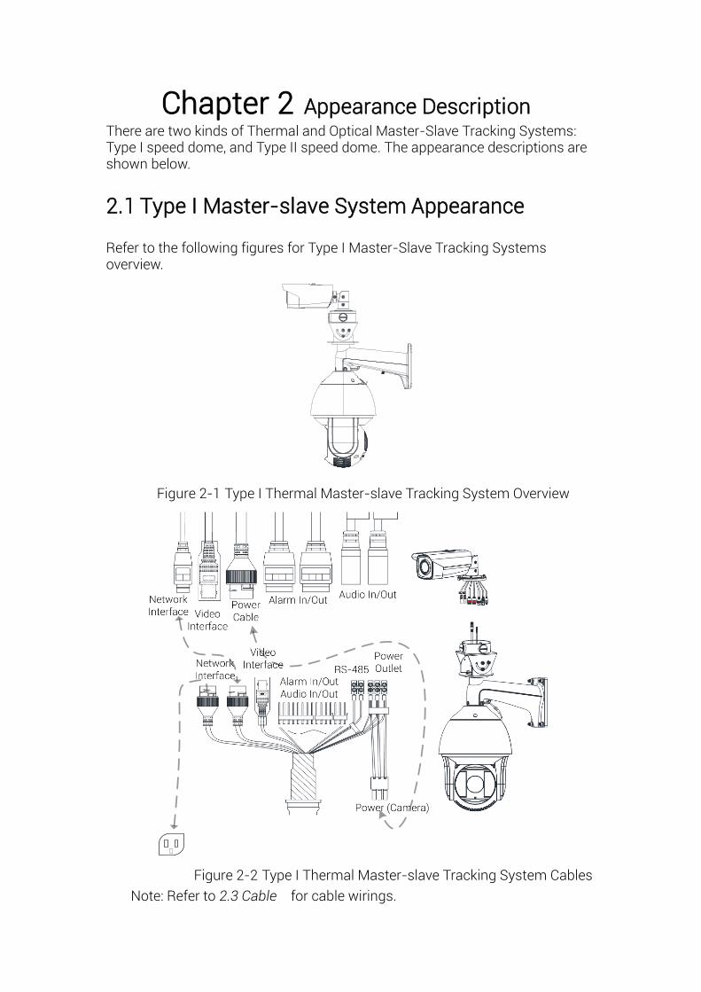
2.1 Type I Master-slave System Appearance
Refer to the following figures for Type I Master-Slave Tracking Systems overview.
Figure 2-1 Type I Thermal Master-slave Tracking System Overview
Figure 2-2 Type I Thermal Master-slave Tracking System Cables
Note: Refer to 2.3 Cable for cable wirings.
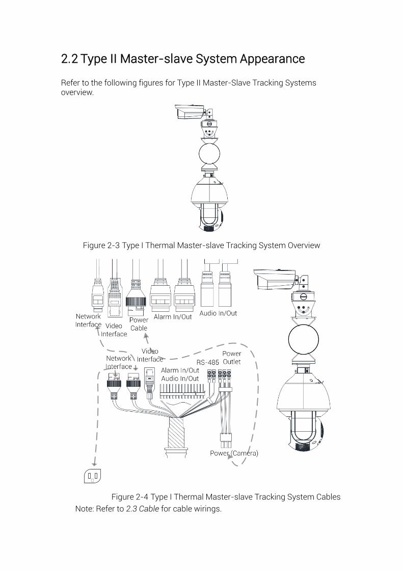
2.2 Type II Master-slave System Appearance
Refer to the following figures for Type II Master-Slave Tracking Systems overview.
Figure 2-3 Type I Thermal Master-slave Tracking System Overview
标题
Figure 2-4 Type I Thermal Master-slave Tracking System Cables
Note: Refer to 2.3 Cable for cable wirings.
2.3 Cable Wiring
2.3.1 Speed Dome Cables
1. The speed dome has two network interfaces:
Connect one network cable to the external internet, and connect the other
network cable to the bullet camera network interface.
2. The speed dome has two power interfaces:
Connect one power cable to the external power source, and connect the
other power cable to the bullet camera power interface.
2.3.2 Bullet Camera Cables
1. The bullet camera has two power types:
For bullet camera, both 24 V AC and 12 V DC are supported. To use 12V DC
power supply, you MUST connect the positive/negative terminals correctly.
For the master-slave tracking system, connect the bullet camera power
cable to the speed dome power output.
2. The speed dome has two power interfaces:
Connect one power cable to the external power source, and connect the
other power cable to the bullet camera power interface.
Chapter 3 Installation
3.1 Pre-Installation
● Make sure the device in the package is in good condition and all the assembly parts are included.
● The standard power supply is 24V AC, please make sure your power supply matches your camera.
● Make sure all the related equipment is power-off during the installation.
● Check the specification for the installation environment.
● Make sure that the wall is strong enough to withstand eight times the weight of the camera and the bracket.
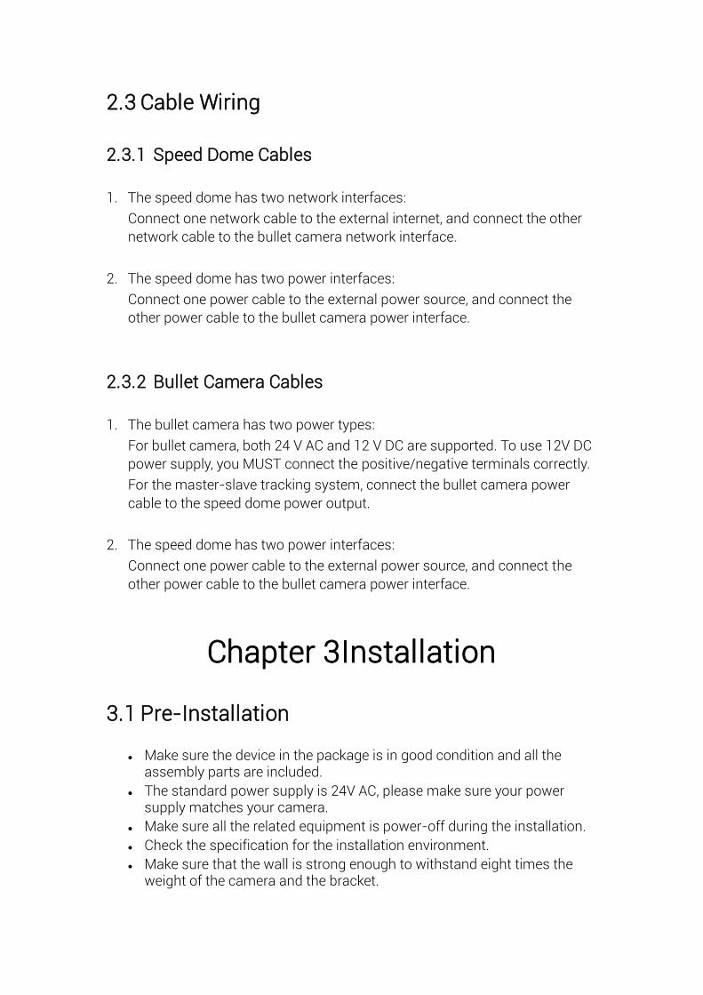
For the camera that supports IR, mind the following precautions to prevent IR reflection:
● Do NOT remove the protective film until you finish the installation. For any dust or grease on the cover, clean them with clean soft cloth and isopropyl alcohol.
● Make sure that there is no reflective surface too close to the camera lens. The IR light from the camera may reflect back into the lens causing reflection.
● Do NOT drag the camera with its waterproof cables, or the waterproof performance is affected.
Do NOT lift the camera by lifting the cables
Figure 3-1 Do NOT Lift by Cables
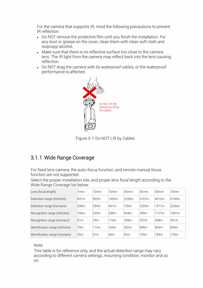
3.1.1 Wide Range Coverage
For fixed lens camera, the auto-focus function, and remote manual focus function are not supported.
Select the proper installation site, and proper lens focal length according to the Wide Range Coverage list below:
Lens (focal length) 7mm 10mm 15mm 25mm 35mm 50mm 75mm
Detection range (Vehicles) 631m 902m 1353m 2255m 3157m 4510m 6765m
Detection range (Humans) 206m 294m 441m 735m 1029m 1471m 2206m
Recognition range (Vehicles) 158m 225m 338m 564m 789m 1127m 1691m
Recognition range (Humans) 51m 74m 110m 184m 257m 368m 551m
Identification range (Vehicles) 79m 113m 169m 282m 395m 564m 846m
Identification range (Humans) 26m 37m 55m 92m 129m 184m 276m
Note: This table is for reference only, and the actual detection range may vary according to different camera settings, mounting condition, monitor and so on.
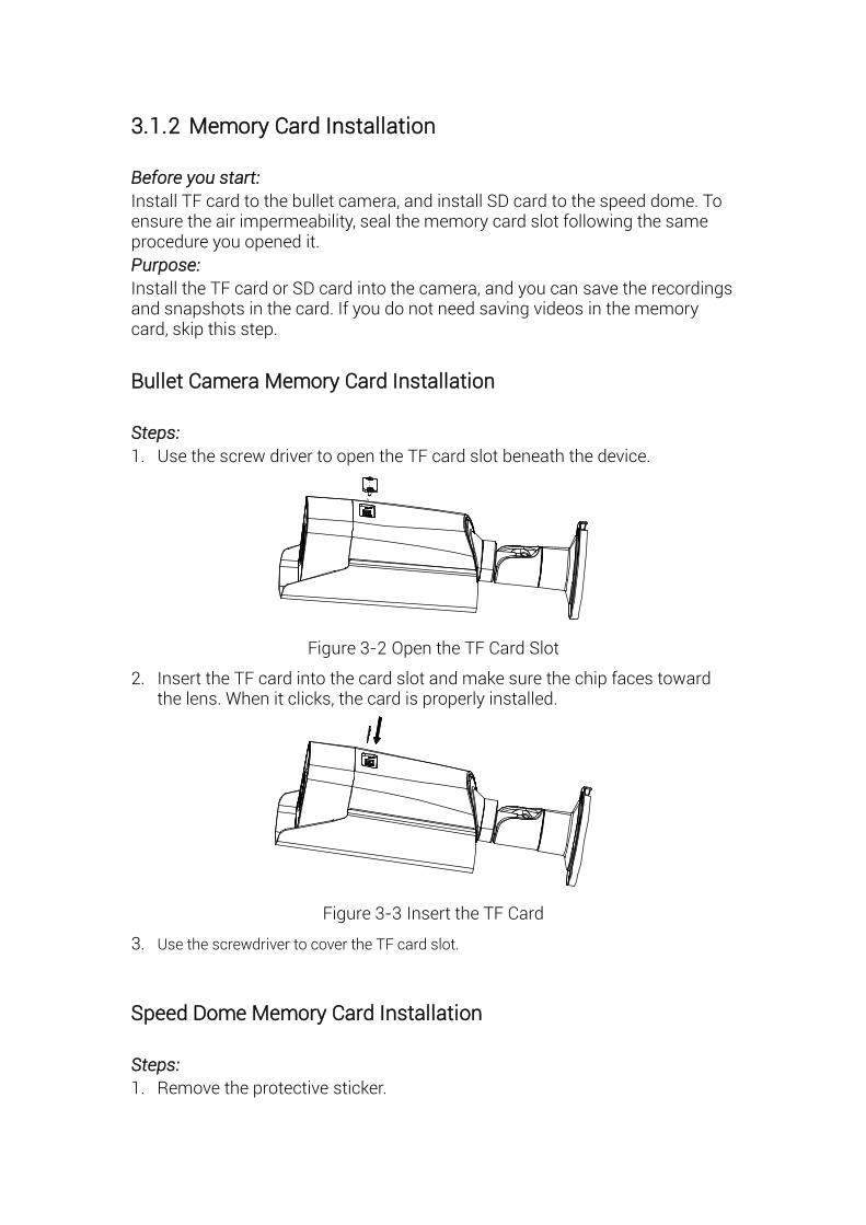
3.1.2 Memory Card Installation
Before you start:
Install TF card to the bullet camera, and install SD card to the speed dome. To ensure the air impermeability, seal the memory card slot following the same procedure you opened it.
Purpose:
Install the TF card or SD card into the camera, and you can save the recordings and snapshots in the card. If you do not need saving videos in the memory card, skip this step.
Bullet Camera Memory Card Installation
Steps:
1. Use the screw driver to open the TF card slot beneath the device.
Figure 3-2 Open the TF Card Slot
2. Insert the TF card into the card slot and make sure the chip faces toward the lens. When it clicks, the card is properly installed.
Figure 3-3 Insert the TF Card
3. Use the screwdriver to cover the TF card slot.
Speed Dome Memory Card Installation
Steps:
1. Remove the protective sticker.
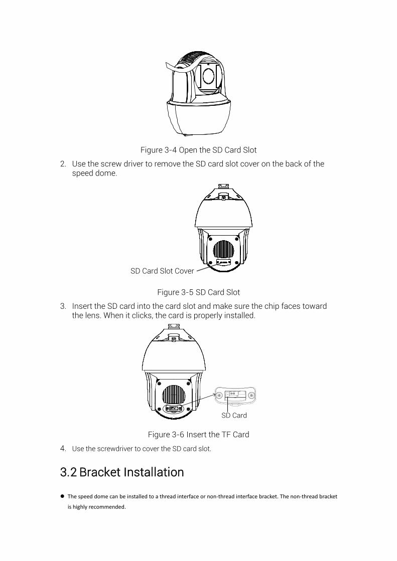
Figure 3-4 Open the SD Card Slot
2. Use the screw driver to remove the SD card slot cover on the back of the speed dome.
SD Card Slot Cover
Figure 3-5 SD Card Slot
3. Insert the SD card into the card slot and make sure the chip faces toward the lens. When it clicks, the card is properly installed.
SD Card
Figure 3-6 Insert the TF Card
4. Use the screwdriver to cover the SD card slot.
3.2 Bracket Installation
The speed dome can be installed to a thread interface or non-thread interface bracket. The non-thread bracket
is highly recommended.
When you select a thread bracket, please install the pendent adapter (supplied) between the bracket and speed
dome. Any mismatch problems shall be taken responsibility by the user.
The dimension of pendant adapter is G112 .
For cement wall, you need to use the expansion screw to fix the bracket.
For wooden wall, you can just use the self-tapping screw to fix the bracket.
Please make sure that the wall is strong enough to withstand at least 8 times the weight of the dome and the
bracket.
The wall must be thick enough to mount the expansion screws.
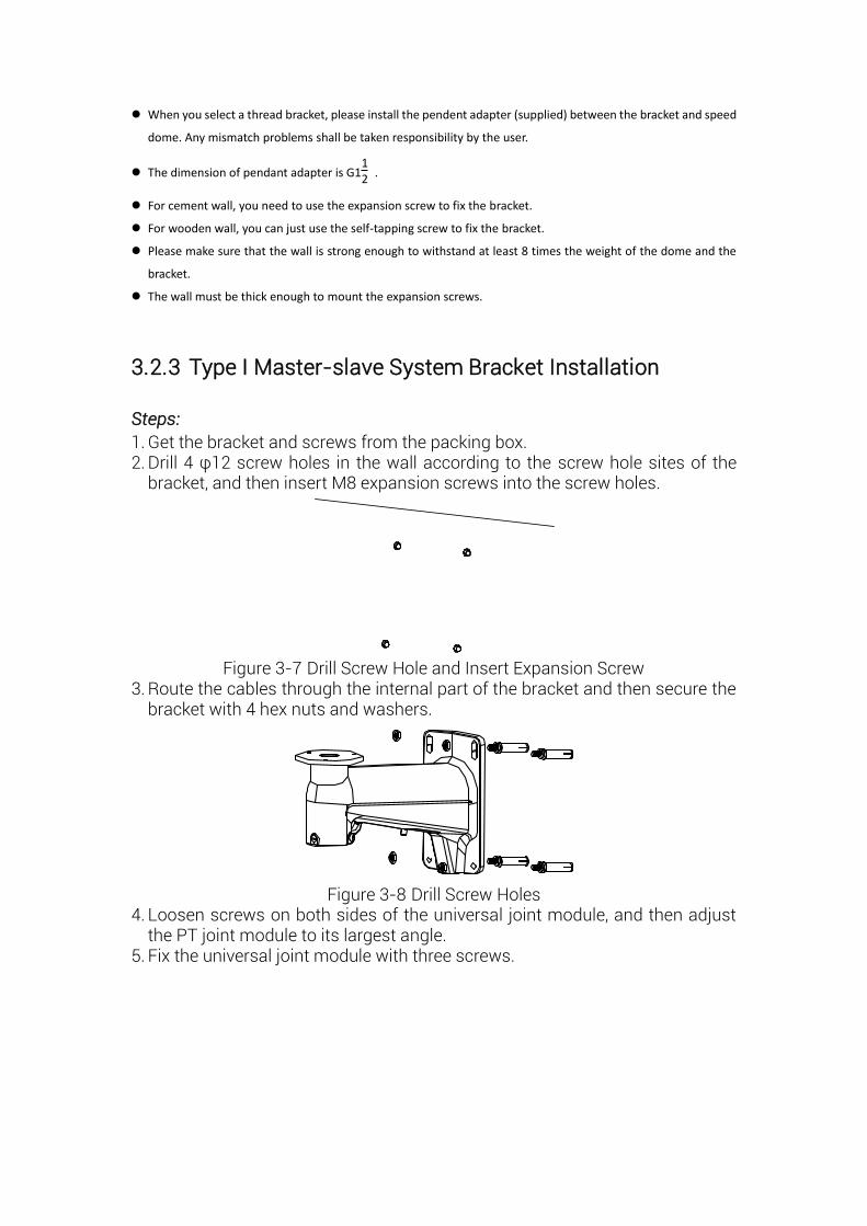
3.2.3 Type I Master-slave System Bracket Installation
Steps:
1. Get the bracket and screws from the packing box. 2. Drill 4 φ12 screw holes in the wall according to the screw hole sites of the
bracket, and then insert M8 expansion screws into the screw holes.
Figure 3-7 Drill Screw Hole and Insert Expansion Screw
3. Route the cables through the internal part of the bracket and then secure the bracket with 4 hex nuts and washers.
Figure 3-8 Drill Screw Holes 4. Loosen screws on both sides of the universal joint module, and then adjust
the PT joint module to its largest angle. 5. Fix the universal joint module with three screws.
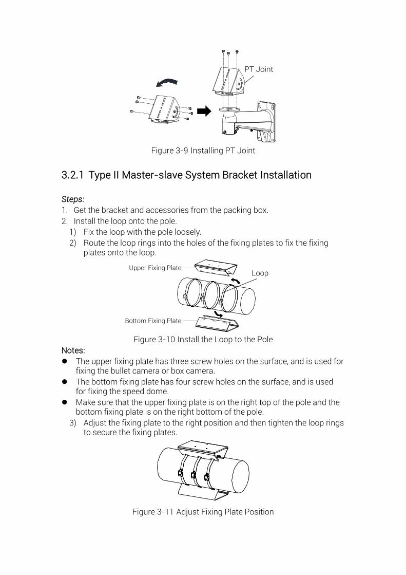
PT Joint
Figure 3-9 Installing PT Joint
3.2.1 Type II Master-slave System Bracket Installation
Steps:
1. Get the bracket and accessories from the packing box.
2. Install the loop onto the pole.
1) Fix the loop with the pole loosely.
2) Route the loop rings into the holes of the fixing plates to fix the fixing plates onto the loop.
LoopUpper Fixing Plate
Bottom Fixing Plate
Figure 3-10 Install the Loop to the Pole
Notes:
The upper fixing plate has three screw holes on the surface, and is used for fixing the bullet camera or box camera.
The bottom fixing plate has four screw holes on the surface, and is used for fixing the speed dome.
Make sure that the upper fixing plate is on the right top of the pole and the bottom fixing plate is on the right bottom of the pole.
3) Adjust the fixing plate to the right position and then tighten the loop rings to secure the fixing plates.
Figure 3-11 Adjust Fixing Plate Position
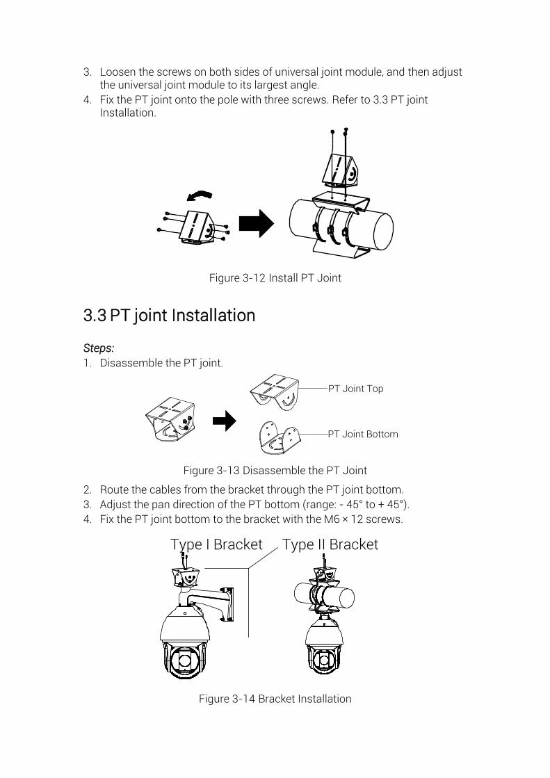
3. Loosen the screws on both sides of universal joint module, and then adjust the universal joint module to its largest angle.
4. Fix the PT joint onto the pole with three screws. Refer to 3.3 PT joint Installation.
Figure 3-12 Install PT Joint
3.3 PT joint Installation
Steps:
1. Disassemble the PT joint.
PT Joint Top
PT Joint Bottom
Figure 3-13 Disassemble the PT Joint
2. Route the cables from the bracket through the PT joint bottom.
3. Adjust the pan direction of the PT bottom (range: - 45° to + 45° ).
4. Fix the PT joint bottom to the bracket with the M6 × 12 screws.
Type I Bracket Type II Bracket
Figure 3-14 Bracket Installation
3.4 Master-slave Tracking System Installation
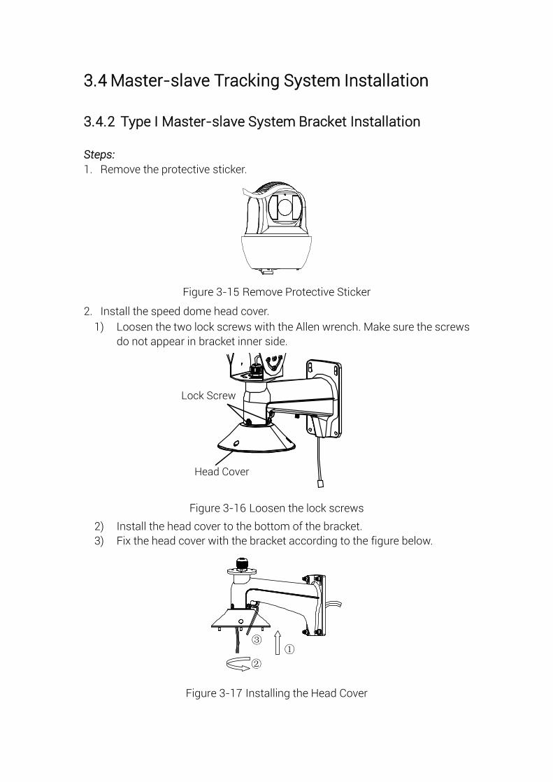
3.4.2 Type I Master-slave System Bracket Installation
Steps:
1. Remove the protective sticker.
Figure 3-15 Remove Protective Sticker
2. Install the speed dome head cover.
1) Loosen the two lock screws with the Allen wrench. Make sure the screws
do not appear in bracket inner side.
Lock Screw
Head Cover
Figure 3-16 Loosen the lock screws
2) Install the head cover to the bottom of the bracket.
3) Fix the head cover with the bracket according to the figure below.
①
②
③
Figure 3-17 Installing the Head Cover
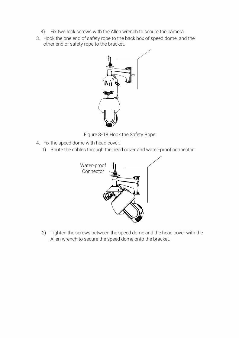
4) Fix two lock screws with the Allen wrench to secure the camera.
3. Hook the one end of safety rope to the back box of speed dome, and the other end of safety rope to the bracket.
Figure 3-18 Hook the Safety Rope
4. Fix the speed dome with head cover.
1) Route the cables through the head cover and water-proof connector.
Water-proof Connector
2) Tighten the screws between the speed dome and the head cover with the
Allen wrench to secure the speed dome onto the bracket.
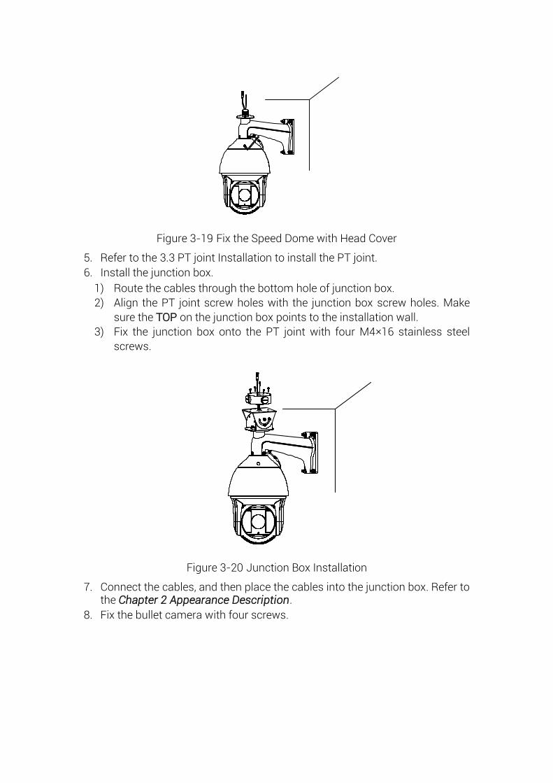
Figure 3-19 Fix the Speed Dome with Head Cover
5. Refer to the 3.3 PT joint Installation to install the PT joint.
6. Install the junction box.
1) Route the cables through the bottom hole of junction box.
2) Align the PT joint screw holes with the junction box screw holes. Make
sure the TOP on the junction box points to the installation wall.
3) Fix the junction box onto the PT joint with four M4× 16 stainless steel
screws.
Figure 3-20 Junction Box Installation
7. Connect the cables, and then place the cables into the junction box. Refer to the Chapter 2 Appearance Description.
8. Fix the bullet camera with four screws.
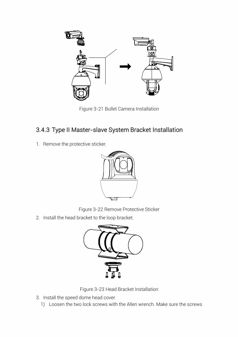
CVBS
Figure 3-21 Bullet Camera Installation
3.4.3 Type II Master-slave System Bracket Installation
1. Remove the protective sticker.
Figure 3-22 Remove Protective Sticker
2. Install the head bracket to the loop bracket.
Figure 3-23 Head Bracket Installation
3. Install the speed dome head cover.
1) Loosen the two lock screws with the Allen wrench. Make sure the screws

do not appear in bracket inner side.
2) Install the head cover to the bottom of the bracket.
3) Fix the head cover with the bracket according to the figure below.
①
②
Figure 3-24 Installing Speed Dome Head Cover
4) Fix two lock screws with the Allen wrench to secure the camera.
4. Hook the one end of safety rope to the back box of speed dome, and the other end of safety rope to the bracket.
Figure 3-25 Hook the Safety Rope
5. Fix the speed dome with head cover.
1) Refer to Chapter 2 to connect the power cable and network cable.
2) Hook the speed dome onto the head cover.
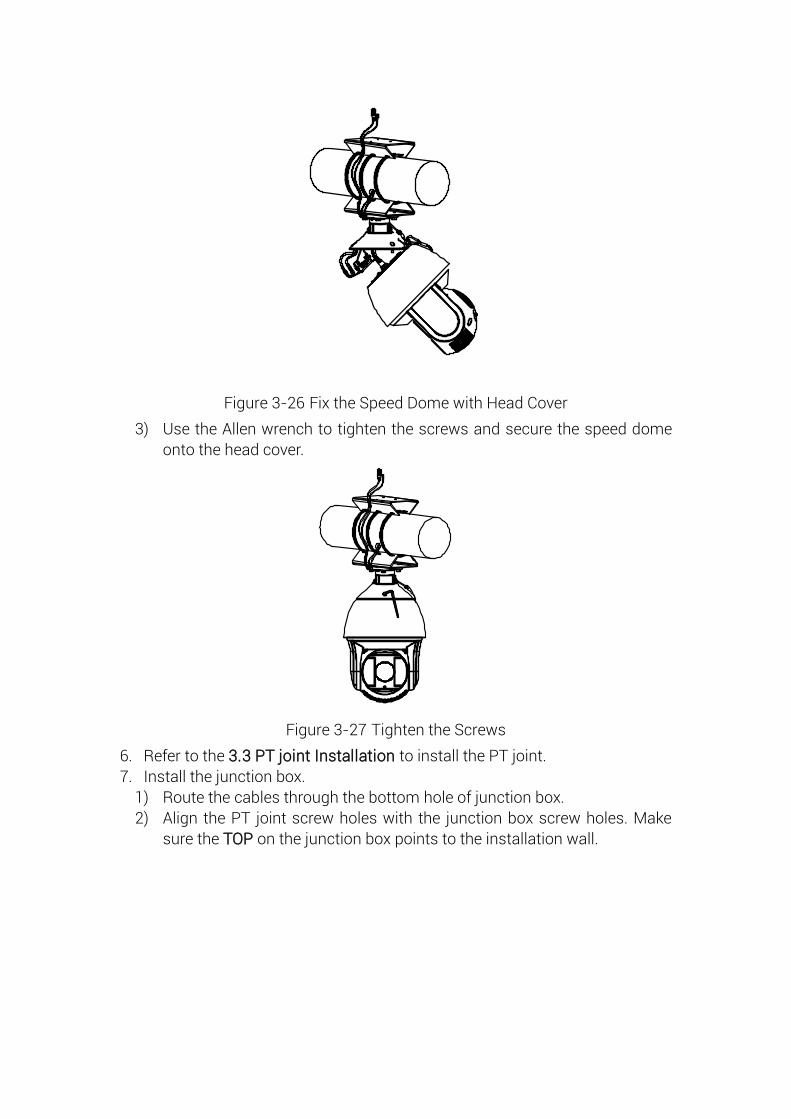
Figure 3-26 Fix the Speed Dome with Head Cover
3) Use the Allen wrench to tighten the screws and secure the speed dome
onto the head cover.
Figure 3-27 Tighten the Screws
6. Refer to the 3.3 PT joint Installation to install the PT joint.
7. Install the junction box.
1) Route the cables through the bottom hole of junction box.
2) Align the PT joint screw holes with the junction box screw holes. Make
sure the TOP on the junction box points to the installation wall.
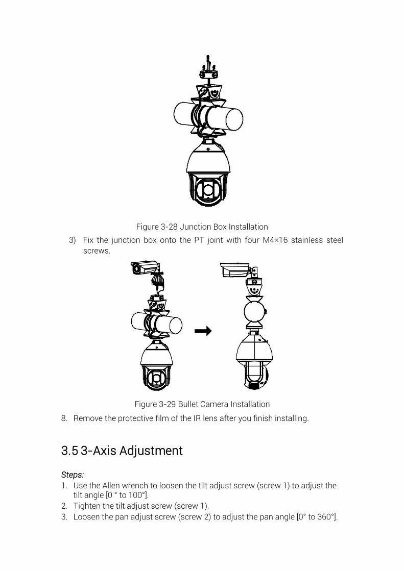
Figure 3-28 Junction Box Installation
3) Fix the junction box onto the PT joint with four M4× 16 stainless steel
screws.
CVBS
Figure 3-29 Bullet Camera Installation
8. Remove the protective film of the IR lens after you finish installing.
3.5 3-Axis Adjustment
Steps:
1. Use the Allen wrench to loosen the tilt adjust screw (screw 1) to adjust the tilt angle [0 ° to 100° ].
2. Tighten the tilt adjust screw (screw 1).
3. Loosen the pan adjust screw (screw 2) to adjust the pan angle [0° to 360° ].
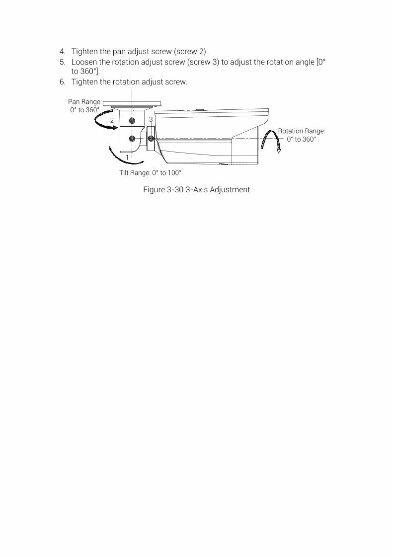
4. Tighten the pan adjust screw (screw 2).
5. Loosen the rotation adjust screw (screw 3) to adjust the rotation angle [0° to 360° ].
6. Tighten the rotation adjust screw.
2 3
1
Tilt Range: 0° to 100°
Rotation Range: 0° to 360°
Pan Range: 0° to 360°
Figure 3-30 3-Axis Adjustment
Chapter 4 Network Connection Before you start:
If you want to set the network speed dome via a LAN (Local Area Network),
please refer to Section 4.1.
If you want to set the network speed dome via a WAN (Wide Area Network),
please refer to Section 4.2.
4.1 Setting the Camera over the LAN
Purpose:
To view and configure the camera via a LAN, you need to connect the network camera in the same subnet with your computer, and install the SADP or client software to search and change the IP of the network camera.
Note: For the detailed introduction of SADP, please refer to Appendix.
4.1.1 Wiring over the LAN
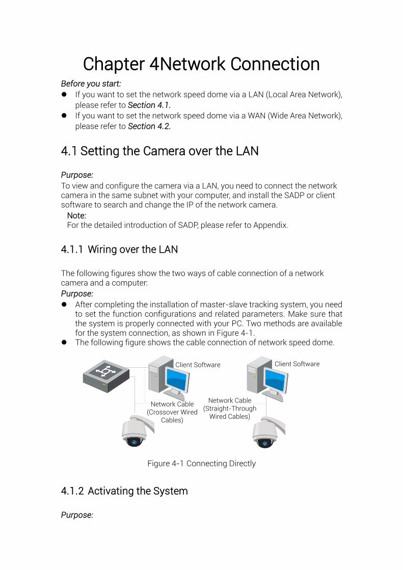
The following figures show the two ways of cable connection of a network camera and a computer:
Purpose:
After completing the installation of master-slave tracking system, you need to set the function configurations and related parameters. Make sure that the system is properly connected with your PC. Two methods are available for the system connection, as shown in Figure 4-1.
The following figure shows the cable connection of network speed dome.
Client Software Client Software
Network Cable (Straight-Through
Wired Cables)
Network Cable (Crossover Wired
Cables)
Figure 4-1 Connecting Directly
4.1.2 Activating the System
Purpose:

You are required to activate the devices first before you can use the system.
Activation via iVMS-4200
Steps:
1. Install the client software from the product CD. You can view the live video and operate the device with the client software.
2. Follow the installation prompts to install the client software and WinPcap. The configuration interface and live view interface of client software are shown below.
Figure 4-2 iVMS-4200 Control Panel
3. Enter Control Panel -> Maintenance and Management ->Device
Management.
4. Click Server tab to enter the server management interface. The online
devices list is shown in Figure 4-3.
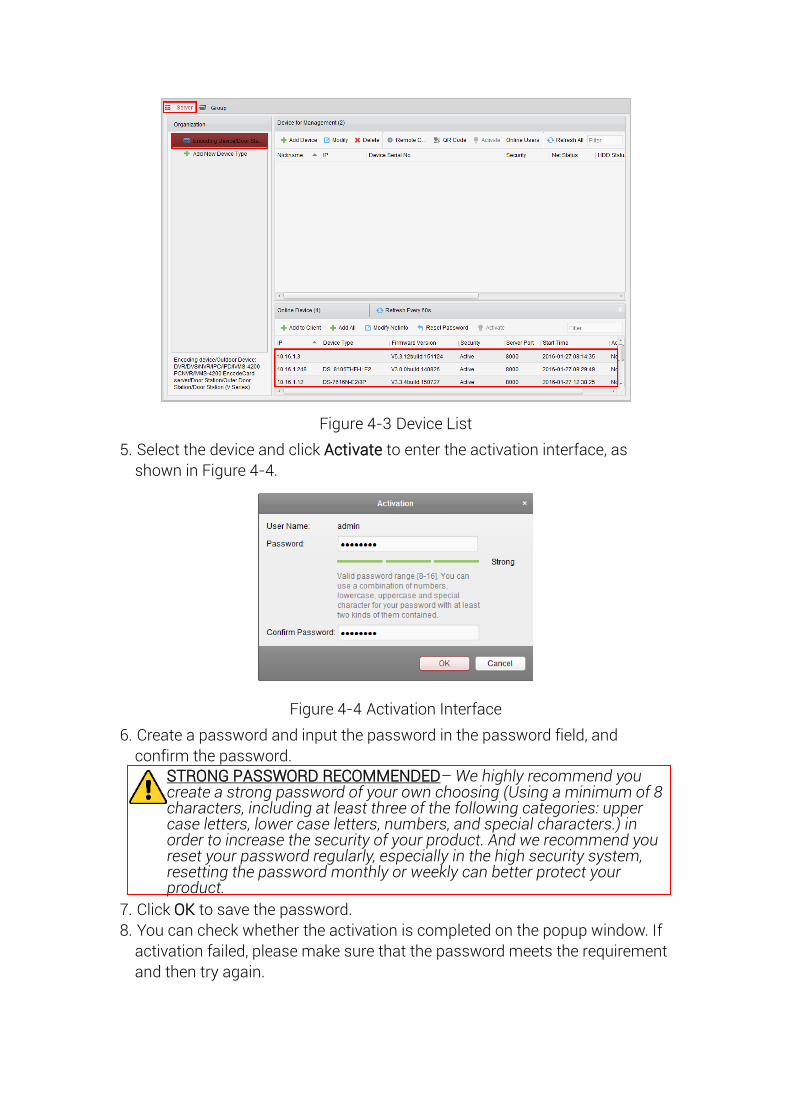
Figure 4-3 Device List
5. Select the device and click Activate to enter the activation interface, as
shown in Figure 4-4.
Figure 4-4 Activation Interface
6. Create a password and input the password in the password field, and
confirm the password.
STRONG PASSWORD RECOMMENDED– We highly recommend you create a strong password of your own choosing (Using a minimum of 8 characters, including at least three of the following categories: upper case letters, lower case letters, numbers, and special characters.) in order to increase the security of your product. And we recommend you reset your password regularly, especially in the high security system, resetting the password monthly or weekly can better protect your product.
7. Click OK to save the password.
8. You can check whether the activation is completed on the popup window. If
activation failed, please make sure that the password meets the requirement
and then try again.

Notes:
If you use third party VMS software, please contact technical support of our branch for camera firmware.
For detailed information about client software of our company, please refer to the user manual of the software. This manual mainly introduces accessing to the network speed dome by web browser.
Activation via Web Browser
Steps:
1. Power on the speed dome, and connect the speed dome to the network.
2. Input the IP address into the address bar of the web browser, and click Enter
to enter the activation interface.
Note: The default IP address of the speed dome is 192.168.1.64.
Figure 4-5 Activation Interface(Web)
3. Create a password and input the password into the password field.
STRONG PASSWORD RECOMMENDED– We highly recommend you create a strong password of your own choosing (Using a minimum of 8 characters, including at least three of the following categories: upper case letters, lower case letters, numbers, and special characters.) in order to increase the security of your product. And we recommend you reset your password regularly, especially in the high security system, resetting the password monthly or weekly can better protect your product.
4. Confirm the password.
5. Click OK to activate the speed dome and enter the live view interface.
Activation via SADP Software
SADP software is used for detecting the online device, activating the device, and resetting the password. Get the SADP software from the supplied disk or the official website, and install the SADP according to the prompts. Follow the steps to activate the speed dome.
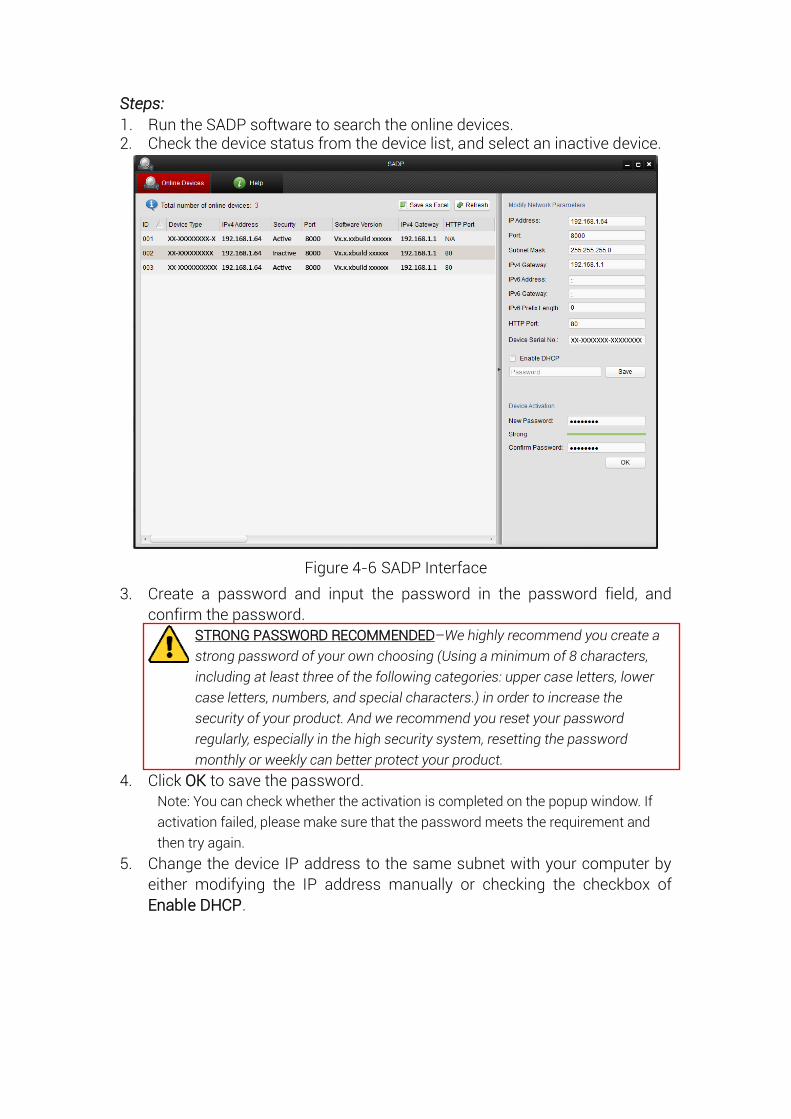
Steps:
1. Run the SADP software to search the online devices. 2. Check the device status from the device list, and select an inactive device.
Figure 4-6 SADP Interface
3. Create a password and input the password in the password field, and
confirm the password.
STRONG PASSWORD RECOMMENDED–We highly recommend you create a
strong password of your own choosing (Using a minimum of 8 characters,
including at least three of the following categories: upper case letters, lower
case letters, numbers, and special characters.) in order to increase the
security of your product. And we recommend you reset your password
regularly, especially in the high security system, resetting the password
monthly or weekly can better protect your product.
4. Click OK to save the password.
Note: You can check whether the activation is completed on the popup window. If
activation failed, please make sure that the password meets the requirement and
then try again.
5. Change the device IP address to the same subnet with your computer by
either modifying the IP address manually or checking the checkbox of
Enable DHCP.
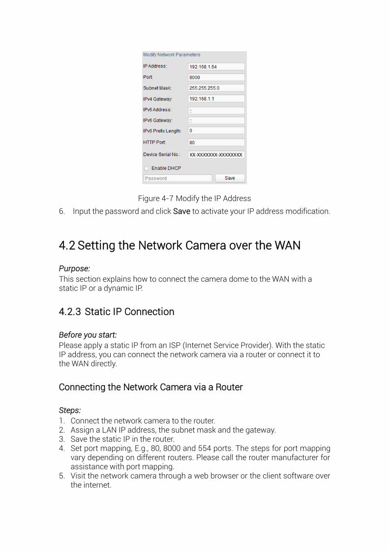
Figure 4-7 Modify the IP Address
6. Input the password and click Save to activate your IP address modification.
4.2 Setting the Network Camera over the WAN
Purpose:
This section explains how to connect the camera dome to the WAN with a static IP or a dynamic IP.
4.2.3 Static IP Connection
Before you start:
Please apply a static IP from an ISP (Internet Service Provider). With the static IP address, you can connect the network camera via a router or connect it to the WAN directly.
Connecting the Network Camera via a Router
Steps:
1. Connect the network camera to the router. 2. Assign a LAN IP address, the subnet mask and the gateway. 3. Save the static IP in the router. 4. Set port mapping, E.g., 80, 8000 and 554 ports. The steps for port mapping
vary depending on different routers. Please call the router manufacturer for assistance with port mapping.
5. Visit the network camera through a web browser or the client software over the internet.
Camera
Network Cable
Router with Static IP
PC
Network Cable
Network Cable
Internet
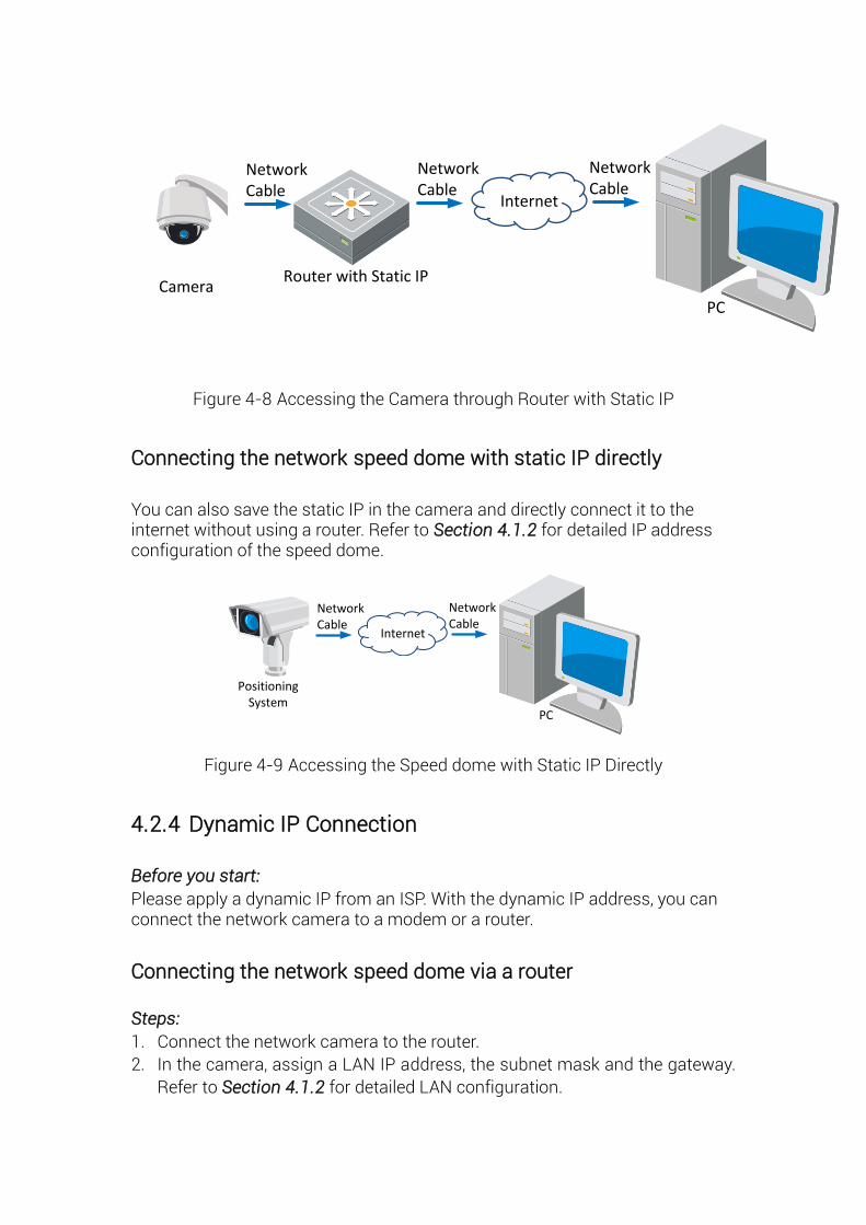
Figure 4-8 Accessing the Camera through Router with Static IP
Connecting the network speed dome with static IP directly
You can also save the static IP in the camera and directly connect it to the internet without using a router. Refer to Section 4.1.2 for detailed IP address configuration of the speed dome.
Positioning System
PC
Network Cable
Network Cable
Internet
Figure 4-9 Accessing the Speed dome with Static IP Directly
4.2.4 Dynamic IP Connection
Before you start:
Please apply a dynamic IP from an ISP. With the dynamic IP address, you can connect the network camera to a modem or a router.
Connecting the network speed dome via a router
Steps:
1. Connect the network camera to the router.
2. In the camera, assign a LAN IP address, the subnet mask and the gateway.
Refer to Section 4.1.2 for detailed LAN configuration.
3. In the router, set the PPPoE user name, password and confirm the password.
For your privacy and to better protect your system against security risks,
we strongly recommend the use of strong passwords for all functions
and network devices. The password should be something of your own
choosing (using a minimum of 8 characters, including upper case
letters, lower case letters, numbers and special characters) in order to
increase the security of your product.
Proper configuration of all passwords and other security settings is the
responsibility of the installer and/or end-user.
4. Set port mapping. E.g. 80, 8000 and 554 ports. The steps for port mapping
vary depending on different routers. Please call the router manufacturer for
assistance with port mapping.
5. Apply a domain name from a domain name provider.
6. Configure the DDNS settings in the setting interface of the router.
7. Visit the camera via the applied domain name.
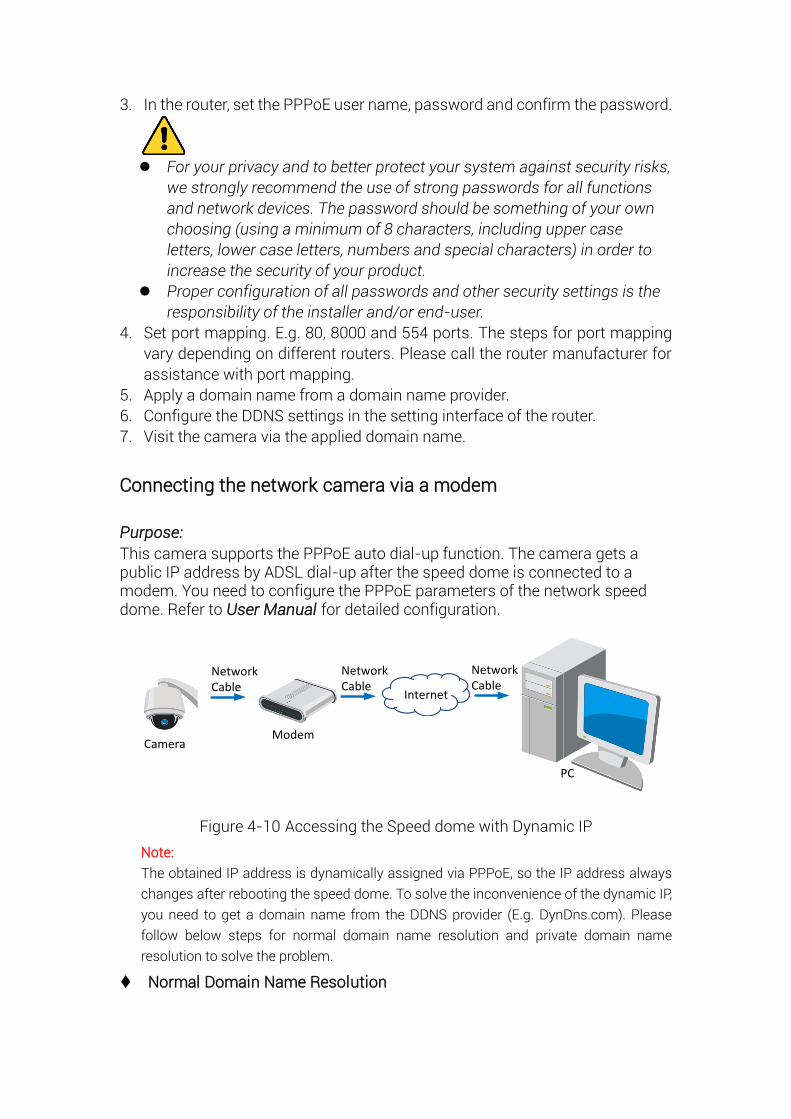
Connecting the network camera via a modem
Purpose:
This camera supports the PPPoE auto dial-up function. The camera gets a public IP address by ADSL dial-up after the speed dome is connected to a modem. You need to configure the PPPoE parameters of the network speed dome. Refer to User Manual for detailed configuration.
Camera
Network Cable
Modem
PC
Network Cable
Network Cable
Internet
Figure 4-10 Accessing the Speed dome with Dynamic IP
Note:
The obtained IP address is dynamically assigned via PPPoE, so the IP address always
changes after rebooting the speed dome. To solve the inconvenience of the dynamic IP,
you need to get a domain name from the DDNS provider (E.g. DynDns.com). Please
follow below steps for normal domain name resolution and private domain name
resolution to solve the problem.
Normal Domain Name Resolution
Camera
Network Cable
Router with Static IP
PC
Network Cable
Network Cable
Internet
(Port Mapping)
Domain Name Resolution Server
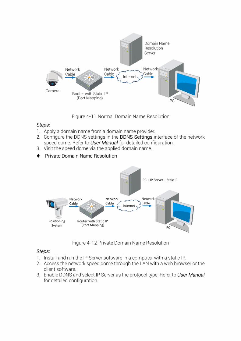
Figure 4-11 Normal Domain Name Resolution
Steps:
1. Apply a domain name from a domain name provider. 2. Configure the DDNS settings in the DDNS Settings interface of the network
speed dome. Refer to User Manual for detailed configuration. 3. Visit the speed dome via the applied domain name.
Private Domain Name Resolution
Positioning System
Network Cable
Router with Static IP
PC
Network Cable
Network Cable
Internet
(Port Mapping)
PC + IP Server + Staic IP
Figure 4-12 Private Domain Name Resolution
Steps:
1. Install and run the IP Server software in a computer with a static IP. 2. Access the network speed dome through the LAN with a web browser or the
client software. 3. Enable DDNS and select IP Server as the protocol type. Refer to User Manual
for detailed configuration.
Chapter 5 System Settings
5.1 Access to the System
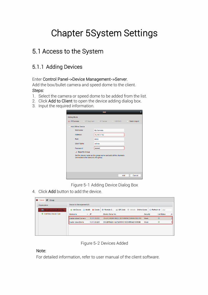
5.1.1 Adding Devices
Enter Control Panel->Device Management->Server.
Add the box/bullet camera and speed dome to the client.
Steps:
1. Select the camera or speed dome to be added from the list. 2. Click Add to Client to open the device adding dialog box. 3. Input the required information.
Figure 5-1 Adding Device Dialog Box
4. Click Add button to add the device.
Figure 5-2 Devices Added
Note:
For detailed information, refer to user manual of the client software.
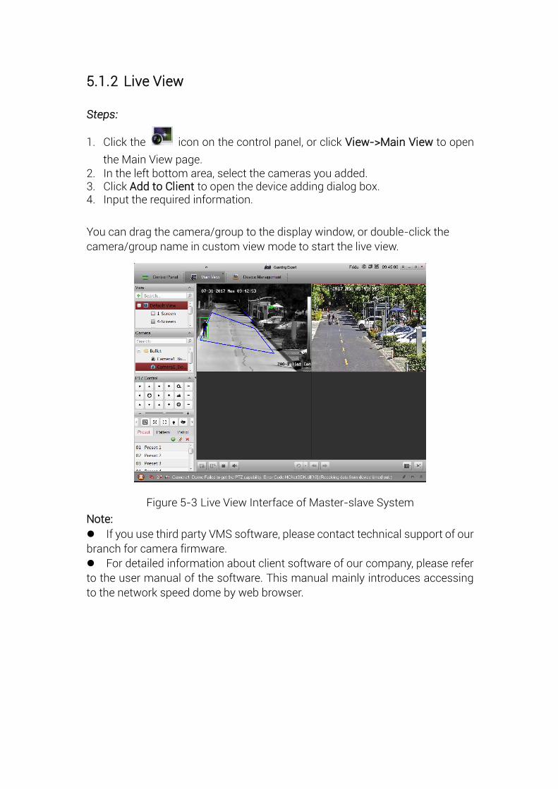
5.1.2 Live View
Steps:
1. Click the icon on the control panel, or click View->Main View to open
the Main View page. 2. In the left bottom area, select the cameras you added. 3. Click Add to Client to open the device adding dialog box. 4. Input the required information.
You can drag the camera/group to the display window, or double-click the
camera/group name in custom view mode to start the live view.
Figure 5-3 Live View Interface of Master-slave System
Note:
If you use third party VMS software, please contact technical support of our
branch for camera firmware.
For detailed information about client software of our company, please refer
to the user manual of the software. This manual mainly introduces accessing
to the network speed dome by web browser.
Chapter 6 Remote Configuration
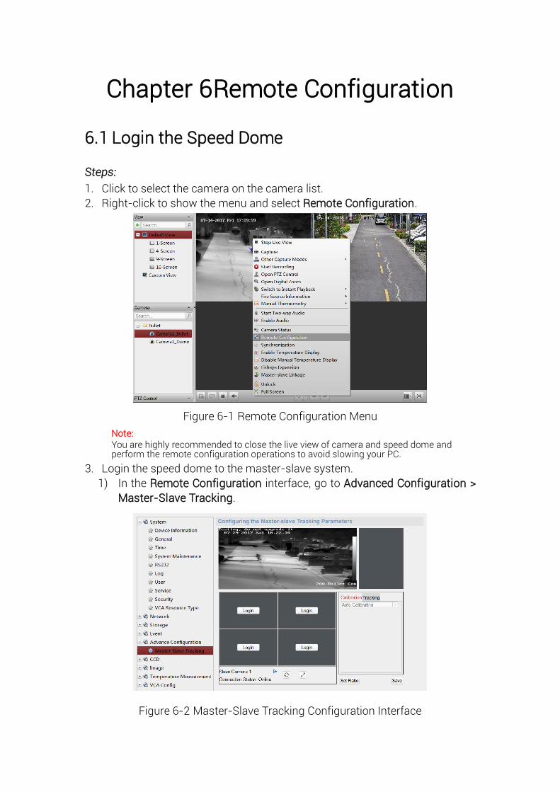
6.1 Login the Speed Dome
Steps:
1. Click to select the camera on the camera list.
2. Right-click to show the menu and select Remote Configuration.
Figure 6-1 Remote Configuration Menu
Note: You are highly recommended to close the live view of camera and speed dome and perform the remote configuration operations to avoid slowing your PC.
3. Login the speed dome to the master-slave system.
1) In the Remote Configuration interface, go to Advanced Configuration >
Master-Slave Tracking.
Figure 6-2 Master-Slave Tracking Configuration Interface
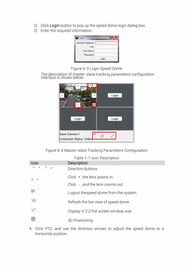
2) Click Login button to pop up the speed dome login dialog box.
3) Enter the required information.
Figure 6-3 Login Speed Dome
The description of master-slave tracking parameters configuration interface is shown below:
Figure 6-4 Master-slave Tracking Parameters Configuration
Table 1-1 Icon Description
Icon Description
Direction Buttons
Click , the lens zooms in.
Click , and the lens zooms out.
Logout thespeed dome from the system.
Refresh the live view of speed dome.
Display in 2:2/full screen window size.
3D Positioning
4. Click PTZ, and use the direction arrows to adjust the speed dome to a
horizontal position.
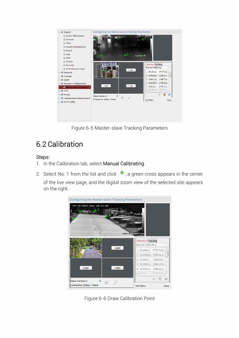
Figure 6-5 Master-slave Tracking Parameters
6.2 Calibration
Steps:
1. In the Calibration tab, select Manual Calibrating.
2. Select No. 1 from the list and click , a green cross appears in the center
of the live view page, and the digital zoom view of the selected site appears
on the right.
Figure 6-6 Draw Calibration Point
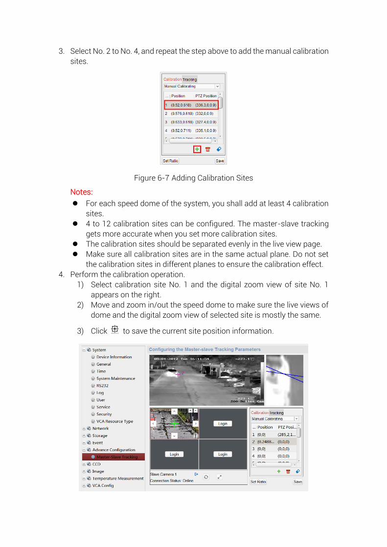
3. Select No. 2 to No. 4, and repeat the step above to add the manual calibration
sites.
Figure 6-7 Adding Calibration Sites
Notes:
For each speed dome of the system, you shall add at least 4 calibration
sites.
4 to 12 calibration sites can be configured. The master-slave tracking
gets more accurate when you set more calibration sites.
The calibration sites should be separated evenly in the live view page.
Make sure all calibration sites are in the same actual plane. Do not set
the calibration sites in different planes to ensure the calibration effect.
4. Perform the calibration operation.
1) Select calibration site No. 1 and the digital zoom view of site No. 1
appears on the right.
2) Move and zoom in/out the speed dome to make sure the live views of
dome and the digital zoom view of selected site is mostly the same.
3) Click to save the current site position information.
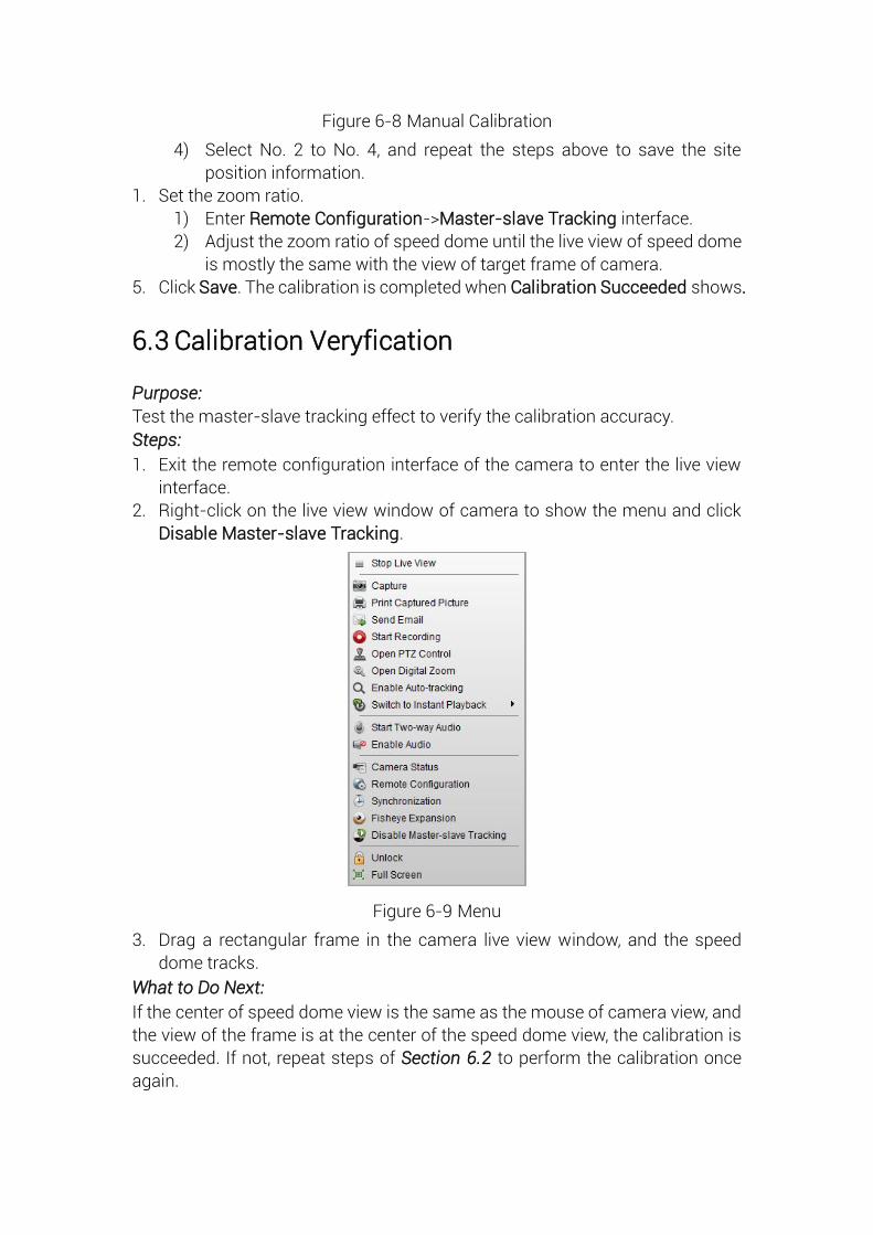
Figure 6-8 Manual Calibration
4) Select No. 2 to No. 4, and repeat the steps above to save the site
position information.
1. Set the zoom ratio.
1) Enter Remote Configuration->Master-slave Tracking interface.
2) Adjust the zoom ratio of speed dome until the live view of speed dome
is mostly the same with the view of target frame of camera.
5. Click Save. The calibration is completed when Calibration Succeeded shows.
6.3 Calibration Veryfication
Purpose:
Test the master-slave tracking effect to verify the calibration accuracy.
Steps:
1. Exit the remote configuration interface of the camera to enter the live view
interface.
2. Right-click on the live view window of camera to show the menu and click
Disable Master-slave Tracking.
Figure 6-9 Menu
3. Drag a rectangular frame in the camera live view window, and the speed
dome tracks.
What to Do Next:
If the center of speed dome view is the same as the mouse of camera view, and
the view of the frame is at the center of the speed dome view, the calibration is
succeeded. If not, repeat steps of Section 6.2 to perform the calibration once
again.
6.4 Set Tracking Parameters
Purpose:
Set the tracking parameters, such as enable the Auto-tracking continuously or
Auto-tracking by Schedule, set tracking time, and Self-adaptive Ratio Coefficient.
Steps:
1. Enable tracking.
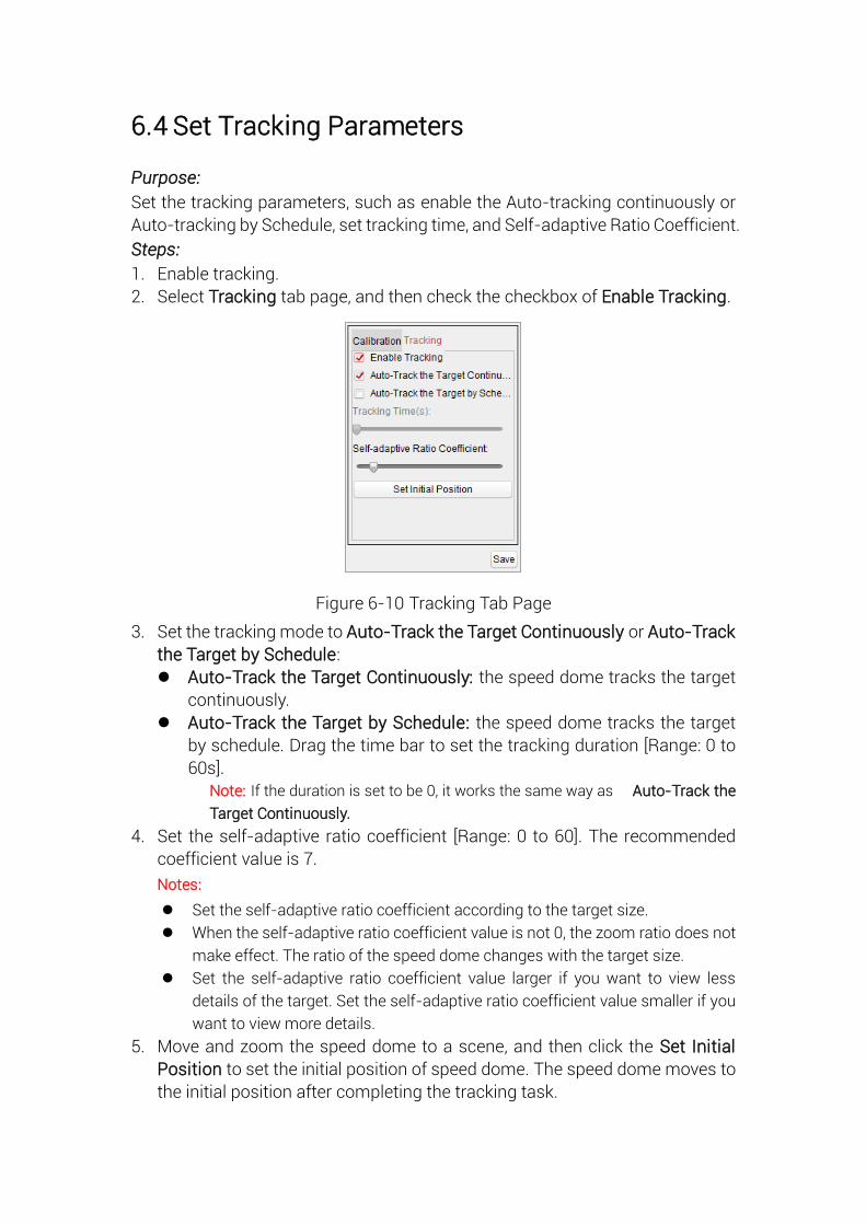
2. Select Tracking tab page, and then check the checkbox of Enable Tracking.
Figure 6-10 Tracking Tab Page
3. Set the tracking mode to Auto-Track the Target Continuously or Auto-Track
the Target by Schedule:
Auto-Track the Target Continuously: the speed dome tracks the target
continuously.
Auto-Track the Target by Schedule: the speed dome tracks the target
by schedule. Drag the time bar to set the tracking duration [Range: 0 to
60s].
Note: If the duration is set to be 0, it works the same way as Auto-Track the
Target Continuously.
4. Set the self-adaptive ratio coefficient [Range: 0 to 60]. The recommended
coefficient value is 7.
Notes:
Set the self-adaptive ratio coefficient according to the target size.
When the self-adaptive ratio coefficient value is not 0, the zoom ratio does not
make effect. The ratio of the speed dome changes with the target size.
Set the self-adaptive ratio coefficient value larger if you want to view less
details of the target. Set the self-adaptive ratio coefficient value smaller if you
want to view more details.
5. Move and zoom the speed dome to a scene, and then click the Set Initial
Position to set the initial position of speed dome. The speed dome moves to
the initial position after completing the tracking task.

6. Click Save to save the settings.
6.5 VCA Rule Configuration
Purpose:
Set the VCA rules of the master-slave tracking, and then the speed dome perform the tracking of target according to the rule.
Steps:
1. Enter Remote Configuration -> VCA Config -> Rule -> Rule Settings.
2. Select Camera No.1, and click of Rule List to add rule.
3. Select Intrusion as Event Type, and then click to draw the zone of
intrusion rule and click Save to save the settings.
Figure 6-11 Setting VCA Rule
4. Set the arming schedule of task. (Optional) 1) Enter Remote Configuration -> VCA Config -> Rule -> Arming Schedule.
2) Select a rule from the rule list.
3) Drag the time bar to set the arming schedule of task.
4) Click Save to save the settings.
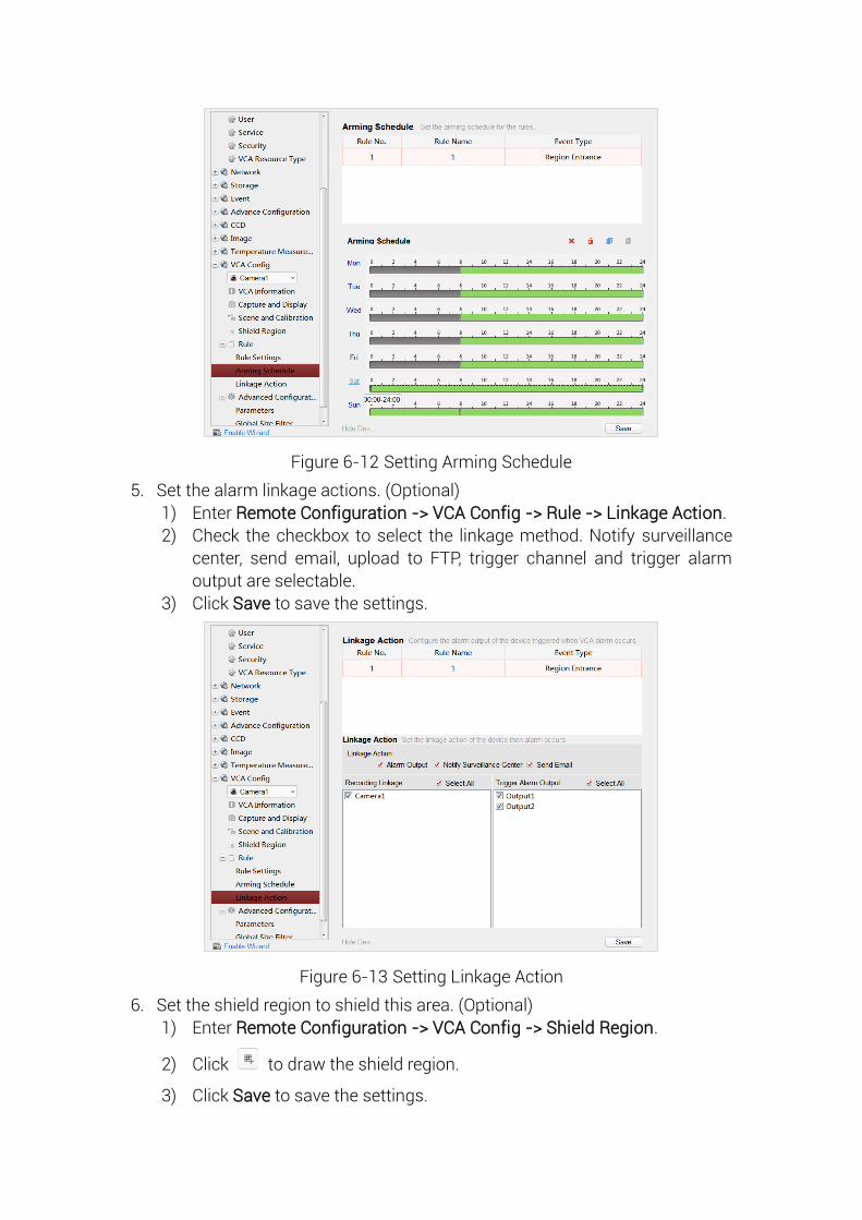
Figure 6-12 Setting Arming Schedule
5. Set the alarm linkage actions. (Optional)
1) Enter Remote Configuration -> VCA Config -> Rule -> Linkage Action.
2) Check the checkbox to select the linkage method. Notify surveillance
center, send email, upload to FTP, trigger channel and trigger alarm
output are selectable.
3) Click Save to save the settings.
Figure 6-13 Setting Linkage Action
6. Set the shield region to shield this area. (Optional)
1) Enter Remote Configuration -> VCA Config -> Shield Region.
2) Click to draw the shield region.
3) Click Save to save the settings.
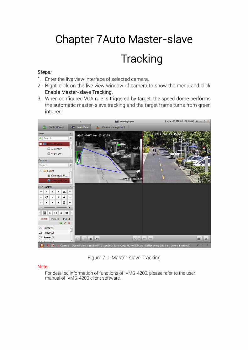
Chapter 7 Auto Master-slave
Tracking Steps:
1. Enter the live view interface of selected camera.
2. Right-click on the live view window of camera to show the menu and click
Enable Master-slave Tracking.
3. When configured VCA rule is triggered by target, the speed dome performs
the automatic master-slave tracking and the target frame turns from green
into red.
Figure 7-1 Master-slave Tracking
Note:
For detailed information of functions of iVMS-4200, please refer to the user manual of iVMS-4200 client software.
Appendix
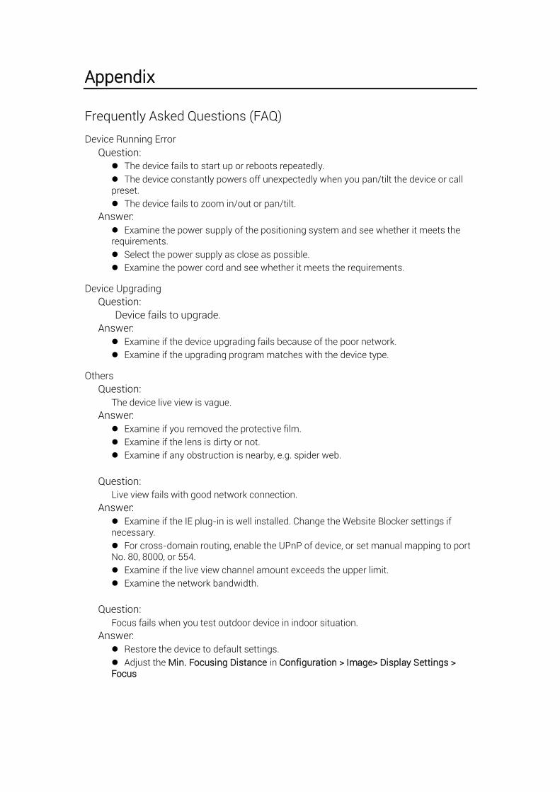
Frequently Asked Questions (FAQ)
Device Running Error
Question:
The device fails to start up or reboots repeatedly.
The device constantly powers off unexpectedly when you pan/tilt the device or call preset.
The device fails to zoom in/out or pan/tilt.
Answer:
Examine the power supply of the positioning system and see whether it meets the requirements.
Select the power supply as close as possible.
Examine the power cord and see whether it meets the requirements.
Device Upgrading
Question:
Device fails to upgrade.
Answer:
Examine if the device upgrading fails because of the poor network.
Examine if the upgrading program matches with the device type.
Others
Question:
The device live view is vague.
Answer:
Examine if you removed the protective film.
Examine if the lens is dirty or not.
Examine if any obstruction is nearby, e.g. spider web.
Question:
Live view fails with good network connection.
Answer:
Examine if the IE plug-in is well installed. Change the Website Blocker settings if necessary.
For cross-domain routing, enable the UPnP of device, or set manual mapping to port No. 80, 8000, or 554.
Examine if the live view channel amount exceeds the upper limit.
Examine the network bandwidth.
Question:
Focus fails when you test outdoor device in indoor situation.
Answer:
Restore the device to default settings.
Adjust the Min. Focusing Distance in Configuration > Image> Display Settings > Focus
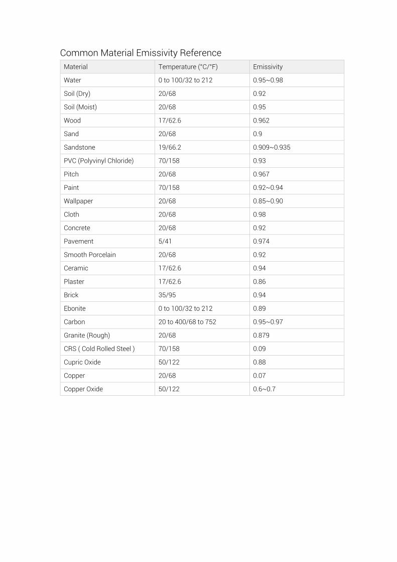
Common Material Emissivity Reference
Material Temperature (° C/° F) Emissivity
Water 0 to 100/32 to 212 0.95~0.98
Soil (Dry) 20/68 0.92
Soil (Moist) 20/68 0.95
Wood 17/62.6 0.962
Sand 20/68 0.9
Sandstone 19/66.2 0.909~0.935
PVC (Polyvinyl Chloride) 70/158 0.93
Pitch 20/68 0.967
Paint 70/158 0.92~0.94
Wallpaper 20/68 0.85~0.90
Cloth 20/68 0.98
Concrete 20/68 0.92
Pavement 5/41 0.974
Smooth Porcelain 20/68 0.92
Ceramic 17/62.6 0.94
Plaster 17/62.6 0.86
Brick 35/95 0.94
Ebonite 0 to 100/32 to 212 0.89
Carbon 20 to 400/68 to 752 0.95~0.97
Granite (Rough) 20/68 0.879
CRS ( Cold Rolled Steel ) 70/158 0.09
Cupric Oxide 50/122 0.88
Copper 20/68 0.07
Copper Oxide 50/122 0.6~0.7

43