optical semiconductor devices - rs...
TRANSCRIPT

145
Optical Semiconductor Devices
Visible Laser Diodes 146 Visible LEDs 147
Photo Sensors 156 Photo Couplers & Photo Relays 159
Fiber-Optic Devices (TOSLINK™) 186 Image Sensors 190

146
Visible Laser Diodes
Maximum Ratings (Tc = 25°C) Electrical/Optical Characteristics (Tc = 25°C)
Beam divergence
Optical output power
Case temperature
Threshold current
Operation current
Peak lasing wavelength Pararell Perpendicular
Monitor current Test condition
Remarks
Symbol Po Tc Ith Iop λp θ // θ⊥ Im Po
Unit (mW) (°C) (mA) (mA) (nm) ( ° ) ( ° ) (mA) (mW)
Part Number (Note 1) ⎯ ⎯ Typ. Typ. Typ. Typ. Typ. Typ. ⎯
TOLD9462MD 7 −10 to 70 23 30 650 8 28 0.18 5 for DVD
7 25 35 650 9 28 0.15 5 TOLD2000MDA/SDA
7 −10 to 70
20 35 790 10 32 0.35 5
Dual-wavelength laser
for DVD
7 25 35 650 9 28 0.05 5 TOLD2000FDA
7 −10 to 70
20 35 790 10 32 0.10 5
Dual-wavelength laser
for DVD
7 40 50 655 9 28 0.15 5 TOLD2003SDA
7 −30 to 85
35 55 790 10 32 0.35 5 for DVD-Navigation
TOLD9456ME/TE 100 (pulse: 200) −10 to 75 50 130 658 9.5 17.5 ⎯ (Note 2) 80 for Rewritable-DVD
** TOLD9457ME 100 (pulse: 250) −10 to 75 50 130 658 9.5 17.5 ⎯ (Note 2) 80 for Rewritable-DVD
Note 1: MD, MDA and ME: φ5.6-mm metal can package, SDA: D-cut metal can package, TE: I-cut metal can package, FDA: Lead frame package **: Under development
Note 2: The TOLD9456ME/TE, TOLD9457ME do not incorporate monitor photodiodes.
For applications other than optical disk systems, please contact your nearest Toshiba sales office.

147
Visible LEDs
Dual-Color LED Lamps Intensity
lv (mcd) @IF = 20 mA Part Number
Typical Emitting Wavelength
Color of Emitted Light
Min Typ.
Viewing Angle 2θ1/2 No rank specified λd (nm) λp (nm)
Lens Type Maximum DC Forward Current Rating IF (mA)
@Ta = 25°C Typical Applications
476/272 1100/500 30°/30° TLRMHGH48T(F) 626/571 636/574 Transparent 50 (total) Red/Green
272/153 450/220 40°/40° TLRMHGH48M(F) 626/571 636/574 Milky white, diffusing 50 (total) Message boards

148
High-Brightness LED Lamps ( φ5 ) Intensity
lv (mcd) @IF = 20 mA Part Number
Typical Emitting Wavelength
Color of Emitted Light
Min Typ.
Viewing Angle 2θ1/2 No rank specified Two ranks specified λd (nm) λp (nm)
Lens Type Maximum DC Forward Current Rating IF (mA)
@Ta = 25°C Typical Applications
1530 4500 6° TLSU180P(F) TLSU180P(TU,F) 623 636 Transparent 30
4760 11000 TLSH20TP(F) 613 623 Transparent 50
2720 9000 TLRMH20TP(F) 626 636 Transparent 50
2720 9000 TLSE20TP(F) 613 623 Transparent 50
4760 12000 TLRME20CP(F) 626 636 Red, transparent 50
2720 8000 TLRME20TP(F) 626 636 Transparent 50
2720 7000
7°
TLRE20TP(F) 630 644 Transparent 50
2720 10000 TLSH180P(F) TLSH180P(VW,F) 613 623 Transparent 50
1530 8000 TLSE180P(F) 613 623 Transparent 50
1530 5000 TLRH180P(F) TLRH180P(UV,F) 630 644 Transparent 50
850 3000
8°
TLRE180AP(F) TLRE180AP(TU,F) 630 644 Transparent 50
2720 6500 TLSH38TP(F) 613 623 Transparent 50
1530 4800 12°
TLRMH38TP(F) 626 636 Transparent 50
1530 4200 15° TLRMH151P(F) 626 636 Transparent 50
1530 4500 TLSH17TP(F) 613 623 Transparent 50
850 3200 TLRMH17TP(F) 626 636 Transparent 50
850 3000 TLSE17TP(F) 613 623 Transparent 50
850 2400 TLRME17TP(F) 626 636 Transparent 50
476 1500 TLRE17TP(F) 630 644 Transparent 50
272 900 TLSU156P(F) TLSU156P(QR,F) 623 636 Transparent 30
85 270
20°
TLRE138P(F) 630 644 Red, diffusing 50
Pilot lamps
(narrow range)
850 2700 TLSH157P(F) TLSH157P(ST,F) 613 623 Transparent 50
850 2240 TLRMH157P(F) 626 636 Transparent 50
476 1900 TLSE157P(F) TLSE157P(ST,F) 613 623 Transparent 50
476 1700 TLRH157P(F) TLRH157P(ST,F) 630 644 Transparent 50
272 1000
22°
TLRE157AP(F) TLRE157AP(RS,F) 630 644 Transparent 50
850 1900 TLSH16TP(F) 613 623 Transparent 50
476 1500 TLRMH16TP(F) 626 636 Transparent 50
476 1500 TLSE16TP(F) 613 623 Transparent 50
476 1000 TLSE16CP(F) 613 623 Red, transparent 50
476 900 TLRMH156P(F) 626 636 Transparent 50
272 1200 TLRME16TP(F) 626 636 Transparent 50
272 800 TLRE16TP(F) 630 644 Transparent 50
272 800 TLRME16CP(F) 626 636 Red, transparent 50
153 600 TLRE16CP(F) 630 644 Red, transparent 50
153 500
25°
TLRME17DP(F) 626 636 Red, diffusing 50
476 1400 TLSH156P(F) TLSH156P(RS,F) 613 623 Transparent 50
272 900 TLSE156P(F) TLSE156P(RS,F) 613 623 Transparent 50
272 800 TLRH156P(F) TLRH156P(QR,F) 630 644 Transparent 50
153 550 TLSU113P(F) 623 636 Red, transparent 30
153 450
30°
TLRE156AP(F) TLRE156AP(PQ,F) 630 644 Transparent 50
272 650 35° TLRMH265P(F) 626 636 Milky-white, diffusing 50
47.6 250 40° TLSU114P(F) TLSU114P(NP,F) 623 636 Red, diffusing 30
Message boards
Back lighting
47.6 150 75° TLRE25TP(F) 630 644 Transparent 50
27.2 80 90° TLRE263AP(F) TLRE263AP(MN,F) 630 644 Transparent 50
8.5 20 130° TLRE11TP(F) 630 644 Transparent 50
Red
8.5 15 150° TLRE261AP(F) 630 644 Transparent 50
Back lighting
(wide range)
2720 7000 6° TLOU180P(F) TLOU180P(UV,F) 605 612 Transparent 30
4760 15000 TLOH20TP(F) 605 612 Transparent 50
4760 10000 7°
TLOE20TP(F) 605 612 Transparent 50
2720 10000 TLOH180P(F) TLOH180P(VW,F) 605 612 Transparent 50
1530 7000 8°
TLOE180AP(F) TLOE180AP(UV,F) 605 612 Transparent 50
2720 7500 12° TLOH38TP(F) 605 612 Transparent 50
1530 3500 TLOE17CP(F) 605 612 Orange, transparent 50
1530 5000 TLOH17TP(F) 605 612 Transparent 50
1530 4500 TLOE17TP(F) 605 612 Transparent 50
476 900 TLOU156P(F) TLOU156P(RS,F) 605 612 Transparent 30
476 800
20°
TLOU172P(F) 605 612 Orange, transparent 30
Pilot lamps
(narrow range)
850 2800 TLOH157P(F) TLOH157P(TU,F) 605 612 Transparent 50
476 2800 22°
TLOE157AP(F) TLOE157AP(ST,F) 605 612 Transparent 50
850 2300 TLOH16TP(F) 605 612 Transparent 50
850 2000 TLOE16TP(F) 605 612 Transparent 50
Orange
476 1600
25°
TLOE16CP(F) 605 612 Orange, transparent 50
Message boards
Back lighting
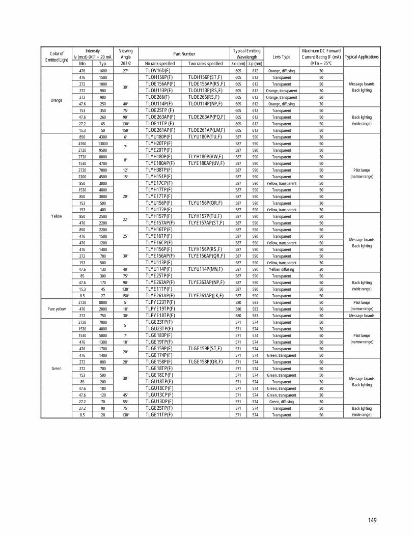
149
Intensity
lv (mcd) @IF = 20 mA Part Number
Typical Emitting Wavelength
Color of Emitted Light
Min Typ.
Viewing Angle 2θ1/2 No rank specified Two ranks specified λd (nm) λp (nm)
Lens Type Maximum DC Forward Current Rating IF (mA)
@Ta = 25°C Typical Applications
476 1600 27° TLOV16D(F) 605 612 Orange, diffusing 30
476 1500 TLOH156P(F) TLOH156P(ST,F) 605 612 Transparent 50
272 1000 TLOE156AP(F) TLOE156AP(RS,F) 605 612 Transparent 50
272 900 TLOU113P(F) TLOU113P(RS,F) 605 612 Orange, transparent 30
272 900
30°
TLOE266(F) TLOE266(RS,F) 605 612 Orange, transparent 50
47.6 250 40° TLOU114P(F) TLOU114P(NP,F) 605 612 Orange, diffusing 30
Message boards
Back lighting
153 350 75° TLOE25TP (F) 605 612 Transparent 50
47.6 260 90° TLOE263AP(F) TLOE263AP(PQ,F) 605 612 Transparent 50
27.2 65 130° TLOE11TP (F) 605 612 Transparent 50
Orange
15.3 50 150° TLOE261AP(F) TLOE261AP(LM,F) 605 612 Transparent 50
Back lighting
(wide range)
850 4300 6° TLYU180P(F) TLYU180P(TU,F) 587 590 Transparent 30
4760 13000 TLYH20TP(F) 587 590 Transparent 50
2720 9500 7°
TLYE20TP(F) 587 590 Transparent 50
2720 8000 TLYH180P(F) TLYH180P(VW,F) 587 590 Transparent 50
1530 4700 8°
TLYE180AP(F) TLYE180AP(UV,F) 587 590 Transparent 50
2720 7000 12° TLYH38TP(F) 587 590 Transparent 50
2200 4500 15° TLYH151P(F) 587 590 Transparent 50
850 3000 TLYE17CP(F) 587 590 Yellow, transparent 50
1530 4800 TLYH17TP(F) 587 590 Transparent 50
850 3000 TLYE17TP(F) 587 590 Transparent 50
153 500 TLYU156P(F) TLYU156P(QR,F) 587 590 Transparent 30
153 400
20°
TLYU172P(F) 587 590 Yellow, transparent 30
Pilot lamps
(narrow range)
850 2500 TLYH157P(F) TLYH157P(TU,F) 587 590 Transparent 50
476 2200 22°
TLYE157AP(F) TLYE157AP(ST,F) 587 590 Transparent 50
850 2200 TLYH16TP(F) 587 590 Transparent 50
476 1500 TLYE16TP(F) 587 590 Transparent 50
476 1200
25°
TLYE16CP(F) 587 590 Yellow, transparent 50
476 1400 TLYH156P(F) TLYH156P(RS,F) 587 590 Transparent 50
272 700 TLYE156AP(F) TLYE156AP(QR,F) 587 590 Transparent 50
153 500
30°
TLYU113P(F) 587 590 Yellow, transparent 30
47.6 130 40° TLYU114P(F) TLYU114P(MN,F) 587 590 Yellow, diffusing 30
Message boards
Back lighting
85 300 75° TLYE25TP(F) 587 590 Transparent 50
47.6 170 90° TLYE263AP(F) TLYE263AP(NP,F) 587 590 Transparent 50
15.3 45 130° TLYE11TP(F) 587 590 Transparent 50
Yellow
8.5 27 150° TLYE261AP(F) TLYE261AP(JK,F) 587 590 Transparent 50
Back lighting
(wide range)
2720 8000 5° TLPYE23TP(F) 580 583 Transparent 50
476 2000 18° TLPYE19TP(F) 580 583 Transparent 50
Pilot lamps
(narrow range) Pure yellow
272 750 30° TLPYE18TP(F) 580 583 Transparent 50 Message boards
2720 7000 TLGE23TP(F) 571 574 Transparent 50
1530 4000 5°
TLGU23TP(F) 571 574 Transparent 30
1530 5000 7° TLGE183P(F) 571 574 Transparent 50
476 1300 18° TLGE19TP(F) 571 574 Transparent 50
476 1700 TLGE159P(F) TLGE159P(ST,F) 571 574 Transparent 50
476 1400 20°
TLGE174P(F) 571 574 Green, transparent 50
Pilot lamps
(narrow range)
272 800 28° TLGE158P(F) TLGE158P(QR,F) 571 574 Transparent 50
272 700 TLGE18TP(F) 571 574 Transparent 50
153 500 TLGE18CP(F) 571 574 Green, transparent 50
85 200 TLGU18TP(F) 571 574 Transparent 30
47.6 180
30°
TLGU18CP(F) 571 574 Green, transparent 30
47.6 120 45° TLGU13CP(F) 571 574 Green, transparent 30
27.2 70 55° TLGU13DP(F) 571 574 Green, diffusing 30
Message boards
Back lighting
27.2 90 75° TLGE25TP(F) 571 574 Transparent 50
Green
8.5 20 130° TLGE11TP(F) 571 574 Transparent 50
Back lighting
(wide range)
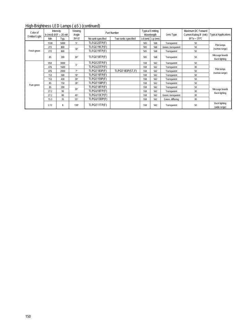
150
High-Brightness LED Lamps ( φ5 ) (continued) Intensity
lv (mcd) @IF = 20 mA Part Number
Typical Emitting Wavelength
Color of Emitted Light
Min Typ.
Viewing Angle 2θ1/2 No rank specified Two ranks specified λd (nm) λp (nm)
Lens Type Maximum DC Forward Current Rating IF (mA)
@Ta = 25°C Typical Applications
1530 5000 5° TLFGE23TP(F) 565 568 Transparent 50
272 800 TLFGE19CP(F) 565 568 Green, transparent 50
272 800 18°
TLFGE19TP(F) 565 568 Transparent 50
Pilot lamps
(narrow range) Fresh green
85 300 30° TLFGE18TP(F) 565 568 Transparent 50 Message boards
Back lighting
850 3000 TLPGE23TP(F) 558 562 Transparent 50
476 1600 5°
TLPGU23TP(F) 558 562 Transparent 30
476 2000 7° TLPGE183P(F) TLPGE183P(ST,F) 558 562 Transparent 50
153 500 18° TLPGE19TP(F) 558 562 Transparent 50
153 430 20° TLPGE159P(F) 558 562 Transparent 50
Pilot lamps
(narrow range)
85 150 28° TLPGE158P(F) 558 562 Transparent 50
85 200 TLPGE18TP(F) 558 562 Transparent 50
27.2 90 30°
TLPGU18TP(F) 558 562 Transparent 30
27.2 80 45° TLPGU13CP(F) 558 562 Green, transparent 30
15.3 35 55° TLPGU13DP(F) 558 562 Green, diffusing 30
Message boards
Back lighting
Pure green
2.72 8 130° TLPGE11TP(F) 558 562 Transparent 50 Back lighting
(wide range)

151
High-Brightness LED Lamps ( φ3 ) Intensity
lv (mcd) @IF = 20 mA Part Number
Typical Emitting Wavelength
Color of Emitted Light
Min Typ.
Viewing Angle 2θ1/2 No rank specified Two ranks specified λd (nm) λp (nm)
Lens Type Maximum DC Forward Current Rating IF (mA)
@Ta = 25°C Typical Applications
476 4000 TLSU163(F) 623 636 Pale red, transparent 30
476 1600 9°
TLSU160(F) 623 636 Transparent 30
2720 4500 TLSH160(F) 613 623 Transparent 50
850 1800 TLRH160(F) TLRH160(ST,F) 630 644 Transparent 50
476 1200
10°
TLRE160A(F) TLRE160A(RS,F) 630 644 Transparent 50
1530 3500 TLRME50C(F) 626 636 Red, transparent 50
1530 3500 TLSE50T(F) 613 623 Transparent 50
850 2200 TLRME50T(F) 626 636 Transparent 50
850 1800
16°
TLRE50T(F) 630 644 Transparent 50
153 450 18° TLSU164(F) 623 636 Pale red, diffusing 30
153 300 TLSU125(F) TLSU125(PQ,F) 623 636 Transparent 30
85 270 35°
TLSU123(F) TLSU123(PQ,F) 623 636 Red, transparent 30
272 800 TLSH125(F) 613 623 Transparent 50
85 180 TLSU126(F) 623 636 Milky-white, diffusing 30
47.6 100
40°
TLSU124(F) TLSU124(MN,F) 623 636 Red, diffusing 30
272 800 TLSE53T(F) 613 623 Transparent 50
272 600 TLRME53T(F) 626 636 Transparent 50
153 400
45°
TLRE53T(F) 630 644 Transparent 50
Pilot lamps
47.6 170 60° TLSU262(F) TLSU262(NP,F) 623 636 Transparent 30
85 330 TLRME68TG(F)♦ 626 636 Transparent 50
85 260 TLRME68CG(F)♦ 626 636 Red, transparent 50
85 220 TLRH262(F) TLRH262(NP,F) 630 644 Transparent 50
85 200 TLSE62T(F) 613 623 Transparent 50
47.6 180 TLRME62T(F) 626 636 Transparent 50
47.6 150 TLRE262A(F) TLRE262A(MN,F) 630 644 Transparent 50
47.6 130 TLSU268G(F)♦ 623 636 Transparent 30
47.6 120
80°
TLRE62T(F) 630 644 Transparent 50
47.6 140 100° TLRME68DG(F)♦ 626 636 Red, diffusing 50
15.3 45 120° TLRE60T(F) 630 644 Transparent 50
8.5 25 140° TLRE260A(F) 630 644 Transparent 50
Back lighting
(wide range)
Red
27.2 100 40°/20° TLSU225(F) 623 636 Transparent 50 Side view
476 2500 9° TLOU160(F) 605 612 Transparent 30
850 2300 TLOH160(F) TLOH160(TU,F) 605 612 Transparent 50
476 1500 10°
TLOE160A(F) TLOE160A(ST,F) 605 612 Transparent 50
2720 7000 TLOE50C(F) 605 612 Orange, transparent 50
1530 4500 16°
TLOE50T(F) 605 612 Transparent 50
85 400 35° TLOU123(F) 605 612 Orange, transparent 30
47.6 180 40° TLOU124(F) 605 612 Orange, diffusing 30
272 1000 45° TLOE53T(F) 605 612 Transparent 50
Pilot lamps
47.6 300 TLOU262(F) TLOU262(PQ,F) 605 612 Transparent 30
47.6 200 60°
TLOU267(F) 605 612 Orange, transparent 30
153 450 TLOH262(F) TLOH262(PQ,F) 605 612 Transparent 50
153 350 TLOE62T(F) 605 612 Transparent 50
85 300
80°
TLOE262A(F) TLOE262A(PQ,F) 605 612 Transparent 50
27.2 100 120° TLOE60T(F) 605 612 Transparent 50
Orange
15.3 70 140° TLOE260A(F) TLOE260A(LM,F) 605 612 Transparent 50
Back lighting
(wide range)
476 1500 9° TLYU160(F) TLYU160(ST,F) 587 590 Transparent 30
850 4300 TLYH160(F) TLYH160(TU,F) 587 590 Transparent 50
476 2300 10°
TLYE160A(F) TLYE160A(ST,F) 587 590 Transparent 50
1530 3500 TLYE50C(F) 587 590 Yellow, transparent 50
1530 3500 16°
TLYE50T(F) 587 590 Transparent 50
85 220 35° TLYU123(F) TLYU123(NP,F) 587 590 Yellow, transparent 30
47.6 110 40° TLYU124(F) TLYU124(MN,F) 587 590 Yellow, diffusing 30
272 800 45° TLYE53T(F) 587 590 Transparent 50
Pilot lamps
47.6 150 TLYU262(F) TLYU262(MN,F) 587 590 Transparent 30
47.6 90 60°
TLYU267(F) 587 590 Yellow, transparent 30
85 340 TLYE68TG(F)♦ 587 590 Transparent 50
85 300 TLYE68CG(F)♦ 587 590 Yellow, transparent 50
85 280 TLYH262(F) TLYH262(PQ,F) 587 590 Transparent 50
85 250 TLYE62T(F) 587 590 Transparent 50
85 240
80°
TLYE262A(F) TLYE262A(NP,F) 587 590 Transparent 50
47.6 150 100° TLYE68DG(F)♦ 587 590 Yellow, diffusing 50
27.2 85 120° TLYE60T(F) 587 590 Transparent 50
Yellow
15.3 40 140° TLYE260A(F) TLYE260A(KL,F) 587 590 Transparent 50
Back lighting
(wide range)
♦: Mount flush with PCB

152
High-Brightness LED Lamps ( φ3 ) (continued) Intensity
lv (mcd) @IF = 20 mA Part Number
Typical Emitting Wavelength
Color of Emitted Light
Min Typ.
Viewing Angle 2θ1/2 No rank specified Two ranks specified λd (nm) λp (nm)
Lens Type Maximum DC Forward Current Rating IF (mA)
@Ta = 25°C Typical Applications
850 2500 16° TLPYE50T(F) 580 583 Transparent 50
153 450 45° TLPYE53T(F) 580 583 Transparent 50 Pilot lamps
Pure yellow
47.6 150 80° TLPYE62T(F) 580 583 Transparent 50 Back lighting
(wide range)
850 2400 9° TLGE160(F) TLGE160(TU,F) 571 574 Transparent 50
476 1200 10° TLGU50T(F) 571 574 Transparent 30
476 1500 16° TLGE50T(F) 571 574 Transparent 50
153 500 TLGE125(F) TLGE125(QR,F) 571 574 Transparent 50
153 450 35°
TLGE123(F) TLGE123(PQ,F) 571 574 Green, transparent 50
47.6 170 TLGU53T(F) 571 574 Transparent 30
47.6 150 40°
TLGU53C(F) 571 574 Green, transparent 30
153 400 45° TLGE53T(F) 571 574 Transparent 50
Pilot lamps
27.2 80 50° TLGU53D(F) 571 574 Green, diffusing 30
47.6 220 65° TLGE262(F) TLGE262(NP,F) 571 574 Transparent 50
27.2 70 TLGU62T(F) 571 574 Transparent 30
47.6 155 TLGE68TG(F)♦ 571 574 Transparent 50
47.6 110 TLGE68CG(F)♦ 571 574 Green, transparent 50
47.6 110
80°
TLGE62T(F) 571 574 Transparent 50
15.3 45 100° TLGE68DG(F)♦ 571 574 Green, diffusing 50
15.3 50 TLGE60T(F) 571 574 Transparent 50
Green
8.5 45 120°
TLGE260(F) TLGE260(KL,F) 571 574 Transparent 50
Back lighting
(wide range)
272 1000 TLFGE50C(F) 565 568 Green, transparent 50
272 1000 16°
TLFGE50T(F) 565 568 Transparent 50
85 200 45° TLFGE53T(F) 565 568 Transparent 50
Pilot lamps
27.2 70 TLFGE68CG(F)♦ 565 568 Green, transparent 50
27.2 70 80°
TLFGE62T(F) 565 568 Transparent 50
Fresh green
15.3 30 100° TLFGE68DG(F)♦ 565 568 Green, diffusing 50
Back lighting
(wide range)
272 450 9° TLPGE160(F) 558 562 Transparent 50
153 450 10° TLPGU50T(F) 558 562 Transparent 30
153 600 16° TLPGE50T(F) 558 562 Transparent 50
47.6 150 35° TLPGE125(F) 558 562 Transparent 50
27.2 80 TLPGU53T(F) 558 562 Transparent 30
27.2 70 40°
TLPGU53C(F) 558 562 Green, transparent 30
47.6 130 45° TLPGE53T(F) 558 562 Transparent 50
Pilot lamps
15.3 40 50° TLPGU53D(F) 558 562 Green, diffusing 30
15.3 45 65° TLPGE262(F) 558 562 Transparent 50
15.3 45 TLPGE62T(F) 558 562 Transparent 50
Pure green
8.5 25 80°
TLPGU62T(F) 558 562 Transparent 30
Back lighting
(wide range)
♦: Mount flush with PCB

153
High-Brightness LED Lamps (Other) Intensity
lv (mcd) @IF = 20 mA Part Number
Typical Emitting Wavelength
Package Size (mm)
Color of Emitted
Light Min Typ.
Viewing Angle 2θ1/2 No rank specified Two ranks specified λd (nm) λp (nm)
Lens Type Maximum DC Forward Current Rating IF (mA)
@Ta = 25°C Typical Applications
Red 4760 19000 TLRH190P(F) TLRH190P(WX,F) 630 644 Transparent 50
Orange 8500 33000 TLOH190P(F) TLOH190P(XY,F) 605 612 Transparent 50 φ10
Yellow 8500 30000
4°
TLYH190P(F) TLYH190P(XY,F) 587 590 Transparent 50
Traffic light
272 750 TLSE27C(F) 613 623 Red, transparent 50
153 400 TLRME27C(F) 626 636 Red, transparent 50
85 300
30°/50°
TLRE27C(F) 630 644 Red, transparent 50
153 450 TLRH247(F) TLRH247(PQ,F) 630 644 Transparent 50
Red
85 350 30°/60°
TLRE248(F) 630 644 Red, transparent 50
85 450 30°/45° TLOU248(F) 605 612 Orange, transparent 30
272 800 30°/50° TLOE27C(F) 605 612 Orange, transparent 50 Orange
153 370 30°/60° TLOE248(F) 605 612 Orange, transparent 50
272 650 30°/50° TLYE27C(F) 587 590 Yellow, transparent 50 Yellow
153 700 30°/60° TLYH247(F) TLYH247(QR,F) 587 590 Transparent 50
85 250 TLGE27C(F) 571 574 Green, transparent 50
47.6 180 30°/50°
TLGU27C(F) 571 574 Green, transparent 30
153 400 TLGE247(F) TLGE247(PQ,F) 571 574 Transparent 50 Green
153 360 TLGE248(F) 571 574 Green, transparent 50
Elliptical
5 × 5.8
Pure green 27.2 90
30°/60°
TLPGE247(F) TLPGE247(LM,F) 558 562 Transparent 50
Red 85 300 50°/80° * TLSE28C(F) 613 623 Red, transparent 50
Yellow 153 350 50°/80° * TLYE28C(F) 587 590 Yellow, transparent 50 Elliptical
4.3 × 5 Green 47.6 150 50°/80° * TLGE28C(F) 571 574 Green, transparent 50
Message boards
*: New product
Surface-Mount LED Lamps (1608)
Package (mm) Color of
Emitted Light Part Number
Luminous Intensity typ. (mcd) @20 mA
Viewing Angle typ. ( ° ) Packing Type
Red TLRE1008A(T04)/(T05) 70
Red TLSE1008A(T04)/(T05) 135
Orange TLOE1008A(T04)/(T05) 150
Yellow TLYE1008A(T04)/(T05) 105
Pure yellow TLPYE1008A(T04)/(T05) 70
Green TLGE1008A(T04)/(T05) 70
Fresh green TLFGE1008A(T04)/(T05) 40
Pure green TLPGE1008A(T04)/(T05) 18
Red TLSU1008A(T04)/(T05) 60
Orange TLOU1008A(T04)/(T05) 78
Amber TLAU1008A(T04)/(T05) 30
Yellow TLYU1008A(T04)/(T05) 30
Green TLGU1008A(T04)/(T05) 30
1.6 (L) × 0.8 (W) × 0.6 (H)
(PCB type)
Pure green TLPGU1008A(T04)/(T05) 6
100 to 140
Embossed taping
Taping No.: T04
4-mm pitch
4000 pcs/reel
Taping No.: T05
2-mm pitch
8000 pcs/reel
Red TLRV1020(T14,F)/(T15,F) ∆15
Red TLRMV1020(T14,F)/(T15,F) ∆20
Red TLSV1020(T14,F)/(T15,F) ∆30
Orange TLOV1020(T14,F)/(T15,F) ∆38
Yellow TLYV1020(T14,F)/(T15,F) ∆25
Green TLGV1020(T14,F)/(T15,F) ∆14
1.6 (L) × 0.8 (W) × 0.6 (H)
(ESC type)
Pure green TLPGV1020(T14,F)/(T15,F) ∆3.5
140 to 160
Embossed taping Taping No.: T14
4-mm pitch 4000 pcs/reel
Taping No.: T15
2-mm pitch 8000 pcs/reel
Red TLRV1022(T14,F)/(T15,F) ∆15
Red TLRMV1022(T14,F)/(T15,F) ∆20
Red TLSV1022(T14,F)/(T15,F) ∆30
Orange TLOV1022(T14,F)/(T15,F) ∆38
Yellow TLYV1022(T14,F)/(T15,F) ∆25
Green TLGV1022(T14,F)/(T15,F) ∆14
1.6 (L) × 0.8 (W) × 0.45 (H)
(ESC type)
Pure green TLPGV1022(T14,F)/(T15,F) ∆3.5
140
Embossed taping Taping No.: T14
4-mm pitch 4000 pcs/reel
Taping No.: T15
2-mm pitch 8000 pcs/reel
: Dry-packed product
∆: @IF = 5 mA

154
Surface-Mount LED Lamps (2125) Package (mm)
Color of Emitted Light
Part Number Luminous Intensity typ. (mcd)
@20 mA Viewing Angle
typ. ( ° ) Packing Type
Red TLRE1002A(T02) 70
Red TLSE1002A(T02) 140
Orange TLOE1002A(T02) 180
Yellow TLYE1002A(T02) 105
Pure yellow TLPYE1002A(T02) 70
Green TLGE1002A(T02) 70
Fresh green TLFGE1002A(T02) 40
Pure green TLPGE1002A(T02) 18
Red TLRU1002A(T02) 45
Red TLSU1002A(T02) 60
Orange TLOU1002A(T02) 78
Amber TLAU1002A(T02) 30
Yellow TLYU1002A(T02) 30
Green TLGU1002A(T02) 30
Pure green TLPGU1002A(T02) 6
Green TLEGC1002(T02) ∆120
2.0 (L) × 1.25 (W) × 1.1 (H)
(PCB type)
Blue TLBC1002(T02) ∆45
120 to 140
Embossed taping
Taping No.: T02
4-mm pitch
3000 pcs/reel
: Dry-packed product
∆: @IF = 10 mA
Surface-Mount LED Lamps (with φ2 Lens-Top) Package (mm)
Color of Emitted Light
Part Number Luminous Intensity typ. (mcd)
@20 mA Viewing Angle
typ. ( ° ) Packing Type
Red TLRE1005B(T03) 450
Red TLSE1005B(T03) 1000
Orange TLOE1005B(T03) 1500
Yellow TLYE1005B(T03) 850
Pure yellow TLPYE1005B(T03) 350
Green TLGE1005B(T03) 350
Fresh green TLFGE1005B(T03) 250
3.2 (L) × 2.4 (W) × 2.4 (H)
with φ2 lens
Pure green TLPGE1005B(T03) 130
30
Embossed taping
Taping No.: T03
4-mm pitch
1000 pcs/reel
: Dry-packed product
Mini Size SMD LED Lamps
Package (mm) Color of
Emitted Light Part Number
Luminous Intensity typ. (mcd) @20 mA
Viewing Angle typ. ( ° ) Packing Type
Red TLRV1060(T18) 90
Red TLSV1060(T18) 160
Orange TLOV1060(T18) 160
Yellow TLYV1060(T18) 130
Pure yellow TLPYV1060(T18) 100
Green TLEGC1060(T18) 160
2.2 (L) × 1.4 (W) × 1.3 (H)
Blue TLBC1060(T18) 40
120
Embossed taping
Taping No.: T18
4-mm pitch
3000 pcs/reel
: Dry-packed product

155
Large Size SMD LED Lamps (Flat-Top) Package (mm)
Color of Emitted Light
Part Number Luminous Intensity typ. (mcd)
@20 mA Viewing Angle
typ. ( ° ) Packing Type
Red TLRH1106(T11) ♣ 250
Red TLRMH1106(T11) ♣ 300
Red TLSH1106(T11) ♣ 600
Orange TLOH1106(T11) ♣ 620
Yellow TLYH1106(T11) ♣ 500
Green TLGH1106(T11) ♣ 250
Red TLRMH1100B(T11) 150
Red TLSH1100B(T11) 260
Orange TLOH1100B(T11) 270
Yellow TLYH1100B(T11) 220
Red TLRE1100B(T11) 100
Red TLSE1100B(T11) 180
Orange TLOE1100B(T11) 180
Yellow TLYE1100B(T11) 150
Green TLGE1100B(T11) 100
Pure green TLPGE1100B(T11) 25
Blue TLBA1100B(T11) ∆6
Green TLEGC1100B(T11) 200
Blue TLBC1100B(T11) 45
Green TLEGE1100B(T11) 230
Bluish green TLGTE1100B(T11) 300
White TLWA1100(T11) 100
White TLWH1100(T11) 420
Bluish green TLBGA1100(T11) 100
3.2 (L) × 2.8 (W) × 1.9 (H)
Reddish purple TLRPA1100(T11) 70
120
Embossed taping
Taping No.: T11
4-mm pitch
2000 pcs/reel
: Dry-packed product
∆: @IF = 10 mA
♣: @IF = 50 mA
Large Size SMD LED Lamps (Lens-Top)
Package (mm) Color of
Emitted Light Part Number
Luminous Intensity typ. (mcd) @20 mA
Viewing Angle typ. ( ° ) Packing Type
Red TLRE1102(T10) 320
Red TLSE1102(T10) 600
Orange TLOE1102(T10) 650
Yellow TLYE1102(T10) 480
Green TLGE1102(T10) 300
3.2 (L) × 2.8 (W) × 3.4 (H)
with φ2.8 lens
Pure green TLPGE1102(T10) 75
65
Embossed taping
Taping No.: T10
8-mm pitch
500 pcs/reel
: Dry-packed product

156
Photo Sensors
Infrared LEDs and Visible LEDs for Sensor Application Electrical/Optical Characteristics (Ta = 25°C)
Radiant intensity (mW/sr) Radiant power (mW) Part Number Features
Rank specified
Min Max IF (mA) Min Max IF (mA)
Peak emission
wavelength (nm)
Half-value angle ( ° )
Application
TLN108(F) TO-18 (lens can) ⎯ 10 ⎯ 50 ⎯ ⎯ ⎯ 940 ±8
TLN201(F) TO-18 (lens can) ⎯ 20 ⎯ 50 ⎯ ⎯ ⎯ 880 ±7 Opto-electronic switch
TLN105B(F) φ5 ⎯ 12 ⎯ 50 ⎯ ⎯ ⎯ 950 ±23.5 Remote control
TLN110(F) φ5 ⎯ 15 ⎯ 50 ⎯ ⎯ ⎯ 940 ±8 Opto-electronic switch
⎯ 15 ⎯ TLN115A(F) φ5
TLN115A(B,F) 19 ⎯ 50 ⎯ ⎯ ⎯ 950 ±21 Remote control
TLN231(F) φ5 ⎯ 35 ⎯ 50 ⎯ ⎯ ⎯ 870 ±16
TLN233(F) φ5 ⎯ 46 ⎯ 50 ⎯ ⎯ ⎯ 870 ±13
Space optical transmission
Opto-electronic switch
TLN227(F) φ5 ⎯ ⎯ ⎯ ⎯ 14 ⎯ 50 870 ±5 Space optical transmission
TLN225(F) φ4.9 ⎯ ⎯ ⎯ ⎯ 14 ⎯ 50 870 ±21
TLN226(F) φ4.9 ⎯ ⎯ ⎯ ⎯ 14 ⎯ 50 870 ±13 Space optical transmission
TLN210(F) φ3.6 side view ⎯ ⎯ ⎯ ⎯ 7 ⎯ 300 (Note 2) 875 ±32
TLN212(F) φ3.6 side view ⎯ ⎯ ⎯ ⎯ 8 ⎯ 300 (Note 2) 870 ±35
TLN217(F) φ3.6 side view ⎯ ⎯ ⎯ ⎯ 12 ⎯ 300 (Note 2) 870 ±32.5
Used only for cameras
(for light projection)
⎯ 2.5 10 TLN119(F) φ3
TLN119(B,F) 4.2 10 20 ⎯ ⎯ ⎯ 945 ±30 Opto-electronic switch
TLN238(F) φ3 ⎯ 40 ⎯ 50 ⎯ ⎯ ⎯ 870 ±18 Space optical transmission
Opto-electronic switch
TLOH9202 (Note 1) φ3.1 SOP ⎯ IV = 13cd
Typ. ⎯ 20 ⎯ ⎯ ⎯ 612 ±4
Used only for cameras
(for auxliliary lighting)
* TLOH9203 (Note 1) φ3.1 SOP ⎯ IV = 15cd
Typ. ⎯ 20 ⎯ ⎯ ⎯ 612 ±4
Used only for cameras
(for auxliliary lighting)
⎯ 2 ⎯
TLN117(B,F) 2 7.5 TLN117(F) Small side view
TLN117(C,F) 5 18.7
20 ⎯ ⎯ ⎯ 940 ±15 Opto-electronic switch
Note 1: Orange LED *: New product
Note 2: t = 10 ms ON
Note: IF = forward current; IV: Intensity
Photo Transistors and Photo Darlington Transistors Electrical/Optical Characteristics (Ta = 25°C)
Light current (µA) Dark current (µA) Part Number Features
Rank specified
Min Max E (mW/cm2) Max VCE (V)
Peak sensitive
wavelength (nm)
Half-value angle ( ° )
Visble ray cut
Photodarlington Transistor
Application
⎯ 100 ⎯
TPS601A(A,F) 100 300
TPS601A(B,F) 200 600 TPS601A(F) TO-18 (lens can)
TPS601A(C,F) 400 1200
0.1 0.2 30 800 ±10 ⎯ ⎯
TPS610(F) φ5 ⎯ 100 ⎯ 0.1 0.1 24 800 ±8 ⎯ ⎯
TPS611(F) φ5 ⎯ 30 ⎯ 0.1 0.1 24 900 ±8 ⎯
⎯ 20 150
TPS615(A,F) 20 50
TPS615(B,F) 34 85
TPS615(C,F) 60 150
TPS615(AB,F) 20 85
TPS615(F) φ3
TPS615(BC,F) 34 150
0.1 0.1 24 800 ±30 ⎯ ⎯
⎯ 10 75
TPS616(A,F) 10 25
TPS616(B,F) 17 42.5
TPS616(C,F) 30 75
TPS616(AB,F) 10 42.5
TPS616(F) φ3
TPS616(BC,F) 17 75
0.1 0.1 24 900 ±30 ⎯
⎯ 27 ⎯
TPS622(A,F) 27 80 TPS622(F) Small side view
TPS622(B,F) 55 165
0.1 0.1 24 870 ±15 ⎯
Opto-electronic
switch
Note: E = radiant incidence; VCE = collector-emitter voltage

157
Photo Diodes Electrical/Optical Characteristics (Ta = 25°C)
Short-circuit current (µA) Dark current (nA) Part Number Features
Min E (mW/cm2) Max VR (V)
Peak sensitive wavelength
(nm)
Half-value angle ( ° )
Visible ray cut Application
TPS703(F) 0.9 0.1 30 10 960 ±65
TPS704(F) Side view
0.5 0.1 30 10 1000 ±65
TPS705(F) 0.5 0.1 30 10 970 ±65
TPS706(F) TO-92
1.0 0.1 30 10 970 ±65
Remote control
Note: E = radiant incidence; VR = reverse voltage
Photo-ICs (Digital output) Electrical/Optical Characteristics (Ta = 25°C)
Output format Threshold radiant incidence (mW/cm2) Part Number Features
With resistor Open collector L → H Max H → L Max VCC (V)
Peak sensitive wavelength
(nm)
Half-value angle ( ° )
Visible ray cut
Application
TPS841(F) ⎯ 0.3 ⎯ 2.7 to 15 900 ±15
TPS842A(F) ⎯ ⎯ 0.3 2.7 to 15 900 ±15
TPS843(F) ⎯ 0.3 ⎯ 2.7 to 15 900 ±15
TPS844(F)
Small side view
⎯ ⎯ 0.3 2.7 to 15 900 ±15
TPS816(F) Side view,
sync optical modulation ⎯ 0.08 0.1 5 900 ±65
Opto-electronic switch
TPS830(F) ⎯ 5 900 ±63/±30
TPS831(F) Side view,
Oval lens ⎯ Min L = 3 m
5 940 ±63/±30
High-speed remote controller
(fO = 455 kHz)
Note: VCC = power supply voltage; L: Transmission distance; fO: Operating frequency
Photo-ICs (Analog output) Electrical/Optical Characteristics (Ta = 25°C)
Light current (µA) Dark current (µA) Part Number Features
Rank specified Min Max Ev (Ix) VCC (V) Max VCC (V)
Peak sensitive
wavelength (nm)
Half-value angle ( ° )
Visble ray cut
Application
TPS820(F) Small side view ⎯ (1500) (6000) E = 0.1 mW/cm2 5 0.5 5 870 ±15 Opto-electronic switch
TPS850 Chip type
SMD: 3.2 (L) × 2.4 (W) × 1.1 (H) ⎯ 180 300 100 3 0.5 3.3 640 ±40 ⎯
⎯ 37 74
TPS851(A) 37 62 TPS851 Chip type
SMD: 2.1 (L) × 2.0 (W) × 0.7 (H) TPS851(B) 44 74
100 3 0.17 3.3 600 ±55 ⎯
⎯ 27 54 * TPS852 Chip type
SMD: 1.6 (L) × 1.6 (W) × 0.55 (H) TPS852(A) 30 50 100 3 0.1 3.3 600 ±55 ⎯
TPS855(F) Side view ⎯ 210 350 100 5 0.5 5.5 640 ±65 ⎯
Illuminance sensor
Note: VCC = power supply voltage; EV: Illuminance; E = radiant incidence *: New product

158
Photo Interrupters (Photo transistor output) Electrical Characteristics (Ta = 25°C)
Maximum Ratings (Ta = 25°C)
Current transfer ratio (%) Part Number Features
Gap (mm)
Slit Width (mm)
Min Max IF (mA) VCE (V) Collector-emitter
voltage (V)
Applications
TLP832(F) 5 0.5 5 100 10 2 35
TLP833(F) 5 0.5 5 100 10 2 35
TLP841 5 0.5 2.5 50 10 2 35
TLP831(F) 4.2 0.5 (Note 1) 5 100 10 2 35
TLP830(F)
PWB direct-mount type
2 0.15 3 20 10 2 35
TLP828(F) PWB direct-mount type, dust-proof type 5 ⎯ 7.5 150 10 2 35
Printers Fax machines
Copiers Image scanners
VCRs Vending machines
Tape readers
* TLP844 2 0.3 3.5 35 5 2 35
* TLP846 1.2 0.15 3 24 5 2 35
* TLP846 (R) Ultra-compact type
1.2 0.15 4 20 5 2 35
Cameras
Note 1: Horizontal slit *: New product
Note: PWB = printed wiring board; IF = forward current; VCE = collector-emitter voltage
Photo Interrupters (Photo-IC output) Electrical Characteristics (Ta = 25°C)
Output format Threshold input current (mA) Applications Part Number Features Gap (mm)
Slit Width (mm)
With resistor Open-collector L → H Max H → L Max VCC (V)
TLP1033A(F) 5 0.5 ⎯ 3 2.7 to 15
* TLP1032(F)
PWB direct-mount type
5 0.5 3 ⎯ 2.7 to 15
Printers
Fax machines
Copiers
Image scanners
VCRs
Vending machines
Tape readers
Note: PWB = printed wiring board; VCC = power supply voltage *: New product
Photo Interrupters (with connector) Electrical Characteristics (Ta = 25°C)
Output format Applications Part Number Features Gap (mm)
Slit Width(mm) Operating supply
voltage (V) With resistor Open collector Connector manufacturer
TLP1241(C5,F) 5 0.5 VCE ≤ 35 V Phototransistor output Tyco Electronics AMP
TLP1242(C6,F) 5 0.5 VCE ≤ 35 V Phototransistor output Tyco Electronics AMP
TLP1243(C8) 5 0.7 VCE ≤ 35 V Phototransistor output Tyco Electronics AMP
TLP1251(C5,F) 5 0.5 4.5 to 5.5 Tyco Electronics AMP
TLP1252(C6,F) 5 0.5 4.5 to 5.5 Tyco Electronics AMP
TLP1253(C6,F) 5 0.5 4.5 to 5.5 Tyco Electronics AMP
TLP1254(C6,F) 5 0.5 2.97 to 3.63 Tyco Electronics AMP
TLP1255(C8)
Snap-in mount type
5 0.7 2.97 to 5.5 Tyco Electronics AMP
Printers
Copiers
Fax machines
Vending machines
Machine tools
FA equipment
Amusement equipment
Note: VCE: Collector-emitter voltage

159
Photo Couplers & Photo Relays
Transistor Output Devices (For Switching Supply, DC-DC Converter) CTR (%) Safety Standards (2)
Part Number Pin Configuration Features Rank Min Max @IF, VCE
VCEO BVs UL TÜV VDE BSI IEC
⎯ 50 600
Y 50 150
GR 100 300
BL 200
GB 100 600
YH 75 150
GRL 100 200
GRH 150 300
TLP421 TLP421F
1
34
2
DIP 4 pin
High isolation voltage
UL-recognized (double
protection)
EN60747 approved
with option (D4)
SEMKO-approved
BLL 200 400
5 mA,
5 V 80 V
5000
Vrms
EN
60747
EN
60747
EN
60065
EN
60950
65
950
435(4)
⎯ 50 600
Y 50 150
GR 100 300
BL 200
GB 100 600
YH 75 150
GRL 100 200
GRH 150 300
TLP181
1
46
3
Mini-flat
MFSOP6
General-purpose
High current transfer ratio
SEMKO-approved
BLL 200 400
5 mA,
5 V 80 V
3750
Vrms
(1)
EN
60950
⎯ 50 600
Y 50 150
GR 100 300
BL 200
GB 100 600
YH 75 150
GRL 100 200
GRH 150 300
TLP281
1
34
2
SOP4
Half-pitch mini-flat
Lead pitch = 1.27 mm
General-purpose
SEMKO-approved
BLL 200 400
5 mA,
5 V 80 V
2500
Vrms
(1)
EN
60950
TLP283
1
34
2
SOP4
Half-pitch mini-flat
Lead pitch = 1.27 mm
Low input current
High speed
⎯ 100 400 1 mA,
5 V 100 V
2500
Vrms
Note (1): The EN60747-5-2 safety standard for compact packages is different from that for standard DIP packages. Since the mini flat package is a compact package, please contact your nearest Toshiba sales office for
more details.
Note (2): In the safety standard column:
: Approved : SELV-approved : Design which meets safety standard (as of 04/6) TÜV and VDE: EN60747-5-2-approved with option D4.
Note (4): TLP421F only
(For HA) CTR (%) Safety Standards (2)
Part Number Pin Configuration Features Rank Min Max @IF, VCE
VCEO BVs UL TÜV VDE BSI IEC
⎯ 50 600
Y 50 150
GR 100 300
BL 200
TLP620(3) TLP620F
1
34
2
DIP 4 pin
AC input
EN60747 approved
with option (D4)
SEMKO-approved GB 100 600
±5 mA,
5 V 55 V
5000
Vrms
EN
60747
EN
60747
EN
60065
EN
60950
65
950
⎯ 50 600
Y 50 150
GR 100 300
BL 200
TLP180(3)
1
46
3
Mini-flat
MFSOP6
AC input
SEMKO-approved GB 100
600
±5 mA,
5 V 80 V
3750
Vrms
(1)
EN
60950
⎯ 50 600
Y 50 150
GR 100 300
BL 200
TLP280(3)
1
34
2
SOP4
Half-pitch mini-flat
Lead pitch = 1.27 mm
AC input
SEMKO-approved GB 100 600
±5 mA,
5 V 80 V
2500
Vrms
(1)
EN
60950
Note (1): The EN60747-5-2 safety standard for compact packages is different from that for standard DIP packages. Since the mini flat package is a compact package, please contact your nearest Toshiba sales office for
more details.
Note (2): In the safety standard column:
: Approved : SELV-approved : Design which meets safety standard (as of 04/6) TÜV and VDE: EN60747-5-2-approved with option D4.
Note (3): The products with the ranks Y and BL are limited in production. For details, please contact your nearest Toshiba sales office.

160
(For PLC) CTR (%) Safety Standards (2)
Part Number Pin Configuration Features Rank Min Max @IF, VCE
VCEO BVs UL TÜV VDE BSI IEC
⎯ 50
TLP280-4
31 2 87654
1416 15 910111213
SOP16
4 channels of the TLP280
Lead pitch = 1.27 mm
AC input
SEMKO-approved GB 100
600 ±5 mA,
5 V 80 V
2500
Vrms
(1)
EN
60950
⎯ 50
TLP281-4
31 2 87654
1416 15 910111213
SOP16
4 channels of the TLP281
Lead pitch = 1.27 mm
SEMKO-approved GB 100
600 5 mA,
5 V 80 V
2500
Vrms
(1)
EN
60950
TLP283-4
31 2 87654
1416 15 910111213
SOP16
4 channels of the TLP283
Lead pitch = 1.27 mm
Low input current
High speed
⎯ 100 400 1 mA,
5 V 100 V
2500
Vrms
Note (1): The EN60747-5-2 safety standard for compact packages is different from that for standard DIP packages. Since the mini flat package is a compact package, please contact your nearest Toshiba sales office for
more details.
Note (2): In the safety standard column:
: Approved : SELV-approved : Design which meets safety standard (as of 04/6) TÜV and VDE: EN60747-5-2-approved with option D4.
(For Telecommunication) CTR (%) Safety Standards (2)
Part Number Pin Configuration Features Rank Min Max @IF, VCE
VCEO BVs UL TÜV VDE BSI IEC
TLP629
1
34
2
DIP 4 pin
High input current
150 mA IF rating
DC input
⎯ 20 80 100 mA,
1 V 55 V
5000
Vrms
EN
60747
EN
60747
EN
60065
EN
60950
TLP320
1
34
2
DIP 4 pin
High input current
AC input
150 mA IF rating
⎯ 20 80 ±100 mA,
1 V 55 V
5000
Vrms
EN
60950
TLP330
1 3
456
2
DIP 6 pin
High input current
AC input
150 mA IF rating
⎯ 20 80 ±100 mA,
1 V 55 V
5000
Vrms
⎯ 50
TLP628
1
34
2
DIP 4 pin
High VCEO
VCEO = 350 V GB 100
600 5 mA,
5 V 350 V
5000
Vrms
EN
60747
EN
60747
EN
60065
EN
60950
Note (2): In the safety standard column:
: Approved : SELV-approved : Design which meets safety standard (as of 04/6) TÜV and VDE: EN60747-5-2-approved with option D4.

161
(Low Input Type) CTR (%) Safety Standards (2)
Part Number Pin Configuration Features Rank Min Max @IF, VCE
VCEO BVs UL TÜV VDE BSI IEC
⎯ 100
TLP124
1
46
3
Mini-flat
MFSOP6
Low input current BV 200
1200 1 mA,
0.5 V
TLP126
1
46
3
Mini-flat
MFSOP6
AC input
Low input current
⎯ 100 1200 ±1 mA,
0.5 V
80 V 3750
Vrms
⎯ 100
TLP624
1
34
2
DIP 4 pin
Low input current
BSI-approved BV 200
1200 1 mA,
0.5 V 55 V
5000
Vrms
EN
60747
EN
60747
EN
60065
EN
60950
65
950
⎯ 100
TLP626
1
34
2
DIP 4 pin
Low input current
AC input
BSI-approved BV 200
1200 ±1 mA,
0.5 V 55 V
5000
Vrms
EN
60747
EN
60747
EN
60065
EN
60950
65
950
⎯ 100
TLP137
1 3
4 5 6
2
Mini-flat
MFSOP6
Low input current
Internal base connection BV 200
1200 1 mA,
0.5 V 80 V
3750
Vrms
⎯ 100
TLP331
1 3
456
2
DIP 6 pin
Low input current
Internal base connection BV 200
⎯ 100
TLP332
1 3
456
2
DIP 6 pin
Low input current
No internal base connection BV 200
1200 1 mA,
0.5 V 55 V
5000
Vrms
Note (2): In the safety standard column:
: Approved : SELV-approved : Design which meets safety standard (as of 04/6) TÜV and VDE: EN60747-5-2-approved with option D4.

162
(1-Channel Type (other than those above) ) CTR (%) Safety Standards (2)
Part Number Pin Configuration Features Rank Min Max @IF, VCE
VCEO BVs UL TÜV VDE BSI IEC
⎯ 50 600
Y 50 150
GR 100 300
BL 200
TLP321
1
34
2
4-pin small package
High VCEO
GB 100 600
5 mA,
5 V 80 V
5000
Vrms
A 50 600
Y 50 150
GR 100 300
BL 200
GB 100 600
YH 75 150
GRL 100 200
GRH 150 300
TLP521-1
1
34
2
DIP 4 pin
General-purpose
BLL 200 400
5 mA,
5 V 55 V
2500
Vrms
⎯ 50 600
Y 50 150
GR 100 300
BL 200
GB 100 600
YH 75 150
GRL 100 200
GRH 150 300
TLP621 TLP621F
1
34
2
DIP 4 pin
High isolation voltage
UL-recognized (double
protection)
EN60747 approved
with option (D4)
SEMKO-approved
BLL 200 400
5 mA,
5 V 55 V
5000
Vrms
EN
60747
EN
60747
EN
60065
EN
60950
65
950
435(4)
⎯ 50 600
Y 50 150
GR 100 300
BL 200
TLP120(3)
1
46
3
Mini-flat
MFSOP6
AC input
GB 100 600
±5 mA,
5 V 80 V
3750
Vrms
⎯ 50 600
Y 50 150
GR 100 300
BL 200
TLP130(3)
1 3
4 5 6
Mini-flat
MFSOP6
AC input
Internal base connection GB 100
600
±5 mA,
5 V
⎯ 50 600
Y 50 150
GR 100 300
BL 200
TLP131(3)
1 3
4 5 6
Mini-flat
MFSOP6
General-purpose
Internal base connection GB 100
600
5 mA,
5 V
80 V 3750
Vrms
⎯ 50 600
Y 50 150
GR 100 300
BL 200
TLP630(3)
1 3
456
2
DIP 6 pin
AC input
High isolation voltage
GB 100 600
±5 mA,
5 V 55 V
5000
Vrms
⎯ 50 600
Y 50 150
GR 100 300
BL 200
TLP631(3)
1 3
456
2
DIP 6 pin
General-purpose
Internal base connection
GB 100 600
⎯ 50 600
Y 50 150
GR 100 300
BL 200
TLP632(3)
1 3
456
2
DIP 6 pin
General-purpose
No internal base connection
GB 100 600
5 mA,
5 V 55 V
5000
Vrms
⎯ 50 600
Y 50 150
GR 100 300
BL 200
TLP731(3)
1 3
456
2
DIP 6 pin
EN60747-approved
with option (D4)
GB 100 600
⎯ 50 600
Y 50 150
GR 100 300
BL 200
TLP732(3)
1 3
456
2
DIP 6 pin
EN60747-approved
with option (D4)
No internal base connection GB 100
600
5 mA,
5 V 55 V
4000
Vrms
EN
60747
EN
60747
EN
60065
EN
60950
435(6)
950
Note (2): In the safety standard column:
: Approved : SELV-approved : Design which meets safety standard (as of 04/6) TÜV and VDE: EN60747-5-2-approved with option D4.
Note (3): The products with the ranks Y and BL are limited in production. For details, please contact your nearest Toshiba sales office.
Note (4): TLP621F only
Note (6): The IEC435 is approved after the leads of the devices are formed (LF2).

163
CTR (%) Safety Standards (2)
Part Number Pin Configuration Features Rank Min Max @IF, VCE
VCEO BVs UL TÜV VDE BSI IEC
⎯ 50 600
Y 50 150
GR 100 300
BL 200
TLP733(3) TLP733F(3)
1 3
456
2
DIP 6 pin
EN60747-approved
with option (D4)
SEMKO-approved GB 100
600
5 mA,
5 V 55 V
4000
Vrms
EN
60747
EN
60747
EN
60065
EN
60950
435(6)
950
)
⎯ 50 600
Y 50 150
GR 100 300
BL 200
TLP734(3) TLP734F(3)
1 3
456
2
DIP 6 pin
EN60747-approved
with option (D4)
SEMKO-approved
No internal base connection GB 100 600
5 mA,
5 V 55 V
4000
Vrms
EN
60747
EN
60747
EN
60065
EN
60950
435(4)
950
CNY17-2 63 125
CNY17-3 100 200
CNY17-4 1 3
456
2
Direct replacement
for CNY17 Series ⎯
160 320
10 mA,
5 V 70 V
2500
Vrms
Note (2): In the safety standard column:
: Approved : SELV-approved : Design which meets safety standard (as of 04/6) TÜV and VDE: EN60747-5-2-approved with option D4.
Note (3): The products with the ranks Y and BL are limited in production. For details, please contact your nearest Toshiba sales office.
Note (4): TLP734F only
Note (6): TLP733F only
(2-Channel Type) CTR (%) Safety Standards (2)
Part Number Pin Configuration Features Rank Min Max @IF, VCE
VCEO BVs UL TÜV VDE BSI IEC
⎯ 50
TLP504A
1
78
2 3
56
4
DIP 8 pin
General-purpose GB 100
600 5 mA,
5 V 55 V
2500
Vrms
⎯ 50 600
GR 100 300
BL 200 TLP321-2(5)
1
78
2 3
56
4
2 channels of the TLP321
GB 100 600
5 mA,
5 V 80 V
5000
Vrms
A 50 600
Y 50 150
GR 100 300
BL 200
TLP521-2(3)
1
78
2 3
56
4
DIP 8 pin
2 channels of the TLP521-1
GB 100 600
5 mA,
5 V 55 V
2500
Vrms
⎯ 50 600
Y 50 150
GR 100 300
BL 200
TLP621-2(3)
1
78
2 3
56
4
DIP 8 pin
2 channels of the TLP621
EN60747 approved
with option (D4)
SEMKO-approved GB 100 600
5 mA,
5 V 55 V
5000
Vrms
EN
60747
EN
60747
EN
60065
EN
60950
65
950
435
⎯ 100
TLP624-2
1
78
2 3
56
4
DIP 8 pin
2 channels of the TLP624
BSI-approved BV 200
1200 1 mA,
0.5 V 55 V
5000
Vrms
EN
60747
EN
60747
EN
60065
EN
60950
65
950
⎯ 50
TLP628-2
1
78
2 3
56
4
DIP 8 pin
2 channels of the TLP628 GB 100
600 5 mA,
5 V 350 V
5000
Vrms
EN
60747
EN
60747
EN
60065
EN
60950
TLP629-2
1
78
2 3
56
4
DIP 8 pin
2 channels of the TLP629 ⎯ 20 80
100 mA,
1 V 55 V
5000
Vrms
EN
60747
EN
60747
EN
60065
EN
60950
Note (2): In the safety standard column:
: Approved : SELV-approved : Design which meets safety standard (as of 04/6) TÜV and VDE: EN60747-5-2-approved with option D4.
Note (3): The products with the ranks Y and BL are limited in production. For details, please contact your nearest Toshiba sales office.
Note (5): The products with the ranks BL are limited in production. For details, please contact your nearest Toshiba sales office.

164
(2-Channel Type with AC Input) CTR (%) Safety Standards (2)
Part Number Pin Configuration Features Rank Min Max @IF, VCE
VCEO BVs UL TÜV VDE BSI IEC
⎯ 50
TLP620-2
1
78
2 3
56
4
DIP 8 pin
2 channels of the TLP620
EN60747 approved
with option (D4)
SEMKO-approved GB 100
600 ±5 mA,
5 V 55 V
5000
Vrms
EN
60747
EN
60747
EN
60065
EN
60950
65
950
⎯ 100
TLP626-2
1
78
2 3
56
4
DIP 8 pin
2 channels of the TLP626
BSI-approved BV 200
1200 ±1 mA,
0.5 V 55 V
5000
Vrms
EN
60747
EN
60747
EN
60065
EN
60950
65
950
TLP320-2
1
78
2 3
56
4
DIP 8 pin
2 channels of the TLP320 ⎯ 20 80
±100 mA,
1 V 55 V
5000
Vrms
EN
60950
Note (2): In the safety standard column:
: Approved : SELV-approved : Design which meets safety standard (as of 04/6) TÜV and VDE: EN60747-5-2-approved with option D4.
(4-Channel Type) CTR (%) Safety Standards (2)
Part Number Pin Configuration Features Rank Min Max @IF, VCE
VCEO BVs UL TÜV VDE BSI IEC
⎯ 50
TLP321-4
31 2 87654
1416 15 910111213
4 channels of the TLP321
GB 100
600 5 mA,
5 V 80 V
5000
Vrms
A 50
TLP521-4
31 2 87654
1416 15 910111213
DIP 16 pin
4 channels of the TLP521-1 GB 100
600 5 mA,
5 V 55 V
2500
Vrms
⎯ 50
TLP621-4
31 2 87654
1416 15 910111213
DIP 16 pin
4 channels of the TLP621
EN60747 approved
with option (D4) GB 100
600 5 mA,
5 V 55 V
5000
Vrms
EN
60747
EN
60747
EN
60065
EN
60950
65
950
435
⎯ 100
TLP624-4
31 2 87654
1416 15 910111213
DIP 16 pin
4 channels of the TLP624
BSI-approved BV 200
1200 1 mA,
0.5 V 55 V
5000
Vrms
EN
60747
EN
60747
EN
60065
EN
60950
65
950
⎯ 50
TLP628-4
31 2 87654
1416 15 910111213
DIP 16 pin
4 channels of the TLP628 GB 100
600 5 mA,
5 V 350 V
5000
Vrms
EN
60747
EN
60747
EN
60065
EN
60950
TLP629-4
31 2 87654
1416 15 910111213
DIP 16 pin
4 channels of the TLP629 ⎯ 20 80
100 mA,
1 V 55 V
5000
Vrms
EN
60747
EN
60747
EN
60065
EN
60950
Note (2): In the safety standard column:
: Approved : SELV-approved : Design which meets safety standard (as of 04/6) TÜV and VDE: EN60747-5-2-approved with option D4.

165
(4-Channel Type with AC Input) CTR (%) Safety Standards (2)
Part Number Pin Configuration Features Rank Min Max @IF, VCE
VCEO BVs UL TÜV VDE BSI IEC
⎯ 50
TLP620-4
31 2 87654
1416 15 910111213
DIP 16 pin
4 channels of the TLP620
EN60747 approved
with option (D4) GB 100
600 ±5 mA,
5 V 55 V
5000
Vrms
EN
60747
EN
60747
EN
60065
EN
60950
65
950
⎯ 100
TLP626-4
31 2 87654
1416 15 910111213
DIP 16 pin
4 channels of the TLP626
BSI-approved BV 200
1200 ±1 mA,
0.5 V 55 V
5000
Vrms
EN
60747
EN
60747
EN
60065
EN
60950
65
950
TLP320-4
31 2 87654
1416 15 910111213
DIP 16 pin
4 channels of the TLP320 ⎯ 20 80
±100 mA,
1 V 55 V
5000
Vrms
EN
60950
Note (2): In the safety standard column:
: Approved : SELV-approved : Design which meets safety standard (as of 04/6) TÜV and VDE: EN60747-5-2-approved with option D4.
(JEDEC Type) CTR (%) Safety Standards (2)
Part Number Pin Configuration Features Rank Min Max @IF, VCE
VCEO BVs UL TÜV VDE BSI IEC
4N25 (SHORT) 4N25A (SHORT) 4N26 (SHORT) 4N27 (SHORT) 4N28 (SHORT)
JEDEC type
4N25 (short) can be used in
place of products 25A to 28.
⎯ 20 ⎯
4N35 (SHORT) 4N36 (SHORT) 4N37 (SHORT)
JEDEC type
4N35 (short) can be used in
place of products 36 and 37.
⎯ 100 ⎯
30 V
4N38 (SHORT)
4N38A (SHORT)
1 3
456
2
JEDEC type
4N38 (short) can be used in
place of 4N38A (short).
⎯ 10 ⎯
10 mA,
10 V
80 V
2500
Vrms
Note (2): In the safety standard column:
: Approved : SELV-approved : Design which meets safety standard (as of 04/6) TÜV and VDE: EN60747-5-2-approved with option D4.

166
Darlington Transistor Output Devices (4-Pin Outline Type) CTR (%) VCE(sat) (V) Safety Standards (2)
Part Number Pin Configuration Features Min @IF, VCE Max @IC, IF
VCEO BVs UL TÜV VDE BSI IEC
TLP127
1 3
46
Mini-flat
MFSOP6
High VCEO
1000 1 mA,
1 V 1.2
100 mA,
10 mA 300 V
2500
Vrms
(1)
EN
60950
TLP627
1 2
34
DIP 4 pin
High VCEO
BSI-approved
SEMKO-approved
1000 1 mA,
1 V 1.2
100 mA,
10 mA 300 V
5000
Vrms
EN
60747
EN
60747
EN
60065
EN
60950
65
950
TLP523
1 2
34
DIP 4 pin
General-purpose 500
1 mA,
1 V 1.0
50 mA,
10 mA 55 V
2500
Vrms
Note (1): The EN60747-5-2 safety standard for compact packages is different from that for standard DIP packages. Since the mini flat package is a compact package, please contact your nearest Toshiba sales office for
more details.
Note (2): In the safety standard column:
: Approved : SELV-approved : Design which meets safety standard (as of 04/6) TÜV and VDE: EN60747-5-2-approved with option D4.
(6-Pin Outline Type) CTR (%) VCE(sat) (V) Safety Standards (2)
Part Number Pin Configuration Features Min @IF, VCE Max @IC, IF
VCEO BVs UL TÜV VDE BSI IEC
TLP371
1 3
456
2
DIP 6 pin
High VCEO
TLP372
1 3
456
2
DIP 6 pin
High VCEO
No internal base connection
1000 1 mA,
1 V 1.2
100 mA,
10 mA 300 V
5000
Vrms
Note (2): In the safety standard column:
: Approved : SELV-approved : Design which meets safety standard (as of 04/6) TÜV and VDE: EN60747-5-2-approved with option D4.
(2-Channel Type) CTR (%) VCE(sat) (V) Safety Standards (2)
Part Number Pin Configuration Features Min @IF, VCE Max @IC, IF
VCEO BVs UL TÜV VDE BSI IEC
TLP523-2
1 2
78
3 4
56
DIP 8 pin
2 channels of the TLP523 500
1 mA,
1 V 1.0
50 mA,
10 mA 55 V
2500
Vrms
TLP627-2
1 2
78
3 4
56
DIP 8 pin
2 channels of the TLP627
BSI-approved
SEMKO-approved
1000 1 mA,
1 V 1.2
100 mA,
10 mA 300 V
5000
Vrms
EN
60747
EN
60747
EN
60065
EN
60950
65
950
Note (2): In the safety standard column:
: Approved : SELV-approved : Design which meets safety standard (as of 04/6) TÜV and VDE: EN60747-5-2-approved with option D4.

167
(4-Channel Type) CTR (%) VCE(sat) (V) Safety Standards (2)
Part Number Pin Configuration Features Min @IF, VCE Max @IC, IF
VCEO BVs UL TÜV VDE BSI IEC
TLP523-4
31 2 87654
1416 15 910111213
DIP 16 pin
4 channels of the TLP523 500
1 mA,
1 V 1.0
50 mA,
10 mA 55 V
2500
Vrms
TLP627-4
31 2 87654
1416 15 910111213
DIP 16 pin
4 channels of the TLP627
BSI-approved
1000 1 mA,
1 V 1.2
100 mA,
10 mA 300 V
5000
Vrms
EN
60747
EN
60747
EN
60065
EN
60950
65
950
Note (2): In the safety standard column:
: Approved : SELV-approved : Design which meets safety standard (as of 04/6) TÜV and VDE: EN60747-5-2-approved with option D4.
(JEDEC Type) CTR (%) VCE(sat) (V) Safety Standards (2)
Part Number Pin Configuration Features Min @IF, VCE Max @IC, IF
VCEO BVs UL TÜV VDE BSI IEC
4N29 (SHORT) 4N29A (SHORT) 4N30 (SHORT)
100 1.0
4N31 (SHORT)
JEDEC type
4N29 (short) can be used in
place of products 29A to 31. 50 1.2
4N32 (SHORT) 4N32A (SHORT)
4N33 (SHORT)
456
1 32
JEDEC type
4N32 (short) can be used in
place of products 32A and
33.
500
10 mA,
10 V
1.0
2 mA,
8 mA 30 V
2500
Vrms
Note (2): In the safety standard column:
: Approved : SELV-approved : Design which meets safety standard (as of 04/6) TÜV and VDE: EN60747-5-2-approved with option D4.
Diode Output Devices CTR (%) ILEAK (nA) Safety Standards (2)
Part Number Pin Configuration Features Min @IF Max @VKA
VKAO BVs UL TÜV VDE BSI IEC
TLP722
1
34
2
DIP 4 pin
High-speed
SEMKO-approved
0.1 10 mA 50 nA 10 V 30 V 4000
Vrms
EN
60747
EN
60747
EN
60065
EN
60950
Note (2): In the safety standard column:
: Approved : SELV-approved : Design which meets safety standard (as of 04/6) TÜV and VDE: EN60747-5-2-approved with option D4.

168
Thyristor Output Devices (AC 100 to 120 V Line Type) IFT VTM Safety Standards (2)
Part Number Pin Configuration Features Max (mA) Max (V) @ITM
VDRM BVs UL TÜV VDE BSI IEC
TLP141G
1
6
3
5 4
Mini-flat
MFSOP6
General-purpose
10 1.3 100 mA 400 V 2500
Vrms
TLP541G
1 2
6
3
5 4
DIP 6 pin
General-purpose
Low IFT
7 1.3 100 mA 400 V 2500
Vrms
TLP741G
1 2
6
3
5 4
DIP 6 pin
EN60747-approved
with option (D4)
10 1.3 100 mA 400 V 4000
Vrms
EN
60747
EN
60747
EN
60065
EN
60950
435(5)
950
TLP747G TLP747GF
1 2
6
3
5 4
DIP 6 pin
EN60747-approved
with option (D4)
Internal creepage: 4 mm (min)
SEMKO-approved
15 1.3 100 mA 400 V 4000
Vrms
EN
60747
EN
60747
EN
60065
EN
60950
435(4)
950
Note (2): In the safety standard column:
: Approved : SELV-approved : Design which meets safety standard (as of 04/6) TÜV and VDE: EN60747-5-2-approved with option D4.
Note (4): TLP747GF/JF only
Note (5): TLP741G(LF2)/J(LF2) only
(AC 200 to 240 V Line Type) IFT VTM Safety Standards (2)
Part Number Pin Configuration Features Max (mA) Max (V) @ITM
VDRM BVs UL TÜV VDE BSI IEC
TLP741J
1 2
6
3
5 4
DIP 6 pin
EN60747-approved
with option (D4)
10 1.3 100 mA 600 V 4000
Vrms
EN
60747
EN
60747
EN
60065
EN
60950
435(5)
950
TLP747J TLP747JF
1 2
6
3
5 4
DIP 6 pin
EN60747-approved
with option (D4)
Internal creepage: 4 mm (min)
SEMKO-approved
15 1.3 100 mA 600 V 4000
Vrms
EN
60747
EN
60747
EN
60065
EN
60950
435(4)
950
Note (2): In the safety standard column:
: Approved : SELV-approved : Design which meets safety standard (as of 04/6) TÜV and VDE: EN60747-5-2-approved with option D4.
Note (4): TLP747GF/JF only
Note (5): TLP741G(LF2)/J(LF2) only

169
Triac Output Devices (For SSR) IFT VTM Safety Standards (2)
Part Number Pin Configuration Features Rank Max (mA) Max (V) @ITM ZC(5)
VDRM BVs UL TÜV VDE BSI IEC
TLP260J
1
4 6
3
Mini-flat
MFSOP6
Non-zero-voltage turn-on ⎯ 10 600 V
3000
Vrms
(1)
⎯ 10
IFT7 7 TLP160G
1
46
3
Mini-flat
MFSOP6
Non-zero-voltage turn-on IFT5 5
400 V (1)
⎯ 10
IFT7 7 TLP161G
1
46
3
ZC
Mini-flat
MFSOP6
Zero-voltage turn-on IFT5 5
400 V (1)
⎯ 10 TLP160J TLP165J(1)
1
46
3
Mini-flat
MFSOP6
Non-zero-voltage turn-on IFT7 7
600 V (1)
(4)
⎯ 10 TLP161J TLP166J(1)
Mini-flat
MFSOP6
Zero-voltage turn-on IFT7 7
600 V (1)
(4)
TLP168J 1
46
3
ZC
Mini-flat
MFSOP6
Zero-voltage turn-on
Low IFT
⎯ 3
2.8 70 mA
600 V
2500
Vrms
Note (1): The EN60747-5-2 safety standard for compact packages is different from that for standard DIP packages. Since the mini flat package is a compact package, please contact your nearest Toshiba sales office for
more details.
Note (2): In the safety standard column:
: Approved : SELV-approved : Design which meets safety standard (as of 04/6) TÜV and VDE: EN60747-5-2-approved with option D4.
Note (4): TLP165J/166J only
Note (5): Zero Cross circuit
(For OA) IFT VTM Safety Standards (2)
Part Number Pin Configuration Features Rank Max (mA) Max (V) @ITM ZC(5)
VDRM BVs UL TÜV VDE BSI IEC
⎯ 10 * TLP360J * TLP360JF
1
34
2
DIP 4 pin
Non-zero-voltage turn-on
EN60747-approved
with option (D4) IFT7 7
2.8 70 mA 600 V 5000
Vrms
EN60747
⎯ 10 ** TLP361J ** TLP361JF
1
3 4
2
ZC
DIP 4 pin
Zero-voltage turn-on
EN60747-approved
with option (D4) IFT7 7
2.8 70 mA 600 V 5000
Vrms
EN60747
*: New product
**: Under development
Note (2): In the safety standard column:
: Approved : SELV-approved : Design which meets safety standard (as of 04/6) TÜV and VDE: EN60747-5-2-approved with option D4.

170
(AC 100 to 120 V Line Type) IFT VTM Safety Standards (2)
Part Number Pin Configuration Features Rank Max (mA) Max (V) @ITM ZC(5)
VDRM BVs UL TÜV VDE BSI IEC
TLP525G
1
34
2
DIP 4 pin ⎯ 10 3.0 100 mA 400 V 2500
Vrms
⎯ 10
IFT7 7 TLP560G
1 3
46
2
DIP 6 pin
General-purpose
Non-zero-voltage turn-on IFT5 5
3.0 100 mA 400 V 2500
Vrms
⎯ 10
IFT7 7 TLP561G
1 3
46
2
ZC
DIP 6 pin
General-purpose
Zero-voltage turn-on IFT5 5
3.0 100 mA 400 V 2500
Vrms
TLP3022(S) TLP3022F(S)
DIP 6 pin
Direct replacement
for XXX3020/3021/3022
EN60747-approved
SEMKO-approved
⎯ 10
TLP3023(S) TLP3023F(S)
1 3
46
2
DIP 6 pin
Direct replacement
for XXX3023
EN60747-approved
SEMKO-approved
⎯ 5
3.0 100 mA 400 V 5000
Vrms
EN
60747
EN
60747
EN
60065
EN
60950
950
TLP3042(S) TLP3042F(S)
DIP 6 pin
Direct replacement
for XXX3040/3041/3042
EN60747-approved
SEMKO-approved
⎯ 10
TLP3043(S) TLP3043F(S)
1 3
46
2
ZC
Includes a Z.C. circuit.
DIP 6 pin
Direct replacement
for XXX3043
EN60747-approved
SEMKO-approved
⎯ 5
3.0 100 mA 400 V 5000
Vrms
EN
60747
EN
60747
EN
60065
EN
60950
950
Note (2): In the safety standard column:
: Approved : SELV-approved : Design which meets safety standard (as of 04/6) TÜV and VDE: EN60747-5-2-approved with option D4.
Note (5): Zero Cross circuit

171
(AC 200 to 240 V Line Type) IFT VTM Safety Standards (2)
Part Number Pin Configuration Features Rank Max (mA) Max (V) @ITM ZC(5)
VDRM BVs UL TÜV VDE BSI IEC
⎯ 10
TLP560J
1 3
46
2
DIP 6 pin
General-purpose
Non-zero-voltage turn-on IFT7 7
3.0 100 mA 600 V 2500
Vrms
⎯ 10
TLP561J
1 3
46
2
ZC
Includes a Z.C. circuit.
DIP 6 pin
General-purpose
Zero-voltage turn-on IFT7 7
3.0 100 mA 600 V 2500
Vrms
TLP762J TLP762JF
1 3
46
2
DIP 6 pin
Internal creepage: 4 mm (min)
EN60747-approved
with option (D4)
SEMKO-approved
Non-zero-voltage turn-on
⎯ 10 3.0 100 mA 600 V 4000
Vrms
EN
60747
EN
60747
EN
60065
EN
60950
435(4)
950
TLP763J TLP763JF
1 3
46
2
ZC
Includes a Z.C. circuit.
DIP 6 pin
Internal creepage: 4 mm (min)
EN60747-approved
with option (D4)
SEMKO-approved
Zero-voltage turn-on
⎯ 10 3.0 100 mA 600 V 4000
Vrms
EN
60747
EN
60747
EN
60065
EN
60950
435(4)
950
TLP3052(S) TLP3052F(S)
1 3
46
2
DIP 6 pin
Direct replacement
for XXX3052
EN60747-approved
SEMKO-approved
⎯ 10 3.0 100 mA 600 V5000
Vrms
EN
60747
EN
60747
EN
60065
EN
60950
950
TLP3062(S) TLP3062F(S)
DIP 6 pin
Direct replacement
for XXX3060/3061/3062
EN60747-approved
SEMKO-approved
⎯ 10
TLP3063(S) TLP3063F(S)
DIP 6 pin
Direct replacement
for XXX3063
EN60747-approved
SEMKO-approved
⎯ 5
TLP3064(S) TLP3064F(S)
1 3
46
2
ZC
Includes a Z.C. circuit.
DIP 6 pin
Extra-low IFT
EN60747-approved
SEMKO-approved
⎯ 3
3.0 100 mA 600 V5000
Vrms
EN
60747
EN
60747
EN
60065
EN
60950
950
Note (2): In the safety standard column:
: Approved : SELV-approved : Design which meets safety standard (as of 04/6) TÜV and VDE: EN60747-5-2-approved with option D4.
Note (4): TLP762JF/763JF only
Note (5): Zero Cross circuit
(Multi-channel Type) IFT VTM Safety Standards (2)
Part Number Pin Configuration Features Rank Max (mA) Max (V) @ITM ZC(5)
VDRM BVs UL TÜV VDE BSI IEC
TLP525G-2
1
78
2 3
56
4
DIP 8 pin
2 channels of the TLP525G ⎯ 10
TLP525G-4
31 2 87654
1416 15 910111213
DIP 16 pin
4 channels of the TLP525G ⎯ 10
3.0 100 mA 400 V2500
Vrms
Note (2): In the safety standard column:
: Approved : SELV-approved : Design which meets safety standard (as of 04/6) TÜV and VDE: EN60747-5-2-approved with option D4.
Note (5): Zero Cross circuit

172
AC Power Output Devices (AC 100 to 120 V Line Type) IFT ITM Safety Standards (2)
Part Number Pin Configuration Features Rank Max (mA) @Ta = 40°C ZC(5)
VDRM BVs UL TÜV VDE BSI IEC
⎯ 10
IFT7 7 TLP3502
2
58
3
6
DIP 8 pin
Direct control up to
0.5 Arms load
Non-zero-voltage turn-on IFT5 5
0.5 Arms 400 V
⎯ 10
IFT7 7 TLP3502A
2
58
3
6
DIP 8 pin
Direct control up to
0.6 Arms load
Non-zero-voltage turn-on IFT5 5
0.6 Arms 400 V
⎯ 10
IFT7 7 TLP3503
2
5 8
3
6
ZC
Includes a Z.C.circuit.
DIP 8 pin
Direct control up to
0.5 Arms load
Zero-voltage turn-on IFT5 5
0.5 Arms 400 V
⎯ 10
IFT7 7 TLP3520
4
915
6
1113
3 52 7
DIP 16 pin
Direct control up to
1.0 Arms load
Non-zero-voltage turn-on IFT5 5
1 Arms 400 V
⎯ 10
IFT7 7 TLP3520A
4
915
6
1113
3 52 7
DIP 16 pin
Direct control up to
1.2 Arms load
Non-zero-voltage turn-on IFT5 5
1.2 Arms 400 V
⎯ 10
IFT7 7 TLP3521
4
9 15
6
11 13
3 5 2 7
ZC
Includes a Z.C.circuit.
DIP 16 pin
Direct control up to
1.0 Arms load
Zero-voltage turn-on IFT5 5
1 Arms 400 V
⎯ 10
TLP3530
4
16
6
12
3 52 7
13 10 915
DIP 16 pin
Two-channel type
Direct control up to
1.0 Arms load (for 1 ch) /
1.4 Arms load (for 2 ch)
Non-zero-voltage turn-on IFT7 7
1 Arms
[for 1 channel]
1.4 Arms
[for 2 channels]
400 V
2500
Vrms
Note (2): In the safety standard column:
: Approved : SELV-approved : Design which meets safety standard (as of 04/6) TÜV and VDE: EN60747-5-2-approved with option D4.
Note (5): Zero Cross circuit

173
(AC 200 to 240 V Line Type) IFT ITM Safety Standards (2)
Part Number Pin Configuration Features Rank Max (mA) @Ta = 40°C ZC(5)
VDRM BVs UL TÜV VDE BSI IEC
2
58
3
6
TLP3506 TLP3507
TLP3507 includes a Z.C.circuit.
DIP 8 pin
Direct control up to
0.5 Arms load
High VDRM
Zero-voltage turn-on
(TLP3507)
⎯ 10 0.5 Arms 600 V
4
915
6
1113
3 52 7
TLP3526 TLP3527
TLP3527 includes a Z.C.circuit.
DIP 16 pin
Direct control up to
1.0 Arms load
High VDRM
Zero-voltage turn-on
(TLP3527)
⎯ 10 1 Arms 600 V
EN
60747
* TLP3616 ** TLP3617
2
5 8
3
6
1 4
TLP3617 includes a Z.C.circuit.
DIP 8 pin
Direct control up to
1.0 Arms load
High VDRM
Zero-voltage turn-on
(TLP3617)
⎯ 10 1 Arms 600 V
2500
Vrms
*: New product
**: Under development
Note (2): In the safety standard column:
: Approved : SELV-approved : Design which meets safety standard (as of 04/6) TÜV and VDE: EN60747-5-2-approved with option D4.
Note (5): Zero Cross circuit

174
IC Output Devices (For Plasma Display Panel, FA) Safety Standards (2)
Part Number Pin Configuration Features Data Rate
(NRZ) (Typ.) CTR
@IF BVs
UL TÜV VDE BSI IEC
** TLP116
1 3
4 6 5
SHIE
LD GN
D
Vcc
Mini-flat
MFSOP6
High speed
High CMR
Low power dissipation
35 ns Totempole output
(Inverter logic) 5 mA
3750
Vrms
**: Under development
Note (2): In the safety standard column:
: Approved : SELV-approved : Design which meets safety standard (as of 04/6) TÜV and VDE: EN60747-5-2-approved with option D4.
(For IPM Driver) Safety Standards (2)
Part Number Pin Configuration Features Data Rate
(NRZ) (Typ.) CTR
@IF BVs
UL TÜV VDE BSI IEC
** TLP106
1 3
4 6 5
SHIE
LD GN
D
Vcc
Mini-flat
MFSOP6
IPM direct drive
High CMR
250 ns Totempole output
(Buffer logic type) 3 mA
3750
Vrms
TLP114A(IGM)
1 3
4 6 5
SHIE
LD
Mini-flat
MFSOP6
High CMR
0.45 µs 25% Min 10 mA 3750
Vrms
(1)
TLP559(IGM)
1 2
7 8
3 4
5 6
SHIE
LD
DIP 8 pin
High CMR
Internal shield
0.45 µs 25% Min 10 mA 2500
Vrms
TLP759(IGM) TLP759F(IGM)
1 2
7 8
3 4
5 6
SHIE
LD
DIP 8 pin
Internal shield
EN60747-approved
with option (D4)
SEMKO-approved
0.45 µs 25% Min 10 mA 5000
Vrms
EN
60747
EN
60747
EN
60065
EN
60950
65
950
**: Under development
Note (1): The EN60747-5-2 safety standard for compact packages is different from that for standard DIP packages. Since the mini flat package is a compact package, please contact your nearest Toshiba sales office for
more details.
Note (2): In the safety standard column:
: Approved : SELV-approved : Design which meets safety standard (as of 04/6) TÜV and VDE: EN60747-5-2-approved with option D4.

175
(For IGBT/MOSFET/Giant Transistor Drivers) Safety Standards (2)
Part Number Pin Configuration Features Data Rate
(NRZ) (Typ.) CTR
@IF BVs
UL TÜV VDE BSI IEC
TLP557
1 2
78
3 4
56
DIP 8 pin
Giant transistor direct drive 1 µs
0.25 A constant current
output 5 mA
2500
Vrms
TLP251 TLP251F
1 2
7 8
3 4
5 6
DIP 8 pin
Low-power
IGBT/MOSFET direct drive
EN60747-approved
with option (D4)
0.25 µs ±0.4 A peak output
current (max) 5 mA
2500
Vrms
EN
60747
EN
60747
TLP351 TLP351F
3 4
5 6
1 2
7 8
DIP 8 pin
Medium-power
IGBT/MOSFET direct drive
High speed
Low power dissipation
0.2 µs ±0.6 A peak output
current (max) 5 mA
3750
Vrms
EN
60747
EN
60747
* TLP701 * TLP701F
6 5 4
1 2 3
SDIP 6 pin
IGBT/MOSFET direct drive
High speed
Low power dissipation
0.25 µs ±0.6 A peak output
current (max) 5 mA
5000
Vrms
EN
60747
TLP250 TLP250F
1 2
78
3 4
56
DIP 8 pin
Medium-power
IGBT/MOSFET direct drive
High speed
EN60747-approved
with option (D4)
0.15 µs ±1.5 A peak output
current (max) 5 mA
EN
60747
EN
60747
TLP250(INV) TLP250F(INV)
1 2
78
3 4
56
DIP 8 pin
Medium-power
IGBT/MOSFET direct drive
High speed
For inverters
0.15 µs ±2.0 A peak output
current (max) 5 mA
2500
Vrms
EN
60747
EN
60747
** TLP350 ** TLP350F
3 4
5 6
1 2
7 8
DIP 8 pin
Medium-power
IGBT/MOSFET direct drive
High CMR
High speed
Low power dissipation
0.25 µs ±2.5 A peak output
current (max) 5 mA
3750
Vrms
*: New product
**: Under development
Note (2): In the safety standard column:
: Approved : SELV-approved : Design which meets safety standard (as of 04/6) TÜV and VDE: EN60747-5-2-approved with option D4.
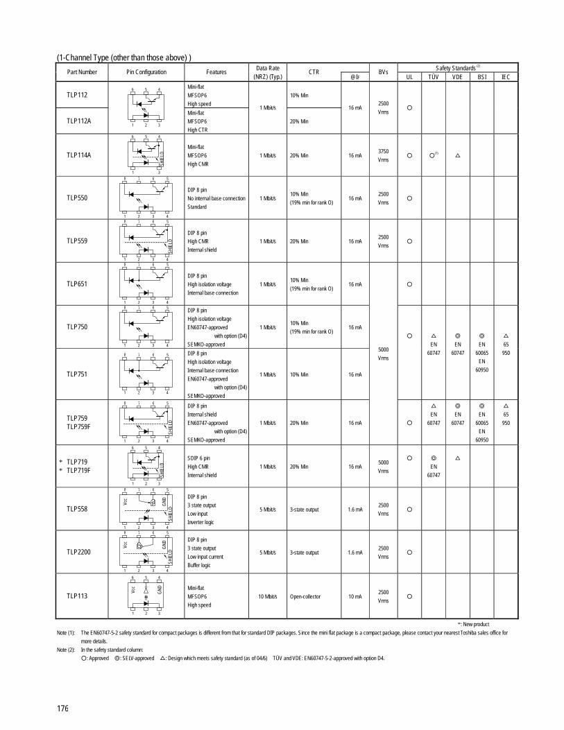
176
(1-Channel Type (other than those above) ) Safety Standards (2)
Part Number Pin Configuration Features Data Rate
(NRZ) (Typ.) CTR
@IF BVs
UL TÜV VDE BSI IEC
TLP112 Mini-flat
MFSOP6
High speed
10% Min
TLP112A
1 3
4 6 5
2
Mini-flat
MFSOP6
High CTR
1 Mbit/s
20% Min
16 mA 2500
Vrms
TLP114A
1 3
4 6 5
SHIE
LD
Mini-flat
MFSOP6
High CMR
1 Mbit/s 20% Min 16 mA 3750
Vrms
(1)
TLP550
1 2
78
3 4
56
DIP 8 pin
No internal base connection
Standard
1 Mbit/s 10% Min
(19% min for rank O) 16 mA
2500
Vrms
TLP559
1 2
7 8
3 4
5 6
SHIE
LD
DIP 8 pin
High CMR
Internal shield
1 Mbit/s 20% Min 16 mA 2500
Vrms
TLP651
1 2
78
3 4
56
DIP 8 pin
High isolation voltage
Internal base connection
1 Mbit/s 10% Min
(19% min for rank O) 16 mA
TLP750
1 2
78
3 4
56
DIP 8 pin
High isolation voltage
EN60747-approved
with option (D4)
SEMKO-approved
1 Mbit/s 10% Min
(19% min for rank O) 16 mA
TLP751
1 2
78
3 4
56
DIP 8 pin
High isolation voltage
Internal base connection
EN60747-approved
with option (D4)
SEMKO-approved
1 Mbit/s 10% Min 16 mA
EN
60747
EN
60747
EN
60065
EN
60950
65
950
TLP759 TLP759F
1 2
7 8
3 4
5 6
SHIE
LD
DIP 8 pin
Internal shield
EN60747-approved
with option (D4)
SEMKO-approved
1 Mbit/s 20% Min 16 mA
5000
Vrms
EN
60747
EN
60747
EN
60065
EN
60950
65
950
* TLP719 * TLP719F
1 3
4 6 5
SHIE
LD
2
SDIP 6 pin
High CMR
Internal shield
1 Mbit/s 20% Min 16 mA 5000
Vrms
EN
60747
TLP558
Vcc
GND
1 2
7 8
3 4
5 6
SHIE
LD
DIP 8 pin
3 state output
Low input
Inverter logic
5 Mbit/s 3-state output 1.6 mA 2500
Vrms
TLP2200
Vcc
GND
1 2
7 8
3 4
5 6
SHIE
LD
DIP 8 pin
3 state output
Low input current
Buffer logic
5 Mbit/s 3-state output 1.6 mA 2500
Vrms
TLP113
1 3
4 6 5
Vcc
GND
2
Mini-flat
MFSOP6
High speed
10 Mbit/s Open-collector 10 mA 2500
Vrms
*: New product
Note (1): The EN60747-5-2 safety standard for compact packages is different from that for standard DIP packages. Since the mini flat package is a compact package, please contact your nearest Toshiba sales office for
more details.
Note (2): In the safety standard column:
: Approved : SELV-approved : Design which meets safety standard (as of 04/6) TÜV and VDE: EN60747-5-2-approved with option D4.

177
Safety Standards (2)
Part Number Pin Configuration Features Data Rate
(NRZ) (Typ.) CTR
@IF BVs
UL TÜV VDE BSI IEC
TLP115 Mini-flat
MFSOP6
High CMR
10 mA
TLP115A
1 3
4 6 5
SHIE
LD Vc
c
GND
2
Mini-flat
MFSOP6
High CMR
Low input current
10 Mbit/s Open-collector
5 mA
2500
Vrms
TLP552
Vcc
GND
1 2
78
3 4
56
DIP 8 pin
High speed
Logic output
10 Mbit/s Open-collector 5 mA 2500
Vrms
TLP2601
Vcc
GND
1 2
7 8
3 4
5 6
SHIE
LD
DIP 8 pin
High CMR
High speed
10 Mbit/s Open-collector 5 mA 2500
Vrms
Note (2): In the safety standard column:
: Approved : SELV-approved : Design which meets safety standard (as of 04/6) TÜV and VDE: EN60747-5-2-approved with option D4.
(2-Channel Type) Safety Standards (2)
Part Number Pin Configuration Features Data Rate
(NRZ) (Typ.) CTR
@IF BVs
UL TÜV VDE BSI IEC
TLP2530 Dual-channel version of the
6N135 1 Mbit/s 7% Min 16 mA
TLP2531
1 2
7 8
3 4
5 6
Dual-channel version of the
6N136 1 Mbit/s 19% Min 16 mA
TLP2630
Vcc
GND
1 2
78
3 4
56
Dual-channel version of the
6N137 10 Mbit/s Open-collector 5 mA
TLP2631
Vcc
GND
SHIE
LD
1 2
7 8
3 4
5 6
High CMR
Dual-channel version of the
TLP2601
10 Mbit/s Open-collector 5 mA
2500
Vrms
Note (2): In the safety standard column:
: Approved : SELV-approved : Design which meets safety standard (as of 04/6) TÜV and VDE: EN60747-5-2-approved with option D4.
(JEDEC Type) Safety Standards (2)
Part Number Pin Configuration Features Data Rate
(NRZ) (Typ.) CTR
@IF BVs
UL TÜV VDE BSI IEC
6N135 7% Min
6N136 1 2
78
3 4
56
JEDEC type
Standard 1 Mbit/s
19% Min
16 mA
6N137
Vcc
GND
1 2
78
3 4
56
JEDEC type
High speed 10 Mbit/s 700% Typ. 5 mA
6N138 300% Min 1.6 mA
6N139
1 2
78
3 4
56
JEDEC type
High CTR 300 kbit/s
400% Min 0.5 mA
2500
Vrms
Note (2): In the safety standard column:
: Approved : SELV-approved : Design which meets safety standard (as of 04/6) TÜV and VDE: EN60747-5-2-approved with option D4.

178
Photovoltaic Output Devices Short−Circuit Current (µA) Open Voltage Voc (V) Safety Standards (2)
Part Number Pin Configuration Features Rank Min @IF Min @IF
BVs UL TÜV VDE BSI IEC
TLP190B
1 3
46
Mini-flat
MFSOP6 ⎯ 12 10 mA 7 10 mA
TLP191B
1 3
46
Mini-flat
MFSOP6
Internal shunt resistor
⎯ 24 20 mA 7 20 mA
⎯ 12
TLP590B
1 3
46
2
DIP 6 pin
General-purpose C20 20
10 mA 7 10 mA
⎯ 24
TLP591B
1 3
46
2
DIP 6 pin
Internal shunt resistor C40 40
20 mA 7 20 mA
2500
Vrms
Note (2): In the safety standard column:
: Approved : SELV-approved : Design which meets safety standard (as of 04/6) TÜV and VDE: EN60747-5-2-approved with option D4.

179
Photo Relays (MOSFET Output Devices, 1-Form-A) Safety Standards (2)
Part Number Pin Configuration Features VOFF min (V)
ION max (A)
RON max (Ω)
RON typ. (Ω)
Coff typ. (pF)
IFT max (mA)
BVs (min)
(Vrms) UL TÜV VDE BSI IEC
TLP3130 2.54SOP4
Lower CR
For testers
0.16 8 5 1 4
TLP3230 SSOP4
Lower CR
For testers
0.16 8 5 1 4
TLP3131 2.54SOP4
Lower CR
For testers
0.3 1.5 1 5 4
TLP3231
1 2
3 4
SSOP4
Lower CR
For testers
20
0.45 1.2 0.8 5 4
TLP3113 2.54SOP4
Lower CR
For testers
0.08 35 25 0.6 4
TLP3213 SSOP4
Lower CR
For testers
0.08 35 25 0.6 4
TLP3116 2.54SOP4
Lower CR
For testers
0.12 15 10 1 4
TLP3216 SSOP4
Lower CR
For testers
0.12 15 10 1 4
TLP3114 2.54SOP4
Lower CR
For testers
0.25 3 2 5 4
TLP3214 SSOP4
Lower CR
For testers
0.25 3 2 5 4
TLP3115 2.54SOP4
Lower CR
For testers
0.3 1.5 1 10 4
TLP3215
1 2
3 4
SSOP4
Lower CR
For testers
40
0.3 1.5 1 10 4
1500
TLP3110
1 3
46
MFSOP6 (4-pin)
Lower CR
For testers
0.35 1.2 0.9 100 4
TLP172A 2.54 SOP4
Economical
High output current
0.4 2 1 130 3
TLP176A 1 2
34
2.54 SOP4
High output current 0.4 2 1 130 3
TLP192A 2.54 SOP6
Economical
High output current
0.4 2 1 130 3
TLP197A
1 3
4 5 6
2
2.54 SOP6
High output current 0.4 2 1 130 3
1500
TLP225A
1 2
34
DIP4
For DC use only 0.5 1.1 0.8 ⎯ 5
TLP222A DIP4
Economical
High output current
0.5 2 1 130 3
TLP227A 1 2
34
DIP4
High output current
60
0.5 2 1 130 3
2500
Note (2): In the safety standard column: : Approved : SELV-approved : Design which meets safety standard (as of 04/6) TÜV and VDE: EN60747-5-2-approved with option D4.

180
Photo Relays (MOSFET Output Devices, 1-Form-A) (continued) Safety Standards (2)
Part Number Pin Configuration Features VOFF min (V)
ION max (A)
RON max (Ω)
RON typ. (Ω)
Coff typ. (pF)
IFT max (mA)
BVs (min)
(Vrms) UL TÜV VDE BSI IEC
TLP592A DIP6
Economical
High output current
0.5 2 1 130 3
TLP597A
1 3
4 5 6
2
DIP6
High output current 0.5 2 1 130 3
2500
TLP3540
8 7 6 5
1 2 3 4
DIP8
High output current 2.0 0.12 ⎯ 600 5 1500
TLP3542
1 3
456
2
DIP6
High output current
60
2.5 0.1 0.065 400 3 2500
TLP3111
1 3
46
MFSOP6 (4-pin)
Lower CR
For testers
0.1 20 16 11 4
TLP3217 SSOP4
For testers 0.12 12 8 5 5
TLP3121
1 2
3 4
2.54SOP4
Lower CR
For testers
0.35 1.2 1 30 4
TLP3120
1 3
456
2
2.54SOP6
High output current
80
1.25 0.15 0.11 460 5
1500
TLP179D
1 2
34
2.54SOP4
Lower CR
For testers
0.05 50 40 15 3
TLP199D
1 3
4 5 6
2
2.54SOP6
Lower CR
For testers
0.05 50 40 15 3
TLP176D
1 2
34
2.54 SOP4
For PBXes, telecom 0.2 8 5 100 3
TLP197D
1 3
4 5 6
2
2.54 SOP6
General-purpose
200
0.2 8 5 100 3
1500
TLP172G
1 2
34
2.54 SOP4
Economical
General-purpose
0.11 35 25 30 3
TLP192G
1 3
4 5 6
2
2.54 SOP6
Economical
General-purpose
0.11 35 25 30 3
TLP176G
1 2
34
2.54 SOP4
General-purpose
350
0.12 35 15 40 3
1500
Note (2): In the safety standard column: : Approved : SELV-approved : Design which meets safety standard (as of 04/6) TÜV and VDE: EN60747-5-2-approved with option D4.

181
Safety Standards (2)
Part Number Pin Configuration Features VOFF min (V)
ION max (A)
RON max (Ω)
RON typ. (Ω)
Coff typ. (pF)
IFT max (mA)
BVs (min)
(Vrms) UL TÜV VDE BSI IEC
TLP197G
1 3
4 5 6
2
2.54 SOP6
General-purpose 0.12 35 15 40 3
TLP174G
1 2
34
2.54 SOP4
Current-limiting function
General-purpose,
For modems
0.12 35 15 40 3
1500
TLP222G
DIP4
Economical
General-purpose,
For modems
0.12 35 25 30 3
TLP227G 1 2
34
DIP4
General-purpose,
For modems
0.12 35 15 40 3
TLP592G DIP6
Economical
General-purpose
0.12 35 25 30 3
TLP597G 1 3
456
2
DIP6
General-purpose 0.12 35 15 40 3
TLP224G
1 2
34
DIP4
Current-limiting function
For modems
0.12 35 15 40 3
TLP594G
1 3
4 5 6
2
DIP6
Current-limiting function
General-purpose
350
0.12 35 15 40 3
2500
TLP176GA 2.54 SOP4
General-purpose,
For modems
0.12 35 17 70 3
TLP174GA 1 2
34
2.54 SOP4
Current-limiting function
General-purpose,
For modems
0.12 35 17 70 3
TLP197GA
1 3
4 5 6
2
2.54 SOP6
Current-limiting function
General-purpose
0.12 35 17 70 3
TLP3125
8 7 6 5
1 2 3 4
2.54 SOP8 0.2 4 3.5 410 3
1500
TLP227GA DIP4
General-purpose,
For modems
0.12 35 17 70 3
TLP224GA 1 2
34
DIP4
Current-limiting function
For modems
400
0.12 35 17 70 3
2500
TLP597GA DIP6,
General-purpose 0.12 35 17 70 3 2500
TLP797GA DIP6
High isolation voltage
400 0.12 35 17 70 3
TLP797J 1 3
456
2 DIP6
High isolation voltage 600 0.1 35 25 120 3
5000
Note (2): In the safety standard column: : Approved : SELV-approved : Design which meets safety standard (as of 04/6) TÜV and VDE: EN60747-5-2-approved with option D4.

182
Photo Relays (MOSFET Output Devices, 2-Form-A) Safety Standards (2)
Part Number Pin Configuration Features VOFF min (V)
ION max (A)
RON max (Ω)
RON typ. (Ω)
Coff typ. (pF)
IFT max (mA)
BVs (min)
(Vrms) UL TÜV VDE BSI IEC
TLP202A 2.54 SOP8,
Two TLP172A channels 0.4 2 1 130 3
TLP206A 1 2
78
3 4
56
2.54 SOP8,
Two TLP176A channels 0.4 2 1 130 3
1500
TLP222A-2 DIP8
Two TLP222A channels 0.5 2 1 130 3
TLP227A-2 1 2
78
3 4
56
DIP8
Two TLP227A channels
60
0.5 2 1 130 3 2500
TLP209D 2.54 SOP8,
Two TLP179D channels 0.05 50 40 15 3
TLP200D 2.54 SOP8,
Two TLP176D channels
200 0.2 8 5 100 3
TLP202G 2.54 SOP8,
Two TLP172G channels 0.11 35 25 30 3
TLP206G 2.54 SOP8,
Two TLP176G channels 0.12 35 17 40 3
TLP204G
1 2
78
3 4
56
2.54 SOP8,
Two TLP174G channels 0.12 35 17 40 3
1500
TLP222G-2 DIP8, Two TLP222G channels 0.12 50 25 30 3
TLP227G-2 DIP8, Two TLP227G channels 0.12 35 15 40 3
TLP224G-2 1 2
78
3 4
56
DIP8, Two TLP224G channels
350
0.12 35 15 40 3
2500
TLP206GA 2.54 SOP8,
Two TLP176GA channels 0.12 35 17 70 3
TLP204GA 1 2
78
3 4
56
2.54 SOP8,
Two TLP174GA channels 0.12 35 17 70 3
1500
TLP227GA-2 DIP8,
Two TLP227GA channels 0.12 35 17 70 3
TLP224GA-2 1 2
78
3 4
56
DIP8,
Two TLP224GA channels
400
0.12 35 17 70 3 2500
Note (2): In the safety standard column: : Approved : SELV-approved : Design which meets safety standard (as of 04/6) TÜV and VDE: EN60747-5-2-approved with option D4.

183
Photo Relays (MOSFET Output Devices, 1-Form-B) Safety Standards (2)
Part Number Pin Configuration Features VOFF min (V)
ION max (A)
RON max (Ω)
RON typ. (Ω)
Coff typ. (pF)
IFT max (mA)
BVs (min)
(Vrms) UL TÜV VDE BSI IEC
TLP4172G
1 2
3 4
2.54SOP4
General-purpose 0.09 50 25 30 3
TLP4192G
1 3
4 5 6
2
2.54SOP6
General-purpose 0.09 50 25 30 3
1500
TLP4222G
1 2
3 4
DIP4
General-purpose 0.1 50 25 30 3
TLP4592G
1 3
4 5 6
2
DIP6
General-purpose 0.1 50 25 30 3
2500
TLP4176G
1 2
3 4
2.54SOP4
General-purpose 0.12 25 15 100 3
TLP4197G
1 3
4 5 6
2
2.54SOP6
General-purpose 0.12 25 15 100 3
1500
TLP4227G
1 2
3 4
DIP4
General-purpose 0.15 25 15 100 3
TLP4597G
1 3
4 5 6
2
DIP6
General-purpose
350
0.15 25 15 100 3
2500
Note (2): In the safety standard column: : Approved : SELV-approved : Design which meets safety standard (as of 04/6) TÜV and VDE: EN60747-5-2-approved with option D4.
Photo Relays (MOSFET Output Devices, 2-Form-B) Safety Standards (2)
Part Number Pin Configuration Features VOFF min (V)
ION max (A)
RON max (Ω)
RON typ. (Ω)
Coff typ. (pF)
IFT max (mA)
BVs (min)
(Vrms) UL TÜV VDE BSI IEC
TLP4202G 2.54SOP8,
Two TLP4172G channels 0.09 50 25 30 3 1500
TLP4222G-2 DIP8,
Two TLP4222G channels 0.1 50 25 30 3 2500
TLP4206G 2.54SOP8,
Two TLP4176G channels 0.12 25 15 100 3 1500
TLP4227G-2
1 2
7 8
3 4
56
DIP8,
Two TLP4227G channels
350
0.15 25 15 100 3 2500
Note (2): In the safety standard column: : Approved : SELV-approved : Design which meets safety standard (as of 04/6) TÜV and VDE: EN60747-5-2-approved with option D4.

184
Photo Relays (MOSFET Output Devices, 1-Form-B + 1-Form-A) Safety Standards (2)
Part Number Pin Configuration Features VOFF min (V)
ION max (A)
RON max (Ω)
RON typ. (Ω)
Coff typ. (pF)
IFT max (mA)
BVs (min)
(Vrms) UL TÜV VDE BSI IEC
TLP4027G 2.54SOP8
1a1b (N.C. + N.O.)
General-purpose
0.09 50 25 30 3 1500
TLP4007G DIP8
1a1b (N.C. + N.O.)
General-purpose
0.1 50 25 30 3 2500
TLP4026G 2.54SOP8
1a1b (N.C. + N.O.)
General-purpose
0.12 25 15 65 3 1500
TLP4006G
1 2
7 8
3 4
56
1-form-b 1-form-a
DIP8
1a1b (N.C. + N.O.)
General-purpose
350
0.12 25 15 65 3 2500
Note (2): In the safety standard column: : Approved : SELV-approved : Design which meets safety standard (as of 04/6) TÜV and VDE: EN60747-5-2-approved with option D4.

185
Products Manufactured by Toshiba Semiconductor (Thailand) Co., Ltd.
Part Number Pin Configuration Features VCEO Safety Standards (2)
BVs
UL TÜV VDE BSI IEC
TLP180(T)
1
46
3
Mini-flat
MFSOP6
AC input
SEMKO-approved
80 V 3750
Vrms
(1)
EN
60950
950
TLP181(T)
1
46
3
Mini-flat
MFSOP6
SEMKO-approved
General-purpose
80 V 3750
Vrms
(1)
EN
60950
950
TLP521-1(T)
1
34
2
DIP 4 pin
General-purpose
TLP521-2(T)
1
78
2 3
56
4
2 channels of the TLP521-1(T)
55 V 2500
Vrms
TLP620(T)
1
34
2
DIP 4 pin
AC input
SEMKO-approved
EN
60747
EN
60747
EN
60065
EN
60950
TLP620-2(T)
1
78
2 3
56
4
2 channels of the TLP620(T)
SEMKO-approved
55 V 5000
Vrms
EN
60747
EN
60747
EN
60065
EN
60950
65
950
TLP621(T)
1
34
2
DIP 4 pin
High isolation voltage
SEMKO-approved
EN
60747
EN
60747
EN
60065
EN
60950
TLP621-2(T)
1
78
2 3
56
4
2 channels of the TLP621(T)
SEMKO-approved
55 V 5000
Vrms
EN
60747
EN
60747
EN
60065
EN
60950
65
950
TLP627(T)
1 2
34
DIP 4 pin
Darlington transistor output
High VCEO
SEMKO-approved
EN
60747
EN
60747
EN
60065
EN
60950
TLP627-2(T)
2
8
3
567
1 4
2 channels of the TLP627(T)
SEMKO-approved
300 V 5000
Vrms
EN
60747
EN
60747
EN
60065
EN
60950
65
950
Note (1): The EN60747-5-2 safety standard for compact packages is different from that for standard DIP packages. Since the mini flat package is a compact package, please contact your nearest Toshiba sales office for
more details.
Note (2): In the safety standard column:
: Approved : SELV-approved : Design which meets safety standard (as of 04/6) TÜV and VDE: EN60747-5-2-approved with option D4.
Note that the products manufactured by Toshiba Semiconductor (Thailand) Co., Ltd. are not available in Japan.

186
Fiber-Optic Devices (TOSLINKTM)
Fiber-Optic Modules (Simplex type)
Fiber-Optic Transmitting Module
Fiber-Optic Receiving Module
Data Rate (b/s, NRZ)
Transmission Distance (m)(1) max
Emission Wavelength
(nm)(1)
Pulse Width Distortion
(ns)(1)
Operating Temperature
(°C)
Compatible Optical Fiber (µm)
Compatible Optical Fiber with Fiber-Optic Connectors
1000 TOTX170(3) TORX170 DC to 6M 800
800 ±55 −40 to 70 H-PCF(200/230) CF-1001 Series (5)
TOTX170A(3) TORX170 DC to 6M 40 650 ±55 −40 to 70 APF(980/1000) LUCT1-TC1000-xxM (15) TOCP100-xxBT (16)
TOTX178A(9) TORX178B(9) 0.1 to 6M 5 650 ±30 −20 to 70 APF(970/1000)
APF(980/1000)
TOTX178S TORX178S 0.1 to 6M 5 650 ±30 −20 to 70
TOTX179(9) TORX179 (9) 0.1 to 12.8M 5 650 ±25 −20 to 70
APF(970/1000)
APF(980/1000)
TOTX179P TORX179P 0.1 to 12.8M 5 650 ±25 −20 to 70
TOTX179L(9)(13) TORX179L(9)(13) 0.1 to 12.8M 5 650 ±25 −20 to 70
TOTX179PL(13) TORX179PL(13) 0.1 to 12.8M 5 650 ±25 −20 to 70
TOTX179S TORX179S 0.1 to 12.8M 5 650 ±25 −20 to 70
TOTX140(4) (9) TORX178B 0.1 to 6M 5 660 ±30 −20 to 70
TOTX141(4) (9) TORX141(4) 0.1 to 15M 10 650 ±20 −20 to 70
TOTX141P(4) TORX141P(4) 0.1 to 15M 10 650 ±20 −20 to 70
TOTX141L(4)(9)(13) TORX141L(4)(9)(13) 0.1 to 15M 10 650 ±20 −20 to 70
TOTX141PL(4)(13) TORX141PL(4)(13) 0.1 to 15M 10 650 ±20 −20 to 70
APF(970/1000)
APF(980/1000)
LUCT1-TC1000-xxM (15) TOCP100-xxBT (16)
1000 TOTX180(3)(11) TORX180(11) DC to 6M
800 800 ±55 −40 to 85 H-PCF(200/230) CF-1001 Series (5)
1000 TOTX180(11) TORX186(11) DC to 8M
800 800 ±42 −40 to 85 H-PCF(200/230) CF-1001 Series (5)
TOTX180A(3)(11) TORX180(11) DC to 6M 40 650 ±55 −40 to 85 APF(980/1000) LUCT1-TC1000-xxM (15) TOCP100-xxBT (16)
TOTX193 TORX193 DC to 6M 10 660 ±25 −40 to 85
TOTX193K(9) TORX193K(9) DC to 6M 10 660 ±25 −40 to 85 APF(980/1000) ⎯
1000 TOTX194(3) TORX194 DC to 10M
700 800 ±30 −40 to 85 H-PCF(200/230) CF-1001 Series (5)
TOTX195(3) TORX194 DC to 10M 50 670 ±30 −40 to 85 APF(980/1000) LUCT1-TC1000-xxM (15) TOCP100-xxBT (16)
1000 TOTX196 TORX196 DC to 6M
800 800 ±55 −40 to 85 H-PCF(200/230) CF-1001 Series (5)
1000 TOTX196 TORX198(2) DC to 6M
800 800 ±55 −40 to 85 H-PCF(200/230) CF-1001 Series (5)
TOTX197 TORX196 DC to 6M 40 670 ±55 −40 to 85 APF(980/1000) LUCT1-TC1000-xxM (15) TOCP100-xxBT (16)
TOTX197 TORX198(2) DC to 6M 40 670 ±55 −40 to 85 APF(980/1000) LUCT1-TC1000-xxM (15) TOCP100-xxBT (16)
TOSLINK is a trademark of Toshiba Corporation.
The part number of the lead-free package is suffixed with (F). For details, please consult Toshiba sales office. Note (1): Indicates values when Ta = 25°C Note (2): These fiber-optic receiving modules have analog output pins for monitoring the amount of received light. Note (3): External resistances must be changed according to the transmission distance. Note (4): VCC = 2.7 V to 3.6 V Note (5): Manufactured by Sumitomo Electric Industries, Ltd. Note (9): These are panel mount type fiber-optic modules. Note (11): These are fiber-optic modules in a ceramic package. Note (12): Under development Note (13): Shutter system. Note (14): Manufactured by TST (Toshiba Semiconductor (Thailand) Co., Ltd.). Note (15): Manufactured by Asahi Kasei EMD Corporation. Note (16): Manufactured by Toray Industries, inc. Note (17): Manufactured by Mitsubishi Rayon Co., Ltd.

187
Fiber-Optic Transmitting Module
Data Rate (NRZ, b/s)
Emission Wavelength
(nm)
Fiber Output Power (dBm)(1)
PulseWidth Distortion
(nm)(1)
Supply Voltage (V)
Operating Temperature
(°C)
Compatible Optical Fiber (µm)
Compatible Optical Fiber with Connectors
TOTX141(F,T)(9)(14) DC to 15 M 650 −21 to −15 ±20 2.7 to 3.6 −20 to 70
TOTX141P(F,T) DC to 15 M 650 −21 to −15 ±20 2.7 to 3.6 −20 to 70
TOTX147(F,T)(9)(14) DC to 15M 650 −21 to −15 ±15 2.7 to 3.6 −20 to 70
TOTX147L(F,T)(9)(13)(14) DC to 15M 650 −21 to −15 ±15 2.7 to 3.6 −20 to 70
TOTX147PL(F,T) DC to 15M 650 −21 to −15 ±15 2.7 to 3.6 −20 to 70
TOTX177(F,T)(9)(14) DC to 15M 650 −21 to −15 ±15 5 ± 0.25 −20 to 70
TOTX177L(F,T)(9)(13)(14) DC to 15M 650 −21 to −15 ±15 5 ± 0.25 −20 to 70
TOTX177PL(F,T) DC to 15M 650 −21 to −15 ±15 5 ± 0.25 −20 to 70
TOTX178A(F,T)(9)(14) DC to 6M 650 −21 to −15 ±30 5 ± 0.25 −20 to 70
TOTX178S(F,T) DC to 6M 650 −21 to −15 ±30 5 ± 0.25 −20 to 70
TOTX179(F,T)(9)(14) DC to 12.8M 650 −21 to −15 ±25 5 ± 0.25 −20 to 70
TOTX179P(F,T) DC to 12.8M 650 −21 to −15 ±25 5 ± 0.25 −20 to 70
TOTX179S(F,T) DC to 12.8M 650 −21 to −15 ±25 5 ± 0.25 −20 to 70
APF(980/1000) RFA4011-*** (17)
Fiber-Optic Receiving Module
Data Rate (NRZ, b/s)
Maxmum Receivable Power
(dBm)(1)
Minimum Receivable Power
(dBm)(1)
PulseWidth Distortion
(nm)(1)
Supply Voltage (V)
Operating Temperature
(°C)
Compatible Optical Fiber (µm)
Compatible Optical Fiber with Connectors
TORX147(F,T)(9)(14) 0.1 to 15M −14.5 −24 ±15 2.7 to 3.6 −20 to 70
TORX147L(F,T)(9)(13)(14) 0.1 to 15M −14.5 −24 ±15 2.7 to 3.6 −20 to 70
TORX147PL(F,T) 0.1 to 15M −14.5 −24 ±15 2.7 to 3.6 −20 to 70
TORX177(F,T)(9)(14) 0.1 to 15M −14.5 −24 ±15 5 ± 0.25 −20 to 70
TORX177L(F,T)(9)(13)(14) 0.1 to 15M −14.5 −24 ±15 5 ± 0.25 −20 to 70
TORX177PL(F,T) 0.1 to 15M −14.5 −24 ±15 5 ± 0.25 −20 to 70
APF(980/1000) RFA4011-*** (17)
TOSLINK is a trademark of Toshiba Corporation.
The part number of the lead-free package is suffixed with (F). For details, please consult Toshiba sales office.
Note (1): Indicates values when Ta = 25°C Note (2): These fiber-optic receiving modules have analog output pins for monitoring the amount of received light. Note (3): External resistances must be changed according to the transmission distance. Note (4): VCC = 2.7 V to 3.6 V Note (5): Manufactured by Sumitomo Electric Industries, Ltd. Note (9): These are panel mount type fiber-optic modules. Note (11): These are fiber-optic modules in a ceramic package. Note (12): Under development Note (13): Shutter system. Note (14): Manufactured by TST (Toshiba Semiconductor (Thailand) Co., Ltd.). Note (15): Manufactured by Asahi Kasei EMD Corporation. Note (16): Manufactured by Toray Industries, inc. Note (17): Manufactured by Mitsubishi Rayon Co., Ltd.

188
Fiber-Optic Modules (Duplex type)
Fiber-Optic Transceiving Module
Data Transmission Rate
(b/s, NRZ)
Transmission Distance (m)(1) max
Emission Wavelength
(nm)(1)
Pulse Width Distortion
(ns)(1)
Operating Temperature
(°C)
Compatible Optical Fiber (µm)
Compatible Optical Fiber with Fiber-Optic Connectors
1000 TODX270(3) DC to 6M 800
800 ±55 −40 to 70 H-PCF(200/230) CF-2001/2071 Series (5)
TODX270A(3) DC to 6M 40 650 ±55 −40 to 70 APF(980/1000) LUCT2-1000W-xxM (15) TOCP200-xxBT (16)
1000 TODX280(3)(11) DC to 6M
800 800 ±55 −40 to 85 H-PCF(200/230) CF-2001/2071 Series (5)
TODX280A(3)(11) DC to 6M 40 650 ±55 −40 to 85 APF(980/1000) LUCT2-1000W-xxM (15) TOCP200-xxBT (16)
1000 TODX286(11) DC to 8M
800 800 ±42 −40 to 85 H-PCF(200/230) CF-2001/2071 Series (5)
APF(980/1000) LUCT2-1000W-xxM (15) TOCP200-xxBT (16) TODX283(11) DC to 50M
10(APF)
100(PCF) 650 ±7 −10 to 70
H-PCF(200/230) CF-2001/2071 Series (5) 1000
TODX294(3) DC to 10M 700
800 ±30 −40 to 85 H-PCF(200/230) CF-2001/2071 Series (5)
TODX295(3) DC to 10M 50 670 ±30 −40 to 85 APF(980/1000) LUCT2-1000W-xxM (15) TOCP200-xxBT (16)
1000 TODX296 DC to 6M
800 800 ±55 −40 to 85 H-PCF(200/230) CF-2001/2071 Series (5)
TODX297 DC to 6M 40 670 ±55 −40 to 85 APF(980/1000) LUCT2-1000W-xxM (15) TOCP200-xxBT (16)
1000 TODX298(2) DC to 8M
700 800 ±42 −40 to 85 H-PCF(200/230) CF-2001/2071 Series (5)
20 to 250M 20 m (250M) 0 to 60 (250M) TODX2402(12)
20 to 125M 50 m (125M) 650 ⎯
−10 to 70 (125M) APF(980/1000) RFA4412M-xxx (17)
Note (1): Indicates values when Ta = 25°C
Note (2): These fiber-optic receiving modules have analog output pins for monitoring the amount of received light.
Note (3): External resistances must be changed according to the transmission distance.
Note (5): Manufactured by Sumitomo Electric Industries, Ltd.
Note (11): These are fiber-optic modules in a ceramic package.
Note (12): New product
Note (15): Manufactured by Asahi Kasei EMD Corporation.
Note (16): Manufactured by Toray Industries, inc.
Note (17): Manufactured by Mitsubishi Rayon Co., Ltd.

189
SFF/SFP Optical Transceiver (SFF Optical Transciver)
Type Name Data Rate
(Gb/s) Transmission Distance
(1)
Operating Temperature(2)
(°C) Supply Voltage
(V) Wavelength
(nm) Detector
TOTR210 Up to 2.5 300 m (2.125 Gb/s, 50/125 µm MMF)
550 m (1.25 Gb/s, 50/125 µm MMF) 0 to 70 3.3 850(VCSEL) PD
TOTR210-T(3) Up to 2.5 300 m (2.125 Gb/s, 50/125 µm MMF)
550 m (1.25 Gb/s, 50/125 µm MMF) 0 to 70 3.3 850(VCSEL) PD
TOTR310-F Up to 2.5 2 km / 15 km (SMF) 0 to 70 3.3 1310(FP-LD) PD
TOTR310-FT(3) Up to 2.5 2 km / 15 km (SMF) 0 to 70 3.3 1310(FP-LD) PD
TOTR310-D Up to 2.5 15 km (SMF) 0 to 70 3.3 1300(DFB × 4) PD
TOTR310-DAC(4) Up to 2.5 40 km (SMF) 0 to 70 3.3 1300(DFB × 4) APD
TOTR360-D Up to 2.5 15 km / 40 km (SMF) 0 to 70 3.3 1550(DFB × 8) PD
TOTR360-DAC(4) Up to 2.5 80 km (SMF) 0 to 70 3.3 1550(DFB × 8) APD
Note (1): Target distance.
Note (2): Case Temperature
Note (3): 2 × 5 pins package
Note (4): Integrated DC/DC Converter.
(SFP Optical Transceiver)
Type Name Data Rate
(Gb/s) Transmission Distance(1)
Operating Temperature(2)
(°C) Supply Voltage
(V) Wavelength
(nm) Detector
TOTR210P Up to 2.5 300 m (2.125 Gb/s, 50/125 µm MMF)
550 m (1.25 Gb/s, 50/125 µm MMF) 0 to 70 3.3 850(VCSEL) PD
TOTR310P-F Up to 2.5 2 km / 15 km (SMF) 0 to 70 3.3 1310(FP-LD) PD
TOTR310P-D Up to 2.5 15 km (SMF) 0 to 70 3.3 1300(DFB × 4) PD
TOTR310P-DA(4) Up to 2.5 40 km (SMF) 0 to 70 3.3 1300(DFB × 4) APD
TOTR360P-D Up to 2.5 15 km / 40 km (SMF) 0 to 70 3.3 1550(DFB × 8) PD
TOTR360P-DA(4) Up to 2.5 80 km (SMF) 0 to 70 3.3 1550(DFB × 8) APD
Note (1): Target distance.
Note (2): Case Temperature
Note (3): 2 × 5 pins package
Note (4): Integrated DC/DC Converter.
(SFP Optical Transceiver with Digital Diagnostic Capability and Pull de-latch Lever)
Type Name Data Rate
(Gb/s) Transmission Distance(1)
Operating Temperature(2)
(°C) Supply Voltage
(V) Wavelength
(nm) Detector
TOTR211P Up to 2.5 300 m (2.125 Gb/s, 50/125 µm MMF)
550 m (1.25 Gb/s, 50/125 µm MMF) 0 to 70 3.3 850(VCSEL) PD
TOTR311P-F Up to 2.5 2 km / 15 km (SMF) 0 to 70 3.3 1310(FP-LD) PD
TOTR311P-D Up to 2.5 15 km (SMF) −10 to 70 3.3 1300(DFB × 4) PD
TOTR311P-DA(4) Up to 2.5 40 km (SMF) −10 to 70 3.3 1300(DFB × 4) APD
TOTR361P-D Up to 2.5 15 km / 40 km (SMF) −10 to 70 3.3 1550(DFB × 8) PD
TOTR361P-DA(4) Up to 2.5 80 km (SMF) −10 to 70 3.3 1550(DFB × 8) APD
Note (1): Target distance.
Note (2): Case Temperature
Note (3): 2 × 5 pins package
Note (4): Integrated DC/DC Converter.

190
Image Sensors
CCD Linear Image Sensors Photo Sensitive Pixels (Picture Element)
Classification Part Number Type/Lamp Number Size (µm)
Sensitivity (Typ.) (V/lx · s)
Data Rate (MHz)
Other Features
TCD1706DG 7400 25×4
TCD1708DG 7450 4.7×4.7
15×2 Single 5-V power supply
TCD1709DG 7500 7×7 25×4
TCD1711DG
B/W
7450 4.7×4.7
15
30×2
TCD2558DG-1 5340×3 Line 7×7 R:8.5, G:12.7, B:9.5 10
TCD2561DG-1 5340×4 Line 7×7 R:10.4, G:14.4, B:8.7, B/W:21.0 Color:10, B/W:10×2
TCD2702ADG 7350×3 Line R:7.8, G:11.5, B:3.7 2-line interlace
TCD2703ADG 7500×3 Line 9.325×9.325
R:9.3, G:14.5, B:4.8 25×2
TCD2704DG-1 7500×4 Line 5×5 R:4.9, G:6.3, B:4.2, B/W:10.8 Color:12, B/W:12×2
TCD2705DG 7300×3 Line 10×10 R:3.6, G:4.7, B:2.7 30×2
TCD2707DG 7450×4 Line 4.7×4.7 R:5.5, G:8.5, B:4.2, B/W:12.8 Color:20, B/W:25×2
TCD2905CFG 5400×6 Line 5.25×5.25 R:4.7, G:6.4, B:3.7 10
TCD2908CFG 5400×8 Line 5.25×5.25 R:4.9, G:6.7, B:3.6, B/W:22.4 Color:10, B/W:10×2
TCD2953CFG 10680×6 Line 4 pitch R:1.5, G:2.0, B:1.4 10 Overflow drain, 4-µm pitch
TCD2955CFG 14240×6 Line 3×4 R:1.5, G:2.0, B:1.4 10 Overflow drain
Lens reduction
type
TCD2957CFG
Color
10680×6 Line 2.625×3.9 R:1.7, G:2.1, B:1.1 10 Electronic Shatter
CIPS54CS301 R, G, B 644 50×40 --- 2.5
CIPS317CF603 Color 7488×3 Color 23×34 --- 80/3 Color
CIPS308BS620A --- 90 Shading adjustment, 10-bit ADC
CIPS308BS621B YG 7296 24×40
--- 21 Shading adjustment, 8-bit ADC
CIS module
CIPS218CF601 R,G,B 5152 24×40 --- 5×2
Toshiba manufactures the products shown in bold in offshore factories.

191
Package
Resolution (DPI)
Uses Remark
22PIN Cerdip
68PIN Cerdip
22PIN Cerdip
A3 600 Photocopiers, Scanners
Color scanners
22PIN Cerdip A4 600
Photocopiers, Color scanners
68PIN Cerdip
MP: '05/2Q
22PIN Cerdip
68PIN Cerdip
22PIN Cerdip
A3 600 Photocopiers, Color scanners
22PIN CLCC A4 1200
A4 2400
32PIN CLCC
A4 3200
22PIN CLCC A4 2400
Color scanners
12PIN connector 54mm 300 Mobile ES: '03/3Q
40PIN connector Color scanners, MFP
24PIN connector,
8PIN connector ES: 3 months after order
35PIN connector
A3 600 Photocopiers, MFP
15PIN connector A4 600 MFP

192
Area Image Sensors and Signal Processors ICs Dynastron
Optical format Part number Total pixel number Color / Mono Package Power consumption Digital signal processor
1/4 inch TCM8210MD 698 × 502 (350K) Color (R, G, B) 24-pin package with optical
lens 100 mW (15 fps) Incorporated
1/6 inch TCM8230MD 698 × 502 (350K) Color (R, G, B) 20-pin package with optical
lens 30 mW (15 fps) Incorporated