onboard power supply management - volkspage.net · functions of onboard power supply control unit...
TRANSCRIPT
30
Functions of onboard power supply control unit
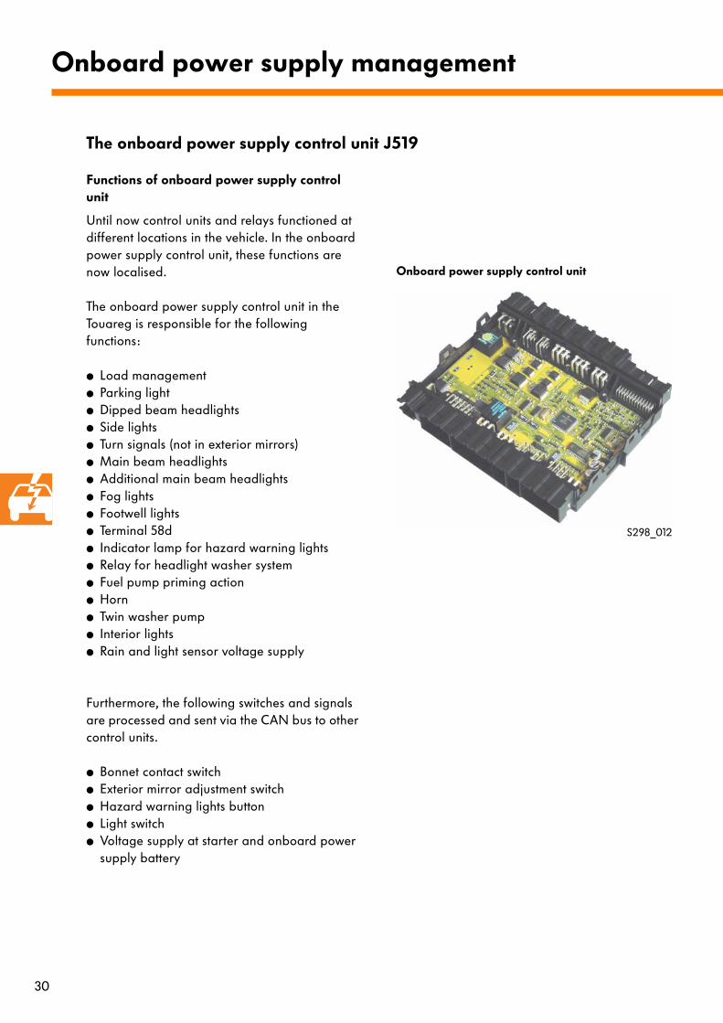
Until now control units and relays functioned at different locations in the vehicle. In the onboard power supply control unit, these functions are now localised.
The onboard power supply control unit in the Touareg is responsible for the following functions:
● Load management● Parking light● Dipped beam headlights● Side lights● Turn signals (not in exterior mirrors)● Main beam headlights● Additional main beam headlights● Fog lights● Footwell lights● Terminal 58d● Indicator lamp for hazard warning lights● Relay for headlight washer system● Fuel pump priming action● Horn● Twin washer pump● Interior lights● Rain and light sensor voltage supply
Furthermore, the following switches and signals are processed and sent via the CAN bus to other control units.
● Bonnet contact switch● Exterior mirror adjustment switch● Hazard warning lights button● Light switch● Voltage supply at starter and onboard power
supply battery
Onboard power supply management
S298_012
Onboard power supply control unit
The onboard power supply control unit J519

31
Fitting location of onboard power supply control unit and entry and start authorisation control unit
Fitting location
The onboard power supply control unit can be found in the vehicle interior on the driver's side under the dash panel in the footwell. It is connected to the E-box in the same way as the entry and start authorisation control unit.
S298_019
Entry and start authorisation control unit
Onboard power supply control unit
E-box under dash panel
Load management
Furthermore, the onboard power supply control unit deactivates convenience system consumers and long-term HT consumers e.g. heated rear windscreen, so that heavy discharging of the battery is avoided. If the onboard power supply is placed too much under load, the idling speed is also increased. This ensures that there is always sufficient energy to start the engine. Switching off is inline with the guidelines for the Volkswagen Phaeton and is described in Self-Study Programme 272.

32
Priming function of electrical fuel pump
The petrol engines of the Volkswagen Touareg all feature a priming function of the fuel pump so that enough pressure in the fuel lines can be built up.
Function:
When the driver's door is opened and terminal 15 is closed, a signal is sent via the CAN bus from the entry and start authorisation control unit J518 (terminal 15 off), a signal is also sent from the driver's door control unit J386 (driver's door opened) and, for reasons of safety, a discreet signal (status of terminal 15) is sent to the onboard power supply control unit J519. This then actuates the relay to prime the fuel pump for approx. 2 seconds. The priming function of the fuel pump is stopped when the ignition is switched on. Continued actuation is done through the engine control unit.
If the driver's door stays open, the actuation is repeated a maximum of three times in intervals.
Timed actuation from the onboard power supply control unit prevents continued actuation of the fuel pump if the driver's door is opened and closed a number of times in short intervals.
Crash shut-off
If with the ignition switched on a crash is detected, a signal is sent from the airbag control unit J234 via the CAN bus and the fuel pump is switched off immediately. After about 5 seconds it can be activated again by switching the ignition off and on.
Electric circuit
Onboard power supply management
S298_021
KeyG6 Fuel pumpJ17 Fuel pump relayJ386 Driver's door control unitJ518 Entry and start authorisation control unitJ519 Onboard power supply control unitJ623 Engine control unit
CAN bus
J518
J17
G6
J386
J519
J623
Discreet signal from terminal 15

33
Interior light actuation
The interior lighting is actuated by the onboard power supply control unit. The voltage supply comes from terminal 30G.
To prevent discharge of the vehicle battery when the interior lights are switched on, power supply from terminal 30G is interrupted in the following circumstances:
- the ignition is switched off,- the vehicle is locked from the outside and all
doors are locked.
Data transfer
J234
J285
W
F
J387 J388 J389 J519J386
Terminal 30G is activated under the following circumstances:
- the interior light switch is actuated,- the ignition is switched on,- the vehicle is unlocked, a door, the bonnet or
the tailgate is opened,- the bonnet contact switch.
S298_022
If a crash is detected, the interior light is switched on immediately. After the ignition is switched on and off and after is has been switched on again, the cut-off function from terminal 30G is reactivated.
KeyF Interior light switchJ234 Airbag control unitJ285 Dash panel insert (Gateway)J386 Driver door control unitJ387 Front passenger door control unitJ388 Rear left door control unitJ389 Rear right door control unitJ519 Onboard power supply control
unitW Interior lights

34
Key
A BatteryD Ignition switchE1 Light switchE3 Hazard warning light switchE20 Light regulator for lighting
switches and instrumentsE43 Exterior mirror adjustment switchE48 Mirror adjustment change-over switchE102 Headlight range control adjusterE231 Exterior mirror heating buttonE263 Mirror fold system switchE314 Rear fog light buttonE315 Fog light buttonE316 Glove box buttonE326 Interior light button, frontE457 Driver reading light buttonE458 Front passenger reading light buttonF120 Anti-theft alarm/
vermin repellent system contact switchF335 Stowage compartment illumination switchG213 Rain sensorH2 High tone hornH7 Low tone hornJ39 Relay for headlight washer systemJ144 Interior light switch-off delay blocking diode
Interior lightingM1 Side light bulb, leftM3 Side light bulb, rightM5 Turn signal bulb, front leftM7 Turn signal bulb, front rightM29 Dipped beam bulb, leftM30 Main beam bulb, leftM31 Dipped beam bulb, rightM32 Main beam bulb, rightU1 Cigarette lighterU9 Cigarette lighter, rear
Onboard power supply management
Signal output
GND
Signal output
Positive
CAN bus
The function layout

35
S298_013

36
Key
J285 Control unit with display indash panel insert
J400 Wiper motor control unitJ518 Entry and start authorisation control unit
Start authorisationJ519 Control unit for onboard power supplyJ533 Diagnosis interface for data busK6 Hazard warning light system warning lampL22 Foglight bulb, leftL23 Foglight bulb, rightL28 Cigarette lighter light bulbL42 Socket light bulbL67 Dash panel left vent illuminationL68 Dash panel central vent illuminationL69 Dash panel right vent illuminationL78 Mirror adjustment switch illuminationL87 Central rear vent illuminationL88 Rear left vent illuminationL89 Rear right vent illuminationL106 Footwell illumination, rear leftL107 Footwell illumination, rear rightL120 Shelf illuminationL151 Front left footwell illuminationL152 Front right footwell illuminationU19 12 V socket -3-U20 12 V socket -4-V11 Headlight washer system pumpV59 Windscreen and rear window washer pumpV Windscreen washer motorW1 Front interior lightW11 Reading lamp, rear leftW12 Reading lamp, rear rightW13 Front passenger reading lightW14 Illuminated vanity mirror
(front passenger side)W19 Reading lamp, driver sideW20 Illuminated vanity mirror
(driver side)Y7 Automatic anti-dazzle interior mirror
Onboard power supply management
The function layout
Signal output
GND
Signal output
Positive
CAN bus

37
S298_050

38
Headlights without additional main beamMain headlights
The basic equipment comprises a DE headlight with H7 halogen bulb and a H9 halogen bulb for main beam.
The ”M” equipment level features bi-xenon headlights for main and dipped beam and additional DE headlights with H7 bulbs for main beam. On this version, only the headlights for additional main beam flash when the flasher unit is actuated and the dipped beam is not switched on. A brief actuation of the xenon lamps, e.g. when flashing lights as a signal, shortens their useful life. The turn signals are cool blue in appearance but flash yellow when they are switched on.
Lighting
S298_029
S298_028
Dipped beam headlights
Main beam headlights
Turn signal light Side light
Headlight with additional main beam
The headlights
Additional main beam headlights
Dipped and main beam lights
Turn signal light
Side light
39
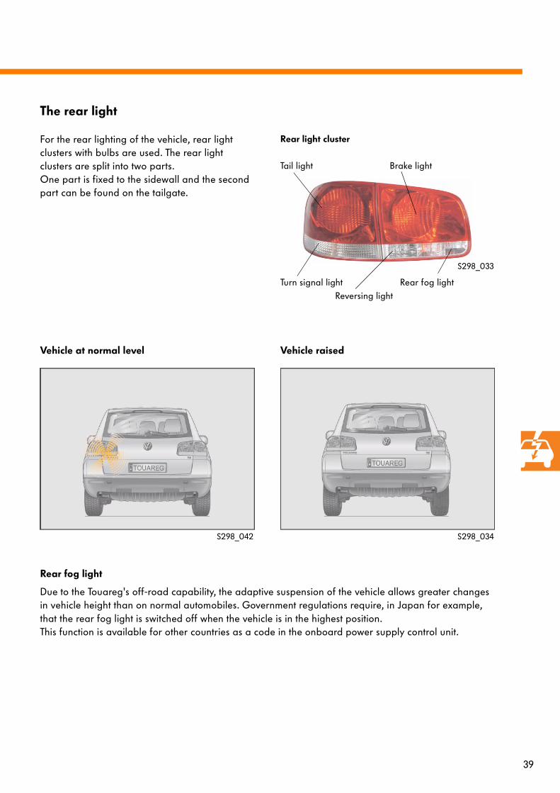
For the rear lighting of the vehicle, rear light clusters with bulbs are used. The rear light clusters are split into two parts.One part is fixed to the sidewall and the second part can be found on the tailgate.
Rear light cluster
Vehicle at normal level Vehicle raised
S298_034
Rear fog light
Due to the Touareg's off-road capability, the adaptive suspension of the vehicle allows greater changes in vehicle height than on normal automobiles. Government regulations require, in Japan for example, that the rear fog light is switched off when the vehicle is in the highest position. This function is available for other countries as a code in the onboard power supply control unit.
S298_042
The rear light
S298_033
Turn signal lightReversing light
Rear fog light
Tail light Brake light

40
Surround lighting
The lights integrated in the exterior mirrors illuminate the area around the vehicle.
Conditions for activation:
The lights are actuated simultaneously with:
- the interior lights,- the coming home/leaving home lighting
function.
Surround lights
The surround lights are controlled by the onboard power supply control unit via the CAN bus and actuated by the driver's and front passenger's door control units.
To prevent the surround lights from becoming damaged by long periods of activation, a protection feature is integrated in the onboard power supply control unit which switches off the lights after a prescribed duration to allow them to cool down.
Lighting
S298_023

41
Display in instrument panel insert
LIGHTFOOTWELL LIGHT
SETTING :
80 %
0.0 km 14 km
PR
DS
N
0:06
Lighting settings
In the set-up menu of the dash panel insert, various adjustments can be made to the lighting:
- Duration of coming-home lighting,- Day driving light,- Brightness of footwell lighting.
The duration of the coming-home lighting can be set between 0-90 seconds. After 90 seconds, the lights are switched off automatically to avoid discharging of the battery.
In the set-up menu, the day driving light function can be switched on or off. This option is only available in countries where day driving lights are not a legal requirement.
The footwell lighting can be adjusted from 0 %-100 %.
S298_031
S298_032
0.0 km 14 km
LIGHT
COMING HOMEDAY DRIVING
LIGHTFOOTWELL LIGHT
PR
DS
N
0:06
Display in instrument panel insert
The convenience lighting

42
Functions:
Turn signals
The main function of the turn signals is set in the onboard power supply control unit.
Signal sequence:
- Turn signal switch- Steering column electronics control unit- Onboard power supply control unit
(actuation of turn signals)- Trailer detection control unit
(actuation of turn signals on trailer)- Driver and front passenger door control units
(actuation of turn signals in exterior mirrors)- Dash panel insert
(actuation of warning lights and display of warning messages)
Side lights
The main function of the side lights is also set in the onboard power supply control unit.
Signal sequence:
- Light switch- Onboard power supply control unit
(actuation of front lights)- Convenience system central control unit
(actuation of rear lights)- Trailer detection control unit
(actuation of turn signals on trailer)- Dash panel insert
(actuation of warning lights and display of warning messages)
Networked functions
Fog lights
Side lights
Dipped beam headlightsMain beam headlights
Footwell lightingInterior lighting
Reversing light switch
Door handle lighting, interior
Door warning lamp
Door exit light
Surround lighting
Turn signal in exterior mirror
Footwell lighting
Light switch
Interior light switch
Switch for reading lights
Hazard warning light switch
Turn signal switch, rear
J388 / J389Door control unit, rear
J136 / J521Door control unit, front
J386 / J387Door control units, front
J519Onboard power supply control unit
J623 Engine control unit
Turn signal, front
Door handle lighting, interior
Door warning lamp
Door exit light
Door lock switch
The lighting
Door lock switch

43
Light sensor
Turn signal switchHeadlight dipper switchParking light switch
J285Dash panel insert (Gateway) Entry and start
authorisation aerials
J234Airbag control unit
J518 Entry and start authorisation control unit
J400 Wiper motor control unit
J527 Steering column electronics control unit
J345 Trailer detection control unit
J393 Convenience system central control unit
S298_035
Rear fog light
Reversing light
Tail light
Brake light
Number plate lights
Rear fog light
Reversing light
Tail light
Brake light
Number plate lights

44
Driving lights
The main function of the driving lights is also set in the onboard power supply control unit.
Signal sequence:
- Light switch- Onboard power supply control unit
(actuation of headlights)- Dash panel insert
(actuation of warning lights and display of warning messages)
An additional switching option in the onboard power supply control unit permits activation of the headlights if the onboard power supply control unit should fail or the side light and dipped beam light switches should cease to function.
Networked functions
Fog lights
Side lights
Dipped beam headlightsMain beam headlights
Footwell lightingInterior lighting
Reversing light switch
Door handle lighting, interior
Door warning lamp
Door exit light
Surround lighting
Turn signal in exterior mirror
Footwell lighting
Light switch
Interior light switch
Switch for reading lights
Hazard warning light switch
Turn signal switch, rear
J388 / J389Door control unit, rear
J136 / J521Door control unit, front
J386 / J387Door control units, front
J519Onboard power supply control unit
J623 Engine control unit
Turn signal, front
Door handle lighting, interior
Door warning lamp
Door exit light
Door lock switch
Door lock switch

45
Light sensor
Turn signal switchHeadlight dipper switchParking light switch
J285Dash panel insert (Gateway) Entry and start
authorisation aerials
J234Airbag control unit
J518 Entry and start authorisation control unit
J400 Wiper motor control unit
J527 Steering column electronics control unit
J345 Trailer detection control unit
J393 Convenience system central control unit
S298_035
Rear fog light
Reversing light
Tail light
Brake light
Number plate lights
Rear fog light
Reversing light
Tail light
Brake light
Number plate lights

46
Automatic driving light control
The automatic driving light control is set in the onboard power supply control unit as normal.
Signal sequence:
- Light switch in automatic driving light position- Input signal from light sensor via
wiper motor control unit, Infotainment and Gateway CAN bus
- Onboard power supply control unit (actuation of front lights)
- Convenience system central control unit (actuation of rear lights)
- Trailer detection control unit (actuation of turn signals on trailer)
- Dash panel insert (actuation of warning lights and display of warning messages)
The automatic driving light control is only active when the light switch is in the relevant position.
Networked functions
Fog lights
Parking light
Dipped beam headlightsMain beam headlights
Footwell lightingInterior lighting
Reversing light switch
Door handle lighting, interior
Door warning lamp
Door exit light
Surround lighting
Turn signal in exterior mirror
Footwell lighting
Light switch
Interior light switch
Switch for reading lights
Hazard warning light switch
Turn signal switch, rear
J388 / J389Door control unit, rear
J136 / J521Door control unit, front
J386 / J387Door control units, front
J519Onboard power supply control unit
J623 Engine control unit
Turn signal, front
Door handle lighting, interior
Door warning lamp
Door exit light
Door lock switch
Door lock switch

47
Light sensor
Turn signal switchHeadlight dipper switchParking light switch
J285Dash panel insert (Gateway) Entry and start
authorisation aerials
J234Airbag control unit
J518 Entry and start authorisation control unit
J400 Wiper motor control unit
J527 Steering column electronics control unit
J345 Trailer detection control unit
J393 Convenience system central control unit
S298_035
Rear fog light
Reversing light
Tail light
Brake light
Number plate lights
Rear fog light
Reversing light
Tail light
Brake light
Number plate lights
48
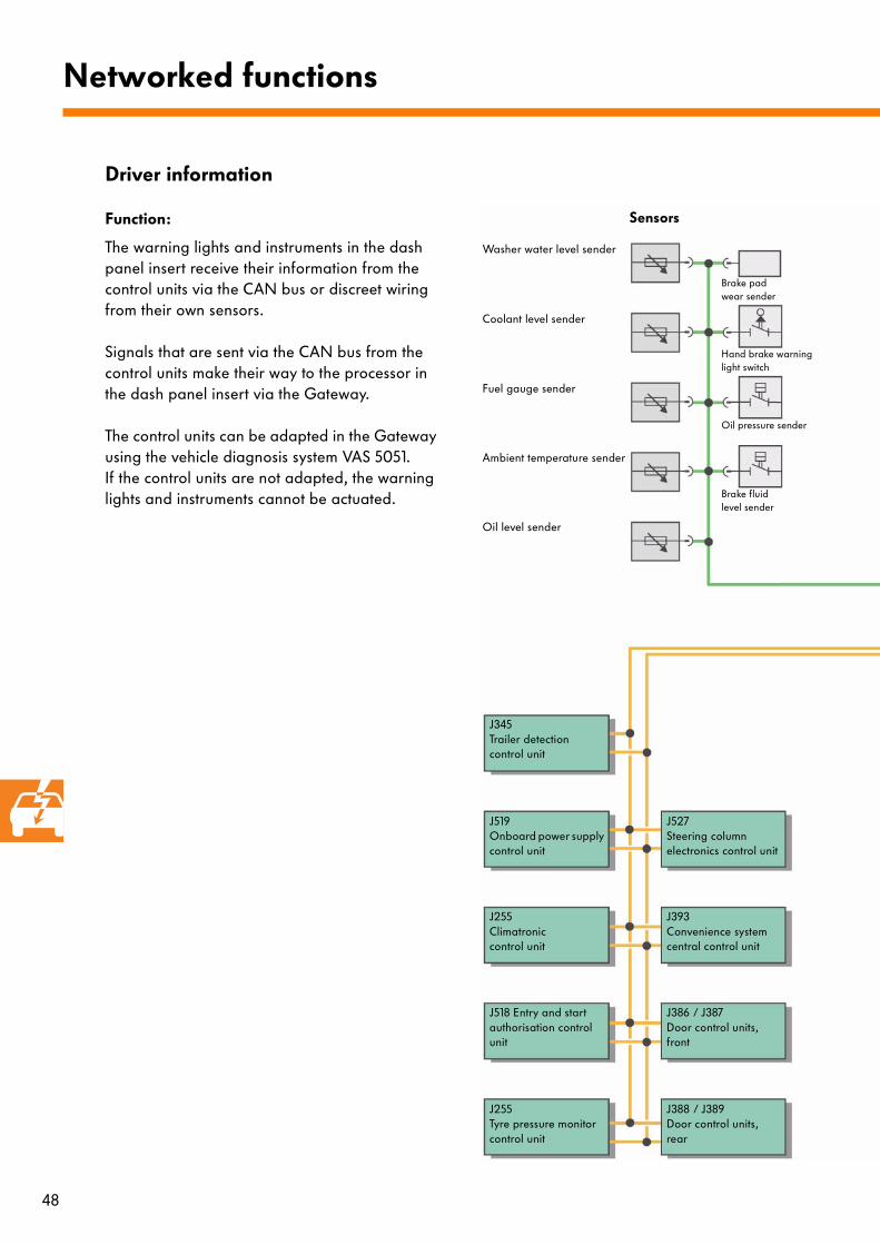
Function:
The warning lights and instruments in the dash panel insert receive their information from the control units via the CAN bus or discreet wiring from their own sensors.
Signals that are sent via the CAN bus from the control units make their way to the processor in the dash panel insert via the Gateway.
The control units can be adapted in the Gateway using the vehicle diagnosis system VAS 5051. If the control units are not adapted, the warning lights and instruments cannot be actuated.
Driver information
Networked functions
Brake pad wear sender
Hand brake warning light switch
Oil pressure sender
Brake fluid level sender
Oil level sender
Ambient temperature sender
Fuel gauge sender
Coolant level sender
Washer water level sender
Sensors
J345 Trailer detection control unit
J519Onboard power supply control unit
J255Climatronic control unit
J518 Entry and start authorisation control unit
J255 Tyre pressure monitor control unit
J388 / J389Door control units, rear
J386 / J387Door control units, front
J393 Convenience system central control unit
J527Steering column electronics control unit
49
S298_036
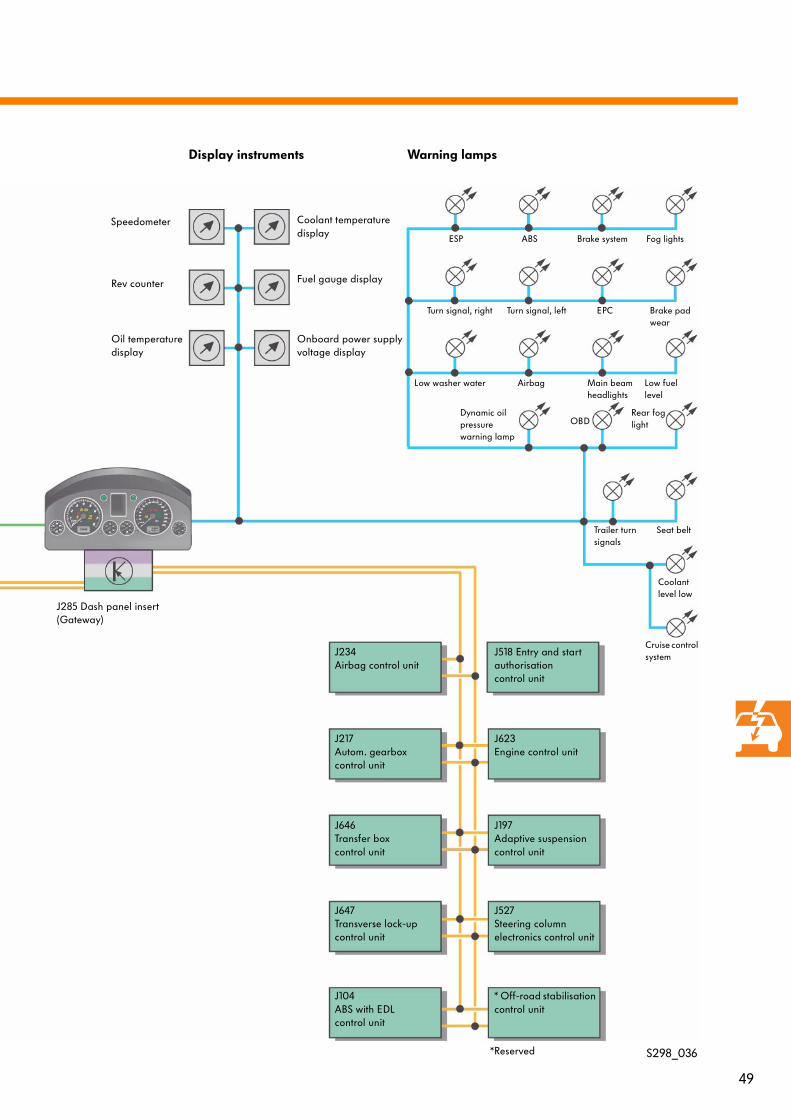
Coolant temperature display
Warning lamps
ESP
Low washer water
ABS Fog lights
Turn signal, right Turn signal, left Brake pad wear
Airbag Main beam headlights
Low fuel level
Dynamic oil pressure warning lamp
Coolant level low
Rear fog light
Brake system
EPC
Seat belt
Cruise control system
Trailer turn signals
OBD
J234Airbag control unit
J217 Autom. gearbox control unit
J647Transverse lock-up control unit
J104 ABS with EDL control unit
* Off-road stabilisation control unit
J527 Steering column electronics control unit
J197Adaptive suspension control unit
J623 Engine control unit
J518 Entry and start authorisation control unit
Fuel gauge display
Onboard power supply voltage display
Speedometer
Rev counter
Oil temperature display
Display instruments
J285 Dash panel insert (Gateway)
J646 Transfer box control unit
*Reserved
50
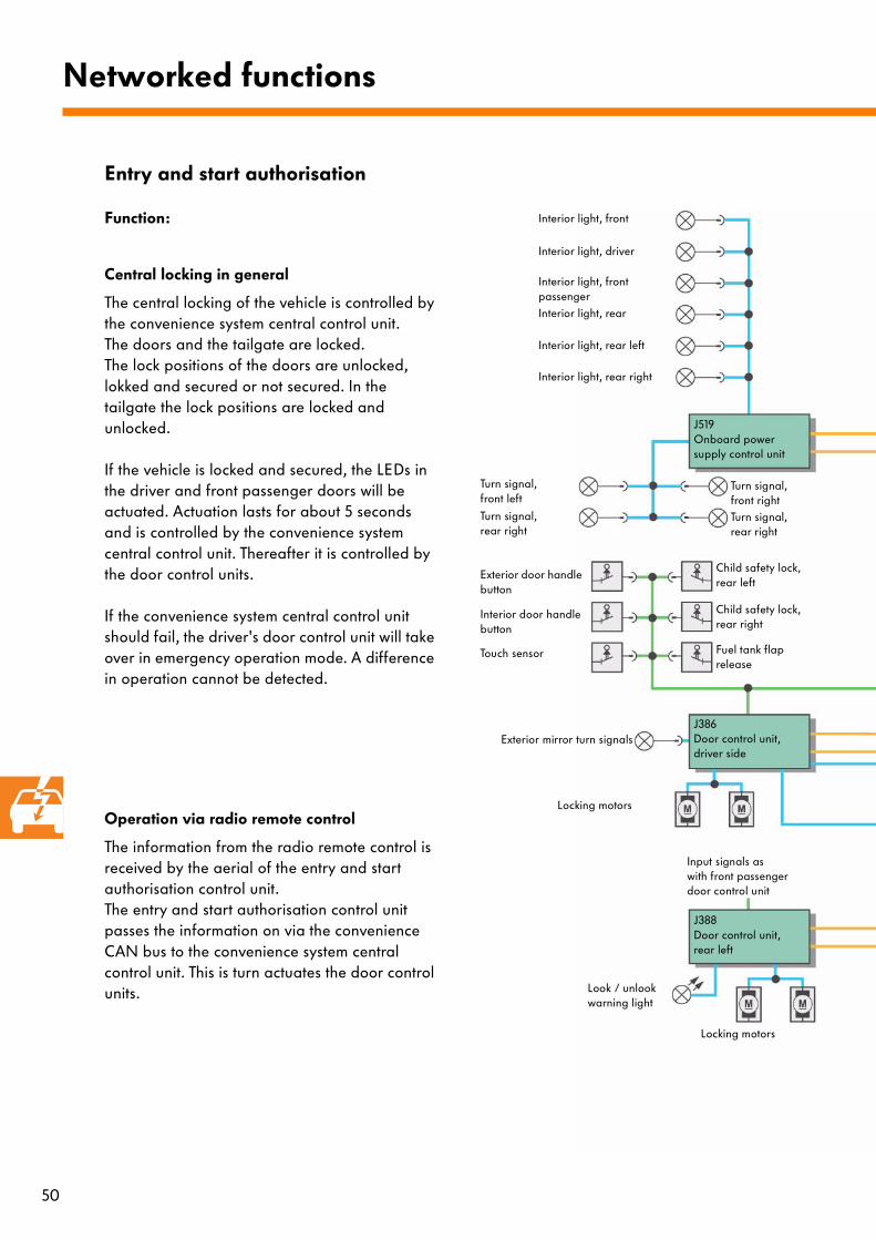
Function:
Central locking in general
The central locking of the vehicle is controlled by the convenience system central control unit. The doors and the tailgate are locked. The lock positions of the doors are unlocked, lokked and secured or not secured. In the tailgate the lock positions are locked and unlocked.
If the vehicle is locked and secured, the LEDs in the driver and front passenger doors will be actuated. Actuation lasts for about 5 seconds and is controlled by the convenience system central control unit. Thereafter it is controlled by the door control units.
If the convenience system central control unit should fail, the driver's door control unit will take over in emergency operation mode. A difference in operation cannot be detected.
Operation via radio remote control
The information from the radio remote control is received by the aerial of the entry and start authorisation control unit. The entry and start authorisation control unit passes the information on via the convenience CAN bus to the convenience system central control unit. This is turn actuates the door control units.
Networked functions
Entry and start authorisation
J388 Door control unit, rear left
J386 Door control unit, driver side
J519Onboard power supply control unit
Turn signal, front left
Locking motors
Turn signal, front rightTurn signal, rear right
Exterior door handle button
Interior door handle button
Touch sensor
Input signals as with front passenger door control unit
Locking motors
Look / unlook warning light
Turn signal, rear right
Exterior mirror turn signals
Child safety lock,rear left
Child safety lock,rear right
Fuel tank flap release
Interior light, front
Interior light, driver
Interior light, front passengerInterior light, rear
Interior light, rear left
Interior light, rear right

51
J518 Entry and start authorisation control unit
J387 Front passenger door control unit
J389 Door control unit, rear right
J383Convenience system central control unit
J234Airbag control unit
J285 Dash panel insert (Gateway)
Fuel tank flap release
Warning lamps
Locking motors
Input signals as with front passenger door control unit
Look / unlook warning light
Look / unlook warning light
Locking motors
Tailgate switch
Motors for fuel tank flap releasetailgate releasetailgate window releasepower latch
Anti-theft alarm system horn
Keyless entry aerials
S298_037
Unlook button
Locked message
Lock switch open
Rotary door latch
Look button
Secured message
Lock switch closed
Look / unlook
Central locking
Child safety lock,rear left
Child safety lock,rear right
Interior monitoring sensor
Rotary door latch
Touch sensor
Secured message
Lock switch closed
Interior door handle button
Exterior door handle button
Locked message
Lock switch open
Exterior mirror turn signals
Central locking

52
Operation via proximity sensors
Apart from opening the door, no other action is necessary. The entry and start authorisation control unit detects the transponder in the ignition key. When the door handle is actuated, the action is detected by the entry and start authorisation control unit by means of a signal. A signal is then also sent via the convenience CAN bus to the convenience system central control unit. This actuates the relevant door control unit.
Activating and deactivating the anti-theft alarm system
The anti-theft alarm system is activated in positions locked or secured. If the ignition is switched on, the anti-theft alarm system cannot be activated. An active anti-theft alarm system is displayed by the central locking warning lights in the front doors for a maximum of 28 days.
Networked functions
J388 Door control unit, rear left
J386 Door control unit, driver side
J519Onboard power supply control unit
Turn signal, front left
Locking motors
Turn signal, front rightTurn signal, rear right
Exterior door handle button
Interior door handle button
Touch sensor
Input signals as with front passenger door control unit
Locking motors
Look / unlook warning light
Turn signal, rear right
Exterior mirror turn signals
Child safety lock,rear left
Child safety lock,rear right
Fuel tank flap release
Interior light, front
Interior light, driver
Interior light, front passengerInterior light, rear
Interior light, rear left
Interior light, rear right

53
J518 Entry and start authorisation control unit
J387 Door control unit,front passenger side
J389 Door control unit, rear right
J383Convenience system central control unit
J234Airbag control unit
J285 Dash panel insert (Gateway)
Fuel tank flap release
Warning lamps
Locking motors
Input signals as with front passenger door control unit
Look / unlook warning light
Look / unlook warning light
Locking motors
Tailgate switch
Motors for fuel tank flap releasetailgate releasetailgate window releasepower latch
Anti-theft alarm system horn
Keyless entry aerials
S298_037
Unlook button
Locked message
Lock switch open
Rotary door latch
Look button
Secured message
Lock switch closed
Look / unlook
Central locking
Child safety lock,rear left
Child safety lock,rear right
Interior monitoring sensor
Rotary door latch
Touch sensor
Secured message
Lock switch closed
Interior door handle button
Exterior door handle button
Locked message
Lock switch open
Exterior mirror turn signals
Central locking

54
Headlights with safety locksRemoving headlights
The headlights are designed based on the principle of sliding drawers. They can be pulled out. To do this, a socket must be used on a hexagon drive to unscrew the headlights. This releases the lock and the headlight can be removed.
The direction of rotation differs on the left and right.
Rear lights
On the fixed part of the rear light cluster, the lamp must be removed to replace the bulb.
The bulbs of the rear light in the tailgate can be replaced by changing the lamp holder.
Service
S298_030
Lock
Direction of rotation for right headlight
Hexagon drive
Rear lights
Fixed part Lamp holder in tailgate
S298_046
The lighting

55
Guided fault finding
The data from the guided fault finding function is interrogated by the vehicle diagnosis, testing and information system VAS 5051.
To do this, the guided fault finding function must be selected. All the necessary information can be found there.
The data is interrogated via a diagnosis interface for the data bus in the dash panel insert.
A wired communication connection is only necessary to some control units in the drive train CAN bus, to control units for gas discharge lamps and to the convenience system central control unit.
VAS 5051
Drive Train CAN bus
Convenience CAN bus
Infotainment CAN bus
J285Dash panel insert (Gateway)
Diagnosis lead
CAN bus wiring
S298_047
Signal sequence
Simplified view: The data bus systems have different data wires to the Gateway.
Diagnosis

56
CAN bus
Bi-directional data wire between control units. The data can be sent in both directions (bi-directional). Data buses work at different rates of data transfer. 500 kBit/s means that 500 000 binary figures, that is 0 or 1, can be sent per second.
Discreet signal
This is a voltage signal which is sent via a normal cable.
Gateway
This is a data interface (connection), which allows different data signals to be sent from one CAN bus to another.
Glossary

57

58
Test yourself
1. Which control units belong to the Drive Train CAN bus?
a) The airbag control unit, the convenience system central control unit, the tyre pressure monitor control unit.
b) The steering column electronics control unit, the entry and start authorisation control unit, the engine control unit, the airbag control unit.
c) The wiper motor control unit, the door control units, the rear blind control unit, the airbag control unit.
2. Where can the battery main / isolation switch E 74 be found?
a) In the luggage compartment, next to the starter battery.
b) In the engine compartment, near the alternator.
c) In the back-up fuse box, under the driver's seat.
3. If the voltage of the onboard power supply battery is below 11.2 Volt,
a) it is discharged.
b) it is weak, but not discharged.
c) the alternator is defective and must be replaced.

59
4. Which functions are controlled by the onboard power supply?
a) The parking light, fog lamps, twin washer pump.
b) The brake lights, the rear turn signals, the power latch function in the tailgate.
c) The wiper motor, the central locking, the sliding/tilting sunroof.
5. Which lighting settings can be carried out in the set-up menu of the dash panel insert?
a) Change in the flash frequency of the turn signals.
b) Day driving light in countries where there is no legal requirement for them to be on permanently.
c) The brightness of the footwell lighting.
6. Which control units play a role in the "Automatic driving light" function?
a) The onboard power supply control unit, the wiper motor control unit, the convenience system central control unit.
b) The steering column electronics control unit, the onboard power supply control unit, the trailer detection control unit.
c) The entry and start authorisation control unit, the onboard power supply control unit, the convenience lighting control unit.
Answers:1. b2. c3. b4. a5. b, c6.a
For internal use only © VOLKSWAGEN AG, Wolfsburg
All rights and technical alterations reserved
000.2811.18.20 Technical status 09/02
❀ This paper was made from pulp which was bleached
without the use of chlorine
298