the 2015 audi a3 onboard power supply and networking …
TRANSCRIPT

2
• The Self Study Programme teaches a basic knowledge of the design and functions of new models, new automotive components or new technologies. It is not a Repair Manual! Figures are given for explanatory purposes only and refer to the data valid at the time of preparation of the SSP. For further information about maintenance and repair work, always refer to the current technical literature.
Note
Reference
The 2015 Audi A3 Onboard Power Supply and Networking Systems
eSelf Study Program 970243

3
Audi of America, LLC Service Training Created in the U.S.A. Created 11/2013 Course Number 970243
©2013 Audi of America, LLC
All rights reserved. Information contained in this manual is based on the latest information available at the time of printing and is subject to the copyright and other intellectual property rights of Audi of America, LLC., its affiliated companies and its licensors. All rights are reserved to make changes at any time without notice. No part of this document may be reproduced, stored in a retrieval system, or transmitted in any form or by any means, electronic, mechanical, photocopying, recording or otherwise, nor may these materials be modified or reposted to other sites without the prior expressed written permission of the publisher.
All requests for permission to copy and redistribute information should be referred to Audi of America, LLC.
Always check Technical Bulletins and the latest electronic service repair literature for information that may supersede any information included in this booklet.
Revision 1: 11/2013

4
ContentsPower supply ......................................................................................6Battery ...................................................................................................................................................6Battery housing ....................................................................................................................................6Fuses, relays and jump start terminal ................................................................................................7
Networking .........................................................................................9Installation locations of control modules ..........................................................................................9Topology ..............................................................................................................................................11Overview of bus systems ....................................................................................................................13New features of the bus system .......................................................................................................13Optical data bus system MOST150 ...................................................................................................14Special tool VAS 6778 ........................................................................................................................14
Control modules ...............................................................................15Brief descriptions ................................................................................................................................15
Exterior lighting ...............................................................................29Light switch .........................................................................................................................................29Headlights ...........................................................................................................................................30Headlight range control .....................................................................................................................32Tail lights .............................................................................................................................................34High-mounted brake light ..................................................................................................................35License lights ......................................................................................................................................35
eSelf Study Programs .......................................................................36
Knowledge Assessment ...................................................................38

This eSelf Study Program teaches a basic knowledge of the design and functions of new models, new automotive components or technologies. It is not a Repair Manual! All values given are intended as a guideline only. For maintenance and repair work, always refer to the current technical literature.
Note
Reference
6
Battery
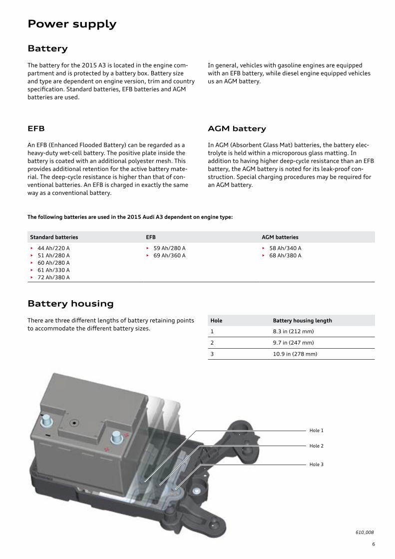
The battery for the 2015 A3 is located in the engine com-partment and is protected by a battery box. Battery size and type are dependent on engine version, trim and country specification. Standard batteries, EFB batteries and AGM batteries are used.
In general, vehicles with gasoline engines are equipped with an EFB battery, while diesel engine equipped vehicles us an AGM battery.
The following batteries are used in the 2015 Audi A3 dependent on engine type:
Standard batteries EFB AGM batteries
• 44 Ah/220 A• 51 Ah/280 A• 60 Ah/280 A• 61 Ah/330 A• 72 Ah/380 A
• 59 Ah/280 A• 69 Ah/360 A
• 58 Ah/340 A• 68 Ah/380 A
EFB
An EFB (Enhanced Flooded Battery) can be regarded as a heavy-duty wet-cell battery. The positive plate inside the battery is coated with an additional polyester mesh. This provides additional retention for the active battery mate-rial. The deep-cycle resistance is higher than that of con-ventional batteries. An EFB is charged in exactly the same way as a conventional battery.
AGM battery
In AGM (Absorbent Glass Mat) batteries, the battery elec-trolyte is held within a microporous glass matting. In addition to having higher deep-cycle resistance than an EFB battery, the AGM battery is noted for its leak-proof con-struction. Special charging procedures may be required for an AGM battery.
There are three different lengths of battery retaining points to accommodate the different battery sizes.
Battery housing
Hole Battery housing length
1 8.3 in (212 mm)
2 9.7 in (247 mm)
3 10.9 in (278 mm)
610_008
Hole 1
Hole 3
Hole 2
Power supply

7
Fuses, relays and jump start terminal
The positive terminal on the battery and the jump start terminal on the engine compartment bulkhead are used for charging the battery and jump starting.
In addition to standard fuses, the space-saving mini-fuses and circuit breakers (thermal fuses), a new J-Case fuse is being used. As with other fuses, they are identifiable by their color.
Fuse rating Color
20 A blue
25 A white
30 A pink
40 A green
50 A red
60 A yellow
A new gripping tool is used to remove and install the J-Case fuse. It is stored in the cover of the E-box in the engine compartment.
610_073
610_071
610_072
Gripping tool for J-Case fuses
J-Case fuses
Battery ground terminal and Battery Monitoring Control Module J367
Battery A
Jump start terminal on the engine bulkhead
Fuse rail in the E-box with fuses identified by “SA” in the Wiring Diagrams.
E-box with fuses and relays identi-fied by “SB” in the Wiring Dia-grams.
Fuse holder and relay carrier under the instrument panel with the designation “SC” in the Wiring Diagrams
Battery positive

8
Notes

9
J623
J668
J667
J104
J743
J500
J745
J518
J685
R242
J533
J764
J519
J794
J255
J285J527
J587J234
J386
J387
J428
J525
J250
E380
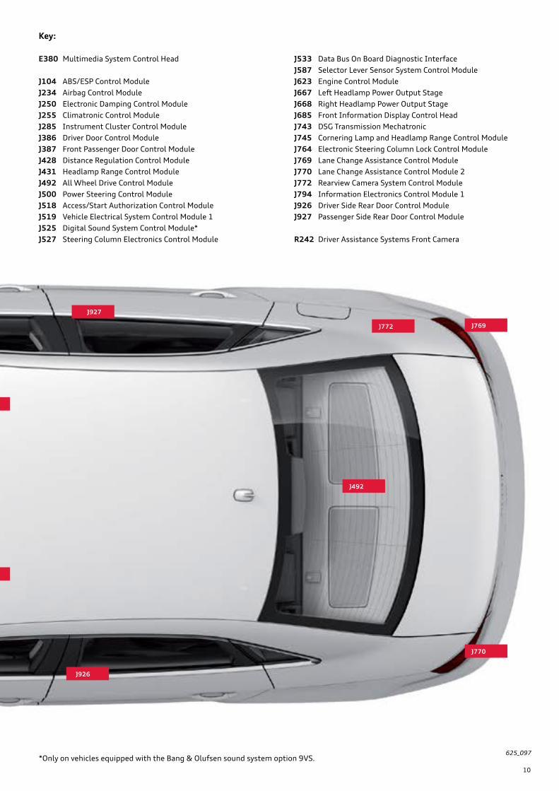
Some of the control modules shown in the overview may be optional and/or country specific equipment.
Installation locations of control modules
Always refer to the current service literature for complete details about control module locations as well as instruc-tions for their removal and installation.
Networking
J431
10
J926
J927
J525
J250
J772
J492
J769
J770
625_097*Only on vehicles equipped with the Bang & Olufsen sound system option 9VS.
Key:
E380 Multimedia System Control Head
J104 ABS/ESP Control ModuleJ234 Airbag Control ModuleJ250 Electronic Damping Control ModuleJ255 Climatronic Control ModuleJ285 Instrument Cluster Control ModuleJ386 Driver Door Control ModuleJ387 Front Passenger Door Control ModuleJ428 Distance Regulation Control ModuleJ431 Headlamp Range Control ModuleJ492 All Wheel Drive Control ModuleJ500 Power Steering Control ModuleJ518 Access/Start Authorization Control Module J519 Vehicle Electrical System Control Module 1J525 Digital Sound System Control Module*J527 Steering Column Electronics Control Module
J533 Data Bus On Board Diagnostic InterfaceJ587 Selector Lever Sensor System Control ModuleJ623 Engine Control ModuleJ667 Left Headlamp Power Output StageJ668 Right Headlamp Power Output StageJ685 Front Information Display Control HeadJ743 DSG Transmission MechatronicJ745 Cornering Lamp and Headlamp Range Control ModuleJ764 Electronic Steering Column Lock Control ModuleJ769 Lane Change Assistance Control ModuleJ770 Lane Change Assistance Control Module 2J772 Rearview Camera System Control ModuleJ794 Information Electronics Control Module 1J926 Driver Side Rear Door Control ModuleJ927 Passenger Side Rear Door Control Module
R242 Driver Assistance Systems Front Camera

11
Topology
Passenger Side Rear Door Control Module J927
Steering Column Electronics Control ModuleJ527
Driver Door Control Module J386
Electrical Steering Column Lock Control Module J764
Anti-theft Alarm System SensorG578
Driver Side Rear Door ControlModule J926
Front Passenger Door Control Module J387
Vehicle Electrical System Control Module J519
Access/Start Authorization Control Module J518
Rain/Light Recognition Sensor G397
Humidity sensorG355
Alarm hornH12
Light switch E1
Wiper motor control unitJ400
Power Sunroof Control Module J245
Instrument Cluster Control Module J285
Climatronic Control Module J255
Fresh Air Blower Control ModuleJ126
Refrigerant Circuit Pressure SensorG805
Air quality sensorG238
Humidity Sensor in Fresh Air Intake DuctG657
Data Link Connector
Engine Control Module J623
Airbag Control ModuleJ234
Nox Sensor Control Module J583*
Nox Sensor Control Module 2 J881*
Left Front Seat Belt Tensioner Control Module J854
Right Front Seat Belt Tensioner Control Module J855 DSG Transmission
Mechatronic J743
Selector Lever Sensor System Control Module J587
Data Bus Onboard Diagnostic Interface J533
Passenger Occupant Detection System Control Module J706
Lane Change Assistance Control Module 2 J770
Power output module for left LED headlight
Power output module for right LED headlight
Multifunction steering wheel control unitJ453
Headlight power module, leftJ667
Headlight power module, rightJ668
*2.0L TDI engine only
The topology shows all control modules with connectivity to the data bus system. Some of the control modules shown here are optional, country-specific equipment, or will be introduced at a later date. Be aware that all the modules shown will not be installed on every vehicle.

12
Headlamp Range Control Module J431
AlternatorC
Battery Monitoring Control Module J367
Lane Change Assistance Control Module J769
Digital Sound System Control Module J525
Information Electronics Control Module 1 J794
Rearview Camera System Control Module J772
Front Information Display Control Head J685
Multimedia System Control Head E380
Distance Regulation Control Module J428
Driver Assistance Systems Front Camera J842
Cornering Lamp and Headlight Range Control Module J745
Electronic Damping Control Module J250
All Wheel Drive Control Module J492
Power Steering Control Module J500
ABS/ESP Control Module J104
Convenience CAN bus
Powertrain CAN bus Infotainment CAN bus
Diagnostics CAN bus
Extended CAN bus Suspension CAN bus
LIN bus
Sub-bus systems
Key:
MOST bus
610_001_pkd
For example, Cornering Lamp and Headlight Range Control Module J745 would never be installed on the same vehicle as Headlamp Range Control Module J431.

13
Bus system Cable color Configuration Max. data transfer rate Characteristic
Powertrain CAN bus Electrical two-wire bus system
500 kbit/s Not single-wire capable
Convenience CAN bus Electrical two-wire bus system
500 kbit/s Not single-wire capable
Extended CAN bus Electrical two-wire bus system
500 kbit/s Not single-wire capable
Infotainment CAN bus Electrical two-wire bus system
500 kbit/s Not single-wire capable
Suspension CAN bus Electrical two-wire bus system
500 kbit/s Not single-wire capable
Diagnostics CAN bus Electrical two-wire bus system
500 kbit/s Not single-wire capable
MOST bus Optical bus system 150 Mbit/s Ring structure: an open circuit leads to total system failure
LIN bus Electrical single-wire bus system
20 kbit/s Single-wire capable
Sub-bus system(private bus)
Electrical two-wire bus system
500 kbit/s Not single-wire capable
• The Convenience CAN and Infotainment CAN are high-speed systems on the 2015 A3.
• New MOST bus – MOST150 (MOST150 has replaced MOST50).
• Instrument Cluster Control Module J285 is a Conveni-ence CAN participant.
• Data Bus On Board Diagnostic Interface J533 is the master of LIN slave Multifunction Steering Wheel Control Module J453.
• J533 is not a MOST bus participant.
• Information Electronics Control Module 1 J794 is the system and diagnostic manager for the MOST 150 bus.
• Information Electronics Control Module 1 J794 is con-nected to the MMI operating unit and display through a sub-bus system.
Overview of bus systems
New features of the bus system

14
History
This data bus system is named after the "Media Oriented Systems Transport (MOST) Cooperation". This group is made up of various automobile manufacturers, their com-ponents suppliers and software companies, who joined forces to create a standardized high-speed data transfer system. It was used for the first time in the 2004 Audi A8.
The term “Media Oriented Systems Transport” denotes a network that unlike the CAN data bus, sends address ori-ented messages to specific users. This technology is used by Audi to transfer data within the Infotainment system.
MOST150
The MOST150 bus is used for the first time by Audi in the new 2015 A3. It is six times faster than MOST25 and necessitated some modifications to MOST components.
For instance, the transmitter and receiver units – Fiber Optical Transmitters (FOT) – had to be adapted. Other components, such as the optical connectors, the fiber optics and the electrical connections of the control units, are identical to those of the MOST25.
System manager
Two control modules participate on the MOST150 bus in the 2015 A3:
• Information Electronics Control Module 1 J794• Digital Sound System Control Module J525
In the 2015 A3, Information Electronics Control Module 1 J794 functions as the system manager and diagnostic manager for the MOST150 system. The was previously done by Data Bus On Board Diagnostic Interface J533.
Diagnostics
The ring break diagnosis procedure is identical to that of the previous MOST bus system. However, the Address Word for the 2015 A3 is 5F.
Even though the ring break diagnosis procedure remains unchanged, a new special tool - VAS 6778 - must be used if there is a DTC in the optical system. This is due to the increased data transmission speeds.
610_069
610_074
Digital Sound System Control Module J525
Information Electronics Control Module 1 J794
Optical data bus system MOST150
Special tool VAS 6778

15
ReferenceFor a detailed description of Vehicle Electrical System Control Module J519, please see eSelf-Study Program 970343, The 2015 Audi A3 Vehicle Electronics and Drivers Assistance Systems.
Brief descriptions
Designation Vehicle Electrical System Control Module J519
Equipment Always installed
Installation position Under the left side of the instrument panel
Tasks • Central locking master• Exterior light master• Interior light master• Antitheft alarm master• Activation of various relays• Activation of various convenience components:
• Seat heaters• Heated windshield washer nozzles• Windshield washer pump• Headlight washer system pump
• Reading various switch and button positions• Reading various sensor values
Address Word 09
Data bus communication • Convenience CAN bus participant• J519 is the LIN master for:
• LIN 1 – Light Switch 1, Wiper Motor Control Module J400, Rain/Light Recognition Sensor G397, Humidity Sensor G355
• LIN 2 – Alarm Horn H12• LIN 3 – Power Sunroof Control Module J245, Anti-theft Alarm System Sensor G578
Special feature LIN 1 is distributed to two pins on J519. J400 is connected to pin B30. E1, G397 and G355 – are connected to pin C28. This means that the control modules connected to pin C28 are also affected in the event of a short circuit to positive or negative at pin B30.
Vehicle electrics
610_009
J519
Control modules

16
Gateway
Designation Data Bus On Board Diagnostic Interface J533 (Gateway)
Equipment Always installed
Installation position Under the left side of the instrument panel
Tasks • Networking gateway• Diagnostic master (with the exception of MOST150)• Energy management system control• Master for multifunction steering wheel / optional equipment
Address Word 19
Data bus communication • All CAN bus system participant• LIN master of Battery Monitoring Control Module J367 and alternator• LIN master of multifunction Multifunction Steering Wheel Control Module J453
Special feature Not a MOST bus user
Instrument cluster / DIS
Designation Instrument Cluster Control Module J285
Equipment Always installedVersions:• Monochrome DIS with onboard computer, PR No.: 9S5• Color DIS with onboard computer, PR No.: 9S6
Installation position Instrument Panel
Tasks • Display of information relevant to the driver • Immobililzer master
Address Word 17
Data bus communication Convenience CAN bus participant
Special feature Convenience CAN participant for first time on an Audi model
610_010
610_011
J285 (European version shown)
J533

17
Steering column electronics
Designation Steering Column Electronics Control Module J527
Equipment Always installed
Installation position On the steering column
Tasks • Connects the steering column stock and the electrical components in the steering wheel to the vehicle electronics
• Terminal management master for vehicles without advanced key
Address Word 16
Data bus communication Convenience CAN bus participant
Special feature Transfers the LIN signals from J533 (Gateway) to Multifunction Steering Wheel Control Module J453 in models equipped with a multifunction steering wheel
610_012
J527
Heating / air conditioning
DesignationA/C Control Module J301Climatronic Control Module J255
Equipment • Air conditioning system, PR No.: KH6• Climatronic, PR No.: 9AK
Installation position In center of instrument panel
Tasks Controlling:• Temperature• Blower• Air distribution
Address Word 08
Data bus communication • Convenience CAN bus participant• J301 is also the LIN master of Refrigerant Circuit Pressure Sensor G805• J255 is also the LIN master of Air Quality Sensor G238 and Humidity Sensor in Fresh Air Intake Duct
G657
Special feature All LIN slaves are connected to a LIN output.
610_015 610_016
J255J301

18
Designation Front Passenger Door Control Module J387
Equipment Always installed
Installation position In the front passenger's door
Task Controlling the electrical and electronic components in and on the front passenger's door
Address Word 52
Data bus communication • Convenience CAN bus participant• In 5-door models it is connected to Passenger Side Rear Door Control Module J927 via a LIN line
Special feature Activates the side marker lights in the front passenger door mirror
Front passenger side door electronics
610_018
Designation Driver Door Control Module J386
Equipment Always installed
Installation position In the driver's door
Task Controlling the electrical and electronic components in and on the driver's door
Address Word 42
Data bus communication • Convenience CAN bus participant• In 5-door models it is connected to Driver Side Rear Door Control Module J926
Special features • J386 acts as the substitute master for the central locking system in the event of failure of Vehicle Electri-cal System Control Module J519
• Activates the side marker lights in the driver's door mirror
Door electronics, driver side
610_017
J386
J387

19
Designation Access/Start Authorization Control Module J518
Equipment Optional equipment, PR No.: 4F2
Installation position Under the instrument panel
Tasks • Reads signals from both capacitive sensors• Activation of the entry and start authorization antennas
Address Word B7
Data bus communication Convenience CAN bus participant
Special feature External antennas connected to J518 are not installed in the doors but rather on the vehicle underbody near the ‘B’ pillars.
Advanced key / keyless entry and start authorization
610_019
J518
610_020
Designation Electronic Steering Column Lock Control Module J764
Equipment Optional advanced key, PR No.: 4I3
Installation position On the steering column
Tasks • Locking and unlocking the steering column• Terminal management master
Address Word 2B
Data bus communication Convenience CAN bus participant
Special features • Can be replaced separately from the steering column• Immobilizer participant• Reads signals from the entry and start authorization button
Electrical steering column lock
J764

20
Designation Rearview Camera System Control Module J772
Equipment Optional equipmentVersion:• Parking aid (front/rear) with back-up camera, PR No.: 7X2+KA2
Installation position Behind the side trim on the right-hand side of the luggage compartment
Tasks • Converting and processing the raw images captured by the rearview camera• Transferring the processed images to Information Electronics Control Module J794
Address Word 6C
Data bus communication Convenience CAN bus participant
Special features • Video connections are mechanically encoded• Only two of the three connections are used
Back-up camera
610_025Electrical connection
Video output
Back-up camera connection
Unused
Designation Distance Regulation Control Module J428
Equipment Optional equipment for vehicles with:• Stronic, PR No.: 8T3• pre sense front, PR No.: 7W2
Installation position Behind center of front grille below license plate mount
Tasks • Radar scanning of traffic• Controlling speed and distance
Address Word 13
Data bus communication CAN-Extended bus participant
Special feature Independent braking to a standstill behind a vehicle driving ahead and independent restarting (ACC Stop & Go)
Audi adaptive cruise control
Audi pre sense front
610_043
J428
J772

21
Designation Digital sound package control unit J525
Equipment Installed on all vehicles Bang & Olufsen sound system
Installation position Under the driver’s seat
Task Activation of the speakers
Address Word 47
Data bus communication MOST bus participant
Sound amplifier*
610_027
J525
Designation Information Electronics Control Module 1 J794
Equipment Versions:• MMI Radio, PR No.: I8B• MMI Navigation plus, PR No.: I8F, 7UG
Installation position In the glove compartment
Task Controlling the infotainment systems
Address Word 5F
Data bus communication Infotainment CAN bus participant
Special features J794 is the system manager as well as the ring break diagnostics master for the MOST bus
Infotainment
610_026
J794 (MMI navigation plus with Audi connect module shown)
*The sound amplifier for vehicles equipped with the Audi sound system is integrated with Information Electronics Control Module 1 J794.

22
Designation ABS/ESP Control Module J104
Equipment Always installed
Installation position • On the right side of the engine compartment near the bulkhead
Tasks • Anti lock braking system ABS• Electronic Stabilization Program ESP• Traction Control System TCS• Electronic Differential Lock EDL • Electronic transverse lock• Post collision brake assist• Electro-mechanical parking brake EPB
Address Word 03
Data bus communication Suspension CAN bus participant
Special features • The control module can be replaced separately from the valve block using ESD protective mat VAS 6613• The electro-mechanical parking brake is integrated in the ABS control module. Address Word 53 for
electro-mechanical parking brake has been deleted.
Electronic Stabilization Program ESP
610_029
ReferenceFor detailed descriptions of the suspension components refer to eSelf-Study Program 960143, The 2015 Audi A3 Running Gear and Suspension.
Designation Power Steering Control Module J500
Equipment Always installed
Installation position Connected to the steering gear
Tasks • Power steering• Servotronic – speed-dependent power steering• Corrective steering intervention in combination with Audi active lane assist• Corrective steering intervention in combination with ESP
Address Word 44
Data bus communication Suspension CAN bus participant
Special features • Control module with power steering motor and Steering Angle Sensor G85 can only be replaced together with the steering gear
• G85 has no separate data bus connections; data is transferred via Power Steering Control Module J500
Power steering
610_030
J500
J104
Hydraulic unit

23
Designation All Wheel Drive Control Module J492
Equipment Standard equipment with quattro drive train
Installation position Connected externally to the rear axle gear
Task Control of the Haldex coupling according to the driving situation
Address Word 22
Data bus communication Suspension CAN bus participant
Special feature The control can be replaced separately without removing the rear axle gear
All-wheel drive
610_031
Designation Parallel Parking Assistance Control Module J791
Equipment Optional equipmentVersion:• Parking aid plus, PR No.: 7X2
Installation position Behind instrument panel on left side
Tasks Reads signal from ultrasound sensors and issues audible or visual warnings
Address Word 76
Data bus communication Suspension CAN bus participant
Special feature Address Word changed from 10 to 76 . Will only control front and rear acoustic sensors on vehicles for the North American region.
Parking aid
610_032
J492
J791

24
Designation Electronic Damping Control Module J250
Equipment Optional equipment, PR No.: 2H7
Installation position Under the right-hand front seat
Task Adaptation of the damping characteristic
Address Word 14
Data bus communication Suspension CAN bus participant
Audi magnetic ride
610_033
Designation Engine Control Module J623
Equipment Always installed
Installation position In the engine compartment between battery and E-box
Task Controlling the engine operating characteristics
Address Word 01
Data bus communication Powertrain CAN bus participant
Special features • Engine Control Modules have differing terminating connectors depending on engine version installed• Immobilizer participant• Vehicles with an anti-theft alarm have an anti-theft device (sheet metal cover with shear bolts) over the
ECM
Engine control
610_034
J623
Antitheft protection
Shear bolt 1
J250
Shear bolt 2

25
Airbag / Audi pre sense basic
610_035
Designation DSG Transmission Mechatronic J743
Equipment Always installed on vehicles with S tronic
Installation position On the transmission
Task Controling the dual clutch transmission
Address Word 02
Data bus communication Powertrain CAN bus participant
Special feature Dual clutch transmission 09D (6-speed) is used.
S tronic
610_036
J234
J743
Designation Airbag Control Module J234
Equipment • Always installed• Audi pre sense basic, PR No.: 7W1. Optional Audi pre sense front, PR No.: 6K3
Installation position On the center tunnel in front of the center console
Tasks • Deployment of the airbags• Audi pre sense
Address Word 15
Data bus communication • Powertrain CAN bus participant• J234 is the LIN master for front left and right Seat Belt Tensioner Control Modules J854 and J855. • In vehicles specified for the North American market, J234 is the LIN master for Passenger Occupant
Detection System Control Module J706
26
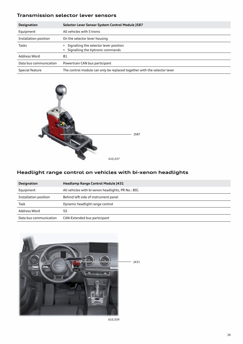
Designation Selector Lever Sensor System Control Module J587
Equipment All vehicles with S tronic
Installation position On the selector lever housing
Tasks • Signalling the selector lever position• Signalling the tiptronic commands
Address Word 81
Data bus communication Powertrain CAN bus participant
Special feature The control module can only be replaced together with the selector lever
Transmission selector lever sensors
610_037
Designation Headlamp Range Control Module J431
Equipment All vehicles with bi-xenon headlights, PR No.: 8IG
Installation position Behind left side of instrument panel
Task Dynamic headlight range control
Address Word 55
Data bus communication CAN-Extended bus participant
Headlight range control on vehicles with bi-xenon headlights
610_039
J431
J587

27
Headlight range control on vehicles with LED headlights
610_038
DesignationLane Change Assistance Control Module J769Lane Change Assistance Control Module 2 J770
Equipment Optional equipment, PR No.: 7Y1
Installation position • In the rear right bumper J769• In the rear left bumper J770
Task • To scan the peripheral area behind and to the side of the vehicle• To activate the warning lights in the door mirrors
Address Word 3C
Data bus communication • J769 (master) CAN-Extended bus participant• J770 (slave) connected to J769 via private CAN participant
Special feature The control modules are mounted in the bumper cover. The system must be calibrated after removal and installation.
Audi side assist
610_040
J769
J770
J745
Designation Cornering Lamp and Headlamp Range Control Module J745
Equipment On all vehicles with:• LED headlinghts, PR No.: 8IT
Installation position Behind the instrument panel on the left side
Task • Dynamic headlight range control• Controlling the light profiles• Controlling the adaptive light
Address Word 55
Data bus communication CAN-Extended bus participant
Special feature It is connected to the power modules for the left and right headlights via a private CAN bus

28
Designation Driver Assistance Systems Front Camera R242
Equipment Optional equipment• Audi active lane assist, PR No.: 7Y5
Installation position On the windshield, above the base of the interior rear-view mirror
Task Scanning and imaging of traffic, traffic signs and lane markers
Address Word A5
Data bus communication CAN-Extended bus participant
Special feature R242 now has all software needed for active lane assist operation
Audi active lane assist (lane departure warning system)
610_042
R242

29
For the 2015 A3, Light Switch E1 is a LIN slave of Vehicle Electrical System Control Module J519. The operating concept has been adopted from other Audi models.
Light switch
Designation Light Switch E1
Equipment Always installed
Installation position Left side of instrument panel
Task To indicate the driver's preferred light setting to Vehicle Electrical System Control Module J519
Address Word None, LIN slave, measurement values and diagnostics J519
Lights off (in some countries the daytime running light is switched on automatically when ignition is switched on).
The automatic daytime running light is switched on and off depending on the light sensor
Parking light
Low beam
0
AUTO
Function
Rotary switch:Upper control panel*
Lower control panel**
Rear fog light
Fog light
All-weather light in vehicles with LED headlights
Vehicle Electrical System Control Module J519 reads the four positions of the rotary switch, button operations and the position of the instrument lighting controller (where applicable) via the LIN circuit. All commands for the switch lighting and the warning lamps of the individual functions are sent to the light switch by J519.
A redundancy wire is used to determine the plausibility of the switch positions. In the event of a short circuit or open circuit in the LIN or redundancy lines, the emergency light function is activated by J519 (low beams are switched on) and a DTC is entered in J519.
Headlamp Range Control Adjuster E102* is integrated in the light switch housing but is a separate component. Its information is transmitted to the headlight range control servomotors via a discrete line.
Electrical connections and circuit
610_045
610_046
Control panel* Display and instrument lighting controller
Headlamp Range Control Adjuster E102*
Rotary switch
Connections of E102:
Pin 1 Terminal 30
Pin 2 Terminal 31
Pin 4 Activation of the headlight range control servomotors
Connections of E1:
Pin 1 LIN
Pin 2 Terminal 30
Pin 3 Terminal 31
Pin 4 Redundancy line
Light switch E1
Low beam
*These components are not installed on the 2015 Audi A3 at this time.** Available on S3 models only
Exterior lighting
30
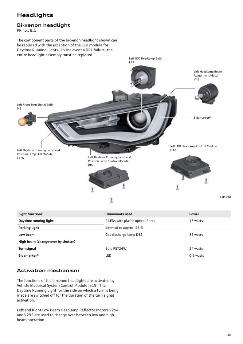
Bi-xenon headlightPR no.: 8IG
The component parts of the bi-xenon headlight shown can be replaced with the exception of the LED module for Daytime Running Lights. In the event a DRL failure, the entire headlight assembly must be replaced.
Light functions Illuminants used Power
Daytime running light 2 LEDs with plastic optical fibres
dimmed to approx. 25 %
18 watts
Parking light
Low beam Gas discharge lamp D3S 35 watts
High beam (change-over by shutter)
Turn signal Bulb PSY24W 24 watts
Sidemarker2) LED 0.6 watts
Activation mechanism
The functions of the bi-xenon headlights are activated by Vehicle Electrical System Control Module J519. The Daytime Running Light for the side on which a turn is being made are switched off for the duration of the turn signal activation.
Left and Right Low Beam Headlamp Reflector Motors V294 and V295 are used to change over between low and high beam operation.
610_048
Left Daytime Running Lamp and Position Lamp LED Module L176
Left HID Headlamp Bulb L13
Left Headlamp Beam Adjustment Motor V48
Sidemarker2)
Left HID Headlamp Control Module J343
Left Daytime Running Lamp and Position Lamp Control Module J860
Left Front Turn Signal Bulb M5
Headlights
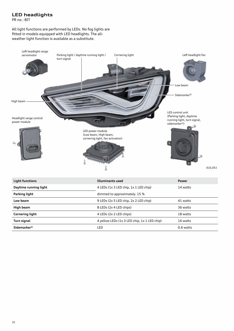
31
Light functions Illuminants used Power
Daytime running light 4 LEDs (1x 3 LED chip, 1x 1 LED chip)
dimmed to approximately. 15 %
14 watts
Parking light
Low beam 9 LEDs (2x 5 LED chip, 2x 2 LED chip) 41 watts
High beam 8 LEDs (2x 4 LED chips) 36 watts
Cornering light 4 LEDs (2x 2 LED chips) 18 watts
Turn signal 4 yellow LEDs (1x 3 LED chip, 1x 1 LED chip) 16 watts
Sidemarker2) LED 0.6 watts
LED headlightsPR no.: 8IT
All light functions are performed by LEDs. No fog lights are fitted in models equipped with LED headlights. The all-weather light function is available as a substitute.
610_051
Sidemarker2)
High beam
Parking light / daytime running light / turn signal
Cornering light
Low beam
LED control unit(Parking light, daytime running light, turn signal, sidemarker2))
LED power module(Low beam, High beam, cornering light, fan activation)
Headlight range control power module
Left headlight range servomotor Left headlight fan

32
Headlight range control
Dynamic headlight range control
Schematic diagram of the activation mechanism for bi-xenon headlights
Vehicles with gas discharge headlights or LED headlights are equipped with a dynamic headlight range control system. Depending on the altitude and movement of the vehicle, headlight range control servomotors V48 and V49 correct the range of the headlights.
The headlight range control configurations described below are available for the bi-xenon headlights and the bi-xenon headlights with adaptive light.
Bi-xenon headlight(left-hand side of vehicle)
Con
ven
ien
ce C
AN
bu
s
Vehicle Electrical System Control Module J519
Headlamp Range Control ModuleJ431
Left Daytime Running Lamp and Position Lamp Control Module J860Left Front Turn Signal Bulb M5Left HID Headlamp Control Module J343
Left Rear Level Con-trol System SensorG76
Left Headlamp Beam Adjustment Motor V48
Discrete lines
Discrete lines
Exte
nd
ed C
AN
bu
s
Discrete line
Schematic diagram of the activation mechanism for LED headlights
610_063
LED headlights(left-hand side of vehicle)
Con
ven
ien
ce C
AN
bu
s
Vehicle Electrical System Control Module J519
LED control unit(Parking light and daytime running light / turn signal)(Sidemarker with SAE1))
Left Rear Level Control System SensorG76
LED power module(Low beam, High beam and cornering light)
Discrete lines
Exte
nd
ed C
AN
bu
s
Discrete line
Private CAN bus (sub-bus)Cornering Lamp and Headlamp Range Control Module J745
Left headlight fan
Discrete lines
Headlight range control power module
Left headlight range control servomotor
Discrete lines
610_061
33
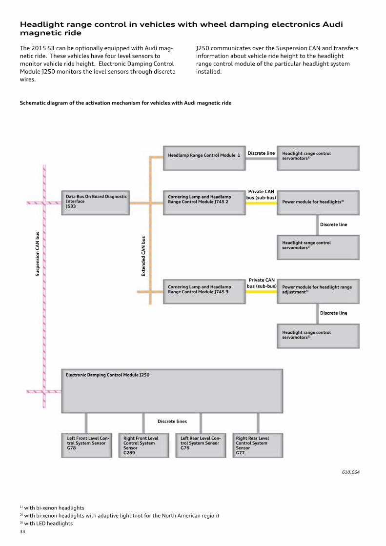
Headlight range control in vehicles with wheel damping electronics Audi magnetic ride
The 2015 S3 can be optionally equipped with Audi mag-netic ride. These vehicles have four level sensors to monitor vehicle ride height. Electronic Damping Control Module J250 monitors the level sensors through discrete wires.
J250 communicates over the Suspension CAN and transfers information about vehicle ride height to the headlight range control module of the particular headlight system installed.
Schematic diagram of the activation mechanism for vehicles with Audi magnetic ride
610_064
Su
spen
sion
CA
N b
us
Data Bus On Board Diagnostic InterfaceJ533
Headlamp Range Control Module 1
Exte
nd
ed C
AN
bu
s
Headlight range control servomotors1)
Cornering Lamp and Headlamp Range Control Module J745 2 Power module for headlights2)
Headlight range control servomotors2)
Cornering Lamp and Headlamp Range Control Module J745 3
Power module for headlight range adjustment3)
Headlight range control servomotors3)
Left Front Level Con-trol System Sensor G78
Electronic Damping Control Module J250
Right Rear Level Control System Sensor G77
Left Rear Level Con-trol System Sensor G76
Right Front Level Control System Sensor G289
1) with bi-xenon headlights2) with bi-xenon headlights with adaptive light (not for the North American region)3) with LED headlights
Discrete lines
Private CAN bus (sub-bus)
Discrete line
Discrete line
Private CAN bus (sub-bus)
Discrete line

34
LED tail lightPR no.: 8SK
LED tail lights are standard equipment on the Audi A3 for the North American region. They are activated by Vehicle Electrical System Control Module J519.
The tail lights are also activated if the vehicle is equipped with a Coming Home / Leaving Home function. The rear fog light and the reversing light are deactivated when the rear hatch is opened.
Light functions Illuminants used Activation mechanism Power
Brake light 9 LEDs 100 % approx. 3.5 watts
Tail light 2 LEDs with plastic optical fibres 100 % approx. 2 watts
Turn signal 20 LEDs 100 % approx. 3.5 watts
Back-up light Bulb H6W 100 % 6 watts
610_066
Turn signal
Brake light
Back-up light
Tail light
Tail lights
The bulbs of the rear hatch light can be accessed via a service flap. LEDs cannot be replaced. If faulty, the tail light in question must be replaced.

35
High-mounted brake light
The high-mounted brake light is attached to the rear window. It has a total of 48 LEDs. The component parts cannot be replaced. If defective, the entire module must be replaced.
The component parts of the high-level brake light cannot be replaced. If faulty, the complete component must be replaced. This is only possible after removing the rear spoiler.
License lights
The license plate lights for the 2015 A3 sedan feature LED technology. Both lights house two LEDs. As with the high-mounted rear brake light, they are activated by Vehicle Electrical System Control Module J519.
610_067a
610_068
High level brake lightM25

36
2
The 2015 Audi A3 Vehicle Electronics and Driver Assistance Systems
eSelf Study Program 970343
The 2015 Audi A3 Introduction
eSelf Study Program 990143
eSelf Study ProgramsFor further information about the technology of the The 2015 Audi A3, refer to the following eSelf Study Programs.
SSP 990143The 2015 Audi A3 Introduction
SSP 970343The 2015 Audi A3 Vehicle Electronics and Drivers Assistance Systems
SSP 960143The 2015 Audi A3 Running Gear and Suspension Systems
610_078a 610_079 610_080a

37
Notes

38
From the accessaudi.com Homepage:
• Click on the “ACADEMY” tab
• Click on the “Academy site” link
• Click on the Course Catalog Search and select “970243 - The 2015 Audi A3 Onboard Power Supply and Networking“
Please submit any questions or inquiries via the Academy CRC Online Support Form
which is located under the “Support” tab or the “Contact Us” tab of the Academy CRC.
Thank you for reading this eSelf-Study Program and taking the assessment.
The Knowledge Assessment is required for Certification.
You can find this Knowledge Assessment at:www.accessaudi.com
An On-Line Knowledge Assessment (exam) is Available for this eSelf-Study Program.
Knowledge Assessment

39
97
02
43
All rights reserved.Technical specifications are subject to change without notice.
Audi of America, LLC2200 Ferdinand Porsche DriveHerndon, VA 20171